user manual - kellogg idaho - turbo liner manuals/glascraft/manual... · user manual 5845 west 82nd...
TRANSCRIPT

MX Dispensing System
USER MANUAL
5845 WEST 82nd STREET INDIANAPOLIS, INDIANA 46278 U.S.A. Phone (317) 875-5592 Fax (317) 875-5456 E-Mail [email protected] Web www.glascraft.com

CONTENTS
Introduction
ABOUT THIS MANUAL 1 RELATED MANUALS 1 TECHNICAL VIDEO TAPES 1
Parts & Illustrations
MX SYSTEM LIST 2 OPTIONS 2 SERVICE KITS 2 21800-00 MX SYSTEM ASSEMBLY 3 21800-00 MX SYSTEM ASSEMBLY 4
21800-00 MX SYSTEM DETAILS 5 21800-00 ISOLATION BLOCK ASSEMBLY 6 21820-00 CONTROL BOX ASSEMBLY 7 21820-00 CONTROL BOX DETAILS 8 21820-00 CONTROL BOX DETAILS 9 21820-00 CONTROL BOX DETAILS 10 21820-00 MX SYSTEM SCHEMATIC 11 21825-XX MX PROPORTIONING UNIT ASSEMBLY 12 21825-XX MX PROPORTIONING DETAILS 13 21835-00 FLUID SECTION ASSEMBLY 14 21875-00 ISO HEAT EXCHANGER ASSEMBLY 15 21875-00 ISO HEAT EXCHANGER DETAILS 16 21875-00 ISO HEAT EXCHANGER SCHEMATIC 17 21885-00 POLY HEAT EXCHANGER ASSEMBLY 18 21885-00 POLY HEAT EXCHANGER DETAILS 19 21885-00 POLY HEAT EXCHANGER SCHEMATIC 20 21404-35 HOSE ASSEMBLY 21 17254-01 PROBLER SPRAY GUN 22
Safety
SAFE HANDLING AND USE OF SPRAY EQUIPMENT 23
Installation
ASSEMBLY INSTRUCTIONS 26 AIR SUPPLY CONNECTION 26 ELECTRICAL CONNECTION 26
Operation
PRE-OPERATION CHECK LIST 27 INITIAL START-UP PROCEDURE FILLING THE SYSTEM 27 OVER PRESSURE SYSTEM PROTECTION 28 OVER PRESSURE PROBLEM CORRECTION 29 CONTROL PANELS 29 PROPORTIONING PUMP 30 AIR MOTOR 30 SYSTEM SHUT- DOWN 31
Overhaul Procedure
BREAKING DOWN PUMP 32 DISASSEMBLE SUB-ASSEMBLIES 32 CLEANING 33 INSPECTION 33 RE-ASSEMBLE 33 FOR 19875-00 PUMPS 34
Limited Warranty Policy 35
Notes 36
If You Have an Equipment Problem 38
Added Supplement (AIR MOTOR) OPERATION INSTALLATION MAINTENANCE
1
INTRODUCTION
About This Manual Before operating, maintaining or servicing any Glas-Craft system, read and understand all of the technical and safety l iterature provided with Glas-Craft products. If you do not have the manuals and safety l iterature for your Glas-Craft system, contact your Glas-Craft distributor or Glas-Craft, Inc. In this Glas-Craft technical and safety publication, the following advisories will be provided where appropriate:
NOTE Is information about the procedure in progress.
CAUTION Is imperative information about equipment protection.
WARNING Is imperative information about personnel safety.
The information in this document is intended only to indicate the components and their normal working relationship typical use. Each assembly should be directed by a Glas-Craft distributor or made from the Glas-Craft assembly instructions provided. This manual provides information for the assembly, operation, maintenance and service of this Glas-Craft
product as used in a typical configuration. While it l ists standard specifications and procedures, some deviations may be found. In order to provide our users with the most up-to-date technology possible, we are constantly seeking to improve products. If technological change occurs after a product is on the market, we will implement that technology in future production and, if practical, make it available to current users as a retrofit, up-date or supplement. If you find some discrepancy between your unit and the available documentation, contact your Glas-Craft distributor to resolve the difference. Glas-Craft, Inc. reserves the right to change or modify this product as it deems necessary. Careful study and continued use of this manual will provide a better understanding of the equipment and process, resulting in more efficient operation, longer trouble-free service and faster, easier trouble-shooting.
Related Manuals For detailed component installation, operation and maintenance, refer to the following component manuals: COMPONENT MANUAL NUMBER 17254 Probler Gun GC-1023

2
PARTS & ILLUSTRATIONS
Includes
21800-00 MX FOAM SYSTEM * 6" AIR MOTOR, 1 PHASE, 200/240 VAC, 50/60 HZ., 60 AMP 17254-01 PROBLER GUN ASSEMBLY * W/ ROUND SPRAY MIXING CHAMBER 21404-35 HEATED HOSE ASSEMBLY, 35 FT. 21825-611 PROPORTIONING UNIT ASSEMBLY 21875-00 ISO HEAT EXCHANGER ASSEMBLY 21885-00 POLY HEAT EXCHANGER ASSEMBLY 59934-04 DIOCTYL PHTHALATE, 1 QT. 17661-03 GUN SERVICE KIT 21845-00 PUMP FLUID SECTION SERVICE KIT (TWO SUPPLIED) 18467-01 FLUID FILTER (TWO SUPPLIED) 17195-00 MIXING CHAMBER REMOVAL TOOL USER MANUALS
Options
21403-35 HIGH HEAT EXTENSION HOSE ASSY., 35 FT. > maximum Hose length, 210 FT.
Service Kits
17661-03 GUN SERVICE KIT

3
21800-00 MX SYSTEM ASSEMBLY
21825-611Ai r Mot or
Assy .
19882-00Cap
21802-00Sup port Mas t
21820-00Control Box
As s y .
18012-02Hose Cov er
21875-00H eat Ex changer
As s y .( ISO)
21883-01Materi al H ose
Assy .( ISO)
20068-00Cond uit
21874-00Thermocoupl e
Ass y .21884-01
Mat eri al HoseAssy.(P OLY)
21801-00MX Bas e
21885-00H eat E xchangerAs s y .( P OLY)
21323-00Condui t
17826-00N am e P l a t e
13424-01Cable Tie
19507- 04A i r Hos eA s s y .
21846- 00S uppo rt B rac ket
9945- 48CMa chin e S crew
7734- 07Lock Wash er
7733- 14Nu t
V iew DIso lat ion B lo c k De t a i l
V iew AProp ortio ning U nit A ss
Deta il
View B
Vie w CU p pe r Ma st D et a i l

4
21800-00 MX SYSTEM ASSEMBLY
218 39-00Wire Co nn ec t or
RS-1 41-02C ord Gri p
RS-1 41-01C ord Gri p
21 830- 00Ove r Pre ssure Sw it ch
21 809- 01M at erial H ose
A ssy .
21884 -01Mat erial H ose
Assy.( POLY )
218 83-01Ma te ria l Ho se
Assy.( I SO)
REAR VIEW REVISED 1 0/9
5
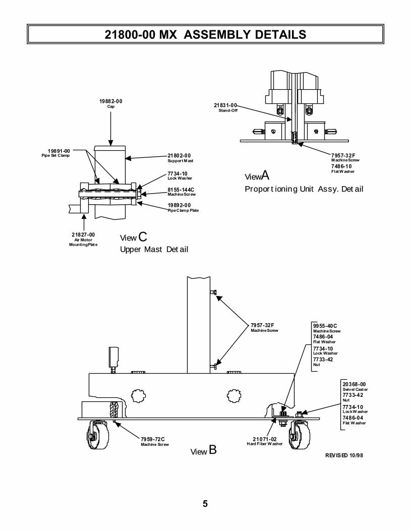
21800-00 MX ASSEMBLY DETAILS
7959-72CMachine Screw
21071-02Hard Fiber W asher
7957-32FMachine Screw
21831-00Stand-Off
7957-32FMachine Screw7486-10Flat W asher
19882-00Cap
19891-00Pipe Set Clamp
21827-00Air Motor
Mounting Plat e
21802-00Support Mast
7734-10Lock Washer
8155-144CMachine Screw
19892-00Pipe Clamp Plate
View CUpper Mast Detail
View B
View APropor tion in g Unit Assy. Detail
REVISED 10/98
9955-40CMachine Screw7486-04Flat Washer
7734-10Lock Washer7733-42Nut
20368-00Swivel Cast er7733-42Nut
7734-10Lock W asher7486-04Flat W asher

6
21800-00 ISOLATION BLOCK ASSEMBLY
21843-00Recept acle Guard
9115-28CMachine Screw
7959-72CMachine Screw
21316-01Elbow Fit ting
8560-08Fitt ing
21317-01Swivel Fi tting
7733-06Nut
7734-03Lock W asher
21813-00Front Plate
21815-00Recept acle
18371-00Fitting
21812-00Fluid Block 21316-01
Elbow Fitting
21317-01Swivel Fit ting
17597-03Tube Co nnector
20188-20CMachine Screw
21811-00Cover Plate
21819-00Label
20068-00Flexible Conduit
20067-00Conduit Connector
21814-00Rear Plate11021-41
Plug
20067-00Conduit Connector
REVISED 4/00
21874-00Th ermocoupleHo se As sy.

7
21820-00 CONTROL BOX ASSEMBLY
ISO POLY HOSE
OVER P RES SURE OVER P RES SURE
21852-00Label
21821-00Control Cabinet
21356-00Microprocessor
Control
17801-04Lense
21360-00Body
21361-00Lamp
21862-00Push Button
21856-00Inscript ion Cap
21887-01Cap
21866-00Coupling Plate
21886-00Body
21865-02Contact Block
21361-00Lamp
RS-118Label
21353-00Label
RS-119Label
RS-121Label
E
21854-00Button21856-00 Inscription Cap21887-03Cap21866-00Coupling Plat e21886-00Body
21865-01Cont act Block21361-00Lamp
REVISED 8/99

8
21820-00 CONTROL BOX DETAILS
M A I N
19941-00Strap W asher
CP-126U-Bolt
7486-07Nut
7734-07Lock W asher
RS-124Label
21362-04Circuit Breaker
21860-00Mounting Plate
7735-12CMachine Screw
7734-03Lock W asher
RS-141-01Cord Grip
20073-00U-Bolt
7486-08Flat W asher7734-12
Lock W asher
T4-161-03Cable Connector
5307-03Conduit Nut
22509-00Cable
7734-06Lock Washer
7733-12Nut21308-20C
Machine Screw
21821-00Control Box
4CR
7486-28Flat W asher
7733-06Nut
7734-03Lock Washer
21823-00Din Rail
21892-00Relay
21893-00Relay Socket
21894-00Clip
21823-00Rail
21822-00Elect ric Panel
21840-00Coil Relay7735-08CMachine Screw
7958-24CMachine Screw
7729-08Nut
7733-12Nut
21889-00Fuse Holder
21371-00Fuse
21164-00Fuse
21371-00Fuse
21888-00Circuit Breaker
7486-27Flat Washer
21824-16CMachine Screw
21821-00Control Box
VIEW A
B
B
SECTION B - B
D21861-00AluminumConductor
REVISED 8/99
9
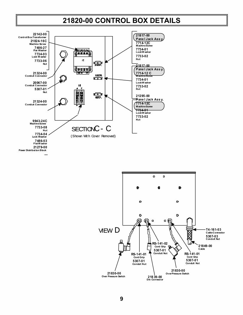
21820-00 CONTROL BOX DETAILS
T4-161-03Cable Connector5307-03Conduit Nut
21849-00Cable
21830-00Over Pressure Switch
RS-141-01Cord Grip5307-01Conduit Nut
218 39-00Din Connect or
21830-00Over Pressure Switch
RS-141-01Cord Grip5307-01Conduit Nut
RS-141-02Cord Grip5307-01Conduit Nut
VIEW D
22142-00Control Box Transformer
21824-16CMachine Screw
7486-27Flat Washer7734-03
Lock W asher
7733-06Nut
21324-00Conduit Connector
20067-00Conduit Connector
5307-01Nut
21324-00Conduit Connector
21817-00Pane l Jack Ass y.7714-12CMachine Screw7734-01Lock W asher
7733-02Nut
21817-00Pane l Jack Ass y.7714-12 CMachine Screw7734-01Lock W asher7733-02Nut
21295-00Pane l Jack Ass y.7714-12CMachine Screw7734-01Lock W asher7733-02Nut9943-24C
Machine Screw7733-08
Nut7734-04
Lock Washer
7486-03Flat W asher21279-00
Power Distribut ion Block
SECTION C - C(Shown With Cove r Removed)

10
21820-00 CONTROL BOX DETAILS
MAIN
17801-00Body17801-03Lense
17702-00Lamp
RS-124Label
T4-161-03Cable Connector
SECTION F-F
F
F
CC
VIEW E

11
21820-00 MX SYSTEM SCHEMATIC

12
21825-XX MX PROPORTIONING UNIT ASSEMBLY
1 6028 -0 1Hi t ch Pi n
7 957- 32 FMa ch in e S cre w
748 6 -1 0Fl at Wa she r
198 14-13Cl evis P in
216 13-48 CSet S crew
8 155-4 8CMac hi ne Sc rew
7 486-0 4F la t Wash er
7 957-4 0CMac hi ne Sc rew
7 486-1 0F la t Wash er
218 73- 00L ab el
8 155-4 0CMac hi ne Sc rew
7 486-0 4F la t Wash er
6 782-2 3T ee F i t t ing
8 560-0 3F it t in g
21 794 -00E xha ust S ile nc er
2182 6-00Air Mot o r
2182 7-00Mou nt i ng Pl at e
1998 4-00St a nd - Of f
2182 8-00Sh af t E xt en si on
2182 9-00Pu mp S ad dl e
1985 8-00St a nd - Of f
1059 9-40FSe t Sc rew
2161 4-64FSe t Sc rew
2187 2-00La be l
1985 9-00Pu mp M ou nt in g P
7966 -17Fit t i ng
2183 1-00St and- Off
REVISED 6 /98
See Detail B
See Detail A
P O L YO L I SO C YA N A T E

13
21825-XX MX PROPORTIONING DETAILS
7597-07Swivel Fit ting
4342-05Elbow Fit ting
8115-07Fitting
21838-00Lubricat or
8115-07Fitting
21837-00Regulat or
4342-05Elbow Fit ting
8115-07Fitt ing 21836-00
Poppet Valve
6782-04Tee Fitt ing
21666-013- Way Ball Valve
8115-07Fitting
See D etail C
Detail A Detail C
Detail B
21832-00Bushing
21833-00Retainer
21834-00Guide 8462-16
Fitting
6782-04Tee Fitt ing
REVISED 6/98

14
21835-00-00 FLUID SECTION ASSEMBLY
RATIO: 1:1
1005-02Snap Ring
21896-01Packing Ret ainer
9945-48CMachine Screw
7734-07Lock W asher
21440-00Solvent Cup Adapt er
13867-43O- Ring
21595-00Pump Seal
18295-01Support Washer
18227-00Pump Head
13867-43O- Ring
18289-00Pump Tie
Rod
21897-01Felt Wiper
21599-00Pump Shaft
18219-00Pump Cylinder
21597-00Transf er Housing
21803-00Spring
APS-133Ball
21595-00Pump Seal
FS-110Piston Guide
21598-00Transf erHousingSeat
19634-00Foot Valve Housing
19633-00Spring
APS-128Ball
13867-44O-Ring
APS-119Foot Valve Housing
P33-11Pump Base
7734-12Lock W asher
7733-17Nut
18289-00Pump Tie Rod
REPAIR KIT: 21845-00

15
21875-00 ISO HEAT EXCHANGER ASSEMBLY
77 3 4-0 4L oc k Washe r
2 1 056- 32 CMac hi ne S c rew
7 486-0 3Fl at Wa she r
2108 0-00Mo un t in g Brac ket
N OT E:O - Rin g A nd Pl ast ic Nu tS up pl ied Wit h 2 10 81 - 02
2108 1-02Con du it C on nect or
2107 1-01Fib er Washe r
1 1021 -24Plug
22 108-0 0Ove rt emp Sw it ch
210 68- 06CMa ch ine S c rew
2109 2- 00He at e r Ti e R od
2108 3-01Fit t ing
1102 1-24Pl ug
21 038-0 0Fib er Fit t ing
74 86-04Washer
77 3 4-1 0L oc k Washe r
7733 -42Nut
1102 1-23Pl ug
10 009-0 7E lbo w F it t i ng
2 1316 -01Elb ow Fi t t in g
21 308 -2 0CMa ch ine S c rew
773 4-0 6Lo ck Wa sh er
7 486-0 5Washer
2 1076 -00Fro nt En d P la t e
( IS O)
2 108 2- 00Mou nt i ng Bra cke t
210 65- 16CMac hi ne S c rew
21 072-0 0In su la t or P ad
2106 4-02O -Ri ng2 1091 -01
T urbu lat orSp ring
210 96-0 0Th ermo st at P ad221 08- 00
O ve rt emp S wit c h
210 68- 06CMa ch ine S c re w
8612 -08Ba nd Cl amp
74 86-05Washer
21 3 08- 20CM ac hin e S cre w
773 4 -0 6Lo ck Wa she r
2106 5- 16CM ac hin e S cre w
2107 2- 00In su la t o r Pa d
2107 9- 00Re ar E nd P lat e
( Un iversa l)
21 876- 00He at e r E le men t
2 1096 -00T he rmost a t Mo un t ingP ad
2 1057 -01F ib er Wa she r
21 059-0 0H eat er Tu be
Assy.
21 059-0 0H eat er Tu be
Assy.
21 881- 00G aug e
213 17-0 1S wivel F it t in g
2187 8-00Tee Fit t ing
7 966-1 7Fit t i ng
2187 9-00El bow Fi t t ing

16
21875-00 ISO HEAT EXCHANGER DETAILS
2187 6- 00He at e r E le men t
2 10 79-00Re ar En d P la t e( UN IVE RS AL )
861 2-08Ban d C lamp
2 1074 -0 0T he rmoc o u pl e
2 1096 -00T he rmost a t P a d
221 08- 00Overt e mp Sw it ch
2 1068 -0 6CM ac hin e S cre w
210 93-01Tub e Fi t t ing
210 91-03Tu rbu la t or Sp ri ng
2 1083 -01Fit t i ng
21 076-0 0Fro nt E nd P lat e
( ISO )
2 2108 -00O ve rt em p S wit c h
21 068- 06 CMa ch in e S cre w
2 106 9- 04CMa c hin e S cre w
2109 1-02Tu rbu la t or S pr in g
8 612- 08Ban d Clam p
2 1090 -0 0S en sor S le eve
2187 6-00Hea t er Ele men t
21 091-0 1T urb ulat o r Sp rin g
2109 6-00Th ermo st at M ou nt in g
P ad
21 059-0 0H eat er Tu be
Assy.
2 1064 -01O -Ri ng
2 1058 -00T ube Se nso r
Assy.20 363-0 1Nut
176 53-26Ba ck F erru le
1 7653 -01F ron t F erru le

17
21875-00 HEAT EXCHANGER SCHEMATIC
21097-00Overtemp Swit ch
2 3 OT 1
Left SideBot tom Tube
21061-02ISO Side
(ORANGE W IRE)
21079-00Rear End Plate(UNIVERSAL)
W ire Termination
Point
1 2 OT 2
2 1 OT 1
1 4 OT 2
Right SideBot tom Tube
Right SideTop Tube
Left SideTop Tube
ViewingDirect ion
FacingMachineCo nt rol
Box
21076-00Front End Plate
5754-05Terminal Lug

18
21885-00 POLY HEAT EXCHANGER ASSEMBLY
210 96-00Th ermo st a t Mou nt in g
P ad
21071 -01F ib er Wa sh er
21081-0 2Con du it Co nnect or
O- Rin g And Pla st ic N utSu pp lie d Wit h 21 08 1- 0 2
2 108 0-0 0Mou nt in g B rac ket
7486 -03F lat Washe r
773 4-0 4Lo ck Wash er
21 0 56- 32CMac hin e S c rew
21 30 8- 20CM ac hin e S c rew
773 4-0 6Lo ck Wash er
748 6-05Washer
21065 -1 6CMac hin e S cre w
21072 -0 0Insu lat o r Pa d
21079 -0 0Rea r En d P la t e( UNIV ERS A L)
8612-0 8Ba nd Cla mp
210 68- 06CMa chi ne S cre w
210 59-00H eat er Tube
Assy.
21097-0 0Ove rt emp Swi t ch
2 1096-00Th ermost a t P ad
2 1092- 00Hea t er T ie Rod
21 065- 16CMac hi ne S cre w
21 072-00Insul at o r Pa d
21 064-02O- Ring
21091-0 1Turbu lat or
Sp ring
210 83-01Fit t ing
11 021-24P lug21097- 00
Overt e mp Swit c h
210 68- 06CMac hi ne S cre w
110 21-24P lug
2 1038-00F iber F it t ing
748 6-04Washer
773 4-1 0Lo ck Washe r
773 3-42N ut
1 1021-23Plug
1000 9-07E lbow Fit t ing
2 1878-00Tee Fit t i ng
21316-01E lbo w F it t ing
21 3 08- 20CMac hin e S crew
773 4-0 6Lo ck Washe r
74 86-05Washer
21086 -00F ron t En d P lat e
( POLY )
21 082-00Mou nt i ng Brac ket
N OTE:
210 57-01Fib er Wa sher
21 059-00H eat er Tube
Assy.
796 6-17Fit t ing
21881 -00Gaug e
21 879-00E lbo w fi t t ing
2187 6- 00He at er Ele me
21317 -0 1Swi ve l F it t ing

19
21885-00 POLY HEAT EXCHANGER DETAILS
2 1074 -0 0T he rmoc o u ple
210 68- 06 CMac hi ne S c rew
2109 3-01T ub e Fit t ing
2 1091 -03Tu rbu lat or S pri ng
210 83-01Fit t ing
21 086-0 0Fro nt E nd P lat e
( P OL Y)
21 068- 06 CMa ch ine S c rew
2109 7-00Ove rt emp Sw it ch
861 2-08Ba nd C lamp
21 064-0 1O-Ring
21097- 00Overt e mp Swi t ch
210 96-00T he rmost at P a d
2106 9- 04CM ac hin e S cre w
2187 6- 00Hea t er Eleme nt
210 90- 00Se nsor Sle eve
2109 1-01Tu rbu la t or S pr in g
2 1091 -02T urb ula t or Sp ri ng
210 96-00T he rmost at Mou nt i ng
Pa d
861 2- 08Ba nd Clam p
2 1079 -00Rea r E nd Pl at e(UN IVE RSA L)
218 76- 00He at er E le me
210 58-00Tu be Sen sor
Assy.
210 59-00H eat er Tub e Assy .
176 53- 01Fro nt F erru le
176 53- 26Ba ck F errule
20 363-0 1Nut

20
21885-00 POLY HEAT EXCHANGER SCHEMATIC
21097-00Overt emp Switch
2 3 OT 1
1 2 OT 2
5754-05Terminal Lug
2 1 OT 1
1 4 OT 2
Left SideBot tom Tube
Left SideTop Tube
Right SideTop Tube
Right SideBott om Tube
21061-01Poly Side
(YELLOW W IRE)
21079-00Rear End Plate(UNIVERSAL)
W ireTermination
Point
ViewingDirect ion
Facing MachineCo nt rol
Box
21086-00Front End Plat e

21
21404-35 HOSE ASSEMBLY
21 588- 02C or d A ssy.
20 012- 00E lec t ric al Plu g
40 024- 00Bra id
FM- 494P rot e ct ive Jac ke t
18 012- 01Ho se I nsul at io n
20 011- 46He at T ap e
1950 7-03Air H os e Assy .
1810 1-00Fit t i ng
1949 0-01Swi vel Fit t i ng
1026 2-04Hose
1824 5-02Sh rink T ub in g
2141 1-00Alu min umT ap e
REVISED 8/9

22
17254-01 PROBLER SPRAY GUN
7730-08F 7716-08C
16809-00 16810-00 16808-00 16823-00 16811-01* T4-132** 16812-00 7 959-24C
16800-00
16807-00* T4-168** 17637-XX 9697-20C7554-12
17267-08C
PG-16
7716-08C 16867-00
PG-15 PG-12 T4-1448560-23
(Thread Size: #6 JIC)
9944-48C 1388-02 16805-00 7554-1216788-00
PG-17
9869- 19
PG-1816833-00
7554-53 PG-1916839-00
T4-171
16830-00(Thread Size: 1/4NPS)
16831-00
7554-09
7704-08C
19881-00
7554-07
7554-05 7554-29
16865-0016802-00
17259-16F16858-16F
7554-05 7554-03
16828-01
16804-00
16803-00
PG-15 PG-12 T4-143
PG-13(Thread Size: #6 SAE45)
REVISED 1/97
16832-00Assy.
16801-XXAssy.
17275-00Assy.
16821-00Assy.
16820-00Assy.
17275-00Assy.
16806- 00*16806- 01**
9944-28C17253-16C
* Used with 17254-00, -01, -02, -03 Gun Assembly ** Used with 17254-04, -05 Gun Assembly
REPAIR KIT: 19134-00
23
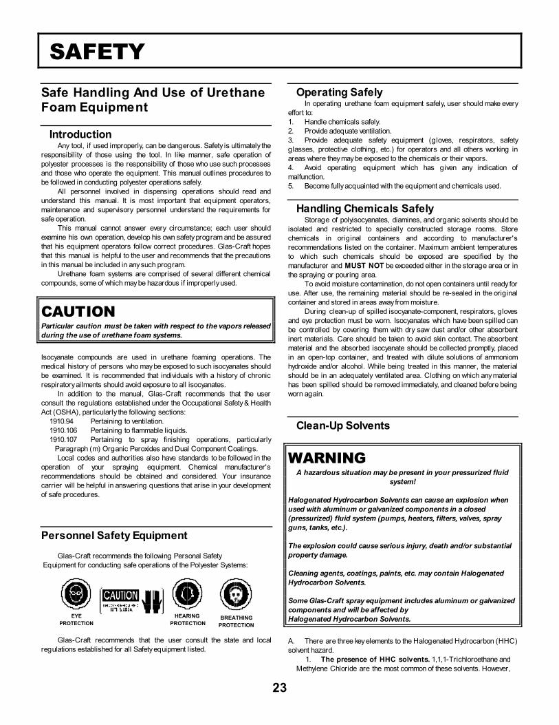
SAFETY Safe Handling And Use of Urethane Foam Equipment
Introduction
Any tool, if used improperly, can be dangerous. Safety is ultimately the responsibility of those using the tool. In like manner, safe operation of polyester processes is the responsibility of those who use such processes and those who operate the equipment. This manual outlines procedures to be followed in conducting polyester operations safely. All personnel involved in dispensing operations should read and understand this manual. It is most important that equipment operators, maintenance and supervisory personnel understand the requirements for safe operation. This manual cannot answer every circumstance; each user should examine his own operation, develop his own safety program and be assured that his equipment operators follow correct procedures. Glas-Craft hopes that this manual is helpful to the user and recommends that the precautions in this manual be included in any such program. Urethane foam systems are comprised of several different chemical compounds, some of which may be hazardous if improperly used.
CAUTION Particular caution must be taken with respect to the vapors released during the use of urethane foam systems.
Isocyanate compounds are used in urethane foaming operations. The medical history of persons who may be exposed to such isocyanates should be examined. It is recommended that individuals with a history of chronic respiratory ailments should avoid exposure to all isocyanates. In addition to the manual, Glas-Craft recommends that the user consult the regulations established under the Occupational Safety & Health Act (OSHA), particularly the following sections: 1910.94 Pertaining to ventilation. 1910.106 Pertaining to flammable liquids. 1910.107 Pertaining to spray finishing operations, particularly Paragraph (m) Organic Peroxides and Dual Component Coatings. Local codes and authorities also have standards to be followed in the operation of your spraying equipment. Chemical manufacturer's recommendations should be obtained and considered. Your insurance carrier will be helpful in answering questions that arise in your development of safe procedures.
Personnel Safety Equipment Glas-Craft recommends the following Personal Safety Equipment for conducting safe operations of the Polyester Systems:
EYE PROTECTION
HEARINGPROTECTION
BREATHINGPROTECTION
Glas-Craft recommends that the user consult the state and local regulations established for all Safety equipment listed.
Operating Safely In operating urethane foam equipment safely, user should make every effort to: 1. Handle chemicals safely. 2. Provide adequate ventilation. 3. Provide adequate safety equipment (gloves, respirators, safety glasses, protective clothing, etc.) for operators and all others working in areas where they may be exposed to the chemicals or their vapors. 4. Avoid operating equipment which has given any indication of malfunction. 5. Become fully acquainted with the equipment and chemicals used.
Handling Chemicals Safely Storage of polyisocyanates, diamines, and organic solvents should be isolated and restricted to specially constructed storage rooms. Store chemicals in original containers and according to manufacturer's recommendations listed on the container. Maximum ambient temperatures to which such chemicals should be exposed are specified by the manufacturer and MUST NOT be exceeded either in the storage area or in the spraying or pouring area. To avoid moisture contamination, do not open containers until ready for use. After use, the remaining material should be re-sealed in the original container and stored in areas away from moisture. During clean-up of spilled isocyanate-component, respirators, gloves and eye protection must be worn. Isocyanates which have been spilled can be controlled by covering them with dry saw dust and/or other absorbent inert materials. Care should be taken to avoid skin contact. The absorbent material and the absorbed isocyanate should be collected promptly, placed in an open-top container, and treated with dilute solutions of ammoniom hydroxide and/or alcohol. While being treated in this manner, the material should be in an adequately ventilated area. Clothing on which any material has been spilled should be removed immediately, and cleaned before being worn again.
Clean-Up Solvents
WARNING A hazardous situation may be present in your pressurized fluid
system! Halogenated Hydrocarbon Solvents can cause an explosion when used with aluminum or galvanized components in a closed (pressurized) fluid system (pumps, heaters, filters, valves, spray guns, tanks, etc.). The explosion could cause serious injury, death and/or substantial property damage. Cleaning agents, coatings, paints, etc. may contain Halogenated Hydrocarbon Solvents. Some Glas-Craft spray equipment includes aluminum or galvanized components and will be affected by Halogenated Hydrocarbon Solvents.
A. There are three key elements to the Halogenated Hydrocarbon (HHC) solvent hazard.
1. The presence of HHC solvents. 1,1,1-Trichloroethane and Methylene Chloride are the most common of these solvents. However,

24
other HHC solvents are suspect if used; either as part of paint or adhesives formulation, or for clean-up or flushing. 2. Aluminum or Galvanized Parts. Most handling equipment contains these elements. In contact with these metals, HHC solvents could generate a corrosive reaction of a catalytic nature. 3. Equipment capable of withstanding pressure. When HHC solvents contact aluminum or galvanized parts inside a closed container, such as a pump, spray gun, or fluid handling system, the chemical reaction can, over time, result in a build-up of heat and pressure, which can reach explosive proportions. When all three elements are present, the result can be an extremely violent explosion. The reaction can be sustained with very little aluminum or galvanized metal: any amount of aluminum is too much.
B. The reaction is unpredictable. Prior use of an HHC solvent without incident (corrosion or explosion) does NOT mean that such use is safe. These solvents can be dangerous alone (as a clean-up or flushing agent) or when used as a component of a coating material. There is no known inhibitor that is effective under all circumstances. Furthermore, the mixing of HHC solvents with other materials or solvents, such as MEK, alcohol, and toluene, may render the inhibitors ineffective. C. The use of reclaimed solvents is particularly hazardous. Reclaimers may not add any inhibitors, or may add incorrect amounts of inhibitors, or may add improper types of inhibitors. Also, the possible presence of water in reclaimed solvents could feed the reaction. D. Anodized or other oxide coatings cannot be relied upon to prevent the explosive reaction. Such coatings can be worn, cracked, scratched, or too thin to prevent contact. There is no known way to make oxide coatings or to employ aluminum alloys, which will safely prevent the chemical reaction under all circumstances. E. Several solvent suppliers have recently begun promoting HHC solvents for use in coating systems. The increasing use of HHC solvents is increasing the risk. Because of their exemption from many State Implementation Plans as Volatile Organic Compounds (VOC's), their low flammability hazard, and their not being classified as toxic or carcinogenic substances, HHC solvents are very desirable in many respects.
WARNING If you are now using Halogenated Hydrocarbon solvents in pressurized fluid systems having aluminum or galvanized wetted parts, IMMEDIATELY TAKE THE FOLLOW ING STEPS:
> Empty system, shut-off, completely depressurize in accordance with equipment service instructions.
> Remove equipment from service, disassemble in accordance with equipment servicing instructions.
> Inspect all parts for corrosion and/or wear. Replace any damaged parts.
> Thoroughly clean all parts of the equipment with a non-halogenated solvent and reassemble in accordance with equipment servicing instructions.
> Flush equipment with non-halogenated solvent. > Do NOT reuse equipment with HHC solvents or with materials
containing such solvents. > Material suppliers and/or container labels should be consulted
to ensure that the solvents used are compatible with your equipment.
NOTE
Glas-Craft is aware of NO stabilizers available to prevent Halogenated Hydrocarbon solvents from reaction under all conditions with aluminum components in a closed fluid system. TAKE IMMEDIATE ACTION... Halogenated Hydrocarbon solvents are dangerous when used with aluminum components in a closed fluid system.
F. Consult your material supplier to determine whether your solvent or coating contains Halogenated Hydrocarbon Solvents. G. Glas-Craft recommends that you contact your solvent supplier regarding the best non-flammable clean-up solvent with the heat toxicity for your application. H. If, however, you find it necessary to use flammable solvents, they must be kept in approved, electrically grounded containers. I. Bulk solvent should be stored in a well-ventilated, separate building, 50 feet away from your main plant. J. You should allow only enough solvent for one day's use in your laminating area. K. "NO SMOKING" signs must be posted and observed in all areas of storage or where solvents and other flammable materials are used. L. Adequate ventilation (as covered in OSHA Section 1910.94 and NFPA No. 91) is important wherever solvents are stored or used, to minimize, confine and exhaust the solvent vapors. M. Solvents should be handled in accordance with OSHA Section 1910.106 and 1910.107.
Toxicity of Chemicals A. Glas-Craft recommends that you consult OSHA Sections 1910.94, 1910.106, 1910.107 and NFPA No. 33, Chapter 14, and NFPA No. 91. B. Contact your chemical supplier(s) and determine the toxicity of the various chemicals used, as well as the best methods to prevent injury, irritation and danger to personnel. C. Also determine the best methods of first aid treatment for each chemical used in your plant.
First Aid If chemicals containing isocyanates are splashed on the skin, they can produce ill effects. Steps to counteract such effects should be started immediately. 1. Apply Tincture of Green Soap, full strength, to the contaminated area. If Tincture of Green Soap is not immediately available, wash the exposed area repeatedly with soap and water. Soap and water is not as desirable as using Tincture of Green Soap because many isocyanate components are not easily dissolved in water. In addition, soap and water does not form a barrier to the isocyanates. 2. After approximately two to four minutes, wash off the Tincture of Green Soap with water. If there is still an indication of isocyanate present, repeat the application. If the isocyanate contamination is on the facial area, care must be taken to avoid getting the Tincture of Green Soap in the eyes. 3. If the person develops breathing difficulties, oxygen should be administered. Quite often the exposed person will experience residual effects such as coughing spells. CONTACT PHYSICIAN IMMEDIATELY.
WARNING Contact a doctor immediately in the event of an injury and give him the information you have collected. If your information includes first aid instructions, administer first aid immediately while you are contacting the doctor.
4. If a person accidentally swallows isocyanates, large amounts of water should be swallowed immediately. Vomiting should then be induced by patient sticking his finger down his throat, or by swallowing large quantities

25
of warm salt water or warm soapy water. After vomiting, more water should be taken to dilute isocyanate further. CONTACT PHYSICIAN IMMEDIATELY.
Ventilation
WARNING Hazardous concentrations of some chemical vapors exist before they can be smelled. Chemical component suppliers should be contacted to determine at what concentrations the vapors of the chemicals they supply become dangerous, and the procedures and equipment needed to detect such dangerous concentrations. Such equipment should be obtained. Adequate ventilation must be provided in any area where foam chemicals are sprayed or poured, and wherever the material containers are opened.
In industrial applications, foaming operations should be restricted to specific areas, and proper ventilation should be provided in these areas to prevent chemical vapors from spreading. Spray foaming operations MUST be restricted to a spray booth where a minimum exhaust of 100 feet per minute at the face of the booth is provided. Special care should be taken to prevent unsuspecting personnel both inside and outside of the plant from being exposed to chemical vapors. The chemical vapors should be exhausted to atmosphere in such a manner and at a sufficiently low concentration that personnel outside the plant are not exposed to dangerous concentrations of chemical vapors. Refer to OSHA Standards, sub-part G, 1910.107 and particularly sub-section (m) for Federal standards. State and local authorities may have applicable statutes or regulations concerning ventilation. n contractor applications (for example, at a construction site, inside building or other enclosed space), the forced ventilation normally provided is likely to be inadequate. These applications, therefore, usually REQUIRE the use of forced, fresh air respirators for all persons in the areas where foaming operations are conducted or where the chemical vapors are likely to spread. In industrial and contractor applications, it is advisable to run frequent tests to determine the exact concentration of isocyanate vapor in the air. Industrial equipment is available for making such determinations. Your chemical supplier can recommend such equipment and procedures.
Proper Safety Equipment All persons spraying or working is areas where forced air ventilation is not adequate to remove isocyanate vapors from the air MUST use an approved (U.S. Bureau of Mines) fresh air supplied respirator. Respirators should be regularly inspected, cleaned and disinfected according to good practices. Records must be kept of the inspections. The user MUST have a medical clearance indicating that he can safely use a respirator. Respirators must fit securely; beards prevent a tight seal around the face. Eye glasses have to be given special attention and contact lenses are prohibited. Safety goggles, gloves and other protective devices are suggested for operators of foaming equipment. Refer to OSHA Standards, sub-part 1, 1910.132, 1910.133 and 1910.134 for Federal standards. IF YOU HAVE ANY QUESTIONS REGARDING THE ABOVE PRECAUTIONS OR ANY SERVICE OR OPERATION PROCEDURES, CALL YOUR GLAS-CRAFT DISTRIBUTOR OR GLAS-CRAFT, INC.
Notice All statements, information and data given herein are believed to be accurate and reliable but are presented without guaranty, warranty or responsibility of any kind expressed or implied. The user should not assume that all safety measures are indicated or that other measures are not required.
5845 WEST 82nd STREET, SUITE 102 INDIANAPOLIS, INDIANA 46278 U.S.A.
PHONE (317) 875-5592 FAX (317) 875-
5456
APRIL 1996

26
INSTALLATION
Assembly Instructions
NOTE The Glas-Craft MX System is factory assembled. If any questions arise concerning air or electrical connections, please refer to i l lustrations located in the forward portion of this User Manual or contact your Glas-Craft distributor.
A. Air Supply Connection An air source which delivers a constant 45 CFM @ 100 PSI should connected directly to the Fitting, P/N 8560-03, mounted on the Proportioning Unit Air Motor Regulator, P/N 22516-00. (see “22520-00 PROPORTIONING ASSEMBLY, Detail A” i l lustration) The air l ine to the Console should be a minimum 1/2 inch inside diameter (I.D.) if it is 25 feet or less in length. Should it be over 25 feet in length, the air l ine should be a minimum 3/4 inch I.D.
B. Electrical Conections 1. Prior to connecting Main Power, insert Hose Electrical Plug, P/N 20012-00 into the Receptacle, P/N 21815-00 located on the front of the Hose Block. (see “HOSE BLOCK ASSEMBLY” il lustration)
WARNING Disconnect or turn off Main Power source before opening Control Panels Boxes to make any repairs or before making any electrical repair of any type to the MX system.
CAUTION If you do not understand the electrical hook-up described above, consult your local Glas-Craft distributor OR a qualified electrician.

27
OPERATION Pre-Operation Checklist A. Check that all fittings are securely tight. B. Check electrical hook-up (qualified electrician recommended). C. Circuit Breaker on Control Box should be switched to OFF position. D. Main Air Regulator turned (counter clock-wise) to OFF position.
WARNING Do not place any part of the body in the path of the material spray. Do not point the gun at or near other personnel. Do not look into the Mixing Chamber orifice at any time. Because of the hazardous materials used in this equipment, it is recommended that the operator use an air mask, goggles, protective clothing, and other safety equipment as prescribed by current regulations, recommendations of the chemical suppliers, and the laws in the area where the equipment is being used.
A. Initial Start-Up Procedure
With all material and air l ines connected and power cable attached, the system is now ready for start-up. Filling The System 1. With all material and air l ines connected and power cable attached to the system, the system is now ready to be fi l led with material. With transfer pumps in place, adjust regulators on transfer pumps to 30-50 psi to fi l l the system. Transfer pumps will cycle to fi l l pumps, heaters and hoses and then stop. 2. Remove the Side Blocks, P/Ns T4-143 and T4-144, on the front housing of the Gun, by removing Screws, P/N 9944-48C.
3. Place separate clean containers under each individual Side Block. Open manual Material Valves (black arrow forward, see Fig. 2 & 3) on each Side Block to allow trapped air to escape the Hose and material to flow into the containers until all air is purged from the material system. (see Fig. 1)
Fig. 1
NOTE Remember to dispense one to two gallons of material to clear the system of grease and plasticizer that was used during factory testing.
4. Close manual Material Valves. Material pressures gauges should now register approximately equal pressure. If one side registers considerably more pressure than the other side, go to the high pressure side and bleed off some pressure by slightly opening the manual Material Valve on the Side Block over the container. Bleed pressure until both sides are approximately the same pressure. 5. Dispose of waste material properly and in accordance with chemical suppliers instructions and local, state and federal regulations.
NOTE Before re-assembling Side Blocks, lubrication can be applied by dabbing a white l ithium grease into holes inside of Gun Front Housing and wiping grease over Side Block Seals. Grease will purge itself when air valve is turned on at Gun and Gun is triggered.

28
6. Clean and lubricate Side Blocks and Seals thoroughly and re-assemble on Gun. Make certain that Side Block Screws are tighten securely. 7. Refer to Glas-Craft Material Operating Instructions for proper preparation of material, i.e, mixers, etc. 8. Make sure Main Proportioning Unit regulator, P/N 22516-00, is dialed (counter clock-wise) to zero. 9. Slowly adjust Regulator, P/N 18199-02, on the MX system to control Transfer Pumps. Regulator should be dialed up to 90-100 psi.
NOTE Turn Transfer Pump Air Regulator on slowly. Pumps should cycle slowly until hoses are full of material.
10. Turn on Main Power. 11. Turn on Hose Control. This is done by pushing in the green button. Adjust temperature to desired setting by depressing the blue “SET” button and press either or button on the Controller simultaneously until desired temperature setting is achieved.
NOTE Allow proper time for hose to warm up (approximately 15-20 minutes).
NOTE To adjust temperature on Hose Controller, push and hold in blue button. Then push the up or down arrow to increase or decrease temperature. To see actual temperature of l iquid in hose, push blue button once and release. The actual temperature will then be displayed for 10 seconds.
12. Turn on the ISO and POLY Heaters by pushing in the green buttons. 13. Adjust temperature to desired setting. ISO and POLY Controllers function exactly the same as the Hose Controller.
NOTE Allow proper time for material to be heated (approximately 3-5 minutes).
14. Turn Purge Air and Material Valves ON at Gun. (see Fig. 2 & 3)
Fig. 2 Fig. 3
15. Relieve any excess pressure by triggering the gun. 16. Dial-up Main Proportioning Unit regulator, P/N 21825-611, to desired pressure.
NOTE Standard operating pressure should be set at 100 psi.
17. The system is now ready for operation.
B. Over Pressure System Protection
The MX system incorporates monitors for high pressure monitoring. These monitoring devices will

29
prevent the MX system from continued operation if high pressure situations develop. There are two pressure sensors located on each proportioning pump. The high pressure sensor is located at the outbound of the fluid section. The high pressure monitoring sensor will engage if fluid pressure increases above 3200 psi. If a high pressure situation develops, the sensor will detect this and immediately engage the hold-in circuit. This will disengage power to the air motor and it wil l stop cycling. It wil l also turn the heater off. On the control box panel, there are two yellow lighted push buttons marked over pressure. One of these push buttons will be il luminated after the monitoring sensor engages, indicating where the problem is located (ISO or Poly). In the over pressure situation, the system will remain shutdown until it is manually reset. At this point, it is necessary to determine if the problem is an over pressure situation. When the sensor engages, the system will be frozen, giving you the pressure readings at the time the problem was detected. Inspect the fluid pressure gauges, in an over pressure situation, one of the fluid pressure gauges will be significantly higher than the other gauge.
WARNING When main power to unit is on, the console will have wires that are live. Disconnect or turn off main power source before opening console to make any repairs.
WARNING Before performing any repairs on the system, ALL AIR and FLUID PRESSURES SHOULD BE RELIEVED TO ZERO (BLEED-OFF)!
C. Over Pressure Problem Correction
1. Determine if the problem is high pressure related. 2. Relieve system hydraulic pressure. 3. Turn off main power 4. Fix the problem area:
a. Potential high pressure causes: - Restriction - Overheating material in static position - ISO fi lter at gun
5. Re-start system for operation 6. Once the power has been turned off and problem solved, and the main power is turned on again, the over/under pressure lighted buttons will automatically be reset.
D. Control Panels MX System Control Panel Specifications
• 208 VAC • 60 Amp • Singe Phase • 50/60 Cycles
Main power cord has three wires:
• Black - L1 (Power) • White - L2 (Power) • Green - Ground
CAUTION If you do not understand the electrical hook-up described above, consult your local Glas-Craft distributor OR a qualified electrician. It is recommended that a qualified, l icensed electrician should install power to the supply disconnect. You should always follow all local or national electrical codes.

30
CAUTION Disconnect power source BEFORE attempting any repairs or opening the Control Boxes. Access to internal parts is limited to qualified personnel ONLY! Place Main Power Breaker in OFF position BEFORE disconnecting power cables. This equipment is not approved for use in hazardous locations as set forth in the National Electrical Code Article 500 and Sub-Part “S” of the OSHA Standards. The green, small bulb l ights on the Control Panel are cycle l ights. They will i l luminate when that component is actively cycling.
E. Proportioning Pump Air Motor
• 6 inch diameter air motor with a 4 inch stroke.
NOTE Supply air to air motor should be clean, dry air. A Gauge/Regulator/Water Trap is located on the in-bound Main Air port of the Air Motor. The Water Trap should be drained after each use. Fluid Sections The wiper/lubrication cup at the top of each fluid section is designed to keep piston shaft clean and lubricate throat seal. This special design requires very l ittle maintenance. Each month:
1. Wipe any residue from the mouth of the lubrication cup.
2. Add 1 teaspoon of a suitable lubricating solution.
Hoses Each MX system is supplied with a 35 ft. high Heated Hose assembly.
A temperature sensing thermocouple is run 13 ft. into the B-side of the Hose assembly. This is where actual (process) material temperature is measured and reflected at the Hose Controller. If additional hose lengths are required:
• 21404-35 Lead Hose • 21403-35 Extension Hose
The P/N 21404-35 Lead Hose is supplied with the MX system. If additional hose assemblies are required, order P/N 21403-35 Extension Hose. The P/N 21404-35 Lead Hose must be attached to the Gun. Extension Hoses (P/N 21403-35) are added to the Lead Hose and then attached to the machine.
NOTE The MX system, with 35’ hose assembly, has a 1 amp hose fuse in the lower control box. If extra length hoses are required, the hose fuses must also be changed as follows… Hose Length Current Rating 35’ 1.55 amp 70’ 3.10 amp 105’ 4.64 amp 140’ 6.19 amp 175’ 7.74 amp 210’ 9.29 amp Stroke Counter OPTIONAL: contact Glas-Craft Technical Service Department. • Per stroke the total v olume output will be:
.021 x strokes = U.S. gallons. (with 1:1 pumps)
F. System Shut-Down 1. Turn Main Circuit Breaker to OFF position. 2. Perform Gun maintenance as follows:
a. Check for leaking Seals, P/N 16811-00: Turn OFF Gun incoming air by closing Gun Air Switch.
Wait approximately 10-20 seconds, then turn ON incoming air by opening Gun Air Switch.
Repeat two or three times.

31
If any material has been purged from the Gun, the Seals, P/N 16811-00 are leaking.
Correct leaks by replacing seals and re-checking.
b. Check for leaking Material Valve, P/N PG-15:
Turn OFF both Material Valves. Trigger Gun several times. Turn OFF Gun incoming air by closing Gun Air Switch.
Trigger Gun several times. If additional material is purged, the Material Valves are leaking.
Correct leaks by taking off Black Knobs and turning packing 1/8 to 1/4 turns at a time until leak has stopped. Re-check.
c. Check Side Blocks: Turn OFF the Air Switch on Gun.
WARNING Before removing Side Blocks make certain that both Gun Material Valves are in the fully OFF positions! Refer to Figures 4 and 5. If Material Valves are on when Side Blocks are removed, the Gun will quickly become encased in urethane!
WARNING Point Gun Side Blocks down, away from all personnel. Existing fluid pressures could cause material to exit the Side Blocks with considerable force.
Take off Side Blocks by removing Screws, P/N 9944-48C.
Examine the sides of the Mixing Chamber, P/N 17637-XX for scratches and/or material
build-up. Carefully, without scratching the seal surfaces (sides), remove any accumulated material. Solvent can be used to wash accumulated material off of Chamber, Side Blocks, etc. Keep Gun Chamber ti lted toward the ground so that solvent does not run back into Gun. Certain solvents will attack O-Rings on Chamber Shaft causing swelling and deterioration of O-Rings.
Place generous amounts of high quality, white l ithium grease in each side of the Gun Front Housing and on the Side Block Seals.
Use a No. 50 Dril l Bit to clean out the Mixing Chamber exit passage. Use a No. 55 Dril l Bit to clean the inlet side holes of the Mixing Chamber taking care not to scratch the Mixing Chamber's polished surfaces.
Re-assemble the Side Blocks and tighten Screws securely. Grease should appear at the tip of the Mixing Chamber. DO NOT open Air Switch on Gun because this will purge grease from the Gun. The grease should be allowed to remain in the Gun overnight.
3. Reduce Main Air Regulator setting to ZERO. 4. Visually inspect entire system for leaks. 5. Turn OFF Main Air Supply.
CAUTION Do not bleed fluid pressure from the system.

32
OVERHAUL PROCEDURE
19875-00 (-01) Pumps 21835-00 Pumps
1. Dump pressure off system
WARNING Be sure air and power are off to system.
This is achieved by splitting side blocks of of gun, opening ball valves and purging materials into clean containers.
2. Flush system side to be rebuilt with suitable solvent.
NOTE This is optional, it makes the process easier.
3. Disconnect inlet fitting from the bottom of the pump. 4. Disconnect outlet fitting from the top of the pump.
a. Systems with Over Pressure Valve: remove DIN connector from switch, Phill ips screw.
b. Remove Over Pressure Switch from fitting.
CAUTION Do not immerse Over Pressure Valve in solvents externally. (Flushing will not affect).
5. Remove pump from base.
1. Loosen and remove P/N 7729-10
Nylon Lock Nut from yoke. (Older MX Systems), loosen allen screw screw in yoke, remove Hitch Pin, pull out Clevis Pin.
b. Loosen and remove four bolts, P/N 9945-48C.
Breaking Down Pump 1. Loosen four nuts, P/N 7733-17 at the base of
pump and remove, break loose, in a criss-cross pattern.
2. Remove Base, P/N P33-11 from Tie Rods, P/N
18289-00.
NOTE On P/N 21835-00 pumps, watch out for APS-119, APS-128, & 19633-00. The 19633-00 will push these parts out. Observe which side of the APS-119 comes out, Keep right side up for diagnostics. 3. Remove Valve Housing from the cylinder. P/N UF-118 on 19875-00 pump.
P/N, 19634-00 on 21835-00 pump. 4. Using a rubber mallet, tap shaft out through the
bottom of the cylinder, P/N 18219-00. 5. Remove cylinder, P/N 18219-00 from Pump
Head, P/N 18227-00. 6. Remove Cup Adapter, P/N 21440-00 from Pump
Head, P/N 18227-00.
Disassemble Sub-Assemblies 1. Cup Adapter, P/N 21440-00.
a. Remove Support Washer, P/N 18295-01.
b. Remove Seal, P/N 21595-00.
c. Remove Snap Ring, P/N 1005-02, Nylon Washer, P/N 21896-01, & Felt Wipers, P/N 21897-01.
2. Shaft Assembly:
a) Remove P/N 21598-00, Transfer Seat from P/N 21597-00, Transfer Housing. Watch for P/N APS-133, Ball and P/N 21803-00, Spring. The Ball is loaded with spring tension.

33
b. Remove FS-110, Piston Guide and P/N 21595-00 Pump Seal.
Cleaning 1. Thoroughly wash all parts in suitable solvent. 2. If parts have any build-up of hardened material, it
is acceptable to polish parts with fine sand paper,(1200 grit) or steel wool(000).
3. It is recommended that the cylinder be honed
with a fine grit bead honer,(P/N RK5-2).
Inspection 1. The Pump Cylinder, P/N 18219-00 inner wall
should be smooth. No pitting or scarring should be seen. If slight scars show in the wall, they must not be able to be felt with a finger nail.
2. The Pump Shaft, P/N 21599-00 must not have
any scoring, pitting, or build up of any debris on the shaft.
3. Set the Ball, P/N APS-133 in the Seat, P/N
21598-00 and hold up to a l ight. Observe for l ight between seat surface and the ball.
NOTE If a large sliver of l ight shows, check for debris or scarring on Seat or Ball.
4. P/N APS-128 & P/N APS-119 repeat the above step.
NOTE The APS-119 is reversible, you can use either side.
Re- Assemble
NOTE All parts underlined are contained in repair kit.
2. Soak P/N 21897-01 in a l ight weight, non detergent oil, then install in P/N 21440-00.
3. Install P/N 21896-01, push down and install Snap
Ring P/N 1005-02 in groove.
4. On bottom side of P/N 21440-00 install P/N 21595-00 in housings so that the lip faces out.
5. Lubricate and install O-Ring, P/N 13867-43 on
bottom groove.
6. Install P/N 18295-01 with l ip facing toward P/N 21595-00 seal.
7. Place P/N 21595-00 Seal and P/N FS-110 guide
on P/N 21597-00. The lips of the Seal will face away from P/N FS-110.
8. Set P/N 21803-00 Spring in P/N 21597-00
Housing and set APS-133 Ball on Spring. 9. Apply blue lock-tite to the threads of P/N 21598-
00 and install on P/N 21597-00. Tighten these two parts!
10. Lubricate and install two P/N 13867-49 O- Rings
on P/N 18219-00 cylinder. 11. Using a light weight non-detergent oil, coat the
seal on the shaft assembly and the walls of the cylinder, then install the shaft assembly into the cylinder, leave approximately 4” of the shaft exposed on the top side.
12. Install cylinder/shaft assembly into P/N 18227-00
Pump Head, careful not to cut O-Ring for Pump P/N 21835-00.
13. With the Pump Assembly upside down, (easy if
clamped in a vise) install Foot Valve Housing P/N 19634-00.
14. Set P/N 19633-00 Spring in place and set P/N
APS-128 Ball on Spring.
15. Lubricate and install P/N 13867-44 O-Ring in groove of P/N 19634-00.
16. Lubricate the outer edge of P/N APS-119 and set
top of ball, square and center flats of P/N APS-119 and P/N 19634-00.

34
17. Gently set P/N P33-11 through P/N 18289-00 Tie Rods and push down square and firm until it sets down over cylinder O-Ring.
18. Continue holding P33-11 down, install (4) P/N
7734-12 Lock Washers and hand thread (4) P/N 7733-17 Nuts.
19. Tighten P/N 7733-17 in a criss- cross pattern until
tight.
For 19875-00 Pumps: 1. Set UF-118 in cylinder.
2. Set P/N APS-128 in body.
3. Lubricate P/N 13867-44 and install in groove of
UF-118.
4. Install P/N APS-119.
5. Gently set P/N P33-11 through P/N 18289-00 Tie Rods and push down square and firm until it sets down over cylinder O-Ring.
6. Continue holding P33-11 down, install 4 P/N
7734-12 Lock Washers and hand thread 4 P/N 7733-17 Nuts.
7. Tighten P/N 7733-17 in a criss- cross pattern until
tight.
8. Lubricate P/N 21595-00 Seal (inside of P/N 21440-00 housing.
9. Gently push down over Pump Shaft P/N 21599-00
and set flush to P/N 18227-00 Pump Head. 10. Re-install pump in reverse order of removal.

35
LIMITED WARRANTY POLICY
GLAS-CRAFT, INC. (“Glas-Craf t”) warrants to the original Purchaser of Glas-Craf t manuf actured equipment and parts, that all Glas-Craf t manuf actured equipment and parts will conf orm to their published written specif ications and be f ree of def ects in workmanship and material f or a period of one (1) y ear f rom the original date of installation. Glas-Craf t makes no warranty to any one other than the original Purchaser. If any Glas-Craf t manuf actured part or equipment is f ound to be def ectiv e in workmanship or material within the one-y ear period f rom the date of installation, as determined solely by Glas-Craf t, Glas-Craf t, in its sole discretion, will either repair or replace the def ectiv e part or equipment at Glas-Craf t’s cost, including f reight charges both way s, or credit or ref und the purchase price f or the def ectiv e equipment or part. A warranty claim will be honored only when: 1. Glas-Craf t has been inf ormed, in writing, of any such def ect in workmanship or material within ten (10) day s af ter
discov ery by the original Purchaser; 2. An of f icial of Glas-Craf t has issued a return authorization number; and 3. The claimed def ectiv e equipment or part has been returned to Glas-Craf t by the original Purchaser, f reight prepaid (with
proper return authorization number(s) attached), to: Glas-Craf t, Inc., 5845 West 82nd Street, Suite 102, Indianapolis, IN 46278, U.S.A.
This warranty shall not apply to any equipment or parts that hav e been altered or repaired by any one other than Glas-Craf t or to def ects or damage resulting f rom improper installation, misuse, negligence, accident, or use not specif ied by Glas-Craf t. This warranty shall not apply to any equipment where any parts or components were replaced by any parts or components not manuf actured or supplied by Glas-Craf t. The decision by Glas-Craf t shall be conclusiv e and binding on Purchaser. Glas-Craf t does not warrant that any equipment or parts sold to Purchaser meet or comply with any local, state, f ederal, or other jurisdiction’s regulations or codes. Glas-Craf t does not warrant that any equipment or part sold to Purchaser, when used indiv idually or in concert with any other part, equipment, dev ice, component or process, does not inf ringe on any patent rights of any third party . Glas-Craf t only warrants that it has no specif ic knowledge of any such inf ringement. Glas-Craf t makes no warranty as to any parts or equipment manuf actured by others. Purchaser shall look solely and only to the manuf acturer of such parts or equipment with respect to any warranty claims. Glas-Craf t hereby assigns to Purchaser the original manuf acturer’s warranties to all such equipment and parts, to the f ull extent permitted. THE AFORESAID WARRANTY IS IN LIEU OF ALL OTHER WARRANTIES, EXPRESS OR IMPLIED. SPECIFICALLY THERE ARE NO WARRANTIES OF MERCHANTABILITY OR FITNESS FOR A PARTICULAR PURPOSE, WHICH WARRANTIES ARE SPECIFICALLY DISCLAIMED. Glas-Craf t shall not be liable f or any loss or expense resulting f rom damage or accidents caused by improper use or application of materials manuf actured or sold by Glas-Craf t or its distributors or agents. UNDER NO CIRCUMSTANCES SHALL GLAS-CRAFT’S LIABILITY EXCEED THE AMOUNT PURCHASER PAID FOR THE CLAIMED DEFECTIVE EQUIPMENT OR PART. UNDER NO CIRCUMSTANCES SHALL GLAS-CRAFT BE LIABLE FOR INCIDENTAL OR CONSEQUENTIAL DAMAGES OR FOR LOST PROFITS. No action arising f rom or relating to any goods manuf actured by or purchased f rom Glas-Craf t may be brought more than one (1) y ear af ter the cause of action accrues.

36
NOTES ____________________________________________________________________________________
____________________________________________________________________________________
____________________________________________________________________________________
____________________________________________________________________________________
____________________________________________________________________________________
____________________________________________________________________________________
____________________________________________________________________________________
____________________________________________________________________________________
____________________________________________________________________________________
____________________________________________________________________________________
____________________________________________________________________________________
____________________________________________________________________________________
____________________________________________________________________________________
____________________________________________________________________________________
____________________________________________________________________________________
____________________________________________________________________________________
____________________________________________________________________________________
____________________________________________________________________________________
____________________________________________________________________________________
____________________________________________________________________________________
____________________________________________________________________________________
____________________________________________________________________________________
____________________________________________________________________________________
____________________________________________________________________________________
____________________________________________________________________________________

37
NOTES ____________________________________________________________________________________
____________________________________________________________________________________
____________________________________________________________________________________
____________________________________________________________________________________
____________________________________________________________________________________
____________________________________________________________________________________
____________________________________________________________________________________
____________________________________________________________________________________
____________________________________________________________________________________
____________________________________________________________________________________
____________________________________________________________________________________
____________________________________________________________________________________
____________________________________________________________________________________
____________________________________________________________________________________
____________________________________________________________________________________
____________________________________________________________________________________
____________________________________________________________________________________
____________________________________________________________________________________
____________________________________________________________________________________
____________________________________________________________________________________
____________________________________________________________________________________
____________________________________________________________________________________
____________________________________________________________________________________
____________________________________________________________________________________
____________________________________________________________________________________

38
IF YOU HAVE AN EQUIPMENT PROBLEM…
If you have a problem that requires Distributor or Glas-Craft Service Department help, gather the following information BEFORE you pick-up the telephone.
Model No. Serial No. SPRAY GUN SYSTEM TYPE of MATERIAL BEING SPRAYED SYSTEM GUAGE PRESSURES ISO HEATER GUAGE PSI POLY HEATER GUAGE PSI MATERIAL PUMP AIR MOTOR PSI MAIN AIR LINE PRESSURE at SYSTEM PSI MAIN AIR LINE VOLUME CFM COMPRESSOR SIZE HP COMPRESSOR to SYSTEM SUPPLY LINE SIZE
INCHES
Have a general equipment or operation question? You can contact the Glas-Craft Service Department via E-Mail at
S P R A Y G U N MO D EL N O . _ _ _ _ _ _ _ _ MA TER IA L P U MP MO D EL N O . _ _ _ _ _ _ _ _ _ C A TA LYS T S YS TEM TYP E_ _ _ _ _ _ _ _ _ C H O P P ER MO D EL N O . _ _ _ _ _ _ _ _ _ TYP E o f MA TER IA L B EIN G S P R A YED _ _ _ _ _ _ _ _ TYP E o f C A TA LYS T B EIN G S P R A YED _ _ _ _ _ _ _ _ S YS TEM G U A G E P R ES S U R ES A A C _ _ _ _ _ _ _ _ _ _ _ _ _ p si A TO MIZIN G A IR _ _ _ _ _ _ _ _ _ _ _ _ _ p si R ES IN _ _ _ _ _ _ _ _ _ _ _ _ _ p si A IR LIN E P R ES S U R E a t S YS TEM_ _ _ _ _ _ _ _ _ _ _ p si V O LU ME _ _ _ _ _ _ _ _ _ _ _ _ _ cfm C O MP R ES S O R S IZE _ _ _ _ _ _ _ _ _ _ _ _ _ h p C O MP R ES S O R to S YS TEM S U P P LY LIN E

FOR YOUR REFERENCE
DATE PURCHASED__________________________________________ DISTRIBUTOR __________________________________________ __________________________________________ __________________________________________ CONTACT __________________________________________ PHONE __________________________________________
Manufacturers of ... Fixed and Variable Ratio Systems and Equipment for Polyurethane, Polyurea
and Hybrid Materials Spray, Pour and Injection
Micro ll, Maxi ll, Super Maxi, Mini III, MX, MX II, MH, MH II & MH III
SYSTEMS and EQUIPMENT for… § SPRAY, POUR & INJECT § FIXED & VARIABLE RATIO SYSTEMS § EQUIPMENT FOR POLYURETHANE FOAMS, COATINGS and
POLYUREAS
...featuring the patented Probler Spray/Pour Gun
---------------------------------------------------------------------------------------------------------------------------------------
LPA Series "Low Pressure, AIR ASSIST CONTAINMENT, Airless
External-Mix" Gel-Coat, Wet -Out, & Chopper
Systems and Equipment
INDy Series “Internal-Mix Non-Atomized Dispense Systems”
Gel-Coat, Wet -Out, Chopper & Pressure Fed Roller
Systems and Equipment
For more information concerning any of these Glas-Craft products, contact your local authorized Glas-Craft distributor, or
5845 WEST 82nd STREET, SUITE 102 INDIANAPOLIS. INDIANA 46278 U.S.A. PHONE (317) 875-5592 FAX (317) 875-5456 E-Mail [email protected] Web Site www.glascraft.com

INSPECTION REPORT
FOAM EQUIPMENT
Micro II Mini III MH Maxi II MX MH II Maxi III MX II MH III Super Maxi
PART NO. INSPECTED BY SERIAL NO. INSPECTION D ATE N EW REPAIR RETURN
VISUAL INSPECTION ACCEPT REJECT ACCEPT REJECT APPEARANCE FLUID FILTERS VALVE SEQUENCE POW ER CORD
FUNCTIONAL TESTS ACCEPT REJECT SMOOTHNESS of PUMP OPER ATION PUMP OUTPUT PRESSURE PUMP DEAD-HEAD PRESSURE ELECTRICAL W IRING & CONNECTIONS ELECTRICAL CONTROL FUNCTIONS HEATER OPER ATION AIR CONNECTIONS OVER PRESSURE SENSORS
SERVICE MANUAL LITERATURE
REMARKS
5845 WEST 82nd STREET
INDIANAPOLIS, INDIANA 46278 U.S.A.
Phone (317) 875-5592 Fax (317) 875-5456
www.glascraft.com E-Mail [email protected] GC-1230 REVISED OCTOBER 2000