report no. 875
TRANSCRIPT

REPORT NO. 875
APPLICATION OF THE ANALOGY BETWEEN WATER FLOW WITH .4 FREE SURFACEAND TWTO-DIhfENSIONAL COMPIWWBLE GAS FLOW
By W. JAMES ORLIN, N’ORMAX J. LINDNER,and JACE G. BITTERLY
SUMMARY
The theory of ~ke hydraulic analogy—tha~ is, the analogybetuwn water jimo m“th a free surface and two-dimensionalcompressiblegasflvw--and the limitations and conditions of theanalogy are discussed. .4 test was run wing the hydraulicanalogy as applied to the~ow about circular cylinders of rariousdiameters at subsonic velocities extending into the supercriticalrange. The apparatue and ~echniquesused in this applicationare described and cri~icized. Reasonably satisfactory agree-ment of pressure distributions and jlow jteld.s existed betweenwater and air$ow about corresponding bodies. This agreementindicated the possibility of e.rkn.dingexperimental compressi-bildy research by new methods.
LNTRODUCTIOX
.&n analogy exists between water flo-iv with a free surfaceaml two-dimensional compressible gas flow (hydraulicamdogy). The water must flow over a smooth horizontalsurface bounded by vertical walk geometrically similar tothe walk bounding the corresponding compressible gas flow.
The mathematical basis of this hydraulic amdogy waspresented by Riabouchinsky in reference 1, in which he alsodescribed his apparatus for in-restigating the flow in a La=ralnozzk. In reference 2, he extended the theory to inchdedrag considerations and outlined the probable usefulness ofthe hydraulic. analogy. Binnie and Hooker, in reference 3,obtained surveys along the center line of a charnel with aconstric Lion. By employing the characteristics method tocalculate accurateI-y the flow- in a LavaI nozzIe} Preiswerk,in reference 4, demonstrated conclusively that. the methodsof gas dynamics can be applied to -water floTv with a freesurface.
The Xational Adwisory Committee for Aeronautics becameinterested in the hydraulic analogy because it seemed a~easy and inexpensive way of stud-ying two-dimensional com-pressible gas flow; in particdar, phenomena occurring in airat speeds too high for visual observations could be observedat very low speeds (3 or 4 fps) in a water channeI. Pre-liminary investigations mere made in the LangIey tank no. 1,where difikulty with the vertical accelerations—assumednegligibly small in the analogy—was experienced.
A water channeI was designed and constructed in theLangley 8-foot high-speed tunnel in the spring of IWO. The
channel -was so constructed that flow Mds in~olving bothsubsonic and supersonic velocities about aerodynamic bodiescou~d be ir~estigated. The vaIue of the analogy in suchflow fielck has not been previously demonstrated. Thede-relopment of the measuring apparatus and techniques ispresented herein. The application of the analogy to flowsthrough nozzIes and about circular cylinders at subsunicvelocities extending into the supercrit ical range is alsopresented.
SYMBOLS
specific heat at constant pressurespecific heat at constant. volumeadiabatic gas constant, ratio of c~ to c, of gasabsolute temperature of gasmass density of gaspressure of gas —enthalpy or totaI heat, content
dynamic pressure of gas()
; pv’
surface tension of liquid
()pressure coefficient ‘~
viscosity of liquicl
speed of sound in gas ( i~\Y:
velocity of flow~ater depthi~ach number, stream value unless otherwise
indicated (l’/a for gas; T“/+@ for water)acceleration of gravitycompressibility factorrectangular coordinate axescomponents of velocity in zdirection and
y-direction, respectivelyvelocity potential in two-dimensional flowwave Iength of surface -waves in fluidvelocity of propagation of surface _waTesin
fluiddiameter of circular cylinderReynoIds number (T’Dp/P)
angular measurement clockwise about cyhnder;at. stagnation point, e=oo
311

312 REPORT NTO. 875 —hTATIOh’AL ADVISORY COMMITTEE FOR AEROhTAUTUX
Subscripts:~Nosubscript any value of variableo value at stagnation (T’=0)d vaIue for completely undisturbed static con-
clitionsj no flow in channeI1 local value of variable; value at surface of
modd, at channel walls, or in fielcl of flows value in undisturbed strea.rn1, ~ any two vidues of variablewax maximum value of variablecr critical value of variable, vaIue at which Mach
number of I is reached at some point in flowx partial derivative with respect to x
‘Y partial derivative with respect to y
THEORY
The following is a condensation of the theory and mathe-matical development of the hydraulic analogy as given byI?reiswerk (reference 4).
Two assumptions are made in the mathematical develop-ment:
(1) The flow is irrotational.(2) The vertical accelerations at the free surface are
negligible compared with the acceleration of gravity. Thepressure in the fluid at any point therefore depends only onthe height of the free surface above that point.
The analogy betwwn the flow of water with free surfaceand the flow of a compressible gas may be obtained by set-ting up the energy equations for each. From the energyequation for winter, the velocity is
v’=2g(d,–cl)
and
Vmaz=42gd,
The corresponding equations for the velocity
v’= 2g(hrj-h) =2gc,(T,– ?’)
and
Vw= \/2gho= -i12gcPTo
(la)
(lb)
of a gas are
(2a)
(2b)
Therefore, if the ratio T7/T7nzaz for gas is equatecl to V/TT~~zfor water,
dO–d_ho–h_T,– Td, T TO
—.
ordTdo TO (3)
The .equa~ion of continuity for water is
The continuity equation for two-dimensional gas flow is
(5)
From equations (4) and (5), a further condition for thoanalogy ‘may be derived
d_p~–~
Since for adiabatic isentropic flow in
p_T&
Fo—()z
(6)
the gas
(7)
ancl since, in the imaIogy, from equfitions (3) and (6)
then
and, therefore, the analogy requires that ~= 20.
From the relation
()P_&’6– PO
it may be seen, since Y=2.0, that
()P_g2ii–do(8)
The velocity potential for water is given by the equa~ion
‘z(’-%)+’~(’-%2”’”%=0and the corresponding equation for a gas is
‘,(l-$2)+’,(’-$~)-2’’’*=0Therefore, for identical expressions,
gd a’==m
(9)
(10)
(11)
From equations (9) and (1O), the velocity ~@ in theliquid flow is seen to correspond to the velocity of sound ingas flow. In a subsequent section entitled “Discussion,” thovaIue of__~~ is shown to be the velocity of propagation ofsurface waves, the wave lengths of which are large in coJ.U-parison_ with tho water depth. The ratio cd I“/%/@ in tlwIiquid flow corresponds to the Mach number V/a in thegas flow.
If the velocity of the liquid fIow is less than @ (M< 1),the water is said to be “streaming.” If tho velocity ofliquid flow is greater than #@ (k?> 1), the water is said
to be “skooting. “
In shooting water uncler certain conditions, tk velocity
of the flow may strongly decrease for shorh distances ~nclthe depth may increase. An unsteady motion of this typeis caIIed a hydraulic jump. Hydraulic jumps of smnI1intensi~y are propagated with the veIocity Y’@.

AN ANALOGY BE’IWEEAT WATER FLOW AZND GAS FLOW’ 313
The amdogy ma-y be summarized as follows:
F@C=t.QW~itfeS and cbarwterk~-mof two-drmemmnal compresssbIe gas ~OIT&WDiiLtg Takwin anak?gom~liqrddflow, 7=2
Tanpei=mu’e ratio, !17T0.............. Watwdepth rat@, d:daD-itymtip, p[m.. . ..- . . . . ..-. -------- Kater-depth rat]o, d[daPre.smreratiO, p/pO.. . . . . . . . . . . . . . . . . . . . Square of water-depth ratio, (d,’ddl
Velwity of sound, a =l/%.. ________ Waye Telocity, @
Mwh number, 17a... P..P. . . ..- . . ..__ Mzch number, 1’/@Subsonic How. . . . . . . . . . . . . . ------------ “ ‘-.--’-: —-=?rMrpewmic flow. . . . . . . . . . . . . . . . . . . . . . . .Shock waft . . . . . . . . . . . . . . . . . . . . . . . . . . . . -.” P IThe Mach numbers in the liquid flow ma-y easily be com-
puted. If equation (1a.) is substituted in the expression forstream Mach number
M=*>gds
the expression becomes
“=[’(d>i!g’r(12a)
The points for .71= 1 are Iocated where the~depth k two-thirds of the tot aI head, as is easily -i-eri&d from equa-tion (12a). The locaI ]Iach numbers me computed~from
3f’=P(dzdi)ll’2The pressure coefficient,
pressible gas flow, may bedl ‘
()is substituted for El
.&. p2
P=FC
the expression becomes
a significant. quantiky in com-computed for liquid flor. If
in the expression ‘for ‘pressure
P=FC (13)
l?or a compressible gas
FC=%[(+J+5-1]and with y= 2.0, as required by the hydraulic anaIogy, thecompressibility factor is exactly
FC=+M. ?
When the analogy is applied to the study of air ffow,accurate quantitati-re results w-ilI not be obtained because,for strict tigreement between -water flow and gas flow, ymust equal 2.0, whereas for air Y is 1.4. The relationbetween pressure ratio arid local Mach number for the two
-dues of -y is shown in figure 1. A given pressure ratiocorresponds to a higher Mach number in air than in thefictitious gas with 7=2.0. The corresponding depth ratiosd[do show-n in figure I are equal to the square root of thepressure ratios for -y=2.O. With a given stream llachnumber, the due of the critical negative-pressure coefficient(fig. 2) is greater in air than in the gas -with 7=2.0. TheMerences are not. -rery Iarge, however, and the flow phe-nomena obser~ed in the water Bow shouId be qualitatively thesame as those occurring in the two-dimensional compressiblefro-w of air.
APPARATUS
‘The tests were conducted in the -rertical, return-flow-mater channel which was designed and constructed in the
‘<‘“onw\ I%o-
<~ .8 ‘N.
$ ~“1.g
: .6 I (i ‘1’..,p’!”8a J’ “---.,~.4
{ “ \\RPO for r ‘~-4”’ ,- ~.
o-.. -P/P. for T ‘ZQ ““ -b..$
-..---
: .2 \ \ -.
L\\\\
;L’)u&o
I I+7 .8 [2 /5 2.0 2.4 2R
LclcafA4bchrnJm&q Ah
FIGKTEEl.—Variatian with Iocd Mach numixr of pressure ratio PIP$ in a compressible gas,and the water+kpth ratio d/dg in the hydrmlfc nnalogy mrre.wndbrg to ~m for 7 =2.0.
-2.8
\ — [.:__-––2.0
–2.4
\\<\\
&–2.o \. \~ \-.b2 \,\ I 1 II
Stream Ma& nt.fmbe~, ~ -- “““
FIG?XE 2.—\’ariation of critical pre~c cneffieicnt with Mach number.

314 REPORT’ NO. 875—NATIOhTAL ADVISORY COMMITTEE FOR AEROiYAUTICS
Langley 8-foot high-speed tunnel, Figure 3 shows the flowcircuit and plan view of the free water surface and also theorifice locations of the water channel. A rn_obor-driwmpropeller of l-foot diameter forces the ~~ater into the ex-panding section and through a screen into a large quietingsection. The fluid is accelerated in the convergent sectionand flows through the test section downstream to the propel-ler so that continuous flow is maintained. The test sectioncould be replaced by the nozzles shown in figures 4 (a) to4 (c). The shape of the channel test section is given forcomparison in figure 4 (d), The entire floor of the entrance
E ‘.Modelposifitm;
;Orifices00 ~ ; [Ll%fuser,.ibficrome+er ,’
,,!,checkpoin+s~’ ‘ w,,., ,, .,...-;<-....- -&--k-w- .—
- -Quietingsec+ion
‘Wall,oresswreon~ices‘)?egionof sbrvey meowremeri ts.
“TOfa[-headorif;ce (a]
mScreen
+
-t~ 40X40
- meshSec+ionB -,9;C-C
SecfionA-AII~
Seei’;onD-D
DSectionE-E; F-f
0/2
scale, ft
(a) Plan VWv.(b) Elevation.(c) Cross seetions.
FIGURE3.—Schematic view of water chs.nncl with sec[kms.
cone and test section is horizontal except for the dii~userwhich has a 1° slope. For a static depth of 1.5 inches, themaximum volume flow is approxilmakly 540 cubic inclks per
second and the power required is 1/10 horsepower.
—.
,,.+ihhum.secfion
,,.“Minimumsec,fjo.n
—i_
lt
T if4“
“
-—-—. -—.
~ ,“2.3’LL’-I
U ‘A . 24rt
(d)
(a) Two-inch Lavd nozzle (reference 4).(b) Four-inch Lam] nozzle [reference 4).(c) Four-inch Laval nozzle with modified spprm.ch.(d) Twenty-four-inch nozzIe, final wail shape,
FIGURE4.—NozzIeshapes for depth-ratio flow tests.

All AXALOGY BETWEEN WATER FLOW AX? GAS FLOW 315
Water depths at points in the test section were obtainedwith the sur-i-ey equipment shown in figures 5 and 6. .4bIock on which was mounted a verticaI shaft tipped with afine wire probe (0.030-inch cliameter) could be moved bothparaWI and perpendicular to the channel axis. The probew-as capable of 2~&inch vertical tra-reI continuously measur-able by a standard micrometer to the nearest one-halfthousandth of an inch. .4 small neon lamp was mountedin series with the insulated probe and the water to provide apositive sign of contact between the probe and mater IeveI.
.4 similar micrometer unit, mowbIe along a singie fi..edrail, -w-as located upstream along the floor center line tomeasure total head. Water clepths could also be measured
A L+mgitudin,%lti D Cross raifB Micrometer hesd E Longitudimd rail~ ~~~~y pr~~ F Mc@l
G (lk!s flkk
FIGCRZ5.—Test section fmd surrey equipment seen from down#ream end of chanru?L
A SmOkk E Survey prok+B Strobotac F Support for ground-glass screenC Camera G ?vfirrorCl M ierometer hmd H Position of light same
FIGL_EE6.—Approach md test section showing equfpmefft for phohgraphy,
by static orifices on the channeI -walk and along the floor.Each orifice was connected by a valve to a common sumpand burette. By opening only one. ~al-re at a time, individualpressures couId be obtained in the burette by means of avernier height gage fitted -with a hairline mirror sight. Thelocations of these orifices are shown in figure 3.
Photographs and motion pictures of the free surface couIdbe obtained by cameras mounted abo-w+ the test section. iiStroboI~~ and Strobotac were used as the source of illumina-tion. .% circular gIassplate, fitted into the center of the floorof the test section, permitted dlumination of the watersurfaces from below.
METHODS
The two-chmensioria] modek were mounted at. the centerof the gIass plate, one end flush with the plate and the otherend extending above the water surface. Orifices were drilledin the mode~ a fi..ed distance above the glass plate and normalto the model surface.
From the theory of the hydraulic anaIogy, ii is readilyseen that accurate measurements must be made of the depthsin all measurable points in the channeI. For each operatingspeecl two reacIings were usuaI1-y obtained for each datumpoint, one by the burette and the other by the surveycarriage. The burette reading, by means of the hairline sightand vernier, could be taken as quickly or as often as neces-sary without affect ing stream conditions; whereas, becauseof the formation of capillary and stamling -waves, the surfaceprobe reading was good only at the instant the probe touchedthe water. This effect was not serious at local supersonicspeeds inasmuch as the standing -waves were then unable tomove upstream from the point of -rmter contact. ‘When thedisturbance was remo~ed by breaking contact with the watersurface, originaI stream conditions were restored in aboui10 seconds, at. which time another reading could be made.
The micrometer unit movable aIong a singIe il~ed railmeasured the depth at the upstream positions and the depthsat. the first. pressure orifice on the channel center Ike. Fromcontinuity considerations, the totaI head
(14)
where b is the breadth of the channel and subscript I refersto the station at the first orifice on the center line. Thestream clepth d. was measured sufficiently far ahead in thetest section to be unaffected by the presence of the modeI.The totaI head, however, couId be measured directly by theupstream micrometer in the vicinity of the boundary walIat the upstream end (fig. 3). The upstream micrometer wascalibrated against the test-section survey probe before each ___run. Ml depths were measured from the IeveI floor of thechannel. The net accuracy of all readings was -within+-0.002 inch.
Oritlce pressures were used to obtain the water depth onthe surface of the models and at the test-section side -wails.
316 REPORT NO. 875—NATIONAL ADVISORY COMMITTEE FOR AERONAUTICS
This type of measurement is necessary inasmuch as the
capillary rise of water on- all bodies that break the water
surface invalidates the use of the survey probe. The probe
is of greak value, however, in obtaining surveys at points
where the influence of capillarity is negligible, which in mosficases is about }i inch from an exposed surface. Extreme carehad to be taken in all pressure measurenuents to hold capillaryrise constant in the burette, inasmuch as very slight, concen-trations of dirt on the glass would change the meniscus shape.The burette was, therefore, cleane.ci at reguIar intervals withchromic acicl, and a 10-percent soIution of aerosol was placedon the meniscus to reduce. surface te~ion and capillarity.This procedure enablecl consistent readings within the desiredaccuracy.
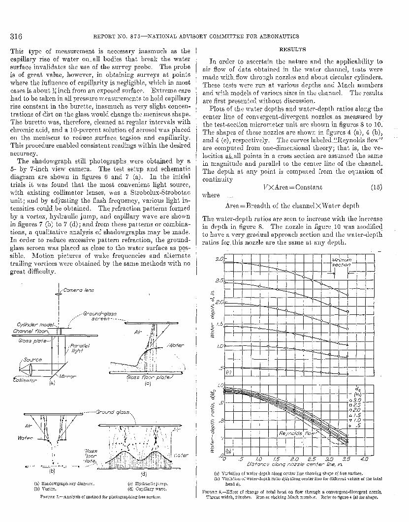
The shaclowgraph still photographs were obtai.necl by a5- by 7-inch view camera. The tesk setup and schematicdiagram are shown in figures 6 and 7 (a). In the initialtrials it was found that the most convenient light source,with existing collimator Ienses, was a Strobolux-%obotacunit; and by adjusting the flash frequency, various light in-tensities could .be obbained. The refraction patt&ns forgledby a vortex, hydraulic jump, and capillary wave are shownin figures 7 (b) to 7 (d); and from these patterns or combina-tions, a qwditative analysis of shadowgraphs may be made.k order to reduce excessive pattern refraction, the ground-glass screen was placed as close to the water surface as pos-sibIe. Motion pictures of wake frequencies and aIternatetrailing vortices were obtained by the same methods with nogreat difficulty.
!&Camera lensiI
II
,-+3round-gloss/ ‘“ screen---------
Cylhdermodel...j ;“CAar7ne/f/oor.,]‘II
i -
Glassfloor,(c)
(a) Shadowgraph ray diagre.m. (c) Hydraulic jump.(b) Vortex. (d) Capillary wave.
FIGC?RE7.—AnaIysis of method for photographing free surface,
RESULTS
In order to ascertain the nature and the applicability toair flow7 of data obtained in the water channel, tests weremade with flow through nozzles and aboui circular cylinders.These tests were run at. various depths and ikch numbersand with models of various sizes in the chau ne]. T1.w resultsare first presented lrithout discussion.
Plots of the water depths and water-depth ratios along thecenter line of convergent-divergent nozzles-as measured bythe test-section microme~er unit are shown in figures 8 to 10~The shapes of these nozzles aro shown in figures 4 (a), 4 (b),and 4 (c), respectively, The curves labele&!fJleynolds flow”are computed from one-clilr~e~lsiol]:~Itheory; thzt. is} the ve-locities a&alI_points in a cross section are assumed the samein magnitude and parallel to the center Iinc of tkc ehanrwl,The depth at any poin~ is computed from the equation ofcontinuity
VX&ea = ConstanL (15)
where
ikrea=13readth of the channe IXWater depth
The water-depth ratios are seen to increase with the incrmscin depth in figure 8. The nozzle in figure 10 was modifiedto have a very gradual approach section and the wat cr-dcp ~hratios for this nozzle are the same at any depth.
(a) Variation of water depth aIong center line showing shape of frte surfwe.(b) V8z’iationof water-depth ratio d/do along ccntcr line for different vfducs of Lhototal
bead do.
FIGURE8.—Effect of changeof total hmd on flow through a conwrgfmt-dirergcntnozzkThroat width, !2inches. Run at choking >fach number. Refer to figure 4 (a) for shape.

LY ANALOGY BETWEEN ‘iv
I I
I ii I[iI
‘ii ii ii(=41 Ill 1111111.:7 f 2 3 ~ 56 T 8
2.5?oriceda-q mm k- [kg, h.
(w Variation of w3ter depth along center line showirugshwe of free mrhce.(b) T“ariation of water-depth ratio d:lt nkmg center Iine for diEt?rent ~afues of the total
head de.
FLwE~ 9.—Ei%et of change of total hexl onflowtbmugh a eonvwgent-dir.werd nozzle.Throat width, 4 inches. Run at choking Waeh number. Refer to Egure 4 (%)for shape.
The wu-;ation with total head of the water depths andwater-depth ratios about a circular qdincler as measured bymeansof thepressure orifices and burettes is showmin frgure 11.In this case the depth ratios decrease with increase in waterdepth. .& comparison between micrometer and burettemeasurements. is show-n for a 2-inch nozzle in figure 12, whereit is seen that. the micrometer readings are greater than theburette readings ancl the difference increases with depth.
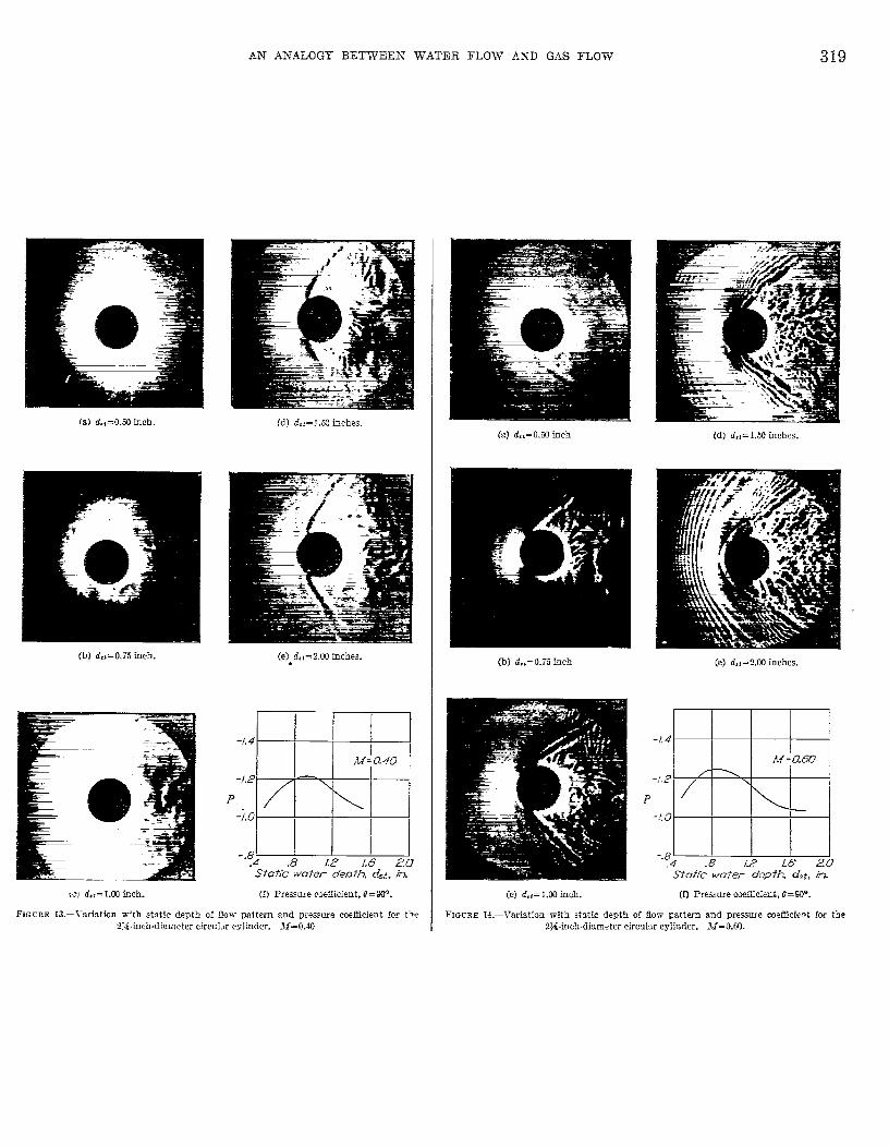
Figures 13 ancI 14 show the variation with water depth ofthe shado~graphs of the flow- about a 2;&inch-diametercircular cylinder at. Mach uumbers of 0.40 ancl 0.60, respec-tively. The corresponding variation of pressure at 0= 90° isako shown. Mditional shadow-umaphsof the flov shout circu-lar cylinders of -rarious sizes and with various water depths areshown in figures 15 to 19. The pressure distributions about.the 2~-inch circular cylinder in the water channeI with astatic depth of % inch are compared for various Mach numbersin figure 20 with the pressure distributions about a }&inclacircular cylinder iu air. The data for the circuIar cyIinderin air mere available from tests made in the Langley rectangu-Iffr high-speed tunuel.
With wmious sizes of circular cylinders in the test sectionthe wria.tion of the local Mach numbers aIong the channelwall for different stream Mach numbers is shown in figures 21to 24, and the corresponding stream depths d, and totaIhe~ds do are given in figure 25.
DISCUSSION
Various factors in3uence the resuIts obtained in the ~aters~3026—5~W
‘ATER FLOW AND G.AS FIIOW 317
-ti- 1-g-# 1.0
I I I Illl[tlL k !1!11!1
(8) Variation of water depth aiong eerier Lineshowing shap+ of free surflce.(b) Variation of water-d@h ratio d:de ahmg center Iine for diffwenf values of the totaf
heed L&
FIGmE 10.—Effect of change of total head on flow through &convergent-divergent nozzle.ThroJt width, 4 imhes (mmlh%d approach section]. Run at choking Mach number.Refer to E_q.ue4 (c) for shape.
channel, ancl the effec~ of these factors mus~ be ascertainedbefore the channeI can be usecI for the im-estigatiori of theanalogous gas flows.
From an examination of figures 15 to 19 it is seen thatconcentric waves appear in front- of the model. The fackthat these waves do not appear in the schlieren photographs(fig. 26) of air flow taken at the Langley rectangular high-speecI tunnel s~~gesk that these waves are not part of theanaIogy.
& disturbance at some poin~ in a Iiquid generally w-ill gi~erise to t-WO teypes of wa~-es—short surf Ice-tension wawscaJled capiIIary w-ayes and co~~idera,bly Ionger gratity waves(reference 5 and pp. 353-402 of reference 6). The expressionfor the velocity of propagation of ~ater ~a~-es k
Figwe ~? is a plot of CTagainst. X for waterinch and 2.0 inches. This figure shows that
(16)
depths of 0.5~aves cannot
exist with z veIocity of propa~ation less than appro.timately0.75 foot per second. Disturbances of wa~e length less thanthat corresponding to the minimum wave velocity are termedcapillary -wa-ies since they depend primarily on the surfacetension of the fluid. Propagation velocities greater thanthis minimum velocity correspond to shorter capillary w-ayesand Ionger gravity w-a-i-es.
If G= O and d<<k, equation (16) becomes

318 REPORT NO. 87 5—NATIONAL ADVISORY COMMITTEE FOR AERONAUTICS ‘
Distancearound cylinder,in.I I 1 ! I I I I I 10 /0 20 30 40 50 60 70 f+o 90
q O&g
(d Water dwthsw determined by burette.(b) Variation of water-depth ratio @foas determined by burette for different values of
total head.
FIGuBE Il.—Effect of change of total head on burette measurements at the surface of a2%inchdiametcr circular cylinder. ,7=0.70.
and this velocity-the velocity of propagation of long gra,v-ity waves-is the basic surface wave velocity. The otherwzves defined by equation (16) are water surface wavesand are not considered in the h3~draulic analogy, Figure27 shows that changes in the water depth have littIeeffect on the velocity of propagation of waves for wavelengthsless than 0.1 foot.
The wave lengths of some of the standing waves appearingin front, of the models in figures 15 to 19 were measured fromthe photographs and were plotted in the inset of figure 27against the locaI velocity (equal, for standing waves, to thevelocity of propagation) at the point where the wave occurred.This pIot showed that these waves were capillary waves.The. check marks on the inset show the number of readingsthat fall on the plotted points. These capiIlary waves,although they have no part in the hydraulic analogy, havetwo adverse effects on the application of the analogy, namely,
.78
&%
-.74$5L
& 70
4
.660.4 .8 /2 L6 20 24 28 S2
Tofolhead do,in.
A.kcromeferreudihg,in.
(a) Variation with total hmd do of water-depth ratio measured by buretk andmicrometer.
(b) Comparison of micrometer and burette readings ofdepth.
FIGURE12.—Comparison of micrometer and burette mer!-surwneutsat the minimum sectionof the 2-inch nozzIe,
complication of the flow photographs and decrease in the
accuracy of the depth measurements taken with the tm~-
section probe.
The. re.suits obtained in the water channel depend to alarge extent on the depth at which the ksLs me run. l’hceffect of depth on the formation of standing capillfiry wavesis shown in figure 28. If high stream Mach numbers withou~capillary waves in the stream are to be ol.)ttiincd, a SMIOWdepth is prescribed.
The effect of clepth on the flow patterns and pressure coefl-cients about circuIar cylinders is very pronounwd {figs. 13and 14), The pressure coefficient rises to a mtiximum vrducat d,, = 0.9 inch, The decrease in pressure coefficient. at.Iower depths is believed to be due to thti eflwt. of bottomboundary layer; the decrease at higher depths is due to theeffect of the vertical accelerations. ~omparison of figures 13
and 14 with figure 26 indicates that the water flow mos~nearly c..omxponds to air flow at depths thab ~re bet,wwn0.75 inch ancl 1.0 inch.
QT &NALOGY BETWEEN WATER FLOW AXD GAS FLOW 319
(8) a’,t=o.mimh. (d) d,’=1.S3 inches,
(bI d.z=0,i5incb. (e) d.,=2.M inches..
+.4
-t.z
P
-7.C
-.6
Ir!p
=M= O.a
.8 [2 [6 20StoTicwa+er deot~ d,~,in.
(f) Pressue coefficient, ff=9W.
FIGCEE 13.—Variarion w-ith static depth of now- pattern and pressure coeffieieni for the:V4.mchdia meter circuh- cxliider. M=O.40.
(a) d.,=0.Wimh (d) d,i=l.winches.
(b) d,:=o.ziinch
-/4
-.’. 2
P
-.’.G
-.8
(c] da,=l.CBimh.
(e) d, L=2.03 inches.
M=&Lm
/= >
.8 [2 .16’ 25‘toiicwufer depfh d,~,in
(f) Pref.sure axficient, 8=9”.
FIGCRE 14.—TcricJion with st3tic depth of flow pattern and pre.wre mefticimt for the?.X-inch.diameter eircalw cylinder. jf=o.m.

320 REPORTXO. 872 ‘—NTATIONALI ADVISORY COMMITTEE FOR AEROA7AUTICS
(a)M=O.23.
(b) M= I).41.
(c)fif=o.67.
(d) M= O.74.
($) A4=o.w.
(f) M=O.W. .
FIOUFiE 15.—Shadowmaphs of flow abont the0.30-ineMiiiameter circular cyliidc:.
Stat[c \vater dcl.th, 1.00inch.
(&)M= O.J1.(d) M=o.cf).
(b) M= O..XJ.@ M==o.71.
-.,.’ .
(cl .?=0.55.(f) M=o.77.
. .
FIQL?RE 16.—Shado\!”WWhs of flow aboutthe 1%-inch-diameter circular cyllndw.
Static water depth, 0.78 iINh.
AN .H.ALUGY BETWEEN- WATER FLOW ANT GAS FLOW
(a] M=034.
(m}M=O.46.
(c) 3“=0.YJ.
(d) U=O.M.
(e) M=o.72.
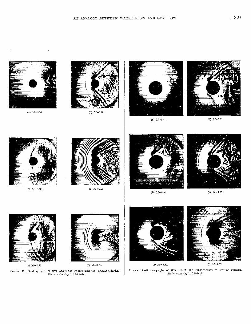
FIGCBE 17.-SSowgm.phs of tiow abautthe IMncI+diameter circdar cylinder.Static water depth, l. COincb.
(a) .lf=o.41. (d) -31=0.61.
(b) 31=0.51. (e)X=OA5
(c)M= 0.55. (f) M=O.7L
FIGLXS W-Shadowxrapha of tKow about the Z}4.~ncbWSmPfm circular cyIInder.
Static water depth. 0.75 inch.

322 REPORT NO. 87 .5-NATIONAL AD I’ISOFCY COMMITTEE FOR AERONAUTICS
(a) M=O.36. (d) .kf=0,55.
(b) .11=0 .40. (e) M=O,W.
(c:) J!f=o.49.
1,’IGURE 19.—Shado!rmii)hs of fIow about
(f) M=o.il.
the 2)4-inch-diameter circular cvlinder.Static water depth. I.!X inch.
The water is accelerated from the tottd head where thefluid velocity is zero to a value of zero acceleration ancl ma.ti-
mum veIocit.y in the test section. The motion of the waterthrough this cycle is actuat,ecl by the force of gravity whichis thus the important factor in the hydraulic analogy. If anobstruction is placecl in the path of a fluid at. constant veloc-ity, 10CEJficceIerations of flow must take place in the field&bout the obstacle. If these accelerations are large, the
vertical comport ents, which have no part in the analogy, areno longer negligible in comparison with the acceleration ofgravity; and a distortion of the flow results. This distortionis such that in a region of increasing deceleration, such asthe region in which the flow is approaching stagnation, thedepth is usually less than thtit required in the analogy; anclthe depth indicated by the pressure in the static orifices isgreater than the true depth. In a, region of increasingacceleration the opposite effects occur. The vertical accel-eration depenck upon the water depth ancI upon the slopeand curvature of the free surface.
If the water depth is increased for two cases of the same
strecim Xlkch number, the slope and curwture of the freesurface are Iikcnvise greater. This variation is shown in thefollowiug table in which the value of d, is compllt(d from
The slopes ancl curvatures of the free surface are approxi-mately proportional to the trerm ch—d,, anti the highervalue of that term therefore corresponds in general to greatervertical accelerations. An illustmtion of the foregoir~gstatements is given by the results of the nozzIe tests in which,as the. water depths clecrease, the depth’ rat ios approarhthose calculated by Reynolds flow (fig. 8); all tests weremade at dlOliiIlg Mach number. Binnici an{l H()()lierobserved the same effect (reference 3). If the dope of thefree surface is small and if the nozzle is so shaped that theacceleration in the entrance can be kept sufficiently small,no variation of water-depth ratios occurs with changingdepth (fig. 10). The same effect is shown in figures 11 and12 as measurecl by static orifices and burettes,
The effect of vertical accelerations on clepth ratios clctcr-minecl by means of static orifices is opposite to that obtainedby the probe. It may be assumed therefore thtit this cui-verse eflect WOUICIbe negligible when the two methods ofreacling pressures coincicle. The reaclings taken at the mini-mum section of the 2-inch nozzle (fig. 12] coincided when thedepth was recluced to 1.3 inches. If the free surface slopehad been more abrupt. (smaller model or modd having asharp pressure rise), a still shaIIower depth would have beenrequired to attain this condition; therefore hirge modrlsand smal~ cIepths should be employed. The minimum cIcI)this limited, however, by the effects of the lwunclary layer onthe floor.of the channeI.
The development of’ the boundary I&yer produces a veIocitygradient along the channel similar to the graclien t in a windtunnel. This effect can be compensated in the wnc way bycliverging the walls or in the case of the water chan]wl bysIoping the floor downwarcl in the direction of flow. ib effwtfor which compensation does not appear feasible is t}ythickening and thinning of the boundary layer in regions ofdecelerating ancl accelerating flow about u mocdeli ljcl~aviorwhich causes a ciistortion of the velocity distribution such aswould coxresponcI qualitatively to a thinning of the model.These boundary-layer effects are particularly serious in thewater cl.mrme] because of the appreciahlc boundary-layer dis-placement thickness (founcl to be of the order of 0.1 in.) incomparison with the total depth of the fluid. The boundary-Iayer effects multi obviously be minimized by increasing thewater depths, both because of tbe incrcasccl ratio of to [alclepth to bounclmy-layer displacement thickness and hmauseof the increased ReynoIck numbers corresponding tu [hehigher velocities with given lfach numbers. This require-ment. is, unfortunately, inconsistent with the minimizing ofthe effects of the capillary waves and of th ver~icalaccelerations.

AN A2NALOGY BETWEEN WATER FLOW’ AND GAS” FLOW 323
(s)M=UL (b) M= O.SI.(c) >1=0.61. (d) .M=Q.71.
FIWEE 20.- CompXi.wn of pressuredistribut iom abut a 2}&iuch circukr cylinder in the water chameI tith the pressure Mstrihutions &hut a Winch circular cylhdw in theLangley rectan@m high-speed tunnel (REIST).

324-- REPORT NO. 87 5—NATIONAL ADVISORY COMMITTEE FOR AERONAUTICS
*/.0 0 Oy8A -
Y “-- a G ~ -
.9
.8
A -e ~ — — ~ — — — - — ~ — “.74-
x~.7
~c+.<>.6*.,.83
5
— u 0 L’ * ‘+
>40 .-4/
,3
Cyfindeq0- Iti I “ ‘.4’,
L 0.2— p
0 0 .2+9
4 8 12 16 20- 24 28Dis fcfflce 0/Onq +es f Se c i$on, h
FICURE 21,--l’ariation or Iocal Mach number along channel wall with a 0.3-hicb-dia.metercircular cylinder.
!17he analogy is further limited by the fact that it appliesfor a hypothetical gas having a vrJue of y=2.o; the effect ofthis limitation has not been completely determined. Theeffects shown in figures 1 and 2 are not very hwge, however,and can be taken into a,ccouni in the imt,erpretation of cktataken in the water channel. CNber irmestiga tions suggest thatthe influence of the value of y in subsonic compressible flowis not great. Kaplan (reference 7) thus found that to thethird approximation the effect of the value of y in the con~-pressib]e flow up to the critical speed was negligible andVon Kfirmtln (reference 8) obtainecl a widely used expressionfor change of pressure coefficient, with hfach number by usingthe assumption y= — 1. For supersonic ffOW, the character-
istie.s curves are considerably irduen.ced by the wdue of y.The ratio of maximum velocity to the velocity of sound isgreater with 7=1.4 than with 7 =2.O; and for a given changein flow angle, the velocity change, as determined by thecharacteristics method, is also greater.
Tlw Reynolcls numbers in the water channeI m-e calcuktedfor complete submersion and are very low; the maximumvalue of R for the 2}i-inch-diameter cylinder with a staticwater de.pth of 0.75 inch is 15,000. The comparison of thewater-channel and wind-tunnel data (figs. 15 to 19 and 26,)showed that, although the cylinder -t-ests were made at
f. f — — — — — — - — — — –M
00.775D ,620 .41
[.0— -A .40
.9 — — — — — —
L —
%&.8 6
/
~
9 .-
<e8.7 — — — — — ~ — — — — — — —s>
/ -a-..
2 ❑ - -4
.6
.5 — — — — — — — — — —— — —– ----—
...-
0 0 “ ~.4
w&
&
r----..,.Qyfinder
.3 i [4 8 /2 [6 m 24 28
Dkkmce o/ongfesi secfhn,in.
FIGCIZE22.—Variation of local Mach number along channel wall with t 1M-intb-diarnctcrcirmdnr cylinder.
considerably higher Reynolck numbers in air than in wa h:r, thesame type of flow occurred in both cases; the main mnsid-eration’ is agreement of the flow patterns rather than iclenLicnlReyno]cls numbers.
ln a wind tunnel, a choking or maximum stream }iachnumber occurs wkn locaI hlach numbers of 1.00 CXLCDCLacross the section be~wcen the model and tunn@l wcdk. ~~.
similar eff eci was noted in the water chanuel. .Tigurc 25shows that the stream depth decreases and the total headincreases lvith Jlach number up to a maximum value that
depends on the size of the model tested. At this choking
condition both the stream clepth WK1 the total hwd increase
with an additional power input,. l?igum 29 shows the maxi-
mum Mach number for various ratios of cylinder ditimctcr hchannel width. Variation of the data from the [hwreticalcurves might be expected inasmuch M the theoretical valueswere computed by one-climensional theory (Reynolds flow);whereas, the actual flow is two-dimensional, Llaximurnhfach numbers that occur in wind tunnels, however, agreemuch more closely with the one-climensiorud theory thun do
those shown in figure 29 (see reference 9); ancl it ihereforcseems likely that the clivergence is clue to other factors, suchas boundary-layer effects and vertical accelerations, ratherthan to the two-dimensional nature of the flow-.

.+.lv .DTALOGY BETWEEN WATER FLOW AIND GAS FLOW 325
D[s+ance dcng k=-+ secff’m, h.
FIGURE 23.-%-ariatiou of kwal Mmh number along chwme] wall with& 2}i-inchdIametereirculm crLindcr.
The disturbance aIong the charmel waII with wrious sizecylinders in the test section is show-n in figures 21 to 24.The w-ail disturbance is an indication of the severity athigh Mach numbers of channe}-waII or mind-tunneI-waIIinterference. As the stream Mach number approaches 1.00,the wall disturbance increases untiI at the choking concLitionthe interference becomes large e~en for the smallest. cylinder.For the 1%-inch-cliameter cyhder (fig. 2~), the point ofsotic velocity tt the WW is located approxhnate~y 3 diametersbehind the cylinder. This result is in agreement with theflow photographs (figs. 15 and 17), which show a g@l--i-ring-shaped shock starting from the regiou behind the cylinderand extending downstream toward the -walls. Figure 30shows the lines ‘of constant Mach number in the flo-w fieldabout a 6-inch-diameter cylinder at choking Mach numberarid show-s clearly the supersonic flow o ccurrtig b etidthe cylinder.
.1 comparison of the shadowgraphs (figs. 15 to 19) withschlieren photographs of flow about circular cylinders in air(fig. 26) shows that the two flows are Yev similar. The typeof fio-ir is the same in the two cmes and is the type that ischaracteristic of Reynolds numbers somewhat below- thecriticaI -ralue. At Reynolds numbers between 50 and350,000, an unstable condition is set up behind a circular
Lo bM
00.50
0 .2[-9
.8
F~-.7 / {
jc~b.6s>;.! + A
.4
.% I v8 12 [6 20 24
D[s+anceo.bngfes+seefrii,in.
FIGIXE 24.—Variation of local ?Jsch number aIong cfmmeI TW.11with a 6-inchdiamd er&culwcylinder.
cylinder in which vortices are shed aIterrtateIy from eachside. Laminar separation occurs at a point approximately80” from the forward stagnation point and a vortex sheet isformed which extends downstream ancl finally rolls up intoa large ~ortex. The vortices so shed arrange themselvesinto a K&m6n street- (See reference 6, pp. 217-218.)
Si+-eamLfochwmber, M
FIGCBE 25.—Variation with stream Meeh nmnber of stieem depth and tokd hewl withcircular cylinders in the te+itsection. d.,=1.C4inch.

326 REPORT NO. 8 75—NATION’AL ADVISORY COMMITTEE FOR AEROhrAUTICS
(a) M=0,401; R=216,~; D=l,O inch. (d) .Vf=O.730;R=337,0t@ D=l.O inch.
(h) kf=0,@30; 2?=296,~ D=LO inch. (e) .tf=O.3SO; R=73,ccxI;D=0,2 inch.
(c) J!f=O.629; R=308,WO; B=l.O inch. (f) M=OMU; R=73,WO; 2)=0.2 inch.
(Same as (e) sbowhIg extended field.)
FIGURE 26,—SchIieren photographs of circuku’ cyIinders in the Langley rectsngulcr high-SDCed tUIIIIel.
301 ‘,, .~:m’— —
“ 25QI
/“
b- 1‘, /
S’20- ---’d =20 in./’,.. 10 ~
‘5-1,0 ‘ Illi I ‘~
I I I I I I I I I A
o .2 .4 ,6 .8 1.0 L2 1.4 /.6 /.8Wove [engtlj~,ft
FIGURE 27.—Variation of ~elocity of propagation of water surface waves with wave length.
Figures 16 (s), 18 (a), 19 (b), and 26 (a) show this type offlow, which is the same in the water channel as in the air
flow. Because of the occurrence of sepamtion, the nctualpressure distribution is dtiercm~ from tha~ calcu]atcd bypotentigl-flow theory. The actual pressures over the for-ward part of the. c.ylincler are higher and those over the rrarare lower than those calculated by theory. ‘1’he. mgativepressure peak is greatly reduced. Figure 20 SLOWSthe pressuredistributions about circular cylinders in air and in thewater channel. The quantitative results obtained in thewater channel are very close to those ob[ainecl in air(figs. 20 (a) to 20 (c)). This CIOSCagreemeni is believed, l~ow-ever, to be Ia.rgely fortuitous, resulting from an interact iollbetween the bottom-boundary-layer effects and the ratherlarge channeI-wall interference in ihe water channeI. At thechoIiing kfach number M=O.71 in the wa~er chauncl (see
fig. !20 (d)), the interference effects exceecl the relievingeffects of the thinning of the boundary layer, and the nclgn-tive pressure coefficients near t?= 90° mcecd those obtainedin the wind tunneI.
Because of the unsteady nature of the flow, instantaneousvelocities greater than those indicated by the pressure dis-tributions occur near the surface of a cylinder, TILCcritiralspeed may therefore be expected to be lower than indicatedby the pressure distributions, an effect that has been observedin air. Figure 2 shows that with a given pcaIi negativepressure coefficient the. critical Tlach number should besomewhat lower in the water channel (-y= 2.0) than in air(7=1.4).
Another effect of the unsteady flow is the asymmet.ricaidevelopment of shock. When the flow CIOSCSin on one sideof the cylinder, the induced velocities incrcasc and the localhlach number may exceed 1.00. A shock wave may thus
form ou one side while none exists on the other or a moreintense shock may exist on one side than on tho other. Suchasymmetrical shocli patterns are shown in figures 16 (h) to16 (d), 17 (b), 18 (b) to-18 (d), and 26 (b) to 26 (d). 13xmtlythe same phenomenon occurs in the water channel as in theair flow. In some case.s, the shedding of these wa}~cs alter-nately from each side of a cylinder has been observed in thewater channel when the stream Mach number was only aIittle above the critical vaIue. Such behavior is to he cw-pected if on one side of the cylinder the velocities firstexceed and then fall below the speed of sound as the flotvcIoses in and then breaks away from the surface. Withincrease in Tfach number, a strong disturbance originates a~the edge of the wa.lie approximately 1 cliameter behind thecylinder and extends into the field of flow (figs. 15 (d),18 (d), and 26 (d)). This disturbance oscilla.tm with the\die, which is stilI unstable, and in its incipieni stagesalternates from one sicle of the modeI to tho oth~jr. At stillhigher speed, the flow closes in behind the cylinder so tha~the cylinder has the appearance of a strccwnlim body with astrong gull-wing-shaped disturbance at ik trailing edge(figs. 15 (e), 15 (f), 16 (f), 17 (f), 18 (f), 19 (f), 26 (e), and26 (f)). These features appear to be essentially the samein the water channel as in the air flow.

AN ANALOGY BETWEEN WATER FLOW A2XD GAS FLOW 327
.7 \
\
.6 \
z\
$
&c“
$ \
$
:“ .4
.$
‘s \
.3 \
I1 ‘ “ k.\
—
.2—
o /.0 2.0 3.0 4.0 5Q 6.0Sfaficwater depfh,d~, jn.
FIGCEE 2&—Minimnm stream MWEL number at which standing capilbry wares form in free stream.
1.0
h..9
2~ .8
~c$.7
sE>.6E..
$.5
.40 .[0 .20 .30
RCIIYOof cyltir ofamefer to cbcrnefk?k’fh
FIG’CEE 2%—Water_ehanneI maximum test Mach number.
.,-Chcmnelw[l
.60
Ml =a50
— —.Flow —— -_
-—L—
FIG~BEMI.-Lines of constant Mach number in the flow field about a fi-ineh+limwter circukarcylinder in the U-inch ‘water chmmeI at maximum stream Yaeh number. M= 0.51.

328 REPORT NO. 87 5—NATIONAL ADVISORY COMEImTEE FOR AERONAUTICS
EQUIPMENT AND FUTURE DEVELOPMENT
Measurement of depth at the surface of models and atfluid boundaries are best made -with pressure orifices andburettes because of the capilIary rise, whereas the micrometermethod is suited for measurement of field depths; bothmethods agree very well provided the vertical accelerationsare small. The burette method is best for obttiining averagepressures in unstable flow. A method of photography hasbeen developed that is simple and completely satisfactory,The shadowgrapbs of the water flow me. stril<ingIy similarto the schlieren photographs of the ~ir flow.
The value of the water channeI Iies mainly in the 10W7cos~and convenience of operation. Field surveys are simplymade, and various features of the flow such as turbulence,vortices, separation, and shock formation are easily observedand photographed, Streamlines about a model are easilyobtained by inserting streams of dye in the water ahead ofthe model.
A larger channeI especially designed to minimize boundary-Iayer eflects cmd to secure uniform flow in the tesi section isclesirable. The channel should be large enough to permit testsat Reynolds numbers above the critical vaIue. A largerchannel would aIso be advantageous in reducing the adverseeffecis of the bounclary layer or vertical accelerations, or both.
.AdditionaI investigations, both theoretical and experi-mental, are neecled in orcler to determine the correctionsnecessary to convert quantities obtained from the water flowto the values characteristic of the air flow about correspond-ing bodies.
CONCLUSIONS
An experimental apparatus and technique have been de-veloped for the investigation of the analogy between waterflow with a free surface anti two-dimensional compressiblegas flow (hydraulic analogy); a preliminary investigation hasbeen macle and the results of an application of the analogyhave been presented. The following conclusions are indi-cat ed from this work:
1. The hydraulic anaIogy provides a v cry inexpensive andconvenient means of investigating high-specc] t~vo-dimen-sional air flow. The flow may be observed and photo-graphed, and surface and field measurements may be rosilyobtained. Reasonably satisfactory agreement was foundbetweem the water flow and air flow about correspondingbodies, although considerable work in both theory cd cxpcri-menfi is needed in order to convert with quantita~ive ccccu-racy from the w~ter flo~v to the flow in air.
2. With a larger channel, difficulties due to vertiml accel-erations ancl subcritical Reynolds numbers mighb be overcome.
LANGLEY lIELIORI.4L AERONAUTICAL LABORATORY,
~NTATIONAL AD VISORI- COMMITTEE FOR AEROINAUTICSi
LANGLEY FIELD, VA., August 91, 1946.
REFERENCESs
1. FLiabouchinsliy,D.: M&anique desfluic]es. Compt.esRendus, L 195,no. 22, Nov. 28, 1932, pp. 998–999.
2. Riabouchins@, Dimiiri: M4caniquc des fiuicIes. Compt.cs Rcnclus,
t. 199, ILO. 14, Oct. 1, 1934, PP. 632-634.
3. Binnie, A. M., and Hooker, El G.: The F1OTVunder (lravity of an
Incompressible and Inviscid Fluid through a Constriction in FL
Horizontal Channel. Proc. Roy. Sot. (London), ser. Al vol. 150,no. 899, April 1937, pp. 592-60S.
4. Preiswerk,Ernst: Application of the Methods of Gas Dynamics toWater Flows with Free Surface.Part I. Flows with No Energy Dissipation. NACA TM N’o.03.4
1940.Part 11. Flows with Momentum Discontinuities @Iydraulic
Jumps). NACA TM No. 935, 1940.5. Page,Leigh: introduction to TheoreticalPhysics. D. Van h’ostrand
Co., ~llC.,1928, PP. 218–224.6. Rouse; Hunter: Fluid Mechanics for Hydraulic 12ngincc.rs.
McGraw-Hill Book Co., inc., 193%7. Kaplan, Carl: Two-Dimensional Subsonic Compressible l?low past
Elliptic cylinders. NACA Rep. hTo. 624, 1938.S. l’on K6rmctn, Th.: Compressibility Effects in Acrodynaroics.
Jour. Aero. Sci., YOI. 8, no. 9, July 1941, pp. 337-356.9. Bj-rue, Robert ‘k’.: Experimental Constriction Effects in High-
Speed Wind Tunnels. iVACA .4CR NO. IA L07a, 1944.
