user manual salto wrlud14bxx | long distance reader
TRANSCRIPT
Publications of SALTO SYSTEMS S.L. are protected by copyright and all rights are reserved. SALTO SYSTEMS publications may not be reproduced in any form or by any means without written permission from the copyright owner.
\\USER MANUAL
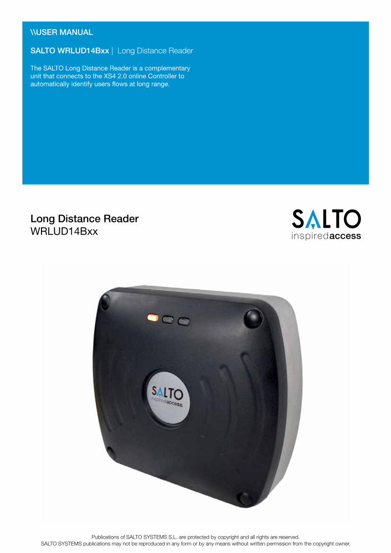
SALTO WRLUD14Bxx | Long Distance Reader
The SALTO Long Distance Reader is a complementary unit that connects to the XS4 2.0 online Controller to automatically identify users flows at long range.
Long Distance Reader WRLUD14Bxx
WR
LUD
14B
XX
-Man
ua-E
NG
-10-
16
www.saltosystems.com
SALTO Systems - WRLUD14Bxx - Long Distance Reader manual
2CONFIDENTIAL - This document contains confidential and privileged information. The reproduction of any part of the document is strictly prohibited without the prior written consent of SALTO Systems S.L.
WR
LUD
14B
XX
-Man
ua-E
NG
-10-
16
www.saltosystems.com
SALTO Systems - WRLUD14Bxx - Long Distance Reader manual
3CONFIDENTIAL - This document contains confidential and privileged information. The reproduction of any part of the document is strictly prohibited without the prior written consent of SALTO Systems S.L.
Index
1. TECHNICAL DATA 5 2. MECHANICAL DIMENSIONS 6 3. WIRING 7 4. MOUNTING 10 5. READING DISTANCE 13 6. TEST MODE 14 7. CONFIGURATION OF WEBCONFIG SOFTWARE 15
WR
LUD
14B
XX
-Man
ua-E
NG
-10-
16
www.saltosystems.com
SALTO Systems - WRLUD14Bxx - Long Distance Reader manual
4CONFIDENTIAL - This document contains confidential and privileged information. The reproduction of any part of the document is strictly prohibited without the prior written consent of SALTO Systems S.L.
Regulatory Notices
EuropeHereby, SALTO Systems S.L. declares that this equipment - if used according to the in- structions - is in compliance with the essential requirements and other relevant provisions of the RTTE Directive 1999/5/EC.
A full declaration of conformity can be requested at:
Approved for use in all European countries.
FCC Digital Device LimitationsRadio and Television Interference
This equipment has been tested and found to comply with the limits for a Class A digital device, pursuant to Part 15 of the FCC rules. These limits are designed to provide reason- able protection against harmful interference when the equipment is operated in a commercial environment. This equipment generates, uses and can radiate radio frequency energy and, if not installed and used in accordance with the instruction manual, may cause harm - ful interference to radio communications. Operation of this equipment in a residential area is likely to cause harmful interference, in which case the user will be required to correct the interference at his own expense. This device complies with Part 15 of the FCC rules. Operation is subject to the following two conditions: (1) This device may not cause harmful interference, and (2) this device must accept any interference received, including interference that may cause undesired operation. In order to maintain compliance with FCC regulations, shielded cables must be used with this equipment. Operation with non-approved equipment or un- shielded cables is likely to result in interference to radio and television reception.Caution! Changes or modifications not expressly approved by the manufacturer could void the user´s authority to operate this equipment.
FCC NoticeTo comply with FCC Part 15 rules in the United States, the system must be professionally installed to ensure compliance with the Part 15 certification. It is the responsibility of the operator and professional installer to ensure that only certified systems are deployed in the United States. The use of the system in any other combination (such as co-located antennas transmitting the same information) is expressly forbidden.
FCC Radiation Exposure StatementThis equipment complies with the FCC radiation exposure limits set forth for an uncontrolled environment. This equipment should be installed and operated with minimum distance of 20 cm between the radiator and the human body. Industry CanadaThis device complies with Industry Canada licence-exempt RSS standard(s). Operation is subject to the following two conditions:(1) this device may not cause interference, and(2) this device must accept any interference, including interference that may cause undesired operation of the device.
Le présent appareil est conforme aux CNR d’Industrie Canada applicables aux appareils radio exempts de licence. L’exploitation est autorisée aux deux conditions suivantes : (1) l’appareil ne doit pas produire de brouillage, et (2) l’utilisateur de l’appareil doit accepter tout brouillage radioélectrique subi, même si le brouillage est susceptible d’en compromet- tre le fonctionnement.
WR
LUD
14B
XX
-Man
ua-E
NG
-10-
16
www.saltosystems.com
SALTO Systems - WRLUD14Bxx - Long Distance Reader manual
5CONFIDENTIAL - This document contains confidential and privileged information. The reproduction of any part of the document is strictly prohibited without the prior written consent of SALTO Systems S.L.
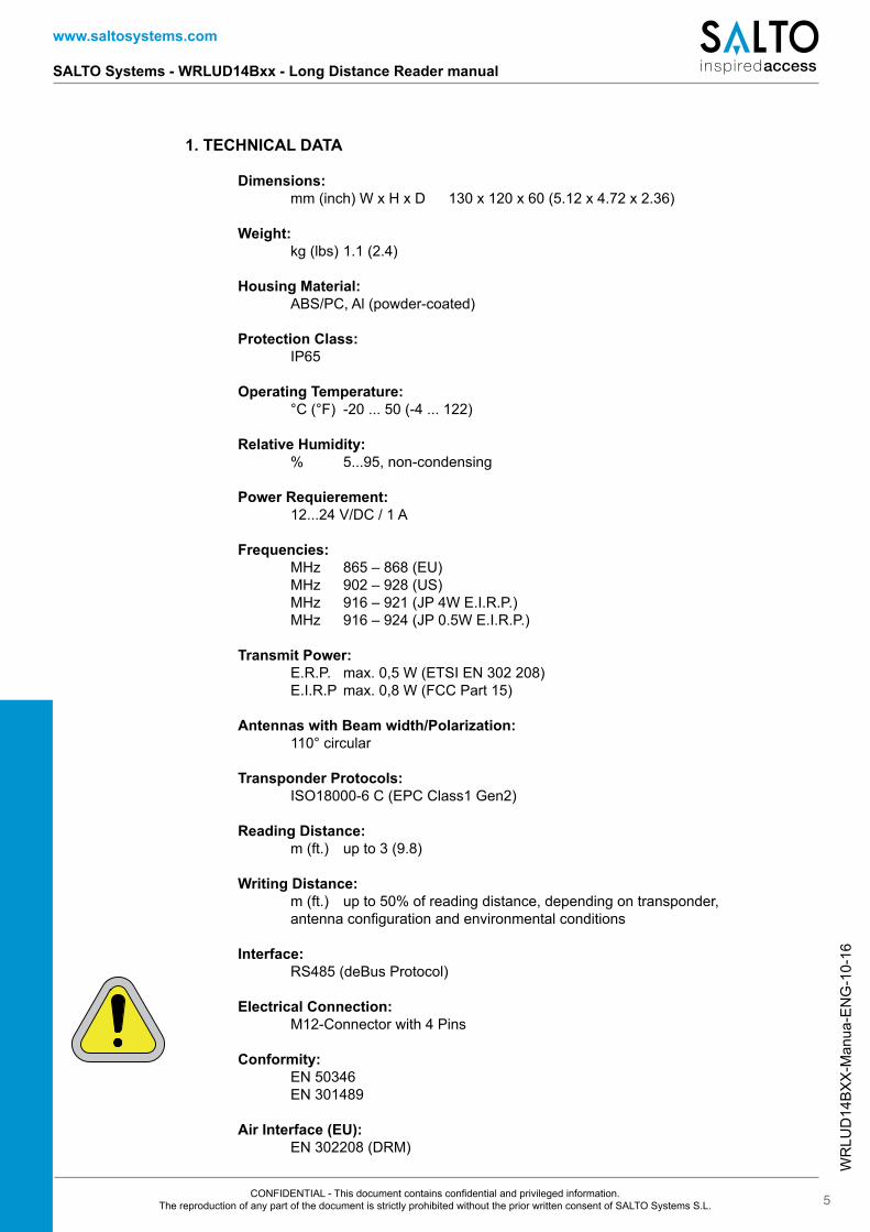
1. TECHNICAL DATA
Dimensions: mm (inch) W x H x D 130 x 120 x 60 (5.12 x 4.72 x 2.36)
Weight: kg (lbs) 1.1 (2.4)
Housing Material: ABS/PC, Al (powder-coated)
Protection Class: IP65
Operating Temperature: °C (°F) -20 ... 50 (-4 ... 122)
Relative Humidity: % 5...95, non-condensing
Power Requierement: 12...24 V/DC / 1 A
Frequencies: MHz 865 – 868 (EU) MHz 902 – 928 (US) MHz 916 – 921 (JP 4W E.I.R.P.) MHz 916 – 924 (JP 0.5W E.I.R.P.)
Transmit Power: E.R.P. max. 0,5 W (ETSI EN 302 208) E.I.R.P max. 0,8 W (FCC Part 15)
Antennas with Beam width/Polarization: 110° circular
Transponder Protocols: ISO18000-6 C (EPC Class1 Gen2)
Reading Distance: m (ft.) up to 3 (9.8)
Writing Distance: m (ft.) up to 50% of reading distance, depending on transponder, antenna configuration and environmental conditions
Interface: RS485 (deBus Protocol)
Electrical Connection: M12-Connector with 4 Pins
Conformity: EN 50346 EN 301489
Air Interface (EU): EN 302208 (DRM)
WR
LUD
14B
XX
-Man
ua-E
NG
-10-
16
www.saltosystems.com
SALTO Systems - WRLUD14Bxx - Long Distance Reader manual
6CONFIDENTIAL - This document contains confidential and privileged information. The reproduction of any part of the document is strictly prohibited without the prior written consent of SALTO Systems S.L.
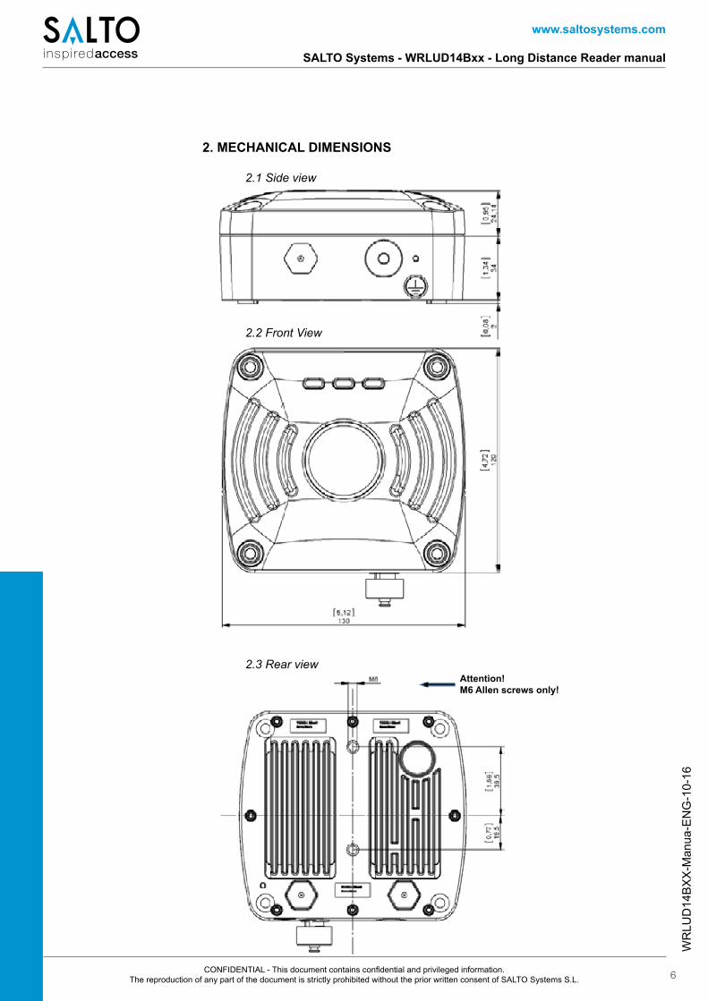
2. MECHANICAL DIMENSIONS
2.1 Side view
2.2 Front View
2.3 Rear viewAttention!M6 Allen screws only!
WR
LUD
14B
XX
-Man
ua-E
NG
-10-
16
www.saltosystems.com
SALTO Systems - WRLUD14Bxx - Long Distance Reader manual
7CONFIDENTIAL - This document contains confidential and privileged information. The reproduction of any part of the document is strictly prohibited without the prior written consent of SALTO Systems S.L.
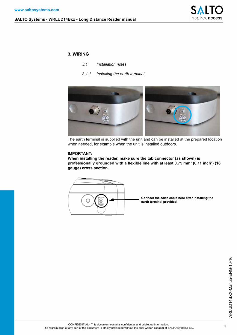
3. WIRING
3.1 Installation notes
3.1.1 Installing the earth terminal:
The earth terminal is supplied with the unit and can be installed at the prepared location when needed, for example when the unit is installed outdoors.
IMPORTANT: When installing the reader, make sure the tab connector (as shown) is professionally grounded with a flexible line with at least 0.75 mm² (0.11 inch²) (18 gauge) cross section.
Connect the earth cable here after installing the earth terminal provided.
WR
LUD
14B
XX
-Man
ua-E
NG
-10-
16
www.saltosystems.com
SALTO Systems - WRLUD14Bxx - Long Distance Reader manual
8CONFIDENTIAL - This document contains confidential and privileged information. The reproduction of any part of the document is strictly prohibited without the prior written consent of SALTO Systems S.L.
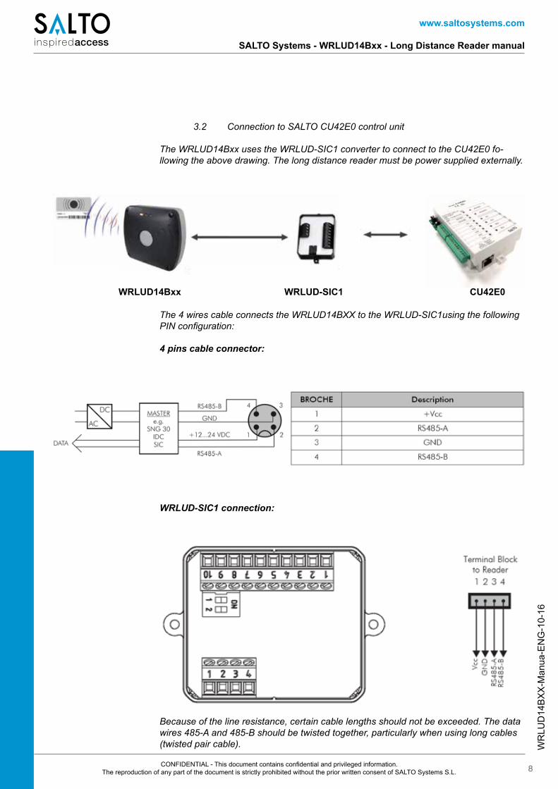
3.2 Connection to SALTO CU42E0 control unit
The WRLUD14Bxx uses the WRLUD-SIC1 converter to connect to the CU42E0 fo-llowing the above drawing. The long distance reader must be power supplied externally.
The 4 wires cable connects the WRLUD14BXX to the WRLUD-SIC1using the following PIN configuration:
4 pins cable connector:
WRLUD14Bxx WRLUD-SIC1 CU42E0
WRLUD-SIC1 connection:
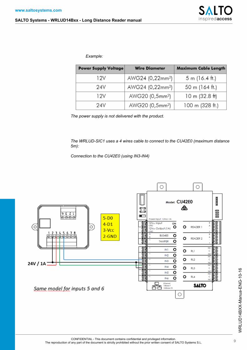
Because of the line resistance, certain cable lengths should not be exceeded. The data wires 485-A and 485-B should be twisted together, particularly when using long cables (twisted pair cable).
WR
LUD
14B
XX
-Man
ua-E
NG
-10-
16
www.saltosystems.com
SALTO Systems - WRLUD14Bxx - Long Distance Reader manual
9CONFIDENTIAL - This document contains confidential and privileged information. The reproduction of any part of the document is strictly prohibited without the prior written consent of SALTO Systems S.L.
Example:
The power supply is not delivered with the product.
The WRLUD-SIC1 uses a 4 wires cable to connect to the CU42E0 (maximum distance 5m):
Connection to the CU42E0 (using IN3-IN4)
WR
LUD
14B
XX
-Man
ua-E
NG
-10-
16
www.saltosystems.com
SALTO Systems - WRLUD14Bxx - Long Distance Reader manual
10CONFIDENTIAL - This document contains confidential and privileged information. The reproduction of any part of the document is strictly prohibited without the prior written consent of SALTO Systems S.L.
4. MOUNTING
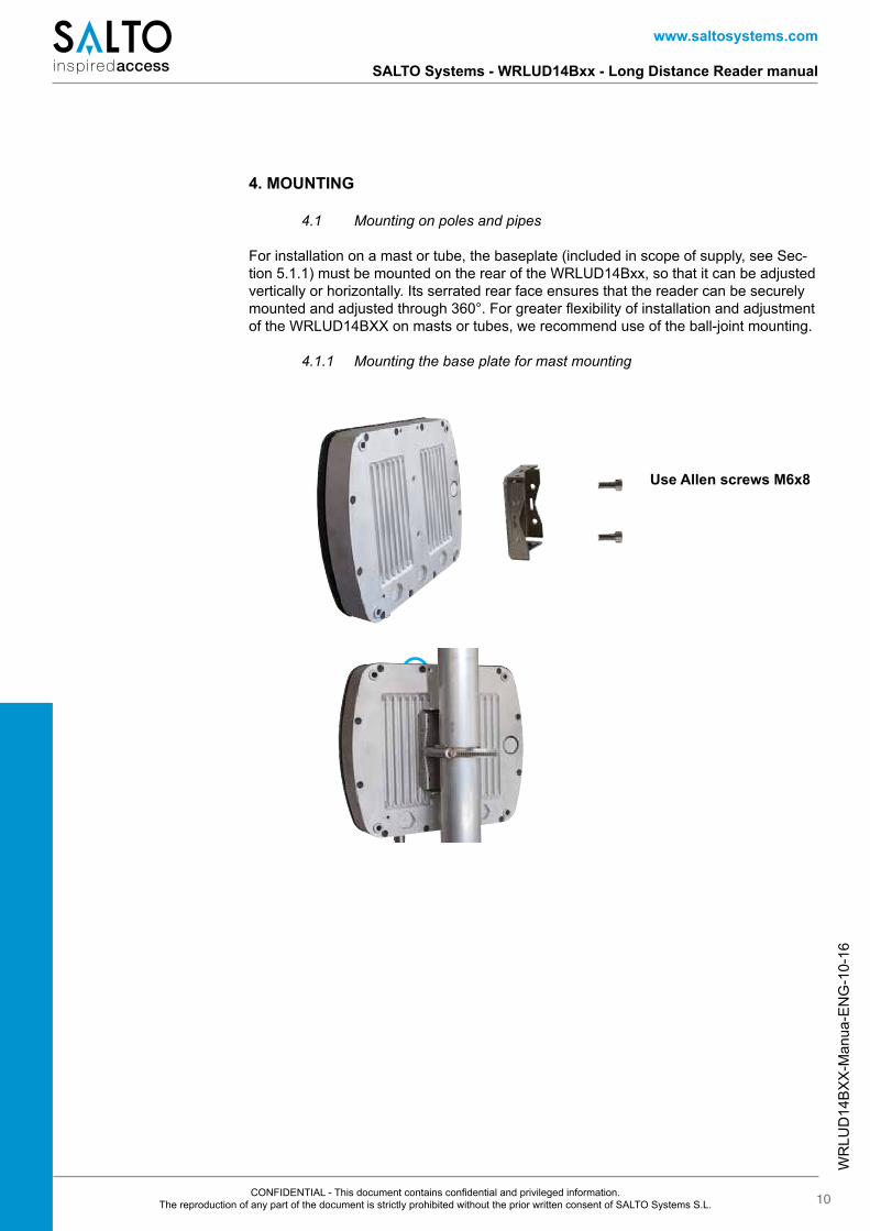
4.1 Mounting on poles and pipes
For installation on a mast or tube, the baseplate (included in scope of supply, see Sec-tion 5.1.1) must be mounted on the rear of the WRLUD14Bxx, so that it can be adjusted vertically or horizontally. Its serrated rear face ensures that the reader can be securely mounted and adjusted through 360°. For greater flexibility of installation and adjustment of the WRLUD14BXX on masts or tubes, we recommend use of the ball-joint mounting.
4.1.1 Mounting the base plate for mast mounting
Use Allen screws M6x8
WR
LUD
14B
XX
-Man
ua-E
NG
-10-
16
www.saltosystems.com
SALTO Systems - WRLUD14Bxx - Long Distance Reader manual
11CONFIDENTIAL - This document contains confidential and privileged information. The reproduction of any part of the document is strictly prohibited without the prior written consent of SALTO Systems S.L.
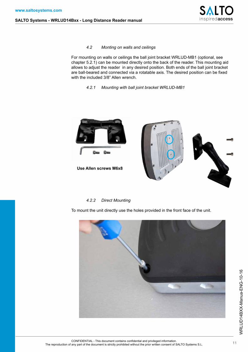
Use Allen screws M6x8
4.2 Monting on walls and ceilings
For mounting on walls or ceilings the ball joint bracket WRLUD-MB1 (optional, see chapter 5.2.1) can be mounted directly onto the back of the reader. This mounting aid allows to adjust the reader in any desired position. Both ends of the ball joint bracket are ball-beared and connected via a rotatable axis. The desired position can be fixed with the included 3/8” Allen wrench.
4.2.1 Mounting with ball joint bracket WRLUD-MB1
4.2.2 Direct Mounting
To mount the unit directly use the holes provided in the front face of the unit.
WR
LUD
14B
XX
-Man
ua-E
NG
-10-
16
www.saltosystems.com
SALTO Systems - WRLUD14Bxx - Long Distance Reader manual
12CONFIDENTIAL - This document contains confidential and privileged information. The reproduction of any part of the document is strictly prohibited without the prior written consent of SALTO Systems S.L.
4.3 Function Principle and Environmental Influences
The reader sends a high-frequency carrier signal. The transponder that is located within the area of this transmitted carrier transmits the signal back with its own transponder data in a modulated way. This very weak signal is being analyzed by the reader.Because of the particular small-bandwidth and the high carrier frequency this system is almost fail-safe. Nevertheless the range of the reader can be negatively influenced. The following list shows what to pay attention to:
1. The reader must have visual contact to the transponder. There must not be any walls or other devices between reader and transponder. Reading through plastic film, card board, papers or glass windows may be possible, but will reduce the rea-ding range depending on the condition of the material.
2. Water, ice and snow will absorb the carrier signal. Therefore the installer has to make sure that the front of the reader and the transponder is not covered with wa-ter, ice or snow.
3. Reflections within the surroundings of the reader can influence the reading result in a negative way. Therefore the reader should be mounted as free-standing as possi-ble. We strictly discourage from sunk-in installations.
4. In Multi-Reader Environment (EU only), you must assign different channels to the readers. To accomplish this, the parameter “preferred channel” should be adjusted accordingly and you have to choose the highest possible channel spacing! When using UHF readers that are installed close together (e.g. entrance and exit lane) it is recommended to pair channels such as Channel 4, 10 and channel 7, 13 etc.
WR
LUD
14B
XX
-Man
ua-E
NG
-10-
16
www.saltosystems.com
SALTO Systems - WRLUD14Bxx - Long Distance Reader manual
13CONFIDENTIAL - This document contains confidential and privileged information. The reproduction of any part of the document is strictly prohibited without the prior written consent of SALTO Systems S.L.
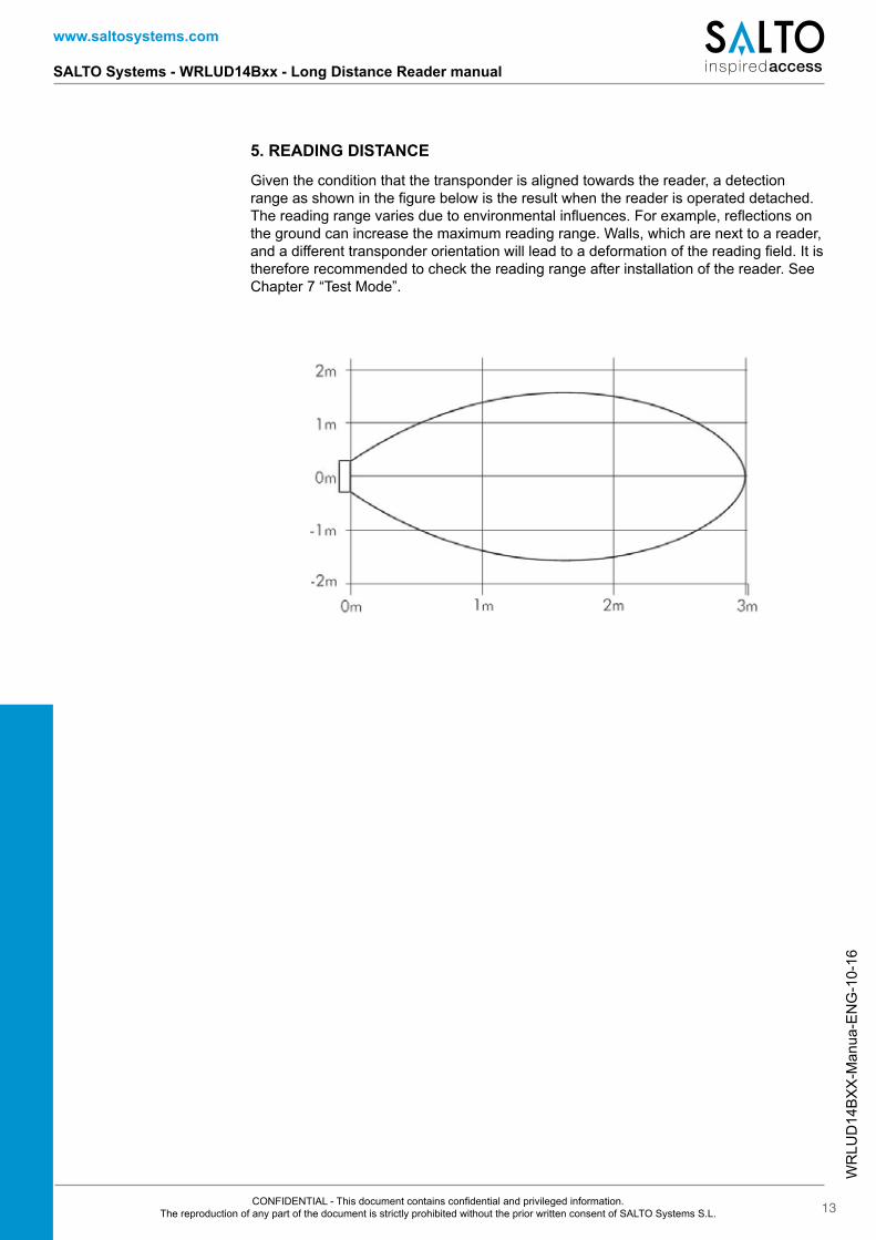
Given the condition that the transponder is aligned towards the reader, a detection range as shown in the figure below is the result when the reader is operated detached. The reading range varies due to environmental influences. For example, reflections on the ground can increase the maximum reading range. Walls, which are next to a reader, and a different transponder orientation will lead to a deformation of the reading field. It is therefore recommended to check the reading range after installation of the reader. See Chapter 7 “Test Mode”.
5. READING DISTANCE
WR
LUD
14B
XX
-Man
ua-E
NG
-10-
16
www.saltosystems.com
SALTO Systems - WRLUD14Bxx - Long Distance Reader manual
14CONFIDENTIAL - This document contains confidential and privileged information. The reproduction of any part of the document is strictly prohibited without the prior written consent of SALTO Systems S.L.
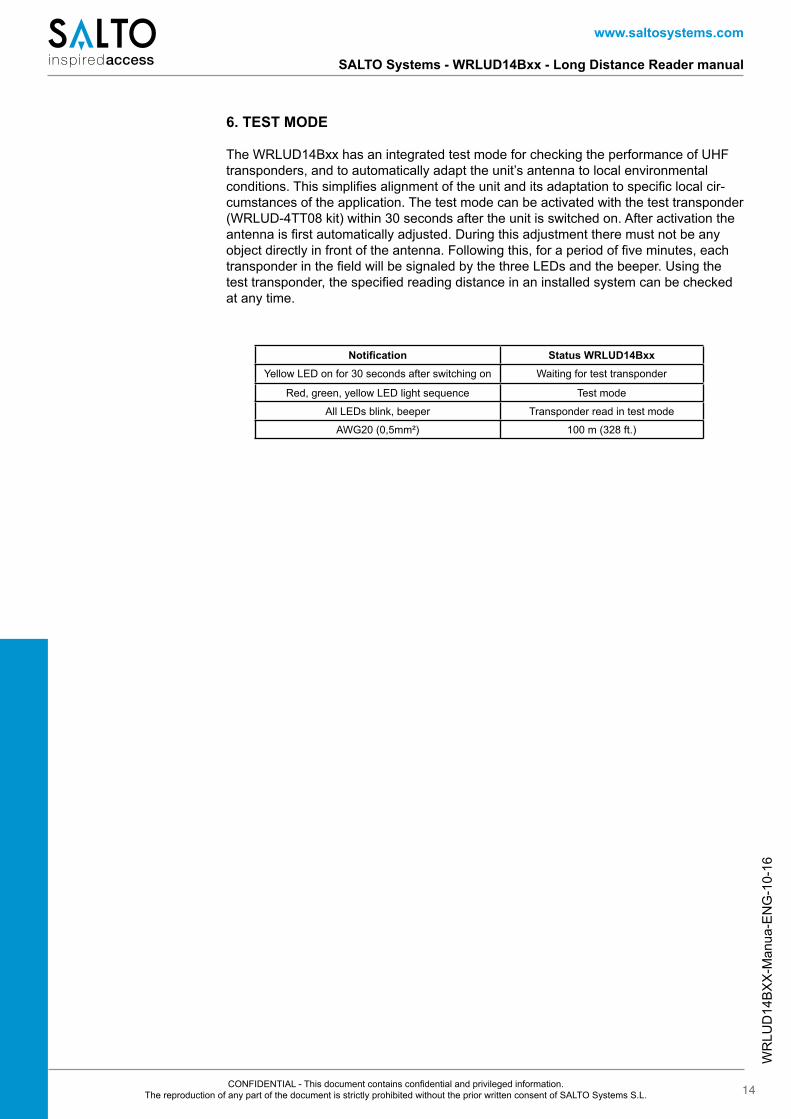
6. TEST MODE
The WRLUD14Bxx has an integrated test mode for checking the performance of UHF transponders, and to automatically adapt the unit’s antenna to local environmental conditions. This simplifies alignment of the unit and its adaptation to specific local cir-cumstances of the application. The test mode can be activated with the test transponder (WRLUD-4TT08 kit) within 30 seconds after the unit is switched on. After activation the antenna is first automatically adjusted. During this adjustment there must not be any object directly in front of the antenna. Following this, for a period of five minutes, each transponder in the field will be signaled by the three LEDs and the beeper. Using the test transponder, the specified reading distance in an installed system can be checked at any time.
Notification Status WRLUD14BxxYellow LED on for 30 seconds after switching on Waiting for test transponder
Red, green, yellow LED light sequence Test mode
All LEDs blink, beeper Transponder read in test mode
AWG20 (0,5mm²) 100 m (328 ft.)
WR
LUD
14B
XX
-Man
ua-E
NG
-10-
16
www.saltosystems.com
SALTO Systems - WRLUD14Bxx - Long Distance Reader manual
15CONFIDENTIAL - This document contains confidential and privileged information. The reproduction of any part of the document is strictly prohibited without the prior written consent of SALTO Systems S.L.
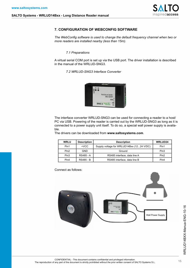
The interface converter WRLUD-SNG3 can be used for connecting a reader to a host/PC via USB. Powering of the reader is carried out by the WRLUD-SNG3 as long as it is connected to a power supply unit itself. To do so, a special wall power supply is availa-ble.The drivers can be downloaded from www.saltosystems.com.
Connect as follows:
WRLU Description Description WRLUD24Pin1 +VCC Supply voltage for WRLUD14Bxx (12...24 V/DC) Pin1
Pin2 GND Ground Pin3
Pin3 RS485 - A RS485 interface, data line A Pin2
Pin4 RS485 - B RS485 interface, data line B Pin4
7. CONFIGURATION OF WEBCONFIG SOFTWARE
The WebConfig software is used to change the default frequency channel when two or more readers are installed nearby (less than 15m).
7.1 Preparations
A virtual serial COM port is set up via the USB port. The driver installation is described in the manual of the WRLUD-SNG3.
7.2 WRLUD-SNG3 Interface Converter
Wall Power Supply
WR
LUD
14B
XX
-Man
ua-E
NG
-10-
16
www.saltosystems.com
SALTO Systems - WRLUD14Bxx - Long Distance Reader manual
16CONFIDENTIAL - This document contains confidential and privileged information. The reproduction of any part of the document is strictly prohibited without the prior written consent of SALTO Systems S.L.
7.3 Starting WebConfig
Download the WebConfig software from www.saltosystems.com.Run the WebConfig software. Copy the file “WebConfig.exe” into a suitable directory on your local hard disk and open it by double-clicking.
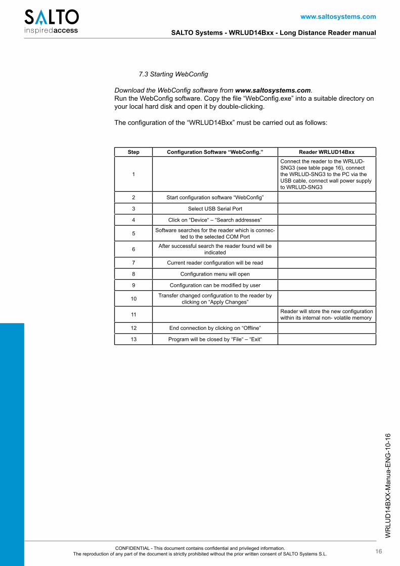
The configuration of the “WRLUD14Bxx” must be carried out as follows:
Step Configuration Software “WebConfig.” Reader WRLUD14Bxx
1
Connect the reader to the WRLUD-SNG3 (see table page 16), connect the WRLUD-SNG3 to the PC via the USB cable, connect wall power supply to WRLUD-SNG3
2 Start configuration software “WebConfig”
3 Select USB Serial Port
4 Click on “Device“ – “Search addresses“
5 Software searches for the reader which is connec-ted to the selected COM Port
6 After successful search the reader found will be indicated
7 Current reader configuration will be read
8 Configuration menu will open
9 Configuration can be modified by user
10 Transfer changed configuration to the reader by clicking on “Apply Changes”
11 Reader will store the new configuration within its internal non- volatile memory
12 End connection by clicking on “Offline”
13 Program will be closed by “File“ – “Exit“
WR
LUD
14B
XX
-Man
ua-E
NG
-10-
16
www.saltosystems.com
SALTO Systems - WRLUD14Bxx - Long Distance Reader manual
17CONFIDENTIAL - This document contains confidential and privileged information. The reproduction of any part of the document is strictly prohibited without the prior written consent of SALTO Systems S.L.
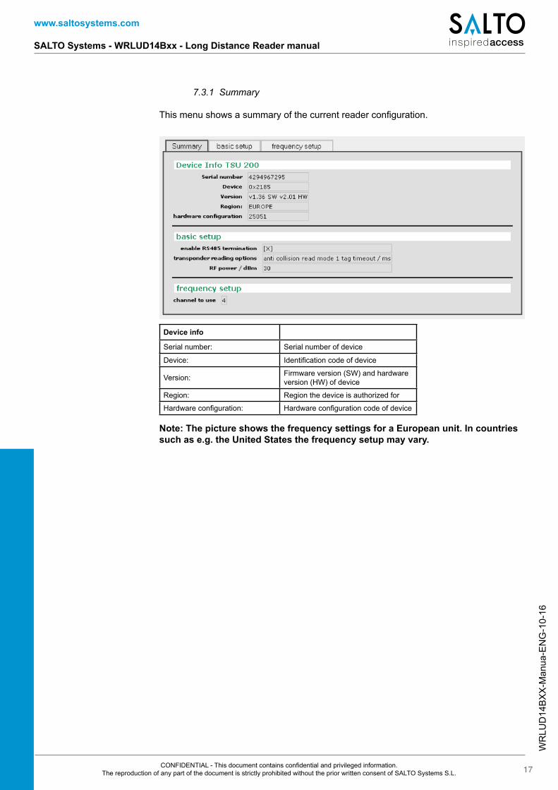
Device info
Serial number: Serial number of device
Device: Identification code of device
Version: Firmware version (SW) and hardware version (HW) of device
Region: Region the device is authorized for
Hardware configuration: Hardware configuration code of device
7.3.1 Summary
This menu shows a summary of the current reader configuration.
Note: The picture shows the frequency settings for a European unit. In countries such as e.g. the United States the frequency setup may vary.
WR
LUD
14B
XX
-Man
ua-E
NG
-10-
16
www.saltosystems.com
SALTO Systems - WRLUD14Bxx - Long Distance Reader manual
18CONFIDENTIAL - This document contains confidential and privileged information. The reproduction of any part of the document is strictly prohibited without the prior written consent of SALTO Systems S.L.
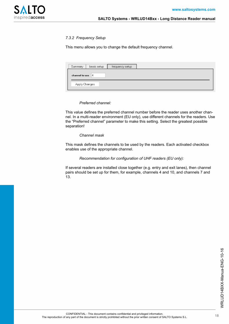
7.3.2 Frequency Setup
This menu allows you to change the default frequency channel.
Preferred channel:
This value defines the preferred channel number before the reader uses another chan-nel. In a multi-reader environment (EU only), use different channels for the readers. Use the “Preferred channel” parameter to make this setting. Select the greatest possible separation!
Channel mask
This mask defines the channels to be used by the readers. Each activated checkbox enables use of the appropriate channel.
Recommendation for configuration of UHF readers (EU only):
If several readers are installed close together (e.g. entry and exit lanes), then channel pairs should be set up for them, for example, channels 4 and 10, and channels 7 and 13.
WR
LUD
14B
XX
-Man
ua-E
NG
-10-
16
www.saltosystems.com
SALTO Systems - WRLUD14Bxx - Long Distance Reader manual
19CONFIDENTIAL - This document contains confidential and privileged information. The reproduction of any part of the document is strictly prohibited without the prior written consent of SALTO Systems S.L.
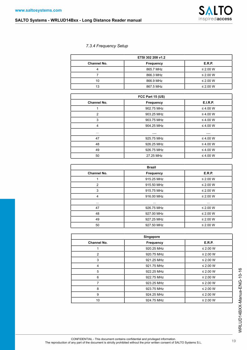
7.3.4 Frequency Setup
ETSI 302 208 v1.2
Channel No. Frequency E.R.P.
4 865.7 MHz ≤ 2.00 W
7 866.3 MHz ≤ 2.00 W
10 866.9 MHz ≤ 2.00 W
13 867.5 MHz ≤ 2.00 W
Singapore
Channel No. Frequency E.R.P.
1 920.25 MHz ≤ 2.00 W
2 920.75 MHz ≤ 2.00 W
3 921.25 MHz ≤ 2.00 W
4 921.75 MHz ≤ 2.00 W
5 922.25 MHz ≤ 2.00 W
6 922.75 MHz ≤ 2.00 W
7 923.25 MHz ≤ 2.00 W
8 923.75 MHz ≤ 2.00 W
9 924.25 MHz ≤ 2.00 W
10 924.75 MHz ≤ 2.00 W
Brazil
Channel No. Frequency E.R.P.
1 915.25 MHz ≤ 2.00 W
2 915.50 MHz ≤ 2.00 W
3 915.75 MHz ≤ 2.00 W
4 916.00 MHz ≤ 2.00 W
... ... ...
47 926.75 MHz ≤ 2.00 W
48 927.00 MHz ≤ 2.00 W
49 927.25 MHz ≤ 2.00 W
50 927.50 MHz ≤ 2.00 W
FCC Part 15 (US)
Channel No. Frequency E.I.R.P.
1 902.75 MHz ≤ 4.00 W
2 903.25 MHz ≤ 4.00 W
3 903.75 MHz ≤ 4.00 W
4 904.25 MHz ≤ 4.00 W
... ... ...47 925.75 MHz ≤ 4.00 W
48 926.25 MHz ≤ 4.00 W
49 926.75 MHz ≤ 4.00 W
50 27.25 MHz ≤ 4.00 W
WR
LUD
14B
XX
-Man
ua-E
NG
-10-
16
www.saltosystems.com
SALTO Systems - WRLUD14Bxx - Long Distance Reader manual
20CONFIDENTIAL - This document contains confidential and privileged information. The reproduction of any part of the document is strictly prohibited without the prior written consent of SALTO Systems S.L.
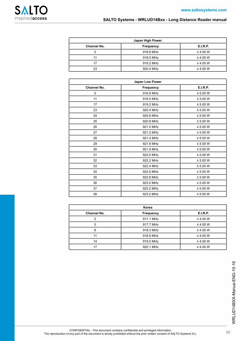
Japan High Power
Channel No. Frequency E.I.R.P.
5 916.8 MHz ≤ 4.00 W
11 918.0 MHz ≤ 4.00 W
17 919.2 MHz ≤ 4.00 W
23 920.4 MHz ≤ 4.00 W
Korea
Channel No. Frequency E.I.R.P.
2 917.1 MHz ≤ 4.00 W
5 917.7 MHz ≤ 4.00 W
8 918.3 MHz ≤ 4.00 W
11 918.9 MHz ≤ 4.00 W
14 919.5 MHz ≤ 4.00 W
17 920.1 MHz ≤ 4.00 W
Japan Low Power
Channel No. Frequency E.I.R.P.
5 916.8 MHz ≤ 5.00 W
11 918.0 MHz ≤ 5.00 W
17 919.2 MHz ≤ 5.00 W
23 920.4 MHz ≤ 5.00 W
24 920.6 MHz ≤ 5.00 W
25 920.8 MHz ≤ 5.00 W
26 921.0 MHz ≤ 5.00 W
27 921.2 MHz ≤ 5.00 W
28 921.4 MHz ≤ 5.00 W
29 921.6 MHz ≤ 5.00 W
30 921.8 MHz ≤ 5.00 W
31 922.0 MHz ≤ 5.00 W
32 922.2 MHz ≤ 5.00 W
33 922.4 MHz ≤ 5.00 W
34 922.6 MHz ≤ 5.00 W
35 922.8 MHz ≤ 5.00 W
36 923.0 MHz ≤ 5.00 W
37 923.2 MHz ≤ 5.00 W
38 923.2 MHz ≤ 5.00 W
WR
LUD
14B
XX
-Man
ua-E
NG
-10-
16
www.saltosystems.com
SALTO Systems - WRLUD14Bxx - Long Distance Reader manual
21CONFIDENTIAL - This document contains confidential and privileged information. The reproduction of any part of the document is strictly prohibited without the prior written consent of SALTO Systems S.L.
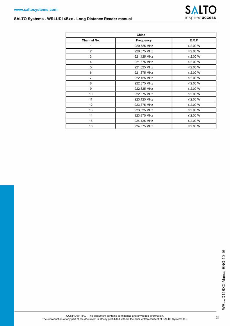
China
Channel No. Frequency E.R.P.
1 920.625 MHz ≤ 2.00 W
2 920.875 MHz ≤ 2.00 W
3 921.125 MHz ≤ 2.00 W
4 921.375 MHz ≤ 2.00 W
5 921.625 MHz ≤ 2.00 W
6 921.875 MHz ≤ 2.00 W
7 922.125 MHz ≤ 2.00 W
8 922.375 MHz ≤ 2.00 W
9 922.625 MHz ≤ 2.00 W
10 922.875 MHz ≤ 2.00 W
11 923.125 MHz ≤ 2.00 W
12 923.375 MHz ≤ 2.00 W
13 923.625 MHz ≤ 2.00 W
14 923.875 MHz ≤ 2.00 W
15 924.125 MHz ≤ 2.00 W
16 924.375 MHz ≤ 2.00 W
WR
LUD
14B
XX
-Man
ua-E
NG
-10-
16
www.saltosystems.com
SALTO Systems - WRLUD14Bxx - Long Distance Reader manual
22CONFIDENTIAL - This document contains confidential and privileged information. The reproduction of any part of the document is strictly prohibited without the prior written consent of SALTO Systems S.L.
Notes:
WR
LUD
14B
XX
-Man
ua-E
NG
-10-
16
www.saltosystems.com
SALTO Systems - WRLUD14Bxx - Long Distance Reader manual
23CONFIDENTIAL - This document contains confidential and privileged information. The reproduction of any part of the document is strictly prohibited without the prior written consent of SALTO Systems S.L.
Notes:
—
Copyright © 2016 SALTO Systems
SALTO Systems reserves the right to modify technical specifications, designs and performance without notice. The paper used is FSC certified.
SALTO Systems HQ, Spain Oiartzun, Spain
Tel.: +34 943 344 550email: [email protected] SALTO Systems, UK Southam, United Kingdom
Tel.: +44 01926 811979email: [email protected] SALTO Systems, USA Norcross GA, USA
Tel.: +1 770 452 6091email: [email protected] SALTO Systems, Canada Vaudreil-Dorion QC, Canada
Tel.: +1 514 616 2586 email: [email protected] www.saltohospitality.com SALTO Systems, Mexico Cancún, México
Tel.: +52 (998) 892 8752 email: [email protected] www.saltohospitality.com SALTO Systems, Colombia Bogota, Colombia
Tel.: +57 1 810 7013 email: [email protected] www.saltohospitality.com SALTO Systems, Australia Waterloo - Sydney, Australia
Tel.: +61 1 3007 39959 email: [email protected] www.saltohospitality.com SALTO Systems, Australia Melbourne, Australia
Tel.: +61 1 3007 39959 email: [email protected] www.saltohospitality.com SALTO Systems, Middle East Dubai, United Arab Emirates
Tel.: +971 48 811 050 email: [email protected] www.saltohospitality.com
SALTO Systems, France Nanterre, France
Tel: +33 (0)1 55 17 13 70 email: [email protected] www.saltohospitality.com SALTO Systems, Germany Wuppertal, Deutschland
Tel.: +49 (0)202/ 769 579-0 email: [email protected] www.saltohospitality.com SALTO Systems, Switzerland Eschlikon, Switzerland
Tel: +41 71 973 72 72 email: [email protected] www.saltohospitality.com SALTO Systems, Netherlands Amsterdam, The Netherlands
Tel: +31 206 353 100email: [email protected] www.saltohospitality.com SALTO Systems, Belgium Brussels, Belgium
Tel: +31 206 353 100 email: [email protected] www.saltohospitality.com SALTO Systems, Poland Warszawa, Polska
Tel: +48 609 01 7777 email: [email protected] www.saltohospitality.com SALTO Systems, Slovakia Bratislava, Slovakia
Tel: +48 609 01 7777 email: [email protected] www.saltohospitality.com SALTO Systems, Czech Republic Prague, Czech Republic
Tel: +48 609 01 7777 email: [email protected] www.saltohospitality.com SALTO Systems, Denmark Kalundborg, Denmark
Tel.: +45 48 44 88 11 email: [email protected]
SALTO Systems, Norway Jessheim, Norway
Tel.: +47 46 747 884email: [email protected] SALTO Systems, Sweden Stockholm - Malmö, Sweden
Tel.: +46 (0)8-555 982 00email: [email protected] SALTO Systems, Finland Vantaa, Finland
Tel: +35 892 316 5639 email: [email protected] www.saltohospitality.com SALTO Systems, Italy Bologna, Italy
Tel: +39 342 55 67 739 email: [email protected] www.saltohospitality.com SALTO Systems, Portugal Lisboa - Porto, Portugal
Tel.: +351 220 937 508 email: [email protected] www.saltohospitality.com SALTO Systems, Singapore Singapore
Tel: +65 6557 22 55 email: [email protected] SALTO Systems, China Shanghai, China
Tel: +86 (8621) 3157 6115 email: [email protected] www.saltohospitality.com SALTO Systems, Hong Kong Hong Kong
Tel: +65 6557 22 55 email: [email protected] www.saltohospitality.com SALTO Systems, South Africa Johannesburgo, South Africa
Tel: +27 (83) 293 07 96 email: [email protected] www.saltohospitality.com