salto talaris instrumentation ii - london … · 2 introduction ™ salto talaris instrumentation...
TRANSCRIPT

Salto Talaris™
Total Ankle Prosthesis
SALTO TALARISINSTRUMENTATION II
SALTO TALARISINSTRUMENTATION II
TABLE OF CONTENTSINTRODUCTION
1. Design rationale
2. Specific indications for ankle replacement surgery
3. Instrumentation concept
4. Preoperative planning
5. Compatibility rules when choosing implant size
SURGICAL TECHNIQUE 1. Surgical approach
2. Exostectomy of the distal tibia
3. Positioning the tibial alignment guide
4. Adjusting the alignment guide
5. Final adjustment of cutting height, rotation, and lateral position
6. Preselection of talar implant size
7. Placing the cutting guide
8. Preparation for drilling lateral sides of tibia
9. Tibial cut
10. Preparing the posterior talar cut
11. Setting the talar resection guide and the talar pins
12. Talar resection on pins
13. Anterior talar chamfer
14. Positioning the lateral resection guide
15. Drilling the talar plug
16. Precautions when using a size 0 for a lateral resection
17. Placing the trial talar implant
18. Dynamic test and drilling of tibial plug
19. Finishing touches on the tibial keel
20. Placing final implants
21. Rehabilitation protocol
22. Revising or removing implants
INSTRUMENTS
SINGLE USE ITEMS
IMPLANTS
Salto
Tal
aris
™IN
STRU
MEN
TATI
ON
II p. 1-5
p. 6-28
p. 29-31p. 32p. 33
Surgical Technique Salto Talaris™ UJAT092
TABLE OF CONTENTS
SALTO FIXE US_UJAT092:SALTO US 29/06/09 11:30 Page 2
INTRODUCTION
1
The Salto Talaris™ Total Ankle Prosthesis is a precision fixed-bearing design founded on theSalto mobile-bearing ankle prosthesis, which has been in use since 1997 and at 6.4 year meanfollow-up (5-8.5) has a 93% survivorship. 1
Improvement in the precision of the instrumentation to achieve accurate and reproducibletibiotalar alignment enables the simplification of the implant system to a fixed-bearing design.A key principle is that the mobile-bearing concept has been moved from the implant to theinstrumentation at the stage of the trial reduction. First, a measured resection with equalimplant replacement is applied to the talus and distal tibia. Then, the trial tibial base,featuring a highly polished surface that remains mobile against the resected distal tibia, isallowed to rotate into proper position during ankle Range Of Motion (ROM) through a securelyfixed, highly conforming articulating insert. Only after this intrinsic tibiotalar alignment isachieved are the bone cuts for the tibial keel and plug completed, fixing the tibial base andinsert assembly into the optimized position.
The anatomic design of the talar component reproduces normal ankle kinematics without over -stressing the deltoid ligaments. The means of fixation for the tibial base and talar implant hasnot been altered from the Salto mobile-bearing design.
The key design principles of the Salto Total Ankle Prosthesis, that has provided excellentclinical results, were retained in the Salto Talaris™ Total Ankle Prosthesis. The accuracy andreproducibility of the instrumentation has evolved to allow a precision fixed-bearing implantdesign that represents the philosophy “Less is Sometimes More”.
The Salto Talaris Surgical Technique has been reviewed in conjunction with :Mark Casillas, MD (Foot and Ankle Center of South T exas)Brian Donley, MD (Cleveland Clinic Health Systems)Sheldon Lin, MD (New Jersey Medical School)
1. Bonnin M, Judet T, Piriou P, et al. Total ankle prosthesis: five to eight year results. Presented at theAmerican Orthopaedic Foot and Ankle Society 22nd Annual Summer Meeting. July 14-16, 2006. La Jolla, CA.
1. DESIGN RATIONALE
Surgical Technique Salto Talaris™ UJAT092
Salto
Tal
aris
™IN
STRU
MEN
TATI
ON
II
SALTO FIXE US_UJAT092:SALTO US 29/06/09 11:30 Page 1
2
INTRODUCTIONSa
lto T
alar
is™
INST
RUM
ENTA
TIO
N II
2. SPECIFIC INDICATIONS FOR ANKLE REPLACEMENT SURGERY
Surgical Technique Salto Talaris™ UJAT092
INDICATIONSThe Salto Talaris™ Total Ankle Prosthesis is indicated as a total ankle replacement in primary orrevision surgery for patients with ankle joints damaged by severe rheumatoid, post-traumatic, ordegenerative arthritis. All components are intended for cemented use only .
CONTRAINDICATIONSThe Salto Talaris™ Total Ankle Prosthesis is contraindicated for the following conditions: Sepsis,infection sequelae, systemic infection, elevated WBC count, fever and/or local inflammation,Complete talar necrosis or insufficient quality of bone stock, Persisting skin lesion or poor skincoverage around the ankle joint that would make the procedure unjustifiable, Important ligamentlaxity, Severe osteoporosis, Ankle arthrodesis with malleolar exeresis, Neuromuscular or mentaldisorders which might jeopardize fixation and post-operative care, Neurobiologic diseases,Nonfunctional lower limb muscle, Complete loss of ankle collateral ligament, Charcot’ s arthropathy,Distant foci of infection from genitourinary, pulmonary, skin and other sites; dental focus infectionwhich may cause hematogenous spread to the implant site, Bone immaturity , Known allergy to one ofthe materials, Pregnancy.
WARNINGS AND PRECAUTIONS The following conditions tend to adversely affect ankle replacement implants: Obesity or excessive patient weight, Manual labor, Active sports participation and/or high activitylevel, Likelihood of falls, Alcohol and/or drug addiction, Other disabilities, as appropriate,Poor bone stock, Metabolic disorders or systemic pharmacological treatments leading toprogressive deterioration of solid bone support for the implant (e.g. diabetes, steroid usage,immunosuppressive treatments), Compromise of the ligaments or other supporting soft tissuestructures such that they cannot withstand expected loads following arthroplasty , due to, forexample, rheumatoid arthritis or other diseases affecting the quality of the soft tissue,Severe deformities of the joint, Tumors of the supporting bone structures, Sensitivity , allergy or otherreactions to implant materials (i.e. polyethylene, bone cement or metal), Elevated sedimentation rateunexplained by rheumatoid arthritis.
ADVERSE EVENTS The following are the most frequent adverse events after ankle arthroplasty: Dislocation, Infection,Poor wound healing, Loosening of components, Instability , Bone fracture, Secondary necrosis of thetalus, Neuropathies, Disassembly or breakage of components, Possible metal sensitivity , Otherdiseases affecting the quality of the soft tissue, Severe deformities of the joint, T umors of thesupporting bone structures, Sensitivity, Allergy or Other reactions to implant materials, (i.e.polyethylene, bone cement or metal).
SALTO FIXE US_UJAT092:SALTO US 29/06/09 11:30 Page 2
INTRODUCTION
3
3. INSTRUMENTATION CONCEPT
Surgical Technique Salto Talaris™ UJAT092
Salto
Tal
aris
™IN
STRU
MEN
TATI
ON
IIThe instrumentation is designed to achieve accurate and reproducible tibiotalar alignment while adapting to variousanatomical conditions, depending on the lesions encountered in the ankle or a particular morphotype. The broad steps of this operative technique can be summarized as follows.
1. Patient positioning
The patient is placed in a supine position with a bump under ipsilateral hip to reduce external rotation of theextremity. The heel is placed near the end of the table. A bump under the calf should be used throughout the surgeryto keep the heel off the table.
2. Initial tibial preparation
The tibial cutting line is first determined using a resection guide to align the cut on the tibia and take into accountthe geometry and orientation of the tibiotalar joint.
3. Talar preparation
The talar cuts are then refined to approach the resurfacing step in relation to the initial tibial cut.
4. Final adjustments in the tibial implant position
The mobile-bearing concept has been moved from the implant to the instrumentation at the stage of the trialreduction.The trial tibial base, featuring a highly polished surface that remains mobile against the resected distal tibia, isallowed to rotate into the proper position, thus self-aligning the prosthesis. After this optimal tibiotalar alignment isachieved, the preparation for the tibial keel and plug are completed. The Salto Talaris™ instrumentation ensures proper positioning of the tibial implant in relation to the talar implant fora successful arthroplasty.
SALTO FIXE US_UJAT092:SALTO US 29/06/09 11:30 Page 3
INTRODUCTION
4
Salto
Tal
aris
™IN
STRU
MEN
TATI
ON
II
Surgical Technique Salto Talaris™ UJAT092
4. PREOPERATIVE PLANNING
The preoperative planning for the Salto Talaris™ Total Ankle Prosthesis is carried out using three standardweightbearing radiological views:Anterior view;Anterior view with 30° internal rotation to expose the tibial-fibular joint space;Straight lateral.
Examination of the healthy side should be used for comparison.
Complementary imaging may be requested to:• Confirm or reject the indication (CT scan examination for talar necrosis, a relative contraindication forprosthetic replacement);• Discuss the need for an associated procedure (i.e. presence of subtalar osteoarthritis);
Special consideration should be given to two types of pre-existing conditions.• Malunions responsible for malalignment of the tibia or imbalance of the malleoli, which may require an initialcorrection. • Major ligamentous instabilities demonstrated by an examination under stress will require specific intervention(release of the retracted side or possible need for an associated ligamentoplasty on the lengthened side).
1. Key planning elements determined from the anterior view:
• Choice of an implant size that does not impinge with the lateral malleolus;• Determination of the ideal joint line level accommodating for articular wear . Comparative images are oftennecessary to assess the prosthetic joint space, which should be located at the theoretical anatomic joint space.The thickness of the tibial resection depends on this determination.
2. Key planning elements determined from the lateral view:
• Confirmation of the implant size selected from the anterior view;• Evaluation of the anterior osteophytic margin and assessment of the proposed bone resection required toexpose the roof of the pilon;• Evaluation of talar dome morphology, particularly its degree of convexity;• Evaluation of talar positioning, which can be centered or retroplaced beneath the pilon. The relativepositioning of the tibial and talar components should take into account a possible off-centered location with theunderstanding that the prosthesis adapts to this position and does not correct it. In extreme cases, a pronouncedanterior or posterior talar subluxation may preclude implantation of a prosthesis.
3. Complementary imaging may be required:
To determine the need for an associated procedure:• CT scan to evaluate adequacy of bone stock and the possible presence of contiguous joint arthritis.• MRI to evaluate the extent of avascular necrosis (A VN).
Special consideration should be given to two types of situations:• Malunions that produce malalignment of the ankle.• Ligamentous instabilities.
SALTO FIXE US_UJAT092:SALTO US 29/06/09 11:30 Page 4

INTRODUCTION
5
5. COMPATIBILITY RULES WHEN CHOOSING IMPLANT SIZE
Surgical Technique Salto Talaris™ UJAT092
Salto
Tal
aris
™IN
STRU
MEN
TATI
ON
II1. General rules
- The Tibial component size is always the same or one size bigger than the T alar component size.
- The polyethylene insert (PE) matches the Talar component size except for the size 0 Talar component which hasto be associated with the size 0 T ibial insert or size 00 Tibial insert.
2. Additional information
- The tibial implant comes in 4 symmetrical sizes that can all be implanted on either the right or the left ankle.
- The PE insert is clipped onto the tibial base to form a single-block component. The insert thicknesses arenamed for the tibial base thickness. The inserts therefore come in 4 thicknesses, from 8 to 11 mm (includesthickness of the metallic tibial base + thickness of PE). Unlike the tibial implant, the PE inserts are specific foreach side, right and left.
- When the patient’s anatomy requires using a size 0 tibial implant, a size 00 insert must be associated with it(available for each side, right and left), whose width and clipping system are compatible with the size 0 tibialimplant, and whose curvature corresponds to that of the size 0 talar implant.
- However, when the patient’s anatomy presents a tibia requiring size 1, but requires use of a size 0 talarcomponent, the intermediary insert must be size 0, whose width and clipping system are compatible with thesize 1 tibial implant, and whose curvature corresponds to that of the size 0 talar implant.
COMPATIBILITY CHART FOR SALTO TALARIS™ TOTAL ANKLE PROSTHESIS
Tibialpart
Insert
Talarpart
0 1 2 3
00 0 1 2 3
0 1 2 3
SALTO FIXE US_UJAT092:SALTO US 29/06/09 11:30 Page 5
SURGICAL TECHNIQUE
(fig. 01)Anterior approach
(fig. 02)
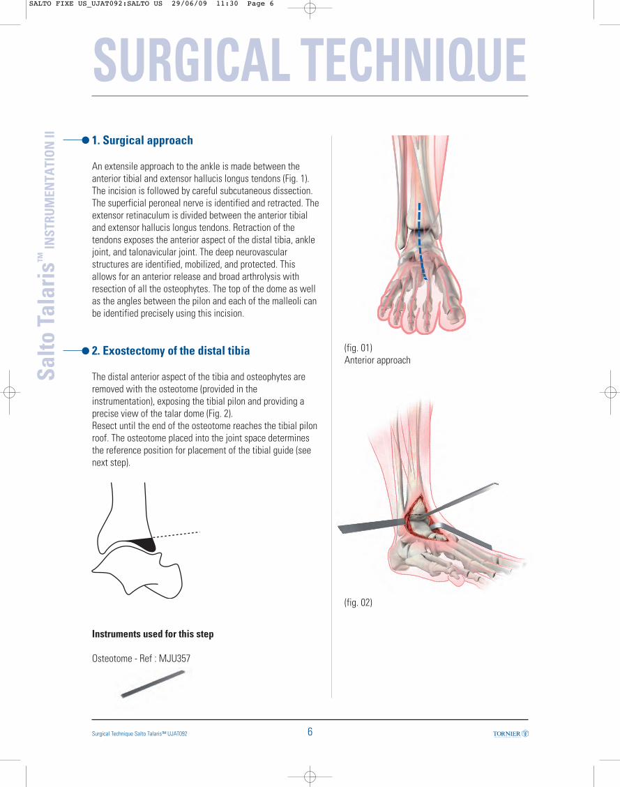
1. Surgical approach
An extensile approach to the ankle is made between theanterior tibial and extensor hallucis longus tendons (Fig. 1).The incision is followed by careful subcutaneous dissection.The superficial peroneal nerve is identified and retracted. Theextensor retinaculum is divided between the anterior tibialand extensor hallucis longus tendons. Retraction of thetendons exposes the anterior aspect of the distal tibia, anklejoint, and talonavicular joint. The deep neurovascularstructures are identified, mobilized, and protected. Thisallows for an anterior release and broad arthrolysis withresection of all the osteophytes. The top of the dome as wellas the angles between the pilon and each of the malleoli canbe identified precisely using this incision.
2. Exostectomy of the distal tibia
The distal anterior aspect of the tibia and osteophytes areremoved with the osteotome (provided in theinstrumentation), exposing the tibial pilon and providing aprecise view of the talar dome (Fig. 2). Resect until the end of the osteotome reaches the tibial pilonroof. The osteotome placed into the joint space determinesthe reference position for placement of the tibial guide (seenext step).
Instruments used for this step
Osteotome - Ref : MJU357
Salto
Tal
aris
™IN
STRU
MEN
TATI
ON
II
6Surgical Technique Salto Talaris™ UJAT092
SALTO FIXE US_UJAT092:SALTO US 29/06/09 11:30 Page 6
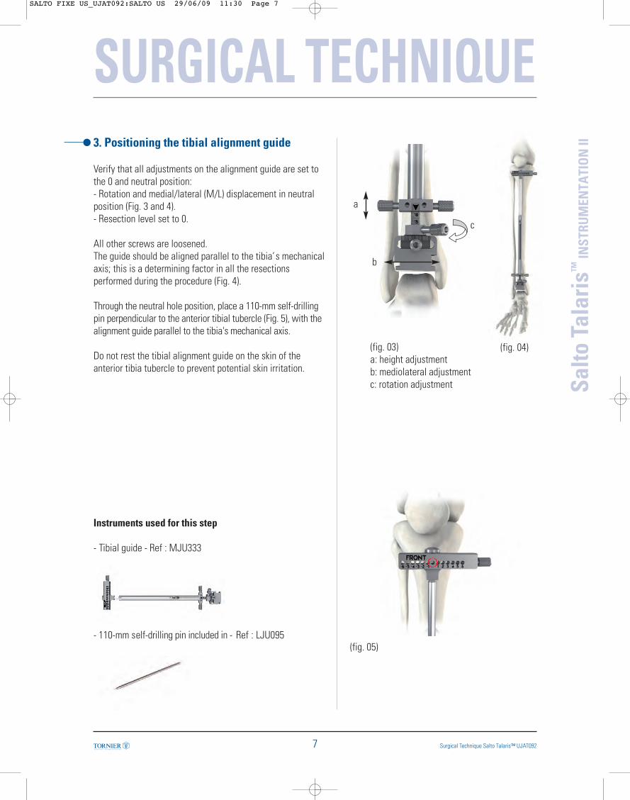
3. Positioning the tibial alignment guide
Verify that all adjustments on the alignment guide are set tothe 0 and neutral position:- Rotation and medial/lateral (M/L) displacement in neutralposition (Fig. 3 and 4).- Resection level set to 0.
All other screws are loosened.The guide should be aligned parallel to the tibia’s mechanicalaxis; this is a determining factor in all the resectionsperformed during the procedure (Fig. 4).
Through the neutral hole position, place a 110-mm self-drillingpin perpendicular to the anterior tibial tubercle (Fig. 5), with thealignment guide parallel to the tibia's mechanical axis.
Do not rest the tibial alignment guide on the skin of theanterior tibia tubercle to prevent potential skin irritation.
Instruments used for this step
- Tibial guide - Ref : MJU333
- 110-mm self-drilling pin included in - Ref : LJU095
(fig. 04)
(fig. 05)
a
b
c
SURGICAL TECHNIQUE
7 Surgical Technique Salto Talaris™ UJAT092
Salto
Tal
aris
™IN
STRU
MEN
TATI
ON
II
(fig. 03)a: height adjustmentb: mediolateral adjustmentc: rotation adjustment
SALTO FIXE US_UJAT092:SALTO US 29/06/09 11:30 Page 7
SURGICAL TECHNIQUE
8Surgical Technique Salto Talaris™ UJAT092
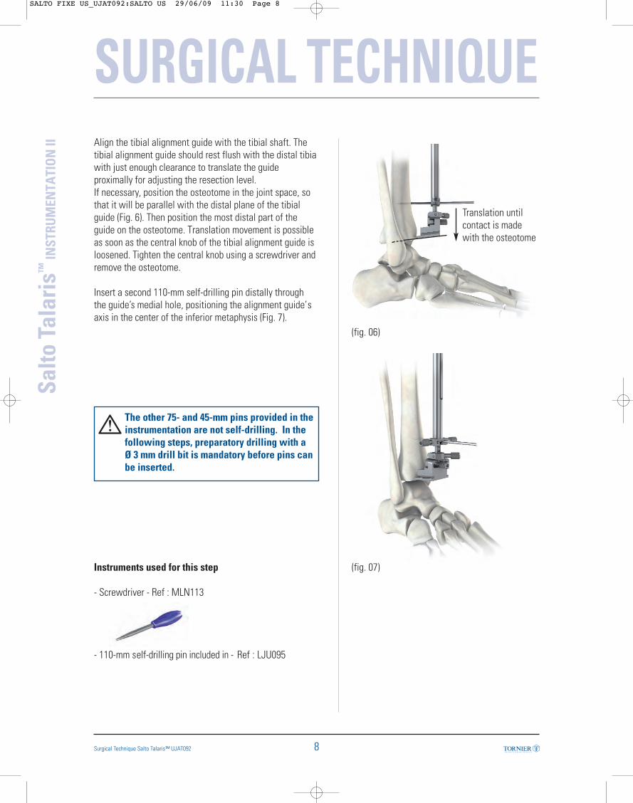
(fig. 06)
(fig. 07)
Translation untilcontact is madewith the osteotome
Align the tibial alignment guide with the tibial shaft. Thetibial alignment guide should rest flush with the distal tibiawith just enough clearance to translate the guideproximally for adjusting the resection level.If necessary, position the osteotome in the joint space, sothat it will be parallel with the distal plane of the tibialguide (Fig. 6). Then position the most distal part of theguide on the osteotome. Translation movement is possibleas soon as the central knob of the tibial alignment guide isloosened. Tighten the central knob using a screwdriver andremove the osteotome.
Insert a second 110-mm self-drilling pin distally throughthe guide’s medial hole, positioning the alignment guide’saxis in the center of the inferior metaphysis (Fig. 7).
The other 75- and 45-mm pins provided in theinstrumentation are not self-drilling. In thefollowing steps, preparatory drilling with aØ 3 mm drill bit is mandatory before pins canbe inserted.
Instruments used for this step
- Screwdriver - Ref : MLN113
- 110-mm self-drilling pin included in - Ref : LJU095
Salto
Tal
aris
™IN
STRU
MEN
TATI
ON
II
SALTO FIXE US_UJAT092:SALTO US 29/06/09 11:30 Page 8
SURGICAL TECHNIQUE
9 Surgical Technique Salto Talaris™ UJAT092
Salto
Tal
aris
™IN
STRU
MEN
TATI
ON
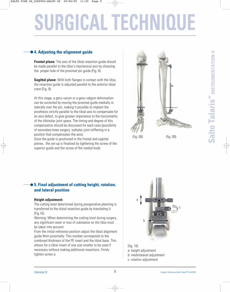
II4. Adjusting the alignment guide
Frontal plane: The axis of the tibial resection guide shouldbe made parallel to the tibia’s mechanical axis by choosingthe proper hole of the proximal pin guide (Fig. 8).
Sagittal plane: With both flanges in contact with the tibia,the resection guide is adjusted parallel to the anterior tibialcrest (Fig. 9).
At this stage, a genu varum or a genu valgum deformationcan be corrected by moving the proximal guide medially orlaterally over the pin, making it possible to implant theprosthesis strictly parallel to the tibial axis to compensate foran axis defect, to give greater importance to the horizontalityof the tibiotalar joint space. The timing and degree of thiscompensation should be discussed for each case (possibilityof secondary knee surgery, subtalar joint stiffening in aposition that compensates the axis).Once the guide is positioned in the frontal and sagittalplanes, the set-up is finalized by tightening the screw of thesuperior guide and the screw of the medial knob.
5. Final adjustment of cutting height, rotation,and lateral position
Height adjustment:The cutting level determined during preoperative planning istransferred to the distal resection guide by translating it(Fig.10). Warning: When determining the cutting level during surgery ,any significant wear or loss of substance on the tibia mustbe taken into account. From the initial reference position adjust the tibial alignmentguide 9mm proximally. This number corresponds to thecombined thickness of the PE insert and the tibial base. Thisallows for a tibial insert of one size smaller to be used ifnecessary without making additional resections. Firmlytighten screw a.
(fig. 10)a: height adjustmentb: mediolateral adjustmentc: rotation adjustment
(fig. 08) (fig. 09)
a
b
c
SALTO FIXE US_UJAT092:SALTO US 29/06/09 11:30 Page 9
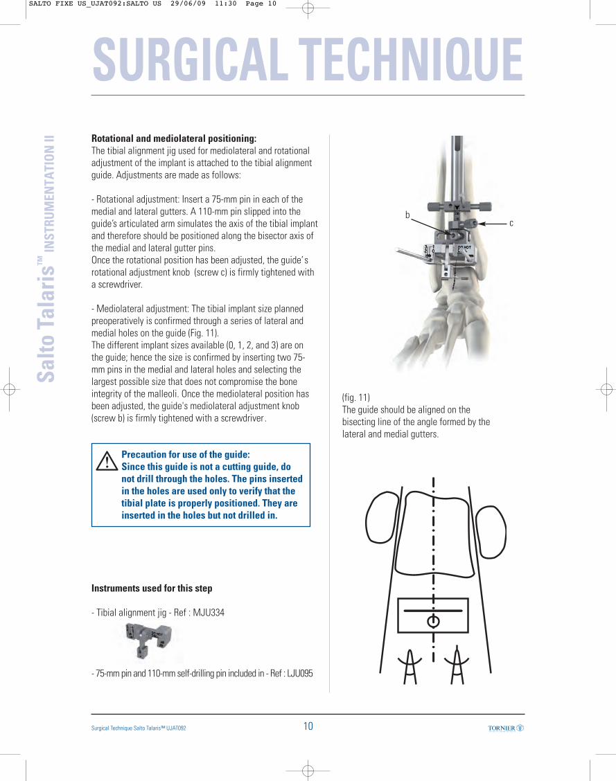
Rotational and mediolateral positioning:The tibial alignment jig used for mediolateral and rotationaladjustment of the implant is attached to the tibial alignmentguide. Adjustments are made as follows:
- Rotational adjustment: Insert a 75-mm pin in each of themedial and lateral gutters. A 110-mm pin slipped into theguide’s articulated arm simulates the axis of the tibial implantand therefore should be positioned along the bisector axis ofthe medial and lateral gutter pins. Once the rotational position has been adjusted, the guide’srotational adjustment knob (screw c) is firmly tightened witha screwdriver.
- Mediolateral adjustment: The tibial implant size plannedpreoperatively is confirmed through a series of lateral andmedial holes on the guide (Fig. 11).The different implant sizes available (0, 1, 2, and 3) are onthe guide; hence the size is confirmed by inserting two 75-mm pins in the medial and lateral holes and selecting thelargest possible size that does not compromise the boneintegrity of the malleoli. Once the mediolateral position hasbeen adjusted, the guide's mediolateral adjustment knob(screw b) is firmly tightened with a screwdriver .
Precaution for use of the guide:Since this guide is not a cutting guide, donot drill through the holes. The pins insertedin the holes are used only to verify that thetibial plate is properly positioned. They areinserted in the holes but not drilled in.
Instruments used for this step
- Tibial alignment jig - Ref : MJU334
- 75-mm pin and 110-mm self-drilling pin included in - Ref : LJU095
SURGICAL TECHNIQUE
10
Salto
Tal
aris
™IN
STRU
MEN
TATI
ON
II
Surgical Technique Salto Talaris™ UJAT092
(fig. 11)The guide should be aligned on thebisecting line of the angle formed by thelateral and medial gutters.
cb
SALTO FIXE US_UJAT092:SALTO US 29/06/09 11:30 Page 10
SURGICAL TECHNIQUE
11 Surgical Technique Salto Talaris™ UJAT092
Salto
Tal
aris
™IN
STRU
MEN
TATI
ON
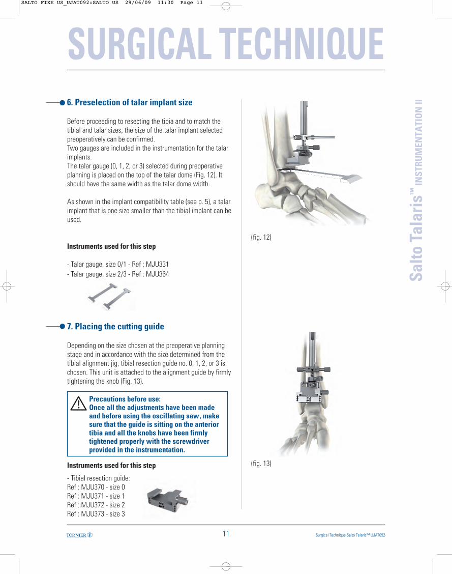
II6. Preselection of talar implant size
Before proceeding to resecting the tibia and to match thetibial and talar sizes, the size of the talar implant selectedpreoperatively can be confirmed.Two gauges are included in the instrumentation for the talarimplants.The talar gauge (0, 1, 2, or 3) selected during preoperativeplanning is placed on the top of the talar dome (Fig. 12). Itshould have the same width as the talar dome width.
As shown in the implant compatibility table (see p. 5), a talarimplant that is one size smaller than the tibial implant can beused.
Instruments used for this step
- Talar gauge, size 0/1 - Ref : MJU331- Talar gauge, size 2/3 - Ref : MJU364
7. Placing the cutting guide
Depending on the size chosen at the preoperative planningstage and in accordance with the size determined from thetibial alignment jig, tibial resection guide no. 0, 1, 2, or 3 ischosen. This unit is attached to the alignment guide by firmlytightening the knob (Fig. 13).
Precautions before use: Once all the adjustments have been madeand before using the oscillating saw, makesure that the guide is sitting on the anteriortibia and all the knobs have been firmlytightened properly with the screwdriverprovided in the instrumentation.
Instruments used for this step
- Tibial resection guide:Ref : MJU370 - size 0Ref : MJU371 - size 1Ref : MJU372 - size 2Ref : MJU373 - size 3
(fig. 12)
(fig. 13)
SALTO FIXE US_UJAT092:SALTO US 29/06/09 11:30 Page 11
SURGICAL TECHNIQUE
12
Salto
Tal
aris
™IN
STRU
MEN
TATI
ON
II
Surgical Technique Salto Talaris™ UJAT092
(fig. 14)
(fig. 15)
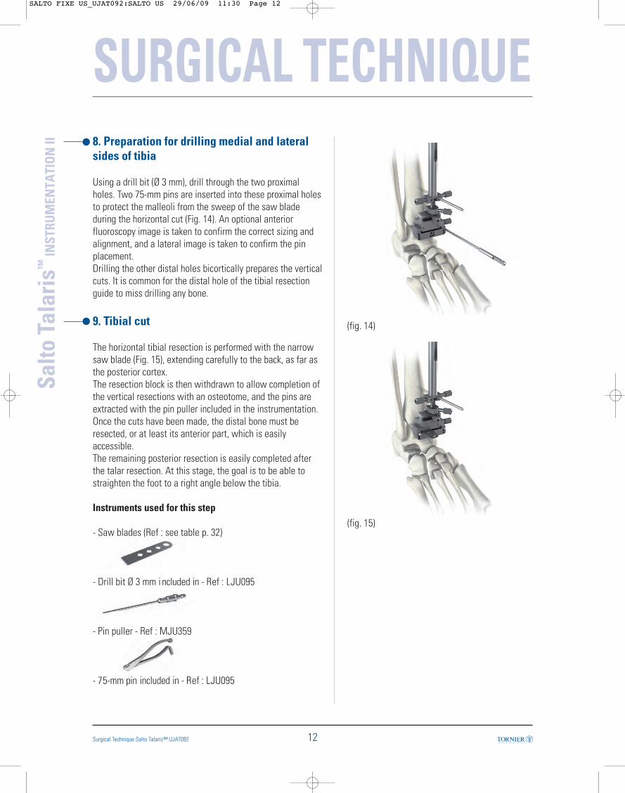
8. Preparation for drilling medial and lateralsides of tibia
Using a drill bit (Ø 3 mm), drill through the two proximalholes. Two 75-mm pins are inserted into these proximal holesto protect the malleoli from the sweep of the saw bladeduring the horizontal cut (Fig. 14). An optional anteriorfluoroscopy image is taken to confirm the correct sizing andalignment, and a lateral image is taken to confirm the pinplacement.Drilling the other distal holes bicortically prepares the verticalcuts. It is common for the distal hole of the tibial resectionguide to miss drilling any bone.
9. Tibial cut
The horizontal tibial resection is performed with the narrowsaw blade (Fig. 15), extending carefully to the back, as far asthe posterior cortex.The resection block is then withdrawn to allow completion ofthe vertical resections with an osteotome, and the pins areextracted with the pin puller included in the instrumentation.Once the cuts have been made, the distal bone must beresected, or at least its anterior part, which is easilyaccessible.The remaining posterior resection is easily completed afterthe talar resection. At this stage, the goal is to be able tostraighten the foot to a right angle below the tibia.
Instruments used for this step
- Saw blades (Ref : see table p. 32)
- Drill bit Ø 3 mm i ncluded in - Ref : LJU095
- Pin puller - Ref : MJU359
- 75-mm pin included in - Ref : LJU095
SALTO FIXE US_UJAT092:SALTO US 29/06/09 11:30 Page 12
SURGICAL TECHNIQUE
13 Surgical Technique Salto Talaris™ UJAT092
Salto
Tal
aris
™IN
STRU
MEN
TATI
ON
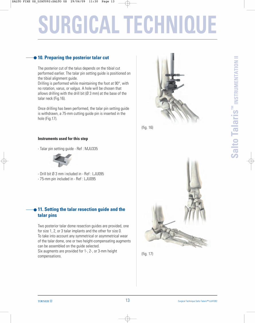
II10. Preparing the posterior talar cut
The posterior cut of the talus depends on the tibial cutperformed earlier. The talar pin setting guide is positioned onthe tibial alignment guide. Drilling is performed while maintaining the foot at 90°, withno rotation, varus, or valgus. A hole will be chosen thatallows drilling with the drill bit (Ø 3 mm) at the base of thetalar neck (Fig.16).
Once drilling has been performed, the talar pin setting guideis withdrawn, a 75-mm cutting guide pin is inserted in thehole (Fig.17).
Instruments used for this step
- Talar pin setting guide - Ref : MJU335
- Drill bit Ø 3 mm i ncluded in - Ref : LJU095- 75-mm pin included in - Ref : LJU095
11. Setting the talar resection guide and thetalar pins
Two posterior talar dome resection guides are provided, onefor size 1, 2, or 3 talar implants and the other for size 0.To take into account any symmetrical or asymmetrical wearof the talar dome, one or two height-compensating augmentscan be assembled on the guide selected. Six augments are provided for 1-, 2-, or 3-mm heightcompensations.
(fig. 16)
(fig. 17)
SALTO FIXE US_UJAT092:SALTO US 29/06/09 11:30 Page 13
SURGICAL TECHNIQUE
14
Salto
Tal
aris
™IN
STRU
MEN
TATI
ON
II
Surgical Technique Salto Talaris™ UJAT092
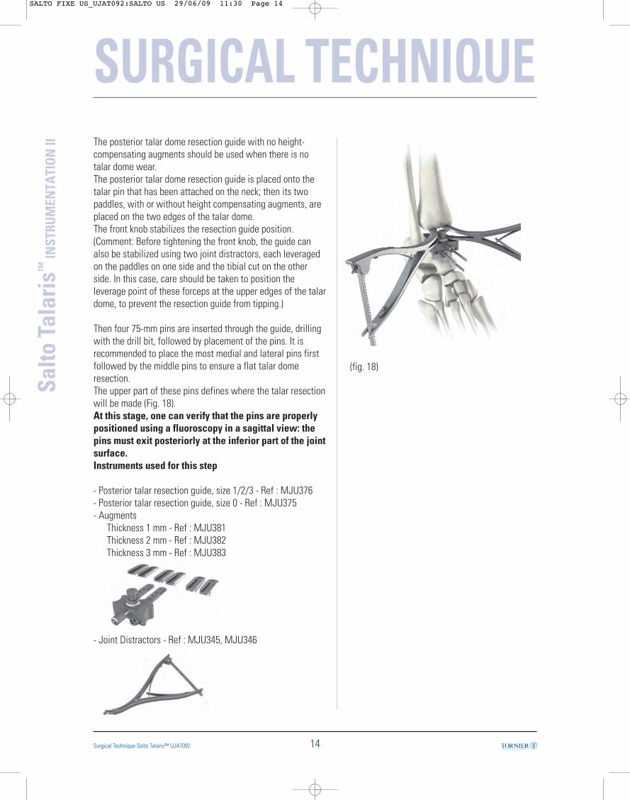
The posterior talar dome resection guide with no height-compensating augments should be used when there is notalar dome wear.The posterior talar dome resection guide is placed onto thetalar pin that has been attached on the neck; then its twopaddles, with or without height compensating augments, areplaced on the two edges of the talar dome. The front knob stabilizes the resection guide position.(Comment: Before tightening the front knob, the guide canalso be stabilized using two joint distractors, each leveragedon the paddles on one side and the tibial cut on the otherside. In this case, care should be taken to position theleverage point of these forceps at the upper edges of the talardome, to prevent the resection guide from tipping.)
Then four 75-mm pins are inserted through the guide, drillingwith the drill bit, followed by placement of the pins. It isrecommended to place the most medial and lateral pins firstfollowed by the middle pins to ensure a flat talar domeresection.The upper part of these pins defines where the talar resectionwill be made (Fig. 18).At this stage, one can verify that the pins are properlypositioned using a fluoroscopy in a sagittal view: thepins must exit posteriorly at the inferior part of the jointsurface. Instruments used for this step
- Posterior talar resection guide, size 1/2/3 - Ref : MJU376- Posterior talar resection guide, size 0 - Ref : MJU375- Augments
Thickness 1 mm - Ref : MJU381Thickness 2 mm - Ref : MJU382Thickness 3 mm - Ref : MJU383
- Joint Distractors - Ref : MJU345, MJU346
(fig. 18)
SALTO FIXE US_UJAT092:SALTO US 29/06/09 11:30 Page 14

SURGICAL TECHNIQUE
15 Surgical Technique Salto Talaris™ UJAT092
Salto
Tal
aris
™IN
STRU
MEN
TATI
ON
II12. Talar resection on pins
With the guide removed, the posterior talar cut is made withthe wide oscillating saw (Fig. 19). To protect the malleoli fromthe sweep of the saw blade, a set of ribbon retractors areprovided in the instrumentation.
To follow the planned resection accurately, the saw shouldcut flush on the surface of the pins.The pins are then removed.
At this stage, after the talar dome is resected, theposterior portion of the distal tibial resection and theposterior arthrolysis can be completed. Any remnant ofbone laterally on the distal tibia should be removedwith rongeurs.
Instruments used for this step
- Ribbon retractors - Ref : MJU086
(fig. 19)
SALTO FIXE US_UJAT092:SALTO US 29/06/09 11:31 Page 15
SURGICAL TECHNIQUE
16
Salto
Tal
aris
™IN
STRU
MEN
TATI
ON
II
Surgical Technique Salto Talaris™ UJAT092
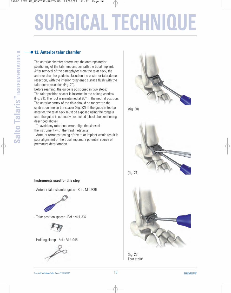
13. Anterior talar chamfer
The anterior chamfer determines the anteroposteriorpositioning of the talar implant beneath the tibial implant.After removal of the osteophytes from the talar neck, theanterior chamfer guide is placed on the posterior talar domeresection, with the inferior roughened surface flush with thetalar dome resection (Fig. 20). Before reaming, the guide is positioned in two steps: The talar position spacer is inserted in the oblong window(Fig. 21). The foot is maintained at 90° in the neutral position.The anterior cortex of the tibia should be tangent to thecalibration line on the spacer (Fig. 22). If the guide is too faranterior, the talar neck must be exposed using the rongeuruntil the guide is optimally positioned (check the positioningdescribed above).- To avoid any rotational error, align the sides ofthe instrument with the third metatarsal. - Ante- or retropositioning of the talar implant would result inpoor alignment of the tibial implant, a potential source ofpremature deterioration.
Instruments used for this step
- Anterior talar chamfer guide - Ref : MJU336
- Talar position spacer - Ref : MJU337
- Holding clamp - Ref : MJU048
(fig. 20)
(fig. 22)Foot at 90°
(fig. 21)
SALTO FIXE US_UJAT092:SALTO US 29/06/09 11:31 Page 16
SURGICAL TECHNIQUE
17 Surgical Technique Salto Talaris™ UJAT092
Salto
Tal
aris
™IN
STRU
MEN
TATI
ON
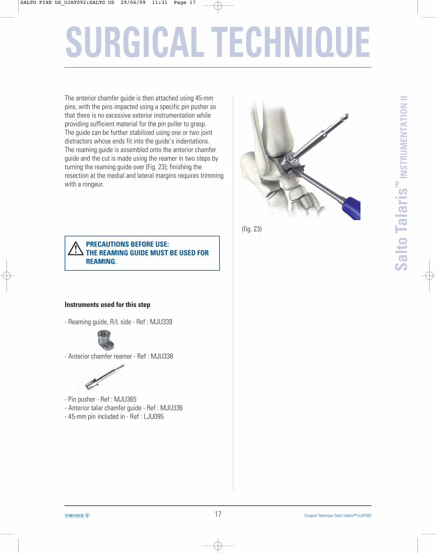
IIThe anterior chamfer guide is then attached using 45-mmpins, with the pins impacted using a specific pin pusher sothat there is no excessive exterior instrumentation whileproviding sufficient material for the pin puller to grasp.The guide can be further stabilized using one or two jointdistractors whose ends fit into the guide’s indentations.The reaming guide is assembled onto the anterior chamferguide and the cut is made using the reamer in two steps byturning the reaming guide over (Fig. 23); finishing theresection at the medial and lateral margins requires trimmingwith a rongeur.
PRECAUTIONS BEFORE USE: THE REAMING GUIDE MUST BE USED FORREAMING.
Instruments used for this step
- Reaming guide, R/L side - Ref : MJU339
- Anterior chamfer reamer - Ref : MJU338
- Pin pusher - Ref : MJU365- Anterior talar chamfer guide - Ref : MJU336- 45-mm pin included in - Ref : LJU095
(fig. 23)
SALTO FIXE US_UJAT092:SALTO US 29/06/09 11:31 Page 17

14. Positioning the lateral resection guide
The lateral chamfer guide is available in two versions: rightand left (as indicated on the instrument). The removablehandle should be screwed onto the guide.The plug-shaped mediolateral positioning gauge is inserted inthe lateral talar resection guide corresponding to the operatedside, with the wing inserted along the guide’s groove. Theguide is set on the anterior and posterior resected surfaces.The guide’s wing is positioned on the resulting apex betweenthe anterior and posterior chamfers. The mediolateral position of the resection guide is determinedby the tip of the wing being aligned on the lateral cortex ofthe talus (Fig. 24).
Instruments used for this step
- Removable handle - Ref : MJU342
- Lateral chamfer guideRight side - Ref : MJU341Left side - Ref : MJU340
- Positioning gauge (plug-shaped) - Ref : MJU343
- 45-mm pin included in - Ref : LJU095
(fig. 24)
SURGICAL TECHNIQUE
18
Salto
Tal
aris
™IN
STRU
MEN
TATI
ON
II
Surgical Technique Salto Talaris™ UJAT092
SALTO FIXE US_UJAT092:SALTO US 29/06/09 11:31 Page 18
SURGICAL TECHNIQUE
19 Surgical Technique Salto Talaris™ UJAT092
Salto
Tal
aris
™IN
STRU
MEN
TATI
ON
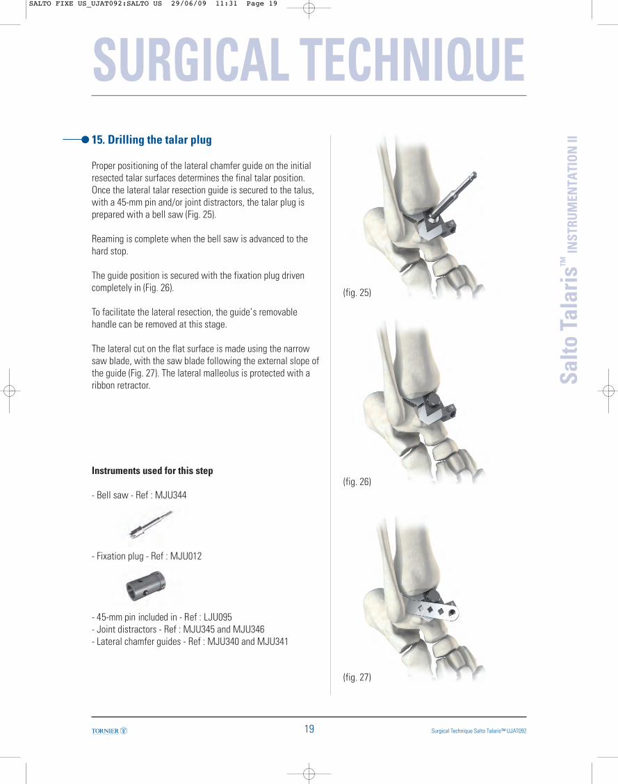
II15. Drilling the talar plug
Proper positioning of the lateral chamfer guide on the initialresected talar surfaces determines the final talar position.Once the lateral talar resection guide is secured to the talus,with a 45-mm pin and/or joint distractors, the talar plug isprepared with a bell saw (Fig. 25).
Reaming is complete when the bell saw is advanced to thehard stop.
The guide position is secured with the fixation plug drivencompletely in (Fig. 26).
To facilitate the lateral resection, the guide’s removablehandle can be removed at this stage.
The lateral cut on the flat surface is made using the narrowsaw blade, with the saw blade following the external slope ofthe guide (Fig. 27). The lateral malleolus is protected with aribbon retractor.
Instruments used for this step
- Bell saw - Ref : MJU344
- Fixation plug - Ref : MJU012
- 45-mm pin included in - Ref : LJU095- Joint distractors - Ref : MJU345 and MJU346- Lateral chamfer guides - Ref : MJU340 and MJU341
(fig. 25)
(fig. 26)
(fig. 27)
SALTO FIXE US_UJAT092:SALTO US 29/06/09 11:31 Page 19
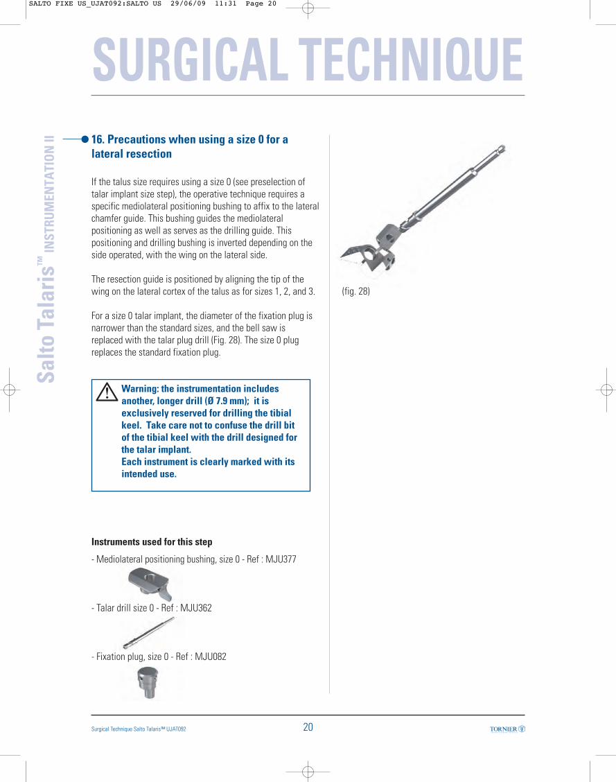
16. Precautions when using a size 0 for alateral resection
If the talus size requires using a size 0 (see preselection oftalar implant size step), the operative technique requires aspecific mediolateral positioning bushing to affix to the lateralchamfer guide. This bushing guides the mediolateralpositioning as well as serves as the drilling guide. Thispositioning and drilling bushing is inverted depending on theside operated, with the wing on the lateral side.
The resection guide is positioned by aligning the tip of thewing on the lateral cortex of the talus as for sizes 1, 2, and 3.
For a size 0 talar implant, the diameter of the fixation plug isnarrower than the standard sizes, and the bell saw isreplaced with the talar plug drill (Fig. 28). The size 0 plugreplaces the standard fixation plug.
Warning: the instrumentation includesanother, longer drill (Ø 7.9 mm); it is exclusively reserved for drilling the tibial keel. Take care not to confuse the drill bit of the tibial keel with the drill designed for the talar implant. Each instrument is clearly marked with itsintended use.
Instruments used for this step
- Mediolateral positioning bushing, size 0 - Ref : MJU377
- Talar drill size 0 - Ref : MJU362
- Fixation plug, size 0 - Ref : MJU082
SURGICAL TECHNIQUE
20
Salto
Tal
aris
™IN
STRU
MEN
TATI
ON
II
Surgical Technique Salto Talaris™ UJAT092
(fig. 28)
SALTO FIXE US_UJAT092:SALTO US 29/06/09 11:31 Page 20
SURGICAL TECHNIQUE
21 Surgical Technique Salto Talaris™ UJAT092
Salto
Tal
aris
™IN
STRU
MEN
TATI
ON
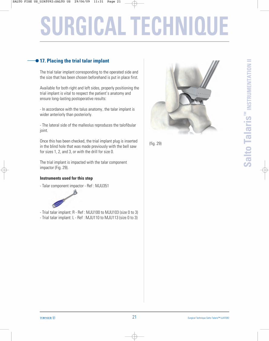
II17. Placing the trial talar implant
The trial talar implant corresponding to the operated side andthe size that has been chosen beforehand is put in place first.
Available for both right and left sides, properly positioning thetrial implant is vital to respect the patient’s anatomy andensure long-lasting postoperative results:
- In accordance with the talus anatomy, the talar implant iswider anteriorly than posteriorly.
- The lateral side of the malleolus reproduces the talofibularjoint.
Once this has been checked, the trial implant plug is insertedin the blind hole that was made previously with the bell sawfor sizes 1, 2, and 3, or with the drill for size 0.
The trial implant is impacted with the talar componentimpactor (Fig. 29).
Instruments used for this step
- Talar component impactor - Ref : MJU351
- Trial talar implant: R - Ref : MJU100 to MJU103 (size 0 to 3)- Trial talar implant: L - Ref : MJU110 to MJU113 (size 0 to 3)
(fig. 29)
SALTO FIXE US_UJAT092:SALTO US 29/06/09 11:31 Page 21
SURGICAL TECHNIQUE
22
Salto
Tal
aris
™IN
STRU
MEN
TATI
ON
II
Surgical Technique Salto Talaris™ UJAT092
(fig. 30)
(fig. 31)
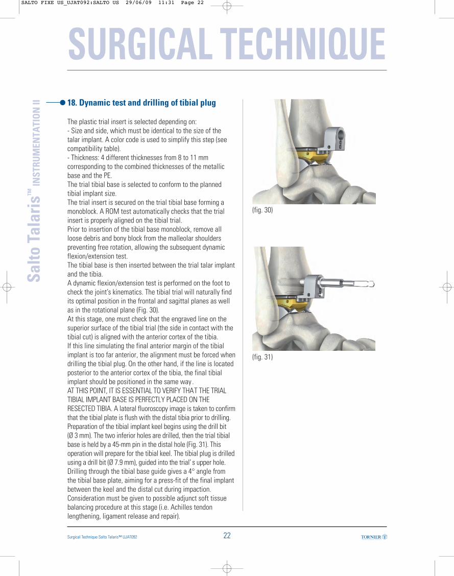
18. Dynamic test and drilling of tibial plug
The plastic trial insert is selected depending on: - Size and side, which must be identical to the size of thetalar implant. A color code is used to simplify this step (seecompatibility table).- Thickness: 4 different thicknesses from 8 to 11 mmcorresponding to the combined thicknesses of the metallicbase and the PE.The trial tibial base is selected to conform to the plannedtibial implant size.The trial insert is secured on the trial tibial base forming amonoblock. A ROM test automatically checks that the trialinsert is properly aligned on the tibial trial.Prior to insertion of the tibial base monoblock, remove allloose debris and bony block from the malleolar shoulderspreventing free rotation, allowing the subsequent dynamicflexion/extension test. The tibial base is then inserted between the trial talar implantand the tibia.A dynamic flexion/extension test is performed on the foot tocheck the joint’s kinematics. The tibial trial will naturally findits optimal position in the frontal and sagittal planes as wellas in the rotational plane (Fig. 30).At this stage, one must check that the engraved line on thesuperior surface of the tibial trial (the side in contact with thetibial cut) is aligned with the anterior cortex of the tibia.If this line simulating the final anterior margin of the tibialimplant is too far anterior, the alignment must be forced whendrilling the tibial plug. On the other hand, if the line is locatedposterior to the anterior cortex of the tibia, the final tibialimplant should be positioned in the same way . AT THIS POINT, IT IS ESSENTIAL TO VERIFY THAT THE TRIALTIBIAL IMPLANT BASE IS PERFECTLY PLACED ON THERESECTED TIBIA. A lateral fluoroscopy image is taken to confirmthat the tibial plate is flush with the distal tibia prior to drilling.Preparation of the tibial implant keel begins using the drill bit (Ø 3 mm). The two inferior holes are drilled, then the trial tibialbase is held by a 45-mm pin in the distal hole (Fig. 31). Thisoperation will prepare for the tibial keel. The tibial plug is drilledusing a drill bit (Ø 7.9 mm), guided into the trial’ s upper hole.Drilling through the tibial base guide gives a 4° angle fromthe tibial base plate, aiming for a press-fit of the final implantbetween the keel and the distal cut during impaction. Consideration must be given to possible adjunct soft tissuebalancing procedure at this stage (i.e. Achilles tendonlengthening, ligament release and repair).
SALTO FIXE US_UJAT092:SALTO US 29/06/09 11:31 Page 22
SURGICAL TECHNIQUE
23 Surgical Technique Salto Talaris™ UJAT092
Salto
Tal
aris
™IN
STRU
MEN
TATI
ON
II
Tibialpart
Insert
Talarpart
0 1 2 3
00 0 1 2 3
0 1 2 3
Instruments used for this step
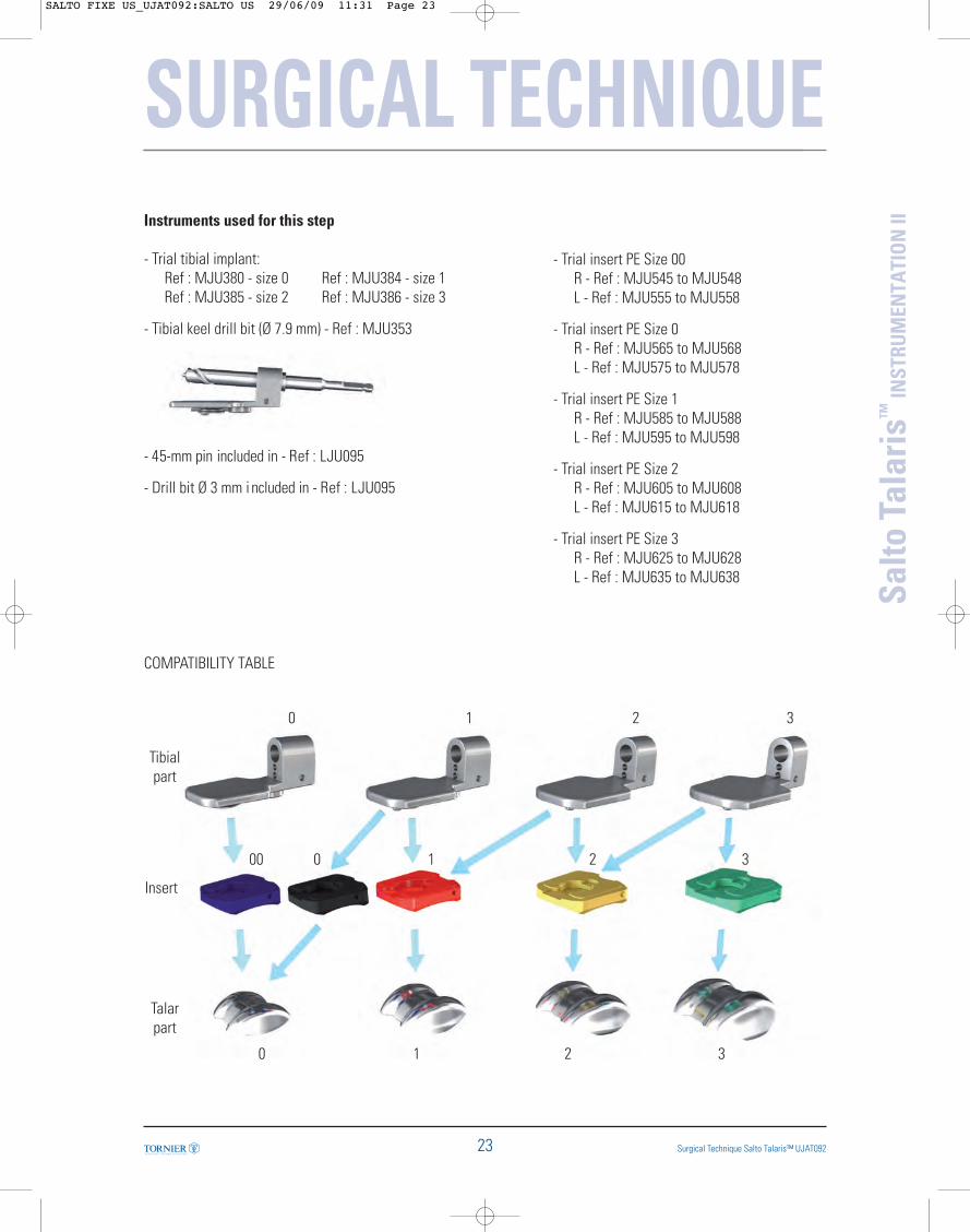
- Trial tibial implant: Ref : MJU380 - size 0 Ref : MJU384 - size 1Ref : MJU385 - size 2 Ref : MJU386 - size 3
- Tibial keel drill bit (Ø 7.9 mm) - Ref : MJU353
- 45-mm pin included in - Ref : LJU095
- Drill bit Ø 3 mm i ncluded in - Ref : LJU095
COMPATIBILITY TABLE
- Trial insert PE Size 00R - Ref : MJU545 to MJU548L - Ref : MJU555 to MJU558
- Trial insert PE Size 0R - Ref : MJU565 to MJU568L - Ref : MJU575 to MJU578
- Trial insert PE Size 1R - Ref : MJU585 to MJU588L - Ref : MJU595 to MJU598
- Trial insert PE Size 2R - Ref : MJU605 to MJU608L - Ref : MJU615 to MJU618
- Trial insert PE Size 3R - Ref : MJU625 to MJU628L - Ref : MJU635 to MJU638
SALTO FIXE US_UJAT092:SALTO US 29/06/09 11:31 Page 23

19. Finishing touches on the tibial keel
Once the plug has been placed, the trial insert monoblock isremoved.The tibial holes are connected using a small osteotome; thenthe thickness and depth of the engraved line are checked withthe graduated osteotome. The distal part of the anterior groove of the tibia is beveledusing the rasp, so that the tibial implant lies flush on theresection (Fig. 32).Inadequate rounding of the edges will potentially cause thetibia to split at the time of tibial component implantation, orresult in posterior gap or angulation of the tibial componentas seen on lateral view.With the different tibial implant sizes (0, 1, 2 , and 3) markedon the upper surface of the rasp, the trimming done in thismanner perfectly matches the length of the implant selected. The trial talar implant is then withdrawn.
Instruments used for this step
- Tibial keel graduated osteotome - Ref : MJU387
- Rasp - Ref : MJU350
- Osteotome - Ref : MJU357
(fig. 32)
Tibial keelroundedshape
SURGICAL TECHNIQUE
24
Salto
Tal
aris
™IN
STRU
MEN
TATI
ON
II
Surgical Technique Salto Talaris™ UJAT092
SALTO FIXE US_UJAT092:SALTO US 29/06/09 11:31 Page 24

SURGICAL TECHNIQUE
25 Surgical Technique Salto Talaris™ UJAT092
Salto
Tal
aris
™IN
STRU
MEN
TATI
ON
II20. Placing final implants
Recommendation: the final implants shouldbe positioned identically to the trialimplants. Prepare the bone and implantsurfaces with cement before placing the finalimplants.
1 – The talar implant is placed first, following the sameprocedure as described during the placement of the trial talarimplant. It is impacted with the talar component impactor (Fig.33). The size and side selected during the implant trials must beretained. 2 –The final PE and tibial implant form a single-block unitand therefore they should be assembled with the implantassembly clamp available in the instrument set.
ASSEMBLY OF THE INSERT ON THE TIBIAL IMPLANTThe implant assembly clamp has two distinct parts (Fig. 34):- the first one has a system to maintain the final tibial base;- the second one has a hood or mobile metallic jaw .The keel of the tibial implant is slipped onto the longeststump until contact is made with the posterior edge of theimplant with the clamp.The PE insert is manually slipped on the central fixation gutterand pushed until translation movement is no longer possible(Fig. 35).
Instruments used for this step
- Assembly clamp - Ref : MJU091
- Talar component impactor - Ref : MJU351
(fig. 33)
(fig. 34)
(fig. 35)
Maintains the tibial base
Mobile hoodor metallicjaw
SALTO FIXE US_UJAT092:SALTO US 29/06/09 11:31 Page 25
SURGICAL TECHNIQUE
26
Salto
Tal
aris
™IN
STRU
MEN
TATI
ON
II
Surgical Technique Salto Talaris™ UJAT092
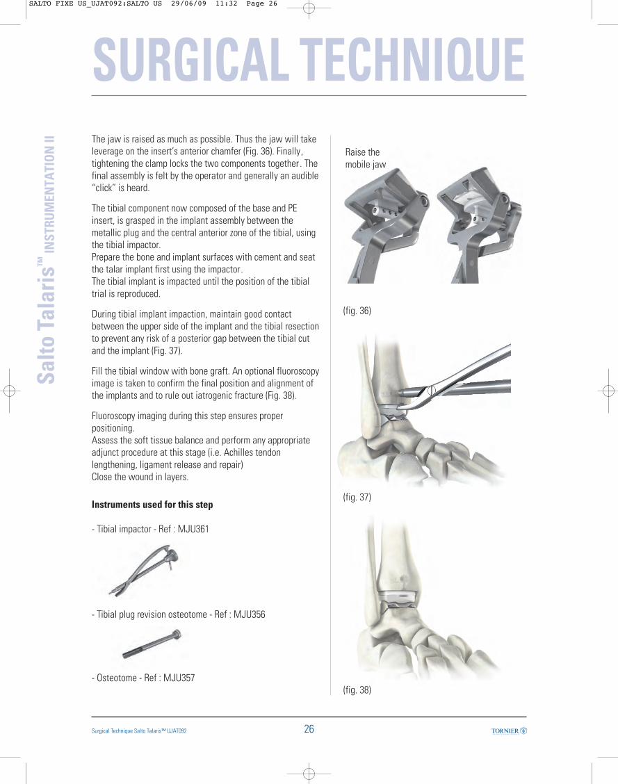
The jaw is raised as much as possible. Thus the jaw will takeleverage on the insert’s anterior chamfer (Fig. 36). Finally,tightening the clamp locks the two components together . Thefinal assembly is felt by the operator and generally an audible“click” is heard.
The tibial component now composed of the base and PEinsert, is grasped in the implant assembly between themetallic plug and the central anterior zone of the tibial, usingthe tibial impactor.Prepare the bone and implant surfaces with cement and seatthe talar implant first using the impactor. The tibial implant is impacted until the position of the tibialtrial is reproduced.
During tibial implant impaction, maintain good contactbetween the upper side of the implant and the tibial resectionto prevent any risk of a posterior gap between the tibial cutand the implant (Fig. 37).
Fill the tibial window with bone graft. An optional fluoroscopyimage is taken to confirm the final position and alignment ofthe implants and to rule out iatrogenic fracture (Fig. 38).
Fluoroscopy imaging during this step ensures properpositioning.Assess the soft tissue balance and perform any appropriateadjunct procedure at this stage (i.e. Achilles tendonlengthening, ligament release and repair)Close the wound in layers.
Instruments used for this step
- Tibial impactor - Ref : MJU361
- Tibial plug revision osteotome - Ref : MJU356
- Osteotome - Ref : MJU357
(fig. 36)
Raise themobile jaw
(fig. 37)
(fig. 38)
SALTO FIXE US_UJAT092:SALTO US 29/06/09 11:32 Page 26
27
SURGICAL TECHNIQUE
Surgical Technique Salto Talaris™ UJAT092
Salto
Tal
aris
™IN
STRU
MEN
TATI
ON
II21. Rehabilitation protocol
Different steps have to be followed after surgery :- Splint in neutral position- Remove sutures and evaluate wound at 2-3 weeks- < 3 weeks
- Cast or splint- Non-weight bearing
- 3-6 weeks- Cast boot- Non-weight bearing- Self-directed ROM
- 7th week- Cast boot or ankle brace/shoe- Weight bearing as tolerated- Physical therapy for ROM, resistive strengthening
Associated procedures performed along with the arthroplastysuch as Achilles tendon lengthening may require arehabilitation protocol appropriate to the associatedprocedure.
SALTO FIXE US_UJAT092:SALTO US 29/06/09 11:32 Page 27

28Surgical Technique Salto Talaris™ UJAT092
Salto
Tal
aris
™IN
STRU
MEN
TATI
ON
II
SURGICAL TECHNIQUE22. Revising or removing implants
If the implant must be revised, revision should begin byremoving the PE insert.This is disassembled from the tibial base by inserting thetibial insert extractor blade between the base and the PE. Atowel clamp holds the PE component for its extraction, after alever maneuver using the extractor has separated the twocomponents.
If necessary, the tibial base can then be removed as follows:- To precut the bone around the tibial plug, use the tibial plugrevision osteotome and osteotome provided for this purposein the instrumentation.- Hook the posterior aspect of the tibial implant with the tibialcomponent extractor. - Insert the extractor plug by screwing the slap hammer onthe tibial extractor.- Push and pull vigorously with the slap hammer until theimplant is fully removed. The talar implant is separated from the talus with theosteotome.
Instruments used for this step
- Insert extractor – Ref : MJU058
- Tibial component extractor - Ref : MJU368
- Slap hammer - Ref : MJU358
- Osteotomes - Ref : MJU356 and MJU357
SALTO FIXE US_UJAT092:SALTO US 29/06/09 11:32 Page 28
29 Surgical Technique Salto Talaris™ UJAT092
Salto
Tal
aris
™IN
STRU
MEN
TATI
ON
II
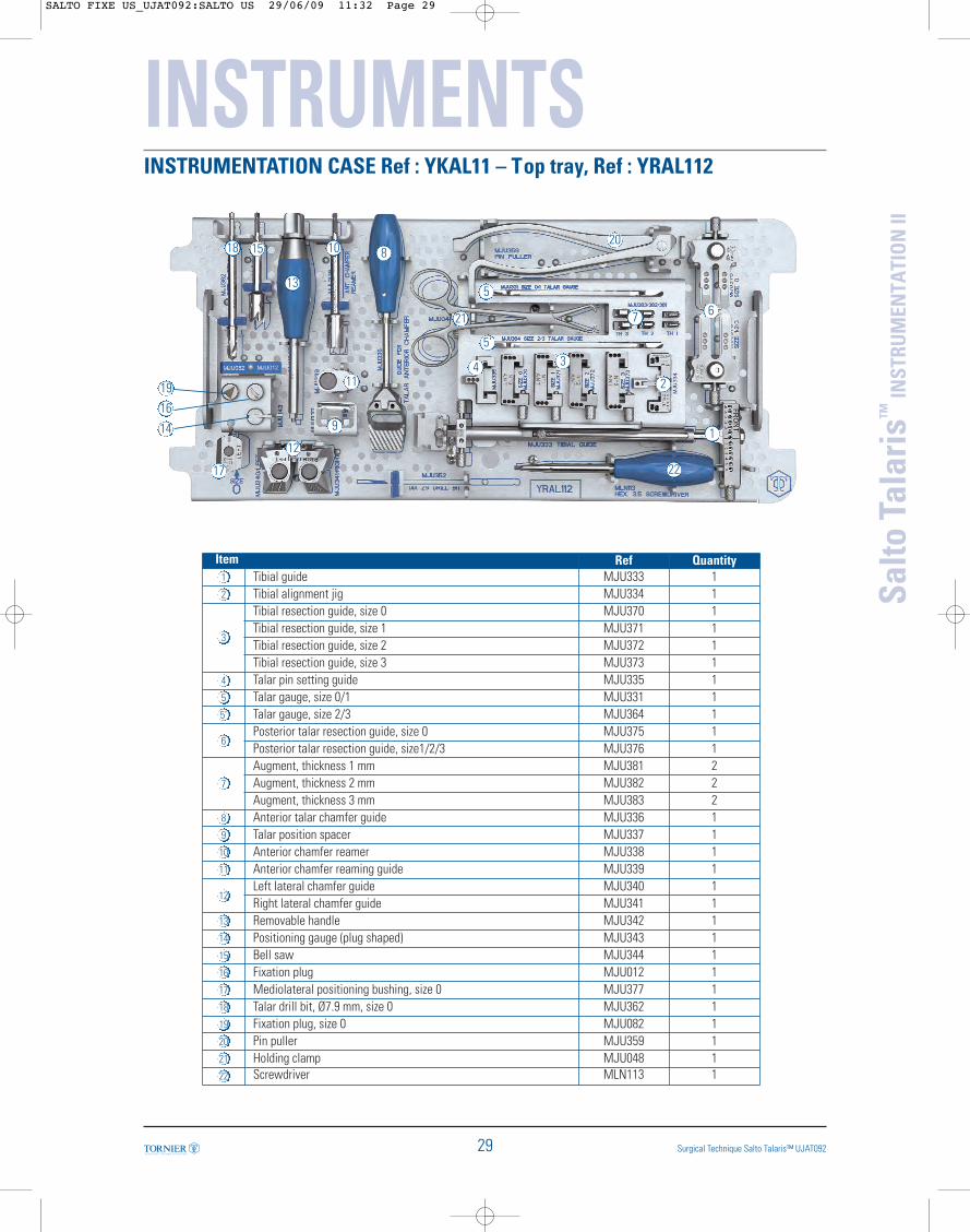
INSTRUMENTATION CASE Ref : YKAL11 – Top tray, Ref : YRAL112
INSTRUMENTS
1
2
34
5
5’
67
8
9
10
11
12
13
19
14
16
15
17
1820
21
22
Item Ref Quantity1 Tibial guide MJU333 12 Tibial alignment jig MJU334 1
3
Tibial resection guide, size 0 MJU370 1Tibial resection guide, size 1 MJU371 1Tibial resection guide, size 2 MJU372 1Tibial resection guide, size 3 MJU373 1
4 Talar pin setting guide MJU335 15 Talar gauge, size 0/1 MJU331 15’ Talar gauge, size 2/3 MJU364 1
6Posterior talar resection guide, size 0 MJU375 1Posterior talar resection guide, size1/2/3 MJU376 1
7
Augment, thickness 1 mm MJU381 2Augment, thickness 2 mm MJU382 2Augment, thickness 3 mm MJU383 2
8 Anterior talar chamfer guide MJU336 19 Talar position spacer MJU337 110 Anterior chamfer reamer MJU338 111 Anterior chamfer reaming guide MJU339 1
12Left lateral chamfer guide MJU340 1Right lateral chamfer guide MJU341 1
13 Removable handle MJU342 114 Positioning gauge (plug shaped) MJU343 115 Bell saw MJU344 116 Fixation plug MJU012 117 Mediolateral positioning bushing, size 0 MJU377 118 Talar drill bit, Ø7.9 mm, size 0 MJU362 119 Fixation plug, size 0 MJU082 120 Pin puller MJU359 121 Holding clamp MJU048 122 Screwdriver MLN113 1
SALTO FIXE US_UJAT092:SALTO US 29/06/09 11:32 Page 29
INSTRUMENTS
30
Salto
Tal
aris
™IN
STRU
MEN
TATI
ON
II
Surgical Technique Salto Talaris™ UJAT092
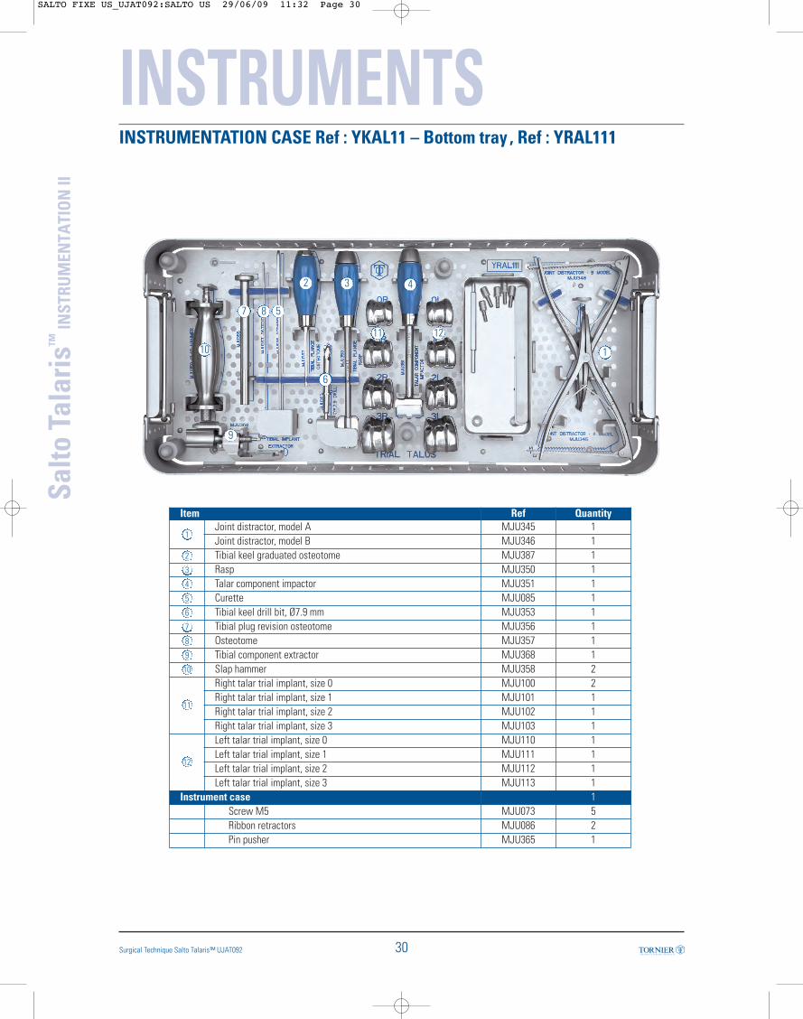
INSTRUMENTATION CASE Ref : YKAL11 – Bottom tray , Ref : YRAL111
1
2 3 4
587
10
9
6
11 12
Item Ref Quantity
1Joint distractor, model A MJU345 1Joint distractor, model B MJU346 1
2 Tibial keel graduated osteotome MJU387 13 Rasp MJU350 14 Talar component impactor MJU351 15 Curette MJU085 16 Tibial keel drill bit, Ø7.9 mm MJU353 17 Tibial plug revision osteotome MJU356 18 Osteotome MJU357 19 Tibial component extractor MJU368 110 Slap hammer MJU358 2
11
Right talar trial implant, size 0 MJU100 2Right talar trial implant, size 1 MJU101 1Right talar trial implant, size 2 MJU102 1Right talar trial implant, size 3 MJU103 1
12
Left talar trial implant, size 0 MJU110 1Left talar trial implant, size 1 MJU111 1Left talar trial implant, size 2 MJU112 1Left talar trial implant, size 3 MJU113 1
Instrument case 1Screw M5 MJU073 5Ribbon retractors MJU086 2Pin pusher MJU365 1
SALTO FIXE US_UJAT092:SALTO US 29/06/09 11:32 Page 30

31
Salto
Tal
aris
™IN
STRU
MEN
TATI
ON
II
Surgical Technique Salto Talaris™ UJAT092
REMOVABLE CASE Ref : YKAL13 – Tray Ref : YRAL13
INSTRUMENTS
1
2
34
56
Item Ref Quantity
1 Assembly clamp MJU091 12 Tibial Impactor MJU361 13 Insert extractor MJU058 1
4
Tibial trial size 0 MJU380 1Tibial trial size 1 MJU384 1Tibial trial size 2 MJU385 1Tibial trial size 3 MJU386 1
5
Insert trial Right size 00 th 8 MJU545 1Insert trial Right size 00 th 9 MJU546 1Insert trial Right size 00 th 10 MJU547 1Insert trial Right size 00 th 11 MJU548 1Insert trial Right size 0 th 8 MJU565 1Insert trial Right size 0 th 9 MJU566 1Insert trial Right size 0 th 10 MJU567 1Insert trial Right size 0 th 11 MJU568 1Insert trial Right size 1 th 8 MJU585 1Insert trial Right size 1 th 9 MJU586 1Insert trial Right size 1 th 10 MJU587 1Insert trial Right size 1 th 11 MJU588 1Insert trial Right size 2 th 8 MJU605 1Insert trial Right size 2 th 9 MJU606 1Insert trial Right size 2 th 10 MJU607 1Insert trial Right size 2 th 11 MJU608 1Insert trial Right size 3 th 8 MJU625 1
Item Ref Quantity
5
Insert trial Right size 3 th 9 MJU626 1Insert trial Right size 3 th 10 MJU627 1Insert trial Right size 3 th 11 MJU628 1
6
Insert trial Left size 00 th 8 MJU555 1Insert trial Left size 00 th 9 MJU556 1Insert trial Left size 00 th 10 MJU557 1Insert trial Left size 00 th 11 MJU558 1Insert trial Left size 0 th 8 MJU575 1Insert trial Left size 0 th 9 MJU576 1Insert trial Left size 0 th 10 MJU577 1Insert trial Left size 0 th 11 MJU578 1Insert trial Left size 1 th 8 MJU595 1Insert trial Left size 1 th 9 MJU596 1Insert trial Left size 1 th 10 MJU597 1Insert trial Left size 1 th 11 MJU598 1Insert trial Left size 2 th 8 MJU615 1Insert trial Left size 2 th 9 MJU616 1Insert trial Left size 2 th 10 MJU617 1Insert trial Left size 2 th 11 MJU618 1Insert trial Left size 3 th 8 MJU635 1Insert trial Left size 3 th 9 MJU636 1Insert trial Left size 3 th 10 MJU637 1Insert trial Left size 3 th 11 MJU638 1
SALTO FIXE US_UJAT092:SALTO US 29/06/09 11:32 Page 31

32
Salto
Tal
aris
™IN
STRU
MEN
TATI
ON
II
Surgical Technique Salto Talaris™ UJAT092
SAW BLADES
SINGLE USE ITEMSHub Connector System 70mm long x 8 - 13mm wide x
1.27mm thick90mm long x 13 - 21mm wide x
1.27mm thick
Narrow saw blade Wide saw blade
Stryker- EHD & Systems2000,4,5 SAW608 SAW721
Linvatec / Hall-Power Pro /Versipower Plus SAW614 SAW723
Linvatec / Hall- Versipower SAW609 SAW724
The following saw blades are special order items and available only by contacting Tornier
Customer Service.
PIN PACK
Sterile Single Use Pin Pack : LJU095
3 x 110-mm self-drilling pins
5 x 75-mm pins
3 x 45-mm pins
1 x drill bit ø 3 mm
SALTO FIXE US_UJAT092:SALTO US 29/06/09 11:32 Page 32

IMPLANTS
T I B I A L C O M P O N E N T S - C o C r
Left Right
Size 0 LJU210 LJU200
Size 1 LJU211 LJU201
Size 2 LJU212 LJU202
Size 3 LJU213 LJU203
TALAR COMPONENTS - CoCr
INSERTS - UHMWPEThickness Left Right
Size 00 8 mm LJU418 LJU408
9 mm LJU419 LJU409
10 mm LJU420 LJU410
11 mm LJU421 LJU411
Size 0 8 mm LJU225 LJU215
9 mm LJU226 LJU216
10 mm LJU227 LJU217
11 mm LJU228 LJU218
Size 1 8 mm LJU245 LJU235
9 mm LJU246 LJU236
10 mm LJU247 LJU237
11 mm LJU248 LJU238
Size 2 8 mm LJU265 LJU255
9 mm LJU266 LJU256
10 mm LJU267 LJU257
11 mm LJU268 LJU258
Size 3 8 mm LJU285 LJU275
9 mm LJU286 LJU276
10 mm LJU287 LJU277
11 mm LJU288 LJU278
References
Size 0 LJU220
Size 1 LJU221
Size 2 LJU222
Size 3 LJU223
33Surgical Technique Salto Talaris™ UJTT091
Salto
Tal
aris
™IN
STRU
MEN
TATI
ON
II

UJAT 092
Tornier is a registered trademarks of Tornier, SA.
Salto and Salto Talaris are covered by US patent # 6,183,519.
Tornier, Inc. // Edina, MN 55435 // +1 888 867 6437 // +1 281 494 7900 // www.tornier-us.com