user manual - simpro€¦ · 2 introduction congratulations on your purchase of a dumpmaster...
TRANSCRIPT
© Simpro Handling Equipment Ltd 2017
66 Rangi Road, Takanini 2105 | PO Box 202236, Southgate, Takanini 2246 | Auckland, New Zealand
USER MANUAL
S i m p r o D u m p m a s t e r

Copyright © 2017 Simpro Handling Equipment Ltd.
No part of this document may be reproduced or transmitted in any form or by any means,
electronic, mechanical, photocopying, recording, or otherwise, without the written
permission of the publisher.
For reasons of standards compliance and international conformity, this document uses
Système International (SI) units. These may be converted to their Imperial equivalents as
follows:
1 kilogram (kg) = 2.2 pounds (lb)
1 metre (m) = 1000 millimetres (mm) = 39.37 inches (in) = 3.28 feet (ft) = 1.09 yards (yd)
The following textual conventions are used throughout this document:
Text in GREEN indicates a point of interest.
Text in RED indicates a point of warning, or a safety hazard.
Any errors in this document should be reported by email to [email protected]
User Manual | Simpro Dumpmaster
v43.0 | November 2017 | Page 2
1 Contents
1 Contents ............................................................................................................................ 3
2 Introduction ....................................................................................................................... 5
2.1 Key features ................................................................................................................................ 5
2.2 Construction ............................................................................................................................... 5
2.3 Mechanism ................................................................................................................................. 5
2.4 Assembly ..................................................................................................................................... 6
2.5 Environmental restrictions ........................................................................................................ 6
2.6 Intended operational life ......................................................................................................... 6
2.7 Notes ............................................................................................................................................ 6
3 Safety ................................................................................................................................. 7
3.1 Safety features ........................................................................................................................... 7
3.2 Reasonably foreseeable misuse ............................................................................................. 7
3.3 Hazard and Risk Assessment guide ........................................................................................ 7
3.3.1 Risk Factor Calculation ..................................................................................... 8
3.3.2 Risk Factor Evaluation ....................................................................................... 8
3.3.3 Identified Hazards .............................................................................................. 9
3.3.4 Residual Hazards .............................................................................................. 12
3.4 Recommended Precautions ................................................................................................. 13
4 Operating Instructions ................................................................................................... 15
4.1 Before operation...................................................................................................................... 15
4.2 Operation (standard machine) ............................................................................................ 15
4.3 Operation (autocycle machine).......................................................................................... 16
4.3.1 Automatic mode ............................................................................................. 16
4.3.2 Manual mode .................................................................................................. 16
5 Maintenance Procedures ............................................................................................. 17
5.1 Quick Troubleshooting Guide ............................................................................................... 17
5.2 Cleaning .................................................................................................................................... 18
5.2.1 Ingress protection ............................................................................................ 18
5.3 Cradle jams............................................................................................................................... 18
5.3.1 Cradle jams while raising ................................................................................ 18
5.3.2 Cradle jams while lowering ............................................................................ 18
5.4 Battery and charger ............................................................................................................... 21
5.4.1 Battery indicator .............................................................................................. 21
User Manual | Simpro Dumpmaster
v43.0 | November 2017 | Page 4
5.4.2 Charging ........................................................................................................... 22
5.4.3 Maintenance ................................................................................................... 22
5.4.4 Battery storage ................................................................................................ 22
5.5 Hydraulic system ...................................................................................................................... 23
5.5.1 Powerpack ....................................................................................................... 23
5.5.2 Control valves .................................................................................................. 23
5.5.3 Lift Rams ............................................................................................................ 23
5.5.4 Maintenance ................................................................................................... 23
5.5.5 Hydraulic fluid .................................................................................................. 23
5.5.6 Hydraulic system schematic .......................................................................... 24
5.6 Safety Door ............................................................................................................................... 25
5.6.1 Side-hinge door ............................................................................................... 25
5.6.2 Lift-up door ....................................................................................................... 25
5.7 Safety Door Interlock .............................................................................................................. 25
5.7.1 Manual override .............................................................................................. 27
5.8 Raised-cradle maintenance ................................................................................................. 27
6 Handling, transportation and storage ......................................................................... 28
6.1 Moving ....................................................................................................................................... 28
6.2 Lifting .......................................................................................................................................... 28
6.3 Transportation........................................................................................................................... 28
6.4 Storage ...................................................................................................................................... 28
7 Safety Monitoring System .............................................................................................. 29
7.1 Overview ................................................................................................................................... 29
7.2 440C-CR30 Safety relay .......................................................................................................... 29
7.2.1 Troubleshooting ............................................................................................... 30
7.2.2 Configuration ................................................................................................... 30
8 Common Spare Parts..................................................................................................... 31
9 Warranty .......................................................................................................................... 33
10 EC Declaration of Conformity .................................................................................. 35
11 Scheduled Inspections............................................................................................... 37
11.1 Preinspection checklist ........................................................................................................... 37
11.2 Weekly inspection ................................................................................................................... 37
11.3 Monthly inspection .................................................................................................................. 39
11.4 Annual inspection .................................................................................................................... 41
2 Introduction
Congratulations on your purchase of a Dumpmaster bin-tipping machine from Simpro. The
tipping action of the Dumpmaster is the safest, most efficient and easy-to-use such system in
the world. The Dumpmaster is very versatile and can be used in numerous applications,
ranging from emptying rubbish bins into skips to pouring food ingredients into hoppers or
mixers.
No matter what the application, the Dumpmaster has proven to be safe, reliable and
economical to operate, year after year.
2.1 Key features Key features of the Dumpmaster include:
1. A unique tipping action whereby bins are lifted straight up, and then gently rolled
forward around the lip of the skip or hopper being emptied into. Benefits of this design
include a small ‘footprint’, and a wide range of tipping heights available, from
700mm to 7 metres and more.
2. A huge weight capacity of up to 250kg.
3. An extremely reliable, virtually maintenance-free design.
4. The standard Dumpmaster has a fully hot-dip galvanised frame and cradle, and is
also available in full or partial stainless steel for hygiene-critical areas.
5. The basic design can be modified to suit a wide range of bin sizes, shapes, and
weights.
6. Most standard bins do not require clamping or retaining – simply place on the cradle
and press the ‘Raise’ button.
2.2 Construction The Dumpmaster machine consists of a steel or stainless-steel frame with vertical masts and
stabilizing legs, a bin cradle, one hydraulic ram, guarding, castor wheels, powerpack cover,
control panel, power lead or battery, hydraulic powerpack and electronic control systems.
2.3 Mechanism When operated, the bin cradle moves vertically in the masts, and is inverted at the
appropriate height by an arrangement of arms, rollers, and a curved track. A hydraulic ram
provides the force to lift and empty the bin. The ram is supplied by a hydraulic power pack,
which may have a 3-phase, 1-phase, battery, or compressed-air motor. Electrical, hydraulic,
and / or mechanical control mechanisms allow the operator to raise or lower the bin in a
controlled manner.
User Manual | Simpro Dumpmaster
v43.0 | November 2017 | Page 6
2.4 Assembly The Dumpmaster is usually delivered fully assembled. However, in some cases guarding
panels may be removed to minimise volume for shipping. Assembly instructions can be
viewed at the following link: https://goo.gl/53XAd7.
2.5 Environmental restrictions
The Dumpmaster may be used indoors or outdoors. However, some restrictions apply:
1. A minimum floor area of two square metres, with a clear passage to exits;
2. Height above sea level not more than 1000m;
3. Ambient temperature not higher than +40℃ and not lower than -10℃;
4. At ambient temperatures above 35℃, the relative humidity should not exceed 50%; at
lower temperatures, higher relative humidity is permitted;
5. Do not use in flammable, explosive, corrosive, acidic or alkaline environments.
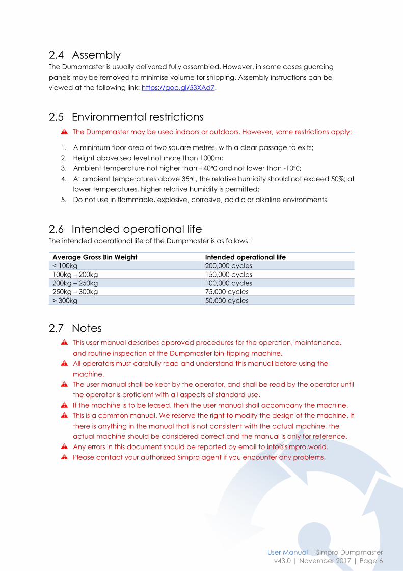
2.6 Intended operational life The intended operational life of the Dumpmaster is as follows:
Average Gross Bin Weight Intended operational life
< 100kg 200,000 cycles
100kg – 200kg 150,000 cycles
200kg – 250kg 100,000 cycles
250kg – 300kg 75,000 cycles
> 300kg 50,000 cycles
2.7 Notes
This user manual describes approved procedures for the operation, maintenance,
and routine inspection of the Dumpmaster bin-tipping machine.
All operators must carefully read and understand this manual before using the
machine.
The user manual shall be kept by the operator, and shall be read by the operator until
the operator is proficient with all aspects of standard use.
If the machine is to be leased, then the user manual shall accompany the machine.
This is a common manual. We reserve the right to modify the design of the machine. If
there is anything in the manual that is not consistent with the actual machine, the
actual machine should be considered correct and the manual is only for reference.
Any errors in this document should be reported by email to [email protected].
Please contact your authorized Simpro agent if you encounter any problems.
3 Safety
The Dumpmaster has been designed to be as safe as possible without restricting the ease-of-
use and versatility of the machine.
A comprehensive Hazard and Risk Assessment must be undertaken before the
Dumpmaster is used for the first time, as described in Section 3.3.
3.1 Safety features The safety features of the Dumpmaster are as follows:
1. Welded mesh or sheet-metal panels prevent personnel access to all moving parts.
2. A safety interlock system which disables the machine unless the door is shut, and
electrically locks the door as soon as the cradle leaves the ground.
3. A tipping action which keep the weight of the bin within the machine footprint at all
times.
4. A pressure-compensating lowering valve which automatically regulates the lowering
speed regardless of the weight of the bin.
5. The machine is immediately shut down whenever the Raise or Lower button is
released.
6. Some models are fitted with an Emergency Stop button which immediately shuts
down the machine when pressed.
3.2 Reasonably foreseeable misuse The reasonably foreseeable misuse considered in the Dumpmaster design is as follows:
1. Use of the machine by untrained operators;
2. Tipping bins that the cradle is not specifically designed to hold;
3. Attempts to bypass door interlock or other safety systems;
4. Attempts to clear spilt product from under the cradle without following proper
procedures;
5. Attempts to clean the machine without following proper procedures.
3.3 Hazard and Risk Assessment guide Machinery owners are required by law to conduct a comprehensive Hazard and Risk
Assessment for their equipment, considering all relevant factors such as the area it is used,
the skill and training of operators, the proximity of other persons, frequency of use, etc.
The following section is not intended to be a comprehensive Hazard and Risk Assessment, but
an analysis of the most common risk factors associated with the Dumpmaster bin tipper.
As with all powered industrial equipment, some hazards remain, and it is essential that all
operators are aware of these hazards and what they must do to prevent harm to themselves
or to others, as described in Section 3.3.4.
User Manual | Simpro Dumpmaster
v43.0 | November 2017 | Page 8
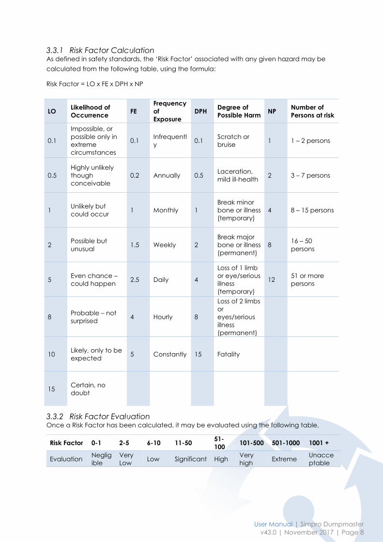
3.3.1 Risk Factor Calculation As defined in safety standards, the ‘Risk Factor’ associated with any given hazard may be
calculated from the following table, using the formula:
Risk Factor = LO x FE x DPH x NP
3.3.2 Risk Factor Evaluation Once a Risk Factor has been calculated, it may be evaluated using the following table.
LO Likelihood of
Occurrence FE
Frequency
of
Exposure
DPH Degree of
Possible Harm NP
Number of
Persons at risk
0.1
Impossible, or
possible only in
extreme
circumstances
0.1 Infrequentl
y 0.1
Scratch or
bruise 1 1 – 2 persons
0.5
Highly unlikely
though
conceivable
0.2 Annually 0.5 Laceration,
mild ill-health 2 3 – 7 persons
1 Unlikely but
could occur 1 Monthly 1
Break minor
bone or illness
(temporary)
4 8 – 15 persons
2 Possible but
unusual 1.5 Weekly 2
Break major
bone or illness
(permanent)
8 16 – 50
persons
5 Even chance –
could happen 2.5 Daily 4
Loss of 1 limb
or eye/serious
illness
(temporary)
12 51 or more
persons
8 Probable – not
surprised 4 Hourly 8
Loss of 2 limbs
or
eyes/serious
illness
(permanent)
10 Likely, only to be
expected 5 Constantly 15 Fatality
15 Certain, no
doubt
Risk Factor 0-1 2-5 6-10 11-50 51-
100 101-500 501-1000 1001 +
Evaluation Neglig
ible
Very
Low Low Significant High
Very
high Extreme
Unacce
ptable
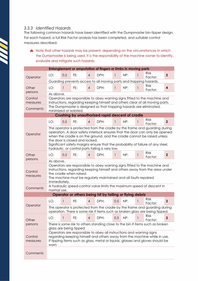
3.3.3 Identified Hazards The following common hazards have been identified with the Dumpmaster bin-tipper design.
For each hazard, a full Risk Factor analysis has been completed, and suitable control
measures described.
Note that other hazards may be present, depending on the circumstances in which
the Dumpmaster is being used. It is the responsibility of the machine owner to identify,
evaluate and mitigate such hazards.
Entanglement or amputation of fingers or limbs in moving parts
Operator LO: 0.5 FE: 4 DPH: 1 NP: 1
Risk
Factor: 2
Guarding prevents access to all moving parts and trapping hazards.
Other
persons
LO: 1 FE: 4 DPH: 1 NP: 1 Risk
Factor: 4
As above.
Control
measures
Operators are responsible to obey warning signs fitted to the machine and
instructions, regarding keeping himself and others clear of all moving parts.
Comments The Dumpmaster is designed so that trapping hazards are eliminated,
minimized or isolated.
Crushing by unauthorized rapid descent of cradle
Operator
LO: 0.5 FE: 4 DPH: 1 NP: 1 Risk
Factor: 2
The operator is protected from the cradle by the frame and guarding during
operation. A door safety interlock ensures that the door can only be opened
when the cradle is on the ground, and the cradle cannot be raised unless
the door is closed and locked.
Significant safety margins ensure that the probability of failure of any steel,
hydraulic, or control parts failing is very low.
Other
persons
LO: 0.5 FE: 4 DPH: 1 NP: 1 Risk
Factor: 2
As above.
Control
measures
Operators are responsible to obey warning signs fitted to the machine and
instructions, regarding keeping himself and others away from the area under
the cradle when raised.
The machine must be regularly maintained and all faults repaired
immediately.
Comments A hydraulic speed-control valve limits the maximum speed of descent in
normal use.
Operator or others being hit by falling or flying debris
Operator
LO: 1 FE: 4 DPH: 0.5 NP: 1 Risk
Factor: 2
The operator is protected from the cradle by the frame and guarding during
operation. There is some risk if items such as broken glass are being tipped.
Other
persons
LO: 1 FE: 4 DPH: 0.5 NP: 1 Risk
Factor: 2
There is some risk to others standing close to the bin if items such as broken
glass are being tipped
Control
measures
Operators are responsible to obey all instructions and warning signs
regarding keeping himself and others away from the machine while in use.
If tipping items such as glass, metal or liquids, glasses and gloves should be
worn
Comments
User Manual | Simpro Dumpmaster
v43.0 | November 2017 | Page 10
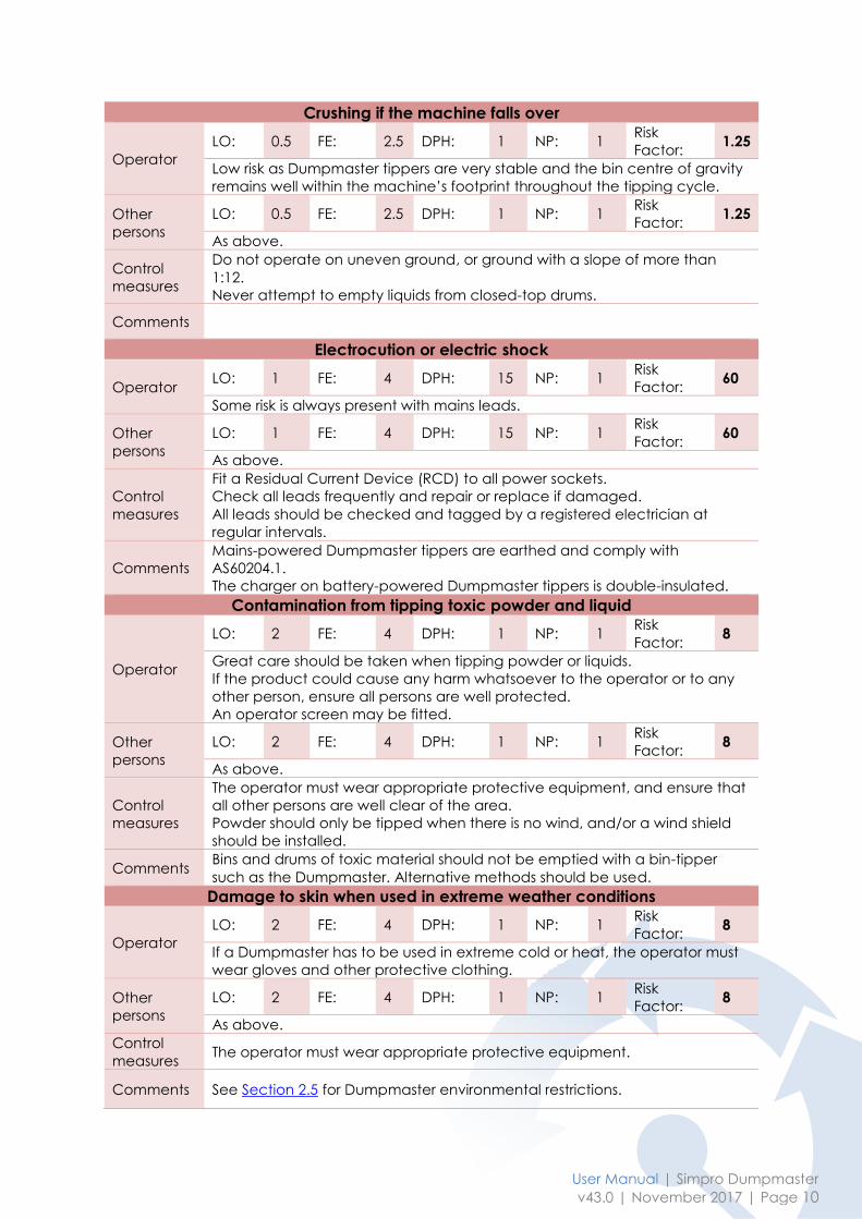
Crushing if the machine falls over
Operator
LO: 0.5 FE: 2.5 DPH: 1 NP: 1 Risk
Factor: 1.25
Low risk as Dumpmaster tippers are very stable and the bin centre of gravity
remains well within the machine’s footprint throughout the tipping cycle.
Other
persons
LO: 0.5 FE: 2.5 DPH: 1 NP: 1 Risk
Factor: 1.25
As above.
Control
measures
Do not operate on uneven ground, or ground with a slope of more than
1:12.
Never attempt to empty liquids from closed-top drums.
Comments
Electrocution or electric shock
Operator LO: 1 FE: 4 DPH: 15 NP: 1
Risk
Factor: 60
Some risk is always present with mains leads.
Other
persons
LO: 1 FE: 4 DPH: 15 NP: 1 Risk
Factor: 60
As above.
Control
measures
Fit a Residual Current Device (RCD) to all power sockets.
Check all leads frequently and repair or replace if damaged.
All leads should be checked and tagged by a registered electrician at
regular intervals.
Comments
Mains-powered Dumpmaster tippers are earthed and comply with
AS60204.1.
The charger on battery-powered Dumpmaster tippers is double-insulated.
Contamination from tipping toxic powder and liquid
Operator
LO: 2 FE: 4 DPH: 1 NP: 1 Risk
Factor: 8
Great care should be taken when tipping powder or liquids.
If the product could cause any harm whatsoever to the operator or to any
other person, ensure all persons are well protected.
An operator screen may be fitted.
Other
persons
LO: 2 FE: 4 DPH: 1 NP: 1 Risk
Factor: 8
As above.
Control
measures
The operator must wear appropriate protective equipment, and ensure that
all other persons are well clear of the area.
Powder should only be tipped when there is no wind, and/or a wind shield
should be installed.
Comments Bins and drums of toxic material should not be emptied with a bin-tipper
such as the Dumpmaster. Alternative methods should be used.
Damage to skin when used in extreme weather conditions
Operator
LO: 2 FE: 4 DPH: 1 NP: 1 Risk
Factor: 8
If a Dumpmaster has to be used in extreme cold or heat, the operator must
wear gloves and other protective clothing.
Other
persons
LO: 2 FE: 4 DPH: 1 NP: 1 Risk
Factor: 8
As above.
Control
measures The operator must wear appropriate protective equipment.
Comments See Section 2.5 for Dumpmaster environmental restrictions.
Application-specific hazard:
Operator
LO: FE: DPH: NP: Risk
Factor:
Other
persons
LO: FE: DPH: NP: Risk
Factor:
Control
measures
Comments
Application-specific hazard:
Operator
LO: FE: DPH: NP: Risk
Factor:
Other
persons
LO: FE: DPH: NP: Risk
Factor:
Control
measures
Comments
Application-specific hazard:
Operator
LO: FE: DPH: NP: Risk
Factor:
Other
persons
LO: FE: DPH: NP: Risk
Factor:
Control
measures
Comments
Application-specific hazard:
Operator
LO: FE: DPH: NP: Risk
Factor:
Other
persons
LO: FE: DPH: NP: Risk
Factor:
Control
measures
Comments
User Manual | Simpro Dumpmaster
v43.0 | November 2017 | Page 12
Application-specific hazard:
Operator
LO: FE: DPH: NP: Risk
Factor:
Other
persons
LO: FE: DPH: NP: Risk
Factor:
Control
measures
Comments
Application-specific hazard:
Operator
LO: FE: DPH: NP: Risk
Factor:
Other
persons
LO: FE: DPH: NP: Risk
Factor:
Control
measures
Comments
Application-specific hazard:
Operator
LO: FE: DPH: NP: Risk
Factor:
Other
persons
LO: FE: DPH: NP: Risk
Factor:
Control
measures
Comments
3.3.4 Residual Hazards Some hazards may be present despite any the safety measures implemented by the
manufacturer.
It is the responsibility of the owner and the operators to identify and evaluate any such
hazards, and to put in place procedures to ensure the safety of all persons near the
machine. These steps may include any or all of the following:
Training of operators.
Testing and recording that operators are properly trained.
Implementing Standard Operating Procedures and ensuring they are followed.
Posting additional signage, floor marking, or other warnings as deemed appropriate.

3.4 Recommended Precautions The following precautions must be taken for the safe use of a Dumpmaster bin tipper.
Only trained and authorised operators should be permitted to use the machine.
Operators must read and obey the instructions displayed on the machine.
Never operate machine on ground with a slope ratio greater than 1:12.
Never operate machine on the edge of a raised dock or platform, unless designed for that application.
Never operate machine with any covers or guards removed.
Never attempt to empty the contents of closed-top drums unless the machine is securely bolted down.
All persons other than the operator must keep at least two metres clear while the machine is in use.
Always keep feet and hands well clear of bin and cradle when operating.
Do not place feet or foreign objects under the side guards or door.
Do not empty bins if over-filled.
User Manual | Simpro Dumpmaster
v43.0 | November 2017 | Page 14
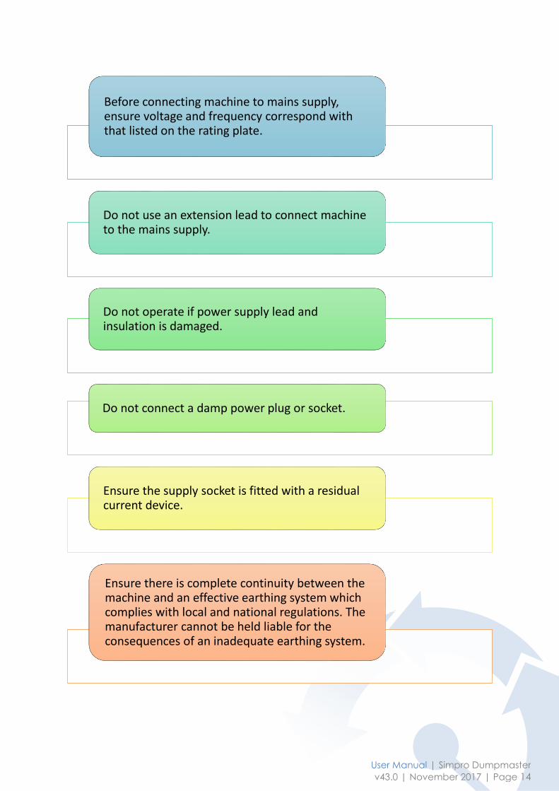
Before connecting machine to mains supply, ensure voltage and frequency correspond with that listed on the rating plate.
Do not use an extension lead to connect machine to the mains supply.
Do not operate if power supply lead and insulation is damaged.
Do not connect a damp power plug or socket.
Ensure the supply socket is fitted with a residual current device.
Ensure there is complete continuity between the machine and an effective earthing system which complies with local and national regulations. The manufacturer cannot be held liable for the consequences of an inadequate earthing system.
4 Operating Instructions
4.1 Before operation 1. Ensure machine is stable and on level ground, with a slope of 1:12 or less.
2. Ensure the that all covers and safety guards are in place.
3. Ensure the wheel brakes are applied and/or the feet are wound down onto the
ground (if the machine is fitted with castors).
4. Ensure that all personnel other than the operator are well clear of the machine.
5. Ensure the cradle is fully lowered.
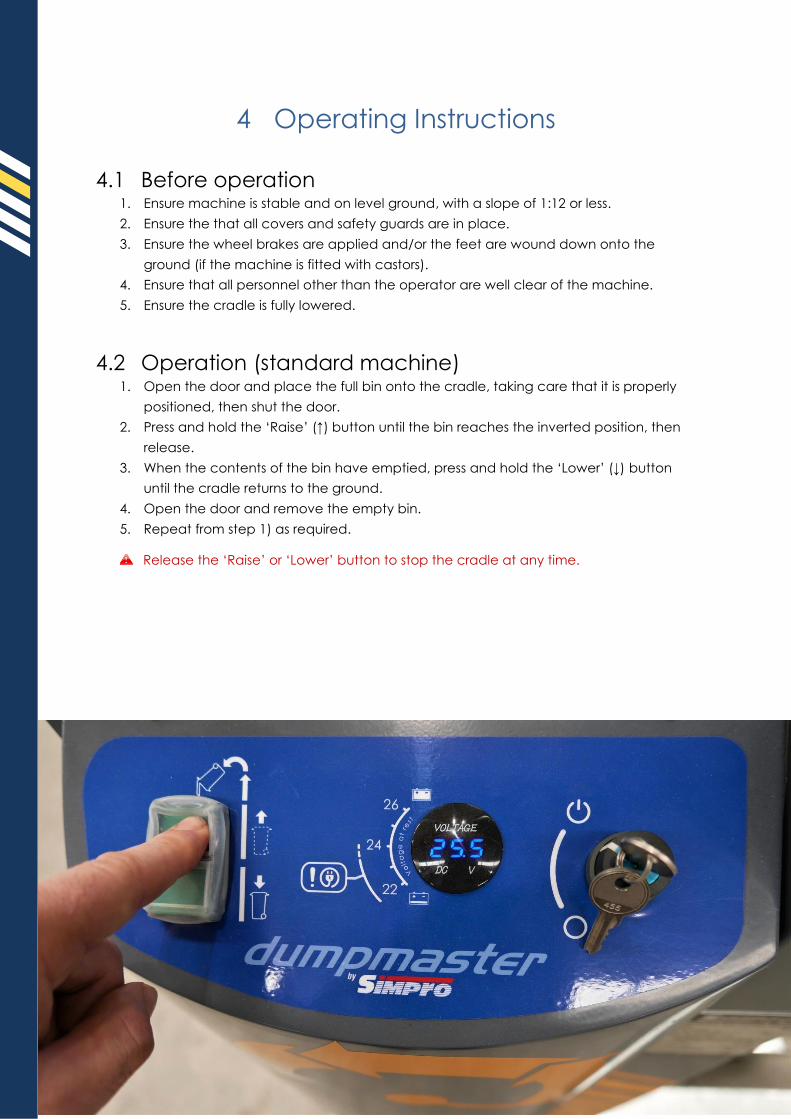
4.2 Operation (standard machine) 1. Open the door and place the full bin onto the cradle, taking care that it is properly
positioned, then shut the door.
2. Press and hold the ‘Raise’ (↑) button until the bin reaches the inverted position, then
release.
3. When the contents of the bin have emptied, press and hold the ‘Lower’ (↓) button
until the cradle returns to the ground.
4. Open the door and remove the empty bin.
5. Repeat from step 1) as required.
Release the ‘Raise’ or ‘Lower’ button to stop the cradle at any time.
User Manual | Simpro Dumpmaster
v43.0 | November 2017 | Page 16
4.3 Operation (autocycle machine) Some Dumpmaster models are fitted with an autocycle controller, which allows the operator
to move away while bins are being emptied. These machines may be used in either
‘Manual’ or ‘Automatic’ mode, selected using a switch on the control panel.
Machines fitted with an autocycle controller may be identified by the selector switch
on the control panel, labelled ‘MANUAL’ and ‘AUTO’.
An autocycle controller is included by default on all machines rated to safety
standards, such as ISO 13849-1 or AS/NZS 4024 Cat3/Cat4/PLd.
The operating procedure for each mode is as follows:
4.3.1 Automatic mode 1. Open the door. If the door is locked, turn the selector to ‘Manual’ mode and the door
will be unlocked for 20 seconds.
2. Place the full bin on the cradle, ensuring that it is properly positioned, and shut the
door.
3. Press and hold the ‘Reset’ button for two seconds.
4. With the selector in ‘Auto’ mode, press the ‘Raise’ (↑) button.
Press the ‘Emergency Stop’ button at any time to stop the cradle.
5. The cradle will lift then stop when it is fully tipped. After a short delay, the cradle will
come down and stop at ground level.
6. The door will be automatically unlocked for approximately 20 seconds. Open the
door and remove the empty bin.
7. Repeat from step 1) as required.
4.3.2 Manual mode 1. Open the door. If the door is locked, turn the selector to ‘Manual’ mode and the door
will be unlocked for 20 seconds.
2. Place the full bin on the cradle, ensuring that it is properly positioned, and shut the
door.
3. Press and hold the ‘Reset’ button for two seconds.
4. With the selector in ‘Manual’ mode, press and hold the ‘Raise’ (↑) button until the bin
reaches the inverted position, then release.
Release the ‘Raise’ button or press the ‘Emergency Stop’ button at any time to stop
the cradle.
5. When the contents of the bin have emptied, press and hold the ‘Lower’ (↓) button
until the cradle returns to the ground.
6. The door will be automatically unlocked for approximately 20 seconds. Open the
door and remove the empty bin.
7. Repeat from step 1) as required.
5 Maintenance Procedures
The Dumpmaster is designed to give many years of service with minimal maintenance. In the
event a fault or malfunction does occur, refer to the Quick Trouble Shooting Guide in Section
5.1 before contacting your agent for service. A Service Manual giving specific testing and
repair instructions is available on request from Simpro.
Contact your Simpro agent if repair or service work is required.
All repair and service work must be carried out by qualified authorized personnel.
Replacement parts must be supplied by Simpro or an authorized Simpro agent, and
must be of the same design and specification as the original parts.
Replacement hydraulic fluid must comply with specifications in Section 5.5.5.
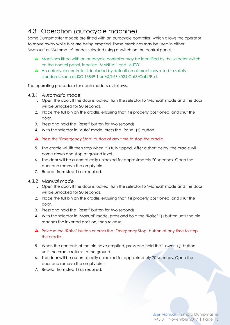
5.1 Quick Troubleshooting Guide Refer to the Quick Troubleshooting Guide below before contacting your agent for service.
A Service Manual with detailed testing and repair instructions is available on request.
Problem Possible Causes Remedy
The machine will not lift
bins, and the motor
does not run
Flat Battery Recharge the battery
Blown fuse, faulty
plug, or faulty
power lead
Check and rectify
Faulty switch or
wiring Check and rectify
Faulty raise relay or
contactor
The relay contactor should click when the
‘up’ button is pressed – if not, check and
replace
Motor running
wrong direction (3-
phase only)
Swap phase wires in plug
Interlock switch on
door not working
Contact your agent for details and / or
wiring diagrams
The machine will not lift
bins, although the
motor runs
Bin too heavy Reduce bin weight
Pressure-relief valve
set too low Contact your agent
Cradle will not come
down from the fully
raised position
Cradle sticking in
masts
Spray inside of masts at top of slots.
Smear grease on top of the curved
tipping tracks”.
Lubricate the roller arm at top of cradle
Lift ram jamming Contact your agent
Faulty switch, wiring,
or lowering valve
The lowering valve should click when the
button is pressed – if not, check the
switch, wiring and electro-magnetic coil
Cradle jams part way
down
Follower roller not
turning freely Lubricate the roller
Roller arm twisted or
cradle sitting out of
level
Check and straighten if necessary

User Manual | Simpro Dumpmaster
v43.0 | November 2017 | Page 18
5.2 Cleaning The Dumpmaster may be cleaned with a low-pressure water jet, a cloth and a mild cleaning
solution. Cleaning should be done with the cradle in the fully lowered position.
Do not clean the Dumpmaster with a high-pressure water jet, such as a water-blaster.
If the customer requires the cradle to be raised for cleaning, the control system may be
modified to allow this, while maintaining operator safety – contact your agent for details.
5.2.1 Ingress protection Item Ingress Protection
Push buttons IP66
Switches IP66
Lamps IP66
Door lock IP66
Coded magnetic switch IP66
Motor IP54 (additional protection provided by covers)
Overall IP55 (available options: IP56, IP69K)
5.3 Cradle jams Occasionally the bin cradle may become jammed at some point in the tipping cycle. This is
usually a minor issue which may be easily rectified.
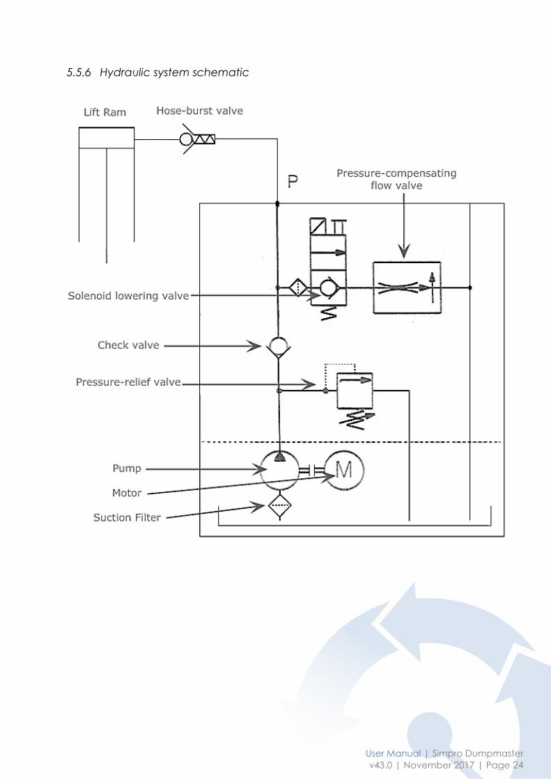
The cradle is not powered down – it is lowered by gravity alone.
All machines have a solenoid-operated lowering valve and a pressure-compensating
flow control valve.
Some machines also have a hose-burst valve on the ram port, and an external
manually-adjustable in-line flow control valve.
5.3.1 Cradle jams while raising If the cradle jams while raising the cause is almost always a mechanical fault.
1. Attempt to visually identify the cause or problem.
2. Lower the cradle to ground level if possible
3. Open the door, remove the bin, and rectify the problem.
If the bin is too heavy, or if the pressure-relief valve is set too low, the cradle may stop
part-way through the lifting cycle. Altering the setting in the relief valve must be done
only by a suitably qualified person, and authorisation must be obtained from Simpro.
5.3.2 Cradle jams while lowering If the cradle jams on the way down, or has jammed on the way up but will not come down, it
must be identified whether the jamming is due to a hydraulic, electrical, or mechanical
cause.
Hydraulic or electrical fault:
1. If the hose-burst valve has operated, the oil in the lift ram(s) cannot get out until
pressure on the ‘power-pack side’ of the valve exceeds the pressure in the rams:
a. If a hose or fitting has burst or come loose, correct this issue.
b. Raise the cradle slightly to reset the hose-burst valve.
c. The cradle will now lower normally.
2. If the lowering valve does not open (whether due to a hydraulic or electrical fault),
use the following procedure to lower the cradle to the ground:
a. Empty the bin if there is any product remaining in it.
b. Manually release the door lock as described in Section 5.7.1, and open the
door.
c. Attach lifting chains or slings to a hoist, and take the weight of the cradle.
Never place any part of your body underneath the cradle unless it is securely
supported.
d. Unscrew the fitting attaching the steel pipe to the power-pack, and hold the
end of the pipe over a container with a capacity of at least two litres.
e. Lower the cradle slowly, collecting the oil in the container. When fully lowered,
reconnect the pipe and fitting, and top up the oil tank.
f. Repair the fault, and return the cam to the Lock position.
Mechanical fault:
1. Empty the bin if there is any product remaining in it.
2. Manually release the door lock as described in Section 5.7.1, and open the door.
3. Provide support for the cradle, either with a structure underneath or with a sling
holding it to the top of the main frame. Allow for it to fall no more than 50mm.
Never place any part of your body underneath the cradle unless it is securely
supported.
4. Attempt to identify the cause of the jamming. The most likely causes are:
a. The lifting chain may have derailed from the plastic guide at the top of the
mast, on the side opposite the lift ram
b. A mast may have been bent or damaged, jamming one of the mast rollers
c. On machines with a single ‘tipping track’ in the middle, the top part of the
track may have been bent, interfering with the correct geometry of the
‘follower roller’.
d. Lack of lubrication on the follower roller, or the main cradle axle
e. The cradle may be sitting out of level, due to poor adjustment of the lifting
chains or to a breakage.
f. The ‘roller arm(s)’ may be pressing against the ‘tipping track’, due to the
cradle sitting out of level, or to the cradle not being centred between the
masts.
5. Once the problem has been identified, correct it and lower the cradle to the ground.
6. Run the machine through several full cycles with no load to ensure the problem has
been properly resolved. Then test with a full load.
7. If there are no further problems, the machine may be returned to service.

User Manual | Simpro Dumpmaster
v43.0 | November 2017 | Page 20
5.4 Battery and charger
If you do not operate a battery-powered Dumpmaster, please disregard this section.
Battery powered Dumpmasters are fitted with two high-quality lead-acid sealed gel batteries
and an automatic float charger. As a rule, a full charge is sufficient to empty up to 10 tonnes
of product, but this is dependent on the tipping height, and age and condition of the
battery.
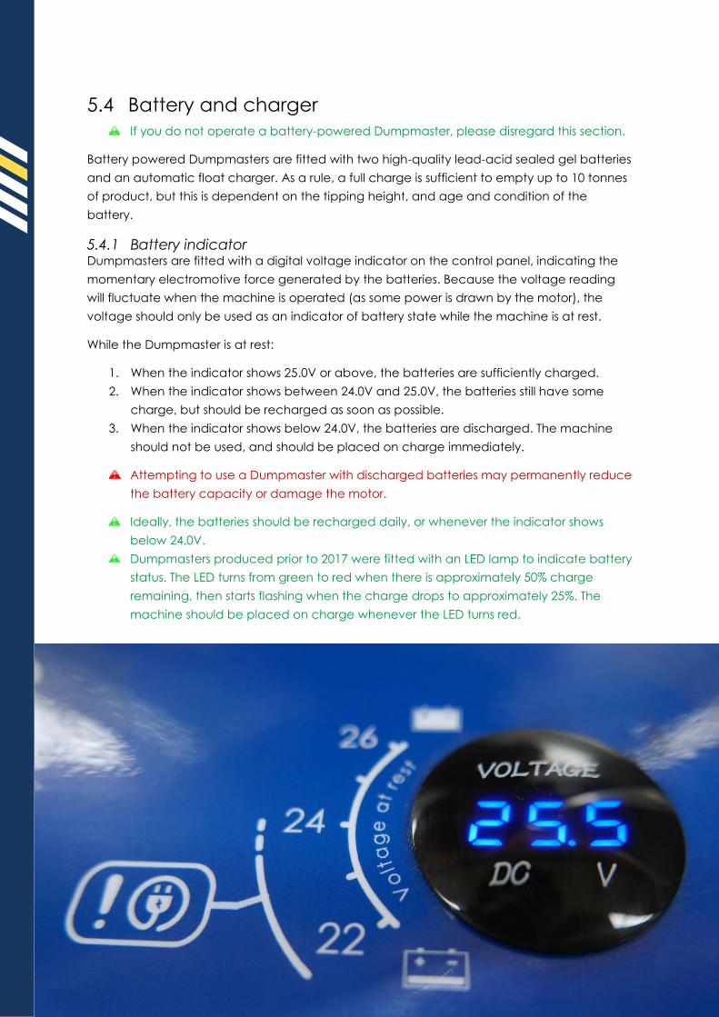
5.4.1 Battery indicator Dumpmasters are fitted with a digital voltage indicator on the control panel, indicating the
momentary electromotive force generated by the batteries. Because the voltage reading
will fluctuate when the machine is operated (as some power is drawn by the motor), the
voltage should only be used as an indicator of battery state while the machine is at rest.
While the Dumpmaster is at rest:
1. When the indicator shows 25.0V or above, the batteries are sufficiently charged.
2. When the indicator shows between 24.0V and 25.0V, the batteries still have some
charge, but should be recharged as soon as possible.
3. When the indicator shows below 24.0V, the batteries are discharged. The machine
should not be used, and should be placed on charge immediately.
Attempting to use a Dumpmaster with discharged batteries may permanently reduce
the battery capacity or damage the motor.
Ideally, the batteries should be recharged daily, or whenever the indicator shows
below 24.0V.
Dumpmasters produced prior to 2017 were fitted with an LED lamp to indicate battery
status. The LED turns from green to red when there is approximately 50% charge
remaining, then starts flashing when the charge drops to approximately 25%. The
machine should be placed on charge whenever the LED turns red.
User Manual | Simpro Dumpmaster
v43.0 | November 2017 | Page 22
5.4.2 Charging To recharge the batteries, simply plug an extension lead into a standard 1-phase 110v-240v
outlet, and into the appliance socket on the side of the Dumpmaster.
The onboard digital float charger automatically adapts to different supply voltages,
manages the charging cycle to maximise battery life and prevents overcharging.
A full recharge typically takes around 10 hours. The Dumpmaster may be used while on
charge.
If the Master Isolator switch is turned ‘Off’ the batteries will not charge.
The battery charger takes around three minutes to deliver enough power to empty a
200kg bin at 1800mm. This means that a battery-powered Dumpmaster can be
permanently plugged in, and used as though it were a 1-phase mains-powered
machine.
Dumpmasters produced prior to 2017 did not have an appliance socket, but used an
IEC power lead for charging. IEC power leads are commonly used for small
household appliances, and can be obtained from any general electronics store.
Dumpmasters produced prior to 2008 were supplied with lead-acid batteries, which
emit hydrogen gas while charging. Hydrogen ignites explosively in confined spaces,
so never allow naked flame, sparks or other ignition sources near the batteries. PVC
gauntlets and a face mask should be worn when checking the fluid level.
5.4.3 Maintenance High-quality deep-cycle sealed gel batteries require no regular maintenance and should last
up to five years.
Battery life is dependent on several factors, including the number of charge/discharge
cycles, the depth of discharge, and the age of the battery. In particular, using the
Dumpmaster while the battery voltage is below 24.0V will reduce the life of the batteries.
To obtain the maximum life, the batteries should be recharged daily, or whenever the
indicator shows below 24.0V.
5.4.4 Battery storage The sealed gel batteries have a two-year shelf life, and should be stored in accordance with
the following requirements:
1. Clean, dry and well-ventilated warehouse
2. Temperature of 5-40℃.
3. Upright orientation.
4. Out of direct sunshine, and away from heat sources.
5. No severe mechanical impacts, compression or distortion.
6. No contact with harmful substances, including metal filings, water and chemicals.
5.5 Hydraulic system
Spare parts are available from Simpro or any Simpro agent.
Refer to Section 5.5.6 for a schematic diagram of the hydraulic system.
5.5.1 Powerpack The hydraulic powerpack is supplied as a complete unit. The motor, pump, oil tank, and all
control valves are mounted into the centre manifold.
5.5.2 Control valves The hydraulic system has four primary control valves:
1. Check valve
2. Pressure-relief valve
3. Solenoid lowering valve
4. Pressure-compensating lowering-speed valve (this automatically regulates the
lowering speed, regardless of the load on the cradle).
5.5.3 Lift Rams The lift ram is a single-acting displacement type, very robust and reliable, but easy to
maintain should the need arise. A steel tube runs from the power-pack to the lift ram. A Hose-
burst valve is fitted directly to one (or both) ram ports.
5.5.4 Maintenance As the pump only runs while the cradle is lifting, it can take at least 500 bins to reach 1 hours’
run time of the power-pack. The oil should be replaced, and the suction filter cleaned after
12 months, then after every 100 hours of run time. The lowering valve should also be removed
and cleaned at this time.
5.5.5 Hydraulic fluid Any good-quality mineral oil-based hydraulic fluid suitable for hydraulic systems can be used.
The fluid should have physical lubricating and chemical properties as specified by:
1. Mineral Oil Based Hydraulic Fluids HL (DIN 51524 part 1)
2. Mineral Oil Based Hydraulic Fluids HL P (DIN 51524 part 2)
User Manual | Simpro Dumpmaster
v43.0 | November 2017 | Page 24
5.5.6 Hydraulic system schematic
5.6 Safety Door
5.6.1 Side-hinge door The standard Dumpmaster is fitted with a side-hinge safety door, consisting of a steel tube
frame with 25x25x2mm wire mesh guarding. This door is very simple and robust, but will
benefit from occasional servicing as follows:
1. Lightly lubricate the door pivot points with silicone spray.
2. Check the door safety interlock to ensure it works as intended, as follows:
a. Firstly, raise the cradle a little off the ground and try to open the door. If it can
open, the switch operated by the cradle may need adjusting or replacing.
Contact the agent or manufacturer for instructions.
b. Next, open the door then press the Raise and Lower buttons and make sure
the machine does not run. If it does, contact the agent or manufacturer for
instructions.
3. Check that all fixings are tight.
5.6.2 Lift-up door Some custom Dumpmaster are fitted with a single lift-up door. This type of door is supported
by gas struts and takes up a minimum of space, but has several moving parts and will benefit
from occasional servicing as follows:
1. The arm pivot points should be lubricated occasionally (both ends of all four arms).
2. Check the door safety interlock to ensure it works as intended, as follows:
a. Firstly, raise the cradle a little off the ground and try to open the door. If it can
open, the switch operated by the cradle may need adjusting or replacing.
Contact the agent or manufacturer for instructions.
b. Next, open the door then press the Raise and Lower buttons and make sure
the machine does not run. If it does, contact the agent or manufacturer for
instructions.
3. Ensure the retainer caps on the arm pivot bars are in place, and that all fixings are
tight.
4. The gas struts are designed to balance the weight of the door throughout its travel,
and hold it open. Over time, the gas in the struts can leak out, resulting in reduced
lifting force. If the struts do not hold the door open, one or both may need to be
replaced.
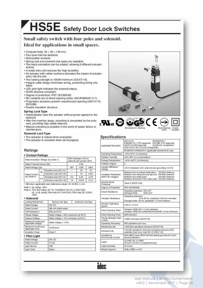
5.7 Safety Door Interlock The Dumpmaster is fitted with either one or two solenoid-operated safety door interlocks.
From 2016, the interlocks are Idec model HS5E-D4403-G or HS5E-F4403-G. These are ‘power-
to-unlock’ type, with four internal contacts which are used to determine whether the door is
closed and locked.
A full copy of the user manual for the Idec door lock may be downloaded from this link.
A summary of the specifications is included on the following page.
User Manual | Simpro Dumpmaster
v43.0 | November 2017 | Page 26

5.7.1 Manual override If required, the safety door interlock can be manually disabled by the following procedure.
1. Insert the yellow Manual Unlocking
Key into the triangular cam on the
lock.
2. Turn key fully to the Unlock position.
3. The control system goes into Safe
Mode as soon as a lock is manually
unlocked, and cannot be reset until returned to the Lock position.
4. If any work must be done on the cradle, or if it should be raised off the ground for
cleaning, it must be set in position before the door lock is manually unlocked, as it
cannot be moved once it is unlocked.
Do not use the safety switch with the key not fully turned (less than 90°) as this may
cause damage to the switch or operation failures (when manually unlocked, the
switch will keep the main circuit disconnected and the door unlocked).
Do not apply excessive force to the manual unlock components, otherwise the
manual unlock part will become damaged.
Never leave the manual unlocking key attached to the switch during operation. This is
dangerous because the switch can always be unlocked while the machine is in
operation.
5.8 Raised-cradle maintenance All maintenance work on the Dumpmaster should be conducted with the cradle in the
lowered position. If the cradle needs to be raised during maintenance, or if the door needs
to be opened while the cradle is raised above ground level, observe the following
procedures:
This work should only be carried out by a suitably qualified, authorised technician.
1. Turn the main isolator switch to ‘Off’.
2. Manually disable the safety door interlock as described in Section 5.7.1.
3. The door can now be opened even if the cradle is not fully lowered. The control
system will automatically enter ‘Safe Mode’, which means the cradle cannot be
raised or lowered unless the door is shut and the system is reset.
4. When finished, turn the safety door interlock cam back to the ‘Lock’ position.
5. Reset the system, and test the machine and safety functions before returning to
service.
User Manual | Simpro Dumpmaster
v43.0 | November 2017 | Page 28
6 Handling, transportation and storage
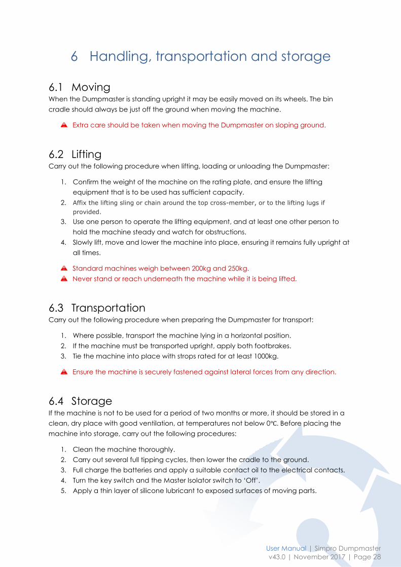
6.1 Moving When the Dumpmaster is standing upright it may be easily moved on its wheels. The bin
cradle should always be just off the ground when moving the machine.
Extra care should be taken when moving the Dumpmaster on sloping ground.
6.2 Lifting Carry out the following procedure when lifting, loading or unloading the Dumpmaster:
1. Confirm the weight of the machine on the rating plate, and ensure the lifting
equipment that is to be used has sufficient capacity.
2. Affix the lifting sling or chain around the top cross-member, or to the lifting lugs if
provided.
3. Use one person to operate the lifting equipment, and at least one other person to
hold the machine steady and watch for obstructions.
4. Slowly lift, move and lower the machine into place, ensuring it remains fully upright at
all times.
Standard machines weigh between 200kg and 250kg.
Never stand or reach underneath the machine while it is being lifted.
6.3 Transportation Carry out the following procedure when preparing the Dumpmaster for transport:
1. Where possible, transport the machine lying in a horizontal position.
2. If the machine must be transported upright, apply both footbrakes.
3. Tie the machine into place with strops rated for at least 1000kg.
Ensure the machine is securely fastened against lateral forces from any direction.
6.4 Storage If the machine is not to be used for a period of two months or more, it should be stored in a
clean, dry place with good ventilation, at temperatures not below 0℃. Before placing the
machine into storage, carry out the following procedures:
1. Clean the machine thoroughly.
2. Carry out several full tipping cycles, then lower the cradle to the ground.
3. Full charge the batteries and apply a suitable contact oil to the electrical contacts.
4. Turn the key switch and the Master Isolator switch to ‘Off’.
5. Apply a thin layer of silicone lubricant to exposed surfaces of moving parts.

7 Safety Monitoring System
If you do not operate a machine rated to safety standards such as ISO 13849-1 or
AS/NZS 4024 Cat3/Cat4/PLd, please disregard this section.
7.1 Overview Machines with a safety rating of Cat3 or higher are fitted with a Rockwell CR-30 Safety Relay
to monitor the safety systems. The CR30 Safety Relay continuously monitors the status of the
Emergency Stop contacts, door lock, ‘cradle-lowered sensor’, and ‘tipper in position sensor’
(if fitted).
The Safety Relay goes into ‘Safe Mode’:
1. If any fault is detected;
2. Whenever the door is unlocked/opened;
3. Whenever the Emergency Stop is pressed;
4. Whenever the tipper is moved away from the ‘safe’ position (optional).
Whenever the machine is in Safe Mode the blue Reset lamp glows, and the machine must
be reset before it can be used to empty a bin. To reset, ensure the door is correctly closed
and locked, the Emergency Stop is released, and the tipper is in the Safe position, then press
and hold the Reset button for 1 - 2 seconds, then release it (the lamp will go out). If any of the
safety functions above are not correct, or if a fault has been detected in any of the
equipment or connections, the system will not reset.
This documentation is to assist an engineer or electrician to find and repair any fault
preventing the system from resetting. Most faults can be traced from the LEDs on the CR30
safety relay itself; some locks and sensors also have LEDs to assist in trouble-shooting.
7.2 440C-CR30 Safety relay The 440C-CR30-22BBB (CR30) relay is a software-configurable safety relay. This device is
intended to be part of the safety-related control system of a machine. The CR30 safety relay
is based on the Micro800 platform and must
be configured using a personal computer (PC)
with the Allen-Bradley® Connected
Components Workbench software.
The housing is red to signify it as a safety
device and to distinguish it from the grey-
coloured standard controllers.
The CR30 safety relay accommodates up to
24 safety monitoring functions. Examples of
safety monitoring functions are single channel
input, dual channel input, two hand control,
reset, and feedback. It has 22 embedded

User Manual | Simpro Dumpmaster
v43.0 | November 2017 | Page 30
safety rated inputs and outputs and accepts up to two plug-in modules, each of which has
four standard inputs and four standard outputs.
The CR30 safety relay can be configured to accept two single-wire safety inputs and to
provide two single-wire safety outputs. This feature allows the CR30 safety relay to be an
integral part of an extensive machine safeguarding system.
There are 10 Input LED’s, 5 General Status LED’s, and 6 Output LED’s. These can help identify
faults and do basic trouble-shooting. The input and output LED’s are set up when designing
the program. A print-out of the program function and what each LED refers to should be
provided with each machine.
The ‘PWR’ and ‘RUN’ LED’s should be on when the system is ready for use. If the ‘FAULT’ or
‘LOCK’ LED’s are showing, try cycling the power. If they remain on, a computer with
‘Connected Components Workbench software installed must be connected to identify and
resolve the problem.
7.2.1 Troubleshooting Faults in the CR30 relay fall into two categories: recoverable faults, and non-recoverable
faults. Non-recoverable faults require power cycling to recover after the fault is corrected.
Recoverable faults can be cleared by eliminating the cause of the fault and cycling the
inputs associated with the fault. The output that is connected to an input with that fault is
switched off. The other outputs, which are not affected by the fault, will continue to work.
Examples of recoverable faults include:
- SMF Faults
- Cross loop
- Simultaneity Faults
- Reset button fault
- Muting: Synchronization time exceed
- Muting time exceeded
- Sequence fault
7.2.2 Configuration The CR30 is software configurable using the Rockwell Automation ‘Connected Components
Workbench’ (CCW) software. Connected Components Workbench is a set of collaborative
tools supporting the CR30 safety relays. The CCW is used to configure the CR30, program the
Micro 800 controllers, and configure many PowerFlex drives and PanelView graphic display
terminals.
The CCW software is free and can be downloaded from this link. To help you configure your
relay through the Connected Components Workbench software, you can refer to the
Connected Components Workbench Online Help (provided with the software).
The CR30 has a USB interface for connection to a
personal computer for configuration. Use a
standard USB A Male to B Male cable for
connecting to the relay.
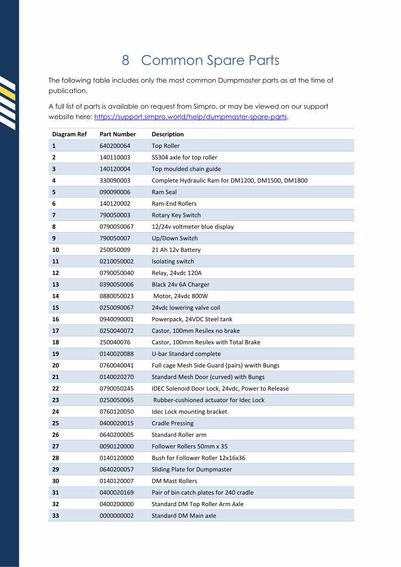
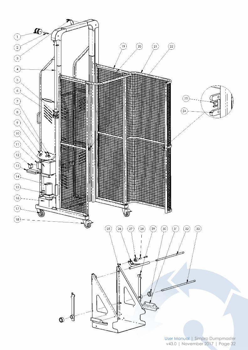
8 Common Spare Parts
The following table includes only the most common Dumpmaster parts as at the time of
publication.
A full list of parts is available on request from Simpro, or may be viewed on our support
website here: https://support.simpro.world/help/dumpmaster-spare-parts.
Diagram Ref Part Number Description
1 640200064 Top Roller
2 140110003 SS304 axle for top roller
3 140120004 Top moulded chain guide
4 330090003 Complete Hydraulic Ram for DM1200, DM1500, DM1800
5 090090006 Ram Seal
6 140120002 Ram-End Rollers
7 790050003 Rotary Key Switch
8 0790050067 12/24v voltmeter blue display
9 790050007 Up/Down Switch
10 250050009 21 Ah 12v Battery
11 0210050002 Isolating switch
12 0790050040 Relay, 24vdc 120A
13 0390050006 Black 24v 6A Charger
14 0880050023 Motor, 24vdc 800W
15 0250090067 24vdc lowering valve coil
16 0940090001 Powerpack, 24VDC Steel tank
17 0250040072 Castor, 100mm Resilex no brake
18 250040076 Castor, 100mm Resilex with Total Brake
19 0140020088 U-bar Standard complete
20 0760040041 Full cage Mesh Side Guard (pairs) wwith Bungs
21 0140020270 Standard Mesh Door (curved) with Bungs
22 0790050245 IDEC Solenoid Door Lock, 24vdc, Power to Release
23 0250050065 Rubber-cushioned actuator for Idec Lock
24 0760120050 Idec Lock mounting bracket
25 0400020015 Cradle Pressing
26 0640200005 Standard Roller arm
27 0090120000 Follower Rollers 50mm x 35
28 0140120000 Bush for Follower Roller 12x16x36
29 0640200057 Sliding Plate for Dumpmaster
30 0140120007 DM Mast Rollers
31 0400020169 Pair of bin catch plates for 240 cradle
32 0400200000 Standard DM Top Roller Arm Axle
33 0000000002 Standard DM Main axle
User Manual | Simpro Dumpmaster
v43.0 | November 2017 | Page 32
9 Warranty
9.1 Definitions:
1. “Simpro” means Simpro Handling Equipment Limited, New Zealand Registered Company No.
1827916.
2. “Agent” means a person or company authorized by Simpro to sell a Product.
3. “Service Agent” means a person or company authorized by Simpro to repair a Product.
4. “End User” means the first purchaser of a Product from a Sales Agent authorised by Simpro to sell the
Product.
5. “Warranty” means the commitment that Simpro has to guarantee the workmanship and
componentry to any End User of Products manufactured and sold by Simpro.
6. “Warranty Claim” means an application from an Agent to Simpro to be reimbursed for expenses
relating to repairs done to remedy a fault with a Simpro Product.
7. “Warranty Period” means the length of time that Simpro undertakes to guarantee a Product.
8. “Back to Base” means that the costs associated with the transporting of a Product between the
Service Agent and the End User is the End Users responsibility.
9. “Standard Products” means any Product displayed as a standard product on the Simpro website,
https://simpro.world/.
10. “Part” and “Parts” refer to components of a Product.
11. “Minor Fault” means a fault or defect that requires less than one hour to rectify
12. “Instruction Handbook” means a document so titled that provides brief information and guidance
on the operation of the Product for commonly performed functions.
13. “Service Manual” means a document so titled that provides comprehensive information and
guidance for service, repairs and maintenance.
14. “Warranty Registration Process” means the process of an End User registering their product with
Simpro. This may be done using the web form here: https://simpro.world/support/warranty-
registration
15. “Application for Warranty Consideration Form” means the system used to file a Warranty Claim with
Simpro. This may be done using the web form here: https://simpro.world/support/warranty-claim.
9.2 Coverage
1. Simpro provides a 12 month Back to Base Warranty on all Standard Products unless alternative terms
have been agreed to in writing.
2. The Warranty terms and conditions on custom-built and non-standard machines are generally
specified on quotations, and placing an order implies acceptance of the Warranty terms. If no
specific Warranty details have been provided, the standard terms and conditions will apply.
3. The 12-month Warranty period shall be taken from the date the machine first leaves the Agent’s
premises, whether sold or just supplied for trial. The Agent shall keep accurate records of the date of
all machine trials, sales. etc.
4. Simpro will, at its option, repair or replace any items that fail or prove defective within the Warranty
period.
5. Simpro’s liability under the terms of this Warranty shall be limited to remedying any fault that occurs
on machines it has manufactured or supplied, and shall not cover any consequential loss or
damage.
6. The Warranty on batteries is for 6 months only. Information on maximising the life of your batteries
may be viewed here: https://simpro.world/connect/blog/deep-cycle-batteries-watts-it-all-about
9.3 Exclusions
1. Simpro will not recognise a Warranty Claim against a machine where payment to Simpro for that
machine is outstanding. If a Warranty Claim is made before payment is due, the full payment must
be made on the due date. The Warranty Claim, if accepted, will be credited at a later date.
2. Warranty Claims may not be recognized unless the Warranty Registration Process has been
completed. If not done at the time of sale, this should be done at the time of the Warranty Claim. If
warranty registration has not been completed, proof of purchase may be required.
User Manual | Simpro Dumpmaster
v43.0 | November 2017 | Page 34
3. Damage caused or contributed to by misuse, abuse, accident, unauthorised repairs or
modifications, or failure to use the machine in accordance with instructions is specifically excluded.
4. Travelling time and mileage are specifically excluded from the Simpro warranty coverage. However
under certain circumstances Simpro at its discretion may contribute to these costs. Authorisation
must be obtained from Simpro prior to any such Warranty Claim. This does not prohibit an Agent
offering more extensive Warranty cover, outside of this Warranty, as negotiated between the Agent
and the End User.
9.4 End User Claim Procedure
1. Where a fault or breakdown appears to have occurred the End User should, if applicable, first
consult the Quick Troubleshooting Guide section of the User Manual provided with each machine, to
ascertain the cause of the fault and remedy if possible. This information may also be accessed on
the Simpro Support website: http://support.simpro.world.
2. If the fault is not able to be remedied, the End User should contact the Agent who sold the machine,
and explain as fully as possible the fault, including all relevant factors such as:-
1. Did the fault occur suddenly or has it been giving trouble over some time?
2. Was the machine being used at the time?
3. Is the fault intermittent?
4. Are the batteries fully charged?
5. If repair is urgent, and the Agent cannot be contacted, the End User may contact Simpro
direct.
9.5 Agent Claim Handling Procedure
1. Upon receiving notification of a fault, the Service Agent should attempt to determine the cause and
a course of action before going to see the machine.
2. The Service Agent should contact Simpro for assistance in identifying the fault, if it is not apparent.
This step is important, so that if a site visit is necessary, the correct tools and spare Parts can be taken.
It is also important to establish whether there may have been any negligence, misuse or an accident
that contributed to or caused the fault.
3. Parts requiring replacement will be supplied by Simpro free of charge; in some cases, it may be
necessary to source Parts locally if needed urgently, but Simpro must authorize this if the cost of the
item exceeds $50.00 and is to be charged to Simpro.
4. If the fault is not a Minor Fault, the Agent must notify Simpro and receive authorization to proceed
before the repair work is done. Simpro will assist in every way possible, including discussing the
problem directly with the End User if necessary to determine the best method of effecting the repair,
in the shortest time possible.
5. Upon completion of the repair to an acceptable standard, the Agent shall complete the
Application For Warranty Consideration Form and include copies of any invoices for labour, and any
Parts supplied.
6. The cost of Warranty repairs is not to be deducted from any payments due to Simpro, unless Simpro
issues a credit note clearly stating the amount and which invoice it relates to.
7. Simpro undertakes to be reasonable in respect of all Warranty repairs undertaken by Agents, but
reserves the right to decline payment for:-
1. Work done or materials replaced that were not authorized in advance by Simpro.
2. Work not done to an acceptable standard.
3. Work taking an unduly long time, due (in part or in full) to the lack of knowledge or skill of
the serviceman or the Agent. The time allowed for repair work will be based on Simpro’s
assessment of what a reasonably skilled tradesman would take. Full Service Manuals are
available on request at any time from Simpro and all service visits should be conducted with
a Service Manual at hand.
6. dealer who supplied the machine. No claims will be recognised unless authorisation is obtained from
the manufacturer before any repairs are done.
This warranty shall be interpreted according to the laws of New Zealand and the parties agree to submit to
the jurisdiction of the Courts of New Zealand.
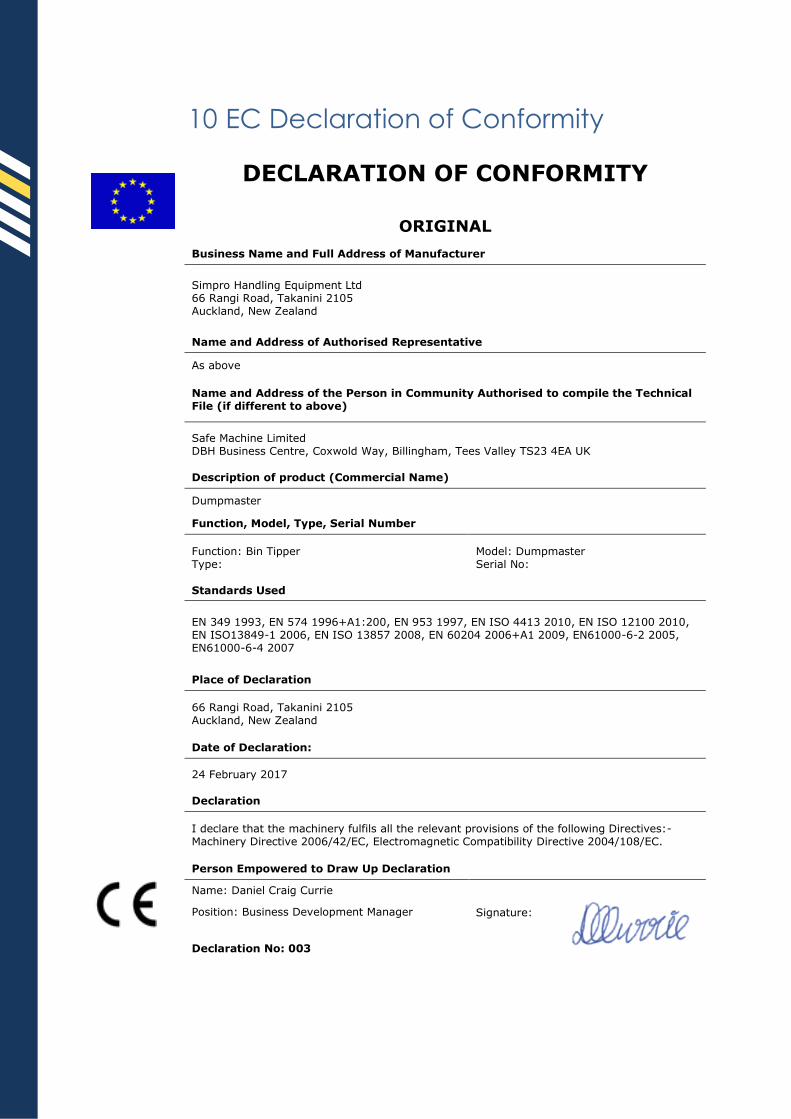
10 EC Declaration of Conformity
DECLARATION OF CONFORMITY
ORIGINAL
Business Name and Full Address of Manufacturer
Simpro Handling Equipment Ltd 66 Rangi Road, Takanini 2105 Auckland, New Zealand
Name and Address of Authorised Representative
As above
Name and Address of the Person in Community Authorised to compile the Technical File (if different to above)
Safe Machine Limited DBH Business Centre, Coxwold Way, Billingham, Tees Valley TS23 4EA UK
Description of product (Commercial Name)
Dumpmaster
Function, Model, Type, Serial Number
Function: Bin Tipper Type:
Model: Dumpmaster Serial No:
Standards Used
EN 349 1993, EN 574 1996+A1:200, EN 953 1997, EN ISO 4413 2010, EN ISO 12100 2010, EN ISO13849-1 2006, EN ISO 13857 2008, EN 60204 2006+A1 2009, EN61000-6-2 2005, EN61000-6-4 2007
Place of Declaration
66 Rangi Road, Takanini 2105 Auckland, New Zealand
Date of Declaration:
24 February 2017
Declaration
I declare that the machinery fulfils all the relevant provisions of the following Directives:- Machinery Directive 2006/42/EC, Electromagnetic Compatibility Directive 2004/108/EC.
Person Empowered to Draw Up Declaration
Name: Daniel Craig Currie
Signature: Position: Business Development Manager
Declaration No: 003

User Manual | Simpro Dumpmaster
v43.0 | November 2017 | Page 36
11 Scheduled Inspections
It is recommended to conduct regular scheduled inspections of the Dumpmaster. This helps
to ensure operator safety and extend the service life of the machine.
The inspection schedule is divided into three parts: weekly, monthly and annual inspections.
The inspection procedures are described in the following pages, along with tables to record
the results.
It is strongly recommended that that regular scheduled inspections be carried and
recorded as described in this section.
Operators should immediately stop using the machine and request an inspection if
any fault or abnormal operation is observed.
11.1 Preinspection checklist 1. Wear suitable Personal Protective Equipment, including safety boots and protective
eyewear.
2. Ensure there are no ignition sources nearby.
3. Lower the cradle and remove bin.
4. Turn off the key switch and unplug the charging lead.
5. Remove the powerpack cover.
6. Clean the powerpack and electric circuitry with compressed air. Never use water or
chemicals.
7. Always use height safety equipment when servicing elevated areas such as the top
of the mast.
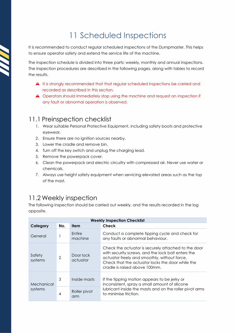
11.2 Weekly inspection The following inspection should be carried out weekly, and the results recorded in the log
opposite.
Weekly Inspection Checklist
Category No. Item Check
General 1 Entire
machine
Conduct a complete tipping cycle and check for
any faults or abnormal behaviour.
Safety
systems 2
Door lock
actuator
Check the actuator is securely attached to the door
with security screws, and the lock bolt enters the
actuator freely and smoothly, without force.
Check that the actuator locks the door while the
cradle is raised above 100mm.
Mechanical
systems
3 Inside masts If the tipping motion appears to be jerky or
inconsistent, spray a small amount of silicone
lubricant inside the masts and on the roller pivot arms
to minimise friction. 4 Roller pivot
arm

User Manual | Simpro Dumpmaster
v43.0 | November 2017 | Page 38
Date Service
Person Location
Checks
complete
Notes on repairs or
maintenance required
Parts and
materials used
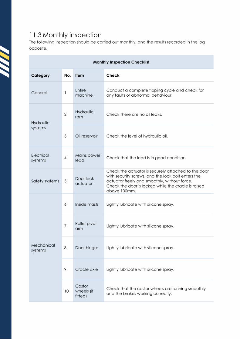
11.3 Monthly inspection The following inspection should be carried out monthly, and the results recorded in the log
opposite.
Monthly Inspection Checklist
Category No. Item Check
General 1 Entire
machine
Conduct a complete tipping cycle and check for
any faults or abnormal behaviour.
Hydraulic
systems
2 Hydraulic
ram Check there are no oil leaks.
3 Oil reservoir Check the level of hydraulic oil.
Electrical
systems 4
Mains power
lead Check that the lead is in good condition.
Safety systems 5 Door lock
actuator
Check the actuator is securely attached to the door
with security screws, and the lock bolt enters the
actuator freely and smoothly, without force.
Check the door is locked while the cradle is raised
above 100mm.
Mechanical
systems
6 Inside masts Lightly lubricate with silicone spray.
7 Roller pivot
arm Lightly lubricate with silicone spray.
8 Door hinges Lightly lubricate with silicone spray.
9 Cradle axle Lightly lubricate with silicone spray.
10
Castor
wheels (if
fitted)
Check that the castor wheels are running smoothly
and the brakes working correctly.

User Manual | Simpro Dumpmaster
v43.0 | November 2017 | Page 40
Date Service
Person Location
Checks
complete
Notes on repairs or
maintenance required
Parts and
materials used
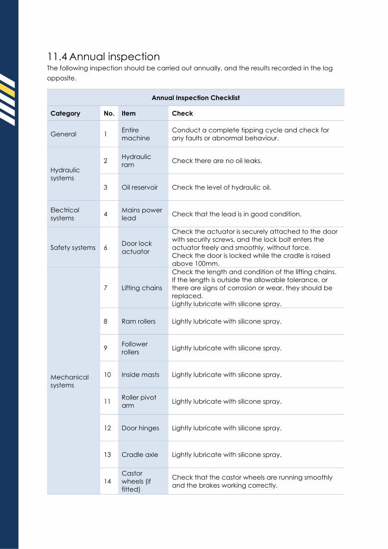
11.4 Annual inspection The following inspection should be carried out annually, and the results recorded in the log
opposite.
Annual Inspection Checklist
Category No. Item Check
General 1 Entire
machine
Conduct a complete tipping cycle and check for
any faults or abnormal behaviour.
Hydraulic
systems
2 Hydraulic
ram Check there are no oil leaks.
3 Oil reservoir Check the level of hydraulic oil.
Electrical
systems 4
Mains power
lead Check that the lead is in good condition.
Safety systems 6 Door lock
actuator
Check the actuator is securely attached to the door
with security screws, and the lock bolt enters the
actuator freely and smoothly, without force.
Check the door is locked while the cradle is raised
above 100mm.
Mechanical
systems
7 Lifting chains
Check the length and condition of the lifting chains.
If the length is outside the allowable tolerance, or
there are signs of corrosion or wear, they should be
replaced.
Lightly lubricate with silicone spray.
8 Ram rollers Lightly lubricate with silicone spray.
9 Follower
rollers Lightly lubricate with silicone spray.
10 Inside masts Lightly lubricate with silicone spray.
11 Roller pivot
arm Lightly lubricate with silicone spray.
12 Door hinges Lightly lubricate with silicone spray.
13 Cradle axle Lightly lubricate with silicone spray.
14
Castor
wheels (if
fitted)
Check that the castor wheels are running smoothly
and the brakes working correctly.
User Manual | Simpro Dumpmaster
v43.0 | November 2017 | Page 42
Date Service
Person Location
Checks
complete
Notes on repairs or
maintenance required
Parts and
materials used
S impro Handl ing Equipment Ltd
66 Rangi Road, Takanini 2105
Auckland, New Zealand
emai l [email protected]
web http://s impro.world
phone +64 9 634 7445
au f ree 1800 25 00 59
nz free 0800 734 744
usa 323 977 2857
uk 1603 389 049