user manual - rfi storage/byd/b... · byd company limited tel: 0755-8988 8888 ... 3 technical...
TRANSCRIPT

B-Box user manual
User Manual
B-Box 2.5~10.0
20161026
Version: 2.1
Copyright © BYD Company Limited. All rights reversed.
Non-written consent of BYD company, any unit or individual shall not extract, copy contents of the
document, it is not allowed to translate in any.

B-Box user manual
Statement:
As the product version update or other reasons, this document will be subject to change with
notice. Unless otherwise agreed, the document used as guidance only, all statements in this
document, information and suggestions do not constitute any express or implied.
Please kindly contact us for more information.
BYD Company Limited
TEL: 0755-8988 8888
FAX: 0755-8961 9653

Page 3
CONTENT
1 INFORMATION IN THIS MANUAL........................................................................................................... 5
1.1 ABOUT THIS MANUAL ................................................................................................................................. 5
1.2 TARGET GROUP ......................................................................................................................................... 5
1.3 INTEND USAGE .......................................................................................................................................... 5
1.4 B-BOX&B-PLUS DEFINITION ....................................................................................................................... 5
1.5 IDENTIFYING THE PRODUCT ......................................................................................................................... 5
2 SAFETY .................................................................................................................................................. 6
2.1 SAFETY PRECAUTION .................................................................................................................................. 6
2.2 SAFETY GUIDELINES FOR INSTALLATION .......................................................................................................... 7
3 TECHNICAL PARAMETERS ...................................................................................................................... 8
4 TECHNICAL NOUN EXPLANATION .......................................................................................................... 9
5 PRODUCT OVERVIEW .......................................................................................................................... 10
5.1 B-BOX SYSTEM BRIEF INTRODUCTION ......................................................................................................... 10
5.2 B-BOX CONFIGURATION TABLE .................................................................................................................. 11
5.3 B-BOX SYSTEM DIAGRAM ......................................................................................................................... 12
5.4 GENERAL INTRODUCTION OF BMU ............................................................................................................. 12
5.5 GENERAL INTRODUCTION OF B-PLUS 2.5 ..................................................................................................... 13
5.5.1 B-Plus 2.5 brief introduction ........................................................................................................ 13
5.6 BATTERY TECHNICAL PARAMETERS............................................................................................................... 14
5.7 B-PLUS 2.5 ADDRESS SWITCH INTRODUCTION ............................................................................................... 16
6 START SYSTEM .................................................................................................................................... 16
6.1 SYSTEM ACTIVITY PROCEDURES WHEN B-BOX CONNECT TO SMA SUNNY ISLAND ................................................ 16
6.2 SYSTEM ACTIVITY PROCEDURES WHEN B-BOX CONNECT TO GOODWE INVERTER. .............................................. 18
6.3 SYSTEM ACTIVITY PROCEDURES WHEN B-BOX CONNECT TO SOLAX INVERTER ...................................................... 19
7 STOPPING THE SYSTEM ....................................................................................................................... 20
7.1 STOPPING THE SYSTEM WHEN B-BOX WORKING WITH SMA SUNNY ISLAND ................................................... 20
7.2 STOPPING THE SYSTEM WHEN B-BOX WORKING WITH GOODWE INVERTER ...................................................... 21
7.3 STOPPING THE SYSTEM WHEN B-BOX WORKING WITH SOLAX INVERTER ............................................................. 21
8 CLEANING AND MAINTENANCE ........................................................................................................... 22
8.1 CLEANING .............................................................................................................................................. 22
8.2 MAINTENANCE ........................................................................................................................................ 22
9 DISPOSE SPECIAL SITUATION............................................................................................................... 22
9.1 BATTERY OVER DISCHARGED MAINTENANCE .................................................................................................. 22

Page 4
9.2 CATASTROPHIC ACCIDENTS ........................................................................................................................ 22
10 BOX CONFIGURATION LIST WITH DIFFERENT INVERTER ................................................................... 23
10.1 B-BOX CONFIGURATION LIST WITH SMA SUNNY ISLAND ............................................................................... 23
10.2 B-BOX CONFIGURATION LIST WITH GOODWE ES INVERTER ......................................................................... 24
10.3 B-BOX CONFIGURATION LIST WITH GOODWE BP INVERTER ........................................................................ 24
10.4 B-BOX CONFIGURATION LIST WITH SOLAX INVERTER .................................................................................... 24
11 NORMAL ISSUES AND SOLUTIONS ..................................................................................................... 25
11.1 NORMAL ALARM AND SOLUTION DISPLAY ON SMA SUNNY ISLAND SRC............................................................ 25
11.2 NORMAL ALARM AND SOLUTION DISPLAY ON B-PLUS 2.5 .............................................................................. 26
12 WARRANTY ....................................................................................................................................... 27
13 LOGIN IN AFTER SERVICE WEB........................................................................................................... 27
14 CONTACT ........................................................................................................................................... 27
APPENDIX 1 : BATTERY ADDRESS SETTING LIST ...................................................................................... 28
APPENDIX 2 : BATTERY PARAMETER SETTING TABLE ............................................................................. 29

Page 5
1 INFORMATION IN THIS MANUAL
1.1 About this manual
This user manual introduces the B-Box product information, using guidance, safety caution items and normal
failure and actions can be done by user. When using the B-BOX, if had any abnormal failure or urgent occurs,
please contact with the after service center.
1.2 Target Group
This user manual applies for the B-BOX 2.5, B-BOX 5.0, B-BOX 7.5, B-BOX 10.0.
1.3 Intend usage
The B-BOX can be used in household energy storage application ,includes on/off grid system. When B-BOX
works with different inverter, user should refer to the configuration list with different inverters which are
suggested by BYD.
1.4 B-BOX&B-Plus definition
BYD battery box products- B-Box2.5~B-Box10.0 are defined as below:
B-Box: Battery Box
B-Plus2.5: battery unit with nominal capacity is 2.56Kwh, Will be installed inside the cabinet as an energy
storage module.
B-Box2.5: Battery nominal capacity is 2.56 Kwh (Includes 1pcs B-Plus 2.5)
B-Box 5.0: Battery nominal capacity is 5.12 Kwh (Includes 2pcs of B-Plus 2.5)
B-Box 7.5: Battery nominal capacity is 7.68 Kwh (Includes 3pcs of B-Plus 2.5)
B-Box 10.0: Battery nominal capacity is 10.24 Kwh (Includes 4pcs of B-Plus 2.5)
1.5 Identifying The Product
The Type Label describe the product identity and attached on the product. For safe usage, the user must be
well-informed of the contents in the Type Label. The Type Label includes:
Product Name:
Product Type:
Rated output voltage:
Rated current:
Operation temperature range:
Serial Number (P/N No.):
Caution:
Certification marks:

Page 6
2 SAFETY
2.1 Safety precaution
Warning, notice and caution
Users are kindly requested to use the battery which is delivered from BYD COMPANY LIMITED in strict
accordance with the Datasheet and remarks include at the end of the document.
BYD COMPANY LIMITED will not guarantee against any accidents occurring due to use outside those written
in this Datasheet.
WARNING
Do not crush, dispose according to safety regulations (Do not dispose in fire or water).
Recharge Battery at least every 6 months (incl. when in storage).
Once discharged, recharge battery within 48hours.
Do not expose to temperatures above 60℃(140℉).
Must be grounded correctly. Do not put front panel face down.
Do not short, reverse polarity or connect in series.
Disconnect from power and load before maintenance.
May only be used by qualified professionals.
Storage according to related standard.
Do not put one battery on another when unpackaged.
In Transport and storage, the goods must not be stacked at a height or layers above the specification.
When Increase battery, should power off the battery and other power input first.
B-BOX product only can be used in home energy storage application, can not be used in life-sustaining medical
devices and move application.
NOTICE
Inadvertent operation of damaged B-Box can lead to a hazard situation that may result in serious injury due
to electrical shock. Only can operate B-Box when it is technically faultless and in an operationally safe stat.
Regularly check the B-Box for visible damage. Make sure that all safety equipment is freely accessible at all
time. If B-Box is damaged, do not touch it.
Please contact your after sale service if a significant event message is shown on LCD or APP of inverter,
please immediately contact your after service center.

Page 7
CAUTION
Li-ion battery inside, when disassemble the system, do not intentionally short the positive(+) and negative(-)
terminals with metallic objects.
All works on system and electrical connections must be carried out by qualified personnel only. B-Box provide
a emergency switch when urgent things happen.
A potentially hazard circumstance such as excessive heat or electrolyte mist may occur due to incorrect
operation, damage, abuse. The safety precautions and the warning messages described are not fully
understood, or if you have any questions, please contact after service for guidance. The safety section may
not include all regulations for your locale.
Personnel working with B-Box must review applicable federal, state and local regulations as well as the
industry standards regarding this product.
When transport the system with package type, remove the battery from cabinet and transport them separately.
2.2 Safety guidelines for installation
CAUTION:
Li-Ion battery (energy storage unit) inside. When assembling the system, do not intentionally make a short
condition between the positive (+) and negative (-) terminals of the battery box with a metallic object.
All work on the B-Box and electrical connections must be carried out by qualified personnel only. B-Box
provides a safe source of electrical energy when operated as intended and as designed.
Potentially hazardous circumstances such as excessive heat or electrolyte mist may occur under improper
operating conditions, damage, misuse and/or abuse. The following safety precautions and the warning
messages described in this section must be observed. If any of the following precautions are not fully
understood, or if you have any questions, contact Customer Support for guidance. The Safety Section may
not include all regulations for your locale; personnel working with B-Box must review applicable federal,
state and local regulations as well as the industry standards regarding this product.
Installation personnel can not wear watches, etc., to avoid short circuit and human damage.
CAUTION:
Due to high weight of BYD B-Box 2.5~10.0, please use hard package and do safety protection when
transport, please also pay attention to the safety to avoid human damage.

Page 8
3 TECHNICAL PARAMETERS
When B-BOX works in different temperature, charge and discharge current will be adjusted automatically,
detail parameters setting please refer to below table:
Parameter setting of charge current in various temperature
Protect temp./Resume temp.(℃) Normal current(A)
-7~2 0.06C*N
2~12 0.12C*N
12~55 0.7~1C*N
Remark: 1.Effective time is 2mins when change from one temperature range to another.) 2.N=B-Plus2.5 battery quantity
Discharge current control with temperature
Protect temp./Resume temp.(℃) Normal current(A)
-20~60/(-15-55) 0.7~1C*N
Remark: 1.N= B-Plus2.5 U battery quantity
B-Box 2.5 B-Box 5.0 B-Box 7.5 B-Box 10.0
Battery Type Lithium Iron phosphate battery
Battery module type B-Plus2.5
Rated battery energy
(0.2C charge &discharge at
@+25℃)
2.56 kWh 5.12 kWh 7.68 kWh 10.24 kWh
Output power Max 2.5 kW Max 5.0 kW Max 7.5 kW Max 10.0 kW
Usable battery energy 2.45 kWh 4.91 kWh 7.37 kWh 9.83 kWh
Nominal voltage 51.2V
Working voltage range 44.8V-57.6V
Communication RS485/CAN
Cabinet Net Dimension Width 600* depth 510* mm height 820(Without ground feet)
Net Weight 83Kg 117Kg 152Kg 187Kg
IP level IP20
Page 9
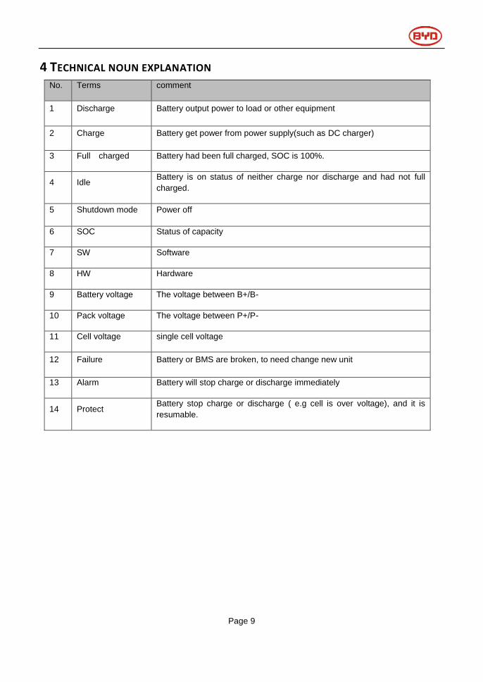
4 TECHNICAL NOUN EXPLANATION No. Terms comment
1 Discharge Battery output power to load or other equipment
2 Charge Battery get power from power supply(such as DC charger)
3 Full charged Battery had been full charged, SOC is 100%.
4 Idle Battery is on status of neither charge nor discharge and had not full
charged.
5 Shutdown mode Power off
6 SOC Status of capacity
7 SW Software
8 HW Hardware
9 Battery voltage The voltage between B+/B-
10 Pack voltage The voltage between P+/P-
11 Cell voltage single cell voltage
12 Failure Battery or BMS are broken, to need change new unit
13 Alarm Battery will stop charge or discharge immediately
14 Protect Battery stop charge or discharge ( e.g cell is over voltage), and it is
resumable.

Page 10
5 PRODUCT OVERVIEW 5.1 B-BOX System Brief introduction
B-Box is short name of battery box, as the energy storage part in the electric power system in household,
the box carries BYD’s lithium ferrum battery with excellent performance. There are 1/2/3/4 pcs batteries
modules in each box, and the box support parallel connection to expend capacity from 2.5Kwh to 80Kwh,
can meet various capacity requirement from users.
Figure 2 Internal drawing
Figure 1 External drawing
Page 11
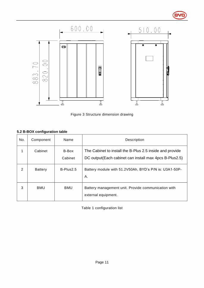
Figure 3 Structure dimension drawing
5.2 B-BOX configuration table
No. Component Name Description
1 Cabinet B-Box
Cabinet
The Cabinet to install the B-Plus 2.5 inside and provide
DC output(Each cabinet can install max 4pcs B-Plus2.5)
2 Battery B-Plus2.5 Battery module with 51.2V50Ah, BYD’s P/N is: U3A1-50P-
A.
3 BMU BMU Battery management unit. Provide communication with
external equipment.
Table 1 configuration list

Page 12
5.3 B-BOX System diagram
Figure 4 System diagram
5.4 General introduction of BMU
BMU is battery management unit which installed in cabinet, it as an function part in B-BOX
system to manage the battery’s charge and discharge, select information from battery and report
to inverter.
Main function:
CAN /RS485 communicate with inverter
RS485 communicate with battery/BMS
Dry contact terminal
Other Communication interface for maintenance
Charge and discharge management

Page 13
5.5 General introduction of B-Plus 2.5
5.5.1 B-Plus 2.5 brief introduction
B-Plus is the commercial name of BYD U3A1-50P-A backup battery with 51.2V& 50Ah which is designed for
energy storage application. B-Plus 2.5 is an integrated battery which consist of shell, BMS and cells.
Figure 5 B-Plus 2.5 overview
Figure 6 Display and communicate interface
Table 3 Display and communicate interface
No. Interface Mark Function
SOC LED SOC Indicate State of capacity of battery
RUN LED RUN Indicate the Plus is running status
ERR LED ERR ADDR Indicate error status
Alarm LED Alarm Indicate alarm status
RJ45 terminal RS232/RS485 Communication ports
Address ADDR When parallel connection, need setting address.
Alarm relay output 1.2.3.4 Not using
Test terminal B- B+ Measure battery voltage when testing.
Reset RESET Activity battery when no external power add on battery.
⑩
8
7
Display and
communicate interface
GND : Grounded terminal
P+: Positive terminal(DC+)
P- : Negative terminal(DC-)
Page 14
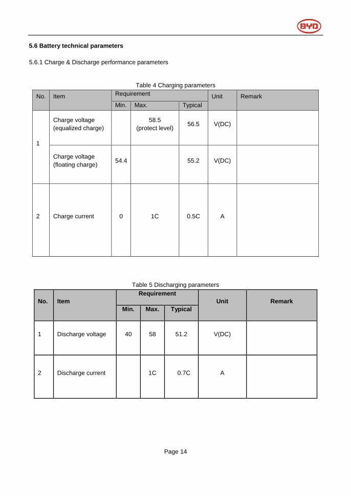
5.6 Battery technical parameters
5.6.1 Charge & Discharge performance parameters
Table 4 Charging parameters
No. Item Requirement Unit Remark
Min. Max. Typical
1
Charge voltage
(equalized charge)
58.5
(protect level) 56.5 V(DC)
Charge voltage
(floating charge) 54.4 55.2 V(DC)
2 Charge current 0 1C 0.5C A
Table 5 Discharging parameters
No. Item
Requirement
Unit Remark
Min. Max. Typical
1 Discharge voltage 40 58 51.2 V(DC)
2 Discharge current 1C 0.7C A
Page 15
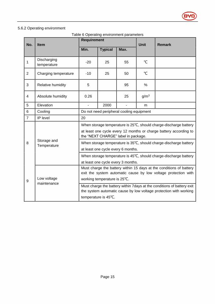
5.6.2 Operating environment
Table 6 Operating environment parameters
No. Item
Requirement
Unit Remark
Min. Typical Max.
1 Discharging
temperature -20 25 55 ℃
2 Charging temperature -10 25 50 ℃
3 Relative humidity 5 95 %
4 Absolute humidity 0.26 25 g/m3
5 Elevation - 2000 - m
6 Cooling Do not need peripheral cooling equipment
7 IP level 20
8 Storage and
Temperature
When storage temperature is 25℃, should charge-discharge battery
at least one cycle every 12 months or charge battery according to
the “NEXT CHARGE” label in package.
When storage temperature is 35℃, should charge-discharge battery
at least one cycle every 6 months.
When storage temperature is 45℃, should charge-discharge battery
at least one cycle every 3 months.
9 Low voltage
maintenance
Must charge the battery within 15 days at the conditions of battery
exit the system automatic cause by low voltage protection with
working temperature is 25℃.
Must charge the battery within 7days at the conditions of battery exit
the system automatic cause by low voltage protection with working
temperature is 45℃.
Page 16
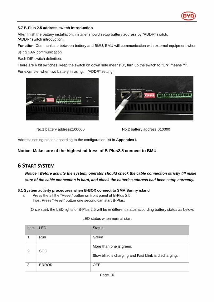
5.7 B-Plus 2.5 address switch introduction
After finish the battery installation, installer should setup battery address by “ADDR” switch.
“ADDR” switch introduction:
Function: Communicate between battery and BMU, BMU will communication with external equipment when
using CAN communication.
Each DIP switch definition:
There are 6 bit switches, keep the switch on down side means”0”, turn up the switch to “ON” means “1”.
For example: when two battery in using, “ADDR” setting:
No.1 battery address:100000 No.2 battery address:010000
Address setting please according to the configuration list in Appendex1.
Notice: Make sure of the highest address of B-Plus2.5 connect to BMU.
6 START SYSTEM Notice : Before activity the system, operator should check the cable connection strictly till make
sure of the cable connection is hard, and check the batteries address had been setup correctly.
6.1 System activity procedures when B-BOX connect to SMA Sunny island
i. Press the all the “Reset” button on front panel of B-Plus 2.5;
Tips: Press “Reset” button one second can start B-Plus;
Once start, the LED lights of B-Plus 2.5 will be in different status according battery status as below:
LED status when normal start
Item LED Status
1 Run Green
2 SOC
More than one is green.
Slow blink is charging and Fast blink is discharging.
3 ERROR OFF

Page 17
4 Alarm OFF
Remark:
Slow blink: Indicator light is on and off every 1s (0.5Hz).
Fast blink: indicator light is on and off every 0.25s(2HZ)
SOC status and indicate
Item Status Indicate
1 Four lights are all normally on Capacity is 100%-75% (including)
2 The last three lights are normally on Capacity is 74%-50% (including)
3 The last two lights are normally on Capacity is 49%-25% (including)
4 The last one light is normally on Capacity is 24%-0% (including)
ii. Switching on the Sunny Island
Requirements: ☐ The load-break switch in the DC cable must be closed. ☐ The Sunny Island must
not have switched itself.
Procedure:
• For systems with one Sunny Island, press the "On" button on the Sunny Island. • For systems with
up to three Sunny Island inverters, press and hold the "On" button on the master until an acoustic
signal sounds.
• For multicluster systems, press and hold the "On" button on each master until an acoustic signal
sounds.
☑ The inverter LED on each Sunny Island inverter is glowing orange and the Sunny Island
inverters are in standby.
i. Start the inverter;

Page 18
Requirement: ☐ All Sunny Island inverters must be switched on.
Procedure:
• Press the start-stop button on the Sunny Island and hold it until an acoustic signal sounds. or Press
and hold the button on the Sunny Remote Control until an acoustic signal sounds. ☑ The inverter
LED on each Sunny Island is glowing green.
ii. System start;
iii. Set up battery parameters on SRC of inverter.
Please refer to the “Battery Parameter setting” table in Appendix 2;
iv. System running;
6.2 System activity procedures when B-BOX connect to GOODWE inverter.
i. Download the APP on user’s cell phone and open the home page;
ii. Press the all the “Reset” button on front panel of B-Plus 2.5;
Tips: Press one second can start B-Plus;
Once start, the LED lights of B-Plus 2.5 will be in different status according battery status as below:
LED status when normal start
Item LED Status
1 Run Green
2 SOC More than one is green. Slow blink is charging and Fast blink is
discharging.
3 ERROR OFF
4 Alarm OFF
Remark:
Slow blink: Indicator light is on and off every 1s (0.5Hz).
Fast blink: indicator light is on and off every 0.25s(2HZ)
SOC status and indicate

Page 19
Item Status Indicate
1 Four lights are all normally on Capacity is 100%-75% (including)
2 The last three lights are normally on Capacity is 74%-50% (including)
3 The last two lights are normally on Capacity is 49%-25% (including)
4 The last one light is normally on Capacity is 24%-0% (including)
iii. Inverter activity;
iv. Go to the home page of APP, enter into the Battery Setting page, select “BYD B-BOX” battery, then
select “NEXT” until the last page, at last select “Start”.
i. System running;
6.3 System activity procedures when B-BOX connect to Solax inverter
i. Press the all the “Reset” button on front panel of B-Plus 2.5;
Tips: Press one second can start B-Plus;
Once start, the LED lights of B-Plus 2.5 will be in different status according battery status as below:
LED status when normal start
Item LED Status
1 Run Green
2 SOC More than one is green. Slow blink is charging and Fast blink is
discharging.
3 ERROR OFF
4 Alarm OFF
Remark:
Slow blink: Indicator light is on and off every 1s (0.5Hz).
Fast blink: indicator light is on and off every 0.25s(2HZ)
SOC status and indicate
Item Status Indicate
1 Four lights are all normally on Capacity is 100%-75% (including)
2 The last three lights are normally on Capacity is 74%-50% (including)

Page 20
3 The last two lights are normally on Capacity is 49%-25% (including)
4 The last one light is normally on Capacity is 24%-0% (including)
ii. Inverter activity;
iii. Go to the home page of APP, enter into the Battery Setting page, select “BYD B-BOX” battery, then
select “NEXT” until the last page, at last select “Start”.
iv. System running;
7 STOPPING THE SYSTEM 7.1 Stopping the system when B-BOX working with SMA SUNNY ISLAND
If you stop the system, the Sunny Island switches from operation into standby mode. In standby mode, the
Sunny Island discharges the battery due to its standby consumption.
Tip: For longer shut-down periods, switch off the Sunny Island .
i. Stopping the system
Procedure • Press and hold the start-stop button on the Sunny Island until the inverter LED is glowing
orange. or Press and hold the button on the Sunny Remote Control until the progress bar has run
down.
☑ The inverter LED on each Sunny Island is glowing orange. The Sunny Island inverters are in
standby.
ii. Switching off the Sunny Island
Requirement: ☐ The system is stopped.
Procedure: • Press and hold the "Off" button on the Sunny Island until an acoustic signal sounds.
☑ The inverter LED is off on all Sunny Island inverters.

Page 21
iii. Stopping the B-Plus 2.5;
Press all the “RESET” on front panel of B-Plus2.5 until all the led are off.
iv. The system stopping;
7.2 Stopping the system when B-BOX working with GOODWE inverter
i. Disconnect the load from inverter;
ii. Disconnect the solar panel from inverter;
iii. Disconnect the AC grid from inverter;
iv. Stopping the B-PLUS2.5: Press all the “RESET” on front panel of B-Plus2.5 until all the led are off;
v. System stopping;
7.3 Stopping the system when B-BOX working with Solax inverter
i. Disconnect the load from inverter;
ii. Disconnect the solar panel from inverter;
iii. Disconnect the AC grid from inverter;
iv. Stopping the B-PLUS2.5: Press all the “RESET” on front panel of B-Plus2.5 until all the led are off;
v. System stopping;
Page 22
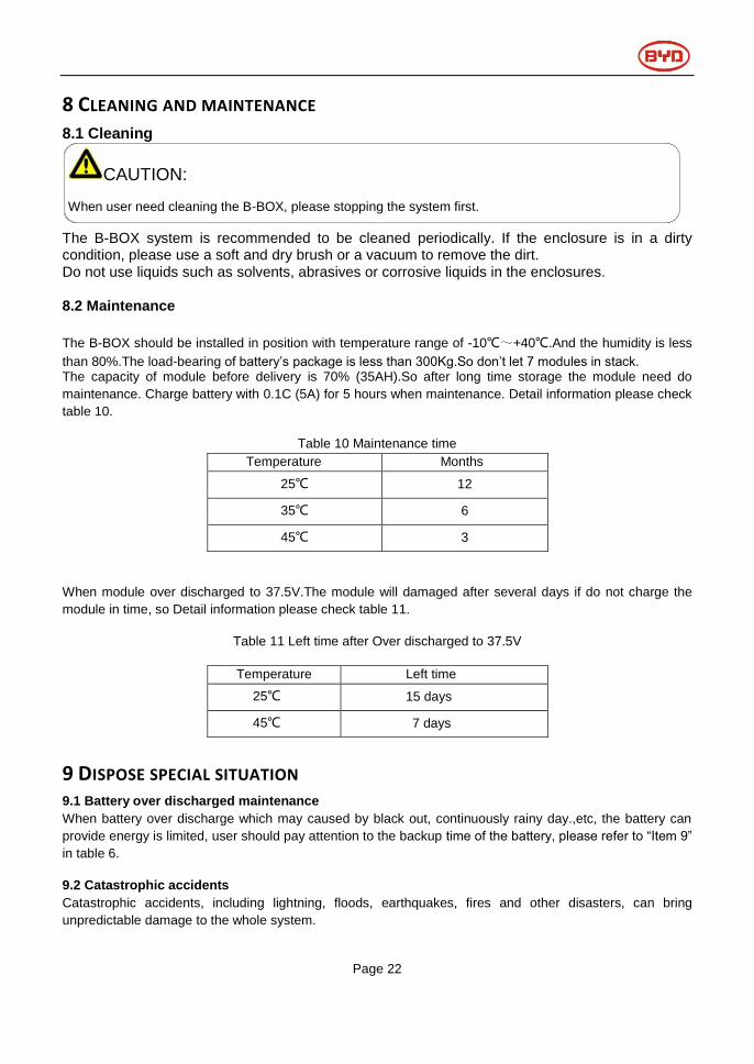
8 CLEANING AND MAINTENANCE 8.1 Cleaning
The B-BOX system is recommended to be cleaned periodically. If the enclosure is in a dirty condition, please use a soft and dry brush or a vacuum to remove the dirt. Do not use liquids such as solvents, abrasives or corrosive liquids in the enclosures.
8.2 Maintenance
The B-BOX should be installed in position with temperature range of -10℃~+40℃.And the humidity is less
than 80%.The load-bearing of battery’s package is less than 300Kg.So don’t let 7 modules in stack. The capacity of module before delivery is 70% (35AH).So after long time storage the module need do
maintenance. Charge battery with 0.1C (5A) for 5 hours when maintenance. Detail information please check
table 10.
Table 10 Maintenance time
Temperature Months
25℃ 12
35℃ 6
45℃ 3
When module over discharged to 37.5V.The module will damaged after several days if do not charge the
module in time, so Detail information please check table 11.
Table 11 Left time after Over discharged to 37.5V
Temperature Left time
25℃ 15 days
45℃ 7 days
9 DISPOSE SPECIAL SITUATION 9.1 Battery over discharged maintenance
When battery over discharge which may caused by black out, continuously rainy day.,etc, the battery can
provide energy is limited, user should pay attention to the backup time of the battery, please refer to “Item 9”
in table 6.
9.2 Catastrophic accidents
Catastrophic accidents, including lightning, floods, earthquakes, fires and other disasters, can bring
unpredictable damage to the whole system.
CAUTION:
When user need cleaning the B-BOX, please stopping the system first.

Page 23
10 BOX CONFIGURATION LIST WITH DIFFERENT INVERTER 10.1 B-BOX configuration list with SMA sunny island
1 Phase on Grid
Inverter Type B-Plus 2.5 Cabinet
SI 3.0M ≥1 ≥1
SI 4.4M ≥1 ≥1
SI 6.0H ≥1 ≥1
SI 8.0H ≥1 ≥1
Remark: Maximum B-Plus quantity is 32,Cabinet quantity is 8.
3 Phase on Grid
Inverter Type B-Plus 2.5 Cabinet
SI 3.0M ≥3 ≥1
SI 4.4M ≥4 ≥1
SI 6.0H ≥4 ≥1
SI 8.0H ≥4 ≥1
1 Phase off Grid
Inverter Type B-Plus 2.5 Cabinet
SI 3.0M ≥3 ≥1
SI 4.4M ≥3 ≥1
SI 6.0H ≥5 ≥2
SI 8.0H ≥5 ≥2
3 Phase off Grid
Inverter Type B-Plus 2.5 Cabinet
SI 3.0M ≥8 ≥2
SI 4.4M ≥8 ≥2
SI 6.0H ≥12 ≥3
SI 8.0H ≥12 ≥3
Remark: Maximum B-Plus quantity is 32,Cabinet quantity is 8.

Page 24
10.2 B-BOX configuration list with GOODWE ES inverter
1 Phase on Grid
Inverter Type B-Plus 2.5 Cabinet
4.6kW ≥11 ≥1
1 Phase off Grid
Inverter Type B-Plus 2.5 Cabinet
4.6kW ≥2 ≥1
Remark: Maximum B-Plus quantity is 32, Cabinet quantity is 8.
10.3 B-BOX configuration list with GOODWE BP inverter
1 Phase on Grid
Inverter Type B-Plus 2.5 Cabinet
2.5kW ≥1 ≥1
Remark: Maximum B-Plus quantity is 32, Cabinet quantity is 8.
10.4 B-BOX configuration list with Solax inverter
1 Phase on Grid
Inverter Type B-Plus 2.5
SK-SU3000 ≥1
SK-SU3700 ≥1
SK-SU5000 ≥1
1 This configuration is only for self consumption application.

Page 25
11 NORMAL ISSUES AND SOLUTIONS 11.1 Normal alarm and solution display on SMA sunny island SRC
SMA SRC Reason Solution
F221 External Alarm-Invalid BatType Reset battery type to "Li" on SRC.
F920(XA01General) 1.All the batteries are failed to
communicate at the same time;
2.BMU and battery are failed to
RS485communicate;
1.Inspect whether the RS485 communicate
cable had been connected correctly and
reliability;
2.Inspect DIP switch setting according to the
DIP switch setting table in user manual;
3.Change BMU in cabinet;
F930(XA11Short) External Alarm - Short circuit 1.Power off;
2.Inspect short connection of cable between
P+&P-;
3.If short connection is confirmed, please
reconnect cable correctly;
4.restart battery;
F952 External Alarm –ExtBMS Timeout 1.Check the CAN communication, should
connect well.
2.Change BMU.
W936(XW01General) External Warning - General 1.Inspect whether the RS485 communicate
cable had been connected correctly and
reliability;
2.Inspect DIP switch setting according to the
Address setting table;
W937(XW02DcHiVolt) External Warning - Battery High Voltage Normal alarm and do not need to deal with;
W938(XW03DcLoVolt) External Warning - Battery Low Voltage Normal alarm and do not need to deal with;
W939(XW04DcHiTmp) External Warning - Battery High Temp Normal alarm and do not need to deal with;
W940(XW05DcLoTmp) External Warning - Battery Low Temp Normal alarm and do not need to deal with;
W941(XW06DcHiTmpC) External Warning - Battery High Temp
Charge
Normal alarm and do not need to deal with;
W942(XW07DcLoTmpC) External Warning - Battery Low Temp
Charge
Normal alarm and do not need to deal with;

Page 26
W943(XW08DcHiCur) External Warning - Battery High Current Normal alarm and do not need to deal with;
W944(XW09DcHiChgCur) External Warning - Battery High Current
Charge
Normal alarm and do not need to deal with;
W953 External Warning – ExtBMS Timeout 1.Check the CAN communication, should
connect well.
2.Change BMU.
11.2 Normal alarm and solution display on B-Plus 2.5 B-Plus display info Reason Solution
LED Yellow led(Alarm) blinks for
0.5Hz,other led are on off
continuously;
Battery power off abnormal; 1.Press "RESET" button for 2-3 secs
untill battery can work normal;
2.If yellow blink continuously, need
change battery;
Yellow led(Alarm),Yellow led
on and buzzing with 4 times.
Protected or external connection
incorrect;
1.Power off the battery;
2.Inspect short/reverse connection
of cable between P+&P-;
3.If short/reverse connection is
confirmed, please reconnect cable
correctly;
4.restart battery;
Buzzer Buzzing for 4 times Short/reverse connection; 1.Power off;
2.Inspect short/reverse connection
of cable between P+&P-;
3.If short/reverse connection is
confirmed, please reconnect cable
correctly;
4.restart battery;

Page 27
12 WARRANTY BYD provide warranty when this product is installed and used do not beyond description in user manual,
installation manual and warranty letter.
13 LOGIN IN AFTER SERVICE WEB In order to get after service in time, after installation, please login your B-BOX information in our after service
operator web:
http://www.eft-systems.de/de/content/1/unternehmen
14 CONTACT For technical problems or inquiries for usage, please contact our installation company.
To receive customer support, the following information is required.
Product type
Serial Number
Connected PV module type and number
Option equipment
Any using problem please contact us by below address:
Contact us:
China
BYD LITHIUM BATTERY Co.,LTD
Customer Service Mailbox: [email protected]
Telephone:+86 0755 89888888
Address: No.1,Baoping Road,Baolong lndustrial Town Longgang Shenzhen, 518116, P.R.China
Germany
EFT Energy for tomorrow
Customer Service Mailbox: [email protected]
Telephone : +49-6996759811
Address : Buchenstraße, 37 Lohr a. Main 97816 Germany

Page 28
APPENDIX 1 : BATTERY ADDRESS SETTING LIST Battery address setting list (from 1~32 batteries):
Battery No. Address Battery No. Address
1 100000 17 100010
2 010000 18 010010
3 110000 19 110010
4 001000 20 001010
5 101000 21 101010
6 011000 22 011010
7 111000 23 111010
8 000100 24 000110
9 100100 25 100110
10 010100 26 010110
11 110100 27 110110
12 001100 28 001110
13 101100 29 101110
14 011100 30 011110
15 111100 31 111110
16 000010 32 000001

Page 29
APPENDIX 2 : BATTERY PARAMETER SETTING TABLE
Battery Parameter setting table for B-BOX2.5:
Charging the battery Usage through battery backup system without increased self-consumption
Parameters Setup value
003.07Batt Typ Li Lon_Ext-BMS
003.10Batt Cpynom 50
262.01ProtResSOC 6
262.02BatResSOC 12
Charging the battery usage through battery backup system with increased self-consumption
Parameters Setup value
003.07Batt Typ Li Lon_Ext-BMS
003.10Batt Cpynom 50
261.01SlfCsmplncEna Enable
261.03Saisonenable Yes
262.01ProtResSOC 3
262.02BatResSOC 2
262.03BUResSOC 0
262.04PVResSOC 5
262.05MinSlfCsmpSOC 70
Charging the battery usage through system for increased self-consumption without a battery
backup grid
Parameters Setup value
003.07Batt Typ Li Lon_Ext-BMS
003.10Batt Cpynom 50
261.01SlfCsmplncEna Enable
261.03Saisonenable Yes
262.01ProtResSOC 3
262.02BatResSOC 2
262.04PVResSOC 5
262.03BUResSOC 0
262.05MinSlfCsmpSOC 70
Charging the battery protection mode in off-grid system
Parameters Setup value
003.07Batt Typ Li Lon_Ext-BMS
003.10Batt Cpynom 50
223.05BatPro1Soc 18
223.06BatPro2Soc 12
223.07BatPro3Soc 6

Page 30
Battery Parameter setting table for B-BOX5.0:
Charging the battery Usage through battery backup system without increased self-consumption
Parameters Setup value
003.07Batt Typ Li Lon_Ext-BMS
003.10Batt Cpynom 100
262.01ProtResSOC 3
262.02BatResSOC 6
Charging the battery usage through battery backup system with increased self-consumption
Parameters Setup value
003.07Batt Typ Li Lon_Ext-BMS
003.10Batt Cpynom 100
261.01SlfCsmplncEna Enable
261.03Saisonenable Yes
262.01ProtResSOC 3
262.02BatResSOC 2
262.03BUResSOC 0
262.04PVResSOC 4
262.05MinSlfCsmpSOC 85
Charging the battery usage through system for increased self-consumption without a battery
backup grid
Parameters Setup value
003.07Batt Typ Li Lon_Ext-BMS
003.10Batt Cpynom 100
261.01SlfCsmplncEna Enable
261.03Saisonenable Yes
262.01ProtResSOC 3
262.02BatResSOC 2
262.04PVResSOC 4
262.03BUResSOC 0
262.05MinSlfCsmpSOC 85
Charging the battery protection mode in off-grid system
Parameters Setup value
003.07Batt Typ Li Lon_Ext-BMS
003.10Batt Cpynom 100
223.05BatPro1Soc 9
223.06BatPro2Soc 6
223.07BatPro3Soc 3
Page 31
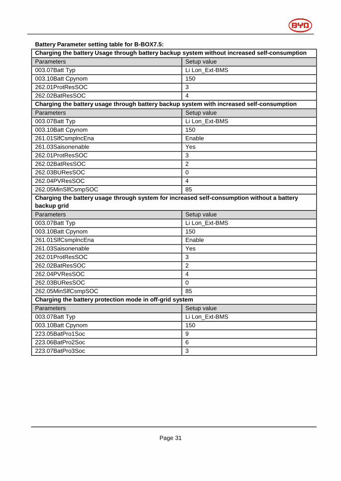
Battery Parameter setting table for B-BOX7.5:
Charging the battery Usage through battery backup system without increased self-consumption
Parameters Setup value
003.07Batt Typ Li Lon_Ext-BMS
003.10Batt Cpynom 150
262.01ProtResSOC 3
262.02BatResSOC 4
Charging the battery usage through battery backup system with increased self-consumption
Parameters Setup value
003.07Batt Typ Li Lon_Ext-BMS
003.10Batt Cpynom 150
261.01SlfCsmplncEna Enable
261.03Saisonenable Yes
262.01ProtResSOC 3
262.02BatResSOC 2
262.03BUResSOC 0
262.04PVResSOC 4
262.05MinSlfCsmpSOC 85
Charging the battery usage through system for increased self-consumption without a battery
backup grid
Parameters Setup value
003.07Batt Typ Li Lon_Ext-BMS
003.10Batt Cpynom 150
261.01SlfCsmplncEna Enable
261.03Saisonenable Yes
262.01ProtResSOC 3
262.02BatResSOC 2
262.04PVResSOC 4
262.03BUResSOC 0
262.05MinSlfCsmpSOC 85
Charging the battery protection mode in off-grid system
Parameters Setup value
003.07Batt Typ Li Lon_Ext-BMS
003.10Batt Cpynom 150
223.05BatPro1Soc 9
223.06BatPro2Soc 6
223.07BatPro3Soc 3

Page 32
Battery Parameter setting table for B-BOX10.0:
Charging the battery Usage through battery backup system without increased self-consumption
Parameters Setup value
003.07Batt Typ Li Lon_Ext-BMS
003.10Batt Cpynom 200
262.01ProtResSOC 3
262.02BatResSOC 4
Charging the battery usage through battery backup system with increased self-consumption
Parameters Setup value
003.07Batt Typ Li Lon_Ext-BMS
003.10Batt Cpynom 200
261.01SlfCsmplncEna Enable
261.03Saisonenable Yes
262.01ProtResSOC 3
262.02BatResSOC 2
262.03BUResSOC 0
262.04PVResSOC 4
262.05MinSlfCsmpSOC 85
Charging the battery usage through system for increased self-consumption without a battery
backup grid
Parameters Setup value
003.07Batt Typ Li Lon_Ext-BMS
003.10Batt Cpynom 200
261.01SlfCsmplncEna Enable
261.03Saisonenable Yes
262.01ProtResSOC 3
262.02BatResSOC 2
262.04PVResSOC 4
262.03BUResSOC 0
262.05MinSlfCsmpSOC 85
Charging the battery protection mode in off-grid system
Parameters Setup value
003.07Batt Typ Li Lon_Ext-BMS
003.10Batt Cpynom 200
223.05BatPro1Soc 9
223.06BatPro2Soc 6
223.07BatPro3Soc 3