user’s manual dtap3000d dtsx3000 data conversion software
TRANSCRIPT
User’s Manual
IM 39J02B40-03E
DTAP3000D DTSX3000 Data Conversion Software WITSML1.3.1.1 Guide
IM 39J02B40-03E 1st Edition

Blank Page
< Introduction > i
Introduction
About this Manual Thank you for purchasing the DTSX3000 Data Conversion Software WITSML 1.3.1.1 (DTAP3000D). This document describes the functions, operation and usage precautions of the DTAP3000D software. Read it carefully before using the software to ensure proper use. After reading, save this document in an accessible location for easy reference during software use. Besides this manual, the table below lists three other manuals related to the DTSX3000 Distribution Temperature Sensor. Read these manuals as well.
Manual name Document No. Description DTSX3000 Distributed Temperature Sensor Guide
IM39J06B40-01E This document describes the functions, operation and usage precautions of the DTSX3000 Distributed Temperature Sensor.
DTSX3000 Communications (Modbus) Guide
IM39J06B40-02E This manual describes commands for controlling the DTSX3000 Distributed Temperature Sensor.
DTAP3000 DTSX3000 Control Visualization Software Guide
IM39J02B40-01E This document describes the functions, operation and usage precautions of the DTSX3000 Control Visualization Software, which can be used to configure the DTSX Series Distributed Temperature Sensor and display its measurement result.
DTAP3000 DTSX3000 Control Visualization Software LAS 2.0 Data Conversion Guide
IM39J02B40-02E This document describes the functions, operation and usage precautions of the software for converting and transmitting measurement data of the DTSX Series Distributed Temperature Sensor in LAS format.
Caution • This document describes the DTAP3000D Software R1.01.01. You can check your
software version by selecting [Help] from the software menu bar. • YOKOGAWA reserves the right to make improvements in the manuals and product
at any time, without notice or obligation. Moreover, actual screen display in the software may differ somewhat from the screen display contained in this document.
• If you have any questions, or you find mistakes or omissions in the manuals, please contact our sales representative or your local distributor.
• The use and operation of Windows is not described in this document. • No part of the manual may be transferred or reproduced without prior written
consent from YOKOGAWA.
< Introduction > ii
Trademarks and licensed software The following names are trademarks or registered trademarks of their respective holders. • DTSX200, DTSX3000, DTSX is a trademark of Yokogawa Electric Corporation. • Microsoft and Windows are registered trademarks or trademarks of Microsoft
Corporation in the United States and other countries. • Adobe and Acrobat are trademarks of Adobe systems Incorporated registered in
certain regions. • Ethernet is a registered trademark of Xerox Corporation.• IBM and IBM-PC/AT are registered trademarks of IBM Corporation. • Other company and product names appearing in this document are trademarks or
registered trademarks of their respective holders. • Registered trademarks and trademarks in this document are not displayed with TM
or the ® mark. • The following third-party software are used in this software:
NetAdvantage Icons © 2011 – Infragistics Products
< CONTENTS > iii
CONTENTS Introduction ................................................................................................ i CONTENTS ............................................................................................... iii 1. Before Using the Software .............................................................. 1
1.1 DTSX3000 Data Conversion Software WITSML 1.3.1.1 Function Description ................................................................................................... 1
1.2 System Requirements ................................................................................. 2 1.3 Installation Procedure ................................................................................. 4 1.4 Network Setup ............................................................................................. 4
2. Using the Software ........................................................................... 5 2.1 Operation Flowchart ................................................................................... 5 3.1 Startup Sequence ........................................................................................ 7 3.2 Running the Software ................................................................................. 8 3.3 Connecting to DTSX Series ........................................................................ 9 3.4 Registering License .................................................................................. 15 3.5 Removing License ..................................................................................... 17 3.6 Online and Offline States .......................................................................... 19 3.7 Terminating the Software .......................................................................... 22 4.1 Window Components and Functions ...................................................... 24
4.1.1 List of Windows and Dialogs .......................................................... 25 4.1.2 Main Window .................................................................................. 25 4.1.3 Solution Tree Window .................................................................... 28
4.2 Loading and Saving Settings ................................................................... 31 4.2.1 Loading and Saving Settings from the Start Menu ......................... 31 4.2.2 Loading and Saving Settings from Context Menu .......................... 34
4.3 Copying, Pasting and Defaulting Settings .............................................. 37 4.3.1 Copying, Pasting and Defaulting Settings from the Main
Window Menu ................................................................................ 37 4.3.2 Copying, Pasting and Defaulting Settings from Context Menu ...... 39
4.4 Displaying Windows and Dialogs ............................................................ 41 4.4.1 Menu Items for Displaying Windows (in main window) .................. 41 4.4.2 Nodes for Displaying Windows (in Solution Tree Window) ............ 41 4.4.3 Window Operations ........................................................................ 42 4.4.4 Menu Items for Displaying Dialogs (in main window) ..................... 65 4.4.5 Nodes for Displaying Dialogs (in Solution Tree Window) ............... 66
DTAP3000D DTSX3000 Data Conversion Software WITSML1.3.1.1 Guide IM 39J02B40-03E
< CONTENTS > iv
4.4.6 Dialog Operations .......................................................................... 67 4.5 Starting and Stopping Measurement ....................................................... 69
4.5.1 Starting Conversion from Menu (in main window) .......................... 71 4.5.2 Starting Conversion from Context Menu (in Solution Tree
window) .......................................................................................... 71 4.5.3 Sever & Transmit File Settings ....................................................... 72
4.6 Starting and Stopping File Transfer ......................................................... 74 4.6.1 Starting and Stopping Transfer from Menu (in main window) ........ 75 4.6.2 Starting and Stopping Transfer from Context Menu (in Solution
Tree window) .................................................................................. 75 4.6.3 File Transfer Settings ..................................................................... 76 4.6.4 File Storage Settings ...................................................................... 78
4.7 Status Bar ................................................................................................... 80 4.8 Status Display ............................................................................................ 82 4.9 Messages ................................................................................................... 83 4.10 Alarms ......................................................................................................... 84 4.11 Help ............................................................................................................. 85
5. WITSML File Configuration ........................................................... 87 5.1 File Settings ............................................................................................... 87 5.2 File Transmission Settings ....................................................................... 91 5.3 WITSML Settings ....................................................................................... 94
6. WITSML File Output ..................................................................... 104 6.1 Overview of Data Output ........................................................................ 104 6.2 Configuring Data Output Conditions ..................................................... 105 6.3 Executing Data Output ............................................................................ 115 6.4 Measurement Data Output ...................................................................... 115 6.5 Retrieving Measurement Data ................................................................ 115
7. Modbus Address Map .................................................................. 116 7.1 List of Holding Registers ........................................................................ 116 7.2 Description of Holding Registers .......................................................... 116 7.3 List of Input Registers............................................................................. 122 7.4 Description of Input Registers ............................................................... 122
Appendix. Messages ................................................................. 123 Appendix A List of Messages ........................................................................ 124 Appendix B List of Transmission Messages ................................................ 130
Revision Information ................................................................................. i
< 1. Before Using the Software > 1
IM 39J02B40-03E
1. Before Using the Software
1.1 DTSX3000 Data Conversion Software WITSML 1.3.1.1 Function Description
HMI software Monitoring
Host data server
Data
HMI softwareMonitoring
HMI softwareControl and WITSML data
conversion
DCS
Protocols:- SSH- SCP(SFTP) Ethenet
HTTP (S) protocol
Configuration data
WITSML data
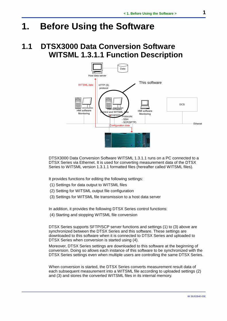
DTSX3000 Data Conversion Software WITSML 1.3.1.1 runs on a PC connected to a DTSX Series via Ethernet. It is used for converting measurement data of the DTSX Series to WITSML version 1.3.1.1 formatted files (hereafter called WITSML files). It provides functions for editing the following settings: (1) Settings for data output to WITSML files (2) Setting for WITSML output file configuration (3) Settings for WITSML file transmission to a host data server In addition, it provides the following DTSX Series control functions: (4) Starting and stopping WITSML file conversion DTSX Series supports SFTP/SCP server functions and settings (1) to (3) above are synchronized between the DTSX Series and this software. These settings are downloaded to this software when it is connected to DTSX Series and uploaded to DTSX Series when conversion is started using (4). Moreover, DTSX Series settings are downloaded to this software at the beginning of conversion. Doing so allows each instance of this software to be synchronized with the DTSX Series settings even when multiple users are controlling the same DTSX Series. When conversion is started, the DTSX Series converts measurement result data of each subsequent measurement into a WITSML file according to uploaded settings (2) and (3) and stores the converted WITSML files in its internal memory.
This software
< 1. Before Using the Software > 2
IM 39J02B40-03E
WITSML files stored in the DTSX Series can be transmitted to a host data server using HTTP and HTTPS client functions, which are supported by the DTSX Series.
SEE ALSO For more information, read the DTSX3000 Guide (IM39J06B40-01E) and the DTAP200 Guide (IM39J02B45-01E).
IMPORTANT
- Up to eight instances of the DTAP3000, DTAP3000LAS and DTAP3000D (this software) software applications combined can be run concurrently on a PC.
- However, running multiple instances of the applications on a PC may slow down response time significantly due to heavy processing load so the use of a powerful PC is recommended if concurrent execution is required.
- Up to four users of the DTAP3000, DTAP3000LAS and DTAP3000D (this software) software applications combined can be connected to the DTSX3000 concurrently.
- Up to four users of the DTAP3000, DTAP3000LAS and DTAP3000D, DTAP200, DTAP200LAS and DTAP200D (this software) software applications combined can be connected to the DTSX200 concurrently.
- Uploaded settings are saved even if the DTSX Series is shutdown or rebooted. However, for a DTSX200 installed with conversion functions for multiple formats, only the settings of the last conversion executed are saved while the settings of the other conversions are initialized when the DTSX200 is shutdown or rebooted. For instance, for the sample sequence operations given below, the WITSML1.3.1.1 conversion settings are saved but the LAS2.0 conversion settings are initialized:
(1) Start LAS2.0 conversion (2) Stop LAS2.0 conversion (3) Start WITSML1.3.1.1. conversion (4) Stop WITSML1.3.1.1. conversion (5) Reboot DTSX200
1.2 System Requirements ● Operating system (OS)
The software runs on the following operating systems: - Windows7 Home Premium SP1 English/Japanese (x86 / x64) - Windows7 Ultimate SP1 English/Japanese (x86 / x64) - Windows7 Professional SP1 English/Japanese (x86 / x64) - Windows7 Enterprise SP1 English/Japanese (x86 / x64)
(.NET Framework 4.0 is required) - Windows8.1 English/Japanese (x86 / x64) - Windows8.1 Pro English/Japanese (x86 / x64) - Windows8.1 Enterprise English/Japanese (x86 / x64)
< 1. Before Using the Software > 3
IM 39J02B40-03E
The software is not guaranteed to run properly on other operating systems not listed above.
● Personal computer (PC) The PC must be installed with any of the above operating systems, as well as a CPU and memory meeting the following requirements: Dual-core 32-bit processor 2 GHz or better 2 GB or more memory
● Hard disk 2 GB or more free space
● Optical disk drive An optical disk drive compatible with the operating system and capable of reading CD-ROMs is required for software installation.
● Mouse, keyboard and other input devices Input devices supported by the operating system
● Display A video card recommended for use with the operating system and display device supporting 1024X768 dpi resolution or higher and 65536 colors or more, and supported by the operating system
● Printer Printer and printer driver compatible with the operating system
● Ethernet adaptor Ethernet adaptor (100BASE-TX or 10BASE-T) supported by the operating system
● Baud rate (throughput) Baud rate between PC and DTSX Series: 500 kbps or higher Module operation may be unstable if baud rate (throughput) is below 500 kbps.
● PDF Reader Adobe Reader X is required for reading this guide.
< 1. Before Using the Software > 4
IM 39J02B40-03E
TIP - To install the software in Windows7/8.1, you must log in as a user with Administrator authority.
1.3 Installation Procedure SEE ALSO Read the DTAP3000D installation manual (IM39J02B40-07E) bundled with the software.
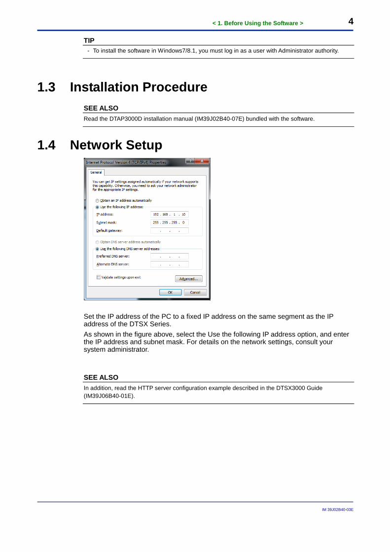
1.4 Network Setup
Set the IP address of the PC to a fixed IP address on the same segment as the IP address of the DTSX Series. As shown in the figure above, select the Use the following IP address option, and enter the IP address and subnet mask. For details on the network settings, consult your system administrator.
SEE ALSO In addition, read the HTTP server configuration example described in the DTSX3000 Guide (IM39J06B40-01E).
< 1. Before Using the Software > 5
IM 39J02B40-03E
2. Using the Software
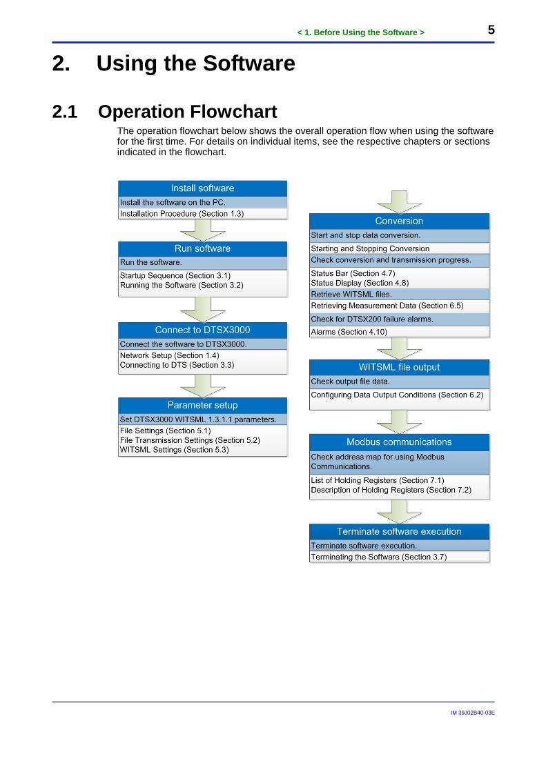
2.1 Operation Flowchart The operation flowchart below shows the overall operation flow when using the software for the first time. For details on individual items, see the respective chapters or sections indicated in the flowchart.

6
IM 39J02B40-03E
Blank Page
<3. Running and Terminating the Software > 7
IM 39J02B40-03E
3. Running and Terminating the Software
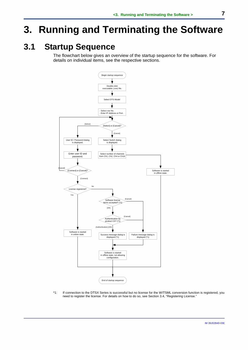
3.1 Startup Sequence The flowchart below gives an overview of the startup sequence for the software. For details on individual items, see the respective sections.
Begin startup sequence
End of startup sequence
Double-click executable (.exe) file.
Software is started in offline state.
- Select row No. - Enter IP Address or Port.
[Select] or [Cancel]?
Select Switch dialogis displayed.
Select number of channels from Ch1, Ch2, Ch4 or Ch16
[Cancel]
User ID / Password dialogis displayed.
[Select]
Enter user ID and password.
[Connect] or [Cancel]?
[Connect]
Software is started in online state.
[Cancel]
License registered?
Software license terms accepted? (*1)
No
Yes
[OK]
[Cancel]
Software is started in offline state, not allowing
configuration.
Success message dialog is displayed (*1)
Failure message dialog is displayed (*1)
Authentication by product CD? (*1)
[Cancel]
(Authentication) [OK]
Select DTS Model
*1: If connection to the DTSX Series is successful but no license for the WITSML conversion function is registered, you
need to register the license. For details on how to do so, see Section 3.4, “Registering License.”
<3. Running and Terminating the Software > 8
IM 39J02B40-03E
3.2 Running the Software ● Running the software from the Start menu
In Microsoft Windows running on a PC, select Start>All Programs> YOKOGAWA DTSX3000>DTSX3000 Data Conversion Software WITSML 1.3.1.1.
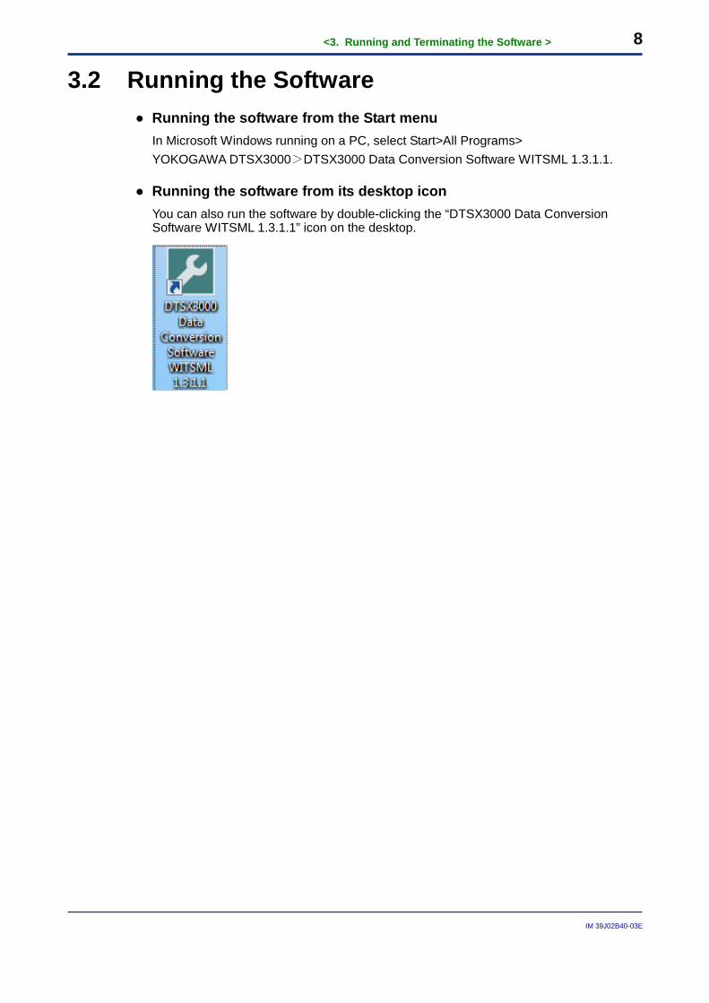
● Running the software from its desktop icon You can also run the software by double-clicking the “DTSX3000 Data Conversion Software WITSML 1.3.1.1” icon on the desktop.
<3. Running and Terminating the Software > 9
IM 39J02B40-03E
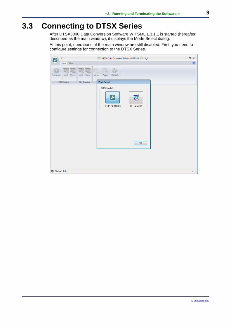
3.3 Connecting to DTSX Series After DTSX3000 Data Conversion Software WITSML 1.3.1.1 is started (hereafter described as the main window), it displays the Mode Select dialog. At this point, operations of the main window are still disabled. First, you need to configure settings for connection to the DTSX Series.
<3. Running and Terminating the Software > 10
IM 39J02B40-03E
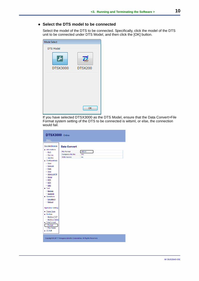
● Select the DTS model to be connected Select the model of the DTS to be connected. Specifically, click the model of the DTS unit to be connected under DTS Model, and then click the [OK] button.
If you have selected DTSX3000 as the DTS Model, ensure that the Data Convert>File Format system setting of the DTS to be connected is witsml, or else, the connection would fail.
<3. Running and Terminating the Software > 11
IM 39J02B40-03E
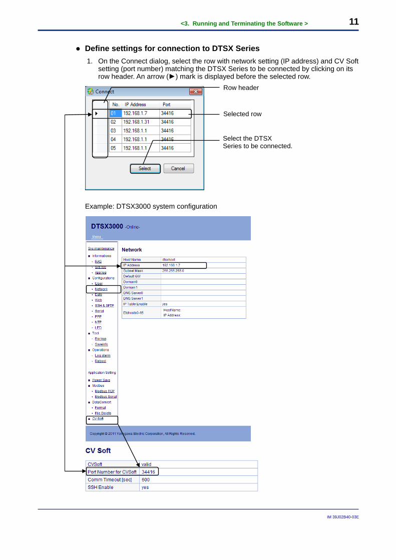
● Define settings for connection to DTSX Series 1. On the Connect dialog, select the row with network setting (IP address) and CV Soft
setting (port number) matching the DTSX Series to be connected by clicking on its row header. An arrow (►) mark is displayed before the selected row.
Example: DTSX3000 system configuration
Row header
Selected row
Select the DTSX Series to be connected.
<3. Running and Terminating the Software > 12
IM 39J02B40-03E
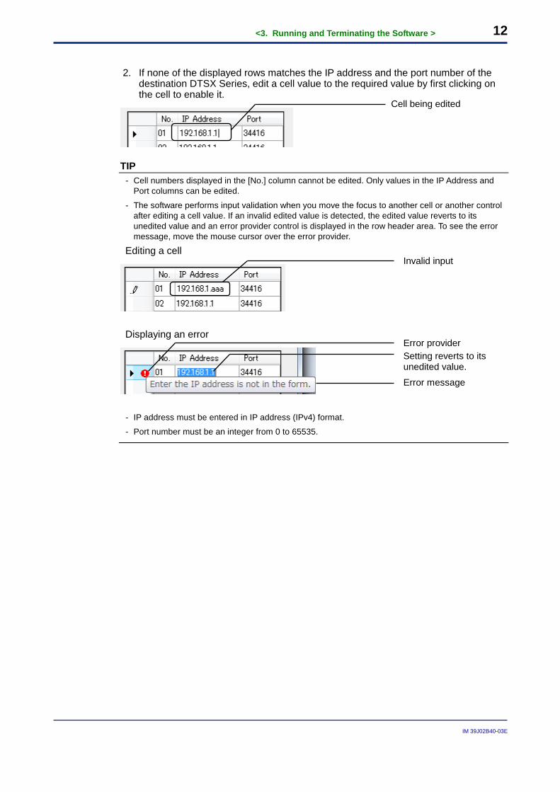
2. If none of the displayed rows matches the IP address and the port number of the
destination DTSX Series, edit a cell value to the required value by first clicking on the cell to enable it.
TIP - Cell numbers displayed in the [No.] column cannot be edited. Only values in the IP Address and
Port columns can be edited.
- The software performs input validation when you move the focus to another cell or another control after editing a cell value. If an invalid edited value is detected, the edited value reverts to its unedited value and an error provider control is displayed in the row header area. To see the error message, move the mouse cursor over the error provider.
Editing a cell
Displaying an error
- IP address must be entered in IP address (IPv4) format.
- Port number must be an integer from 0 to 65535.
Cell being edited
Invalid input
Setting reverts to its unedited value.
Error message
Error provider
<3. Running and Terminating the Software > 13
IM 39J02B40-03E
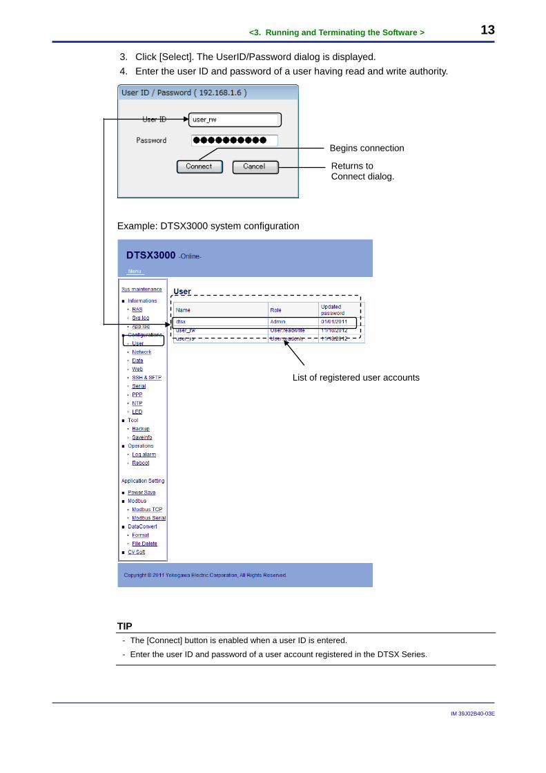
3. Click [Select]. The UserID/Password dialog is displayed. 4. Enter the user ID and password of a user having read and write authority.
Example: DTSX3000 system configuration
TIP - The [Connect] button is enabled when a user ID is entered.
- Enter the user ID and password of a user account registered in the DTSX Series.
Begins connection
List of registered user accounts
Returns to Connect dialog.
<3. Running and Terminating the Software > 14
IM 39J02B40-03E
SEE ALSO For details on how to register a user account, see the DTSX3000 Guide (IM39J06B40-01E).
5. Clicking [Connect] initiates connection to DTSX Series. Clicking [Cancel] returns to
the Connect dialog. When connected to a DTSX Series with no registered license for the WITSML conversion function, you need to register a license for the function.
SEE ALSO See Section 3.4, “Registering License,” for details.
TIP - When you click [Connect] on the UserID/Password dialog, edited settings on the Connect dialog
are saved and will be displayed in the Connect dialog when the software is next executed. Up to five IP address and port number pairs can be saved. Entered values are not saved if you click [Cancel].
- Values entered in the UserID/Password dialog are not saved and must be re-entered each time.
IMPORTANT
- Only users with read and write authority are allowed to connect to the DTSX Series. - Connection can only be made to a DTS whose model matches the DTS Model
setting selected on the Mode Select dialog.
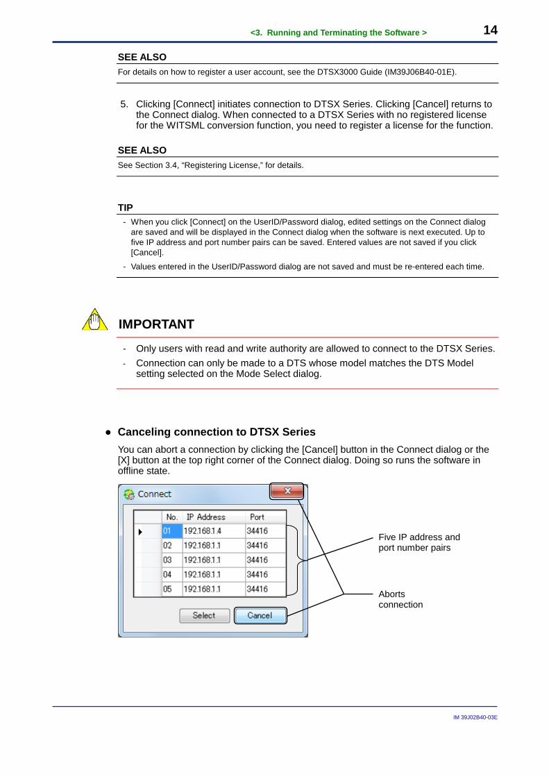
● Canceling connection to DTSX Series You can abort a connection by clicking the [Cancel] button in the Connect dialog or the [X] button at the top right corner of the Connect dialog. Doing so runs the software in offline state.
Aborts connection
Five IP address and port number pairs
<3. Running and Terminating the Software > 15
IM 39J02B40-03E
3.4 Registering License To use the WITSML data conversion function of the DSX3000, a license for the WITSML data conversion function (hereinafter referred to simply as license) needs to be registered on the DTSX3000. This license is not registered on a new DTSX3000 before delivery. To register the license using this software, follow the procedure described below. 1. Insert the CD-ROM of this software into the CD-ROM drive of the PC. 2. Run the software and connect to the DTSX3000.
SEE ALSO For details on how to do so, see Section 3.2, “Running the Software,” and Section 3.3, “Connecting to DTSX Series.”
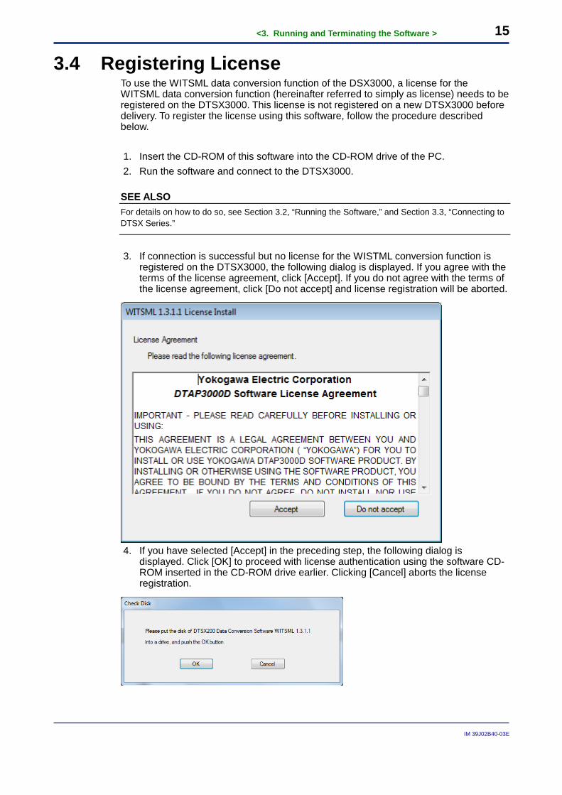
3. If connection is successful but no license for the WISTML conversion function is
registered on the DTSX3000, the following dialog is displayed. If you agree with the terms of the license agreement, click [Accept]. If you do not agree with the terms of the license agreement, click [Do not accept] and license registration will be aborted.
4. If you have selected [Accept] in the preceding step, the following dialog is
displayed. Click [OK] to proceed with license authentication using the software CD-ROM inserted in the CD-ROM drive earlier. Clicking [Cancel] aborts the license registration.
<3. Running and Terminating the Software > 16
IM 39J02B40-03E
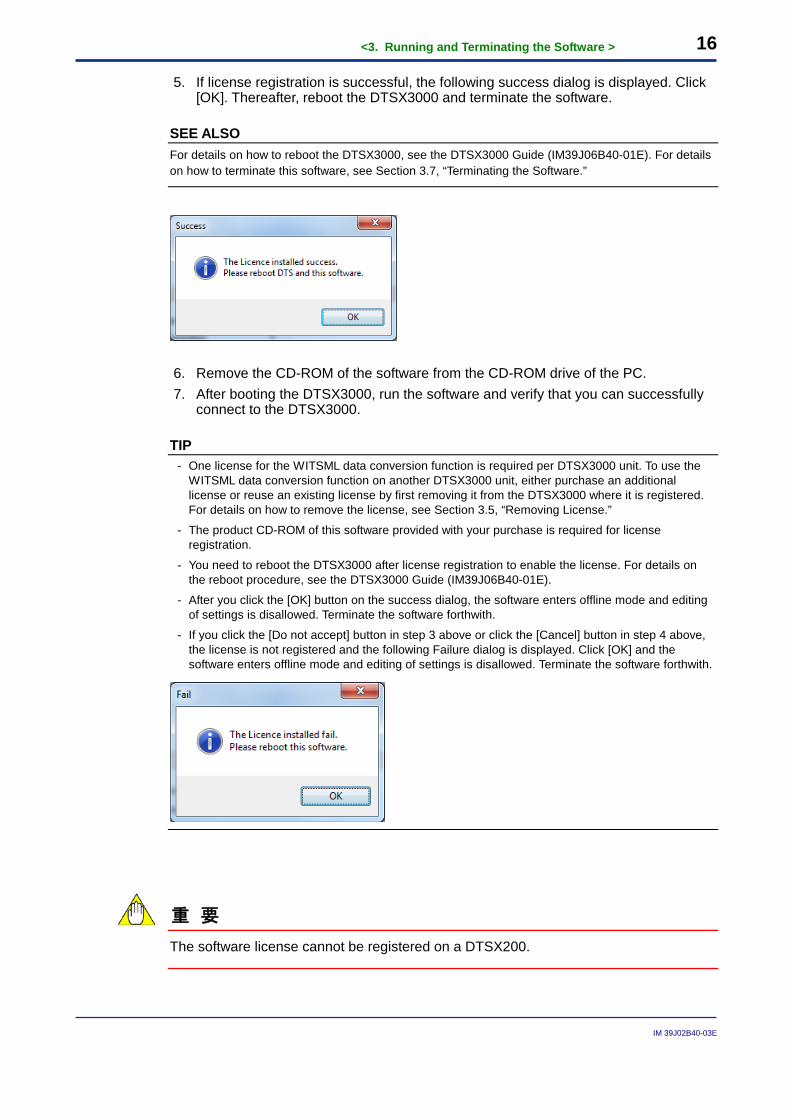
5. If license registration is successful, the following success dialog is displayed. Click [OK]. Thereafter, reboot the DTSX3000 and terminate the software.
SEE ALSO For details on how to reboot the DTSX3000, see the DTSX3000 Guide (IM39J06B40-01E). For details on how to terminate this software, see Section 3.7, “Terminating the Software.”
6. Remove the CD-ROM of the software from the CD-ROM drive of the PC. 7. After booting the DTSX3000, run the software and verify that you can successfully
connect to the DTSX3000.
TIP - One license for the WITSML data conversion function is required per DTSX3000 unit. To use the
WITSML data conversion function on another DTSX3000 unit, either purchase an additional license or reuse an existing license by first removing it from the DTSX3000 where it is registered. For details on how to remove the license, see Section 3.5, “Removing License.”
- The product CD-ROM of this software provided with your purchase is required for license registration.
- You need to reboot the DTSX3000 after license registration to enable the license. For details on the reboot procedure, see the DTSX3000 Guide (IM39J06B40-01E).
- After you click the [OK] button on the success dialog, the software enters offline mode and editing of settings is disallowed. Terminate the software forthwith.
- If you click the [Do not accept] button in step 3 above or click the [Cancel] button in step 4 above, the license is not registered and the following Failure dialog is displayed. Click [OK] and the software enters offline mode and editing of settings is disallowed. Terminate the software forthwith.
重 要
The software license cannot be registered on a DTSX200.
<3. Running and Terminating the Software > 17
IM 39J02B40-03E
3.5 Removing License One license of the WITSML data conversion function can only be registered on one DTSX3000. To migrate a registered license from one DTSX3000 to another DTSX3000, you need to remove it from the first DTSX3000. To do so: 1. Run the software and connect to the DTSX3000.
SEE ALSO For details on how to do so, see Section 3.2, “Running the Software,” and Section 3.3, “Connecting to DTSX Series.”
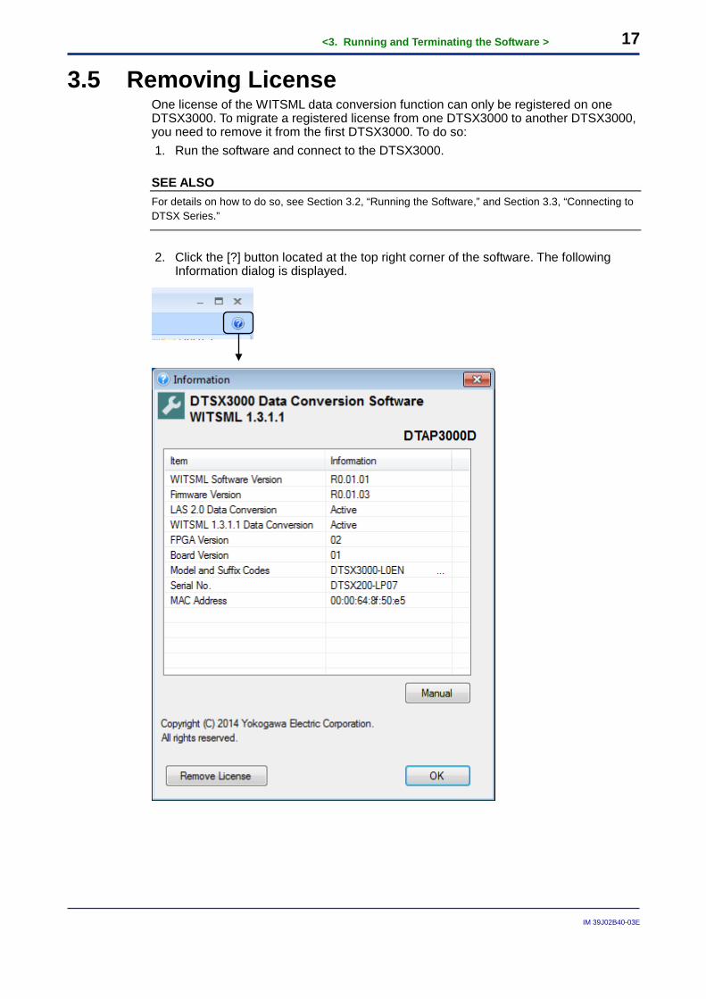
2. Click the [?] button located at the top right corner of the software. The following
Information dialog is displayed.
<3. Running and Terminating the Software > 18
IM 39J02B40-03E
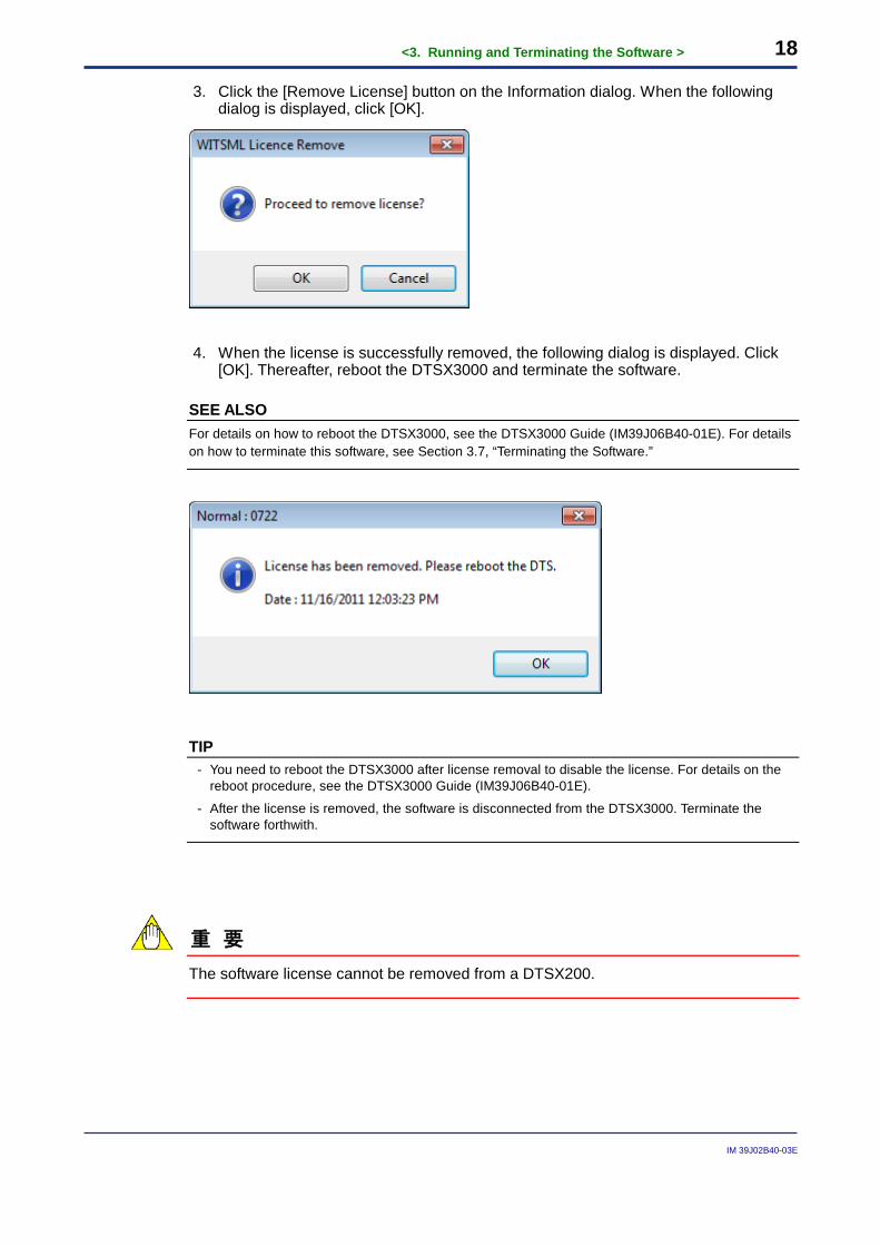
3. Click the [Remove License] button on the Information dialog. When the following dialog is displayed, click [OK].
4. When the license is successfully removed, the following dialog is displayed. Click [OK]. Thereafter, reboot the DTSX3000 and terminate the software.
SEE ALSO For details on how to reboot the DTSX3000, see the DTSX3000 Guide (IM39J06B40-01E). For details on how to terminate this software, see Section 3.7, “Terminating the Software.”
TIP - You need to reboot the DTSX3000 after license removal to disable the license. For details on the
reboot procedure, see the DTSX3000 Guide (IM39J06B40-01E).
- After the license is removed, the software is disconnected from the DTSX3000. Terminate the software forthwith.
重 要
The software license cannot be removed from a DTSX200.
<3. Running and Terminating the Software > 19
IM 39J02B40-03E
3.6 Online and Offline States In online state when the software is connected to the DTSX Series, you can control WITSML file conversion by the DTSX Series, as well as edit settings. On the other hand, in offline state where the software is not connected to the DTSX Series, you can edit settings.
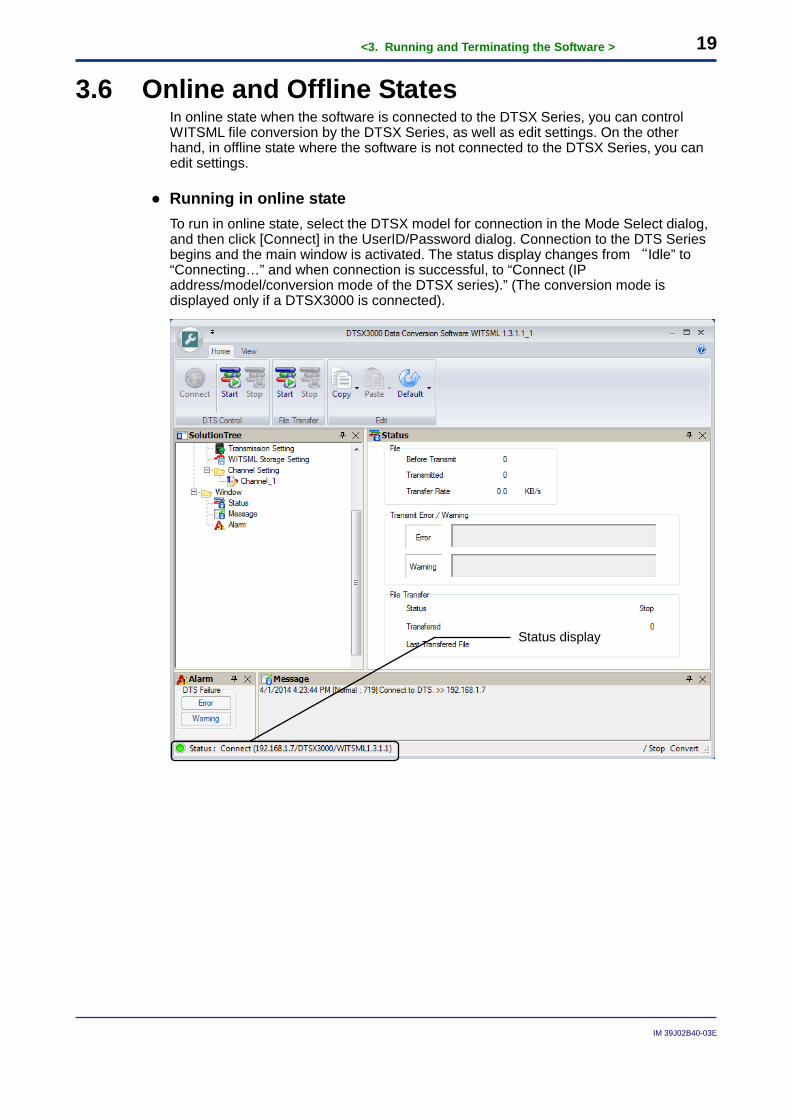
● Running in online state To run in online state, select the DTSX model for connection in the Mode Select dialog, and then click [Connect] in the UserID/Password dialog. Connection to the DTS Series begins and the main window is activated. The status display changes from “Idle” to “Connecting…” and when connection is successful, to “Connect (IP address/model/conversion mode of the DTSX series).” (The conversion mode is displayed only if a DTSX3000 is connected).
Status display
<3. Running and Terminating the Software > 20
IM 39J02B40-03E
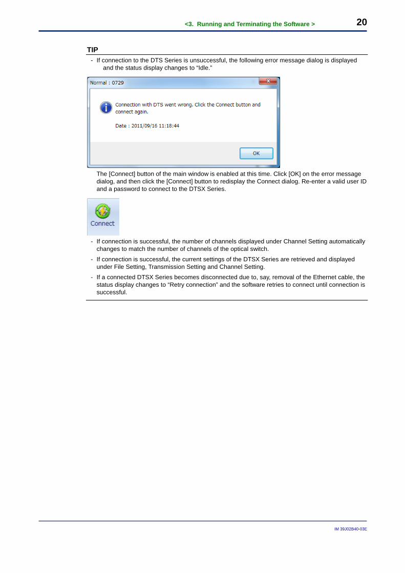
TIP - If connection to the DTS Series is unsuccessful, the following error message dialog is displayed
and the status display changes to “Idle.”
The [Connect] button of the main window is enabled at this time. Click [OK] on the error message
dialog, and then click the [Connect] button to redisplay the Connect dialog. Re-enter a valid user ID and a password to connect to the DTSX Series.
- If connection is successful, the number of channels displayed under Channel Setting automatically
changes to match the number of channels of the optical switch.
- If connection is successful, the current settings of the DTSX Series are retrieved and displayed under File Setting, Transmission Setting and Channel Setting.
- If a connected DTSX Series becomes disconnected due to, say, removal of the Ethernet cable, the status display changes to “Retry connection” and the software retries to connect until connection is successful.
<3. Running and Terminating the Software > 21
IM 39J02B40-03E
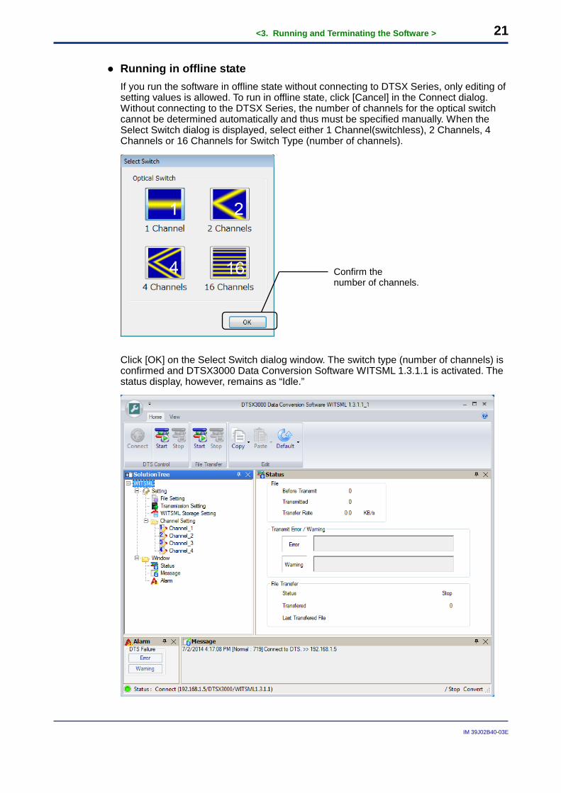
● Running in offline state If you run the software in offline state without connecting to DTSX Series, only editing of setting values is allowed. To run in offline state, click [Cancel] in the Connect dialog. Without connecting to the DTSX Series, the number of channels for the optical switch cannot be determined automatically and thus must be specified manually. When the Select Switch dialog is displayed, select either 1 Channel(switchless), 2 Channels, 4 Channels or 16 Channels for Switch Type (number of channels).
Click [OK] on the Select Switch dialog window. The switch type (number of channels) is confirmed and DTSX3000 Data Conversion Software WITSML 1.3.1.1 is activated. The status display, however, remains as “Idle.”
Confirm the number of channels.
<3. Running and Terminating the Software > 22
IM 39J02B40-03E
TIP - The number of channels displayed on Channel Setting changes automatically to match the number
of channels selected for the optical switch on the Select Switch dialog.
- File Setting, Transmission Setting and Channel Setting display the last confirmed edited settings.
3.7 Terminating the Software
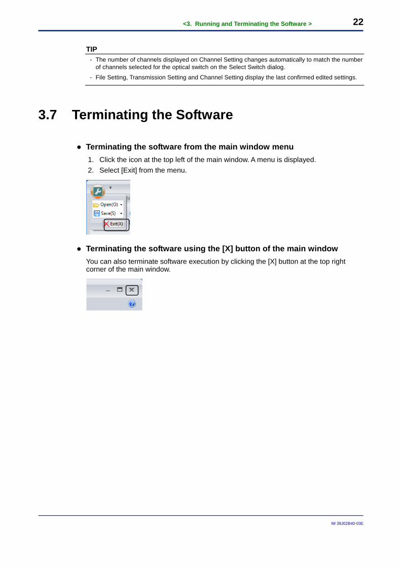
● Terminating the software from the main window menu 1. Click the icon at the top left of the main window. A menu is displayed. 2. Select [Exit] from the menu.
● Terminating the software using the [X] button of the main window You can also terminate software execution by clicking the [X] button at the top right corner of the main window.

<4. Basic Software Operations > 23
IM 39J02B40-03E
Blank Page
<4. Basic Software Operations > 24
IM 39J02B40-03E
4. Basic Software Operations This chapter describes the windows, dialogs and basic operations of the software. This document distinguishes between “windows”, which can be docked to the main window, and “dialogs”, which are displayed as pop-ups of windows.
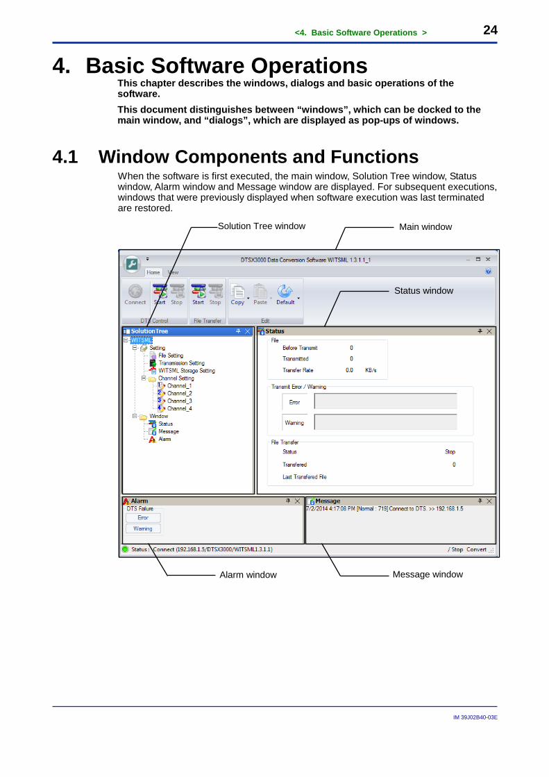
4.1 Window Components and Functions When the software is first executed, the main window, Solution Tree window, Status window, Alarm window and Message window are displayed. For subsequent executions, windows that were previously displayed when software execution was last terminated are restored.
Main window Solution Tree window
Status window
Alarm window Message window
<4. Basic Software Operations > 25
IM 39J02B40-03E
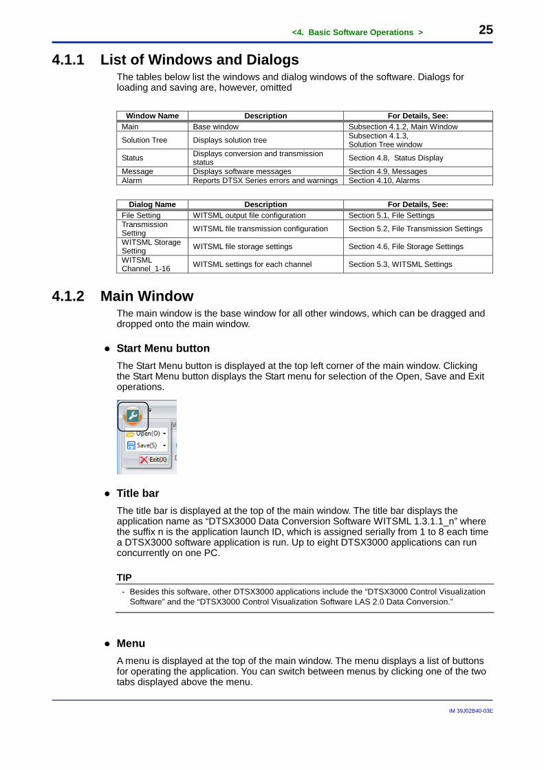
4.1.1 List of Windows and Dialogs The tables below list the windows and dialog windows of the software. Dialogs for loading and saving are, however, omitted
Window Name Description For Details, See: Main Base window Subsection 4.1.2, Main Window
Solution Tree Displays solution tree Subsection 4.1.3, Solution Tree window
Status Displays conversion and transmission status Section 4.8, Status Display
Message Displays software messages Section 4.9, Messages Alarm Reports DTSX Series errors and warnings Section 4.10, Alarms
Dialog Name Description For Details, See:
File Setting WITSML output file configuration Section 5.1, File Settings Transmission Setting WITSML file transmission configuration Section 5.2, File Transmission Settings
WITSML Storage Setting WITSML file storage settings Section 4.6, File Storage Settings
WITSML Channel_1-16 WITSML settings for each channel Section 5.3, WITSML Settings
4.1.2 Main Window The main window is the base window for all other windows, which can be dragged and dropped onto the main window.
● Start Menu button The Start Menu button is displayed at the top left corner of the main window. Clicking the Start Menu button displays the Start menu for selection of the Open, Save and Exit operations.
● Title bar The title bar is displayed at the top of the main window. The title bar displays the application name as “DTSX3000 Data Conversion Software WITSML 1.3.1.1_n” where the suffix n is the application launch ID, which is assigned serially from 1 to 8 each time a DTSX3000 software application is run. Up to eight DTSX3000 applications can run concurrently on one PC.
TIP - Besides this software, other DTSX3000 applications include the “DTSX3000 Control Visualization
Software” and the “DTSX3000 Control Visualization Software LAS 2.0 Data Conversion.”
● Menu A menu is displayed at the top of the main window. The menu displays a list of buttons for operating the application. You can switch between menus by clicking one of the two tabs displayed above the menu.
<4. Basic Software Operations > 26
IM 39J02B40-03E
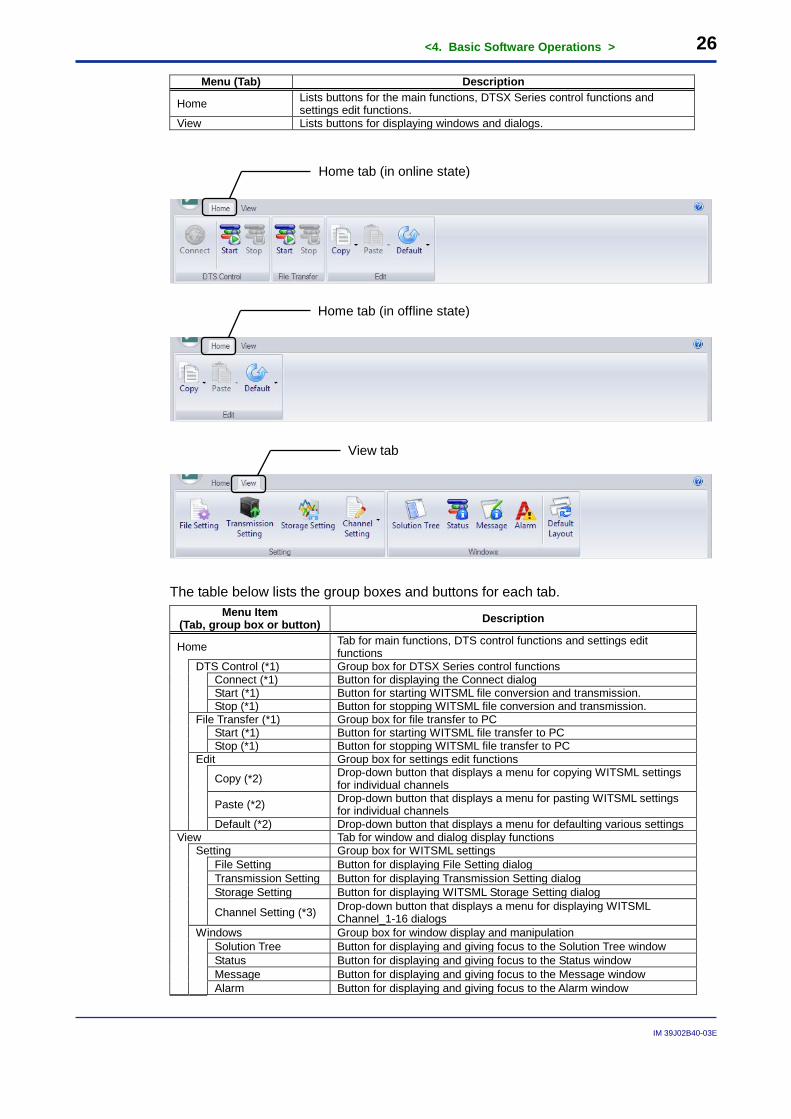
Menu (Tab) Description
Home Lists buttons for the main functions, DTSX Series control functions and settings edit functions.
View Lists buttons for displaying windows and dialogs.
The table below lists the group boxes and buttons for each tab.
Menu Item (Tab, group box or button) Description
Home Tab for main functions, DTS control functions and settings edit functions
DTS Control (*1) Group box for DTSX Series control functions
Connect (*1) Button for displaying the Connect dialog Start (*1) Button for starting WITSML file conversion and transmission. Stop (*1) Button for stopping WITSML file conversion and transmission.
File Transfer (*1) Group box for file transfer to PC
Start (*1) Button for starting WITSML file transfer to PC Stop (*1) Button for stopping WITSML file transfer to PC
Edit Group box for settings edit functions
Copy (*2) Drop-down button that displays a menu for copying WITSML settings for individual channels
Paste (*2) Drop-down button that displays a menu for pasting WITSML settings for individual channels
Default (*2) Drop-down button that displays a menu for defaulting various settings View Tab for window and dialog display functions
Setting Group box for WITSML settings
File Setting Button for displaying File Setting dialog Transmission Setting Button for displaying Transmission Setting dialog Storage Setting Button for displaying WITSML Storage Setting dialog
Channel Setting (*3) Drop-down button that displays a menu for displaying WITSML Channel_1-16 dialogs
Windows Group box for window display and manipulation
Solution Tree Button for displaying and giving focus to the Solution Tree window Status Button for displaying and giving focus to the Status window Message Button for displaying and giving focus to the Message window Alarm Button for displaying and giving focus to the Alarm window
Home tab (in online state)
Home tab (in offline state)
View tab
<4. Basic Software Operations > 27
IM 39J02B40-03E
Default Layout Button for initializing the display positions of windows *1: These items are not displayed in offline state. *2: Clicking the Copy, Paste or Default drop-down button displays a menu of settings for selection. For details, see Section
4.3, "Copying, Pasting and Defaulting Settings." *3: Clicking the Channel Setting drop-down button displays a menu for displaying each WITSML Channel dialog.
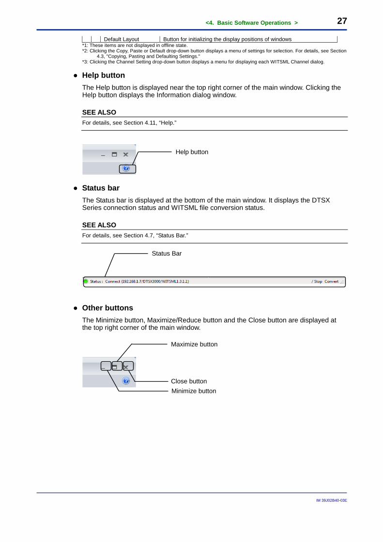
● Help button The Help button is displayed near the top right corner of the main window. Clicking the Help button displays the Information dialog window.
SEE ALSO For details, see Section 4.11, “Help.”
● Status bar The Status bar is displayed at the bottom of the main window. It displays the DTSX Series connection status and WITSML file conversion status.
SEE ALSO For details, see Section 4.7, “Status Bar.”
● Other buttons The Minimize button, Maximize/Reduce button and the Close button are displayed at the top right corner of the main window.
Help button
Close button Minimize button
Maximize button
Status Bar
<4. Basic Software Operations > 28
IM 39J02B40-03E
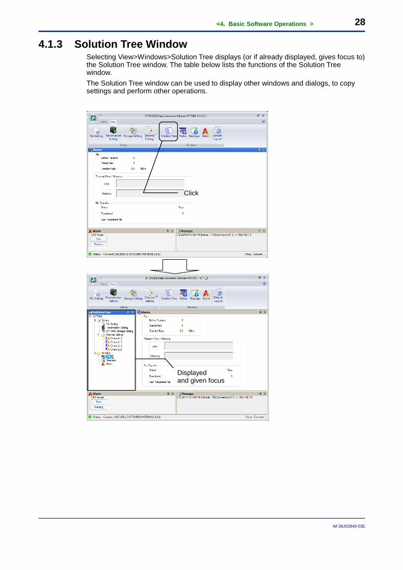
4.1.3 Solution Tree Window Selecting View>Windows>Solution Tree displays (or if already displayed, gives focus to) the Solution Tree window. The table below lists the functions of the Solution Tree window. The Solution Tree window can be used to display other windows and dialogs, to copy settings and perform other operations.
Click
Displayed and given focus
<4. Basic Software Operations > 29
IM 39J02B40-03E
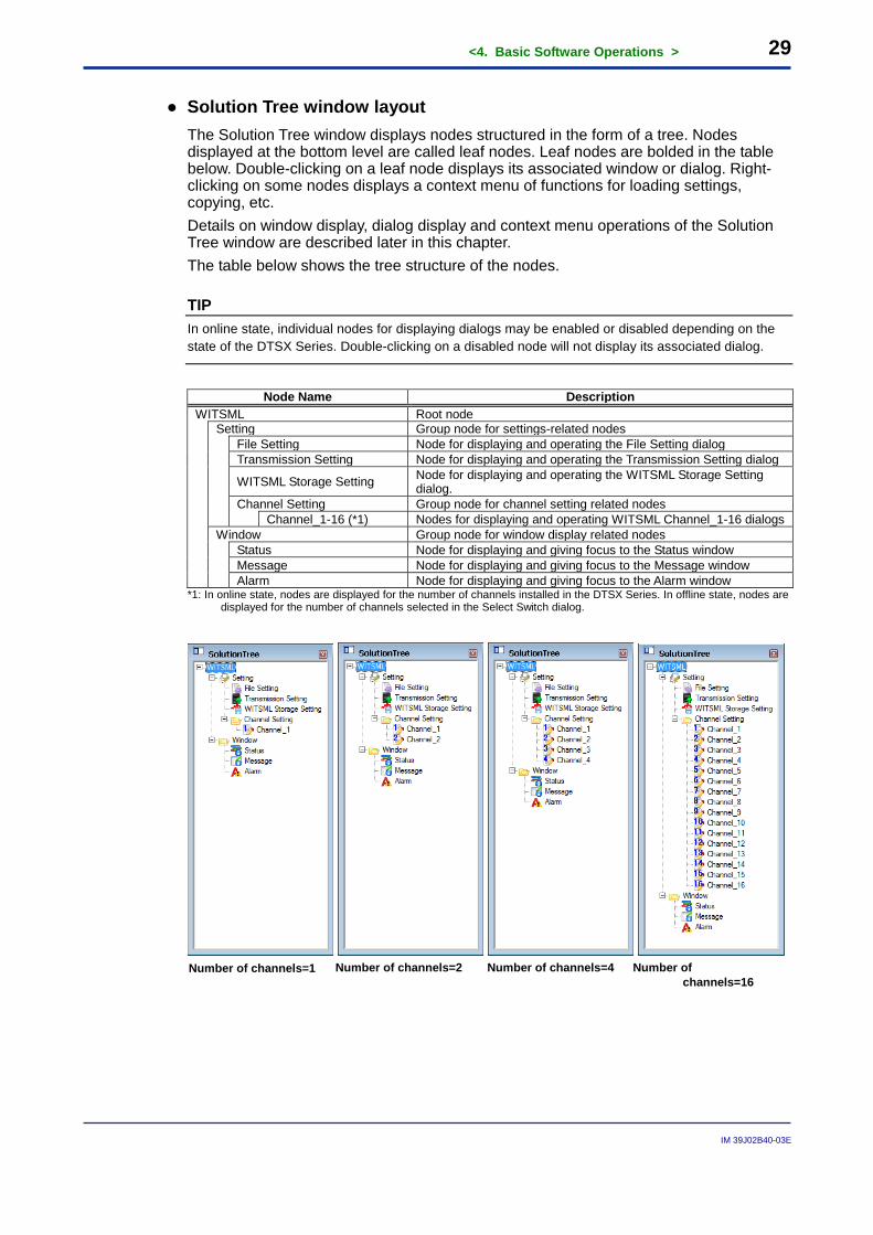
● Solution Tree window layout The Solution Tree window displays nodes structured in the form of a tree. Nodes displayed at the bottom level are called leaf nodes. Leaf nodes are bolded in the table below. Double-clicking on a leaf node displays its associated window or dialog. Right-clicking on some nodes displays a context menu of functions for loading settings, copying, etc. Details on window display, dialog display and context menu operations of the Solution Tree window are described later in this chapter. The table below shows the tree structure of the nodes.
TIP In online state, individual nodes for displaying dialogs may be enabled or disabled depending on the state of the DTSX Series. Double-clicking on a disabled node will not display its associated dialog.
Node Name Description
WITSML Root node
Setting Group node for settings-related nodes
File Setting Node for displaying and operating the File Setting dialog Transmission Setting Node for displaying and operating the Transmission Setting dialog
WITSML Storage Setting Node for displaying and operating the WITSML Storage Setting dialog.
Channel Setting Group node for channel setting related nodes Channel_1-16 (*1) Nodes for displaying and operating WITSML Channel_1-16 dialogs
Window Group node for window display related nodes
Status Node for displaying and giving focus to the Status window Message Node for displaying and giving focus to the Message window Alarm Node for displaying and giving focus to the Alarm window
*1: In online state, nodes are displayed for the number of channels installed in the DTSX Series. In offline state, nodes are displayed for the number of channels selected in the Select Switch dialog.
Number of channels=1 Number of channels=2 Number of channels=4 Number of channels=16
<4. Basic Software Operations > 30
IM 39J02B40-03E
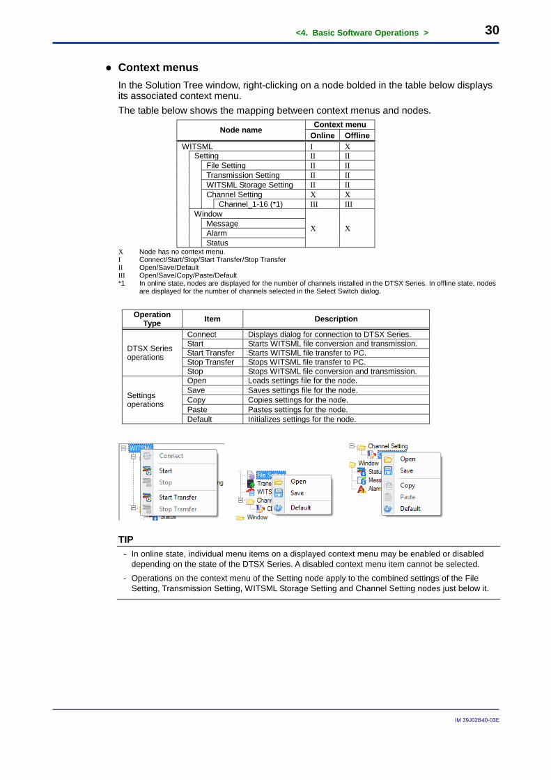
● Context menus In the Solution Tree window, right-clicking on a node bolded in the table below displays its associated context menu. The table below shows the mapping between context menus and nodes.
Node name Context menu Online Offline
WITSML I X
Setting II II
File Setting II II Transmission Setting II II WITSML Storage Setting II II Channel Setting X X Channel_1-16 (*1) III III
Window
X X Message Alarm Status
X Node has no context menu. I Connect/Start/Stop/Start Transfer/Stop Transfer II Open/Save/Default III Open/Save/Copy/Paste/Default *1 In online state, nodes are displayed for the number of channels installed in the DTSX Series. In offline state, nodes
are displayed for the number of channels selected in the Select Switch dialog.
Operation Type Item Description
DTSX Series operations
Connect Displays dialog for connection to DTSX Series. Start Starts WITSML file conversion and transmission. Start Transfer Starts WITSML file transfer to PC. Stop Transfer Stops WITSML file transfer to PC. Stop Stops WITSML file conversion and transmission.
Settings operations
Open Loads settings file for the node. Save Saves settings file for the node. Copy Copies settings for the node. Paste Pastes settings for the node. Default Initializes settings for the node.
TIP - In online state, individual menu items on a displayed context menu may be enabled or disabled
depending on the state of the DTSX Series. A disabled context menu item cannot be selected.
- Operations on the context menu of the Setting node apply to the combined settings of the File Setting, Transmission Setting, WITSML Storage Setting and Channel Setting nodes just below it.
<4. Basic Software Operations > 31
IM 39J02B40-03E
4.2 Loading and Saving Settings Settings specified using the software can be saved to or loaded from a settings file either from the Start menu of the main window or from a context menu in the Solution Tree window.
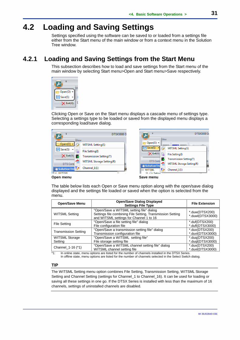
4.2.1 Loading and Saving Settings from the Start Menu This subsection describes how to load and save settings from the Start menu of the main window by selecting Start menu>Open and Start menu>Save respectively.
Clicking Open or Save on the Start menu displays a cascade menu of settings type. Selecting a settings type to be loaded or saved from the displayed menu displays a corresponding load/save dialog.
Open menu Save menu
The table below lists each Open or Save menu option along with the open/save dialog displayed and the settings file loaded or saved when the option is selected from the menu.
Open/Save Menu Open/Save Dialog Displayed Settings File Type File Extension
WITSML Setting "Open/Save a WITSML setting file" dialog Settings file combining File Setting, Transmission Setting and WITSML settings for Channel 1 to 16
*.duw(DTSX200) *.duwl(DTSX3000)
File Setting "Open/Save a file setting file" dialog File configuration file
*.duf(DTSX200) *.dufl(DTSX3000)
Transmission Setting "Open/Save a transmission setting file" dialog Transmission configuration file
*.duv(DTSX200) *.duvl(DTSX3000)
WITSML Storage Setting
"Open/Save a WITSML setting file" File storage setting file
*.duq(DTSX200) *.duql(DTSX3000)
Channel_1-16 (*1) "Open/Save a WITSML channel setting file" dialog WITSML channel setting file
*.dux(DTSX200) *.duxl(DTSX3000)
*1: In online state, menu options are listed for the number of channels installed in the DTSX Series. In offline state, menu options are listed for the number of channels selected in the Select Switch dialog.
TIP The WITSML Setting menu option combines File Setting, Transmission Setting, WITSML Storage Setting and Channel Setting (settings for Channel_1 to Channel_16). It can be used for loading or saving all these settings in one go. If the DTSX Series is installed with less than the maximum of 16 channels, settings of uninstalled channels are disabled.
<4. Basic Software Operations > 32
IM 39J02B40-03E
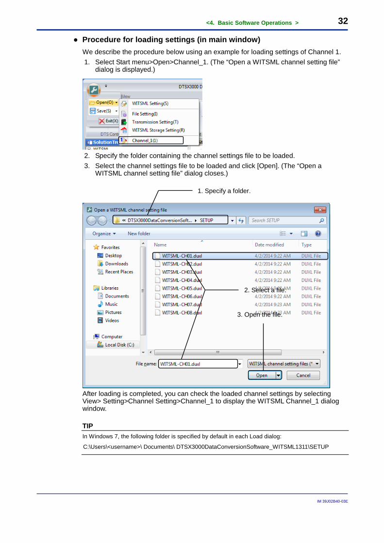
● Procedure for loading settings (in main window) We describe the procedure below using an example for loading settings of Channel 1. 1. Select Start menu>Open>Channel_1. (The “Open a WITSML channel setting file”
dialog is displayed.)
2. Specify the folder containing the channel settings file to be loaded. 3. Select the channel settings file to be loaded and click [Open]. (The “Open a
WITSML channel setting file” dialog closes.)
After loading is completed, you can check the loaded channel settings by selecting View> Setting>Channel Setting>Channel_1 to display the WITSML Channel_1 dialog window.
TIP In Windows 7, the following folder is specified by default in each Load dialog:
C:\Users\<username>\ Documents\ DTSX3000DataConversionSoftware_WITSML1311\SETUP
1. Specify a folder.
2. Select a file.
3. Open the file.
<4. Basic Software Operations > 33
IM 39J02B40-03E
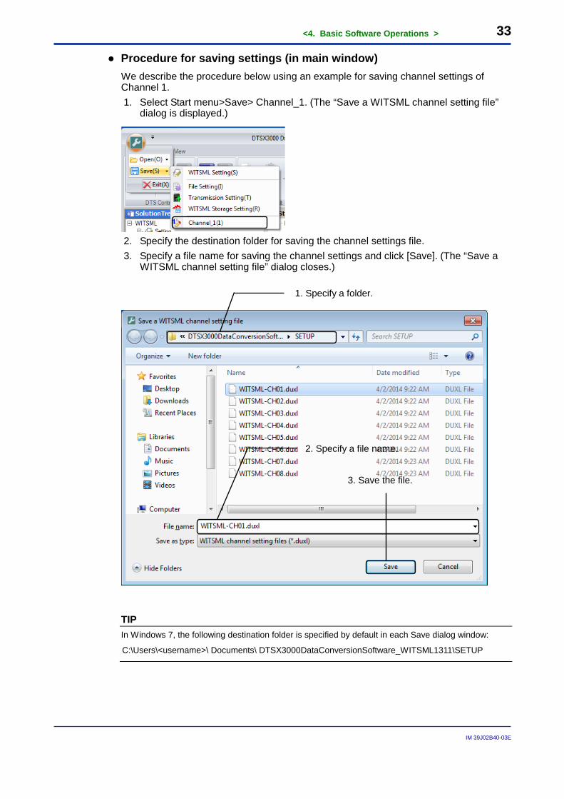
● Procedure for saving settings (in main window) We describe the procedure below using an example for saving channel settings of Channel 1. 1. Select Start menu>Save> Channel_1. (The “Save a WITSML channel setting file”
dialog is displayed.)
2. Specify the destination folder for saving the channel settings file. 3. Specify a file name for saving the channel settings and click [Save]. (The “Save a
WITSML channel setting file” dialog closes.)
TIP In Windows 7, the following destination folder is specified by default in each Save dialog window:
C:\Users\<username>\ Documents\ DTSX3000DataConversionSoftware_WITSML1311\SETUP
1. Specify a folder.
2. Specify a file name.
3. Save the file.
<4. Basic Software Operations > 34
IM 39J02B40-03E
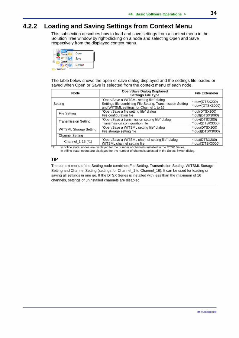
4.2.2 Loading and Saving Settings from Context Menu This subsection describes how to load and save settings from a context menu in the Solution Tree window by right-clicking on a node and selecting Open and Save respectively from the displayed context menu.
The table below shows the open or save dialog displayed and the settings file loaded or saved when Open or Save is selected from the context menu of each node.
Node Open/Save Dialog Displayed Settings File Type File Extension
Setting "Open/Save a WITSML setting file" dialog Settings file combining File Setting, Transmission Setting and WITSML settings for Channel 1 to 16
*.duw(DTSX200) *.duwl(DTSX3000)
File Setting "Open/Save a file setting file" dialog File configuration file
*.duf(DTSX200) *.dufl(DTSX3000)
Transmission Setting "Open/Save a transmission setting file" dialog Transmission configuration file
*.duv(DTSX200) *.duvl(DTSX3000)
WITSML Storage Setting "Open/Save a WITSML setting file" dialog File storage setting file
*.duq(DTSX200) *.duql(DTSX3000)
Channel Setting
Channel_1-16 (*1) "Open/Save a WITSML channel setting file" dialog WITSML channel setting file
*.dux(DTSX200) *.duxl(DTSX3000)
*1: In online state, nodes are displayed for the number of channels installed in the DTSX Series. In offline state, nodes are displayed for the number of channels selected in the Select Switch dialog.
TIP The context menu of the Setting node combines File Setting, Transmission Setting, WITSML Storage Setting and Channel Setting (settings for Channel_1 to Channel_16). It can be used for loading or saving all settings in one go. If the DTSX Series is installed with less than the maximum of 16 channels, settings of uninstalled channels are disabled.
<4. Basic Software Operations > 35
IM 39J02B40-03E
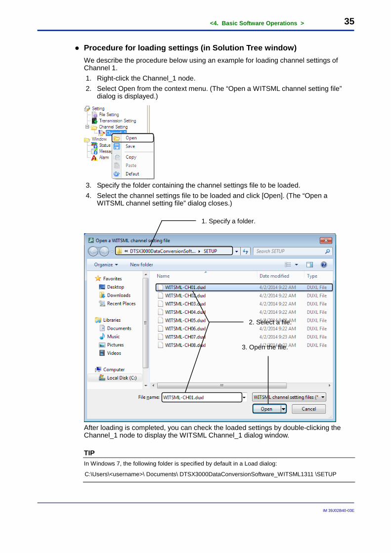
● Procedure for loading settings (in Solution Tree window) We describe the procedure below using an example for loading channel settings of Channel 1. 1. Right-click the Channel_1 node. 2. Select Open from the context menu. (The “Open a WITSML channel setting file”
dialog is displayed.)
3. Specify the folder containing the channel settings file to be loaded. 4. Select the channel settings file to be loaded and click [Open]. (The “Open a
WITSML channel setting file” dialog closes.)
After loading is completed, you can check the loaded settings by double-clicking the Channel_1 node to display the WITSML Channel_1 dialog window.
TIP In Windows 7, the following folder is specified by default in a Load dialog:
C:\Users\<username>\ Documents\ DTSX3000DataConversionSoftware_WITSML1311 \SETUP
1. Specify a folder.
2. Select a file.
3. Open the file.
<4. Basic Software Operations > 36
IM 39J02B40-03E
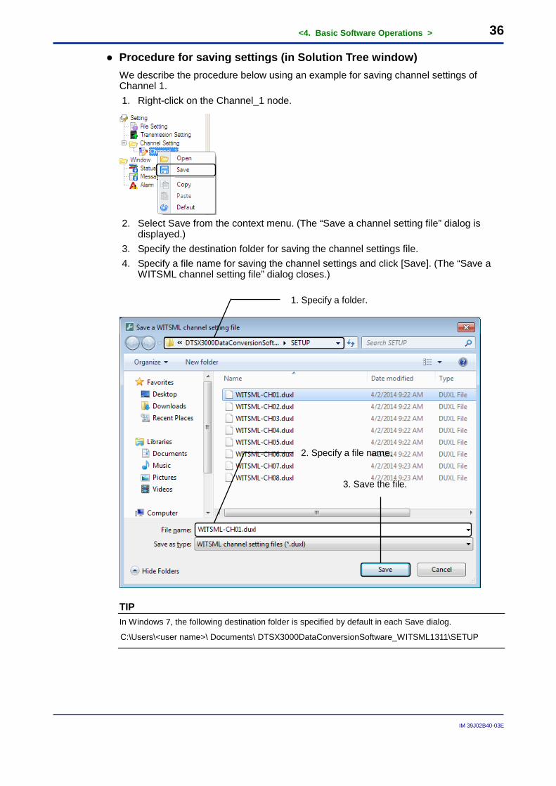
● Procedure for saving settings (in Solution Tree window) We describe the procedure below using an example for saving channel settings of Channel 1. 1. Right-click on the Channel_1 node.
2. Select Save from the context menu. (The “Save a channel setting file” dialog is
displayed.) 3. Specify the destination folder for saving the channel settings file. 4. Specify a file name for saving the channel settings and click [Save]. (The “Save a
WITSML channel setting file” dialog closes.)
TIP In Windows 7, the following destination folder is specified by default in each Save dialog.
C:\Users\<user name>\ Documents\ DTSX3000DataConversionSoftware_WITSML1311\SETUP
1. Specify a folder.
2. Specify a file name.
3. Save the file.
<4. Basic Software Operations > 37
IM 39J02B40-03E
4.3 Copying, Pasting and Defaulting Settings You can copy, paste and initialize (set to default values) WITSML channel settings either from the menu of the main window or from a context menu in the Solution Tree window.
TIP - You must perform a copy operation before a paste operation.
- A copy operation overwrites previously copied values.
- Pasting and defaulting is not allowed during conversion or disconnection in online state.
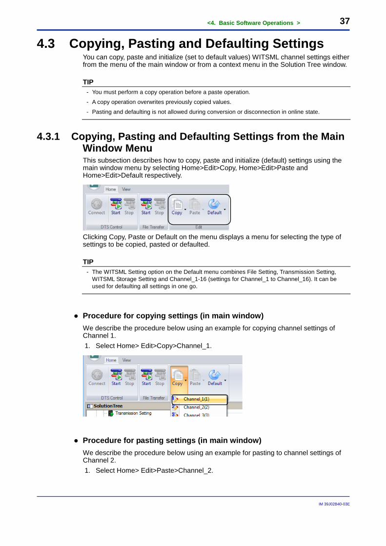
4.3.1 Copying, Pasting and Defaulting Settings from the Main Window Menu This subsection describes how to copy, paste and initialize (default) settings using the main window menu by selecting Home>Edit>Copy, Home>Edit>Paste and Home>Edit>Default respectively.
Clicking Copy, Paste or Default on the menu displays a menu for selecting the type of settings to be copied, pasted or defaulted.
TIP - The WITSML Setting option on the Default menu combines File Setting, Transmission Setting,
WITSML Storage Setting and Channel_1-16 (settings for Channel_1 to Channel_16). It can be used for defaulting all settings in one go.
● Procedure for copying settings (in main window) We describe the procedure below using an example for copying channel settings of Channel 1. 1. Select Home> Edit>Copy>Channel_1.
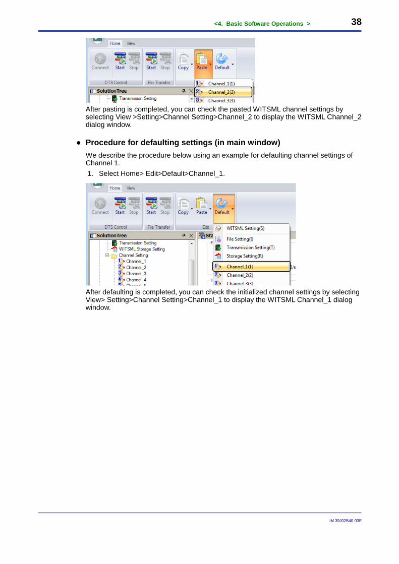
● Procedure for pasting settings (in main window) We describe the procedure below using an example for pasting to channel settings of Channel 2. 1. Select Home> Edit>Paste>Channel_2.
<4. Basic Software Operations > 38
IM 39J02B40-03E
After pasting is completed, you can check the pasted WITSML channel settings by selecting View >Setting>Channel Setting>Channel_2 to display the WITSML Channel_2 dialog window.
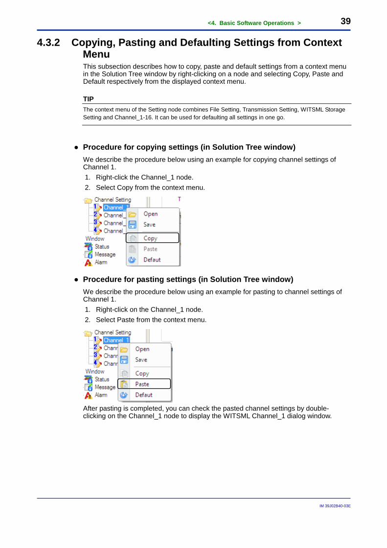
● Procedure for defaulting settings (in main window) We describe the procedure below using an example for defaulting channel settings of Channel 1. 1. Select Home> Edit>Default>Channel_1.
After defaulting is completed, you can check the initialized channel settings by selecting View> Setting>Channel Setting>Channel_1 to display the WITSML Channel_1 dialog window.
<4. Basic Software Operations > 39
IM 39J02B40-03E
4.3.2 Copying, Pasting and Defaulting Settings from Context Menu This subsection describes how to copy, paste and default settings from a context menu in the Solution Tree window by right-clicking on a node and selecting Copy, Paste and Default respectively from the displayed context menu.
TIP The context menu of the Setting node combines File Setting, Transmission Setting, WITSML Storage Setting and Channel_1-16. It can be used for defaulting all settings in one go.
● Procedure for copying settings (in Solution Tree window) We describe the procedure below using an example for copying channel settings of Channel 1. 1. Right-click the Channel_1 node. 2. Select Copy from the context menu.
● Procedure for pasting settings (in Solution Tree window) We describe the procedure below using an example for pasting to channel settings of Channel 1. 1. Right-click on the Channel_1 node. 2. Select Paste from the context menu.
After pasting is completed, you can check the pasted channel settings by double-clicking on the Channel_1 node to display the WITSML Channel_1 dialog window.
<4. Basic Software Operations > 40
IM 39J02B40-03E
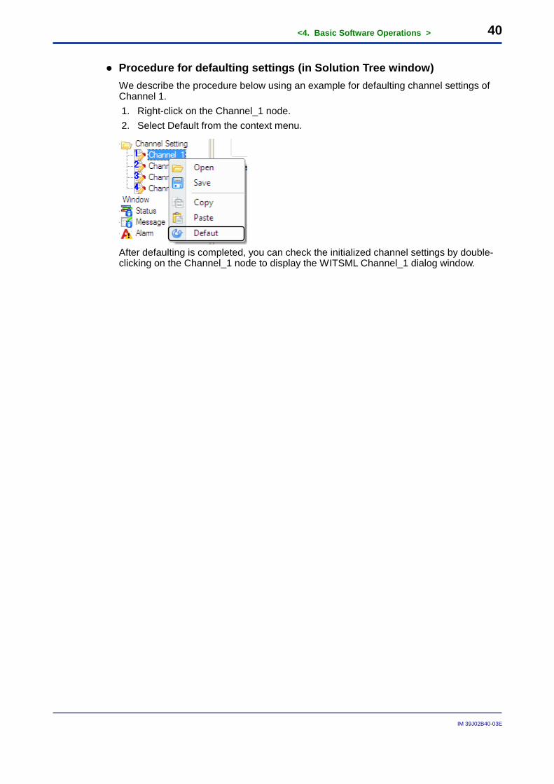
● Procedure for defaulting settings (in Solution Tree window) We describe the procedure below using an example for defaulting channel settings of Channel 1. 1. Right-click on the Channel_1 node. 2. Select Default from the context menu.
After defaulting is completed, you can check the initialized channel settings by double-clicking on the Channel_1 node to display the WITSML Channel_1 dialog window.
<4. Basic Software Operations > 41
IM 39J02B40-03E
4.4 Displaying Windows and Dialogs This section describes how to display windows and dialogs, as well as basic window operations. Windows and dialogs can be displayed from the menu of the main window or from a node in the Solution Tree window. A window or dialog can be displayed by clicking on its associated menu button in the main window. If the window is already displayed, it is given focus. A window or dialog can also be displayed by double-clicking on its associated node in the Solution Tree window. If the window is already displayed, it is given focus.
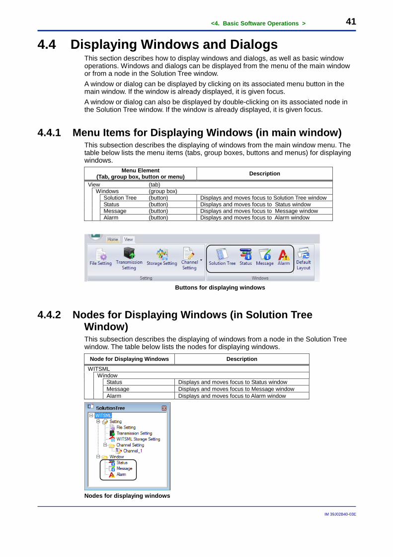
4.4.1 Menu Items for Displaying Windows (in main window) This subsection describes the displaying of windows from the main window menu. The table below lists the menu items (tabs, group boxes, buttons and menus) for displaying windows.
Menu Element (Tab, group box, button or menu) Description
View (tab)
Windows (group box)
Solution Tree (button) Displays and moves focus to Solution Tree window Status (button) Displays and moves focus to Status window Message (button) Displays and moves focus to Message window Alarm (button) Displays and moves focus to Alarm window
Buttons for displaying windows
4.4.2 Nodes for Displaying Windows (in Solution Tree Window) This subsection describes the displaying of windows from a node in the Solution Tree window. The table below lists the nodes for displaying windows.
Node for Displaying Windows Description
WITSML Window
Status Displays and moves focus to Status window Message Displays and moves focus to Message window Alarm Displays and moves focus to Alarm window
Nodes for displaying windows
<4. Basic Software Operations > 42
IM 39J02B40-03E
4.4.3 Window Operations This subsection describes basic window operations.
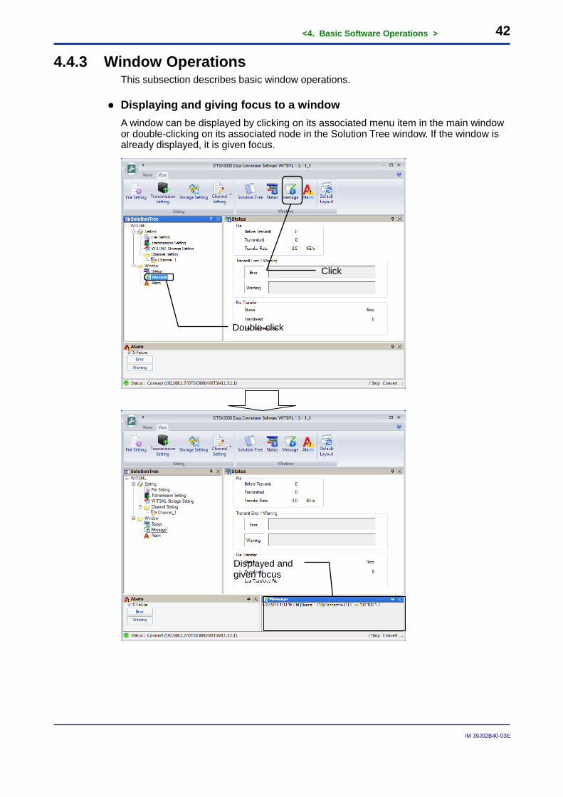
● Displaying and giving focus to a window A window can be displayed by clicking on its associated menu item in the main window or double-clicking on its associated node in the Solution Tree window. If the window is already displayed, it is given focus.
Click
Double-click
Displayed and given focus
<4. Basic Software Operations > 43
IM 39J02B40-03E
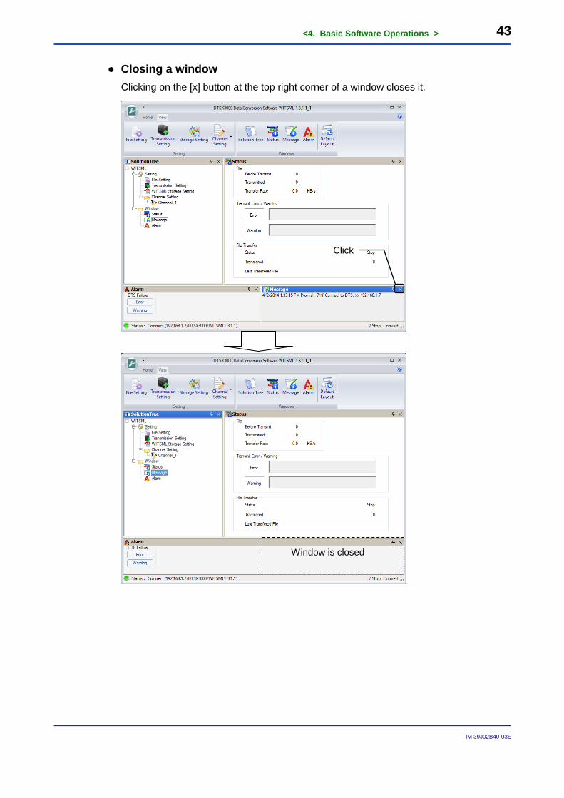
● Closing a window Clicking on the [x] button at the top right corner of a window closes it.
Window is closed
Click
<4. Basic Software Operations > 44
IM 39J02B40-03E
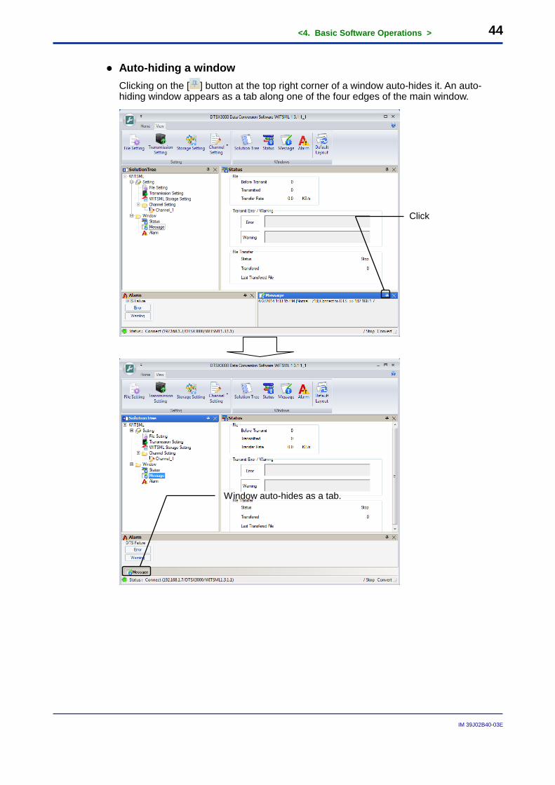
● Auto-hiding a window Clicking on the [ ] button at the top right corner of a window auto-hides it. An auto-hiding window appears as a tab along one of the four edges of the main window.
Click
Window auto-hides as a tab.
<4. Basic Software Operations > 45
IM 39J02B40-03E
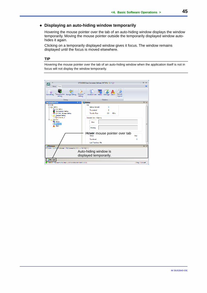
● Displaying an auto-hiding window temporarily Hovering the mouse pointer over the tab of an auto-hiding window displays the window temporarily. Moving the mouse pointer outside the temporarily displayed window auto-hides it again. Clicking on a temporarily displayed window gives it focus. The window remains displayed until the focus is moved elsewhere.
TIP Hovering the mouse pointer over the tab of an auto-hiding window when the application itself is not in focus will not display the window temporarily.
Hover mouse pointer over tab
Auto-hiding window is displayed temporarily.
<4. Basic Software Operations > 46
IM 39J02B40-03E
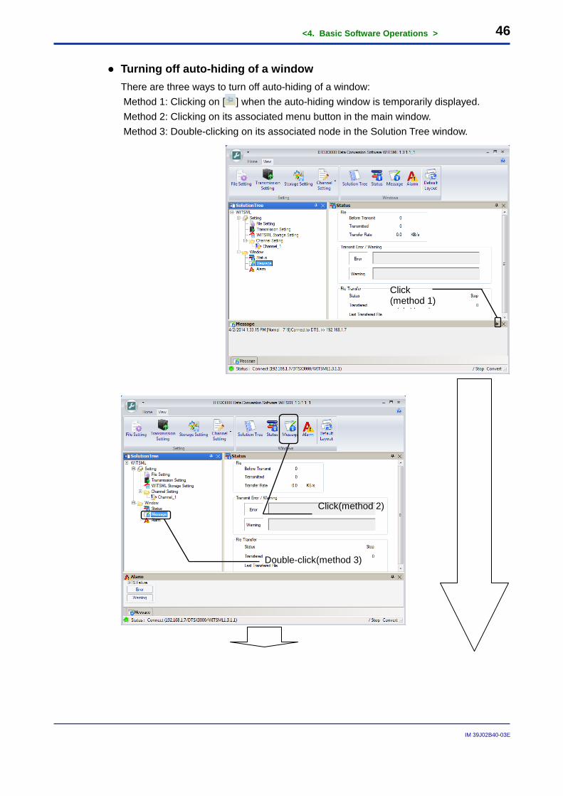
● Turning off auto-hiding of a window There are three ways to turn off auto-hiding of a window: Method 1: Clicking on [ ] when the auto-hiding window is temporarily displayed. Method 2: Clicking on its associated menu button in the main window. Method 3: Double-clicking on its associated node in the Solution Tree window.
Click (method 1) (方法 )
Click(method 2)
Double-click(method 3)
<4. Basic Software Operations > 47
IM 39J02B40-03E
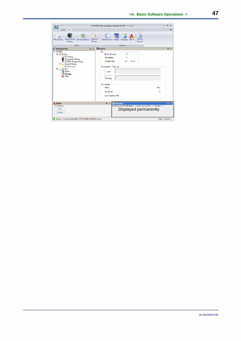
Displayed permanently
<4. Basic Software Operations > 48
IM 39J02B40-03E
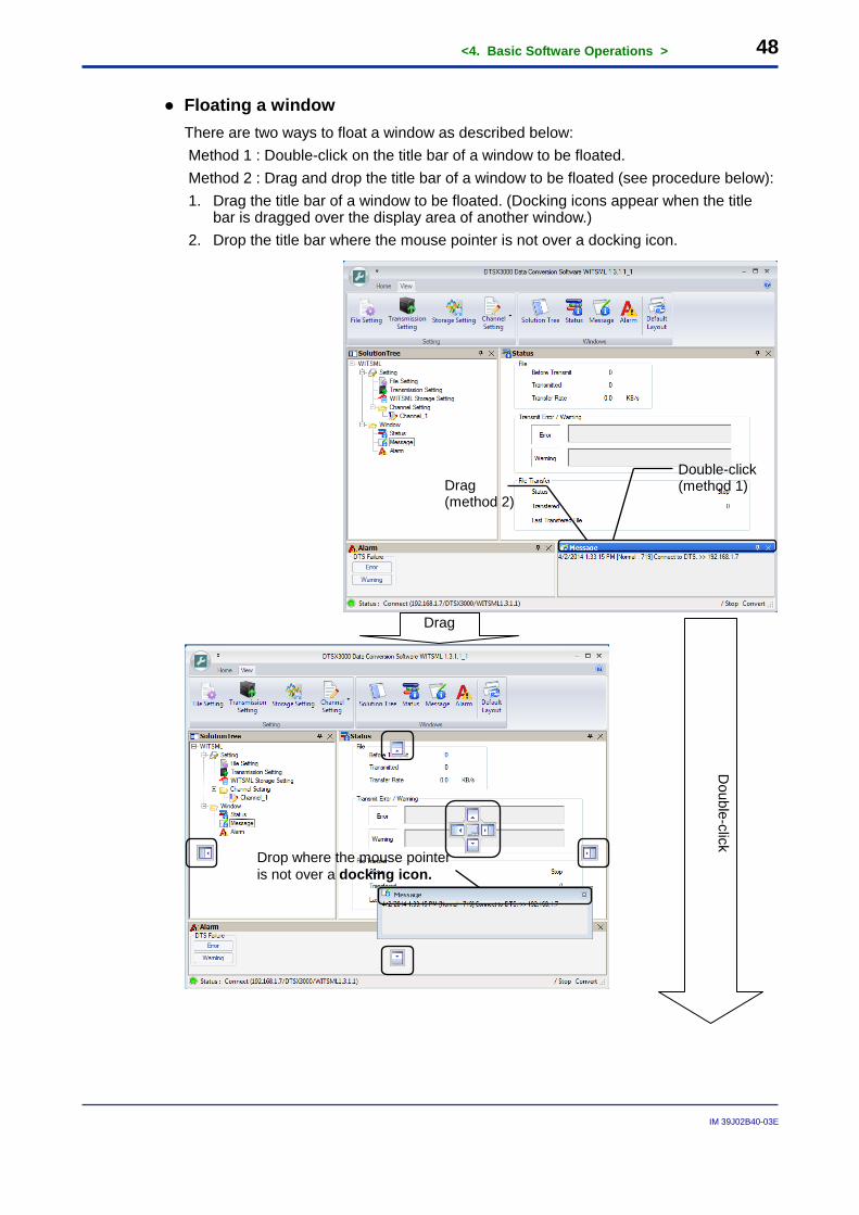
● Floating a window There are two ways to float a window as described below: Method 1 : Double-click on the title bar of a window to be floated. Method 2 : Drag and drop the title bar of a window to be floated (see procedure below): 1. Drag the title bar of a window to be floated. (Docking icons appear when the title
bar is dragged over the display area of another window.) 2. Drop the title bar where the mouse pointer is not over a docking icon.
Drag
Double-click
Double-click (method 1) Drag
(method 2)
Drop where the mouse pointer is not over a docking icon.
<4. Basic Software Operations > 49
IM 39J02B40-03E
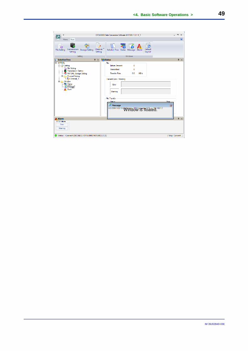
Window is floated.
<4. Basic Software Operations > 50
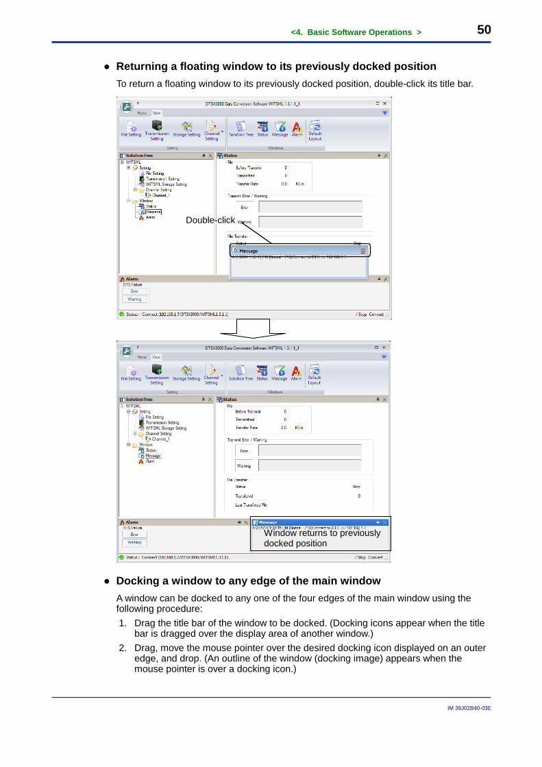
IM 39J02B40-03E
● Returning a floating window to its previously docked position To return a floating window to its previously docked position, double-click its title bar.
● Docking a window to any edge of the main window A window can be docked to any one of the four edges of the main window using the following procedure: 1. Drag the title bar of the window to be docked. (Docking icons appear when the title
bar is dragged over the display area of another window.) 2. Drag, move the mouse pointer over the desired docking icon displayed on an outer
edge, and drop. (An outline of the window (docking image) appears when the mouse pointer is over a docking icon.)
Window returns to previously docked position
Double-click
<4. Basic Software Operations > 51
IM 39J02B40-03E
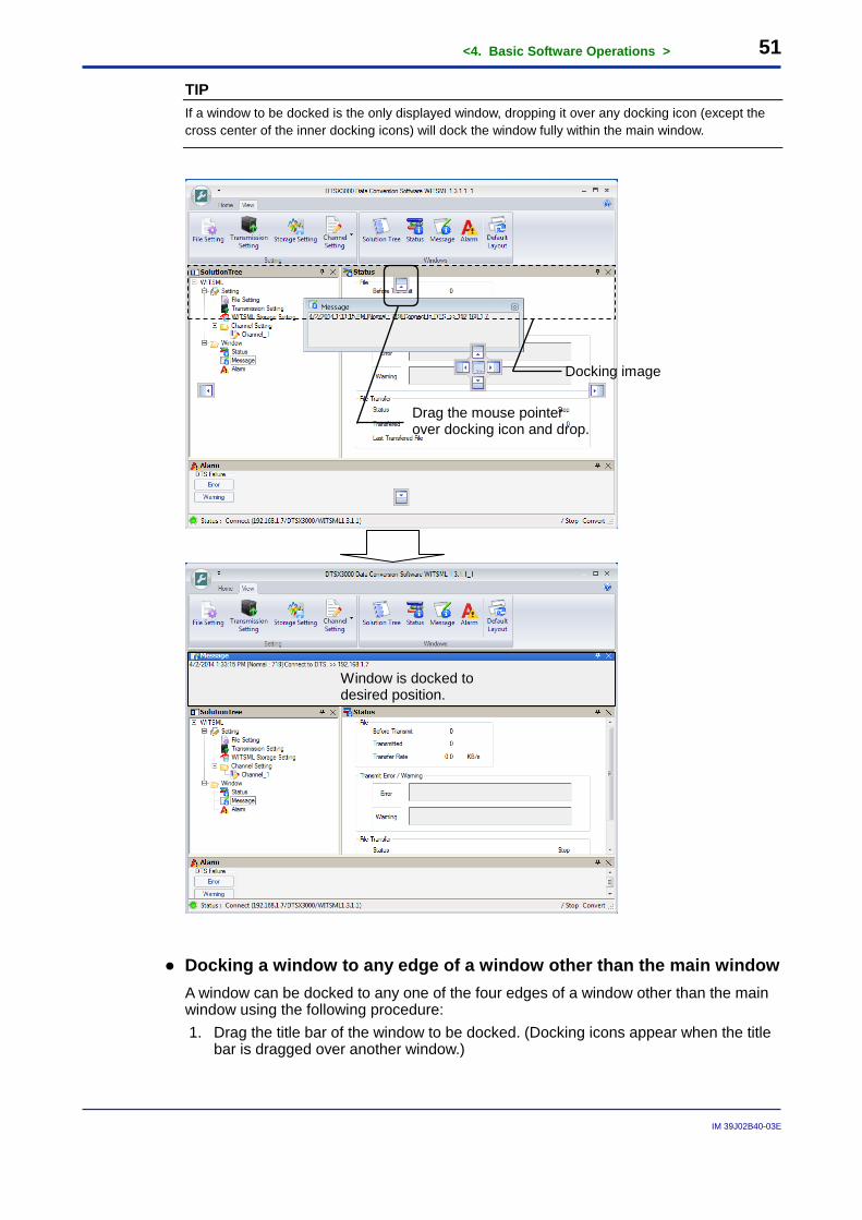
TIP If a window to be docked is the only displayed window, dropping it over any docking icon (except the cross center of the inner docking icons) will dock the window fully within the main window.
● Docking a window to any edge of a window other than the main window A window can be docked to any one of the four edges of a window other than the main window using the following procedure: 1. Drag the title bar of the window to be docked. (Docking icons appear when the title
bar is dragged over another window.)
Window is docked to desired position.
Drag the mouse pointer over docking icon and drop.
Docking image
<4. Basic Software Operations > 52
IM 39J02B40-03E
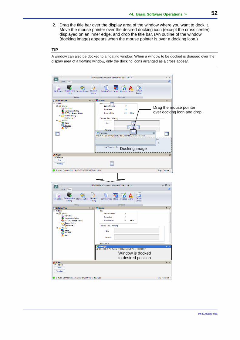
2. Drag the title bar over the display area of the window where you want to dock it. Move the mouse pointer over the desired docking icon (except the cross center) displayed on an inner edge, and drop the title bar. (An outline of the window (docking image) appears when the mouse pointer is over a docking icon.)
TIP A window can also be docked to a floating window. When a window to be docked is dragged over the display area of a floating window, only the docking icons arranged as a cross appear.
Window is docked to desired position
Drag the mouse pointer over docking icon and drop.
Docking image
<4. Basic Software Operations > 53
IM 39J02B40-03E
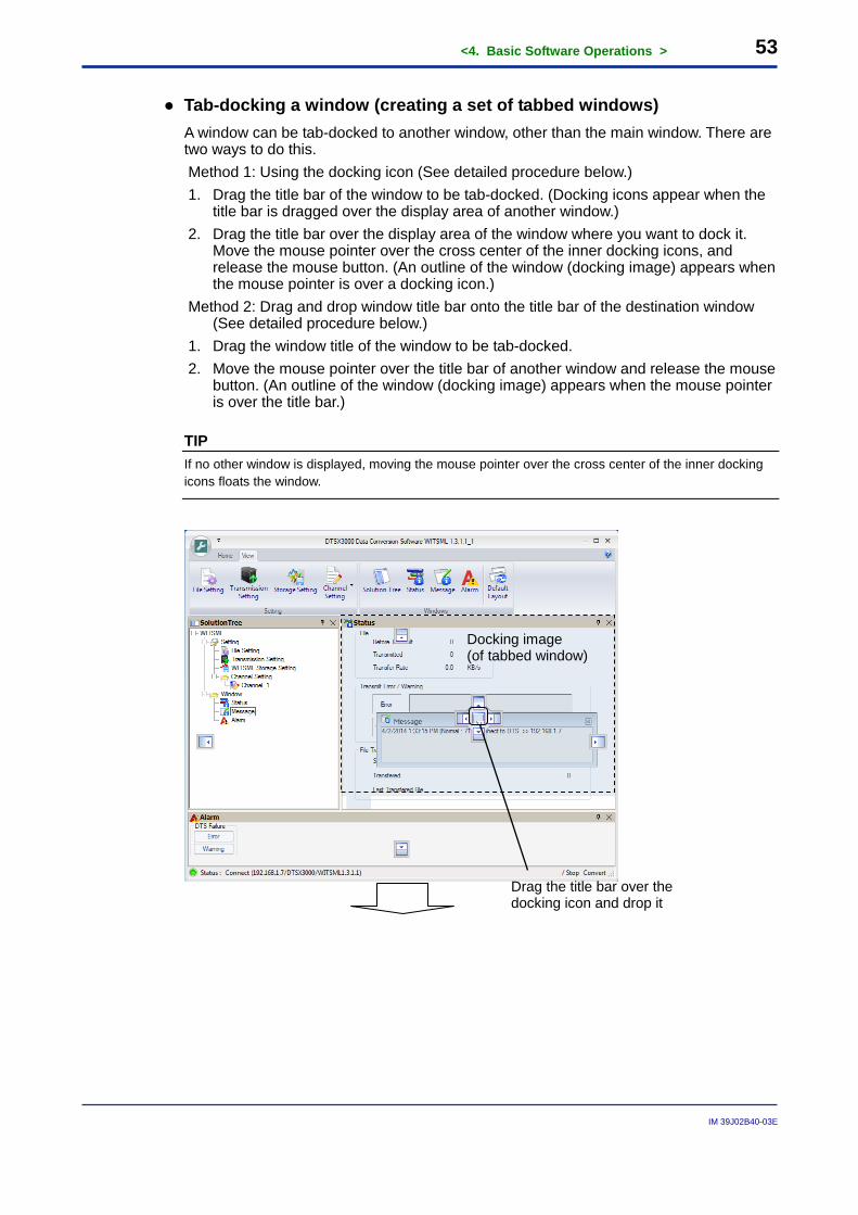
● Tab-docking a window (creating a set of tabbed windows) A window can be tab-docked to another window, other than the main window. There are two ways to do this. Method 1: Using the docking icon (See detailed procedure below.) 1. Drag the title bar of the window to be tab-docked. (Docking icons appear when the
title bar is dragged over the display area of another window.) 2. Drag the title bar over the display area of the window where you want to dock it.
Move the mouse pointer over the cross center of the inner docking icons, and release the mouse button. (An outline of the window (docking image) appears when the mouse pointer is over a docking icon.)
Method 2: Drag and drop window title bar onto the title bar of the destination window (See detailed procedure below.)
1. Drag the window title of the window to be tab-docked. 2. Move the mouse pointer over the title bar of another window and release the mouse
button. (An outline of the window (docking image) appears when the mouse pointer is over the title bar.)
TIP If no other window is displayed, moving the mouse pointer over the cross center of the inner docking icons floats the window.
Drag the title bar over the
docking icon and drop it
Docking image (of tabbed window)
<4. Basic Software Operations > 54
IM 39J02B40-03E
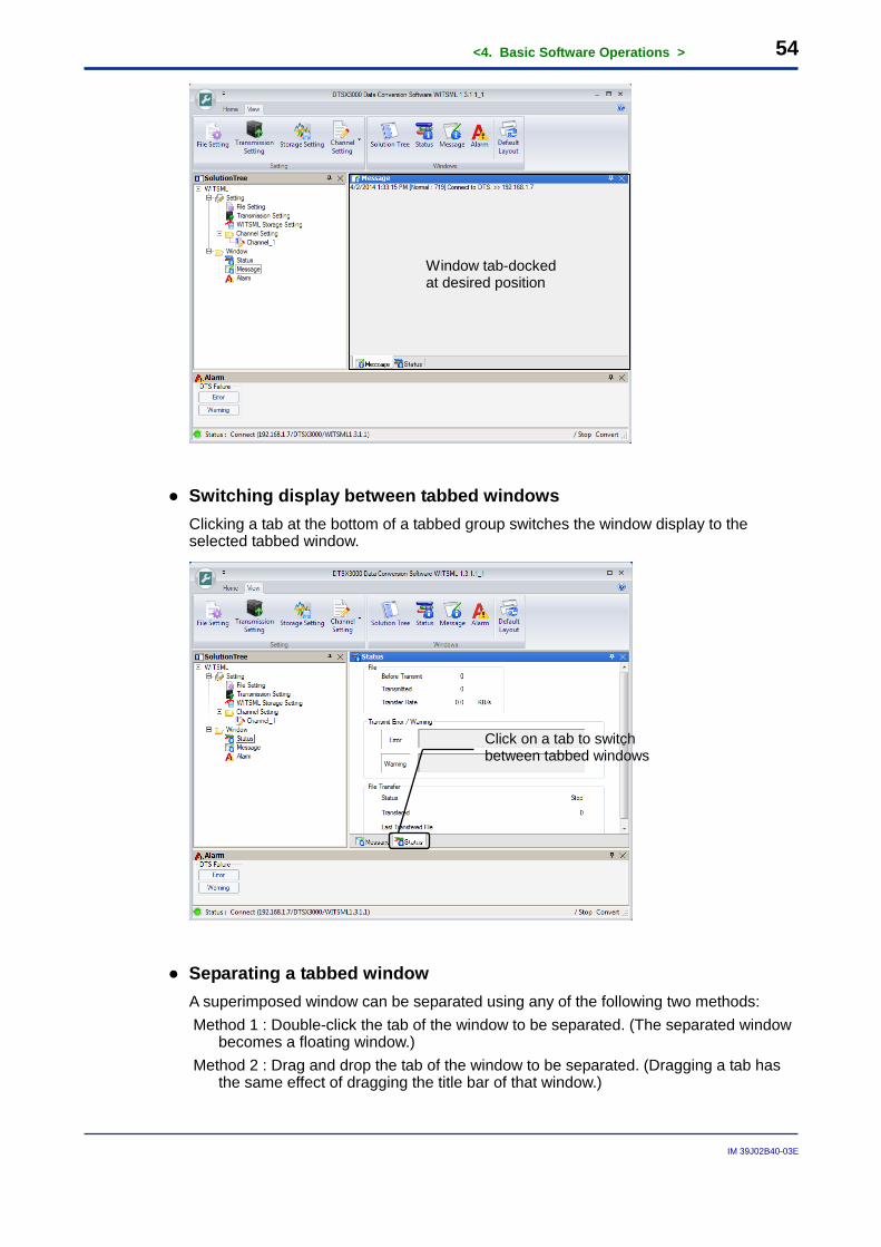
● Switching display between tabbed windows Clicking a tab at the bottom of a tabbed group switches the window display to the selected tabbed window.
● Separating a tabbed window A superimposed window can be separated using any of the following two methods: Method 1 : Double-click the tab of the window to be separated. (The separated window
becomes a floating window.) Method 2 : Drag and drop the tab of the window to be separated. (Dragging a tab has
the same effect of dragging the title bar of that window.)
Window tab-docked at desired position
Click on a tab to switch between tabbed windows
<4. Basic Software Operations > 55
IM 39J02B40-03E
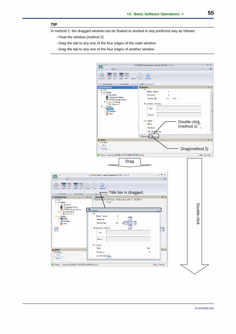
TIP In method 2, the dragged window can be floated or docked in any preferred way as follows:
- Float the window (method 2)
- Drag the tab to any one of the four edges of the main window
- Drag the tab to any one of the four edges of another window
Double-click (method 1)
Drag(method 2)
Drag
Double-click
Title bar is dragged.
<4. Basic Software Operations > 56
IM 39J02B40-03E
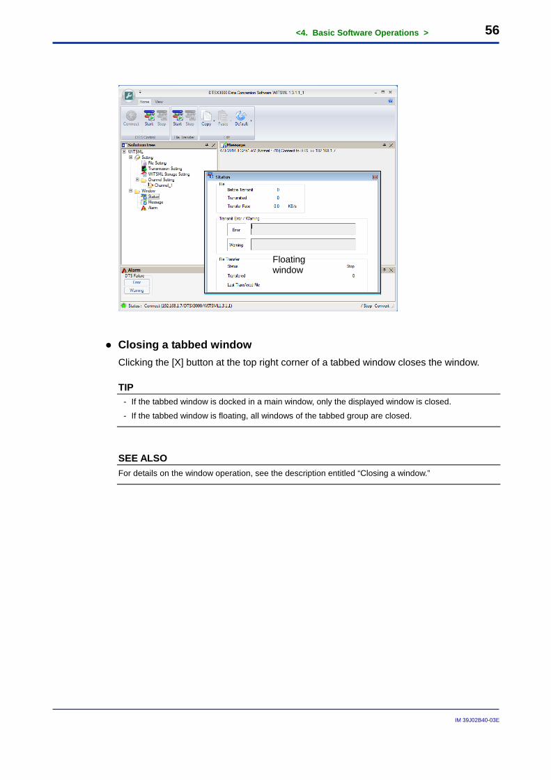
● Closing a tabbed window Clicking the [X] button at the top right corner of a tabbed window closes the window.
TIP - If the tabbed window is docked in a main window, only the displayed window is closed.
- If the tabbed window is floating, all windows of the tabbed group are closed.
SEE ALSO For details on the window operation, see the description entitled “Closing a window.”
Floating window
<4. Basic Software Operations > 57
IM 39J02B40-03E
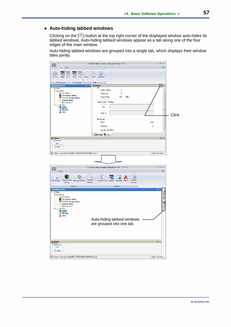
● Auto-hiding tabbed windows Clicking on the [ ] button at the top right corner of the displayed window auto-hides its tabbed windows. Auto-hiding tabbed windows appear as a tab along one of the four edges of the main window. Auto-hiding tabbed windows are grouped into a single tab, which displays their window titles jointly.
Auto-hiding tabbed windows are grouped into one tab.
Click
<4. Basic Software Operations > 58
IM 39J02B40-03E
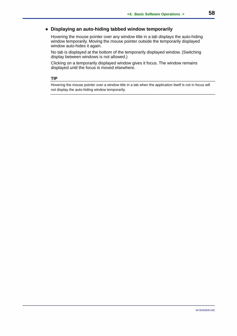
● Displaying an auto-hiding tabbed window temporarily Hovering the mouse pointer over any window title in a tab displays the auto-hiding window temporarily. Moving the mouse pointer outside the temporarily displayed window auto-hides it again. No tab is displayed at the bottom of the temporarily displayed window. (Switching display between windows is not allowed.) Clicking on a temporarily displayed window gives it focus. The window remains displayed until the focus is moved elsewhere.
TIP Hovering the mouse pointer over a window title in a tab when the application itself is not in focus will not display the auto-hiding window temporarily.
<4. Basic Software Operations > 59
IM 39J02B40-03E
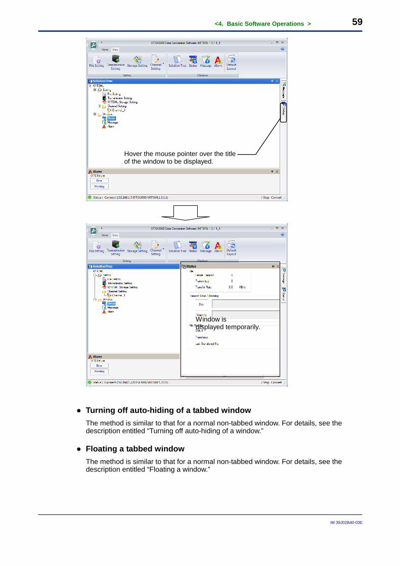
● Turning off auto-hiding of a tabbed window The method is similar to that for a normal non-tabbed window. For details, see the description entitled “Turning off auto-hiding of a window.”
● Floating a tabbed window The method is similar to that for a normal non-tabbed window. For details, see the description entitled “Floating a window.”
Window is displayed temporarily.
Hover the mouse pointer over the title of the window to be displayed.
<4. Basic Software Operations > 60
IM 39J02B40-03E
● Returning a floating tabbed window to its previously docked position The method is similar to that for a normal non-tabbed window. For details, see the description entitled “Returning a floating window to its previously docked position.”
● Docking a tabbed window to any edge of the main window The method is similar to that for a normal non-tabbed window. For details, see the description entitled “Docking a window to any edge of the main window.”
● Docking a tabbed window to any edge of a window other than the main window The method is similar to that for a normal non-tabbed window. For details, see the description entitled “Docking a window to any edge of a window other than the main window.”
<4. Basic Software Operations > 61
IM 39J02B40-03E
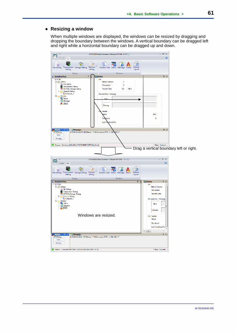
● Resizing a window When multiple windows are displayed, the windows can be resized by dragging and dropping the boundary between the windows. A vertical boundary can be dragged left and right while a horizontal boundary can be dragged up and down.
Drag a vertical boundary left or right.
Windows are resized.
<4. Basic Software Operations > 62
IM 39J02B40-03E
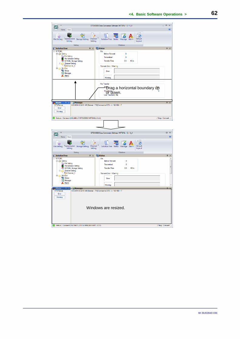
Drag a horizontal boundary up or down.
Windows are resized.
<4. Basic Software Operations > 63
IM 39J02B40-03E
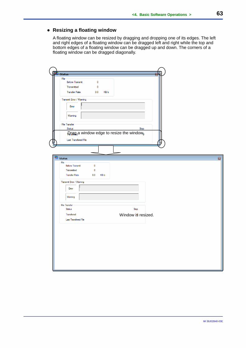
● Resizing a floating window A floating window can be resized by dragging and dropping one of its edges. The left and right edges of a floating window can be dragged left and right while the top and bottom edges of a floating window can be dragged up and down. The corners of a floating window can be dragged diagonally.
Window is resized.
Drag a window edge to resize the window.
<4. Basic Software Operations > 64
IM 39J02B40-03E
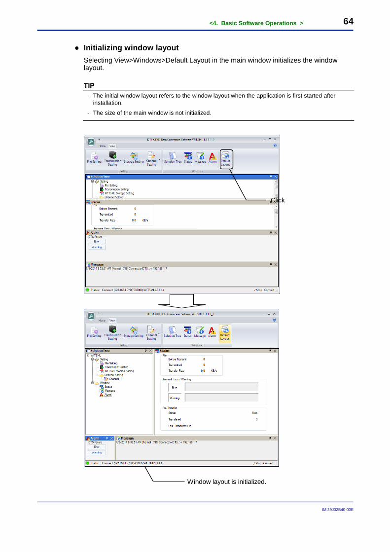
● Initializing window layout Selecting View>Windows>Default Layout in the main window initializes the window layout.
TIP - The initial window layout refers to the window layout when the application is first started after
installation.
- The size of the main window is not initialized.
Window layout is initialized.
Click
<4. Basic Software Operations > 65
IM 39J02B40-03E
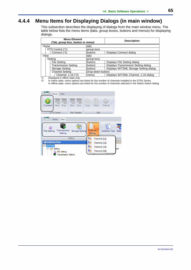
4.4.4 Menu Items for Displaying Dialogs (in main window) This subsection describes the displaying of dialogs from the main window menu. The table below lists the menu items (tabs, group boxes, buttons and menus) for displaying dialogs.
Menu Element (Tab, group box, button or menu) Description
Home (tab)
DTS Control (*1) (group box) Connect (*1) (button) Displays Connect dialog
View (tab)
Setting (group box)
File Setting (button) Displays File Setting dialog Transmission Setting (button) Displays Transmission Setting dialog Storage Setting (button) Displays WITSML Storage Setting dialog Channel Setting (Drop-down button) Channel_1-16 (*2) (menu) Displays WITSML Channel_1-16 dialog
*1: Displayed in offline state only. *2: In online state, menu options are listed for the number of channels installed in the DTSX Series.
In offline state, menu options are listed for the number of channels selected in the Select Switch dialog.
<4. Basic Software Operations > 66
IM 39J02B40-03E
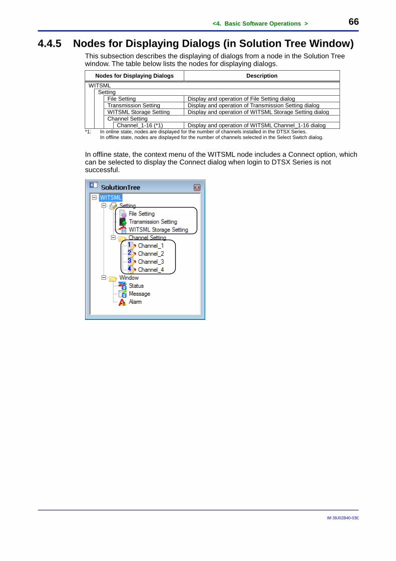
4.4.5 Nodes for Displaying Dialogs (in Solution Tree Window) This subsection describes the displaying of dialogs from a node in the Solution Tree window. The table below lists the nodes for displaying dialogs.
Nodes for Displaying Dialogs Description WITSML
Setting
File Setting Display and operation of File Setting dialog Transmission Setting Display and operation of Transmission Setting dialog WITSML Storage Setting Display and operation of WITSML Storage Setting dialog Channel Setting Channel_1-16 (*1) Display and operation of WITSML Channel_1-16 dialog
*1: In online state, nodes are displayed for the number of channels installed in the DTSX Series. In offline state, nodes are displayed for the number of channels selected in the Select Switch dialog.
In offline state, the context menu of the WITSML node includes a Connect option, which can be selected to display the Connect dialog when login to DTSX Series is not successful.
<4. Basic Software Operations > 67
IM 39J02B40-03E
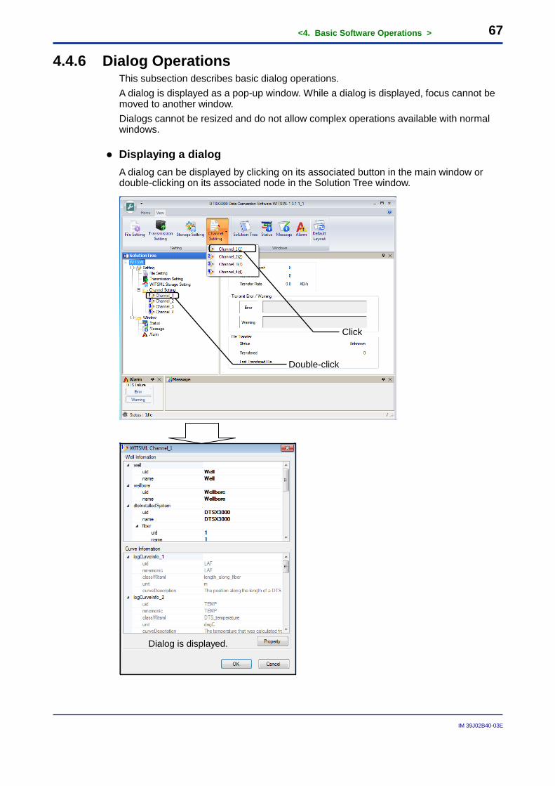
4.4.6 Dialog Operations This subsection describes basic dialog operations. A dialog is displayed as a pop-up window. While a dialog is displayed, focus cannot be moved to another window. Dialogs cannot be resized and do not allow complex operations available with normal windows.
● Displaying a dialog A dialog can be displayed by clicking on its associated button in the main window or double-clicking on its associated node in the Solution Tree window.
Dialog is displayed.
Click
Double-click
<4. Basic Software Operations > 68
IM 39J02B40-03E
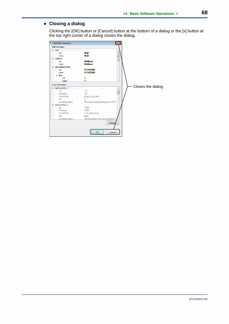
● Closing a dialog Clicking the [OK] button or [Cancel] button at the bottom of a dialog or the [x] button at the top right corner of a dialog closes the dialog.
Closes the dialog.

<4. Basic Software Operations > 69
IM 39J02B40-03E
4.5 Starting and Stopping Measurement You can start, as well as stop WITSML file conversion by the DTSX Series from the menu of the main window or a context menu in the Solution Tree window. Starting and stopping conversion is allowed only when the DTSX Series is connected in online state. If file transmission is specified on the Transmission Setting dialog, transmission also begins when conversion begins and stops when conversion stops. Moreover, conversion can be started only when it is not in progress and conversely can be stopped only when it is in progress.
Menu or Context Menu Item Online State Offline State
Start Ο(*1) X
Stop Ο(*2) X Ο Displayed X Not displayed *1: Executable when connected to DTSX Series and conversion is not in progress *2: Executable when connected to DTSX Series and conversion is in progress
TIP1 After conversion is started, the DTSX Series converts measurement result data to WITSML files after each measurement. Thus, WITSML files cannot be created unless measurement is started.
SEE ALSO For details on measurement by the DTSX3000, see the DTSX3000 Guide (IM39J06B40-01E).
TIP2 If the Transmit checkbox is selected on the Transmission Setting dialog, the following Server & Transmit File Settings dialog is displayed when you start conversion.
Click the [OK] button to begin conversion. Clicking the [Cancel] button aborts conversion.
<4. Basic Software Operations > 70
IM 39J02B40-03E
SEE ALSO For details, see Section 5.2, “File Transmission Settings.”
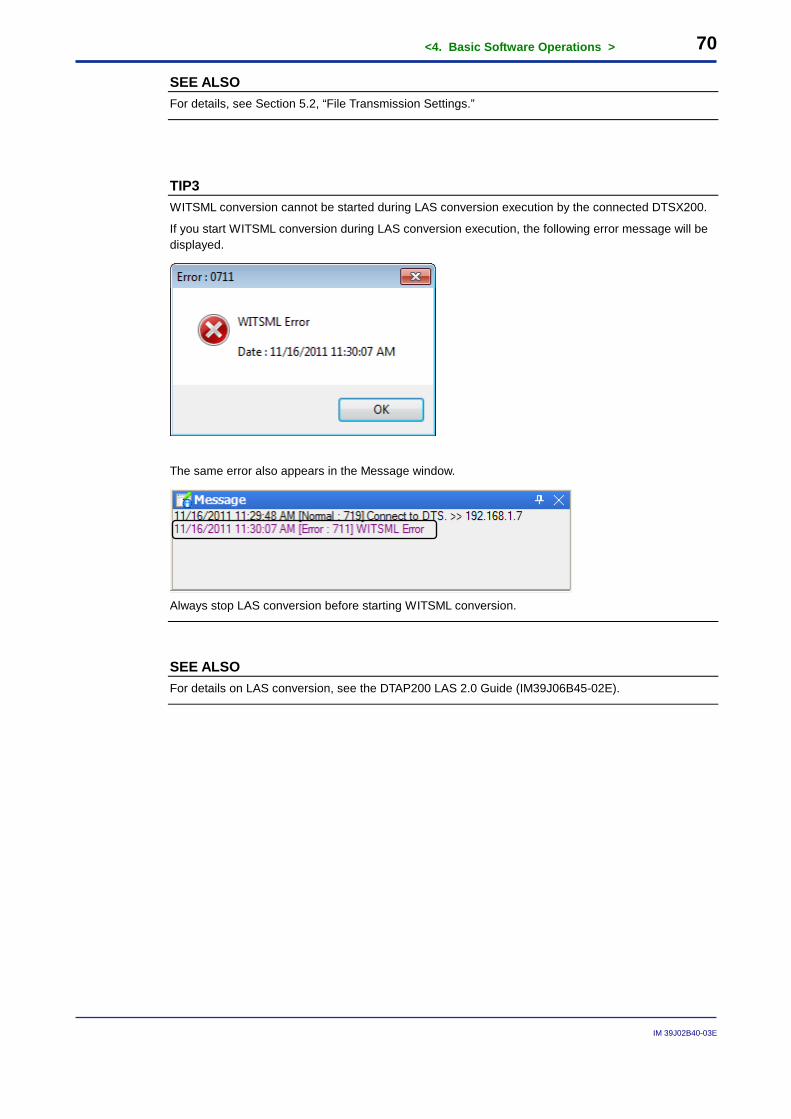
TIP3 WITSML conversion cannot be started during LAS conversion execution by the connected DTSX200.
If you start WITSML conversion during LAS conversion execution, the following error message will be displayed.
The same error also appears in the Message window.
Always stop LAS conversion before starting WITSML conversion.
SEE ALSO For details on LAS conversion, see the DTAP200 LAS 2.0 Guide (IM39J06B45-02E).
<4. Basic Software Operations > 71
IM 39J02B40-03E
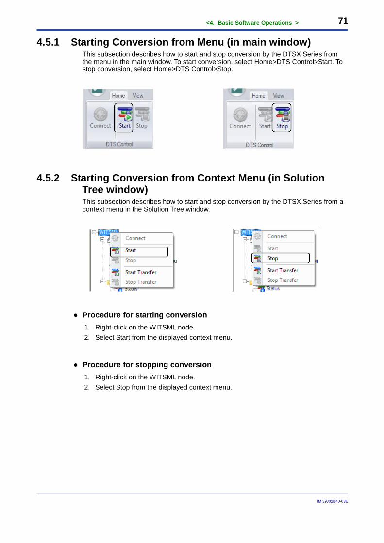
4.5.1 Starting Conversion from Menu (in main window) This subsection describes how to start and stop conversion by the DTSX Series from the menu in the main window. To start conversion, select Home>DTS Control>Start. To stop conversion, select Home>DTS Control>Stop.
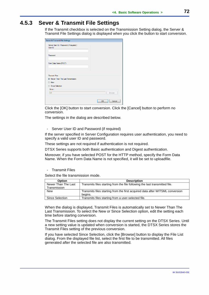
4.5.2 Starting Conversion from Context Menu (in Solution Tree window) This subsection describes how to start and stop conversion by the DTSX Series from a context menu in the Solution Tree window.
● Procedure for starting conversion 1. Right-click on the WITSML node. 2. Select Start from the displayed context menu.
● Procedure for stopping conversion 1. Right-click on the WITSML node. 2. Select Stop from the displayed context menu.
<4. Basic Software Operations > 72
IM 39J02B40-03E
4.5.3 Sever & Transmit File Settings If the Transmit checkbox is selected on the Transmission Setting dialog, the Server & Transmit File Settings dialog is displayed when you click the button to start conversion.
Click the [OK] button to start conversion. Click the [Cancel] button to perform no conversion. The settings in the dialog are described below.
- Server User ID and Password (if required) If the server specified in Server Configuration requires user authentication, you need to specify a valid user ID and password. These settings are not required if authentication is not required. DTSX Series supports both Basic authentication and Digest authentication. Moreover, if you have selected POST for the HTTP method, specify the Form Data Name. When the Form Data Name is not specified, it will be set to uploadfile. - Transmit Files
Select the file transmission mode. Option Description
Newer Than The Last Transmission
Transmits files starting from the file following the last transmitted file.
New Transmits files starting from the first acquired data after WITSML conversion begins.
Since Selection Transmits files starting from a user-selected file. When the dialog is displayed, Transmit Files is automatically set to Newer Than The Last Transmission. To select the New or Since Selection option, edit the setting each time before starting conversion. The Transmit Files setting does not display the current setting on the DTSX Series. Until a new setting value is updated when conversion is started, the DTSX Series stores the Transmit Files setting of the previous conversion. If you have selected Since Selection, click the [Browse] button to display the File List dialog. From the displayed file list, select the first file to be transmitted. All files generated after the selected file are also transmitted.
<4. Basic Software Operations > 73
IM 39J02B40-03E
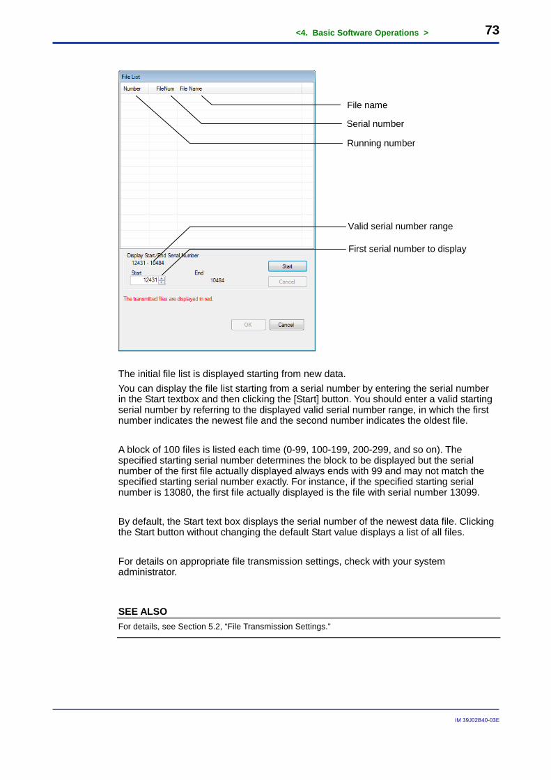
The initial file list is displayed starting from new data. You can display the file list starting from a serial number by entering the serial number in the Start textbox and then clicking the [Start] button. You should enter a valid starting serial number by referring to the displayed valid serial number range, in which the first number indicates the newest file and the second number indicates the oldest file. A block of 100 files is listed each time (0-99, 100-199, 200-299, and so on). The specified starting serial number determines the block to be displayed but the serial number of the first file actually displayed always ends with 99 and may not match the specified starting serial number exactly. For instance, if the specified starting serial number is 13080, the first file actually displayed is the file with serial number 13099. By default, the Start text box displays the serial number of the newest data file. Clicking the Start button without changing the default Start value displays a list of all files. For details on appropriate file transmission settings, check with your system administrator.
SEE ALSO For details, see Section 5.2, “File Transmission Settings.”
Valid serial number range
First serial number to display
Running number
Serial number
File name
<4. Basic Software Operations > 74
IM 39J02B40-03E
4.6 Starting and Stopping File Transfer You can start and stop transfer of WITSML files created by DTSX Series to the PC from the menu of the main window or a context menu in the Solution Tree window. Starting and stopping of file transfer is allowed only when the DTSX Series is connected in online state. File transfer can be started only when it is not in progress and conversely can be stopped only when it is in progress.
Menu or
Context Menu Item Online state Offline state
Start Transfer Ο(*1) X
Stop Transfer Ο(*2) X Ο Displayed X Not displayed *1: Executable when connected to DTSX Series and file transfer is not in progress *2: Executable when connected to DTSX Series and file transfer is in progress
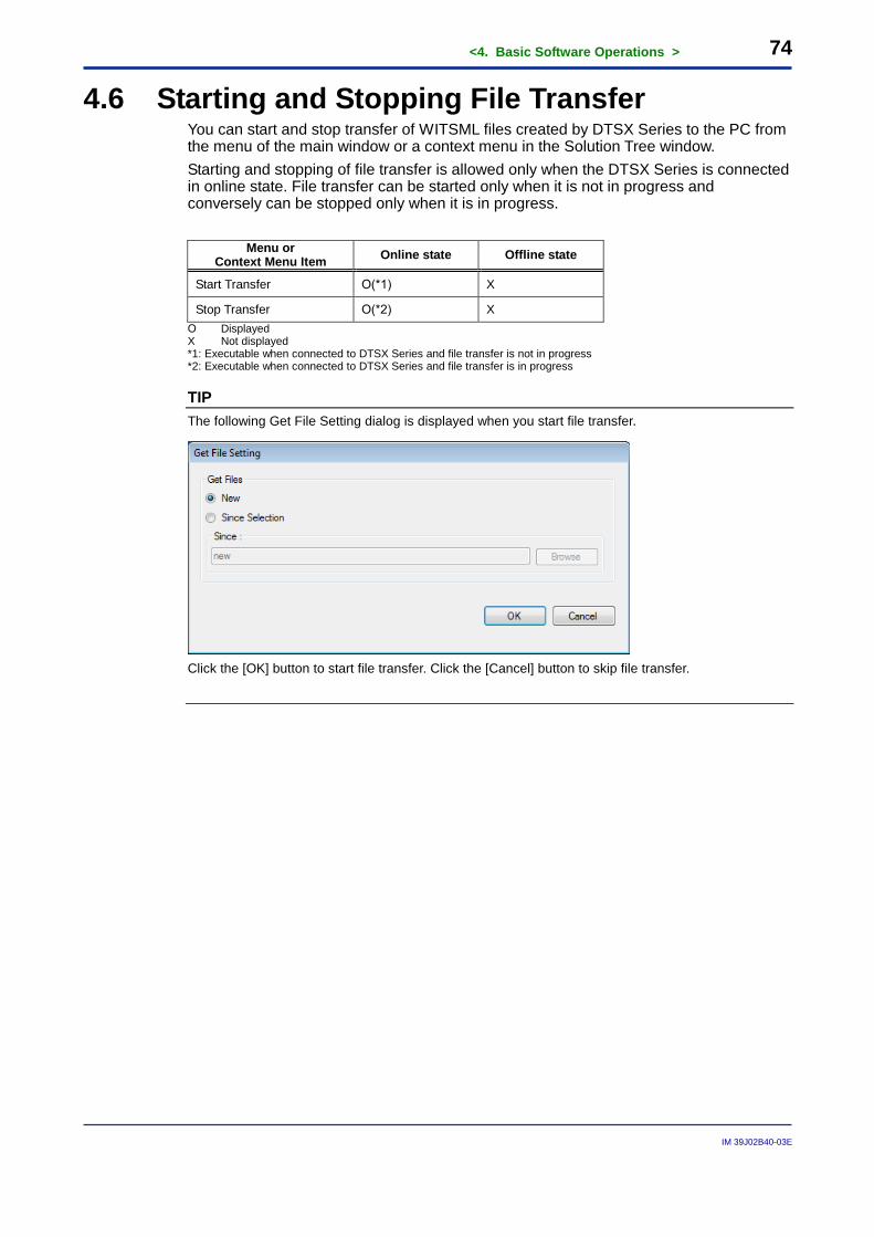
TIP The following Get File Setting dialog is displayed when you start file transfer.
Click the [OK] button to start file transfer. Click the [Cancel] button to skip file transfer.
<4. Basic Software Operations > 75
IM 39J02B40-03E
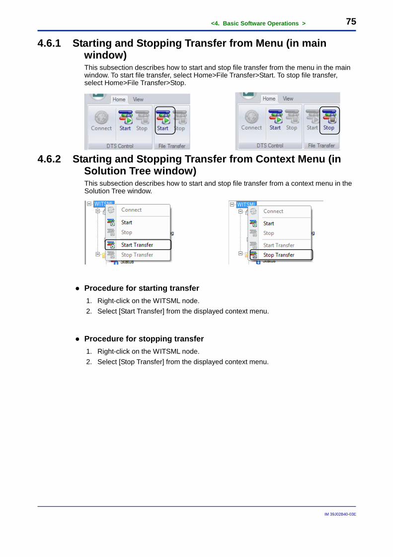
4.6.1 Starting and Stopping Transfer from Menu (in main window) This subsection describes how to start and stop file transfer from the menu in the main window. To start file transfer, select Home>File Transfer>Start. To stop file transfer, select Home>File Transfer>Stop.
4.6.2 Starting and Stopping Transfer from Context Menu (in
Solution Tree window) This subsection describes how to start and stop file transfer from a context menu in the Solution Tree window.
● Procedure for starting transfer 1. Right-click on the WITSML node. 2. Select [Start Transfer] from the displayed context menu.
● Procedure for stopping transfer 1. Right-click on the WITSML node. 2. Select [Stop Transfer] from the displayed context menu.
<4. Basic Software Operations > 76
IM 39J02B40-03E
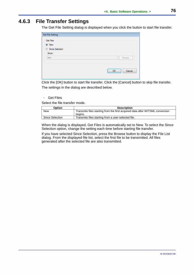
4.6.3 File Transfer Settings The Get File Setting dialog is displayed when you click the button to start file transfer.
Click the [OK] button to start file transfer. Click the [Cancel] button to skip file transfer. The settings in the dialog are described below. - Get Files
Select the file transfer mode. Option Description
New Transmits files starting from the first acquired data after WITSML conversion begins.
Since Selection Transmits files starting from a user-selected file. When the dialog is displayed, Get Files is automatically set to New. To select the Since Selection option, change the setting each time before starting file transfer. If you have selected Since Selection, press the Browse button to display the File List dialog. From the displayed file list, select the first file to be transmitted. All files generated after the selected file are also transmitted.
<4. Basic Software Operations > 77
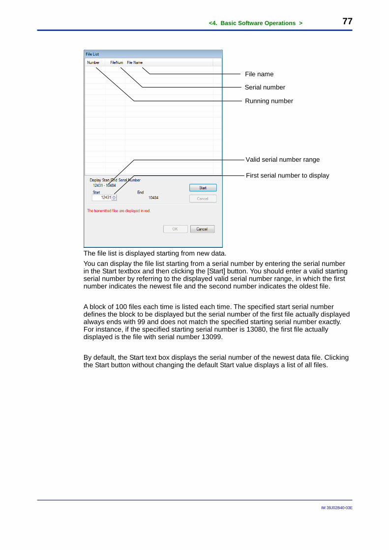
IM 39J02B40-03E
The file list is displayed starting from new data. You can display the file list starting from a serial number by entering the serial number in the Start textbox and then clicking the [Start] button. You should enter a valid starting serial number by referring to the displayed valid serial number range, in which the first number indicates the newest file and the second number indicates the oldest file. A block of 100 files each time is listed each time. The specified start serial number defines the block to be displayed but the serial number of the first file actually displayed always ends with 99 and does not match the specified starting serial number exactly. For instance, if the specified starting serial number is 13080, the first file actually displayed is the file with serial number 13099. By default, the Start text box displays the serial number of the newest data file. Clicking the Start button without changing the default Start value displays a list of all files.
Valid serial number range
First serial number to display
Running number
Serial number
File name
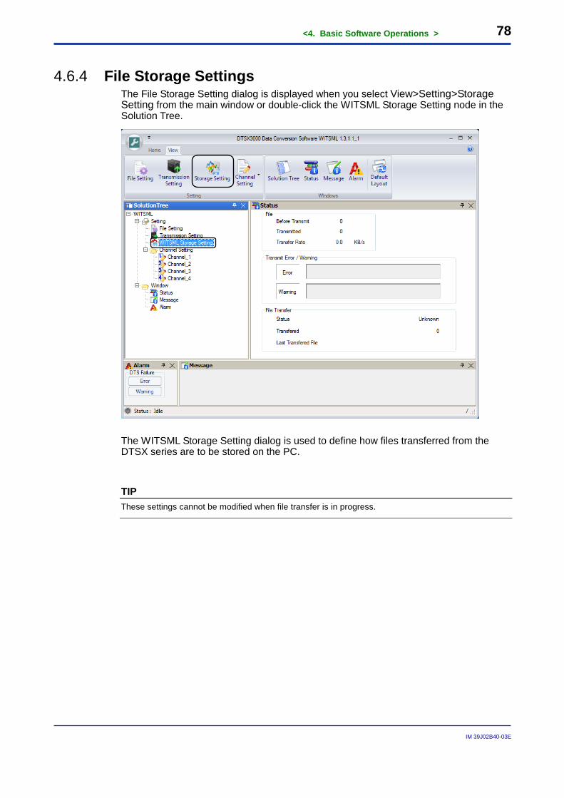
<4. Basic Software Operations > 78
IM 39J02B40-03E
4.6.4 File Storage Settings
The File Storage Setting dialog is displayed when you select View>Setting>Storage Setting from the main window or double-click the WITSML Storage Setting node in the Solution Tree.
The WITSML Storage Setting dialog is used to define how files transferred from the DTSX series are to be stored on the PC.
TIP These settings cannot be modified when file transfer is in progress.
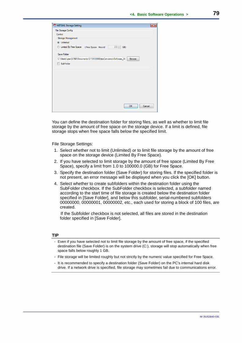
<4. Basic Software Operations > 79
IM 39J02B40-03E
You can define the destination folder for storing files, as well as whether to limit file storage by the amount of free space on the storage device. If a limit is defined, file storage stops when free space falls below the specified limit.
File Storage Settings: 1. Select whether not to limit (Unlimited) or to limit file storage by the amount of free
space on the storage device (Limited By Free Space). 2. If you have selected to limit storage by the amount of free space (Limited By Free
Space), specify a limit from 1.0 to 100000.0 (GB) for Free Space. 3. Specify the destination folder (Save Folder) for storing files. If the specified folder is
not present, an error message will be displayed when you click the [OK] button. 4. Select whether to create subfolders within the destination folder using the
SubFolder checkbox. If the SubFolder checkbox is selected, a subfolder named according to the start time of file storage is created below the destination folder specified in [Save Folder], and below this subfolder, serial-numbered subfolders 00000000, 00000001, 00000002, etc., each used for storing a block of 100 files, are created. If the Subfolder checkbox is not selected, all files are stored in the destination folder specified in [Save Folder].
TIP - Even if you have selected not to limit file storage by the amount of free space, if the specified
destination file (Save Folder) is on the system drive (C:), storage will stop automatically when free space falls below roughly 1 GB.
- File storage will be limited roughly but not strictly by the numeric value specified for Free Space.
- It is recommended to specify a destination folder (Save Folder) on the PC’s internal hard disk drive. If a network drive is specified, file storage may sometimes fail due to communications error.
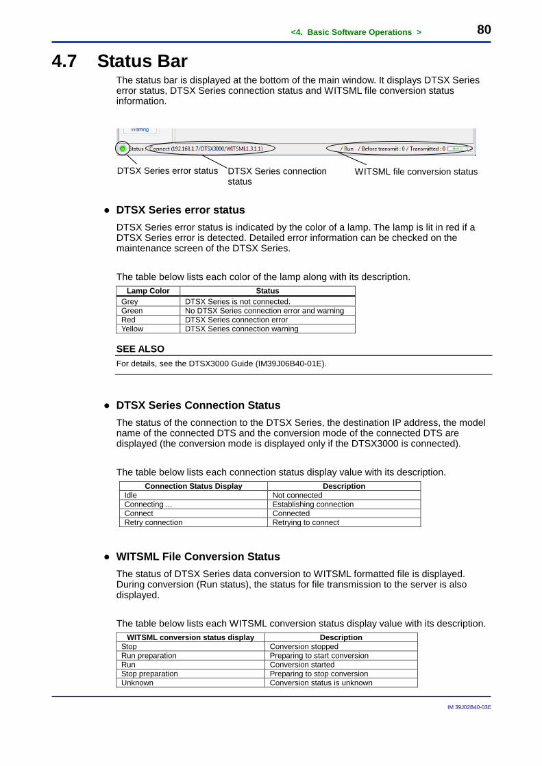
<4. Basic Software Operations > 80
IM 39J02B40-03E
4.7 Status Bar The status bar is displayed at the bottom of the main window. It displays DTSX Series error status, DTSX Series connection status and WITSML file conversion status information.
● DTSX Series error status DTSX Series error status is indicated by the color of a lamp. The lamp is lit in red if a DTSX Series error is detected. Detailed error information can be checked on the maintenance screen of the DTSX Series. The table below lists each color of the lamp along with its description.
Lamp Color Status Grey DTSX Series is not connected. Green No DTSX Series connection error and warning Red DTSX Series connection error Yellow DTSX Series connection warning
SEE ALSO For details, see the DTSX3000 Guide (IM39J06B40-01E).
● DTSX Series Connection Status The status of the connection to the DTSX Series, the destination IP address, the model name of the connected DTS and the conversion mode of the connected DTS are displayed (the conversion mode is displayed only if the DTSX3000 is connected). The table below lists each connection status display value with its description.
Connection Status Display Description Idle Not connected Connecting ... Establishing connection Connect Connected Retry connection Retrying to connect
● WITSML File Conversion Status The status of DTSX Series data conversion to WITSML formatted file is displayed. During conversion (Run status), the status for file transmission to the server is also displayed. The table below lists each WITSML conversion status display value with its description.
WITSML conversion status display Description Stop Conversion stopped Run preparation Preparing to start conversion Run Conversion started Stop preparation Preparing to stop conversion Unknown Conversion status is unknown
DTSX Series connection status
WITSML file conversion status DTSX Series error status

<4. Basic Software Operations > 81
IM 39J02B40-03E
During conversion (Run status), the following status information for WITSML file transmission to the server is displayed.
Status display Description Before transmit The number of files pending transmission to the server Transmitted The number of files already transmitted to the server
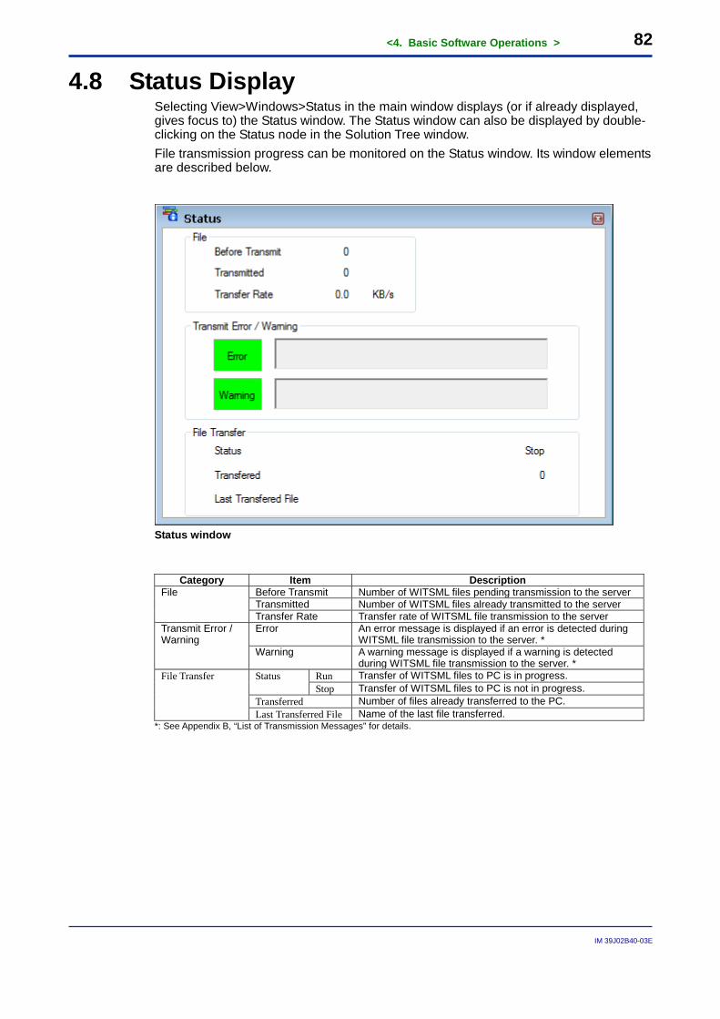
<4. Basic Software Operations > 82
IM 39J02B40-03E
4.8 Status Display Selecting View>Windows>Status in the main window displays (or if already displayed, gives focus to) the Status window. The Status window can also be displayed by double-clicking on the Status node in the Solution Tree window. File transmission progress can be monitored on the Status window. Its window elements are described below.
Status window
Category Item Description
File Before Transmit Number of WITSML files pending transmission to the server Transmitted Number of WITSML files already transmitted to the server Transfer Rate Transfer rate of WITSML file transmission to the server
Transmit Error / Warning
Error An error message is displayed if an error is detected during WITSML file transmission to the server. *
Warning A warning message is displayed if a warning is detected during WITSML file transmission to the server. *
File Transfer Status Run Transfer of WITSML files to PC is in progress. Stop Transfer of WITSML files to PC is not in progress.
Transferred Number of files already transferred to the PC. Last Transferred File Name of the last file transferred.
*: See Appendix B, “List of Transmission Messages” for details.
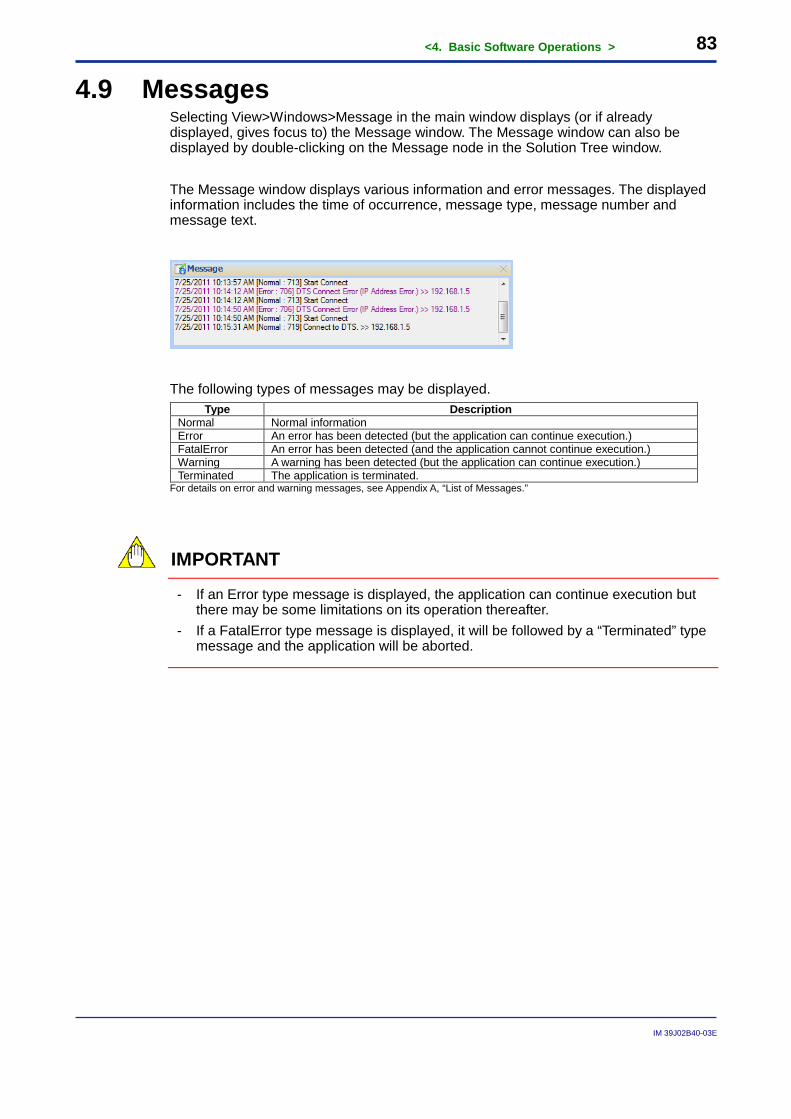
<4. Basic Software Operations > 83
IM 39J02B40-03E
4.9 Messages Selecting View>Windows>Message in the main window displays (or if already displayed, gives focus to) the Message window. The Message window can also be displayed by double-clicking on the Message node in the Solution Tree window. The Message window displays various information and error messages. The displayed information includes the time of occurrence, message type, message number and message text.
The following types of messages may be displayed. Type Description
Normal Normal information Error An error has been detected (but the application can continue execution.) FatalError An error has been detected (and the application cannot continue execution.) Warning A warning has been detected (but the application can continue execution.) Terminated The application is terminated.
For details on error and warning messages, see Appendix A, “List of Messages.”
IMPORTANT
- If an Error type message is displayed, the application can continue execution but there may be some limitations on its operation thereafter.
- If a FatalError type message is displayed, it will be followed by a “Terminated” type message and the application will be aborted.
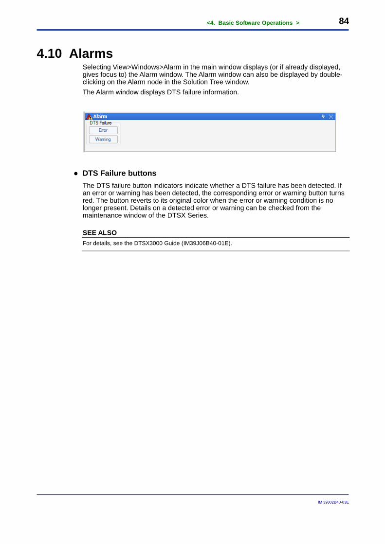
<4. Basic Software Operations > 84
IM 39J02B40-03E
4.10 Alarms Selecting View>Windows>Alarm in the main window displays (or if already displayed, gives focus to) the Alarm window. The Alarm window can also be displayed by double-clicking on the Alarm node in the Solution Tree window. The Alarm window displays DTS failure information.
● DTS Failure buttons The DTS failure button indicators indicate whether a DTS failure has been detected. If an error or warning has been detected, the corresponding error or warning button turns red. The button reverts to its original color when the error or warning condition is no longer present. Details on a detected error or warning can be checked from the maintenance window of the DTSX Series.
SEE ALSO For details, see the DTSX3000 Guide (IM39J06B40-01E).
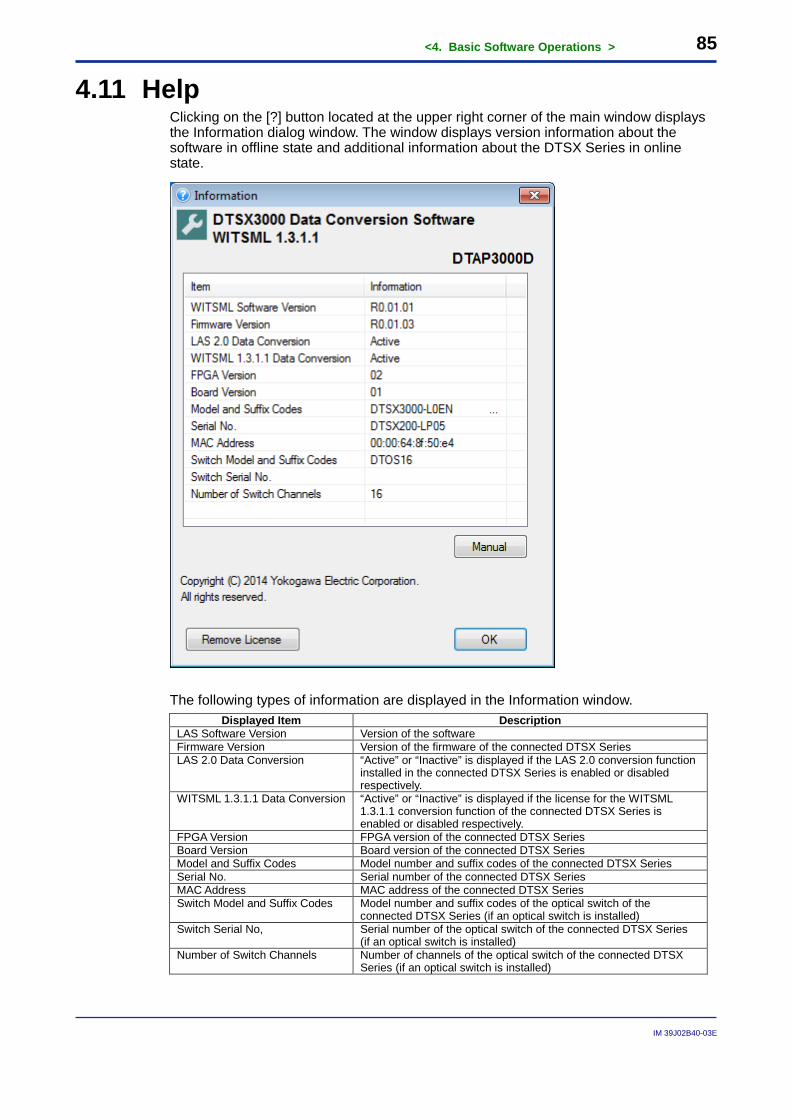
<4. Basic Software Operations > 85
IM 39J02B40-03E
4.11 Help Clicking on the [?] button located at the upper right corner of the main window displays the Information dialog window. The window displays version information about the software in offline state and additional information about the DTSX Series in online state.
The following types of information are displayed in the Information window.
Displayed Item Description LAS Software Version Version of the software Firmware Version Version of the firmware of the connected DTSX Series LAS 2.0 Data Conversion “Active” or “Inactive” is displayed if the LAS 2.0 conversion function
installed in the connected DTSX Series is enabled or disabled respectively.
WITSML 1.3.1.1 Data Conversion “Active” or “Inactive” is displayed if the license for the WITSML 1.3.1.1 conversion function of the connected DTSX Series is enabled or disabled respectively.
FPGA Version FPGA version of the connected DTSX Series Board Version Board version of the connected DTSX Series Model and Suffix Codes Model number and suffix codes of the connected DTSX Series Serial No. Serial number of the connected DTSX Series MAC Address MAC address of the connected DTSX Series Switch Model and Suffix Codes Model number and suffix codes of the optical switch of the
connected DTSX Series (if an optical switch is installed) Switch Serial No, Serial number of the optical switch of the connected DTSX Series
(if an optical switch is installed) Number of Switch Channels Number of channels of the optical switch of the connected DTSX
Series (if an optical switch is installed)

<4. Basic Software Operations > 86
IM 39J02B40-03E
Clicking the [Manual] button displays this manual in PDF format. Software capable of displaying PDF files must be pre-installed on the PC to view the manual. To remove the WITSML license from a DTSX3000, click the [Remove License] button. (This button is disabled when a DTSX200 is connected.)
SEE ALSO For details, see Section 3.5, “Removing License.”
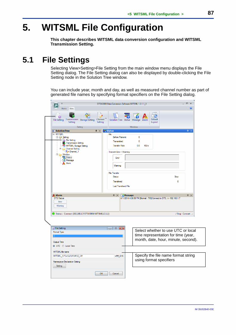
<5 WITSML File Configuration > 87
IM 39J02B40-03E
5. WITSML File Configuration This chapter describes WITSML data conversion configuration and WITSML Transmission Setting.
5.1 File Settings Selecting View>Setting>File Setting from the main window menu displays the File Setting dialog. The File Setting dialog can also be displayed by double-clicking the File Setting node in the Solution Tree window. You can include year, month and day, as well as measured channel number as part of generated file names by specifying format specifiers on the File Setting dialog.
Select whether to use UTC or local time representation for time (year, month, date, hour, minute, second).
Specify the file name format string using format specifiers
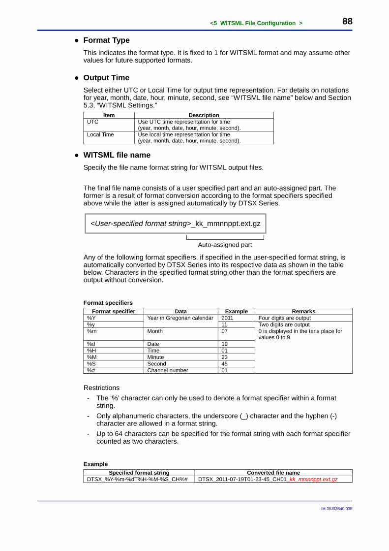
<5 WITSML File Configuration > 88
IM 39J02B40-03E
● Format Type This indicates the format type. It is fixed to 1 for WITSML format and may assume other values for future supported formats.
● Output Time Select either UTC or Local Time for output time representation. For details on notations for year, month, date, hour, minute, second, see “WITSML file name” below and Section 5.3, “WITSML Settings.”
Item Description UTC Use UTC time representation for time
(year, month, date, hour, minute, second). Local Time Use local time representation for time
(year, month, date, hour, minute, second).
● WITSML file name Specify the file name format string for WITSML output files. The final file name consists of a user specified part and an auto-assigned part. The former is a result of format conversion according to the format specifiers specified above while the latter is assigned automatically by DTSX Series.
<User-specified format string>_kk_mmnnppt.ext.gz
Auto-assigned part Any of the following format specifiers, if specified in the user-specified format string, is automatically converted by DTSX Series into its respective data as shown in the table below. Characters in the specified format string other than the format specifiers are output without conversion.
Format specifiers Format specifier Data Example Remarks
%Y Year in Gregorian calendar 2011 Four digits are output %y 11 Two digits are output %m Month 07 0 is displayed in the tens place for
values 0 to 9. %d Date 19 %H Time 01 %M Minute 23 %S Second 45 %# Channel number 01
Restrictions - The ‘%’ character can only be used to denote a format specifier within a format
string. - Only alphanumeric characters, the underscore (_) character and the hyphen (-)
character are allowed in a format string. - Up to 64 characters can be specified for the format string with each format specifier
counted as two characters.
Example Specified format string Converted file name
DTSX_%Y-%m-%dT%H-%M-%S_CH%# DTSX_2011-07-19T01-23-45_CH01_kk_mmnnppt.ext.gz
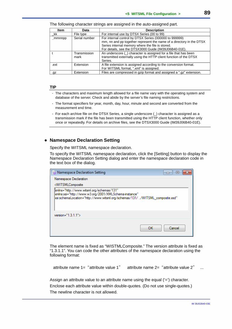
<5 WITSML File Configuration > 89
IM 39J02B40-03E
The following character strings are assigned in the auto-assigned part. Item Data Description
_kk File type For internal use by DTSX Series (00 to 99) _mmnnpp Serial number For internal control by DTSX Series (000000 to 999999) mm, nn and pp together represent the name of a directory in the DTSX
Series internal memory where the file is stored. For details, see the DTSX3000 Guide (IM39J06B40-01E).
t Transmission mark
An underscore (_) character is assigned for a file that has been transmitted externally using the HTTP client function of the DTSX Series.
.ext Extension A file extension is assigned according to the conversion format. For WITSML format, “.xml” is assigned.
.gz Extension Files are compressed in gzip format and assigned a “.gz” extension.
TIP - The characters and maximum length allowed for a file name vary with the operating system and
database of the server. Check and abide by the server’s file naming restrictions.
- The format specifiers for year, month, day, hour, minute and second are converted from the measurement end time.
- For each archive file on the DTSX Series, a single underscore (_) character is assigned as a transmission mark if the file has been transmitted using the HTTP client function, whether only once or repeatedly. For details on archive files, see the DTSX3000 Guide (IM39J06B40-01E).
● Namespace Declaration Setting Specify the WITSML namespace declaration. To specify the WITSML namespace declaration, click the [Setting] button to display the Namespace Declaration Setting dialog and enter the namespace declaration code in the text box of the dialog.
The element name is fixed as “WISTMLComposite.” The version attribute is fixed as “1.3.1.1”. You can code the other attributes of the namespace declaration using the following format: attribute name 1=“attribute value 1” attribute name 2=“attribute value 2” ... Assign an attribute value to an attribute name using the equal (‘=’) character. Enclose each attribute value within double-quotes. (Do not use single-quotes.) The newline character is not allowed.

<5 WITSML File Configuration > 90
IM 39J02B40-03E
TIP - If the specified namespace declaration is invalid by XML coding rules, the following default
namespace declaration will be output to a generated WITSML file:
<WITSMLComposite xmlns="http://www.witsml.org/schemas/131"
xmlns:xsi="http://www.w3.org/2001/XMLSchema-instance"
xsi:schemaLocation="http://www. witsml.org/schemas/131/ ../WITSML_composite.xsd" version="1.3.1.1">
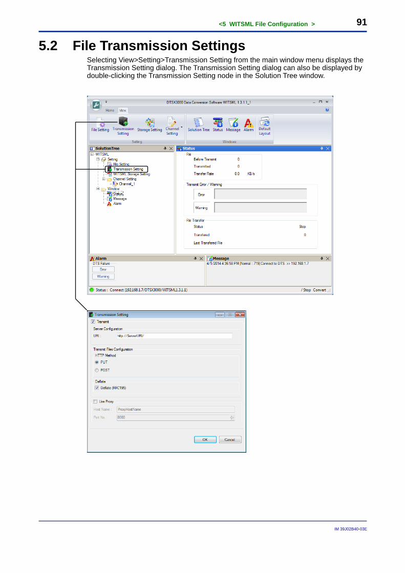
<5 WITSML File Configuration > 91
IM 39J02B40-03E
5.2 File Transmission Settings Selecting View>Setting>Transmission Setting from the main window menu displays the Transmission Setting dialog. The Transmission Setting dialog can also be displayed by double-clicking the Transmission Setting node in the Solution Tree window.
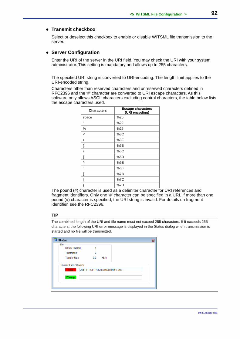
<5 WITSML File Configuration > 92
IM 39J02B40-03E
● Transmit checkbox Select or deselect this checkbox to enable or disable WITSML file transmission to the server.
● Server Configuration Enter the URI of the server in the URI field. You may check the URI with your system administrator. This setting is mandatory and allows up to 255 characters.
The specified URI string is converted to URI-encoding. The length limit applies to the URI-encoded string. Characters other than reserved characters and unreserved characters defined in RFC2396 and the ‘#’ character are converted to URI escape characters. As this software only allows ASCII characters excluding control characters, the table below lists the escape characters used.
Characters Escape characters (URI encoding)
space %20 " %22 % %25 < %3C > %3E [ %5B \ %5C ] %5D ^ %5E ` %60 { %7B | %7C } %7D
The pound (#) character is used as a delimiter character for URI references and fragment identifiers. Only one ‘#’ character can be specified in a URI. If more than one pound (#) character is specified, the URI string is invalid. For details on fragment identifier, see the RFC2396.
TIP The combined length of the URI and file name must not exceed 255 characters. If it exceeds 255 characters, the following URI error message is displayed in the Status dialog when transmission is started and no file will be transmitted.
<5 WITSML File Configuration > 93
IM 39J02B40-03E
SEE ALSO For details on generated file names, see Section 5.1, “File Settings.”
● HTTP Method Select whether to put or post files on the server.
Option Description PUT Transmits files to server using PUT POST Transmits files to server using POST
● Deflate Select or deselect this checkbox to enable or disable file deflation compliant to RFC195 (GZIP deflation).
● Use Proxy Select or deselect this checkbox to indicate whether a proxy server is used.
● Host Name If you have selected to use a proxy server, you must enter a host name or IP address of up to 255 characters for the proxy server.
● Port No. If you have selected to use a proxy server, you can optionally enter a port number of up to 65535 characters for the proxy server.
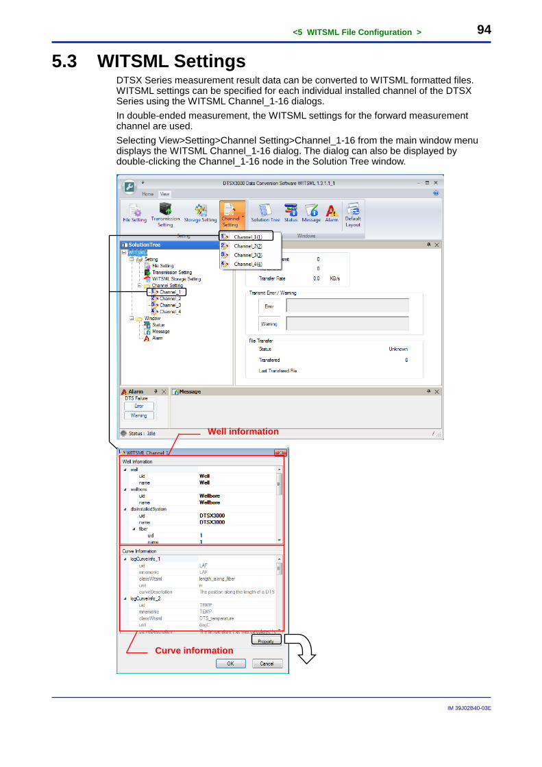
<5 WITSML File Configuration > 94
IM 39J02B40-03E
5.3 WITSML Settings DTSX Series measurement result data can be converted to WITSML formatted files. WITSML settings can be specified for each individual installed channel of the DTSX Series using the WITSML Channel_1-16 dialogs. In double-ended measurement, the WITSML settings for the forward measurement channel are used. Selecting View>Setting>Channel Setting>Channel_1-16 from the main window menu displays the WITSML Channel_1-16 dialog. The dialog can also be displayed by double-clicking the Channel_1-16 node in the Solution Tree window.
Well information
Curve information
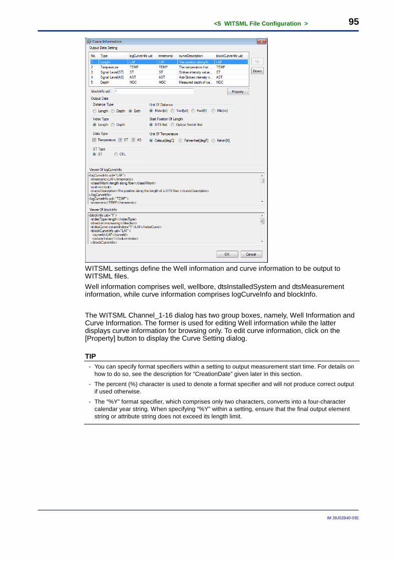
<5 WITSML File Configuration > 95
IM 39J02B40-03E
WITSML settings define the Well information and curve information to be output to WITSML files. Well information comprises well, wellbore, dtsInstalledSystem and dtsMeasurement information, while curve information comprises logCurveInfo and blockInfo. The WITSML Channel_1-16 dialog has two group boxes, namely, Well Information and Curve Information. The former is used for editing Well information while the latter displays curve information for browsing only. To edit curve information, click on the [Property] button to display the Curve Setting dialog.
TIP - You can specify format specifiers within a setting to output measurement start time. For details on
how to do so, see the description for “CreationDate” given later in this section.
- The percent (%) character is used to denote a format specifier and will not produce correct output if used otherwise.
- The “%Y” format specifier, which comprises only two characters, converts into a four-character calendar year string. When specifying “%Y” within a setting, ensure that the final output element string or attribute string does not exceed its length limit.
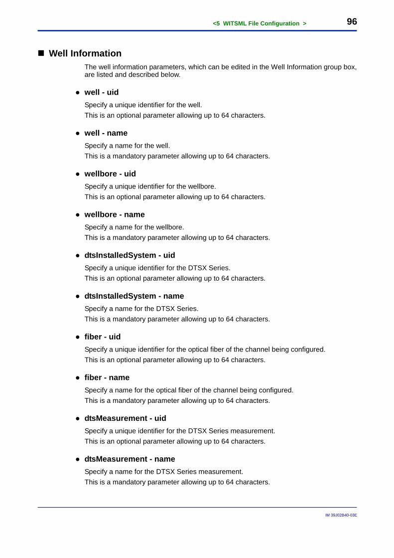
<5 WITSML File Configuration > 96
IM 39J02B40-03E
Well Information The well information parameters, which can be edited in the Well Information group box, are listed and described below.
● well - uid Specify a unique identifier for the well. This is an optional parameter allowing up to 64 characters.
● well - name Specify a name for the well. This is a mandatory parameter allowing up to 64 characters.
● wellbore - uid Specify a unique identifier for the wellbore. This is an optional parameter allowing up to 64 characters.
● wellbore - name Specify a name for the wellbore. This is a mandatory parameter allowing up to 64 characters.
● dtsInstalledSystem - uid Specify a unique identifier for the DTSX Series. This is an optional parameter allowing up to 64 characters.
● dtsInstalledSystem - name Specify a name for the DTSX Series. This is a mandatory parameter allowing up to 64 characters.
● fiber - uid Specify a unique identifier for the optical fiber of the channel being configured. This is an optional parameter allowing up to 64 characters.
● fiber - name Specify a name for the optical fiber of the channel being configured. This is a mandatory parameter allowing up to 64 characters.
● dtsMeasurement - uid Specify a unique identifier for the DTSX Series measurement. This is an optional parameter allowing up to 64 characters.
● dtsMeasurement - name Specify a name for the DTSX Series measurement. This is a mandatory parameter allowing up to 64 characters.
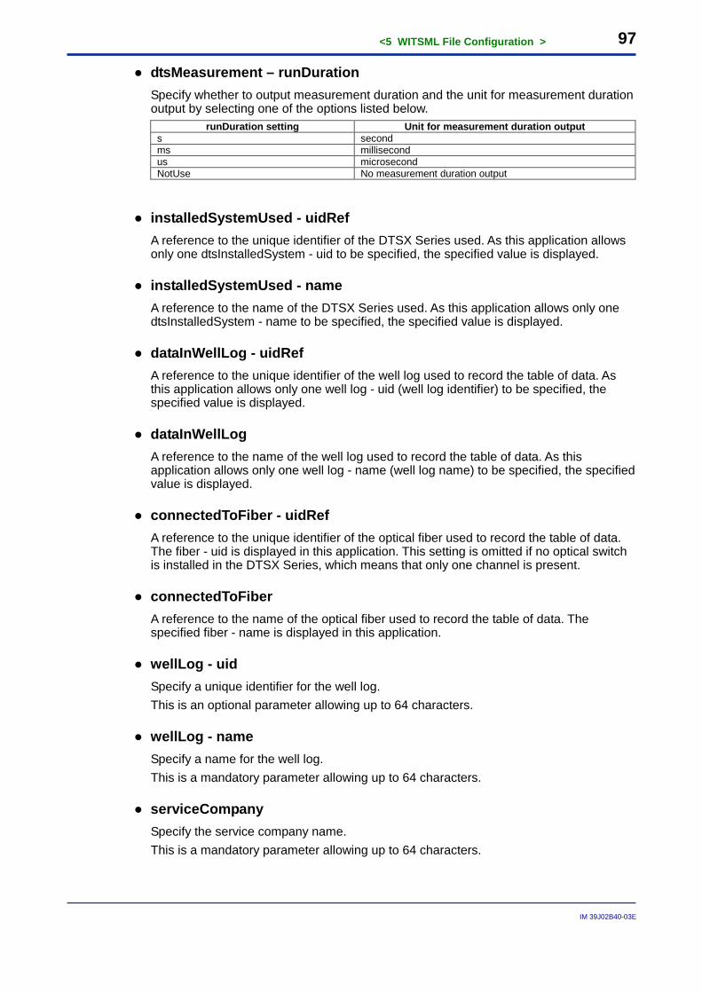
<5 WITSML File Configuration > 97
IM 39J02B40-03E
● dtsMeasurement – runDuration Specify whether to output measurement duration and the unit for measurement duration output by selecting one of the options listed below.
runDuration setting Unit for measurement duration output s second ms millisecond us microsecond NotUse No measurement duration output
● installedSystemUsed - uidRef A reference to the unique identifier of the DTSX Series used. As this application allows only one dtsInstalledSystem - uid to be specified, the specified value is displayed.
● installedSystemUsed - name A reference to the name of the DTSX Series used. As this application allows only one dtsInstalledSystem - name to be specified, the specified value is displayed.
● dataInWellLog - uidRef A reference to the unique identifier of the well log used to record the table of data. As this application allows only one well log - uid (well log identifier) to be specified, the specified value is displayed.
● dataInWellLog A reference to the name of the well log used to record the table of data. As this application allows only one well log - name (well log name) to be specified, the specified value is displayed.
● connectedToFiber - uidRef A reference to the unique identifier of the optical fiber used to record the table of data. The fiber - uid is displayed in this application. This setting is omitted if no optical switch is installed in the DTSX Series, which means that only one channel is present.
● connectedToFiber A reference to the name of the optical fiber used to record the table of data. The specified fiber - name is displayed in this application.
● wellLog - uid Specify a unique identifier for the well log. This is an optional parameter allowing up to 64 characters.
● wellLog - name Specify a name for the well log. This is a mandatory parameter allowing up to 64 characters.
● serviceCompany Specify the service company name. This is a mandatory parameter allowing up to 64 characters.
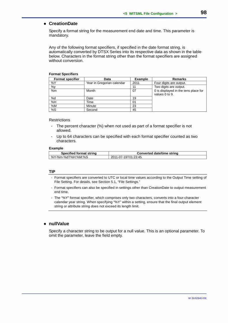
<5 WITSML File Configuration > 98
IM 39J02B40-03E
● CreationDate Specify a format string for the measurement end date and time. This parameter is mandatory. Any of the following format specifiers, if specified in the date format string, is automatically converted by DTSX Series into its respective data as shown in the table below. Characters in the format string other than the format specifiers are assigned without conversion.
Format Specifiers Format specifier Data Example Remarks
%Y Year in Gregorian calendar 2011 Four digits are output. %y 11 Two digits are output. %m Month 07 0 is displayed in the tens place for
values 0 to 9. %d Date 19 %H Time 01 %M Minute 23 %S Second 45
Restrictions - The percent character (%) when not used as part of a format specifier is not
allowed. - Up to 64 characters can be specified with each format specifier counted as two
characters.
Example Specified format string Converted date/time string
%Y-%m-%dT%H:%M:%S 2011-07-19T01:23:45
TIP - Format specifiers are converted to UTC or local time values according to the Output Time setting of
File Setting. For details, see Section 5.1, “File Settings.”
- Format specifiers can also be specified in settings other than CreationDate to output measurement end time.
- The “%Y” format specifier, which comprises only two characters, converts into a four-character calendar year string. When specifying “%Y” within a setting, ensure that the final output element string or attribute string does not exceed its length limit.
● nullValue Specify a character string to be output for a null value. This is an optional parameter. To omit the parameter, leave the field empty.
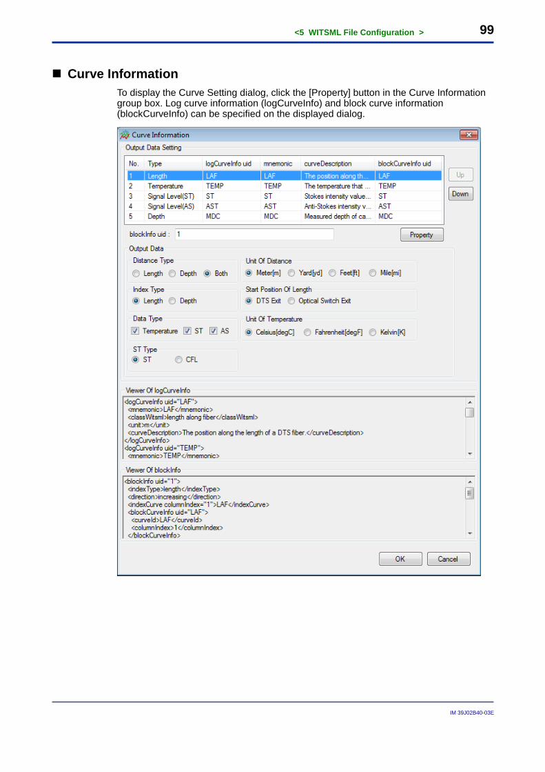
<5 WITSML File Configuration > 99
IM 39J02B40-03E
Curve Information To display the Curve Setting dialog, click the [Property] button in the Curve Information group box. Log curve information (logCurveInfo) and block curve information (blockCurveInfo) can be specified on the displayed dialog.
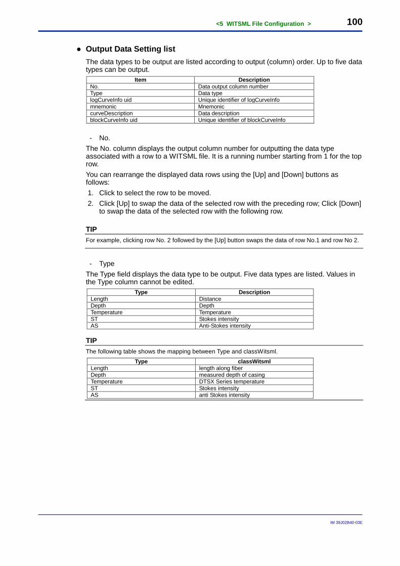
<5 WITSML File Configuration > 100
IM 39J02B40-03E
● Output Data Setting list The data types to be output are listed according to output (column) order. Up to five data types can be output.
Item Description No. Data output column number Type Data type logCurveInfo uid Unique identifier of logCurveInfo mnemonic Mnemonic curveDescription Data description blockCurveInfo uid Unique identifier of blockCurveInfo
- No.
The No. column displays the output column number for outputting the data type associated with a row to a WITSML file. It is a running number starting from 1 for the top row. You can rearrange the displayed data rows using the [Up] and [Down] buttons as follows: 1. Click to select the row to be moved. 2. Click [Up] to swap the data of the selected row with the preceding row; Click [Down]
to swap the data of the selected row with the following row.
TIP For example, clicking row No. 2 followed by the [Up] button swaps the data of row No.1 and row No 2.
- Type
The Type field displays the data type to be output. Five data types are listed. Values in the Type column cannot be edited.
Type Description Length Distance Depth Depth Temperature Temperature ST Stokes intensity AS Anti-Stokes intensity
TIP The following table shows the mapping between Type and classWitsml.
Type classWitsml Length length along fiber Depth measured depth of casing Temperature DTSX Series temperature ST Stokes intensity AS anti Stokes intensity
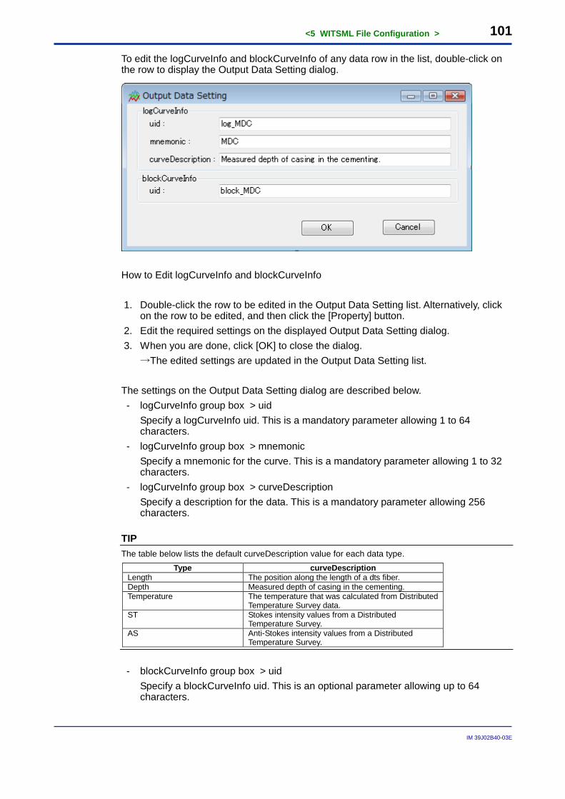
<5 WITSML File Configuration > 101
IM 39J02B40-03E
To edit the logCurveInfo and blockCurveInfo of any data row in the list, double-click on the row to display the Output Data Setting dialog.
How to Edit logCurveInfo and blockCurveInfo 1. Double-click the row to be edited in the Output Data Setting list. Alternatively, click
on the row to be edited, and then click the [Property] button. 2. Edit the required settings on the displayed Output Data Setting dialog. 3. When you are done, click [OK] to close the dialog. →The edited settings are updated in the Output Data Setting list. The settings on the Output Data Setting dialog are described below. - logCurveInfo group box > uid Specify a logCurveInfo uid. This is a mandatory parameter allowing 1 to 64
characters. - logCurveInfo group box > mnemonic Specify a mnemonic for the curve. This is a mandatory parameter allowing 1 to 32
characters. - logCurveInfo group box > curveDescription Specify a description for the data. This is a mandatory parameter allowing 256
characters.
TIP The table below lists the default curveDescription value for each data type.
Type curveDescription Length The position along the length of a dts fiber. Depth Measured depth of casing in the cementing. Temperature The temperature that was calculated from Distributed
Temperature Survey data. ST Stokes intensity values from a Distributed
Temperature Survey. AS Anti-Stokes intensity values from a Distributed
Temperature Survey.
- blockCurveInfo group box > uid Specify a blockCurveInfo uid. This is an optional parameter allowing up to 64
characters.
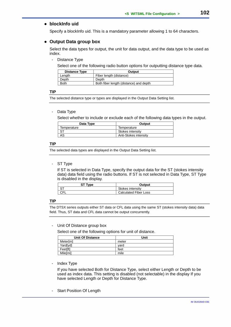
<5 WITSML File Configuration > 102
IM 39J02B40-03E
● blockInfo uid Specify a blockInfo uid. This is a mandatory parameter allowing 1 to 64 characters.
● Output Data group box Select the data types for output, the unit for data output, and the data type to be used as index. - Distance Type Select one of the following radio button options for outputting distance type data.
Distance Type Output Length Fiber length (distance) Depth Depth Both Both fiber length (distance) and depth
TIP The selected distance type or types are displayed in the Output Data Setting list.
- Data Type Select whether to include or exclude each of the following data types in the output.
Data Type Output Temperature Temperature ST Stokes intensity AS Anti-Stokes intensity
TIP The selected data types are displayed in the Output Data Setting list.
- ST Type If ST is selected in Data Type, specify the output data for the ST (stokes intensity
data) data field using the radio buttons. If ST is not selected in Data Type, ST Type is disabled in the display.
ST Type Output ST Stokes intensity CFL Calculated Fiber Loss
TIP The DTSX series outputs either ST data or CFL data using the same ST (stokes intensity data) data field. Thus, ST data and CFL data cannot be output concurrently.
- Unit Of Distance group box Select one of the following options for unit of distance.
Unit Of Distance Unit Meter[m] meter Yard[yd] yard Feet[ft] feet Mile[mi] mile
- Index Type If you have selected Both for Distance Type, select either Length or Depth to be
used as index data. This setting is disabled (not selectable) in the display If you have selected Length or Depth for Distance Type.
- Start Position Of Length
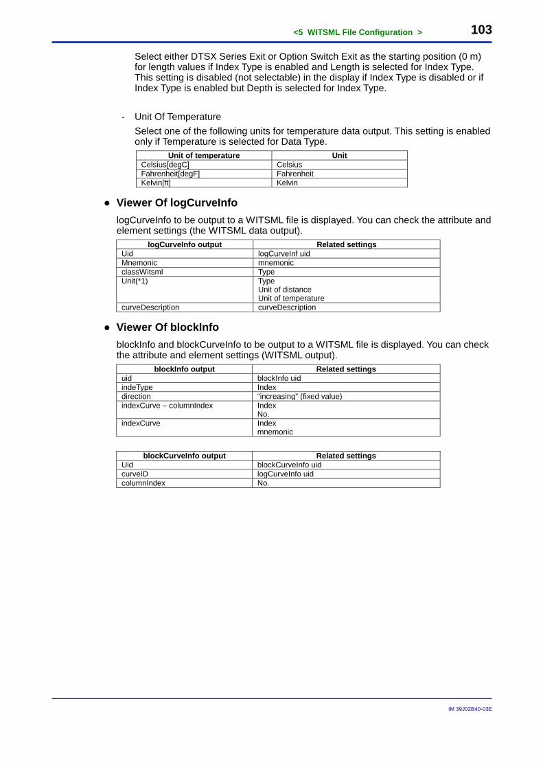
<5 WITSML File Configuration > 103
IM 39J02B40-03E
Select either DTSX Series Exit or Option Switch Exit as the starting position (0 m) for length values if Index Type is enabled and Length is selected for Index Type. This setting is disabled (not selectable) in the display if Index Type is disabled or if Index Type is enabled but Depth is selected for Index Type.
- Unit Of Temperature Select one of the following units for temperature data output. This setting is enabled
only if Temperature is selected for Data Type. Unit of temperature Unit
Celsius[degC] Celsius Fahrenheit[degF] Fahrenheit Kelvin[ft] Kelvin
● Viewer Of logCurveInfo logCurveInfo to be output to a WITSML file is displayed. You can check the attribute and element settings (the WITSML data output).
logCurveInfo output Related settings Uid logCurveInf uid Mnemonic mnemonic classWitsml Type Unit(*1) Type
Unit of distance Unit of temperature
curveDescription curveDescription
● Viewer Of blockInfo blockInfo and blockCurveInfo to be output to a WITSML file is displayed. You can check the attribute and element settings (WITSML output).
blockInfo output Related settings uid blockInfo uid indeType Index direction “increasing” (fixed value) indexCurve – columnIndex Index
No. indexCurve Index
mnemonic
blockCurveInfo output Related settings Uid blockCurveInfo uid curveID logCurveInfo uid columnIndex No.
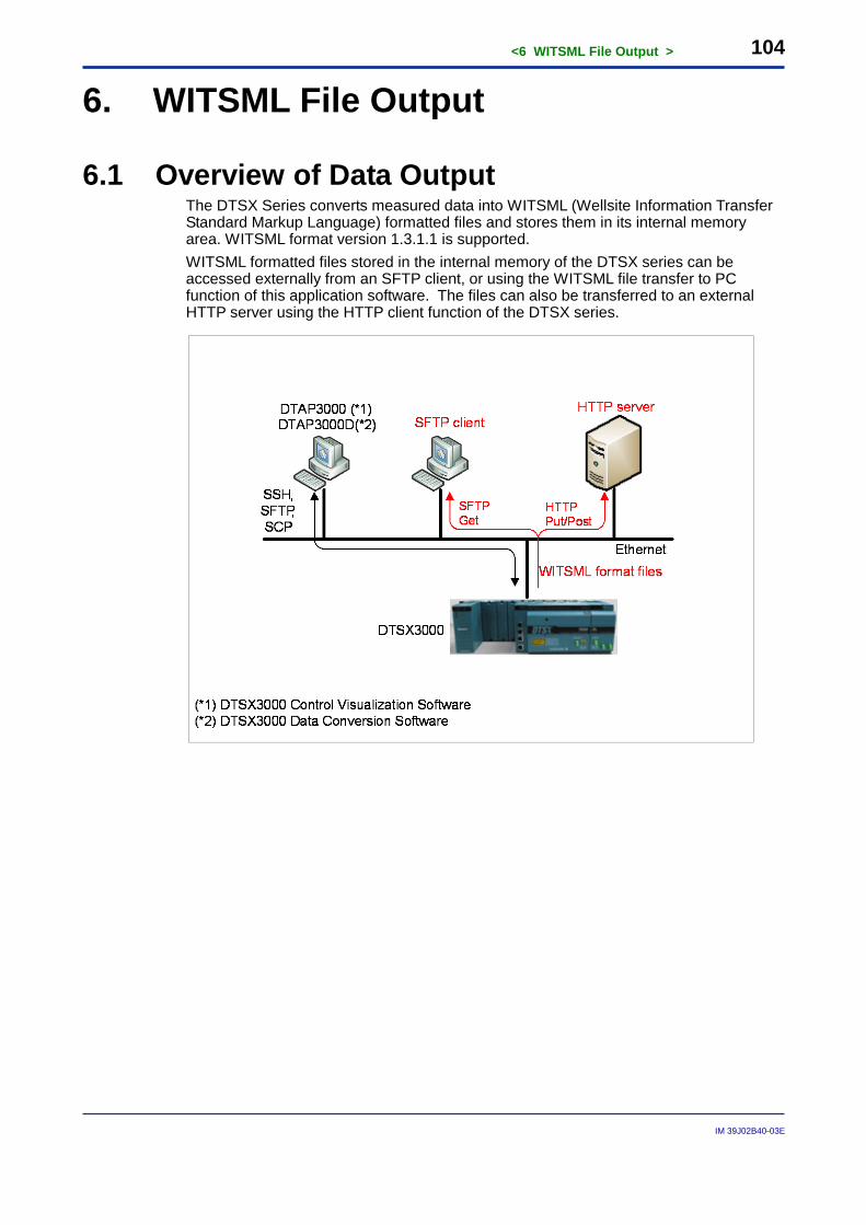
<6 WITSML File Output > 104
IM 39J02B40-03E
6. WITSML File Output
6.1 Overview of Data Output The DTSX Series converts measured data into WITSML (Wellsite Information Transfer Standard Markup Language) formatted files and stores them in its internal memory area. WITSML format version 1.3.1.1 is supported. WITSML formatted files stored in the internal memory of the DTSX series can be accessed externally from an SFTP client, or using the WITSML file transfer to PC function of this application software. The files can also be transferred to an external HTTP server using the HTTP client function of the DTSX series.
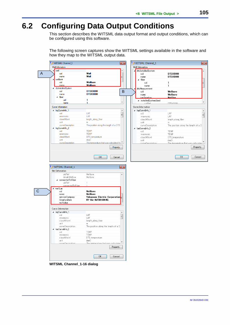
<6 WITSML File Output > 105
IM 39J02B40-03E
6.2 Configuring Data Output Conditions This section describes the WITSML data output format and output conditions, which can be configured using this software. The following screen captures show the WITSML settings available in the software and how they map to the WITSML output data.
WITSML Channel_1-16 dialog
A
B
C
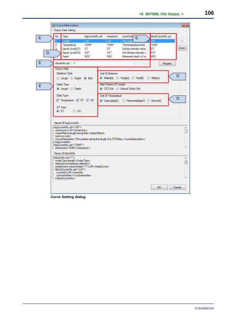
<6 WITSML File Output > 106
IM 39J02B40-03E
Curve Setting dialog
D
D
E
D
E
E
E
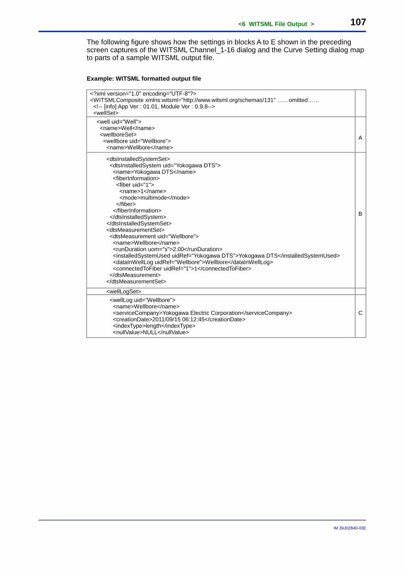
<6 WITSML File Output > 107
IM 39J02B40-03E
The following figure shows how the settings in blocks A to E shown in the preceding screen captures of the WITSML Channel_1-16 dialog and the Curve Setting dialog map to parts of a sample WITSML output file. Example: WITSML formatted output file
<?xml version="1.0" encoding="UTF-8"?> <WITSMLComposite xmlns:witsml="http://www.witsml.org/schemas/131" ……omitted…… <!-- [info] App Ver : 01.01, Module Ver : 0.9.8--> <wellSet>
<well uid="Well"> <name>Well</name> <wellboreSet> <wellbore uid="Wellbore"> <name>Wellbore</name>
A
<dtsInstalledSystemSet> <dtsInstalledSystem uid="Yokogawa DTS"> <name>Yokogawa DTS</name> <fiberInformation> <fiber uid="1"> <name>1</name> <mode>multimode</mode> </fiber> </fiberInformation> </dtsInstalledSystem> </dtsInstalledSystemSet> <dtsMeasurementSet> <dtsMeasurement uid="Wellbore"> <name>Wellbore</name> <runDuration uom="s">2.00</runDuration> <installedSystemUsed uidRef="Yokogawa DTS">Yokogawa DTS</installedSystemUsed> <dataInWellLog uidRef="Wellbore">Wellbore</dataInWellLog> <connectedToFiber uidRef="1">1</connectedToFiber> </dtsMeasurement> </dtsMeasurementSet>
B
<wellLogSet> <wellLog uid="Wellbore"> <name>Wellbore</name> <serviceCompany>Yokogawa Electric Corporation</serviceCompany> <creationDate>2011/09/15 06:12:45</creationDate> <indexType>length</indexType> <nullValue>NULL</nullValue>
C
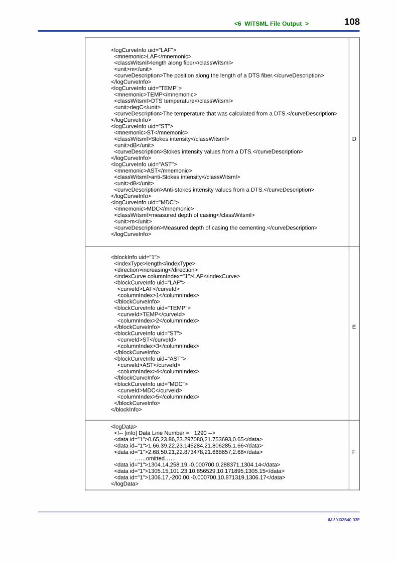
<6 WITSML File Output > 108
IM 39J02B40-03E
<logCurveInfo uid="LAF"> <mnemonic>LAF</mnemonic> <classWitsml>length along fiber</classWitsml> <unit>m</unit> <curveDescription>The position along the length of a DTS fiber.</curveDescription> </logCurveInfo> <logCurveInfo uid="TEMP"> <mnemonic>TEMP</mnemonic> <classWitsml>DTS temperature</classWitsml> <unit>degC</unit> <curveDescription>The temperature that was calculated from a DTS.</curveDescription> </logCurveInfo> <logCurveInfo uid="ST"> <mnemonic>ST</mnemonic> <classWitsml>Stokes intensity</classWitsml> <unit>dB</unit> <curveDescription>Stokes intensity values from a DTS.</curveDescription> </logCurveInfo> <logCurveInfo uid="AST"> <mnemonic>AST</mnemonic> <classWitsml>anti-Stokes intensity</classWitsml> <unit>dB</unit> <curveDescription>Anti-stokes intensity values from a DTS.</curveDescription> </logCurveInfo> <logCurveInfo uid="MDC"> <mnemonic>MDC</mnemonic> <classWitsml>measured depth of casing</classWitsml> <unit>m</unit> <curveDescription>Measured depth of casing the cementing.</curveDescription> </logCurveInfo>
D
<blockInfo uid="1"> <indexType>length</indexType> <direction>increasing</direction> <indexCurve columnIndex="1">LAF</indexCurve> <blockCurveInfo uid="LAF"> <curveId>LAF</curveId> <columnIndex>1</columnIndex> </blockCurveInfo> <blockCurveInfo uid="TEMP"> <curveId>TEMP</curveId> <columnIndex>2</columnIndex> </blockCurveInfo> <blockCurveInfo uid="ST"> <curveId>ST</curveId> <columnIndex>3</columnIndex> </blockCurveInfo> <blockCurveInfo uid="AST"> <curveId>AST</curveId> <columnIndex>4</columnIndex> </blockCurveInfo> <blockCurveInfo uid="MDC"> <curveId>MDC</curveId> <columnIndex>5</columnIndex> </blockCurveInfo> </blockInfo>
E
<logData> <!-- [info] Data Line Number = 1290 --> <data id="1">0.65,23.86,23.297080,21.753693,0.65</data> <data id="1">1.66,39.22,23.145284,21.806285,1.66</data> <data id="1">2.68,50.21,22.873478,21.668657,2.68</data> ……omitted…… <data id="1">1304.14,258.19,-0.000700,0.288371,1304.14</data> <data id="1">1305.15,101.23,10.856529,10.171895,1305.15</data> <data id="1">1306.17,-200.00,-0.000700,10.871319,1306.17</data> </logData>
F
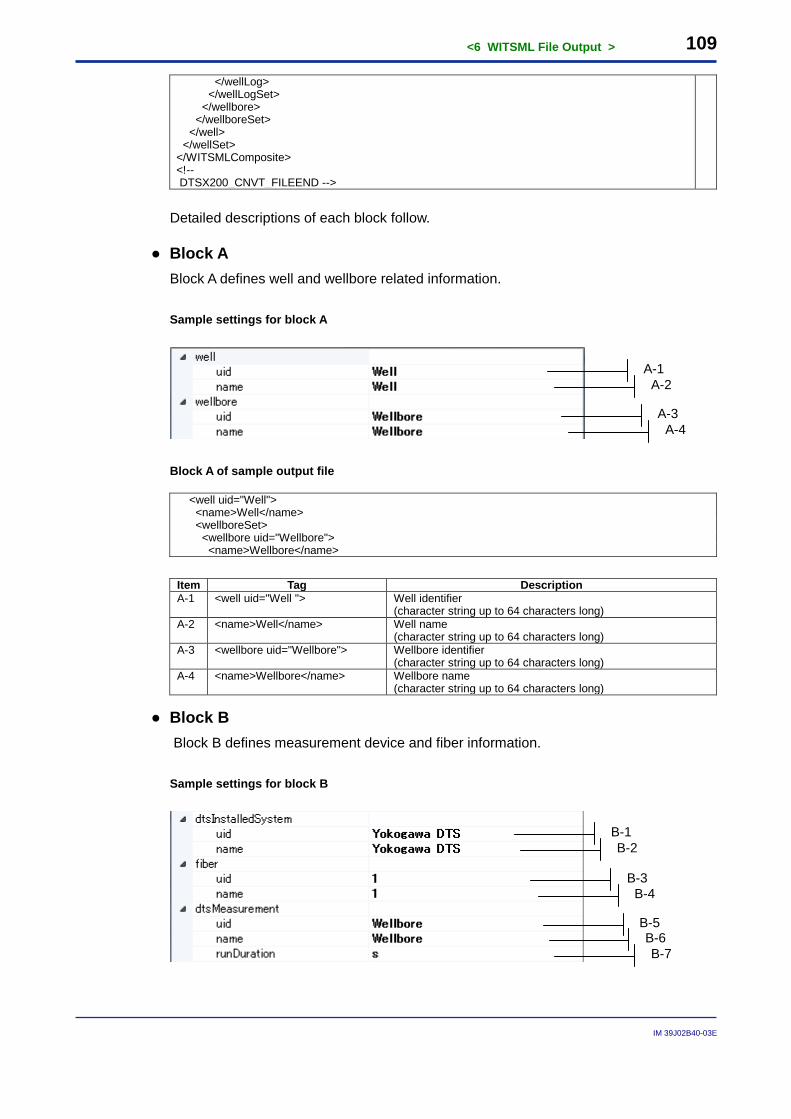
<6 WITSML File Output > 109
IM 39J02B40-03E
</wellLog> </wellLogSet> </wellbore> </wellboreSet> </well> </wellSet> </WITSMLComposite> <!-- DTSX200_CNVT_FILEEND -->
Detailed descriptions of each block follow.
● Block A Block A defines well and wellbore related information. Sample settings for block A
Block A of sample output file
<well uid="Well"> <name>Well</name> <wellboreSet> <wellbore uid="Wellbore"> <name>Wellbore</name>
Item Tag Description A-1 <well uid="Well "> Well identifier
(character string up to 64 characters long) A-2 <name>Well</name> Well name
(character string up to 64 characters long) A-3 <wellbore uid="Wellbore"> Wellbore identifier
(character string up to 64 characters long) A-4 <name>Wellbore</name> Wellbore name
(character string up to 64 characters long)
● Block B Block B defines measurement device and fiber information.
Sample settings for block B
A-1 A-2
A-3 A-4
B-1 B-2
B-3 B-4
B-5 B-6 B-7
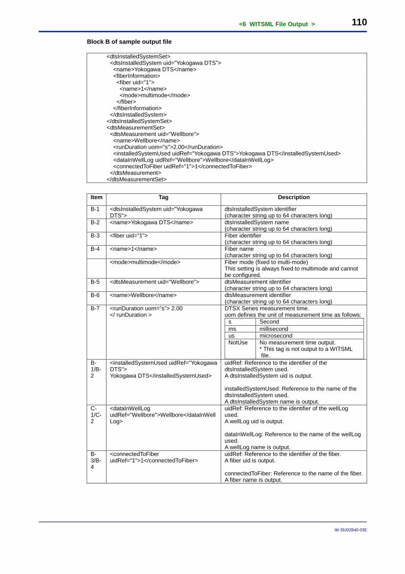
<6 WITSML File Output > 110
IM 39J02B40-03E
Block B of sample output file
<dtsInstalledSystemSet> <dtsInstalledSystem uid="Yokogawa DTS"> <name>Yokogawa DTS</name> <fiberInformation> <fiber uid="1"> <name>1</name> <mode>multimode</mode> </fiber> </fiberInformation> </dtsInstalledSystem> </dtsInstalledSystemSet> <dtsMeasurementSet> <dtsMeasurement uid="Wellbore"> <name>Wellbore</name> <runDuration uom="s">2.00</runDuration> <installedSystemUsed uidRef="Yokogawa DTS">Yokogawa DTS</installedSystemUsed> <dataInWellLog uidRef="Wellbore">Wellbore</dataInWellLog> <connectedToFiber uidRef="1">1</connectedToFiber> </dtsMeasurement> </dtsMeasurementSet>
Item Tag Description
B-1 <dtsInstalledSystem uid="Yokogawa DTS">
dtsInstalledSystem identifier (character string up to 64 characters long)
B-2 <name>Yokogawa DTS</name> dtsInstalledSystem name (character string up to 64 characters long)
B-3 <fiber uid="1"> Fiber identifier (character string up to 64 characters long)
B-4 <name>1</name> Fiber name (character string up to 64 characters long)
<mode>multimode</mode> Fiber mode (fixed to multi-mode) This setting is always fixed to multimode and cannot be configured.
B-5 <dtsMeasurement uid="Wellbore"> dtsMeasurement identifier (character string up to 64 characters long)
B-6 <name>Wellbore</name> dtsMeasurement identifier (character string up to 64 characters long)
B-7 <runDuration uom=”s”> 2.00 </ runDuration >
DTSX Series measurement time. uom defines the unit of measurement time as follows:
s Second ms millisecond us microsecond NotUse No measurement time output.
* This tag is not output to a WITSML file.
B-1/B-2
<installedSystemUsed uidRef="Yokogawa DTS"> Yokogawa DTS</installedSystemUsed>
uidRef: Reference to the identifier of the dtsInstalledSystem used. A dtsInstalledSystem uid is output. installedSystemUsed: Reference to the name of the dtsInstalledSystem used. A dtsInstalledSystem name is output.
C-1/C-2
<dataInWellLog uidRef="Wellbore">Wellbore</dataInWellLog>
uidRef: Reference to the identifier of the wellLog used. A wellLog uid is output. dataInWellLog: Reference to the name of the wellLog used. A wellLog name is output.
B-3/B-4
<connectedToFiber uidRef="1">1</connectedToFiber>
uidRef: Reference to the identifier of the fiber. A fiber uid is output. connectedToFiber: Reference to the name of the fiber. A fiber name is output.
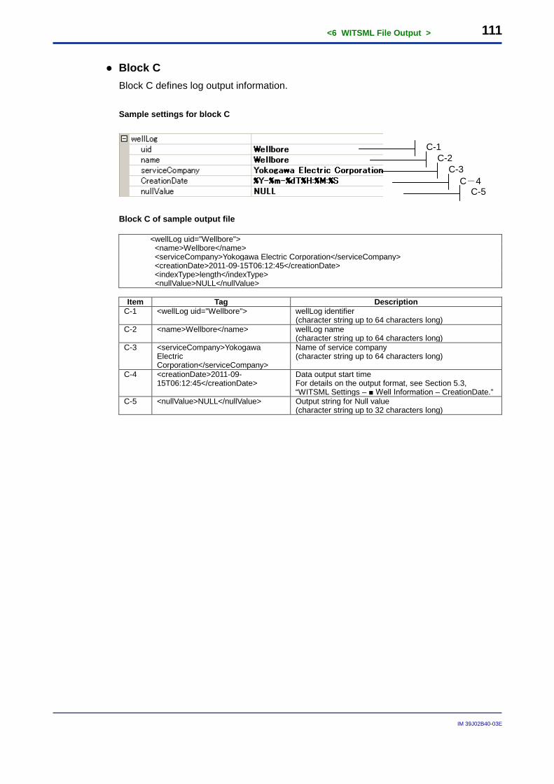
<6 WITSML File Output > 111
IM 39J02B40-03E
● Block C Block C defines log output information. Sample settings for block C
Block C of sample output file
<wellLog uid="Wellbore"> <name>Wellbore</name> <serviceCompany>Yokogawa Electric Corporation</serviceCompany> <creationDate>2011-09-15T06:12:45</creationDate> <indexType>length</indexType> <nullValue>NULL</nullValue>
Item Tag Description
C-1 <wellLog uid="Wellbore"> wellLog identifier (character string up to 64 characters long)
C-2 <name>Wellbore</name> wellLog name (character string up to 64 characters long)
C-3 <serviceCompany>Yokogawa Electric Corporation</serviceCompany>
Name of service company (character string up to 64 characters long)
C-4 <creationDate>2011-09-15T06:12:45</creationDate>
Data output start time For details on the output format, see Section 5.3, “WITSML Settings – ■ Well Information – CreationDate.”
C-5 <nullValue>NULL</nullValue> Output string for Null value (character string up to 32 characters long)
C-1 C-2
C-3 C-4
C-5
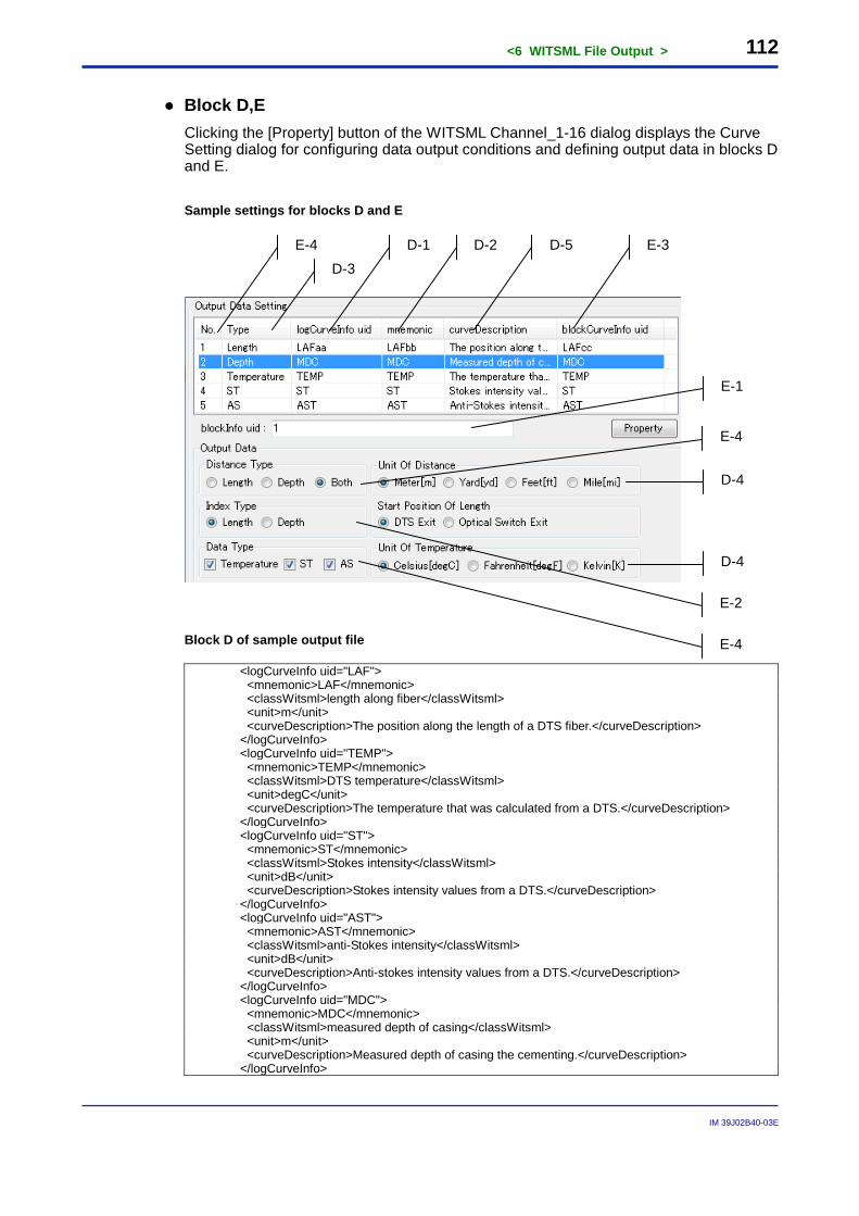
<6 WITSML File Output > 112
IM 39J02B40-03E
● Block D,E Clicking the [Property] button of the WITSML Channel_1-16 dialog displays the Curve Setting dialog for configuring data output conditions and defining output data in blocks D and E. Sample settings for blocks D and E
Block D of sample output file
<logCurveInfo uid="LAF"> <mnemonic>LAF</mnemonic> <classWitsml>length along fiber</classWitsml> <unit>m</unit> <curveDescription>The position along the length of a DTS fiber.</curveDescription> </logCurveInfo> <logCurveInfo uid="TEMP"> <mnemonic>TEMP</mnemonic> <classWitsml>DTS temperature</classWitsml> <unit>degC</unit> <curveDescription>The temperature that was calculated from a DTS.</curveDescription> </logCurveInfo> <logCurveInfo uid="ST"> <mnemonic>ST</mnemonic> <classWitsml>Stokes intensity</classWitsml> <unit>dB</unit> <curveDescription>Stokes intensity values from a DTS.</curveDescription> </logCurveInfo> <logCurveInfo uid="AST"> <mnemonic>AST</mnemonic> <classWitsml>anti-Stokes intensity</classWitsml> <unit>dB</unit> <curveDescription>Anti-stokes intensity values from a DTS.</curveDescription> </logCurveInfo> <logCurveInfo uid="MDC"> <mnemonic>MDC</mnemonic> <classWitsml>measured depth of casing</classWitsml> <unit>m</unit> <curveDescription>Measured depth of casing the cementing.</curveDescription> </logCurveInfo>
E-4 D-3
D-1 D-2 D-5 E-3
D-4
D-4
E-1
E-4
E-4
E-2
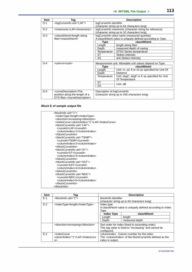
<6 WITSML File Output > 113
IM 39J02B40-03E
Item Tag Description D-1 <logCurveInfo uid="LAF"> logCurveInfo identifier
(character string up to 64 characters long) D-2 <mnemonic>LAF</mnemonic> logCurveInfo mnemonic (character string for reference)
(character string up to 32 characters long) D-3 <classWitsml>length along
fiber</classWitsml> logCurveInfo class name (measured quantity) A classWitsml value is uniquely defined according to Type.
Type classWitsml Length length along fiber Depth measured depth of casing Temperature DTSX Series temperature ST Stokes intensity AS anti Stokes intensity
D-4 <unit>m</unit> Measurement unit. Allowable unit values depend on Type. Type classWitsml
Length Unit: m, yd, ft or mi as specified for Unit Of Distance Depth
Temperature Unit: degC, degF or K as specified for Unit Of Temperature
ST Unit: dB AS
D-5 <curveDescription>The position along the length of a DTS fiber.</curveDescription>
Description of logCurveInfo (character string up to 256 characters long)
Block E of sample output file
<blockInfo uid="1"> <indexType>length</indexType> <direction>increasing</direction> <indexCurve columnIndex="1">LAF</indexCurve> <blockCurveInfo uid="LAF"> <curveId>LAF</curveId> <columnIndex>1</columnIndex> </blockCurveInfo> <blockCurveInfo uid="TEMP"> <curveId>TEMP</curveId> <columnIndex>2</columnIndex> </blockCurveInfo> <blockCurveInfo uid="ST"> <curveId>ST</curveId> <columnIndex>3</columnIndex> </blockCurveInfo> <blockCurveInfo uid="AST"> <curveId>AST</curveId> <columnIndex>4</columnIndex> </blockCurveInfo> <blockCurveInfo uid="MDC"> <curveId>MDC</curveId> <columnIndex>5</columnIndex> </blockCurveInfo> </blockInfo>
Item Tag Description
E-1 <blockInfo uid="1"> blockInfo identifier (character string up to 64 characters long)
E-2 <indexType>length</indexType> Index type A classWitsml value is uniquely defined according to Index Type.
Index Type classWitsml Length length Depth measured depth
<direction>increasing</direction> Sort order for index (fixed to ascending order) This tag value is fixed to “increasing” and cannot be configured.
E-2 <indexCurve columnIndex="1">LAF</indexCurve>
columnIndex: Column number for the index The <columnIndex> of the blockCurveInfo defined as the index is output.
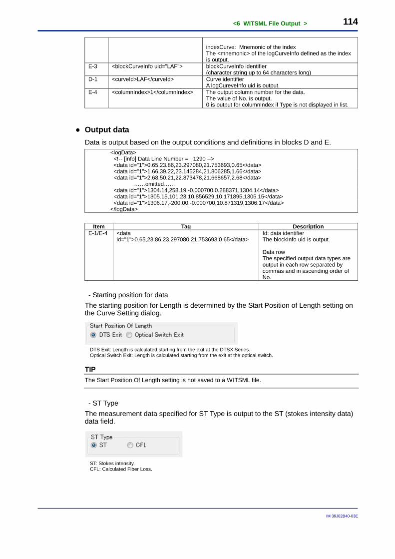
<6 WITSML File Output > 114
IM 39J02B40-03E
indexCurve: Mnemonic of the index The <mnemonic> of the logCurveInfo defined as the index is output.
E-3 <blockCurveInfo uid="LAF"> blockCurveInfo identifier (character string up to 64 characters long)
D-1 <curveId>LAF</curveId> Curve identifier A logCureveInfo uid is output.
E-4 <columnIndex>1</columnIndex> The output column number for the data. The value of No. is output. 0 is output for columnIndex if Type is not displayed in list.
● Output data Data is output based on the output conditions and definitions in blocks D and E.
<logData> <!-- [info] Data Line Number = 1290 --> <data id="1">0.65,23.86,23.297080,21.753693,0.65</data> <data id="1">1.66,39.22,23.145284,21.806285,1.66</data> <data id="1">2.68,50.21,22.873478,21.668657,2.68</data> ……omitted…… <data id="1">1304.14,258.19,-0.000700,0.288371,1304.14</data> <data id="1">1305.15,101.23,10.856529,10.171895,1305.15</data> <data id="1">1306.17,-200.00,-0.000700,10.871319,1306.17</data> </logData>
Item Tag Description
E-1/E-4 <data id="1">0.65,23.86,23.297080,21.753693,0.65</data>
Id: data identifier The blockInfo uid is output. Data row The specified output data types are output in each row separated by commas and in ascending order of No.
- Starting position for data
The starting position for Length is determined by the Start Position of Length setting on the Curve Setting dialog.
DTS Exit: Length is calculated starting from the exit at the DTSX Series. Optical Switch Exit: Length is calculated starting from the exit at the optical switch.
TIP The Start Position Of Length setting is not saved to a WITSML file.
- ST Type
The measurement data specified for ST Type is output to the ST (stokes intensity data) data field.
ST: Stokes intensity. CFL: Calculated Fiber Loss.
<6 WITSML File Output > 115
IM 39J02B40-03E
TIP - The number of output data varies with the Calculation Range setting. For details on the Calculation Range setting, see Subsection B7.3.1, “Fiber Settings” of the DTSXL Distributed Temperature Sensor Long Range System Guide (IM39J06B40-01E).
- If ST Type is specified as CFL, the following message is output below logData in the output data. <!-- [info] The cfl data is output to the stokes intensity data field. -->
6.3 Executing Data Output After defining the output conditions, you can start measurement. You can also check created measurement data, reported errors and other statuses during measurement.
SEE ALSO For details on remote commands for executing measurement and checking statuses, see the DTSX3000 Communications Guide (IM39J06B40-02E) and Chapter 7, “Modbus Address Map,” of this Guide.
6.4 Measurement Data Output The DTSX Series converts measurement data first into WITSML format files and archives the files in its internal memory. Files are archived continuously in its memory area according to limits on minimum free space and maximum number of files. When the memory area limit is exceeded, the oldest file is deleted and the most recent file is archived. Thus, the memory area of the DTSX Series always contains the most recent files. The DTSX Series assigns a user-specified string and an automatically generated control number as part of the name of each measurement data archive file. This control number is related to the archive directory name.
SEE ALSO See the DTSX3000 Guide (IM39J06B40-01E) for details.
6.5 Retrieving Measurement Data WITSML files stored in the memory area of the DTSX Series can be retrieved externally using SFTP client functions or transferred to an external HTTP server using the HTTP client function of the DTSX Series.
SEE ALSO See the DTSX Series Guide (IM39J06B40-01E) for details.
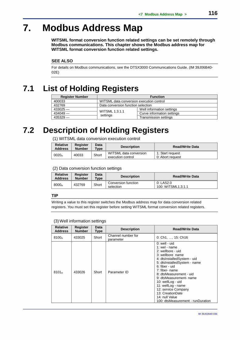
<7 Modbus Address Map > 116
IM 39J02B40-03E
7. Modbus Address Map WITSML format conversion function related settings can be set remotely through Modbus communications. This chapter shows the Modbus address map for WITSML format conversion function related settings.
SEE ALSO For details on Modbus communications, see the DTSX3000 Communications Guide. (IM 39J06B40-02E)
7.1 List of Holding Registers Register Number Function
400033 WITSML data conversion execution control 432769 Data conversion function selection 433025 — WITSML 1.3.1.1
settings
Well information settings 434049 — Curve information settings 435329 — Transmission settings
7.2 Description of Holding Registers (1) WITSML data conversion execution control
Relative Address
Register Number
Data Type Description Read/Write Data
0020H 40033 Short WITSML data conversion execution control
1: Start request 0: Abort request
(2) Data conversion function settings
Relative Address
Register Number
Data Type Description Read/Write Data
8000H 432769 Short Conversion function selection
0: LAS2.0 100: WITSML1.3.1.1
TIP Writing a value to this register switches the Modbus address map for data conversion related registers. You must set this register before setting WITSML format conversion related registers.
(3) Well information settings Relative Address
Register Number
Data Type Description Read/Write Data
8100H 433025 Short Channel number for parameter 0: Ch1, …, 15: Ch16
8101H 433026 Short Parameter ID
0: well - uid 1: wel - name 2: wellbore - uid 3: wellbore name 4: dtsInstalledSystem - uid 5: dtsInstalledSystem - name 6: fiber - uid 7: fiber- name 8: dtsMeasurement - uid 9: dtsMeasurement- name 10: wellLog - uid 11: wellLog - name 12: service Company 13: CreationDate 14: null Value 100: dtsMeasurement - runDuration
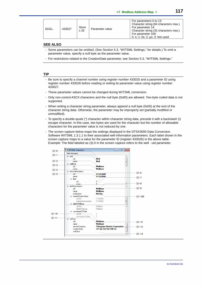
<7 Modbus Address Map > 117
IM 39J02B40-03E
8102H 433027 Short x 33 Parameter value
For parameters 0 to 13: Character string (64 characters max.) For parameter 14: Character string (32 characters max.) For parameter 100: 0: s; 1: 0s; 2: µs; 3: Not used
SEE ALSO - Some parameters can be omitted. (See Section 5.3, “WITSML Settings,” for details.) To omit a
parameter value, specify a null byte as the parameter value.
- For restrictions related to the CreationDate parameter, see Section 5.3, “WITSML Settings.”
TIP - Be sure to specify a channel number using register number 433025 and a parameter ID using
register number 433026 before reading or writing its parameter value using register number 433027.
- These parameter values cannot be changed during WITSML conversion.
- Only non-control ASCII characters and the null byte (0x00) are allowed. Two-byte coded data is not supported.
- When writing a character string parameter, always append a null byte (0x00) at the end of the character string data. Otherwise, the parameter may be improperly set (partially modified or unmodified).
- To specify a double-quote (“) character within character string data, precede it with a backslash (\) escape character. In this case, two bytes are used for the character but the number of allowable characters for the parameter value is not reduced by one.
- The screen capture below maps the settings displayed in the DTSX3000 Data Conversion Software WITSML 1.3.1.1 to their associated well information parameters. Each label shown in the screen capture maps to a value for the parameter ID (register 433026) in the above table. Example: The field labeled as (3)-0 in the screen capture refers to the well - uid parameter.
(3)-0
(3)-1
(3)-3
(3)-2
(3)-4
(3)-5
(3)-7
(3)-8
(3)-9
(3)-100
(3)-10
(3)-11
(3)-12
(3)-13
(3)-14
(3)-6
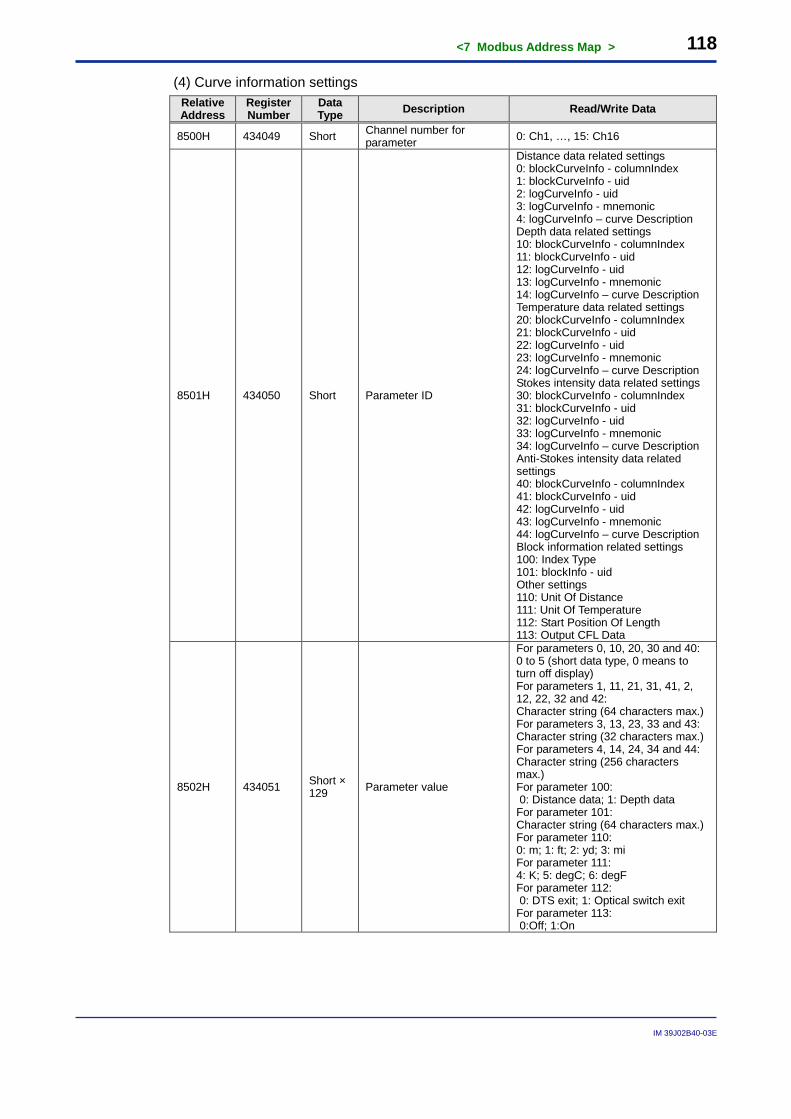
<7 Modbus Address Map > 118
IM 39J02B40-03E
(4) Curve information settings Relative Address
Register Number
Data Type Description Read/Write Data
8500H 434049 Short Channel number for parameter 0: Ch1, …, 15: Ch16
8501H 434050 Short Parameter ID
Distance data related settings 0: blockCurveInfo - columnIndex 1: blockCurveInfo - uid 2: logCurveInfo - uid 3: logCurveInfo - mnemonic 4: logCurveInfo – curve Description Depth data related settings 10: blockCurveInfo - columnIndex 11: blockCurveInfo - uid 12: logCurveInfo - uid 13: logCurveInfo - mnemonic 14: logCurveInfo – curve Description Temperature data related settings 20: blockCurveInfo - columnIndex 21: blockCurveInfo - uid 22: logCurveInfo - uid 23: logCurveInfo - mnemonic 24: logCurveInfo – curve Description Stokes intensity data related settings 30: blockCurveInfo - columnIndex 31: blockCurveInfo - uid 32: logCurveInfo - uid 33: logCurveInfo - mnemonic 34: logCurveInfo – curve Description Anti-Stokes intensity data related settings 40: blockCurveInfo - columnIndex 41: blockCurveInfo - uid 42: logCurveInfo - uid 43: logCurveInfo - mnemonic 44: logCurveInfo – curve Description Block information related settings 100: Index Type 101: blockInfo - uid Other settings 110: Unit Of Distance 111: Unit Of Temperature 112: Start Position Of Length 113: Output CFL Data
8502H 434051 Short × 129 Parameter value
For parameters 0, 10, 20, 30 and 40: 0 to 5 (short data type, 0 means to turn off display) For parameters 1, 11, 21, 31, 41, 2, 12, 22, 32 and 42: Character string (64 characters max.) For parameters 3, 13, 23, 33 and 43: Character string (32 characters max.) For parameters 4, 14, 24, 34 and 44: Character string (256 characters max.) For parameter 100: 0: Distance data; 1: Depth data For parameter 101: Character string (64 characters max.) For parameter 110: 0: m; 1: ft; 2: yd; 3: mi For parameter 111: 4: K; 5: degC; 6: degF For parameter 112: 0: DTS exit; 1: Optical switch exit For parameter 113: 0:Off; 1:On
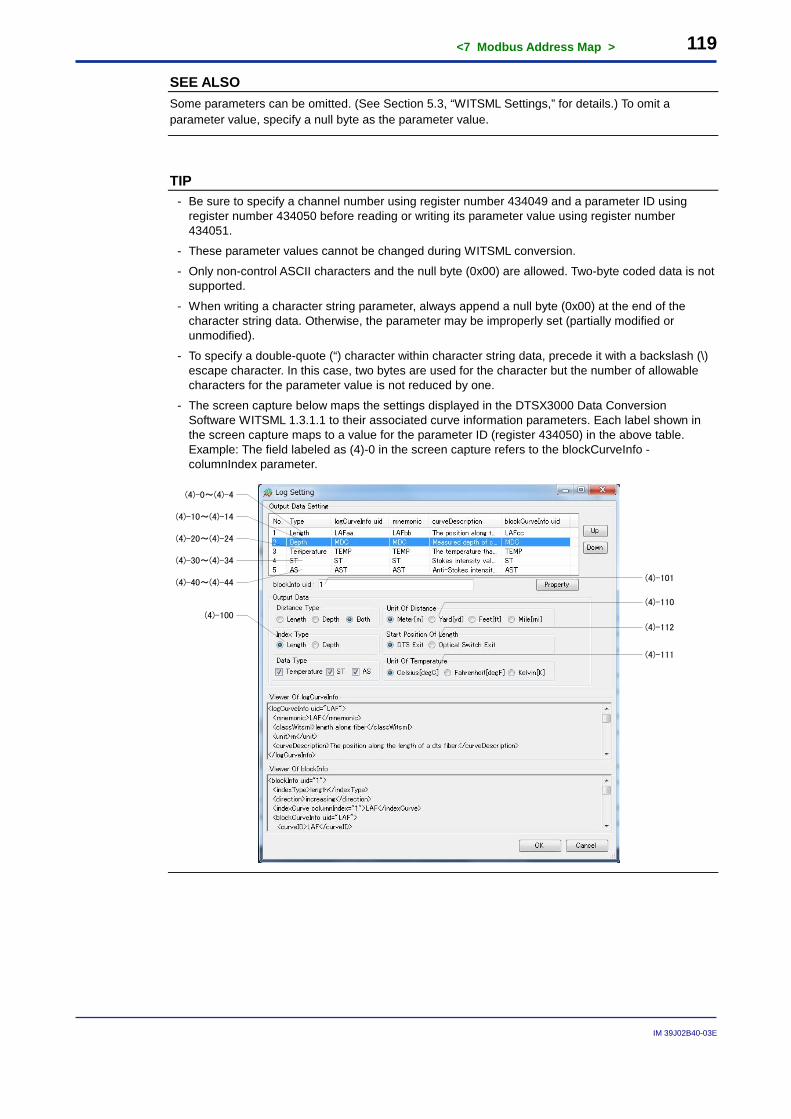
<7 Modbus Address Map > 119
IM 39J02B40-03E
SEE ALSO Some parameters can be omitted. (See Section 5.3, “WITSML Settings,” for details.) To omit a parameter value, specify a null byte as the parameter value.
TIP - Be sure to specify a channel number using register number 434049 and a parameter ID using
register number 434050 before reading or writing its parameter value using register number 434051.
- These parameter values cannot be changed during WITSML conversion.
- Only non-control ASCII characters and the null byte (0x00) are allowed. Two-byte coded data is not supported.
- When writing a character string parameter, always append a null byte (0x00) at the end of the character string data. Otherwise, the parameter may be improperly set (partially modified or unmodified).
- To specify a double-quote (“) character within character string data, precede it with a backslash (\) escape character. In this case, two bytes are used for the character but the number of allowable characters for the parameter value is not reduced by one.
- The screen capture below maps the settings displayed in the DTSX3000 Data Conversion Software WITSML 1.3.1.1 to their associated curve information parameters. Each label shown in the screen capture maps to a value for the parameter ID (register 434050) in the above table. Example: The field labeled as (4)-0 in the screen capture refers to the blockCurveInfo - columnIndex parameter.
(4)-0~(4)-4
(4)-10~(4)-14
(4)-20~(4)-24
(4)-30~(4)-34
(4)-40~(4)-44 (4)-101
(4)-100
(4)-110
(4)-112
(4)-111
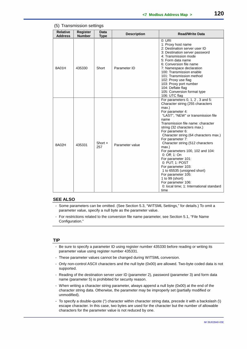
<7 Modbus Address Map > 120
IM 39J02B40-03E
(5) Transmission settings Relative Address
Register Number
Data Type Description Read/Write Data
8A01H 435330 Short Parameter ID
0: URI 1: Proxy host name 2: Destination server user ID 3: Destination server password 4: Transmission mode 5: Form data name 6: Conversion file name 7: Namespace declaration 100: Transmission enable 101: Transmission method 102: Proxy use flag 103: Proxy port number 104: Deflate flag 105: Conversion format type 106: UTC flag
8A02H 435331 Short × 257 Parameter value
For parameters 0, 1, 2 , 3 and 5: Character string (255 characters max.) For parameter 4: “LAST”, “NEW” or transmission file name Transmission file name: character string (32 characters max.) For parameter 6: Character string (64 characters max.) For parameter 7: Character string (512 characters max.) For parameters 100, 102 and 104: 0: Off; 1: On For parameter 101: 0: PUT; 1: POST For parameter 103: 1 to 65535 (unsigned short) For parameter 105: 1 to 99 (short) For parameter 106: 0: local time; 1: International standard time
SEE ALSO - Some parameters can be omitted. (See Section 5.3, “WITSML Settings,” for details.) To omit a
parameter value, specify a null byte as the parameter value.
- For restrictions related to the conversion file name parameter, see Section 5.1, “File Name Configuration.”
TIP - Be sure to specify a parameter ID using register number 435330 before reading or writing its
parameter value using register number 435331.
- These parameter values cannot be changed during WITSML conversion.
- Only non-control ASCII characters and the null byte (0x00) are allowed. Two-byte coded data is not supported.
- Reading of the destination server user ID (parameter 2), password (parameter 3) and form data name (parameter 5) is prohibited for security reason.
- When writing a character string parameter, always append a null byte (0x00) at the end of the character string data. Otherwise, the parameter may be improperly set (partially modified or unmodified).
- To specify a double-quote (“) character within character string data, precede it with a backslash (\) escape character. In this case, two bytes are used for the character but the number of allowable characters for the parameter value is not reduced by one.
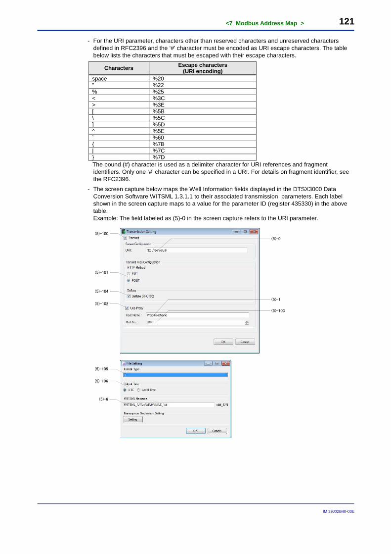
<7 Modbus Address Map > 121
IM 39J02B40-03E
- For the URI parameter, characters other than reserved characters and unreserved characters defined in RFC2396 and the ‘#’ character must be encoded as URI escape characters. The table below lists the characters that must be escaped with their escape characters.
Characters Escape characters (URI encoding)
space %20 " %22 % %25 < %3C > %3E [ %5B \ %5C ] %5D ^ %5E ` %60 { %7B | %7C } %7D
The pound (#) character is used as a delimiter character for URI references and fragment identifiers. Only one ‘#’ character can be specified in a URI. For details on fragment identifier, see the RFC2396.
- The screen capture below maps the Well Information fields displayed in the DTSX3000 Data Conversion Software WITSML 1.3.1.1 to their associated transmission parameters. Each label shown in the screen capture maps to a value for the parameter ID (register 435330) in the above table. Example: The field labeled as (5)-0 in the screen capture refers to the URI parameter.
(5)-100
(5)-101
(5)-104
(5)-102
(5)-0
(5)-1
(5)-103
(5)-105
(5)-106
(5)-6
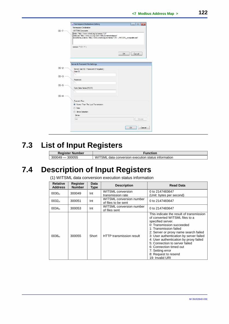
<7 Modbus Address Map > 122
IM 39J02B40-03E
(5)-7
(5)-2
(5)-3
(5)-5
(5)-4
7.3 List of Input Registers Register Number Function
300049 — 300055 WITSML data conversion execution status information
7.4 Description of Input Registers (1) WITSML data conversion execution status information
Relative Address
Register Number
Data Type Description Read Data
0030H 300049 Int WITSML conversion transmission rate
0 to 2147483647 (Unit: bytes per second)
0032H 300051 Int WITSML conversion number of files to be sent 0 to 2147483647
0034H 300053 Int WITSML conversion number of files sent 0 to 2147483647
0036H 300055 Short HTTP transmission result
This indicate the result of transmission of converted WITSML files to a specified server. 0: Transmission succeeded 1: Transmission failed 2: Server or proxy name search failed 3: User authentication by server failed 4: User authentication by proxy failed 5: Connection to server failed 6: Connection timed out 7: Setting error 8: Request to resend 19: Invalid URI
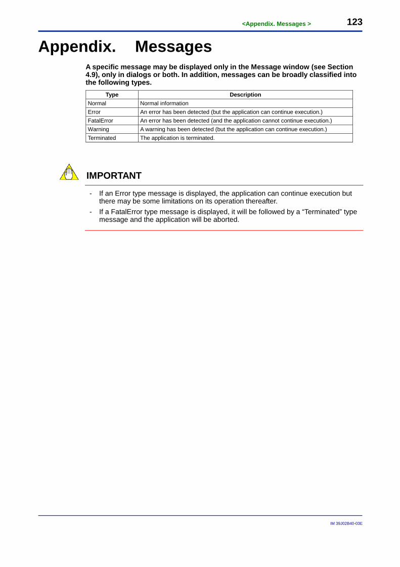
<Appendix. Messages > 123
IM 39J02B40-03E
Appendix. Messages A specific message may be displayed only in the Message window (see Section 4.9), only in dialogs or both. In addition, messages can be broadly classified into the following types.
Type Description Normal Normal information Error An error has been detected (but the application can continue execution.) FatalError An error has been detected (and the application cannot continue execution.) Warning A warning has been detected (but the application can continue execution.) Terminated The application is terminated.
IMPORTANT
- If an Error type message is displayed, the application can continue execution but there may be some limitations on its operation thereafter.
- If a FatalError type message is displayed, it will be followed by a “Terminated” type message and the application will be aborted.
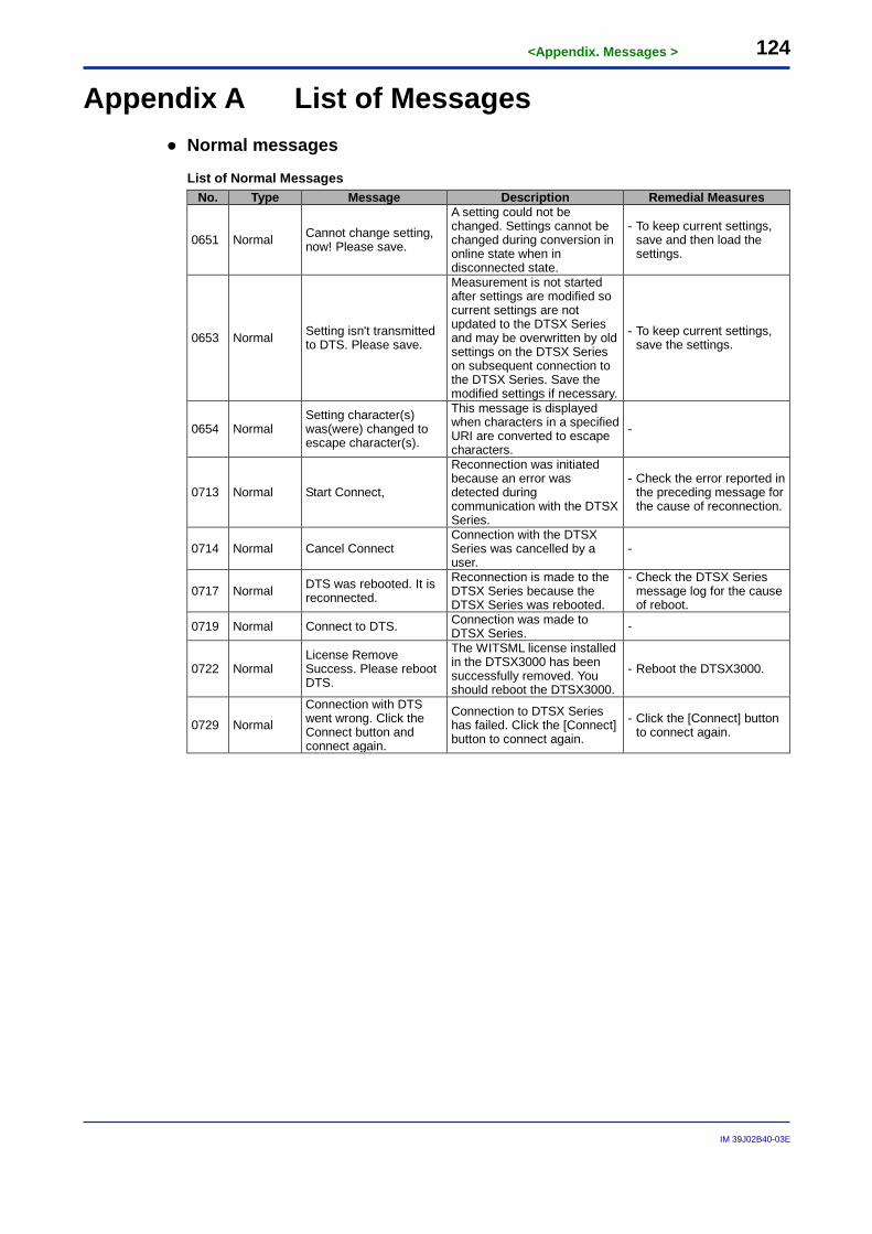
<Appendix. Messages > 124
IM 39J02B40-03E
Appendix A List of Messages ● Normal messages
List of Normal Messages No. Type Message Description Remedial Measures
0651 Normal Cannot change setting, now! Please save.
A setting could not be changed. Settings cannot be changed during conversion in online state when in disconnected state.
- To keep current settings, save and then load the settings.
0653 Normal Setting isn't transmitted to DTS. Please save.
Measurement is not started after settings are modified so current settings are not updated to the DTSX Series and may be overwritten by old settings on the DTSX Series on subsequent connection to the DTSX Series. Save the modified settings if necessary.
- To keep current settings, save the settings.
0654 Normal Setting character(s) was(were) changed to escape character(s).
This message is displayed when characters in a specified URI are converted to escape characters.
-
0713 Normal Start Connect,
Reconnection was initiated because an error was detected during communication with the DTSX Series.
- Check the error reported in the preceding message for the cause of reconnection.
0714 Normal Cancel Connect Connection with the DTSX Series was cancelled by a user.
-
0717 Normal DTS was rebooted. It is reconnected.
Reconnection is made to the DTSX Series because the DTSX Series was rebooted.
- Check the DTSX Series message log for the cause of reboot.
0719 Normal Connect to DTS. Connection was made to DTSX Series. -
0722 Normal License Remove Success. Please reboot DTS.
The WITSML license installed in the DTSX3000 has been successfully removed. You should reboot the DTSX3000.
- Reboot the DTSX3000.
0729 Normal Connection with DTS went wrong. Click the Connect button and connect again.
Connection to DTSX Series has failed. Click the [Connect] button to connect again.
- Click the [Connect] button to connect again.
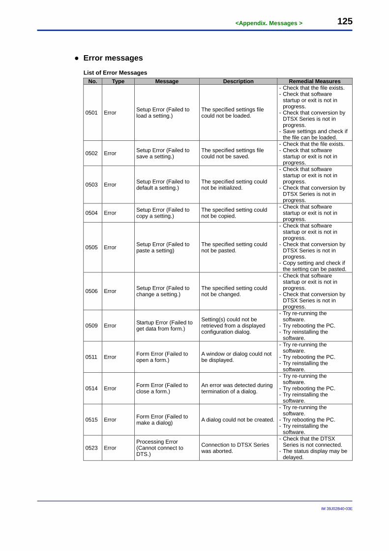
<Appendix. Messages > 125
IM 39J02B40-03E
● Error messages
List of Error Messages No. Type Message Description Remedial Measures
0501 Error Setup Error (Failed to load a setting.)
The specified settings file could not be loaded.
- Check that the file exists. - Check that software
startup or exit is not in progress.
- Check that conversion by DTSX Series is not in progress.
- Save settings and check if the file can be loaded.
0502 Error Setup Error (Failed to save a setting.)
The specified settings file could not be saved.
- Check that the file exists. - Check that software
startup or exit is not in progress.
0503 Error Setup Error (Failed to default a setting.)
The specified setting could not be initialized.
- Check that software startup or exit is not in progress.
- Check that conversion by DTSX Series is not in progress.
0504 Error Setup Error (Failed to copy a setting.)
The specified setting could not be copied.
- Check that software startup or exit is not in progress.
0505 Error Setup Error (Failed to paste a setting)
The specified setting could not be pasted.
- Check that software startup or exit is not in progress.
- Check that conversion by DTSX Series is not in progress.
- Copy setting and check if the setting can be pasted.
0506 Error Setup Error (Failed to change a setting.)
The specified setting could not be changed.
- Check that software startup or exit is not in progress.
- Check that conversion by DTSX Series is not in progress.
0509 Error Startup Error (Failed to get data from form.)
Setting(s) could not be retrieved from a displayed configuration dialog.
- Try re-running the software.
- Try rebooting the PC. - Try reinstalling the
software.
0511 Error Form Error (Failed to open a form.)
A window or dialog could not be displayed.
- Try re-running the software.
- Try rebooting the PC. - Try reinstalling the
software.
0514 Error Form Error (Failed to close a form.)
An error was detected during termination of a dialog.
- Try re-running the software.
- Try rebooting the PC. - Try reinstalling the
software.
0515 Error Form Error (Failed to make a dialog) A dialog could not be created.
- Try re-running the software.
- Try rebooting the PC. - Try reinstalling the
software.
0523 Error Processing Error (Cannot connect to DTS.)
Connection to DTSX Series was aborted.
- Check that the DTSX Series is not connected.
- The status display may be delayed.
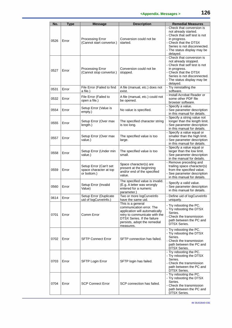
<Appendix. Messages > 126
IM 39J02B40-03E
No. Type Message Description Remedial Measures
0526 Error Processing Error (Cannot start convertor.)
Conversion could not be started.
- Check that conversion is not already started.
- Check that self test is not in progress.
- Check that the DTSX Series is not disconnected.
- The status display may be delayed.
0527 Error Processing Error (Cannot stop convertor.)
Conversion could not be stopped.
- Check that conversion is not already stopped.
- Check that self test is not in progress.
- Check that the DTSX Series is not disconnected.
- The status display may be delayed.
0531 Error File Error (Failed to find a file.)
A file (manual, etc.) does not exist.
- Try reinstalling the software.
0532 Error File Error (Failed to open a file.)
A file (manual, etc.) could not be opened.
- Install Acrobat Reader or some other PDF file browser software.
0554 Error Setup Error (Value is empty.) No value is specified.
- Specify a value. - See parameter description
in this manual for details.
0555 Error Setup Error (Over max length.)
The specified character string is too long.
- Specify a string value not longer than the length limit.
- See parameter description in this manual for details.
0557 Error Setup Error (Over max value.)
The specified value is too large.
- Specify a value equal or smaller than the high limit.
- See parameter description in this manual for details.
0558 Error Setup Error (Under min value.)
The specified value is too small.
- Specify a value equal or larger than the low limit.
- See parameter description in the manual for details.
0559 Error Setup Error (Can't set space character at top or bottom.)
Space character(s) are present at the beginning and/or end of the specified value.
- Remove preceding and trailing space character(s) from the specified value.
- See parameter description in this manual for details.
0560 Error Setup Error (Invalid Value)
The specified value is invalid. (E.g. A letter was wrongly entered for a numeric parameter.)
- Specify a valid value. - See parameter description
in this manual for details.
0614 Error Setup Error (Duplicate uid of logCurveInfo.)
Two or more logCurveInfo have the same uid.
- Define uid of logCurveInfo uniquely.
0701 Error Comm Error
This is a general communication error. The application will automatically retry to communicate with the DTSX Series. If the failure persists, adopt the remedial measures.
- Try rebooting the PC. - Try rebooting the DTSX
Series. - Check the transmission
path between the PC and DTSX Series.
0702 Error SFTP Connect Error SFTP connection has failed.
- Try rebooting the PC. - Try rebooting the DTSX
Series. - Check the transmission
path between the PC and DTSX Series.
0703 Error SFTP Login Error SFTP login has failed.
- Try rebooting the PC. - Try rebooting the DTSX
Series. - Check the transmission
path between the PC and DTSX Series.
0704 Error SCP Connect Error SCP connection has failed.
- Try rebooting the PC. - Try rebooting the DTSX
Series. - Check the transmission
path between the PC and DTSX Series.
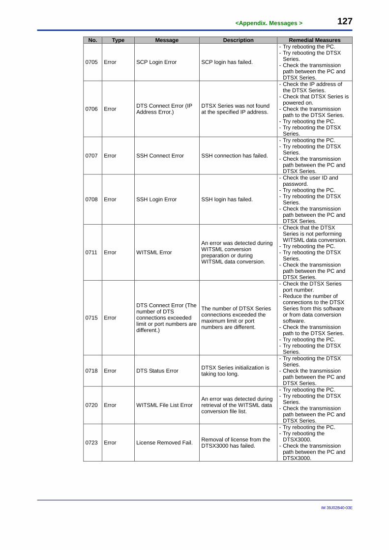
<Appendix. Messages > 127
IM 39J02B40-03E
No. Type Message Description Remedial Measures
0705 Error SCP Login Error SCP login has failed.
- Try rebooting the PC. - Try rebooting the DTSX
Series. - Check the transmission
path between the PC and DTSX Series.
0706 Error DTS Connect Error (IP Address Error.)
DTSX Series was not found at the specified IP address.
- Check the IP address of the DTSX Series.
- Check that DTSX Series is powered on.
- Check the transmission path to the DTSX Series.
- Try rebooting the PC. - Try rebooting the DTSX
Series.
0707 Error SSH Connect Error SSH connection has failed.
- Try rebooting the PC. - Try rebooting the DTSX
Series. - Check the transmission
path between the PC and DTSX Series.
0708 Error SSH Login Error SSH login has failed.
- Check the user ID and password.
- Try rebooting the PC. - Try rebooting the DTSX
Series. - Check the transmission
path between the PC and DTSX Series.
0711 Error WITSML Error
An error was detected during WITSML conversion preparation or during WITSML data conversion.
- Check that the DTSX Series is not performing WITSML data conversion.
- Try rebooting the PC. - Try rebooting the DTSX
Series. - Check the transmission
path between the PC and DTSX Series.
0715 Error
DTS Connect Error (The number of DTS connections exceeded limit or port numbers are different.)
The number of DTSX Series connections exceeded the maximum limit or port numbers are different.
- Check the DTSX Series port number.
- Reduce the number of connections to the DTSX Series from this software or from data conversion software.
- Check the transmission path to the DTSX Series.
- Try rebooting the PC. - Try rebooting the DTSX
Series.
0718 Error DTS Status Error DTSX Series initialization is taking too long.
- Try rebooting the DTSX Series.
- Check the transmission path between the PC and DTSX Series.
0720 Error WITSML File List Error An error was detected during retrieval of the WITSML data conversion file list.
- Try rebooting the PC. - Try rebooting the DTSX
Series. - Check the transmission
path between the PC and DTSX Series.
0723 Error License Removed Fail. Removal of license from the DTSX3000 has failed.
- Try rebooting the PC. - Try rebooting the
DTSX3000. - Check the transmission
path between the PC and DTSX3000.
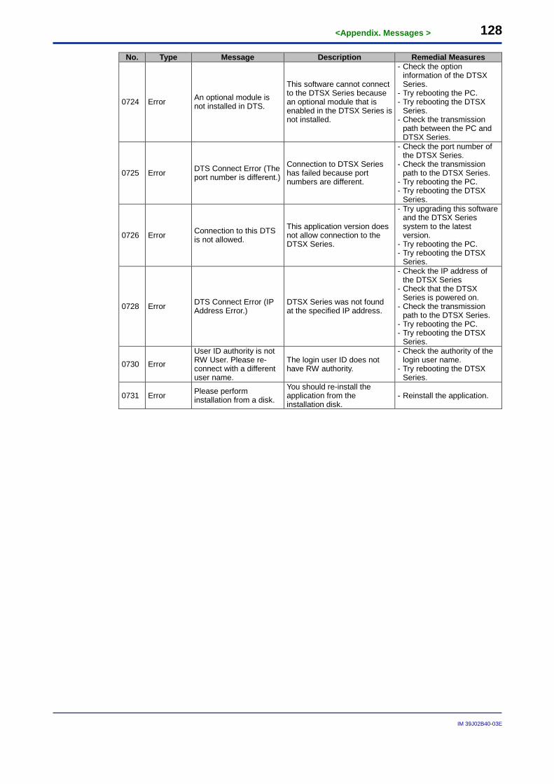
<Appendix. Messages > 128
IM 39J02B40-03E
No. Type Message Description Remedial Measures
0724 Error An optional module is not installed in DTS.
This software cannot connect to the DTSX Series because an optional module that is enabled in the DTSX Series is not installed.
- Check the option information of the DTSX Series.
- Try rebooting the PC. - Try rebooting the DTSX
Series. - Check the transmission
path between the PC and DTSX Series.
0725 Error DTS Connect Error (The port number is different.)
Connection to DTSX Series has failed because port numbers are different.
- Check the port number of the DTSX Series.
- Check the transmission path to the DTSX Series.
- Try rebooting the PC. - Try rebooting the DTSX
Series.
0726 Error Connection to this DTS is not allowed.
This application version does not allow connection to the DTSX Series.
- Try upgrading this software and the DTSX Series system to the latest version.
- Try rebooting the PC. - Try rebooting the DTSX
Series.
0728 Error DTS Connect Error (IP Address Error.)
DTSX Series was not found at the specified IP address.
- Check the IP address of the DTSX Series
- Check that the DTSX Series is powered on.
- Check the transmission path to the DTSX Series.
- Try rebooting the PC. - Try rebooting the DTSX
Series.
0730 Error User ID authority is not RW User. Please re-connect with a different user name.
The login user ID does not have RW authority.
- Check the authority of the login user name.
- Try rebooting the DTSX Series.
0731 Error Please perform installation from a disk.
You should re-install the application from the installation disk.
- Reinstall the application.
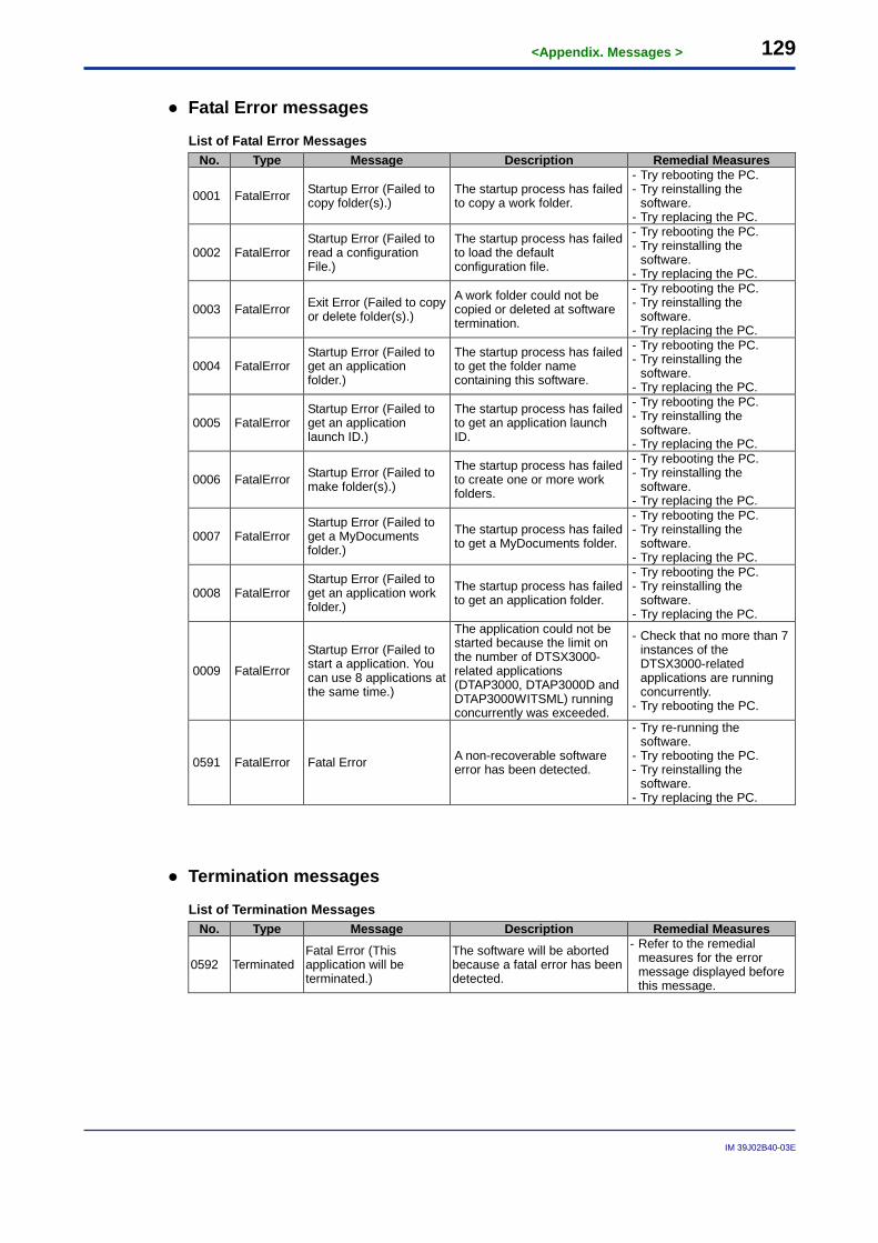
<Appendix. Messages > 129
IM 39J02B40-03E
● Fatal Error messages
List of Fatal Error Messages No. Type Message Description Remedial Measures
0001 FatalError Startup Error (Failed to copy folder(s).)
The startup process has failed to copy a work folder.
- Try rebooting the PC. - Try reinstalling the
software. - Try replacing the PC.
0002 FatalError Startup Error (Failed to read a configuration File.)
The startup process has failed to load the default configuration file.
- Try rebooting the PC. - Try reinstalling the
software. - Try replacing the PC.
0003 FatalError Exit Error (Failed to copy or delete folder(s).)
A work folder could not be copied or deleted at software termination.
- Try rebooting the PC. - Try reinstalling the
software. - Try replacing the PC.
0004 FatalError Startup Error (Failed to get an application folder.)
The startup process has failed to get the folder name containing this software.
- Try rebooting the PC. - Try reinstalling the
software. - Try replacing the PC.
0005 FatalError Startup Error (Failed to get an application launch ID.)
The startup process has failed to get an application launch ID.
- Try rebooting the PC. - Try reinstalling the
software. - Try replacing the PC.
0006 FatalError Startup Error (Failed to make folder(s).)
The startup process has failed to create one or more work folders.
- Try rebooting the PC. - Try reinstalling the
software. - Try replacing the PC.
0007 FatalError Startup Error (Failed to get a MyDocuments folder.)
The startup process has failed to get a MyDocuments folder.
- Try rebooting the PC. - Try reinstalling the
software. - Try replacing the PC.
0008 FatalError Startup Error (Failed to get an application work folder.)
The startup process has failed to get an application folder.
- Try rebooting the PC. - Try reinstalling the
software. - Try replacing the PC.
0009 FatalError
Startup Error (Failed to start a application. You can use 8 applications at the same time.)
The application could not be started because the limit on the number of DTSX3000-related applications (DTAP3000, DTAP3000D and DTAP3000WITSML) running concurrently was exceeded.
- Check that no more than 7 instances of the DTSX3000-related applications are running concurrently.
- Try rebooting the PC.
0591 FatalError Fatal Error A non-recoverable software error has been detected.
- Try re-running the software.
- Try rebooting the PC. - Try reinstalling the
software. - Try replacing the PC.
● Termination messages
List of Termination Messages No. Type Message Description Remedial Measures
0592 Terminated Fatal Error (This application will be terminated.)
The software will be aborted because a fatal error has been detected.
- Refer to the remedial measures for the error message displayed before this message.
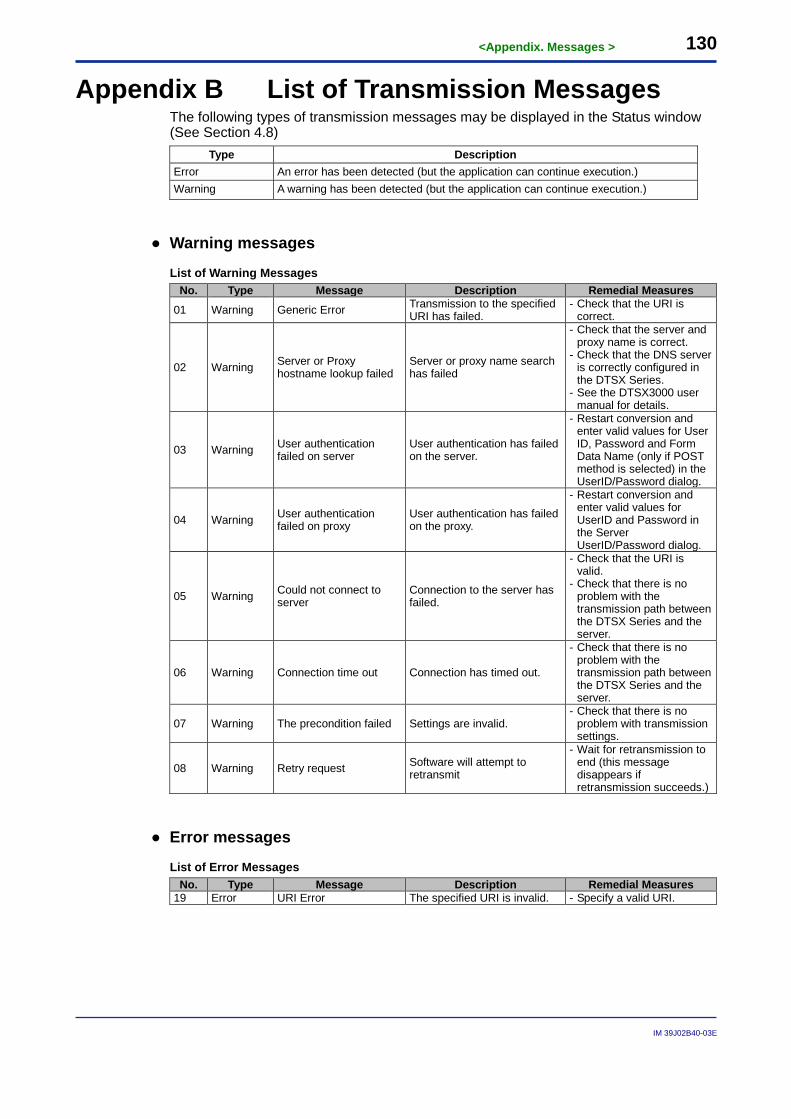
<Appendix. Messages > 130
IM 39J02B40-03E
Appendix B List of Transmission Messages The following types of transmission messages may be displayed in the Status window (See Section 4.8)
Type Description Error An error has been detected (but the application can continue execution.) Warning A warning has been detected (but the application can continue execution.)
● Warning messages
List of Warning Messages No. Type Message Description Remedial Measures
01 Warning Generic Error Transmission to the specified URI has failed.
- Check that the URI is correct.
02 Warning Server or Proxy hostname lookup failed
Server or proxy name search has failed
- Check that the server and proxy name is correct.
- Check that the DNS server is correctly configured in the DTSX Series.
- See the DTSX3000 user manual for details.
03 Warning User authentication failed on server
User authentication has failed on the server.
- Restart conversion and enter valid values for User ID, Password and Form Data Name (only if POST method is selected) in the UserID/Password dialog.
04 Warning User authentication failed on proxy
User authentication has failed on the proxy.
- Restart conversion and enter valid values for UserID and Password in the Server UserID/Password dialog.
05 Warning Could not connect to server
Connection to the server has failed.
- Check that the URI is valid.
- Check that there is no problem with the transmission path between the DTSX Series and the server.
06 Warning Connection time out Connection has timed out.
- Check that there is no problem with the transmission path between the DTSX Series and the server.
07 Warning The precondition failed Settings are invalid. - Check that there is no
problem with transmission settings.
08 Warning Retry request Software will attempt to retransmit
- Wait for retransmission to end (this message disappears if retransmission succeeds.)
● Error messages
List of Error Messages No. Type Message Description Remedial Measures
19 Error URI Error The specified URI is invalid. - Specify a valid URI.
i
IM 39J02B40-03E
Revision Information Title : DTAP3000D DTSX3000 Data Conversion Software WITSML1.3.1.1 Guide Manual No. : IM 39J02B40-03E Oct. 2014/1st Edition/R1.01.01 or later - First published
* : Denotes the release number of the software corresponding to the contents of this instruction manual. The revised contents are valid until the next edition is issued.
Written by Fiber Sensing Department New Field Development Center Industrial Automation Platform Business Headquarters
Yokogawa Electric Corporation Published by Yokogawa Electric Corporation 2-9-32 Nakacho, Musashino-shi, Tokyo 180-8750, Japan Printed by Kohoku Publishing & Printing Inc.