using of meteosat second generation high resolution visible data for the impovement of the rapid...
TRANSCRIPT

USING OF METEOSAT SECOND USING OF METEOSAT SECOND GENERATION HIGH RESOLUTION VISIBLE GENERATION HIGH RESOLUTION VISIBLE
DATA FOR THE IMPOVEMENT OF THE DATA FOR THE IMPOVEMENT OF THE RAPID DEVELOPPING THUNDERSTORM RAPID DEVELOPPING THUNDERSTORM
PRODUCTPRODUCT
Oleksiy KryvobokOleksiy KryvobokUkrainian HydroMeteorological InstituteUkrainian HydroMeteorological Institute
Kyiv, UkraineKyiv, UkraineStephane SenesiStephane Senesi
Meteo-France, DPREVI/PIMeteo-France, DPREVI/PIToulouse, FranceToulouse, FranceChristophe MorelChristophe Morel
Meteo-France, DPREVI/PIMeteo-France, DPREVI/PIToulouse, FranceToulouse, France

The RDT product is an object – oriented diagnostic which provides support to forecasters for real time analysis and automatic warnings of convection. It is produced by RDT software, which use as input data infrared images of the 10.8 (IR10.8) channel of geostationary satellite. Brightness temperature field measured by satellite is used in RDT product for description of convective objects with relevant properties (size, movement, minimum temperature, cooling rates area extentsion rate). See poster of Frederic Autones.

The spatial resolution of one of the MSG channels, the High The spatial resolution of one of the MSG channels, the High Resolution Visible channel (HRVIS), is 1 km at sub-satellite Resolution Visible channel (HRVIS), is 1 km at sub-satellite point (against 3 km for the others channels). This should allow point (against 3 km for the others channels). This should allow the HRVIS channel to describe smaller clouds than the IR10.8 the HRVIS channel to describe smaller clouds than the IR10.8 channel and improve an earliness of first detection of channel and improve an earliness of first detection of convective systems during their growing phase in order to be convective systems during their growing phase in order to be able to warn and provide information to forecaster when able to warn and provide information to forecaster when severe weather may occur.severe weather may occur.
channelchannel Band Band channel typechannel type
Nominal Centre wavelength (μm)
Spectral Spectral Bandwidth Bandwidth (μm)
Spatial resolution at Spatial resolution at SSP, SSP, (km)
HRVHRV Visible High Visible High ResolutionResolution
0.750.75 0.6 – 0.90.6 – 0.9 11

CLOUD FRACTION ESTIMATION CLOUD FRACTION ESTIMATION USING VISIBLE DATAUSING VISIBLE DATA
RRVISVIS=N=N RRcc +(1-N)+(1-N)RRclearclear
where where RRVISVIS - measured reflectance, R- measured reflectance, Rcc - top of atmosphere (TOA) reflectance - top of atmosphere (TOA) reflectance
of cloud,of cloud, R Rclearclear- TOA reflectance of clear sky surface- TOA reflectance of clear sky surface
clearc
clearvis
RR
RRN

Clear sky pixel TOA reflectanceClear sky pixel TOA reflectance
CP
Domain around the Cloudy Pixel (CP) where satellite and sun angles are almost constant.
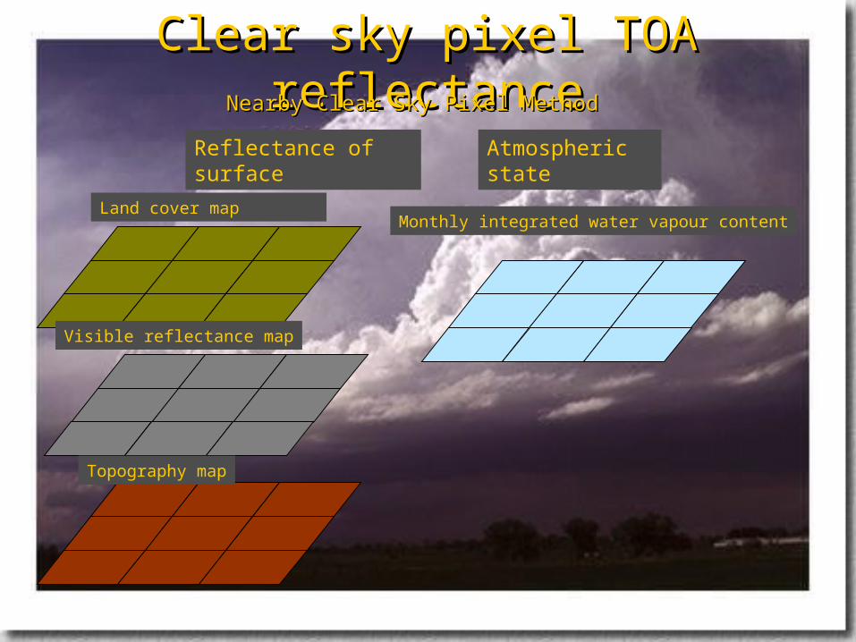
Nearby Clear Sky Pixel MethodNearby Clear Sky Pixel Method
Clear sky pixel TOA reflectanceClear sky pixel TOA reflectance
Reflectance of surface Atmospheric state
Land cover map
Visible reflectance map
Topography map
Monthly integrated water vapour content
Nearby Clear Sky Pixel MethodNearby Clear Sky Pixel Method

Clear sky pixel TOA reflectanceClear sky pixel TOA reflectance
Figure. Example of defining of PoI for cloudy pixels of one convective system. White arrows show the location of corresponding PoI on VIS0.6 image at 11:30 UTC on 4
July 2004.
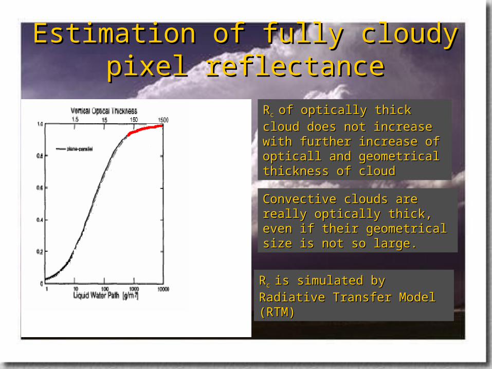
Estimation of fully cloudy pixel Estimation of fully cloudy pixel reflectancereflectance
Convective clouds are really optically Convective clouds are really optically thick, even if their geometrical size is thick, even if their geometrical size is not so large.not so large.
RRc c is simulated by Radiative Transfer is simulated by Radiative Transfer
Model (RTM)Model (RTM)
RRc c of optically thick cloud does not of optically thick cloud does not
increase with further increase of increase with further increase of opticall and geometrical thickness of opticall and geometrical thickness of cloud cloud

Cloudy pixels diagnostic on visible Cloudy pixels diagnostic on visible channelschannels
Threshold technique for cloudy pixel diagnostic.Threshold technique for cloudy pixel diagnostic.
It is relatively easy to adapt thresholds to varying meteorological It is relatively easy to adapt thresholds to varying meteorological conditions, viewing geometry and using external data (NWP data, RTM conditions, viewing geometry and using external data (NWP data, RTM calculation, climatological atlas).calculation, climatological atlas).
According to the Wielicki and Parker (1992) the reflectance threshold in According to the Wielicki and Parker (1992) the reflectance threshold in visible channels is the most sensitive for low (young convective) clouds visible channels is the most sensitive for low (young convective) clouds identificationidentification
These thresholds are calculated using RTM depending on different These thresholds are calculated using RTM depending on different atmospheric states, viewing geometry and different kind of surfaces.atmospheric states, viewing geometry and different kind of surfaces.
Add TOA reflectance a pre-defined margin (to account for noise and Add TOA reflectance a pre-defined margin (to account for noise and variation of surface reflectance).variation of surface reflectance).

Cloudy pixels diagnostic on visible Cloudy pixels diagnostic on visible channelschannels
Figure. Example of cloudy pixel detection on HRVIS image using threshold method. Cloudy pixels are marked by “X”. HRVIS image at 11:30 UTC on 4 July.

METHODS OF CLOUD FRACTION METHODS OF CLOUD FRACTION ESTIMATION FROM ESTIMATION FROM SEVIRISEVIRI DATA DATA
NNHCFFHCFF=(R=(RHRVISHRVIS – R– Rclearclear__HRVISHRVIS)/(R)/(Rc_HRVISc_HRVIS - R- Rclearclear__HRVISHRVIS))
9/)(9
1,
i
iHCFFCCFF NN
NLCFF=(R0.6-Rclear_0.6)/(Rc_0.6–Rclear_0.6)
NLCFF=(R0.8-Rclear_0.8)/(Rc_0.8–Rclear_0.8)

Rapid developing thunderstorm (4 July Rapid developing thunderstorm (4 July 2005, North Africa)2005, North Africa)

DESCRIPTION OF CLOUD DESCRIPTION OF CLOUD CONVECTIVE SYSTEMSCONVECTIVE SYSTEMS
I II
11:00
11:15
11:30 first detection on RDT product (I)
11:45 I

12:00
12:15 first detection on RDT product (II)
II

ANALYSIS OF CLOUD FRACTION ANALYSIS OF CLOUD FRACTION FIELDFIELD
Retrieved cloud fraction fields, superimposed on HRVIS image at 11:15 UTC on 4 July 2004: HCFF (convective system I)

ANALYSIS OF CLOUD FRACTION ANALYSIS OF CLOUD FRACTION FIELDFIELD
Retrieved cloud fraction fields, superimposed on VIS0.6 image at 11:15 UTC on 4 July 2004: CCFF (convective system I)

ANALYSIS OF CLOUD FRACTION ANALYSIS OF CLOUD FRACTION FIELDFIELD
Retrieved cloud fraction fields, superimposed on VIS0.6 image at 11:15 UTC on 4 July 2004: LCFF (convective system I)

ANALYSIS OF CLOUD FRACTION ANALYSIS OF CLOUD FRACTION FIELDFIELD
Retrieved cloud fraction fields, superimposed on HRVIS image at 11:45 UTC on 4 July 2004: HCFF (convective system II)

ANALYSIS OF CLOUD FRACTION ANALYSIS OF CLOUD FRACTION FIELDFIELD
Retrieved cloud fraction fields, superimposed on HRVIS image at 12:00 UTC on 4 July 2004: HCFF (convective system II)

ANALYSIS OF CLOUD FRACTION ANALYSIS OF CLOUD FRACTION FIELDFIELD
Retrieved cloud fraction fields, superimposed on VIS0.6 image at 11:45 UTC on 4 July 2004: CCFF (convective system II)

ANALYSIS OF CLOUD FRACTION ANALYSIS OF CLOUD FRACTION FIELDFIELD
Retrieved cloud fraction fields, superimposed on VIS0.6 image at 12:00 UTC on 4 July 2004: CCFF (convective system II)

ANALYSIS OF CLOUD FRACTION ANALYSIS OF CLOUD FRACTION FIELDFIELD
Retrieved cloud fraction fields, superimposed on VIS0.6 image at 11:45 UTC on 4 July 2004: LCFF (convective system II)

ANALYSIS OF CLOUD FRACTION ANALYSIS OF CLOUD FRACTION FIELDFIELD
Retrieved cloud fraction fields, superimposed on VIS0.6 image at 12:00 UTC on 4 July 2004: LCFF (convective system II)

CONCLUSIONCONCLUSION
The study shows that cloud fraction of pixels can be an additional feature for The study shows that cloud fraction of pixels can be an additional feature for earlier detection of young convective clouds.earlier detection of young convective clouds.
Cloud fraction of pixel obtained using HRVIS data shows more realistic values.Cloud fraction of pixel obtained using HRVIS data shows more realistic values. In order to achieve a robust estimate of cloud fraction (and eventually cloud top In order to achieve a robust estimate of cloud fraction (and eventually cloud top
temperature) for young convective clouds, a number of points should be further temperature) for young convective clouds, a number of points should be further investigated:investigated:
a) more accurate 3-D radiative transfer for the estimation of fully cloudy a) more accurate 3-D radiative transfer for the estimation of fully cloudy reflectance;reflectance;
b) use of integrated water vapour content from NWP;b) use of integrated water vapour content from NWP; c) usefulness and derivation of a visible reflectance map based HRVIS datac) usefulness and derivation of a visible reflectance map based HRVIS data d) advantages of more detailed microphysical and geometrical models of young d) advantages of more detailed microphysical and geometrical models of young
convective clouds;convective clouds; e) correction for co-registration shift between HRVIS and VIS data.e) correction for co-registration shift between HRVIS and VIS data.

:
www.eumetsat.int/en/area4/saf/internet/vs/vs_report/saf-nwc-iop-mfi-sci-rp-03-v1-0.pdf