using sherlock with flowtherm -...
TRANSCRIPT

Using Sherlock with
Flowtherm
Nathan Blattau, Ph.D.
© 2004 - 2007© 2004 - 2010

o Nathan Blattau, Ph.D. - Senior Vice PresidentHas been involved in the packaging and reliability of electronic equipment for more than ten years. His specialties include best practices in design for reliability, robustness of Pb-free, failure analysis, accelerated test plan development, finite element analysis, solder joint reliability, fracture, and fatigue mechanics of materials.
.
© 2004 - 2007© 2004 - 2010

o User Friendlyo Quicko Flexibleo Flexibleo Intuitiveo Reliable
Sherlock is the only commercial off the shelf software that can predict time to failure of electronics under thermalfailure of electronics under thermal cycling and vibration loads
© 2004 - 2007© 2004 - 2010

Intuitive
Easy-to-locate commandsIndustry terminology (parts list stackup pick & place etc )
© 2004 - 2007© 2004 - 2010
Industry terminology (parts list, stackup, pick & place, etc.)
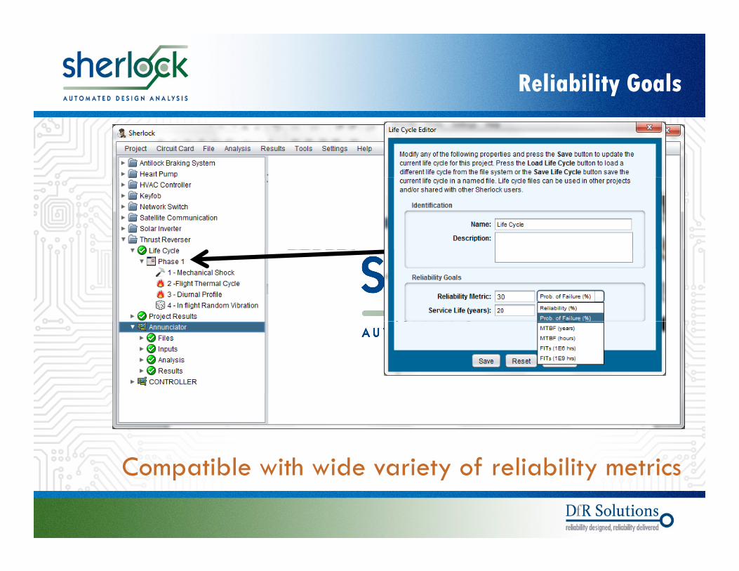
Reliability Goals
Compatible with wide variety of reliability metrics
© 2004 - 2007© 2004 - 2010
Compatible with wide variety of reliability metrics

Ambient Environment
Handles very complex environments
© 2004 - 2007© 2004 - 2010
Handles very complex environments

Input Design Files
Takes standard output files (Gerber / ODB)
© 2004 - 2007© 2004 - 2010
Takes standard output files (Gerber / ODB)
7
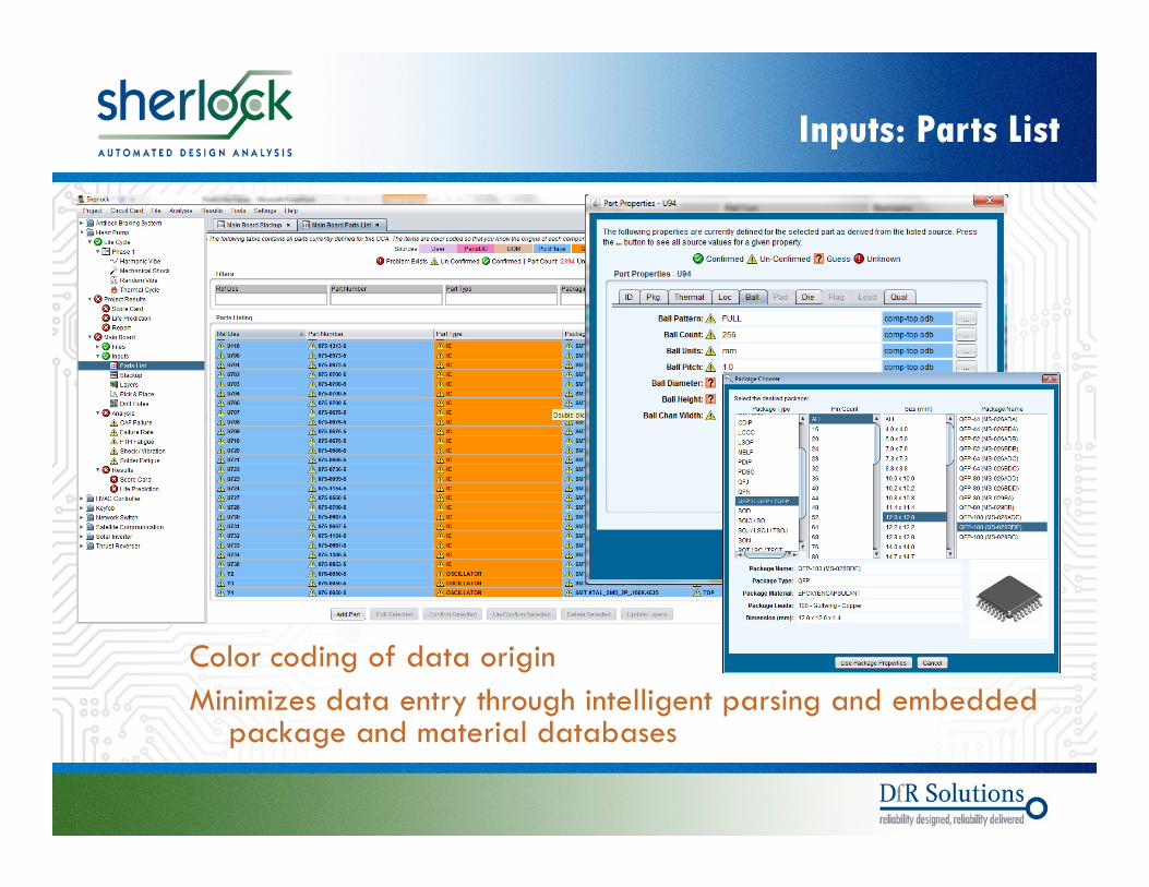
Inputs: Parts List
Color coding of data originMinimizes data entry through intelligent parsing and embedded
k d i l d b
© 2004 - 2007© 2004 - 2010
package and material databases

Inputs: Stackup
Automatically generates stackup and copper percent (%)Embedded database with almost 700 laminate materials
with 48 different properties
© 2004 - 2007© 2004 - 2010
with 48 different properties

Results: Automated Mesh Generation
Identifies optimum mesh density based on board size
E t l i d d l ti d d b 90%
© 2004 - 2007© 2004 - 2010
Expert user no longer required; model time reduced by 90%

o Features in the Sherlocko Global Part Databaseo FEA 3D Model
Sub Assembly Analysiso Sub-Assembly Analysiso FEA 3D Viewero Result Managemento Component lead modeling
© 2004 - 2007© 2004 - 2010
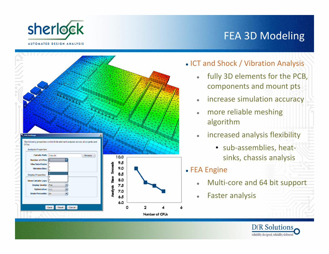
FEA 3D Modeling
ICT and Shock / Vibration Analysis fully 3D elements for the PCB, y ,
components and mount pts increase simulation accuracy
more reliable meshing more reliable meshing algorithm
increased analysis flexibility• sub-assemblies, heat-
sinks, chassis analysis FEA Engine
Multi-core and 64 bit support Faster analysis
© 2004 - 2007© 2004 - 2010

Sub-Assembly Analysis
Attach one or more CCA sub-assemblies to a primary CCAassemblies to a primary CCA
mezzanine cards supported by standoffs
d t d d edge-connected cards
Sherlock automatically analyzes the main CCA and all CCA sub-assemblies during a single ICT or Shock/Vibrationduring a single ICT or Shock/Vibration analysis task
Layer results and component results automatically generated for all circuitautomatically generated for all circuit cards
Edge-connected card
© 2004 - 2007© 2004 - 2010
Edge connected card

Sherlock and Flowtherm
• Flowtherm provides temperatures of the components b t what does that mean forcomponents but what does that mean for reliability?Sh l k l th Fl th l i• Sherlock can leverage the Flowtherm analysis to make better reliability predictions
© 2004 - 2007© 2004 - 2010
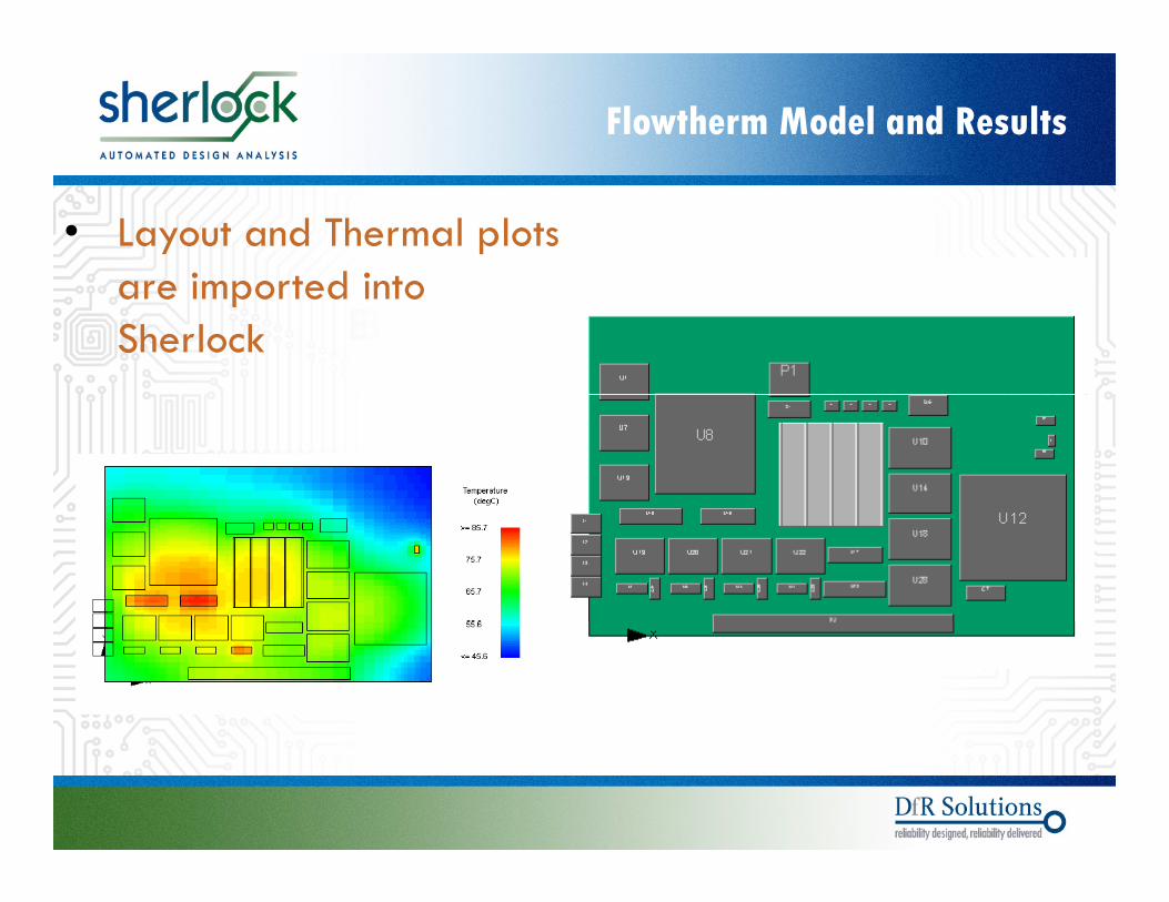
Flowtherm Model and Results
• Layout and Thermal plots are imported intoare imported into Sherlock
© 2004 - 2007© 2004 - 2010
Flowtherm Model and Results
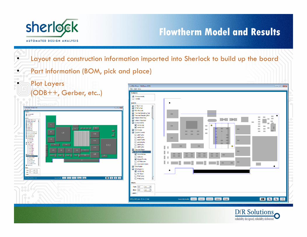
• Layout and construction information imported into Sherlock to build up the board
• Part information (BOM, pick and place)( , p p )
• Plot Layers (ODB++, Gerber, etc..)
© 2004 - 2007© 2004 - 2010

Flowtherm Model and Results
• Layout and Thermal plots are imported intoare imported into Sherlock
3D Sherlock ModelImported Flowtherm Results
© 2004 - 2007© 2004 - 2010
Results
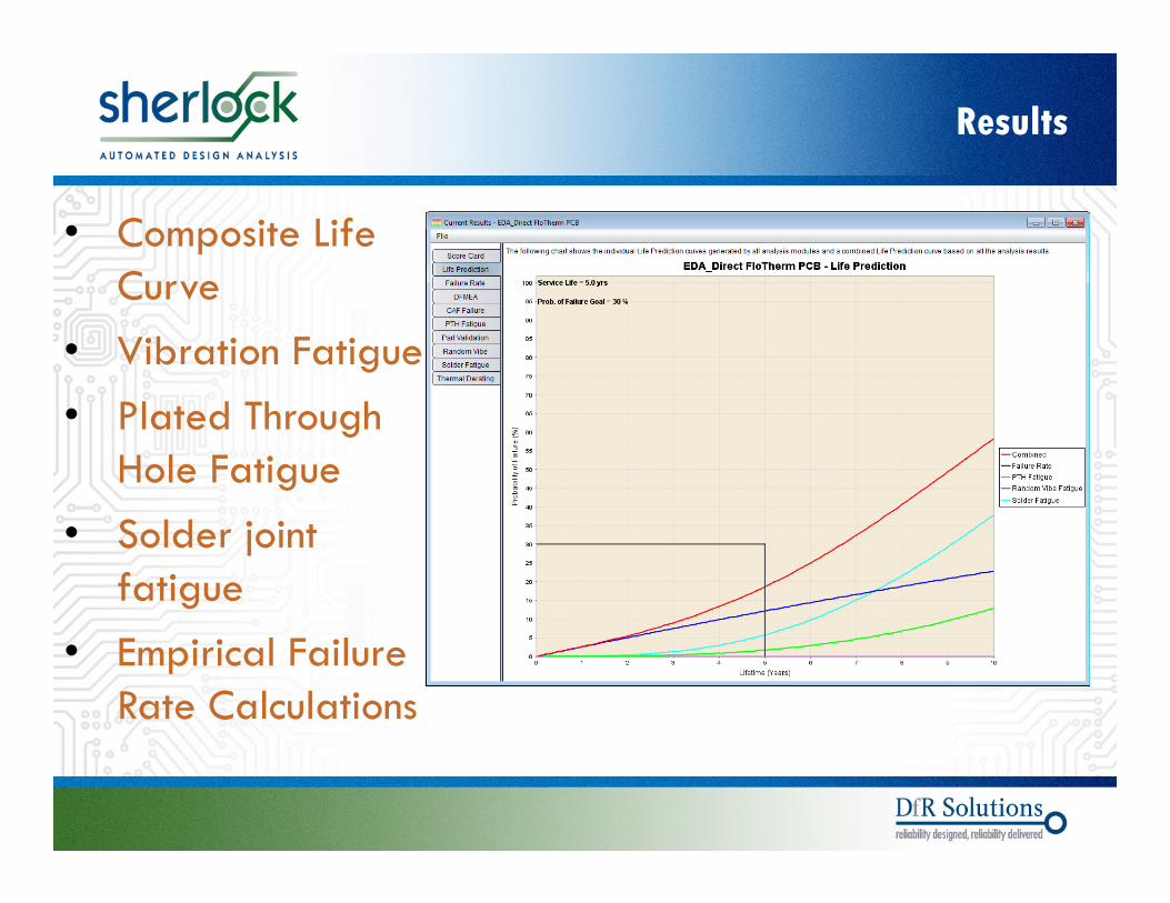
• Composite Life C r eCurve
• Vibration Fatigue• Plated Through
Hole Fatigue• Solder joint
fatigue• Empirical Failure
Rate Calculations
© 2004 - 2007© 2004 - 2010

Vibration Fatigue
• Loading
• Mountingg
• Direction
© 2004 - 2007© 2004 - 2010

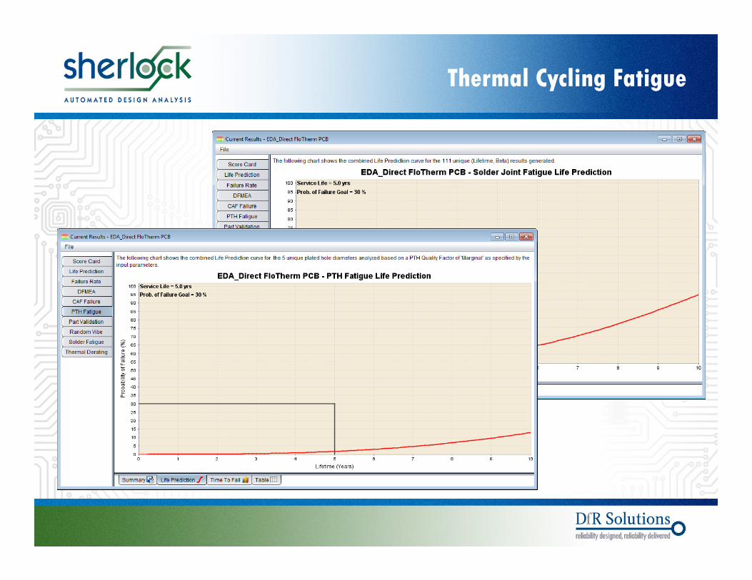
Thermal Cycling Fatigue
• Cumulative Damage Index (CDI)
• Time to failure
• Thermal profile and Flowtherm results
© 2004 - 2007© 2004 - 2010
Thermal Cycling Fatigue
© 2004 - 2007© 2004 - 2010
Results Summary
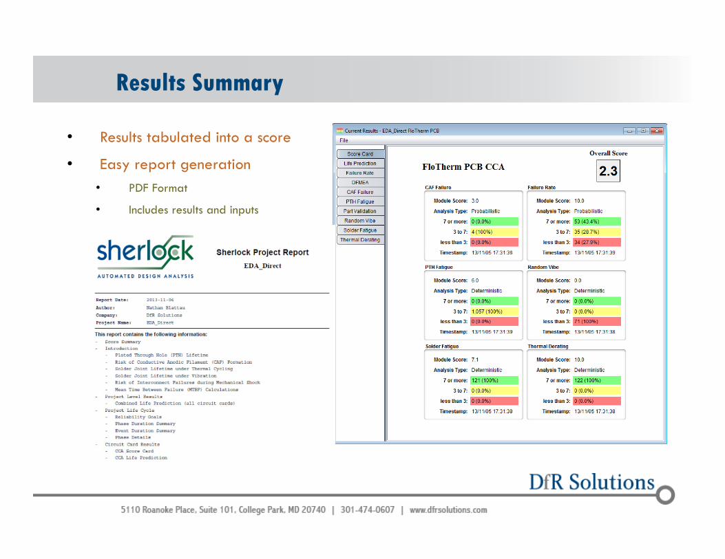
• Results tabulated into a score
• Easy report generation• PDF Format
• Includes results and inputs
© 2004 - 2007© 2004 - 2010

Th k Y !Thank You!
Questions?