utq.edu.iqutq.edu.iq/magazines/docxutq2015/49.docx · web viewin this work a free vibration...
TRANSCRIPT
Journal of University of Thi Qar… Vol. (10)….. No. (2)… June 2015
Dynamic analysis of elevated tanks having various supporting frame configurations
Mawahib A. Gate'a & Dr. Abdulamir Atalla
Department of civil engineering, college of engineering, university of Basrah
ABSTRACT
Liquid storage tanks and especially the elevated tanks are structures of high importance which are
considered as main lifeline elements in modern life. As earthquakes are the most powerful and
dangerous loads that storage tanks may suffer, the vibrated tank with or without a contained liquid is
so critical case so that researchers and designers must give high interest while studying this type of
structures.
In this work a free vibration analysis had been carried out for an empty elevated concrete
cylindrical liquid storage tank supported on a frame consisted of four stories. Four values of height of
the frame are explored; 12, 16, 20 and 24m and four values of column angle of inclination; 0°, 2.38°,
4.76°, 7.125° measured from the vertical are examined. The tanks are modeled by the finite element
method and the analysis is conducted using ANSYS 11. The natural frequency is found to decrease
with increasing in frame height and angle of frame inclination due to stiffness decrement of the
supporting frame.
A forced vibration analysis is also done on a selected case of elevated tank under three filling
percentages: 0%, 50% and 100% .The seismically excited tank has a height of 15.9m and is subjected
to Kocaeli earthquake in Turkey, 1999. The dynamic response including the maximum stresses and
displacements is determined and discussed.
Keywords: Dynamic analysis, seismic loads, elevated storage tank, mode shapes.
1. Introduction
Water tanks are very important structures which supplying water for drinking, firefighting and
other industrial facilities of recent life [1]. The failure of these structures may cause some hazards for
the health of city due to the shortage of water or difficulty in putting out fire during critical conditions
[2]. In the past earthquakes, it has been identified that the collapse of reinforced concrete elevated
tanks under lateral earthquake loads have been extremely susceptible [3], therefore the dynamic
response of liquid storage tanks subjected to earthquakes was a subject of numerous studies in the past
30 years [4].
Omidinasab and Shakib 2008 [2] evaluated the demand of a reinforced concrete elevated water tank
to an ensemble of earthquake records by using linear and nonlinear analysis. They concluded that
1
Journal of University of Thi Qar… Vol. (10)….. No. (2)… June 2015
structure responses for each record depend upon the structure’s dynamic features, the frequency
content and the earthquake characteristics. Lower stages were found to be more vulnerable than upper
stages. Hirde et. al. 2011[5] presented a study of seismic performance of an elevated water tanks for
various seismic zones of India with various heights and capacity of elevated water tanks and for
different soil conditions; They observed that, earthquake forces decreased with increase in staging
height because as staging height increases the structure became more flexible. Therefore time period
increased due to which structural response factor decreases from lower to higher staging height. Patel
et. al. 2012 [4] considered a reinforced elevated water tank supported by fixed base frame type staging
system with different degrees of tapering. They assessed the sloshing response under four earthquake
records for three cases; full, half full and empty. The critical response of elevated tanks may occur in
full condition and also under half condition. The critical response depends on the earthquake
characteristics and particularly frequency content of earthquake records.
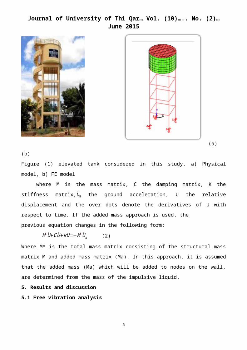
2. Description of the Elevated Tank
A reinforced concrete elevated tank with a container capacity of 50 m3 is considered in the
analysis as used in a previous work [5] (Fig.1). The elevated tank is supported by a hinged base
boundary condition frame structure consisting of four columns with circular cross section of diameter
equal to 450 mm which are connected laterally by rectangular horizontal beams (300*450) mm2 at
heights of 3, 6, 9 and 12m above ground. The vessel is cylindrical with base and cover rigidly
connected with the tanks' walls. The container has a radius of 4.65m and a height of 3.3m. Walls and
floor plate have the same thickness of 200 mm while the roof thickness is 120 mm. The ring beam
under the tank is of rectangular cross section with (250*600) mm2 cross sectional dimensions. Mass
density of the tank material is 2500 kg/m3 and for water 1000 kg/m3 respectively, Modulus of
elasticity and Poisson ratio for concrete are (23.5 Gpa and 0.15) respectively.
3. Modeling
The finite element software (ANSYS11) is used to model the cylindrical concrete elevated tank
system. Columns and beams in the supporting frame are modeled with an elastic beam (BEAM4)
element with six degrees-of-freedom per node and the container walls, roof, floor and the ring are
modeled with quadrilateral shell (SHELL63) element with four nodes and six degrees-of-freedom per
node. The fluid elements are defined by a point element (MASS21) having three degrees of freedom;
the translations in the nodal x, y, and z directions, using added mass method. The tank and the finite
element model is shown in Figure (1).
4. Governing Equation of motion
The simplest method used to handle the fluid–structure interaction problems is the added mass
approach. In the added mass approach, the fluid mass obtained by different ways is added to the mass
2
Journal of University of Thi Qar… Vol. (10)….. No. (2)… June 2015
of the structure at the fluid–structure interface. For a system subjected to an earthquake ground
motion, the general equation of motion can be written as:
M U +C U + kU=−M U g (1)
(a) (b)
Figure (1) elevated tank considered in this study. a) Physical model, b) FE model
where M is the mass matrix, C the damping matrix, K the stiffness matrix,U g the ground
acceleration, U the relative displacement and the over dots denote the derivatives of U with respect to
time. If the added mass approach is used, the
previous equation changes in the following form:
M ¿ U+C U +kU=−M¿ U g (2)
Where M* is the total mass matrix consisting of the structural mass matrix M and added mass matrix
(Ma). In this approach, it is assumed that the added mass (Ma) which will be added to nodes on the
wall, are determined from the mass of the impulsive liquid.
5. Results and discussion
5.1 Free vibration analysis
To define the dynamic characteristics of the elevated water tank and determine the seismic
behavior of the system, first, free vibration analysis was carried out. Natural frequencies and the
corresponding mode shapes were obtained for the general case of the empty tank (vertical frame with
12m height). The values of natural frequencies for the first five modes together with the mode shapes
and description are expressed in Table (1)
Table (1) Natural frequencies and mode shapes for the first five modes
3
Journal of University of Thi Qar… Vol. (10)….. No. (2)… June 2015
Mode
No.Mode shape Mode description
Natural
frequency
(Hz)
11st Beam mode
(cantilever 1)0.631
21st Twisting mode
(rotation 1)0.805
32nd beam mode
(cantilever2)2.316
42nd Twisting mode
(rotation 2)3.067
53rd beam mode
(cantilever 3)4.905
5.2 Effect of Frame Inclination
4
Journal of University of Thi Qar… Vol. (10)….. No. (2)… June 2015
In order to study the effect of inclination of the supporting frame on the natural frequency of
the whole system, three angles: 2.38°, 4.76° and 7.125°, have been studied, measured between the
inclined frame and the original position of the column. The distance between columns at the base
becomes larger while it still constant in the top of frame. Values of (tanθ) together with the obtained
corresponding natural frequencies are listed in Table (2) and Figure (2).
Table (2) Natural frequency under various angles of inclination
Mode No.
Tan θ
0 0.04 0.083 0.125
Natural frequency (Hz)
1 0.631 0.582 0.606 0.617
2 0.805 0.787 0.809 0.814
3 2.316 2.034 2.027 1.970
4 3.067 2.742 2.646 2.560
5 4.905 4.473 4.305 4.138
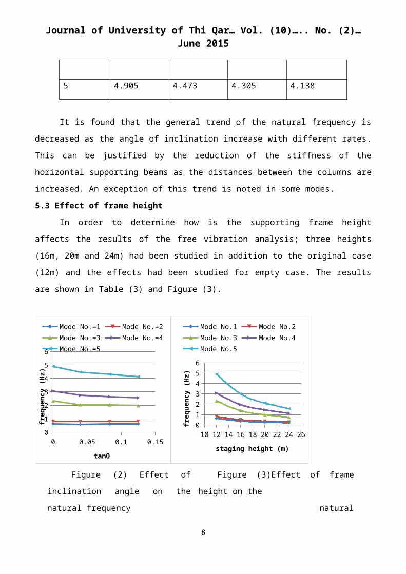
It is found that the general trend of the natural frequency is decreased as the angle of
inclination increase with different rates. This can be justified by the reduction of the stiffness of the
horizontal supporting beams as the distances between the columns are increased. An exception of this
trend is noted in some modes.
5.3 Effect of frame height
In order to determine how is the supporting frame height affects the results of the free
vibration analysis; three heights (16m, 20m and 24m) had been studied in addition to the original case
(12m) and the effects had been studied for empty case. The results are shown in Table (3) and Figure
(3).
5

Journal of University of Thi Qar… Vol. (10)….. No. (2)… June 2015
0 0.02 0.04 0.06 0.08 0.1 0.12 0.140
1
2
3
4
5
6
Mode No.=1 Mode No.=2Mode No.=3 Mode No.=4Mode No.=5
tanθ
freq
uenc
y (H
z)
10 12 14 16 18 20 22 24 260
1
2
3
4
5
6
Mode No.1 Mode No.2Mode No.3 Mode No.4Mode No.5
staging height (m)fr
eque
ncy
(Hz)
Figure (2) Effect of inclination angle on
the natural frequency
Figure (3)Effect of frame height on the
natural frequency
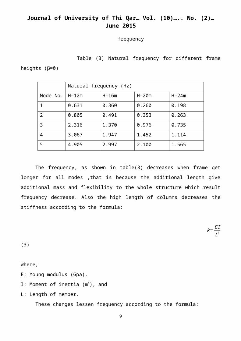
Table (3) Natural frequency for different frame heights (β=0)
The
frequency, as shown in table(3) decreases when frame get longer for all modes ,that is because the
additional length give additional mass and flexibility to the whole structure which result frequency
decrease. Also the high length of columns decreases the stiffness according to the formula:
k=EIL3 (3)
Where,
E: Young modulus (Gpa).
6
Mode No.
Natural frequency (Hz)
H=12m H=16m H=20m H=24m
1 0.631 0.360 0.260 0.198
2 0.805 0.491 0.353 0.263
3 2.316 1.370 0.976 0.735
4 3.067 1.947 1.452 1.114
5 4.905 2.997 2.100 1.565

Journal of University of Thi Qar… Vol. (10)….. No. (2)… June 2015
I: Moment of inertia (m4), and
L: Length of member.
These changes lessen frequency according to the formula:
f = 12 π √ k
m (4)
Where,
f : The natural frequency of the system (Hz).
k : is the stiffness.
m : structural mass (kg).
5.4 Earthquake Ground motion
Three cases including filled, half filled, and empty container are considered to assess the
dynamic response of the elevated tank. Response spectrum analysis has been done to conduct this
work. The tank is subjected to kocaeli earthquake, Turkey, 1999 with magnitude (Mw=7.4) on Richter
scale which has strong pulses nearly for 10 seconds.
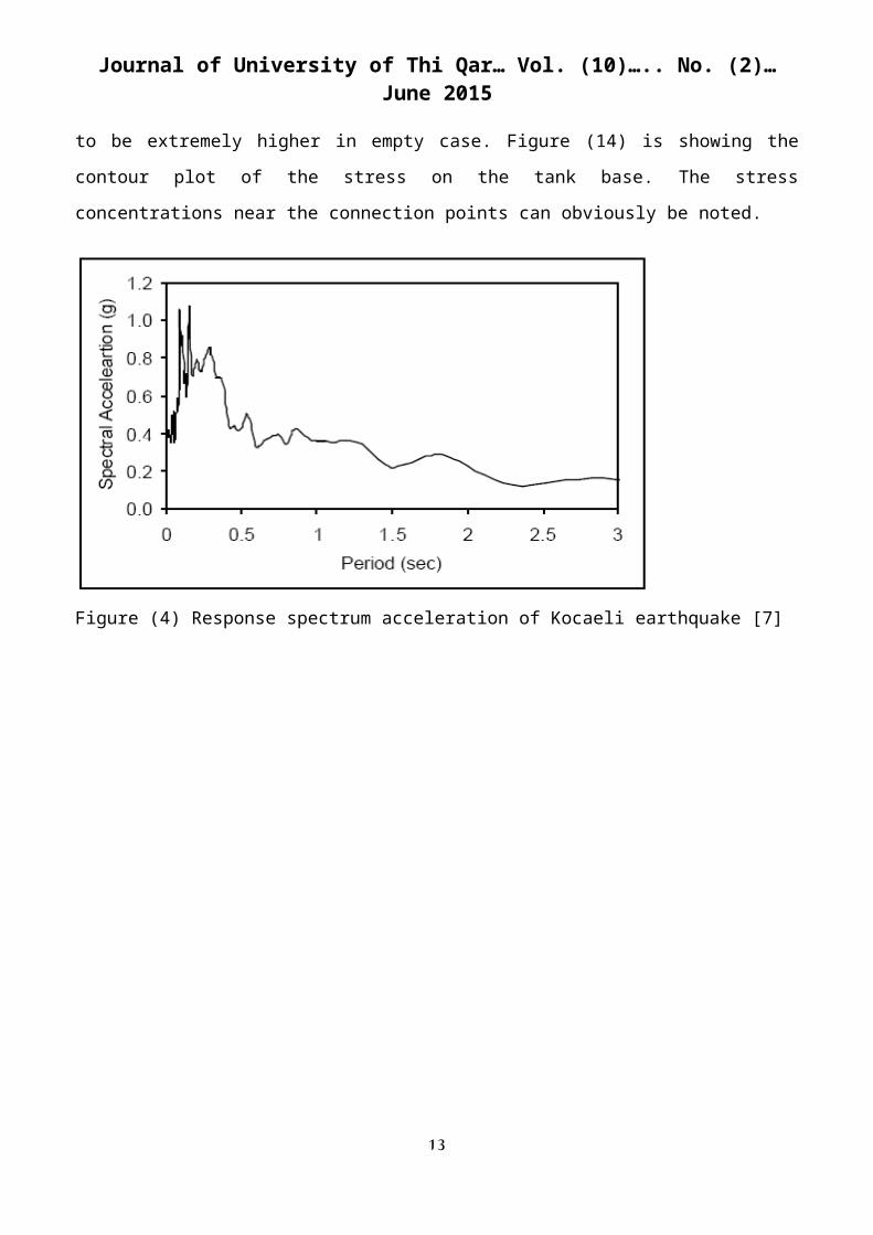
The frequency content of the motions can also be compared; in acceleration response spectra
Kocaeli Earthquake has its peak values in 0.2-0.3 seconds [7].
The horizontal components of Kocaeli earthquake acceleration are presented in Figure (4).
5.4.1 Shear force
It is clear from figure (5) that the values are approximately equal for all cases of filling in the
nodes selected with low difference among them. Also, shear force values varies from positive at one
level to negative at the next level, till to the end of frame height. At the end of frame and along the
height of tank, shear values are almost small and convergent.
5.4.2 Bending moment
The bending moment had begun with a very small negative value in the frame supporting point
and then it reflected between negative and positive values for the three cases of filling. It arrives it's
maximum values at the ends of every story height. The values of the three cases are approximately the
same with in the frame limits, a remarkable difference is happening in the beginning of tank height in
case of full container due to the large mass added to the tank while, for the other cases the base
moment values still near zero until the end of tank height. Figure (6) explains these variations of
bending moment with the tank height. The value of the overturning moment about the x-axis which is
7
Journal of University of Thi Qar… Vol. (10)….. No. (2)… June 2015
obtained from the element force of the column multiplied by the distance between columns is equal to
2.599, 2.606 and 2.612 kN.m for empty, half and full filling cases, respectively.
5.4.3 Lateral displacement
The values of displacement in the direction of earthquake (x-axis) have their peaks near the
mid height of the supporting structure for the three filling cases in different rates due to the column
bending, buckling and torsion occur in the frame as shown in figure (7). This makes the mid height
location is the most critical among other points of structure. The lateral displacement in this location is
found to be maximum for the case of half full tank and equal to (0.9983m), while the minimum value
of displacement occurs in the empty case and it is equal to (0.112m). The displacements, as noticed,
are so large that the elevated tank can lose stability even though the internal forces are small.
At the points above the mid height the displacement begins to decrease and then changes it's
direction to the opposite one at the top of frame. Along the height of the tank wall the displacement is
comparatively small and convergent, maximum displacement are noticed in case of full tank having a
value of (-0.26387m).
The relation between the filling ratio and the maximum displacement is shown in figure (8).
The figure shows that maximum displacement occurs in case of half full container. This can be
justified due to the coincidence between the frequency content of the earthquake and the natural
frequencies of the tank when it is half filled. Figures (11), (12) and (13) show the contour plots for the
displacement in case of full, half and empty vessel.
5.4.4 Shear stress
The critical points of the tank structure which suffer from maximum stresses are the points in
the region around the points of connection with the supporting frame as shown in figure (9). These
points are critical due to the large mass supported by four columns and the impulsive action in cases
of water presence inside the container. Figure (10) explains the variation in the values of stress in the
container only, including the bottom ring with the height along a vertical line located opposite to the
direction of earthquake; the stress varies from maximum negative value in the bottom of ring to a
specific positive value in the top of ring (0.6m), then the curve returns to a low negative value in a
height of (1.3m) and remain constant in the rest heights. Stress is found to be extremely higher in
empty case. Figure (14) is showing the contour plot of the stress on the tank base. The stress
concentrations near the connection points can obviously be noted.
8
Journal of University of Thi Qar… Vol. (10)….. No. (2)… June 2015
Figure (4) Response spectrum acceleration of Kocaeli earthquake [7]
-6 -4 -2 0 2 4 6 80
2
4
6
8
10
12
14
16
18empty-case Half-fullfull-case
shear force (kN)
Nod
e el
evati
on (m
)
Figure (5) X-component of base shear along Figure (6) X-component of moment along
the tank height for various full cases the tank height for various full cases
9
-0.2 -0.15 -0.1 -0.05 0 0.05 0.1 0.150
2
4
6
8
10
12
14
16
18Empty case full-casehalf-full
Bending moment (KN.M)
Nod
e el
evati
on (m
)
Journal of University of Thi Qar… Vol. (10)….. No. (2)… June 2015
0 0.1 0.2 0.3 0.4 0.5 0.6 0.7 0.8 0.9 10
0.2
0.4
0.6
0.8
1
1.2
1.4
1.6
filling percentageLa
tera
l disp
lace
men
t
Figure (7) Displacement in x-direction Figure
(8) Maximum (displacement-
for three full cases filling degree) variation
-4000000 -2000000 0 2000000
0
0.5
1
1.5
2
2.5
3
3.5
4Empty Half full Full
stress (N/m2)
Nod
e he
ight
(m)
Figure (9) Stress distribution on the empty Figure (10) x-component of stress for the
tank using ANSYS 11 software container body height
10
-0.4 -0.2 0 0.2 0.4 0.6 0.8 1 1.20
2
4
6
8
10
12
14
16
18Empty case full-casehalf-full
Node elevation (m)
Disp
lace
men
t (m
)
Journal of University of Thi Qar… Vol. (10)….. No. (2)… June 2015
Figure (11) Contour plot of displacement Figure (12) Contour plot of displacement
in x-direction for full case in x-direction for half full case
11
Journal of University of Thi Qar… Vol. (10)….. No. (2)… June 2015
Figure (13) Contour plot of displacement Figure (14) Stress distribution around the
in x-direction for empty tank base plate of the container
6. Conclusion
The main conclusions that can be obtained from the study are:
The critical response of elevated tanks may occur in full or half full condition. This depends on
the coincidence of the natural frequency and the earthquake characteristics in reduction or
amplification of system responses.
The maximum stress occurs in the points of connection between frame and container's body
which subject to high loading due to the big mass of the container connected to the slender
frame that these points suffer from.
Natural frequency decreases as frame height increases, when frame height is doubled the
natural frequency increment is found to be equal (68%).
Frame inclination increment lead to frequency decrement because: stiffness of columns and
beams decrease and their masses increase that give reverse effect on the natural frequency
values.
The lateral displacement in the x-direction due to earthquake has it's maximum value near the
middle of frame height because of the column-buckling.
ACKNOWLEDGMENTS
Praise and thanks to Allah who Reconciles me to complete this study. I would like to express my
thanks and regard to my supervisor, Dr. Abdulamir A. Karim for his time and help during all stages of
12
Journal of University of Thi Qar… Vol. (10)….. No. (2)… June 2015
this work I also thank Dr. (Mohammed Jawad K. Essa), head of civil engineering department. Also
thanks to Dr. (Rabee'a Hashim Thjeel), dean of college of engineering.
7. References
1. Ghandhi M.N. & Rajan A. "Necessity of Dynamic Analysis of Elevated Water Storage
Structure Using Different Bracing in Staging", international Journal of research in advent
Technology, Vol.2, No.2, February, 2014.
2. Omidinasab F. & Shakib H. "Seismic vulnerability of elevated water tanks using performance
based- design", the 14th world conference on earthquake engineering, October, 12-17, 2008,
Beijing, China.
3. Soroushnia S., Tafreshi Sh. T., Omidinasab F., Beheshtian N. & Sajad Soroushnia "Seismic
Performance of RC Elevated water Tanks with frame staging and Exhibition Damage Pattern",
The Twelfth East Asia Pacific conference on structural engineering and construction,2011.
4. Patel C. N., Kanjetawala B. &Patel H.S. "Influence of frame type tapered staging on sloshing
behavior of elevated water tank ", International Journal of advanced Engineering research and
studies, Dec., 2012.
5. Hirde S., Bajar. A. & Hedaoo M. "Seismic Performance of Elevated water tanks",
International Journal of Advanced engineering research and studies, vol.I/Issue I/ October-
December, 2011.
6. ANSYS 11.0 Inc.," Ansys user's manual", version11.0, USA, 2013.
7. Soyoz S. "Effect of soil structure Interaction and Base Isolated System on seismic performance
of foundation soils", Master Thesis, July, 2004.
13