v-i characteristics of scr - · pdf fileagmrcet dept of e&c v-i characteristics of scr...
TRANSCRIPT

AGMRCET DEPT OF E&C
V-I CHARACTERISTICS OF SCR
AIM:
To obtain V-I characteristics and to find on-state forward resistance of given SCR.
To determine holding, latching current and break over voltage of given SCR.
APPARATUS REQUIRED: Trainer kit, Patch cards, Multimeters.
CIRCUIT DIAGRAM:
Fig 1.1(a) Circuit diagram for VI characteristics of SCR.
VBO = Forward break over voltage
VBR = Reverse break over voltage
Ig = Gate current
Characteristic curve:
Fig 1.2(a) Static characteristic of SCR.
VBR
VBO
IAK
IG=I
G1
VAK

AGMRCET DEPT OF E&C
TABULAR COLUMN:
Gate current IG = IG1 =…..mA
VAK (Volts) IA (mA)
PROCEDURE:
Connections are made as shown in the circuit diagram.
Set R1 and R2 to mid position and V1 and V2 to minimum
Set the gate current IG = IG1 (such that forward break over voltage is between 15 to 20
V), by varying R2 and V2.
Slowly vary V1 in steps of 2V and note down VAK and IAk at each step till SCR
conducts. (Note down maximum VAK, which is forward break over voltage just before
SCR conducts).
FINDING LATCHING CURRENT:
Ensure that the SCR is in the state of conduction.
Start reducing (VAK) anode voltage in steps of 2V; simultaneously check the state of
SCR by switching off gate supply V2. If SCR switches off just by removing gate
terminal, and switches on by connecting gate supply, then the corresponding anode
current IA is the latching current (IL) for the SCR.
FINDING HOLDING CURRENT:
Ensure that the SCR is in the state of conduction.
Switch off the gate supply permanently.
Start reducing (VAK) anode voltage in steps of 2V; simultaneously check the state of
SCR. If SCR switches off. Note down the anode current (IA) just before it drops to
zero, which will be IH.
Reverse the anode voltage polarity.
Vary VAK in steps of 5V till 25V and note down VAK and IA values at each step
Plot forward and reverse characteristics using the above-tabulated values. Find the
SCR forward resistance using the graph.
Repeat the above procedure for the forward and reverse characteristics of SCR for a
gate current Ig = Ig2.
RESULT: The values of VAK and IAK are noted down, plotted and SCR forward
resistance is found. The values obtained are verified.

AGMRCET DEPT OF E&C
CHARACTERISTICS OF MOSFET
AIM: To draw static characteristic of MOSFET and hence to determine the output resistance and Trans conductance. APPARATUS REQUIRED: MOSFET module, Multimeters, patch chords. CIRCUIT DIAGRAM:
1 Connect the circuit as shown in the fig 2.1 (a). 2. Set VDS = 10V by varying V1. Keep R1 slightly more than ¼ of the total value. 3. Vary VGS by varying V2 (keep R2 to minimum position) and note down IDS for every 0.5V variation of VGS till 5V of VGS. 4. Min VGS voltage that is required for conduction is “Threshold voltage” (VTH). 5. Repeat the above experiment for different values of VDS2 = 15V.
2.5V-
45V
1.5V-
15V
AGMRCET DEPT OF E&C
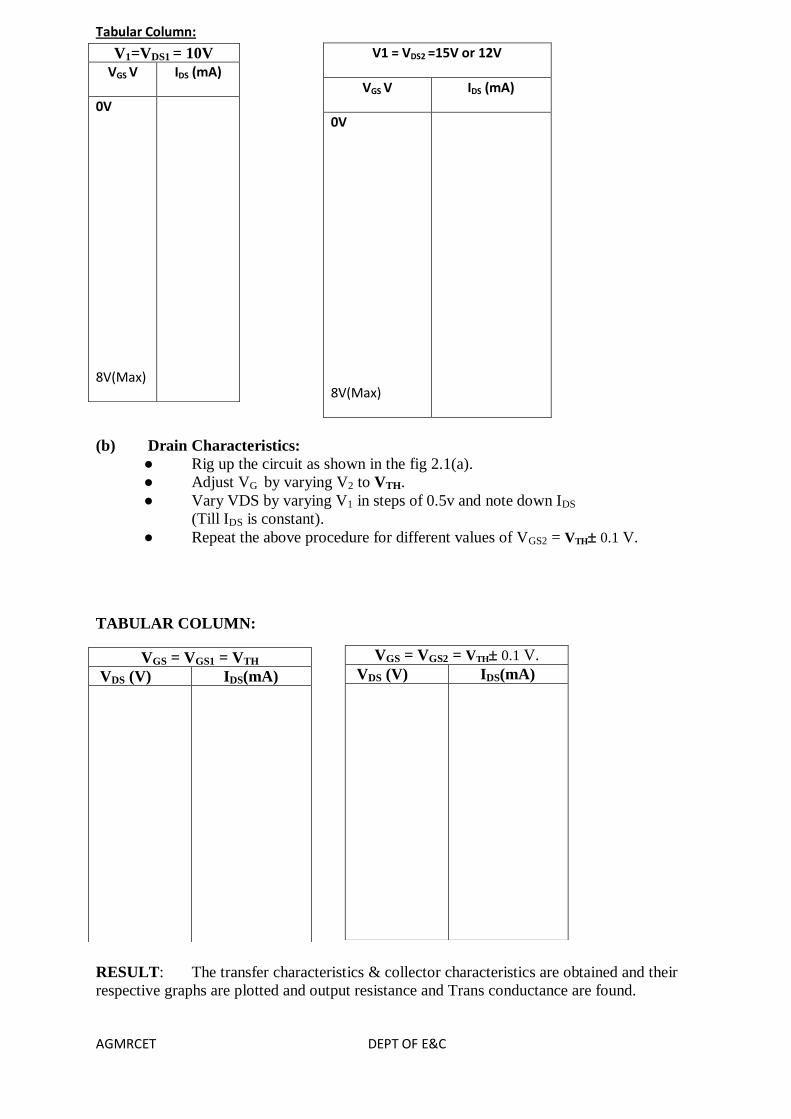
Tabular Column:
V1 = VDS2 =15V or 12V
VGS V IDS (mA)
0V
8V(Max)
(b) Drain Characteristics:
● Rig up the circuit as shown in the fig 2.1(a).
● Adjust VG by varying V2 to VTH.
● Vary VDS by varying V1 in steps of 0.5v and note down IDS
(Till IDS is constant).
● Repeat the above procedure for different values of VGS2 = VTH 0.1 V.
TABULAR COLUMN:
RESULT: The transfer characteristics & collector characteristics are obtained and their
respective graphs are plotted and output resistance and Trans conductance are found.
V1=VDS1 = 10V
VGS V IDS (mA)
0V
8V(Max)
VGS = VGS2 = VTH 0.1 V.
VDS (V) IDS(mA)
VGS = VGS1 = VTH
VDS (V) IDS(mA)
AGMRCET DEPT OF E&C
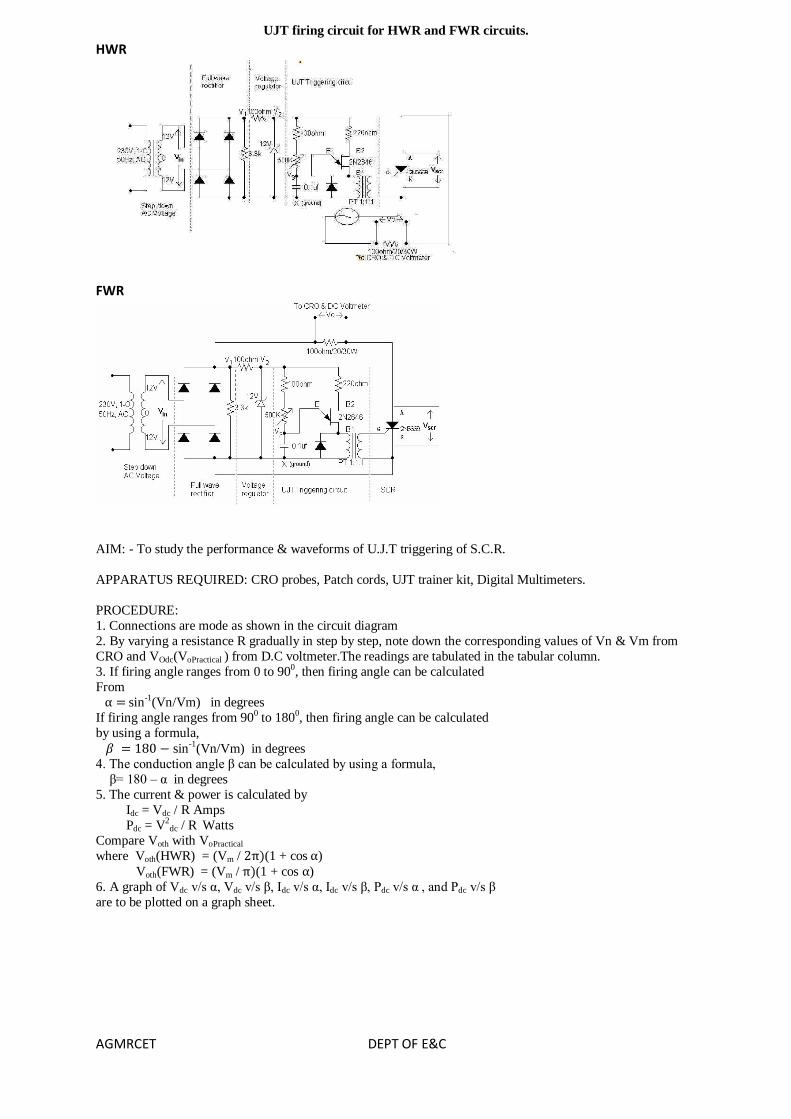
UJT firing circuit for HWR and FWR circuits.
HWR
FWR
AIM: - To study the performance & waveforms of U.J.T triggering of S.C.R.
APPARATUS REQUIRED: CRO probes, Patch cords, UJT trainer kit, Digital Multimeters.
PROCEDURE:
1. Connections are mode as shown in the circuit diagram
2. By varying a resistance R gradually in step by step, note down the corresponding values of Vn & Vm from
CRO and VOdc(VoPractical ) from D.C voltmeter.The readings are tabulated in the tabular column.
3. If firing angle ranges from 0 to 900, then firing angle can be calculated
From
sin-1(Vn/Vm) in degrees
If firing angle ranges from 900 to 1800, then firing angle can be calculated
by using a formula,
sin-1
(Vn/Vm) in degrees
4. The conduction angle β can be calculated by using a formula,
β= 180 – α in degrees
5. The current & power is calculated by
Idc = Vdc / R Amps
Pdc = V2dc / R Watts
Compare Voth with VoPractical
where Voth(HWR) = (Vm / (1 + cos )
Voth(FWR) = (Vm / (1 + cos )
6. A graph of Vdc v/s α, Vdc v/s β, Idc v/s α, Idc v/s β, Pdc v/s α , and Pdc v/s β
are to be plotted on a graph sheet.

AGMRCET DEPT OF E&C
IDEAL WAVEFORMS
TABULAR COLUMN
Draw the table HWR & FWR Wave form
VIVA QUESTIONS: -
1. Explain the working operation of U.J.T. triggering circuit waveforms? 2. Why U.J.T. Triggering circuit is superior when compared to R & RC triggering circuit?
3. What is the use of pulse transformer?
4. Explain the design part of UJT?
5. Write equivalent circuit of UJT and show that Vpeak = Vemitter = Vγ+ηVBB.
6. Why do we require turn-on circuits for thyristors?
7. Why do we require turn-off circuits for thyristors?
8. Comment on Forced & Natural Commutation techniques.

AGMRCET DEPT OF E&C
AC Voltage Control by using TRIAC-DIAC Combination
AIM: - To study the AC voltage control by using TRIAC-DIAC combination
APPARATUS REQUIRED: Patch cords, Multimeters, Isolation Transformer, 10:1 probes, lamp, Triac Module.
PROCEDURE: -
A.
1. Connections are mode as shown in the circuit diagram
2. By varying the variable resistance R1 in step by step, observe the variation of intensity of light.
B. 1. Connections are mode as shown in the circuit diagram
2. By varying the resistance R, in step-by-step note down the corresponding vales of Vn & Vm from C.R.O. and
Va.c(VoPractical ) from A.C. voltmeter the readings are tabulated in the tabular column
3. If firing angle ranges from 0 to 900, then firing angle can be calculated
From sin-1(Vn/Vm) in degrees
If firing angle ranges from 900 to 1800, then firing angle can be calculated
by using a formula, sin-1(Vn/Vm) in degrees
4. The conduction angle β can be calculated by using a formula,
β= 180 – α in degrees
5. The current & power is calculated by Idc = Vdc / R Amps
Pdc = V2dc / R Watts
Compare Voth with VoPractical where Voth= Vinrms
6. A graph of Iac v/s α, Vac or load voltage v/s α are to be plotted are to be plotted on a graph sheet.

AGMRCET DEPT OF E&C
IDEAL WAVEFORMS
TABULAR COLUMN
VIVA QUESTIONS: -
1. Explain the features of TRIAC?
2. Explain the working operation of illumination control & various voltage
output waveforms by using TRIAC? 3. Compare S.C.R, DIAC & TRIAC?
4. What is universal motor?
5. Comment on the different graphs of this experiment?
6. Mention the applications of TRIAC?

AGMRCET DEPT OF E&C
Single Phase Full Wave Controlled Rectifier
AIM: -
1. To study the performance and waveforms of full wave controlled rectifier with Resistance load and Inductive load
2. Plot a graph of VO v/s for R-load
APPARATUS REQUIRED:Trainer module, Multimeters, CRO ,Patch cords Rheostat, inductor.
PROCEDURE:
1. Connections are mode as shown in the circuit diagram
2. By varying a resistance R gradually in step by step, note down the
corresponding values of Vn & Vm from CRO and VOdc(VoPractical ) from D.C voltmeter.
The readings are tabulated in the tabular column.
3. If firing angle ranges from 0 to 900, then firing angle can be calculated
From
sin-1(Vn/Vm) in degrees If firing angle ranges from 900 to 1800, then firing angle can be calculated
by using a formula,
sin-1(Vn/Vm) in degrees
4. The conduction angle β can be calculated by using a formula,
β= 180 – α in degrees
5. The current & power is calculated by
Idc = Vdc / R Amps
Pdc = V2dc / R Watts
Compare Voth with VoPractical where Voth= (Vm / (1 + cos )
6. A graph of Vdc v/s α, Vdc v/s β, Idc v/s α, Idc v/s β, Pdc v/s α , and Pdc v/s β are to be plotted on a graph sheet.
7. Plot a graph of VDC or Vload or VO v/s firing angle α ,with R load, R-L load without freewheeling diode, R
L with Free wheeling diode.
Graph
Expected Wave forms:
Output wave form with R load

AGMRCET DEPT OF E&C
Output waveforms across R-L load without freewheeling diode
Output waveforms across R-L load with freewheeling diode.
TABULAR COLUMN
Draw the table for Output wave form with R load, Output waveforms across R-L load without freewheeling
diode, R L with Free wheeling diode.
VIVA QUESTIONS: -
1. Explain the performance and working operation of single-phase full controlled rectifier with relevant
waveforms for Resistive load, Inductive load.
2. Compare H.C.R with F.C.R
3. In cyclo-converter, why H.C.R with Inductive load cannot be implemented

AGMRCET DEPT OF E&C
AUXILLARY COMMUTATION MODULE
Aim- To study SCR turn off using Auxiliary Commutation
APPARATUS REQUIRED: CRO probes, Patch cords, trainer kit, Digital Multimeters.
Procedure: -
1. Connections are made as shown in the circuit diagram.
2. Input DC voltage is set to convenient value (10v to 25v). 3. By varying duty cycle knob of triggering circuit module step by step gradually note down corresponding Ton
and T from the CRO and VO from DC voltmeter and tabulate.
4. Duty cycle ‘K’ is calculated by using K =Ton /T
5. A graph of VO v/s K is plotted.
6. Observe load and device voltage waveforms.
TABULAR COLUMN

AGMRCET DEPT OF E&C
Controlled HWR and FWR using RC triggering circuit
HWR
FWR
HWR & FWR Wave form
AIM: -
To study the performance & waveforms of HWR & FWR by using RC
triggering Circuit
APPARATUS REQUIRED: CRO probes, Patch cords, trainer kit, Digital Multimeters.
PROCEDURE:
1. Connections are mode as shown in the circuit diagram
2. By varying a resistance R gradually in step by step, note down the corresponding values of Vn & Vm from
CRO and VOdc(VoPractical ) from D.C voltmeter.The readings are tabulated in the tabular column.
3. If firing angle ranges from 0 to 900, then firing angle can be calculated
From
sin-1(Vn/Vm) in degrees
If firing angle ranges from 900 to 1800, then firing angle can be calculated
by using a formula,
sin-1(Vn/Vm) in degrees
4. The conduction angle β can be calculated by using a formula,
β= 180 – α in degrees
5. The current & power is calculated by

AGMRCET DEPT OF E&C
Idc = Vdc / R Amps
Pdc = V2dc / R Watts
Compare Voth with VoPractical
where Voth(HWR) = (Vm / (1 + cos )
Voth(FWR) = (Vm / (1 + cos ) 6. A graph of Vdc v/s α, Vdc v/s β, Idc v/s α, Idc v/s β, Pdc v/s α , and Pdc v/s β
are to be plotted on a graph sheet.
TABULAR COLUMN
Draw the table HWR & FWR Wave form

AGMRCET DEPT OF E&C
Series Inverter
Aim: -
To obtain variable AC from DC ripple input.
APPARATUS REQUIRED: CRO probes, Patch cords, trainer kit, Digital Multimeters.
Procedure: -
1. To begin with switch on the power supply to the firing circuit check that
trigger pulses by varying the frequency.
2. Connections are made as shown in the circuit diagram.
3. Now connect trigger outputs from the firing circuits to gate and cathode of
SCRs T1 & T2.
4. Connect DC input from a 30v/2A regulated power supply and switch on
the input DC supply.
5. Now apply trigger pulses to SCRs and observe voltage waveform across
the load.
6. Measure Vorms & frequency of o/p voltage waveform.
AGMRCET DEPT OF E&C
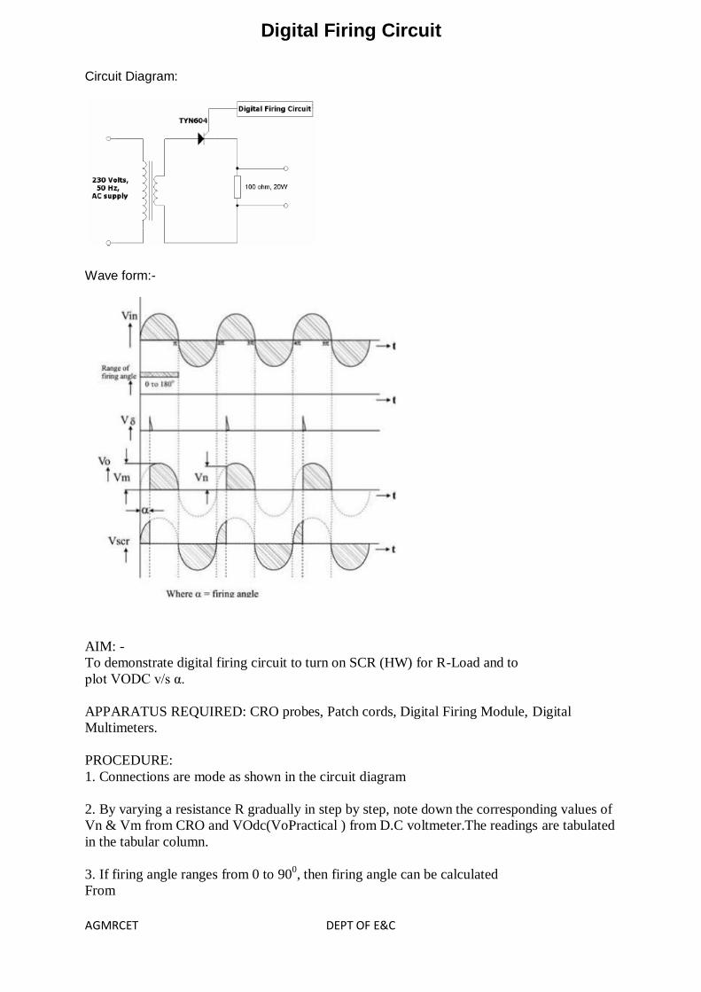
Digital Firing Circuit
Circuit Diagram:
Wave form:-
AIM: -
To demonstrate digital firing circuit to turn on SCR (HW) for R-Load and to
plot VODC v/s α.
APPARATUS REQUIRED: CRO probes, Patch cords, Digital Firing Module, Digital
Multimeters.
PROCEDURE:
1. Connections are mode as shown in the circuit diagram
2. By varying a resistance R gradually in step by step, note down the corresponding values of
Vn & Vm from CRO and VOdc(VoPractical ) from D.C voltmeter.The readings are tabulated
in the tabular column.
3. If firing angle ranges from 0 to 900, then firing angle can be calculated
From

AGMRCET DEPT OF E&C
sin-1(Vn/Vm) in degrees
If firing angle ranges from 900 to 180
0, then firing angle can be calculated
by using a formula,
sin-1(Vn/Vm) in degrees
4. The conduction angle β can be calculated by using a formula,
β= 180 – α in degrees
5. The current & power is calculated by
Idc = Vdc / R Amps
Pdc = V2dc / R Watts
Compare Voth with VoPractical
where Voth(HWR) = (Vm / (1 + cos )
6. A graph of Vdc v/s α are to be plotted on a graph sheet.
TABULAR COLUMN