v030454 sentry-rms configuration and installation manual€¦ · 2016-06-30...
TRANSCRIPT
2016-06-30
V030454_10_sentryRMS_Configuration_and_Installation_Manual.docx Page 1 of 110
V030454
Sentry-RMS Configuration and
Installation Manual
2016-06-30
V030454_10_sentryRMS_Configuration_and_Installation_Manual.docx Page 2 of 110
Table of Contents
Table of Contents ............................................................................................................................................................................... 2
List of Figures .................................................................................................................................................................................... 5 1 Overview ..............................................................................................................................................................................................8 2 Terminology .........................................................................................................................................................................................9
2.1 Acronyms ............................................................................................................................................................................. 10
2.2 Safety Symbols .................................................................................................................................................................... 10
3 Browser Requirements .......................................................................................................................................................................11 4 Hardware Installation Section ............................................................................................................................................................11
4.1 Sentry-RMS Wall Mounting ................................................................................................................................................ 12
Steps for Mounting the Sentry-RMS ....................................................................................................................... 16 4.1.1
4.2 Providing Power to the Sentry-RMS ................................................................................................................................... 17
Steps for providing power to the Sentry-RMS ........................................................................................................ 18 4.2.1
4.3 Network Ethernet Installation (hardware only) ................................................................................................................... 19 Steps for installing Ethernet cables .......................................................................................................................... 19 4.3.1
4.4 Mounting Additional Cameras ............................................................................................................................................. 22
Steps for Mounting Additional Cameras ................................................................................................................. 23 4.4.1
4.5 Camera Electrical Setup (as applicable) .............................................................................................................................. 26 Steps for the Electrical Setup of the Cameras to the Sentry-RMS (as applicable ................................................... 27 4.5.1
The following is the bandwith requirements for camera image quality: ................................................................. 29 4.5.2
4.6 Detaching Camera from Sentry-RMS chassis (as applicable) ............................................................................................. 30
Steps for removing an Sentry-RMS chassis camera: ............................................................................................... 30 4.6.1
4.7 Installing the Primary Backup Battery ................................................................................................................................. 35 4.8 Wiring the User-Provided Input and Output Devices to the Sentry-RMS........................................................................... 37
The Sentry-RMS has terminal strips (see Figure 26) for interfacing to TIDs, external alarm sensors, and external 4.8.1
alarm panels. ........................................................................................................................................................................ 37
Sentry-RMS Inputs .................................................................................................................................................. 38 4.8.2
Sentry-RMS Outputs to Alarm Panel ...................................................................................................................... 51 4.8.3
Plug in the primary backup cable into middle power jack, found at the bottom of the green, printed circuit board 4.8.4
(see Figure 36). .................................................................................................................................................................... 56
2016-06-30
V030454_10_sentryRMS_Configuration_and_Installation_Manual.docx Page 3 of 110
Apply AC power to the Sentry-RMS. ...................................................................................................................... 56 4.8.5
4.9 Tamper Sensors .................................................................................................................................................................... 57
Light Sensors ........................................................................................................................................................... 57 4.9.1
Back Plate Pressure Button ...................................................................................................................................... 57 4.9.2
5 Preparation for Software Setup of the Sentry-RMS Configuration Tool (SCT) ...............................................................................58
5.1 Option 1 - Connecting to the site via network ..................................................................................................................... 58 5.2 Using the Maintenance Port (Also Known as Camera Jack #3) .......................................................................................... 59
6 Sentry-RMS Configuration Tool – Login, Description and Usage ..................................................................................................60
6.1 Login to SCT and Event Viewer .......................................................................................................................................... 60 6.2 SCT Description and Usage ................................................................................................................................................. 62
7 Instructions on Setting Up the SCT ...................................................................................................................................................64 7.1 Configuration Tool Settings ................................................................................................................................................. 64
Update Firmware ..................................................................................................................................................... 65 7.1.1
Export Configurations .............................................................................................................................................. 66 7.1.2
Import Configurations .............................................................................................................................................. 67 7.1.3
Alarm/Alert Settings tab .......................................................................................................................................... 69 7.1.4
Monitoring Stations tab............................................................................................................................................ 75 7.1.5
Networking Tab - Ethernet, Set Passwords, State of Health, SMTP, SSL, Authentication Method ....................... 79 7.1.6
Cameras tab .............................................................................................................................................................. 86 7.1.7
Email/Text Notifications Tab .................................................................................................................................. 87 7.1.8
Data Storage tab ....................................................................................................................................................... 90 7.1.9
Configuration History tab ........................................................................................................................................ 91 7.1.10
Replacing the SCT configuration cable with the Primary Network cable ............................................................... 91 7.1.11
7.2 Event Viewer – Description and Usage ............................................................................................................................... 92 Logging in to Event Viewer ..................................................................................................................................... 92 7.2.1
State of Health.......................................................................................................................................................... 93 7.2.2
Alarms and Alerts tab .............................................................................................................................................. 94 7.2.3
Log tab ..................................................................................................................................................................... 96 7.2.4
7.3 Continue with Operator Interface Configuration Tool (OICT) Manual .............................................................................. 98
8 Technical Specifications ....................................................................................................................................................................99 8.1 Electrical Requirements ....................................................................................................................................................... 99 8.2 Water ingress protection rating ............................................................................................................................................ 99
2016-06-30
V030454_10_sentryRMS_Configuration_and_Installation_Manual.docx Page 4 of 110
8.3 Storage Temperature ............................................................................................................................................................ 99 8.4 Operating Temperature ........................................................................................................................................................ 99
8.5 Atmospheric Pressure (Altitude).......................................................................................................................................... 99 8.6 Humidity .............................................................................................................................................................................. 99
9 Maintenance & Servicing ..................................................................................................................................................................99
9.1 Radiation Detector Replacement Instructions ................................................................................................................... 100 Radiation Detector Removal .................................................................................................................................. 100 9.1.1
Radiation Detector Cover Installation ................................................................................................................... 104 9.1.2
9.2 Instructions for Cleaning.................................................................................................................................................... 108 9.3 Service and Repair ............................................................................................................................................................. 109
9.4 Contact Information ........................................................................................................................................................... 109 9.5 Warranty ............................................................................................................................................................................ 109
9.6 Replacement Battery .......................................................................................................................................................... 109 9.7 Replacement Fuses Specifications ..................................................................................................................................... 109 9.8 Sentry-RMS Open Ports .................................................................................................................................................... 110
9.9 Radiation Detection Procedure .......................................................................................................................................... 110
2016-06-30
V030454_10_sentryRMS_Configuration_and_Installation_Manual.docx Page 5 of 110
List of Figures
Figure 1 - Configuration Tool flow diagram .............................................................................................................................................. 8
Figure 2 - Sentry-RMS, mounting bracket, backup battery, cameras ....................................................................................................... 12 Figure 3 - Water-tight sealing washer and Nyloc nut ............................................................................................................................... 13
Figure 4 - Mounting Frame Dimensions ................................................................................................................................................... 14 Figure 5 - Right, lower mounting stud, water-tight washer and Nyloc nut .............................................................................................. 16 Figure 6 - Sentry-RMS terminal box ....................................................................................................................................................... 19
Figure 7 - Network Ethernet jacks ............................................................................................................................................................ 20 Figure 8 - Use Ethernet cable for Maintenance ........................................................................................................................................ 21 Figure 9 - Camera, camera base, and camera enclosure ........................................................................................................................... 22
Figure 10 - Camera mounting bracket with threaded base and cutaway for cord .................................................................................... 23 Figure 11 - Mounting bracket, camera base, camera enclosure, and camera ........................................................................................... 25
Figure 12 – Ethernet coupler ..................................................................................................................................................................... 26 Figure 13 - POE splitter (power cable and Ethernet jack) ........................................................................................................................ 26 Figure 14 - Camera connected to Ethernet cable and splitter ................................................................................................................... 27
Figure 15 - Ethernet camera jacks 1 – 4 ................................................................................................................................................... 28 Figure 16 - Camera power jacks ............................................................................................................................................................... 29
Figure 17 - Camera, Sentry-RMS chassis, and camera cord .................................................................................................................... 30 Figure 18 - Camera cable, Ethernet jacks and power jacks ...................................................................................................................... 31
Figure 19 - Removing camera from mounting bracket on Sentry-RMS chassis ...................................................................................... 32 Figure 20 - Removing camera mounting bracket ..................................................................................................................................... 33
Figure 21 - Placing water-tight gasket and camera plate on Sentry-RMS chassis ................................................................................... 34 Figure 22 - Attaching hex nuts on to camera plate studs .......................................................................................................................... 34 Figure 23 - Primary backup battery .......................................................................................................................................................... 35
Figure 24 - Battery in Sentry-RMS Chassis ............................................................................................................................................. 36 Figure 25 - Battery strapped into Sentry-RMS chassis ............................................................................................................................. 36
Figure 26 - Terminal blocks J1, J2, J6, J7, J8, and J14............................................................................................................................. 37
Figure 27 - Sentry-SEAL external TID Device ........................................................................................................................................ 39
Figure 28 - Example of Sentry-SEAL Configuration with Smart Interface ............................................................................................. 41 Figure 29 - Example of Sentry-SEAL Configuration with EOL Resistor Interface (Normally Open) – Seal must use Normally Open
configuration when used in EOLR configuration ..................................................................................................................................... 42 Figure 30 - Sentry-SEAL Wireless Receiver and Sentry-SEAL Wireless Transmitter ............................................................................ 43
2016-06-30
V030454_10_sentryRMS_Configuration_and_Installation_Manual.docx Page 6 of 110
Figure 31 - Example of Wireless Sentry-SEAL Receiver with Smart Interface ...................................................................................... 44 Figure 32 - Example of Wireless Sentry Seal Receiver with EOL Resistor Interface (Normally Open) – Seal must use Normally Open
configuration when used in EOLR configuration ..................................................................................................................................... 45 Figure 33 - Example of Wiring External Input Alarms (Normally Open) ............................................................................................... 46 Figure 34 – Wiring of Alarm Outputs....................................................................................................................................................... 52
Figure 35 – Example of Wiring Alarm Outputs ....................................................................................................................................... 53 Figure 36 - Backup battery power jack in the middle ............................................................................................................................... 56
Figure 37 - Back Plate Pressure Button .................................................................................................................................................... 57
Figure 38 – Primary and Secondary Ethernet jacks .................................................................................................................................. 59 Figure 39 - SCT opening screen ............................................................................................................................................................... 60
Figure 40 – System username credentials window ................................................................................................................................... 60 Figure 41 – System administrator credentials screen ............................................................................................................................... 61
Figure 42 - LDAP certificate prompt ........................................................................................................................................................ 61 Figure 43 - SCT initial setup screen ......................................................................................................................................................... 63 Figure 44 - Firmware update screen ......................................................................................................................................................... 65
Figure 45 - Exporting a configuration ...................................................................................................................................................... 66 Figure 46 - Importing a configuration ...................................................................................................................................................... 67
Figure 47 - Alarms and Alerts tab............................................................................................................................................................. 69 Figure 48 - Naming custom inputs............................................................................................................................................................ 70
Figure 49 - Naming custom output ........................................................................................................................................................... 71 Figure 50 - Mapping Alarm to outputs ..................................................................................................................................................... 72 Figure 51 - Naming TID, Sentry-SEAL, and Sentry-SEALWireless devices .......................................................................................... 73
Figure 52 - Naming radiation detector ...................................................................................................................................................... 74
Figure 53 - Battery level alarm/alert thresholds ....................................................................................................................................... 74 Figure 54 - Naming monitoring stations and generating Security Tokens ............................................................................................... 76 Figure 55 - Monitoring Station Setup ....................................................................................................................................................... 77 Figure 56 - Setting the number of stations required to acknowledge alarms............................................................................................ 78
Figure 57 - Entering primary and secondary Ethernet port information .................................................................................................. 79 Figure 58 - DHCP setup ............................................................................................................................................................................ 80
Figure 59 - State of Health settings and Sentry-RMS name ..................................................................................................................... 80 Figure 60 - Setting passwords ................................................................................................................................................................... 81 Figure 61 - Windows domain authentication for Sentry-RMS ................................................................................................................. 83
2016-06-30
V030454_10_sentryRMS_Configuration_and_Installation_Manual.docx Page 7 of 110
Figure 62 - SMTP setup ............................................................................................................................................................................ 84 Figure 63 - SSL setup ............................................................................................................................................................................... 85
Figure 64 - Naming and configuring cameras .......................................................................................................................................... 86 Figure 65 - Adding a user to receive test or email notifications ............................................................................................................... 87 Figure 66 - Text Message Address ........................................................................................................................................................... 88
Figure 67 - Configuring user notifications................................................................................................................................................ 89 Figure 68 - Data retention setup................................................................................................................................................................ 90
Figure 69 - Configuration history ............................................................................................................................................................. 91
Figure 70 - Opening screen SCT .............................................................................................................................................................. 92 Figure 71 - Event Viewer State of Health tab ........................................................................................................................................... 92
Figure 72 - Expanded view of State of Health .......................................................................................................................................... 93 Figure 73 - Alarms and Alerts tab............................................................................................................................................................. 94
Figure 74 - Download alarms and alerts history screen ............................................................................................................................ 94 Figure 75 - Alarms and alerts history ....................................................................................................................................................... 95 Figure 76 - Log, including events that are not alarms or alerts ................................................................................................................ 97
Figure 77 - Download all events from Log history................................................................................................................................... 98 Figure 78: Remove Screws and Washers............................................................................................................................................... 100
Figure 79: Disconnect Radiation Detector Harness ................................................................................................................................ 101 Figure 80: Remove Six Screws ............................................................................................................................................................... 102
Figure 81: Radiation Detector PCBA Removed ..................................................................................................................................... 103 Figure 82: Radiation Detector Installed onto Hot Plate .......................................................................................................................... 104 Figure 83: Radiation Detector Harness Connected to Radiation Detector ............................................................................................. 105
Figure 84. Radiation Detector Cover, Hardware, and Enclosure Lid Assembly .................................................................................... 106
Figure 85. Radiation Detector Cover Installed ....................................................................................................................................... 108
2016-06-30
V030454_10_sentryRMS_Configuration_and_Installation_Manual.docx Page 8 of 110
Sentry-RMS Configuration Manual
Setup Manual
1 Overview
The purpose of the Sentry Remote Monitoring System (Sentry-RMS) is to provide a security system focused on the protection of
radiological material by sending reliable transmission of alarms to responders at security monitors and by protecting against insider
threats. The Sentry-RMS measures gamma radiation dose rates from 100 mrem per hour to 1000 rem per hour.
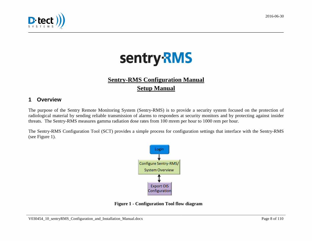
The Sentry-RMS Configuration Tool (SCT) provides a simple process for configuration settings that interface with the Sentry-RMS
(see Figure 1).
Figure 1 - Configuration Tool flow diagram
2016-06-30
V030454_10_sentryRMS_Configuration_and_Installation_Manual.docx Page 9 of 110
The Sentry-RMS Configuration Tool (SCT) is a web interface used to configure Sentry Remote Monitoring System (Sentry-RMS)
devices. The SCT configures the hardware of the Sentry-RMS, and associates the Sentry-RMS with one or more monitoring stations
(running the Operating Interface Software). NOTE: Another configuration tool is called the Operator Interface Configuration Tool
(OICT). The OICT is used to configure the monitoring stations associated with the Sentry-RMS. A complete Sentry-RMS
configuration procedure requires using both the SCT and the OICT. The SCT must be configured using this manual, then the user can
set up the OICT using the Operator Interface Configuration Tool Manual.
2 Terminology
• Alarm – An alarm is a serious event that indicates an attempt to access the Sentry-RMS enclosure or Asset source, or other critical
event. Alarms will only be associated with unauthorized access or scheduled maintenance. Alarm priorities vary. A high-radiation
alarm has the highest priority followed by a tamper-indicating device (TID) tamper alarm.
• Alert – Alerts indicate a fault event that prevents the Sentry-RMS from providing its intended protection. Alerts are usually
associated with a failure such as a loss of communications. Alerts can also be related to deliberate sabotage of the Sentry-RMS to aid
an attack on the asset.
• Asset – Any machine or device containing radioactive source material designated for protection by the Sentry-RMS
• Event – Any event that generates an alarm, alert, or Sentry-RMS system message regarding a change in status
• Relay, Normally Open - Relay is open in a non-alarming state.
• Relay, Normally Closed - Relay is closed (i.e. shorted) in a non-alarming state.
• Sentry-SEAL - A device designed to be attached to a secured surface adjacent to the protected object, or mounted inside a Sentry-
RMS case, or in a junction box. If an attempt is made to remove the entire protective enclosure, Sentry-SEAL will trigger an alarm.
• Sentry-SEAL Wireless - A system consisting of a Sentry-SEAL Wireless Receiver in wireless communication with a Sentry-SEAL
Wireless Transmitter. This wireless Receiver and Transmitter accomplishes the same purpose as the Sentry-SEAL, the difference
being that the Transmitter can be in one location, and the Receiver can be in another.
2016-06-30
V030454_10_sentryRMS_Configuration_and_Installation_Manual.docx Page 10 of 110
• Sentry-RMS – The “Sentry-RMS” may refer to the core Sentry-RMS hardware, or it may refer to the full Sentry-RMS architecture
from the TID sensors, to the user interface platform, and ancillary network communications that connect users to Sentry-RMS data.
• Site – The site refers to a location where Sentry-RMS units are installed. A site may encompass many buildings, such as a university
campus or hospital complex.
• Tamper Indicating Device – The TID is an actively-monitored seal or other sensor that detects tampering of the asset enclosure that
could lead to removal of the source.
• Operator Interface – The operator interface refers to the monitoring software that personnel have to receive, assess, and acknowledge
alarms.
2.1 Acronyms
SCT Sentry-RMS Configuration Tool
IP Internet Protocol
RMS Remote Monitoring System, an alternate designation for the Sentry-RMS
IT Information Technology
OICT Operator Interface Configuration Tool
OIS Operator Interface Software
SMS Short Message Service (cellular phone text messaging)
SoH State of Health
SSL Secure Socket Layer
TID Tamper Indicating Device
2.2 Safety Symbols
Potential Hazard Symbol: Documentation needs to be consulted in all cases where this symbol is used in order to determine
the nature of the potential hazard
2016-06-30
V030454_10_sentryRMS_Configuration_and_Installation_Manual.docx Page 11 of 110
3 Browser Requirements
The SCT will work with the following browsers: Google Chrome, Firefox, and Internet Explorer (version 9 and above). For Internet
Explorer 9, compatibility view should be disabled when view the webpage.
4 Hardware Installation Section
Before the Sentry-RMS can be configured in correlation with the SCT, the Sentry-RMS must be mounted to a wall and power
supplied to the unit by a qualified electrician. Then, the steps for the SCT software/firmware configuration should be completed.
Following the configuration, the rest of the hardware installation should be completed, including Ethernet hookup, terminal
connection of sensor inputs, and camera installation. It is crucial that a qualified person connect any user-provided Tamper
Identification Devices (TIDs), alarm panel outputs, or additional alarm inputs to the Sentry-RMS, as applicable.
It is recommended that two people mount the box to the wall, for the safety of the installers.
All of the above-mentioned steps are outlined in the following pages.
2016-06-30
V030454_10_sentryRMS_Configuration_and_Installation_Manual.docx Page 12 of 110
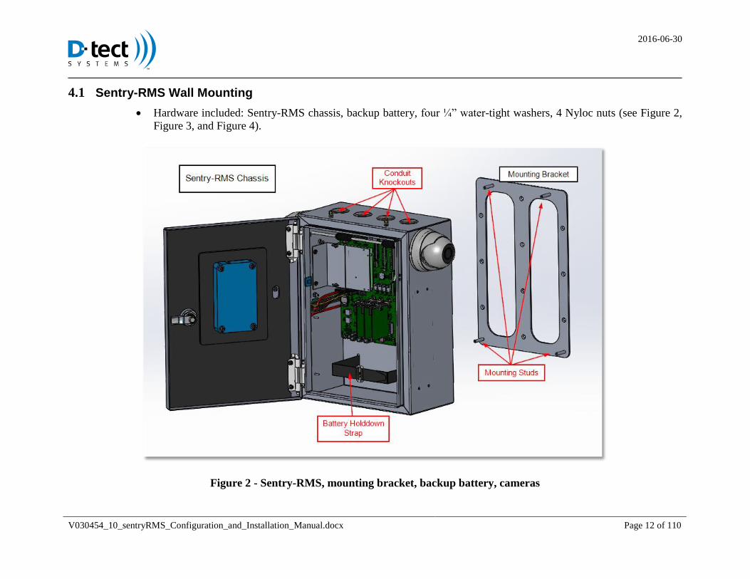
4.1 Sentry-RMS Wall Mounting
Hardware included: Sentry-RMS chassis, backup battery, four ¼” water-tight washers, 4 Nyloc nuts (see Figure 2,
Figure 3, and Figure 4).
Figure 2 - Sentry-RMS, mounting bracket, backup battery, cameras

2016-06-30
V030454_10_sentryRMS_Configuration_and_Installation_Manual.docx Page 13 of 110
Figure 3 - Water-tight sealing washer and Nyloc nut
2016-06-30
V030454_10_sentryRMS_Configuration_and_Installation_Manual.docx Page 14 of 110
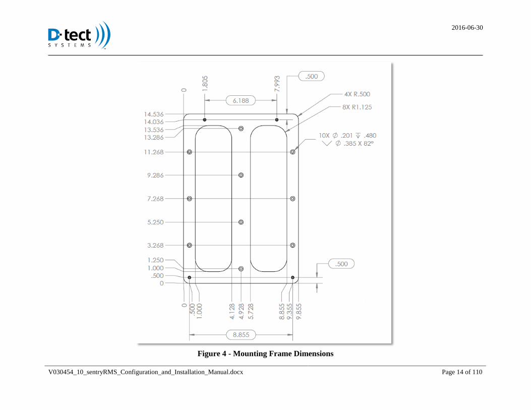
Figure 4 - Mounting Frame Dimensions
2016-06-30
V030454_10_sentryRMS_Configuration_and_Installation_Manual.docx Page 15 of 110
Tools needed: ratchet wrench with extension, 7/16” socket, medium flathead screwdriver, drill with bit and screw
driver (bit size appropriate for size of wall anchors)
User-supplied materials needed:
o Wall anchors (10 total - such as lag bolts and shields for concrete or block, metal anchors for drywall, etc)
sufficient in size and length and suitable for the wall construction to secure the Sentry-RMS to the wall and
support the weight of the Sentry-RMS, the backup battery, as well as the NEMA 4 conduit that will be
attached to the chassis of the Sentry-RMS (having a total weight of approximately 30 pounds)
o Flat-head, counter-sunk screws (10 total - #10 size) sufficient in length to work with the wall anchors, to
support the weight of the Sentry-RMS, and to fit flush in the holes that are pre-drilled in the mounting
bracket
The holes in the mounting brackets are .201″ in diameter, with an 82º counter-sink
2016-06-30
V030454_10_sentryRMS_Configuration_and_Installation_Manual.docx Page 16 of 110
Steps for Mounting the Sentry-RMS 4.1.1 Locate a stable place to mount the Sentry-RMS. If the device is being mounted on gypsum/sheetrock, or other fragile surface, 4.1.1.1
ensure that the Sentry-RMS will have the center of the mounting bracket placed directly over something such as a wood or
metal wall stud.
Mark where the 10 holes for the mounting bracket will be drilled, using the mounting bracket as a template. Be certain to line 4.1.1.2
up the middle of the bracket over a secure location such as a wood or metal wall stud. Properly and safely drill holes for the
wall anchors and then insert the wall anchors.
Place the mounting bracket over the holes and insert one flat-head, counter-sunk screw into each mounting hole. 4.1.1.3
Lift the Sentry-RMS up onto mounting bracket, aligning the 4 mounting studs with the holes in the chassis of the Sentry-4.1.1.4
RMS. For personal safety reasons, a second person should assist with this and the next three steps.
Place one of the provided, water-tight sealing washers on each mounting stud. 4.1.1.5
Place one of the provided Nyloc nuts on top of the washer on the mounting stud, and tighten the nut down with the 7/16” 4.1.1.6
socket wrench until secure.
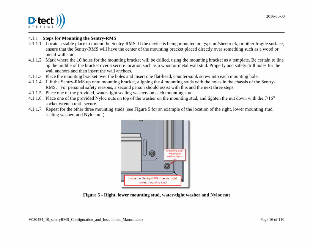
Repeat for the other three mounting studs (see Figure 5 for an example of the location of the right, lower mounting stud, 4.1.1.7
sealing washer, and Nyloc nut).
Figure 5 - Right, lower mounting stud, water-tight washer and Nyloc nut
2016-06-30
V030454_10_sentryRMS_Configuration_and_Installation_Manual.docx Page 17 of 110
4.2 Providing Power to the Sentry-RMS
Hardware included: Sentry-RMS terminal box and terminal screws (inside chassis of Sentry-RMS)
Tools needed: appropriate tools for connection of NEMA 4 conduit and wiring as required by the National Electric Code
(NEC) to deliver 120VAC power to the Sentry-RMS
User-provided supplies: EMT NEMA 4 conduit – ¾” (the length should be sufficient to reach from where the Sentry-
RMS will be installed to where it will meet the power supply provided by the facilities; allow for any curvature necessary
to reach the power supply and still meet highest electrical code); EMT rain-tight couplings – ¾″ (four couplings)
2016-06-30
V030454_10_sentryRMS_Configuration_and_Installation_Manual.docx Page 18 of 110
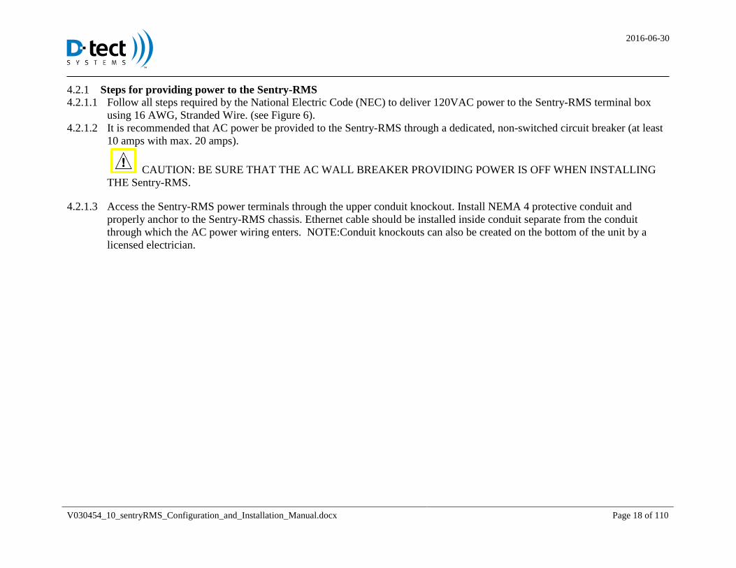
Steps for providing power to the Sentry-RMS 4.2.1 Follow all steps required by the National Electric Code (NEC) to deliver 120VAC power to the Sentry-RMS terminal box 4.2.1.1
using 16 AWG, Stranded Wire. (see Figure 6).
It is recommended that AC power be provided to the Sentry-RMS through a dedicated, non-switched circuit breaker (at least 4.2.1.2
10 amps with max. 20 amps).
CAUTION: BE SURE THAT THE AC WALL BREAKER PROVIDING POWER IS OFF WHEN INSTALLING
THE Sentry-RMS.
Access the Sentry-RMS power terminals through the upper conduit knockout. Install NEMA 4 protective conduit and 4.2.1.3
properly anchor to the Sentry-RMS chassis. Ethernet cable should be installed inside conduit separate from the conduit
through which the AC power wiring enters. NOTE:Conduit knockouts can also be created on the bottom of the unit by a
licensed electrician.
2016-06-30
V030454_10_sentryRMS_Configuration_and_Installation_Manual.docx Page 19 of 110
Figure 6 - Sentry-RMS terminal box
4.3 Network Ethernet Installation (hardware only)
Hardware included: N/A
Tools needed: N/A
User-provided supplies: Ethernet cable (the length should be sufficient to reach from where the Sentry-RMS will be
installed to where the cable will be plugged into the wall, router, or into a computer)
Steps for installing Ethernet cables 4.3.1
An Ethernet cable will be used in order to begin the setup of the Sentry-RMS Configuration Tool (SCT), and to access the 4.3.1.1
SCT web page. There are two options on how the user can proceed: Option 1 is to use DHCP on the primary Ethernet
2016-06-30
V030454_10_sentryRMS_Configuration_and_Installation_Manual.docx Page 20 of 110
Communications port, or Option 2 is to use a local connection by using a laptop plugged into the Maintenance Port. Choose
one of these options, and follow the steps listed.
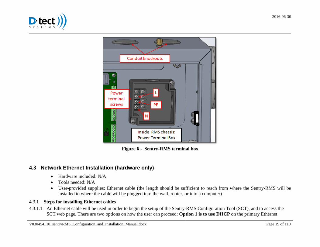
4.3.1.1.1 Option 1: If the user is going to use DHCP on the Primary Ethernet Communications port, do the following:
Take Ethernet cables and attach them to the following:
o Rear left jack: Primary Communications computer/network cable (see Figure 7).
Run the other end of the cable(s) up through the top of the Sentry-RMS (through a conduit knockout
hole) and insert the Primary Ethernet cable into the site network router or switch.
When beginning the software portion of setting up the Sentry-RMS (see Section 5 of this manual), assign a
fixed IP address for the Primary Communications port on the site DHCP server using the first MAC address
found on the sticker inside the Sentry-RMS box.
o If the user is going to have a Secondary Communications port, repeat this process for the Secondary
port (Rear middle jack) using the second MAC address (see Figure 7). The Secondary fixed IP
address must be on a separate subnet.
Figure 7 - Network Ethernet jacks
4.3.1.1.2 Option 2: If the user is going to use a local connection using a laptop plugged into the Maintenance Port, do
the following, when proceeding with the software setup of the Sentry-RMS (see Section 5 of this manual):
Ensure that the laptop is running with automatic or DHCP assigned addressing.
2016-06-30
V030454_10_sentryRMS_Configuration_and_Installation_Manual.docx Page 21 of 110
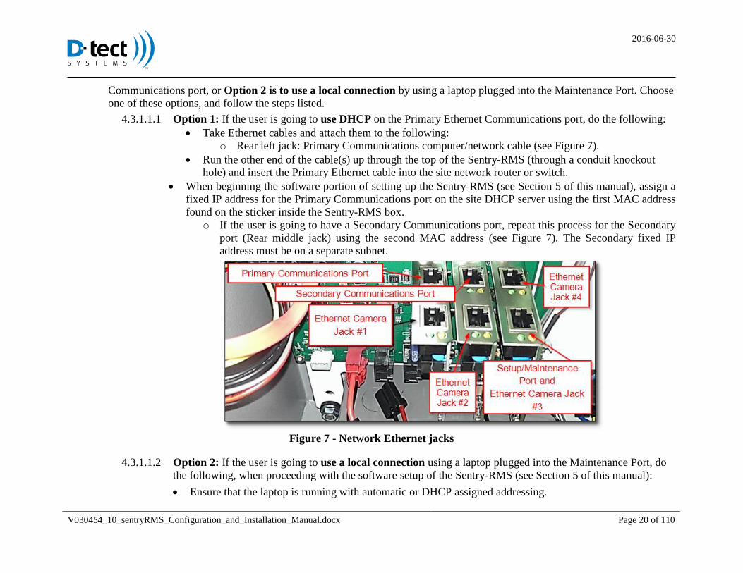
Connect the Ethernet cable into the Maintenance port, and then into the user’s laptop (see Figure 8).
o IMPORTANT: Do not use the POE splitter cable when connecting a laptop to the Maintenance
Port. This may damage the laptop’s Ethernet card. Instead, use a standard Ethernet cable between
the laptop going directly into the Sentry-RMS Maintenance Port (see Figure 8).
o NOTE: After software setup is complete (see section 7.1), the setup computer can be disconnected.
Figure 8 - Use Ethernet cable for Maintenance
2016-06-30
V030454_10_sentryRMS_Configuration_and_Installation_Manual.docx Page 22 of 110
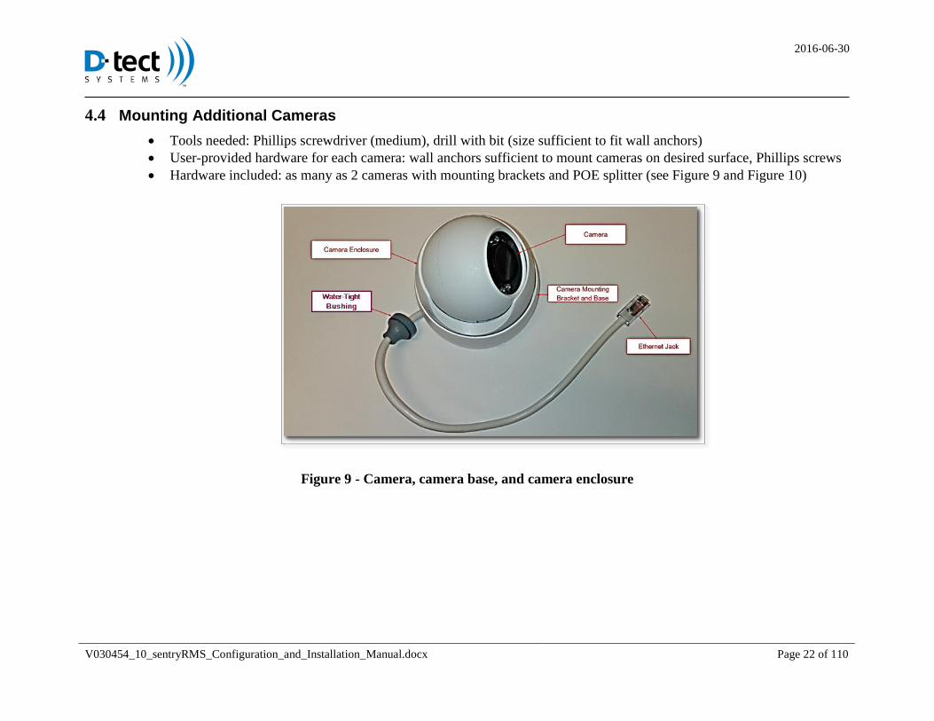
4.4 Mounting Additional Cameras
Tools needed: Phillips screwdriver (medium), drill with bit (size sufficient to fit wall anchors)
User-provided hardware for each camera: wall anchors sufficient to mount cameras on desired surface, Phillips screws
Hardware included: as many as 2 cameras with mounting brackets and POE splitter (see Figure 9 and Figure 10)
Figure 9 - Camera, camera base, and camera enclosure

2016-06-30
V030454_10_sentryRMS_Configuration_and_Installation_Manual.docx Page 23 of 110
Figure 10 - Camera mounting bracket with threaded base and cutaway for cord
Steps for Mounting Additional Cameras 4.4.1 Each Sentry-RMS will typically come with 2 pre-installed, chassis-mounted cameras. This manual will assume that the user 4.4.1.1
will be installing as many as 2 additional cameras, mounted throughout the room where the Sentry-RMS is installed. These
instructions will teach the user how to install 2 cameras, labeled cameras 3 and 4. This manual will also instruct the user how
to remove a camera from the chassis of the Sentry-RMS (as needed), and replace the camera with a water-tight gasket.
The mounting bracket and the base of the camera are threaded into each other (see previous Figure 10). Twist them in 4.4.1.2
opposite directions to unscrew the mounting bracket from the base. Take caution not to let the camera or camera enclosure
fall.
Mark the location of the placement of the camera mounting-bracket holes. 4.4.1.3
Drill holes and place wall anchors as required to support the weight of the camera, base, and required Ethernet cable. 4.4.1.4
Line up the holes of the mounting bracket with the holes in the wall. 4.4.1.5
NOTE: The camera cable must be placed under the mounting bracket prior to screwing the bracket in place. Be certain that
the cord is threaded through one of the cut-away sections on the bottom of the mounting bracket to keep the

2016-06-30
V030454_10_sentryRMS_Configuration_and_Installation_Manual.docx Page 24 of 110
cord from being pinched (see previous Figure 10). Be certain that the grey water-tight bushing is outside of the
mounting bracket.
Use Phillips screws (or other screws, as needed) to attach the mounting bracket to the flat surface. 4.4.1.6
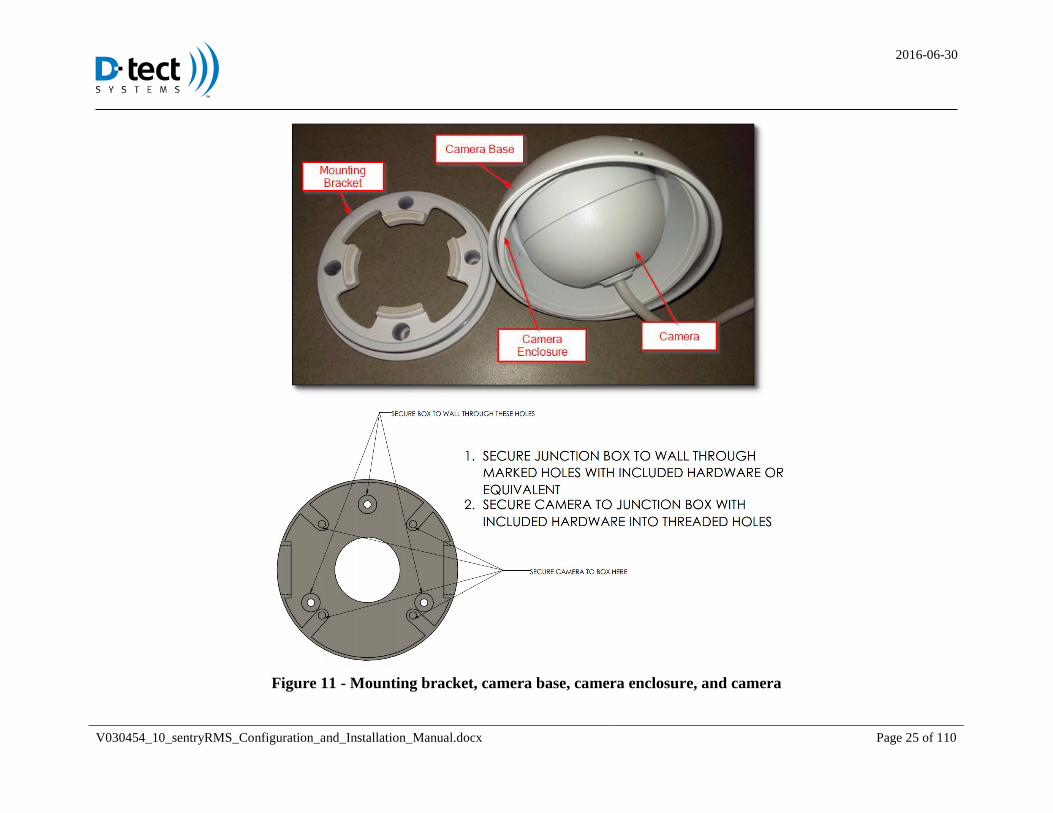
Re-attach the base of the camera, the camera enclosure, and the camera by twisting the base back onto the mounting bracket 4.4.1.7
(see Figure11).
2016-06-30
V030454_10_sentryRMS_Configuration_and_Installation_Manual.docx Page 25 of 110
Figure 11 - Mounting bracket, camera base, camera enclosure, and camera
2016-06-30
V030454_10_sentryRMS_Configuration_and_Installation_Manual.docx Page 26 of 110
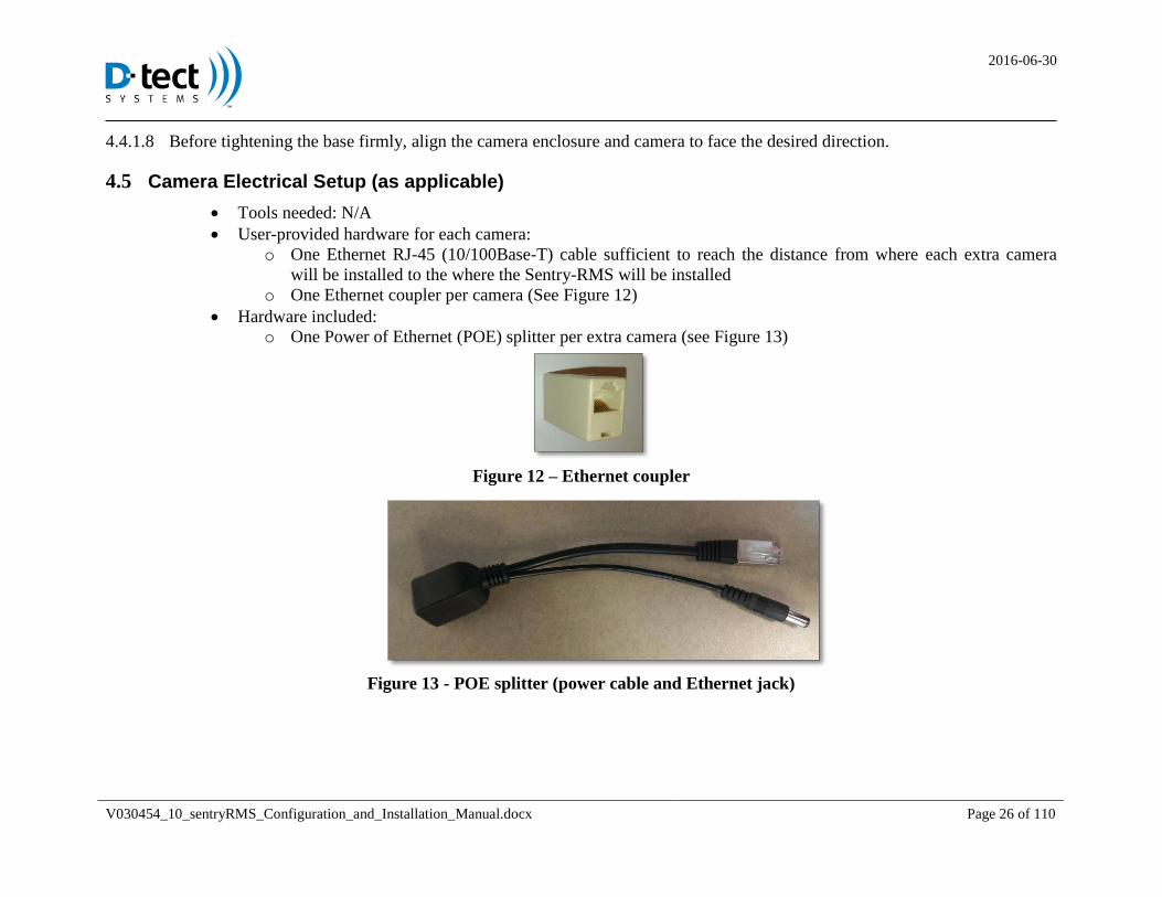
Before tightening the base firmly, align the camera enclosure and camera to face the desired direction. 4.4.1.8
4.5 Camera Electrical Setup (as applicable)
Tools needed: N/A
User-provided hardware for each camera:
o One Ethernet RJ-45 (10/100Base-T) cable sufficient to reach the distance from where each extra camera
will be installed to the where the Sentry-RMS will be installed
o One Ethernet coupler per camera (See Figure 12)
Hardware included:
o One Power of Ethernet (POE) splitter per extra camera (see Figure 13)
Figure 12 – Ethernet coupler
Figure 13 - POE splitter (power cable and Ethernet jack)

2016-06-30
V030454_10_sentryRMS_Configuration_and_Installation_Manual.docx Page 27 of 110
Steps for the Electrical Setup of the Cameras to the Sentry-RMS (as applicable 4.5.1
First: Connect the end of the camera Ethernet jack to the user-provided Ethernet Coupler. 4.5.1.1
Second: Connect the other end of the coupler to the user-provided Ethernet cable (one sufficiently long to reach the Sentry-4.5.1.2
RMS chassis from the mounted location).
Third: Connect the other end of the user-provided Ethernet cable to the provided POE Splitter. See Figure 14. 4.5.1.3
Figure 14 - Camera connected to Ethernet cable and splitter
2016-06-30
V030454_10_sentryRMS_Configuration_and_Installation_Manual.docx Page 28 of 110
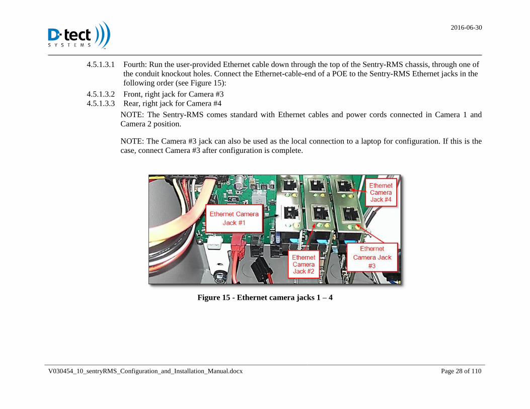
4.5.1.3.1 Fourth: Run the user-provided Ethernet cable down through the top of the Sentry-RMS chassis, through one of
the conduit knockout holes. Connect the Ethernet-cable-end of a POE to the Sentry-RMS Ethernet jacks in the
following order (see Figure 15):
4.5.1.3.2 Front, right jack for Camera #3
4.5.1.3.3 Rear, right jack for Camera #4
NOTE: The Sentry-RMS comes standard with Ethernet cables and power cords connected in Camera 1 and
Camera 2 position.
NOTE: The Camera #3 jack can also be used as the local connection to a laptop for configuration. If this is the
case, connect Camera #3 after configuration is complete.
Figure 15 - Ethernet camera jacks 1 – 4
2016-06-30
V030454_10_sentryRMS_Configuration_and_Installation_Manual.docx Page 29 of 110
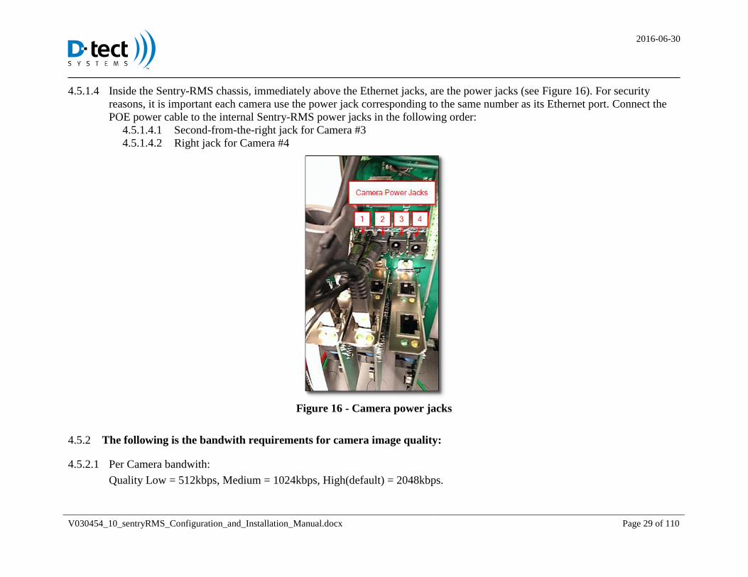
Inside the Sentry-RMS chassis, immediately above the Ethernet jacks, are the power jacks (see Figure 16). For security 4.5.1.4
reasons, it is important each camera use the power jack corresponding to the same number as its Ethernet port. Connect the
POE power cable to the internal Sentry-RMS power jacks in the following order:
4.5.1.4.1 Second-from-the-right jack for Camera #3
4.5.1.4.2 Right jack for Camera #4
Figure 16 - Camera power jacks
The following is the bandwith requirements for camera image quality: 4.5.2
Per Camera bandwith: 4.5.2.1
Quality Low = 512kbps, Medium = 1024kbps, High(default) = 2048kbps.
2016-06-30
V030454_10_sentryRMS_Configuration_and_Installation_Manual.docx Page 30 of 110
With 2 cameras: 4.5.2.2
Quality Low = 1024kbps, Medium = 4096kbps, High = 4096
4.6 Detaching Camera from Sentry-RMS chassis (as applicable)
Tools needed: adjustable crescent wrench, needle-nose pliers, Allen wrench 9/64”
Hardware provided: water-tight gasket, camera plate with four studs, four hex nuts
Steps for removing an Sentry-RMS chassis camera: 4.6.1
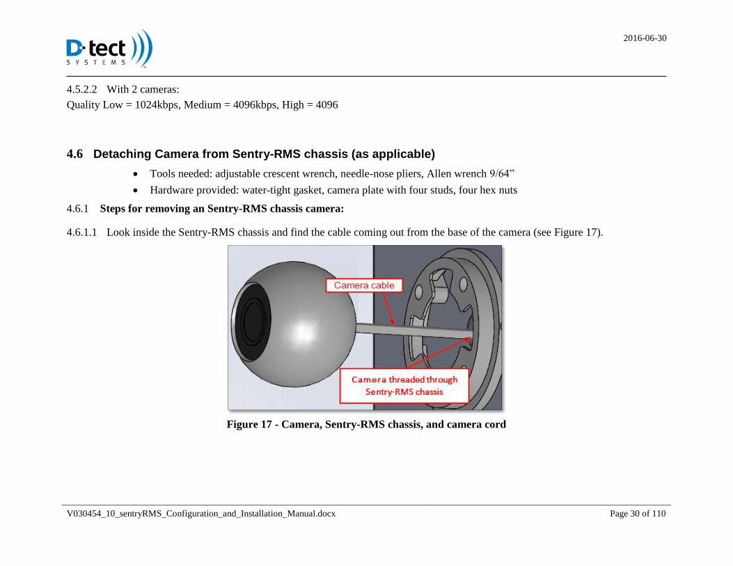
Look inside the Sentry-RMS chassis and find the cable coming out from the base of the camera (see Figure 17). 4.6.1.1
Figure 17 - Camera, Sentry-RMS chassis, and camera cord
2016-06-30
V030454_10_sentryRMS_Configuration_and_Installation_Manual.docx Page 31 of 110
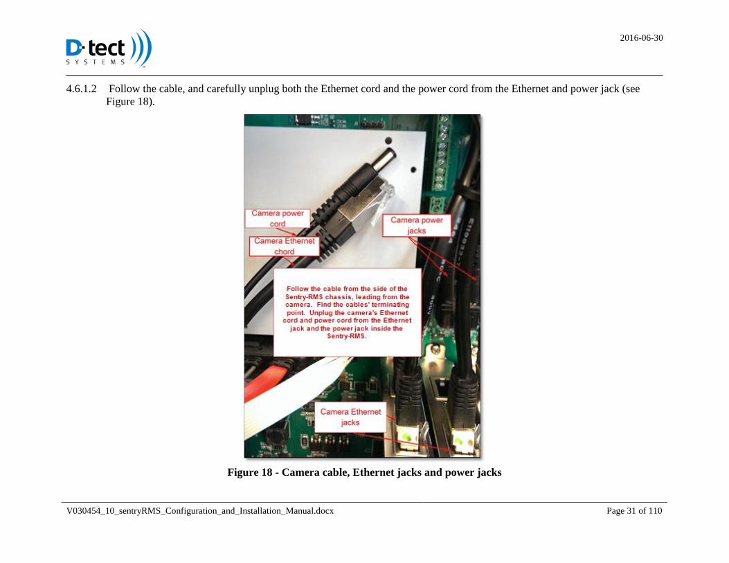
Follow the cable, and carefully unplug both the Ethernet cord and the power cord from the Ethernet and power jack (see 4.6.1.2
Figure 18).
Figure 18 - Camera cable, Ethernet jacks and power jacks
2016-06-30
V030454_10_sentryRMS_Configuration_and_Installation_Manual.docx Page 32 of 110
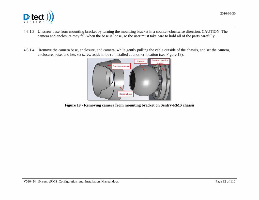
Unscrew base from mounting bracket by turning the mounting bracket in a counter-clockwise direction. CAUTION: The 4.6.1.3
camera and enclosure may fall when the base is loose, so the user must take care to hold all of the parts carefully.
Remove the camera base, enclosure, and camera, while gently pulling the cable outside of the chassis, and set the camera, 4.6.1.4
enclosure, base, and hex set screw aside to be re-installed at another location (see Figure 19).
Figure 19 - Removing camera from mounting bracket on Sentry-RMS chassis
2016-06-30
V030454_10_sentryRMS_Configuration_and_Installation_Manual.docx Page 33 of 110
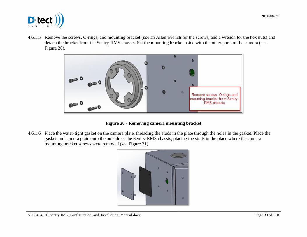
Remove the screws, O-rings, and mounting bracket (use an Allen wrench for the screws, and a wrench for the hex nuts) and 4.6.1.5
detach the bracket from the Sentry-RMS chassis. Set the mounting bracket aside with the other parts of the camera (see
Figure 20).
Figure 20 - Removing camera mounting bracket
Place the water-tight gasket on the camera plate, threading the studs in the plate through the holes in the gasket. Place the 4.6.1.6
gasket and camera plate onto the outside of the Sentry-RMS chassis, placing the studs in the place where the camera
mounting bracket screws were removed (see Figure 21).

2016-06-30
V030454_10_sentryRMS_Configuration_and_Installation_Manual.docx Page 34 of 110
Figure 21 - Placing water-tight gasket and camera plate on Sentry-RMS chassis
On the inside of the Sentry-RMS chassis, thread one hex nut on each of the camera plate studs using an adjustable crescent 4.6.1.7
wrench (see Figure 22). Tighten the nuts securely to ensure that water cannot leak into the chassis. Be sure to not overtighten
the nuts.
Figure 22 - Attaching hex nuts on to camera plate studs
If necessary, use the instructions (as described previously) for Mounting a Camera to mount the camera at another location.
2016-06-30
V030454_10_sentryRMS_Configuration_and_Installation_Manual.docx Page 35 of 110
4.7 Installing the Primary Backup Battery
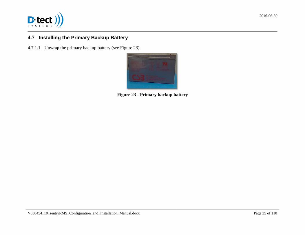
Unwrap the primary backup battery (see Figure 23). 4.7.1.1
Figure 23 - Primary backup battery
2016-06-30
V030454_10_sentryRMS_Configuration_and_Installation_Manual.docx Page 36 of 110
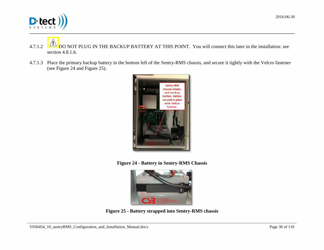
DO NOT PLUG IN THE BACKUP BATTERY AT THIS POINT. You will connect this later in the installation: see 4.7.1.2
section 4.8.1.6.
Place the primary backup battery in the bottom left of the Sentry-RMS chassis, and secure it tightly with the Velcro fastener 4.7.1.3
(see Figure 24 and Figure 25).
Figure 24 - Battery in Sentry-RMS Chassis
Figure 25 - Battery strapped into Sentry-RMS chassis
2016-06-30
V030454_10_sentryRMS_Configuration_and_Installation_Manual.docx Page 37 of 110
4.8 Wiring the User-Provided Input and Output Devices to the Sentry-RMS
Hardware included: N/A
Tools needed: Wire insulation strippers, wire cutters, small flat-blade or Phillips screwdriver for tightening terminal screws
User-required hardware: Insulated wire (16 to 26 AWG), end-of-line (EOL) resistors, devices, sensors, inputs, and outputs the
user desires to interface with the Sentry-RMS
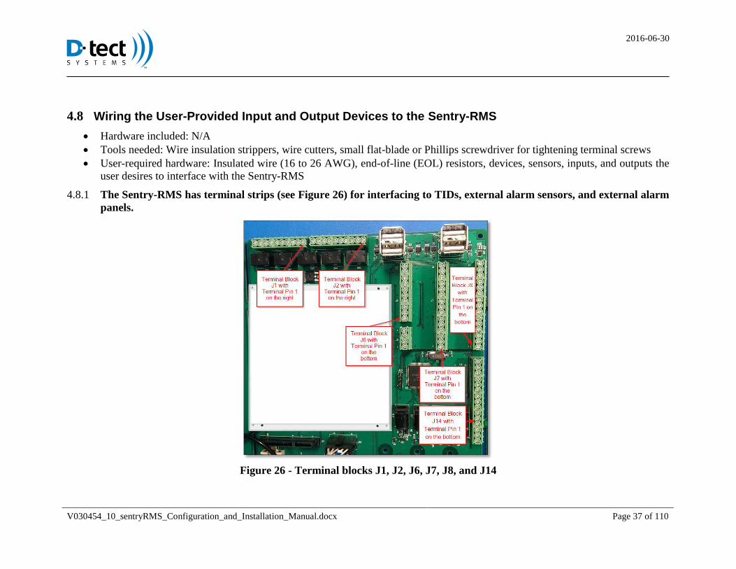
The Sentry-RMS has terminal strips (see Figure 26) for interfacing to TIDs, external alarm sensors, and external alarm 4.8.1
panels.
Figure 26 - Terminal blocks J1, J2, J6, J7, J8, and J14
2016-06-30
V030454_10_sentryRMS_Configuration_and_Installation_Manual.docx Page 38 of 110
Sentry-RMS Inputs 4.8.2
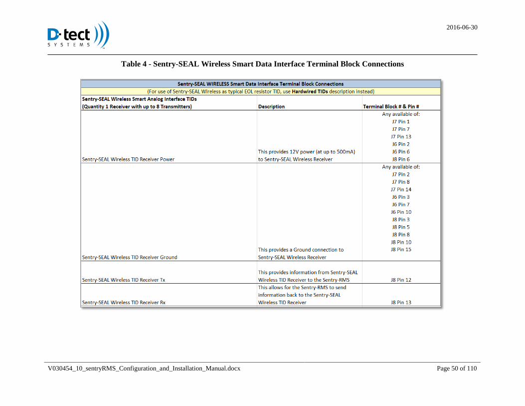
The Sentry-RMS supports two typical TIDs (e.g. TIDs with EOL resistor outputs), two Sentry-SEAL TIDs, one Sentry-SEAL
Wireless TID Receiver, with as many as eight Sentry-SEAL Wireless TID Transmitters, and up to three additional general-use
EOL resistor output sensors. (For more information on wiring, refer to terminal block connections tables below, the Sentry-
SEAL manual, and the Sentry-SEAL Wireless manual). Note that Sentry-SEAL and Sentry-SEAL Wireless TIDs can operate
using either Smart Interface connections or typical EOL resistor connections.
Wire all of the TIDs, including the Sentry-SEAL and Sentry-SEAL Wireless TIDs (as applicable), and general-purpose
external inputs into the Sentry-RMS. Use the diagrams and tables included following pages.
CAUTION: This process must be completed by an electrician or electrical technician or the configuration will not function
correctly.
All EOL resistor monitored circuits should be of the following pattern (note resistor values) as shown in the following sections.
2016-06-30
V030454_10_sentryRMS_Configuration_and_Installation_Manual.docx Page 39 of 110
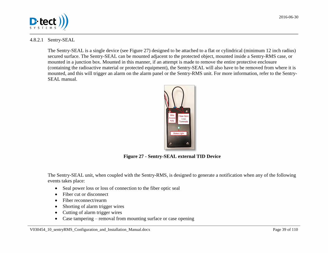
Sentry-SEAL 4.8.2.1
The Sentry-SEAL is a single device (see Figure 27) designed to be attached to a flat or cylindrical (minimum 12 inch radius)
secured surface. The Sentry-SEAL can be mounted adjacent to the protected object, mounted inside a Sentry-RMS case, or
mounted in a junction box. Mounted in this manner, if an attempt is made to remove the entire protective enclosure
(containing the radioactive material or protected equipment), the Sentry-SEAL will also have to be removed from where it is
mounted, and this will trigger an alarm on the alarm panel or the Sentry-RMS unit. For more information, refer to the Sentry-
SEAL manual.
Figure 27 - Sentry-SEAL external TID Device
The Sentry-SEAL unit, when coupled with the Sentry-RMS, is designed to generate a notification when any of the following
events takes place:
Seal power loss or loss of connection to the fiber optic seal
Fiber cut or disconnect
Fiber reconnect/rearm
Shorting of alarm trigger wires
Cutting of alarm trigger wires
Case tampering – removal from mounting surface or case opening
2016-06-30
V030454_10_sentryRMS_Configuration_and_Installation_Manual.docx Page 40 of 110
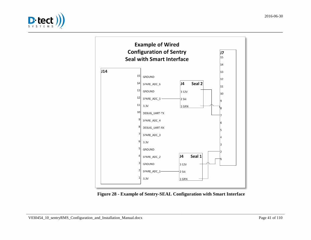
Wire the Sentry-SEAL using either the Smart Interface or EOL resistor interface as shown below.
CAUTION: Wiring both Smart Interface and EOL resistor interfaces at the same time may not allow for proper notifications.
Only one interface should be wired to the Sentry-RMS.
NOTE: The diagrams do not show connecting the necessary power and ground connections. Connect 3.3V or 12V power and
Ground as needed to the Sentry-RMS terminals marked as such.
2016-06-30
V030454_10_sentryRMS_Configuration_and_Installation_Manual.docx Page 41 of 110
Figure 28 - Example of Sentry-SEAL Configuration with Smart Interface
2016-06-30
V030454_10_sentryRMS_Configuration_and_Installation_Manual.docx Page 42 of 110
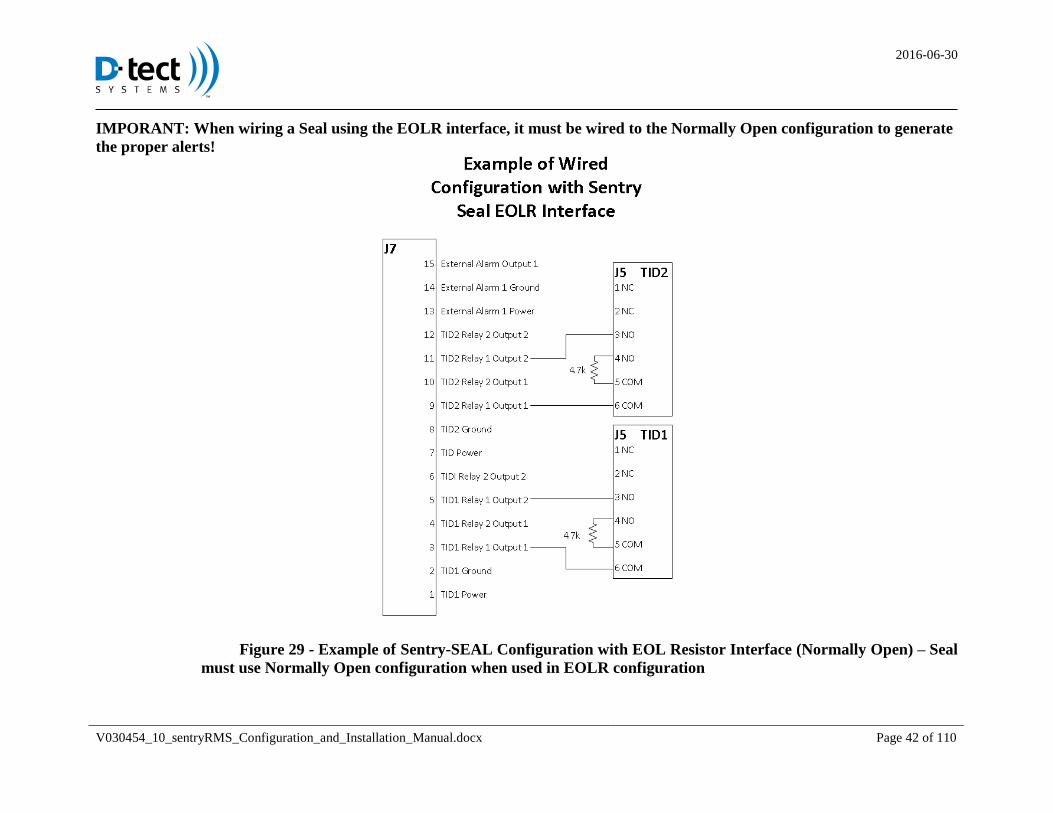
IMPORANT: When wiring a Seal using the EOLR interface, it must be wired to the Normally Open configuration to generate
the proper alerts!
Figure 29 - Example of Sentry-SEAL Configuration with EOL Resistor Interface (Normally Open) – Seal
must use Normally Open configuration when used in EOLR configuration
2016-06-30
V030454_10_sentryRMS_Configuration_and_Installation_Manual.docx Page 43 of 110
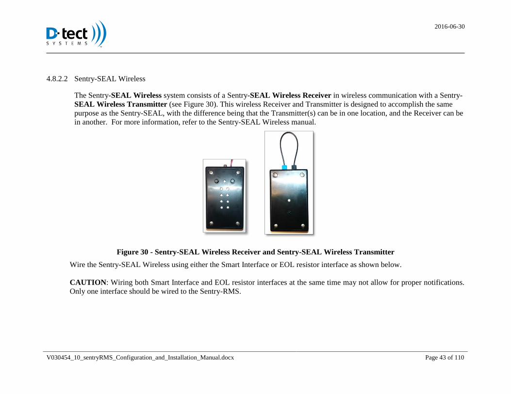
Sentry-SEAL Wireless 4.8.2.2
The Sentry-SEAL Wireless system consists of a Sentry-SEAL Wireless Receiver in wireless communication with a Sentry-
SEAL Wireless Transmitter (see Figure 30). This wireless Receiver and Transmitter is designed to accomplish the same
purpose as the Sentry-SEAL, with the difference being that the Transmitter(s) can be in one location, and the Receiver can be
in another. For more information, refer to the Sentry-SEAL Wireless manual.
Figure 30 - Sentry-SEAL Wireless Receiver and Sentry-SEAL Wireless Transmitter
Wire the Sentry-SEAL Wireless using either the Smart Interface or EOL resistor interface as shown below.
CAUTION: Wiring both Smart Interface and EOL resistor interfaces at the same time may not allow for proper notifications.
Only one interface should be wired to the Sentry-RMS.
2016-06-30
V030454_10_sentryRMS_Configuration_and_Installation_Manual.docx Page 44 of 110
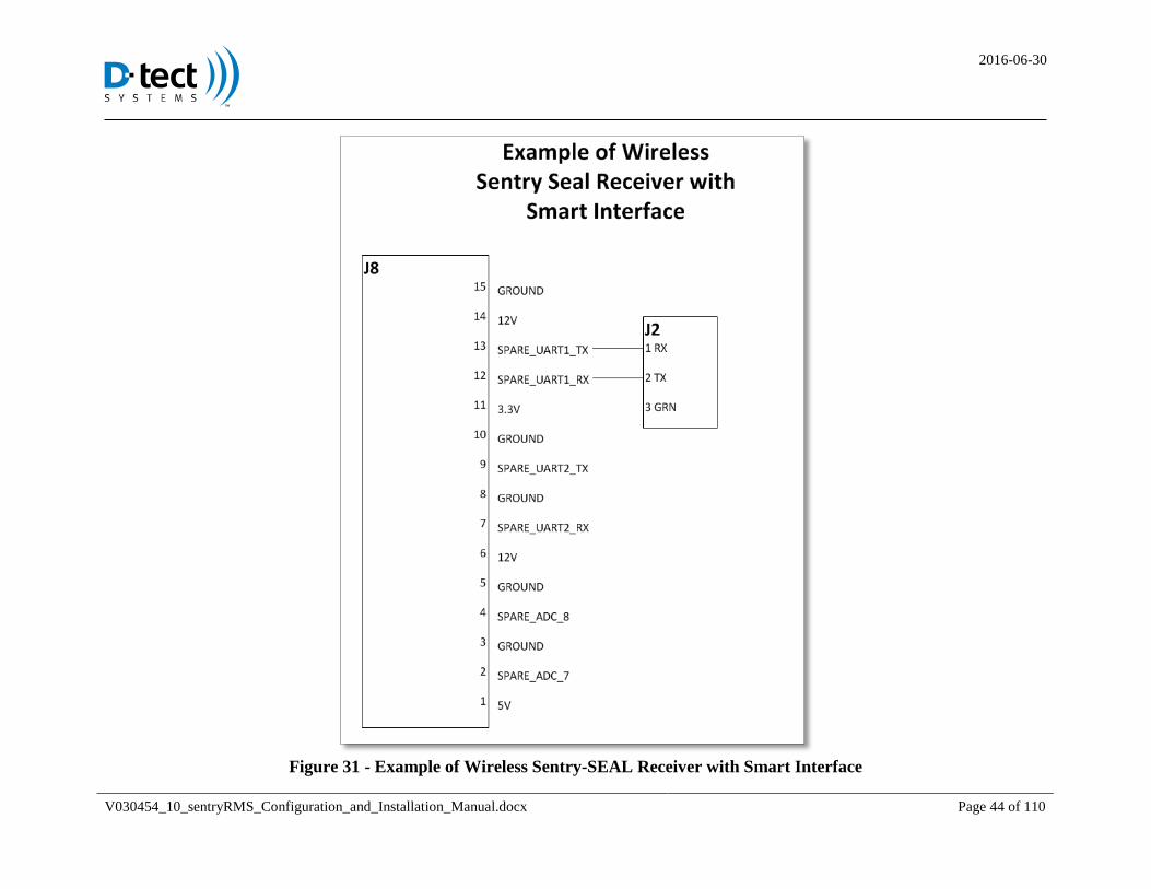
Figure 31 - Example of Wireless Sentry-SEAL Receiver with Smart Interface
2016-06-30
V030454_10_sentryRMS_Configuration_and_Installation_Manual.docx Page 45 of 110
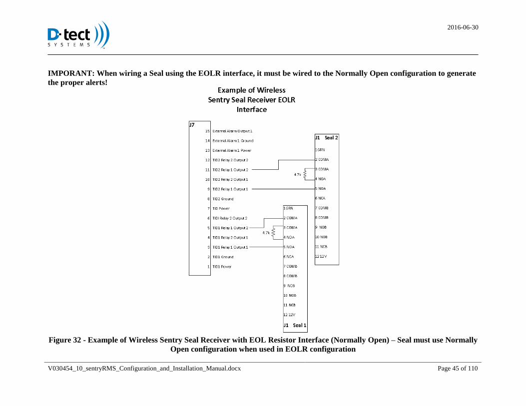
IMPORANT: When wiring a Seal using the EOLR interface, it must be wired to the Normally Open configuration to generate
the proper alerts!
Figure 32 - Example of Wireless Sentry Seal Receiver with EOL Resistor Interface (Normally Open) – Seal must use Normally
Open configuration when used in EOLR configuration
2016-06-30
V030454_10_sentryRMS_Configuration_and_Installation_Manual.docx Page 46 of 110
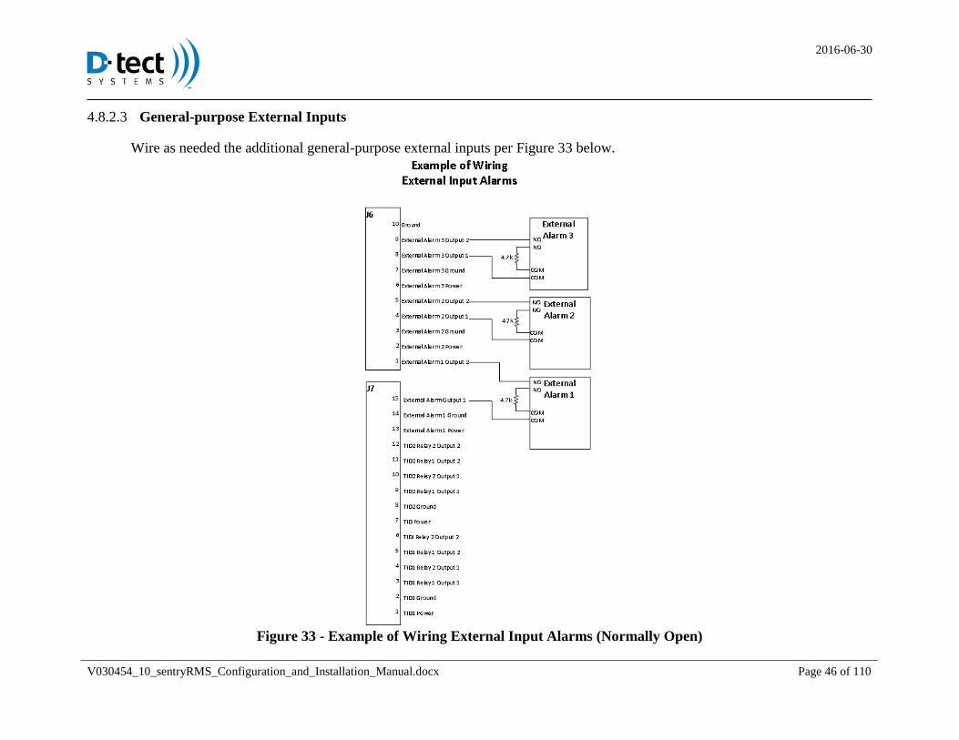
General-purpose External Inputs 4.8.2.3
Wire as needed the additional general-purpose external inputs per Figure 33 below.
Figure 33 - Example of Wiring External Input Alarms (Normally Open)
2016-06-30
V030454_10_sentryRMS_Configuration_and_Installation_Manual.docx Page 47 of 110
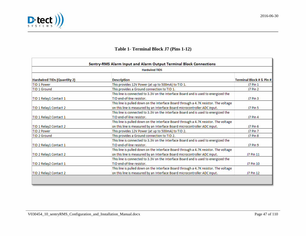
Table 1- Terminal Block J7 (Pins 1-12)
2016-06-30
V030454_10_sentryRMS_Configuration_and_Installation_Manual.docx Page 48 of 110
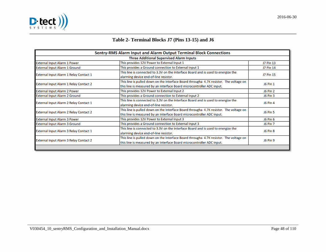
Table 2- Terminal Blocks J7 (Pins 13-15) and J6
2016-06-30
V030454_10_sentryRMS_Configuration_and_Installation_Manual.docx Page 49 of 110
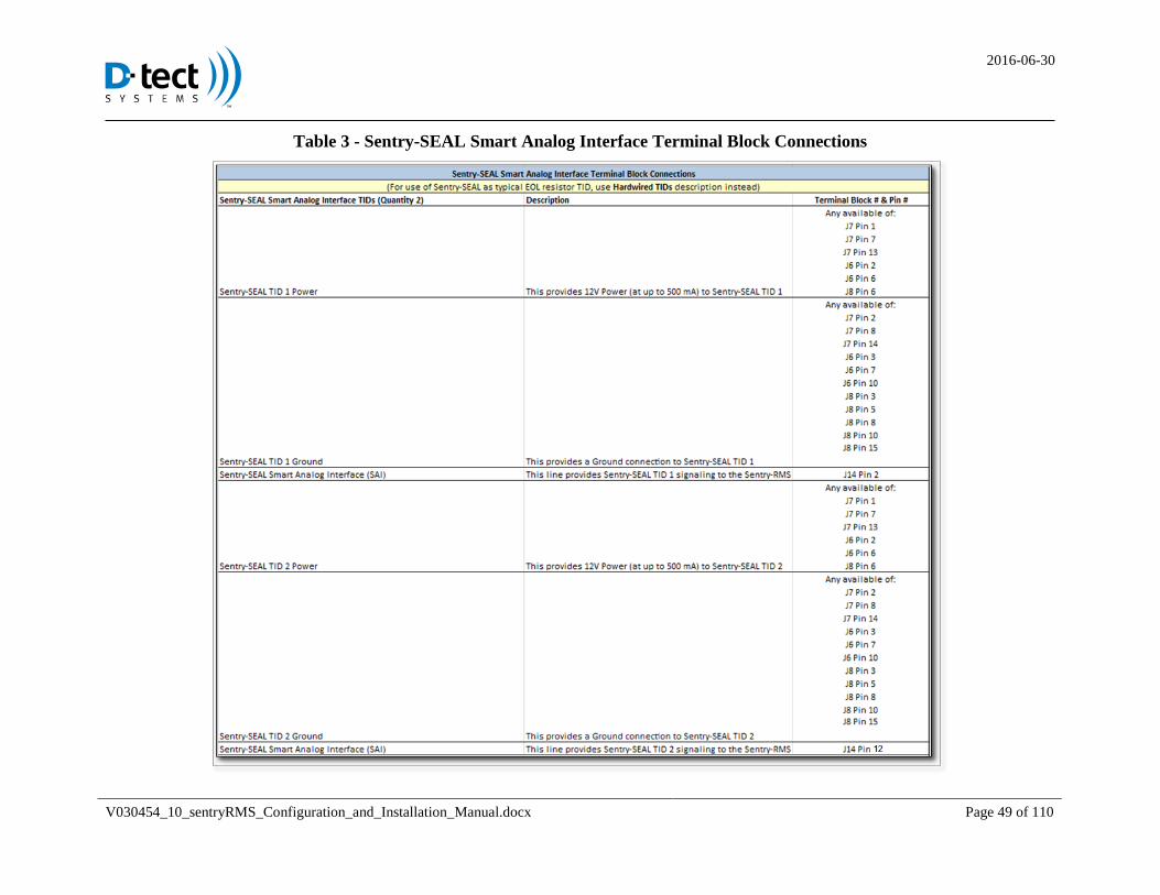
Table 3 - Sentry-SEAL Smart Analog Interface Terminal Block Connections
2016-06-30
V030454_10_sentryRMS_Configuration_and_Installation_Manual.docx Page 50 of 110
Table 4 - Sentry-SEAL Wireless Smart Data Interface Terminal Block Connections
2016-06-30
V030454_10_sentryRMS_Configuration_and_Installation_Manual.docx Page 51 of 110
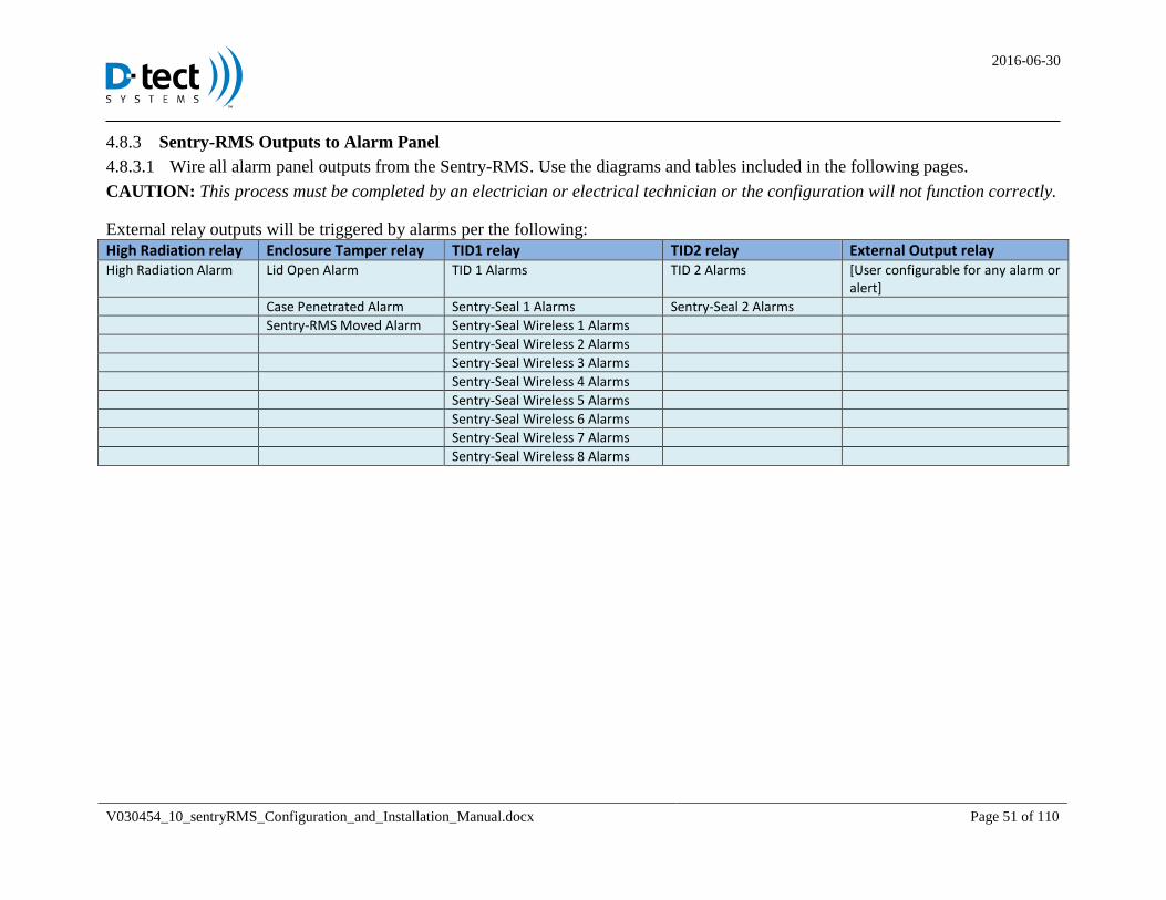
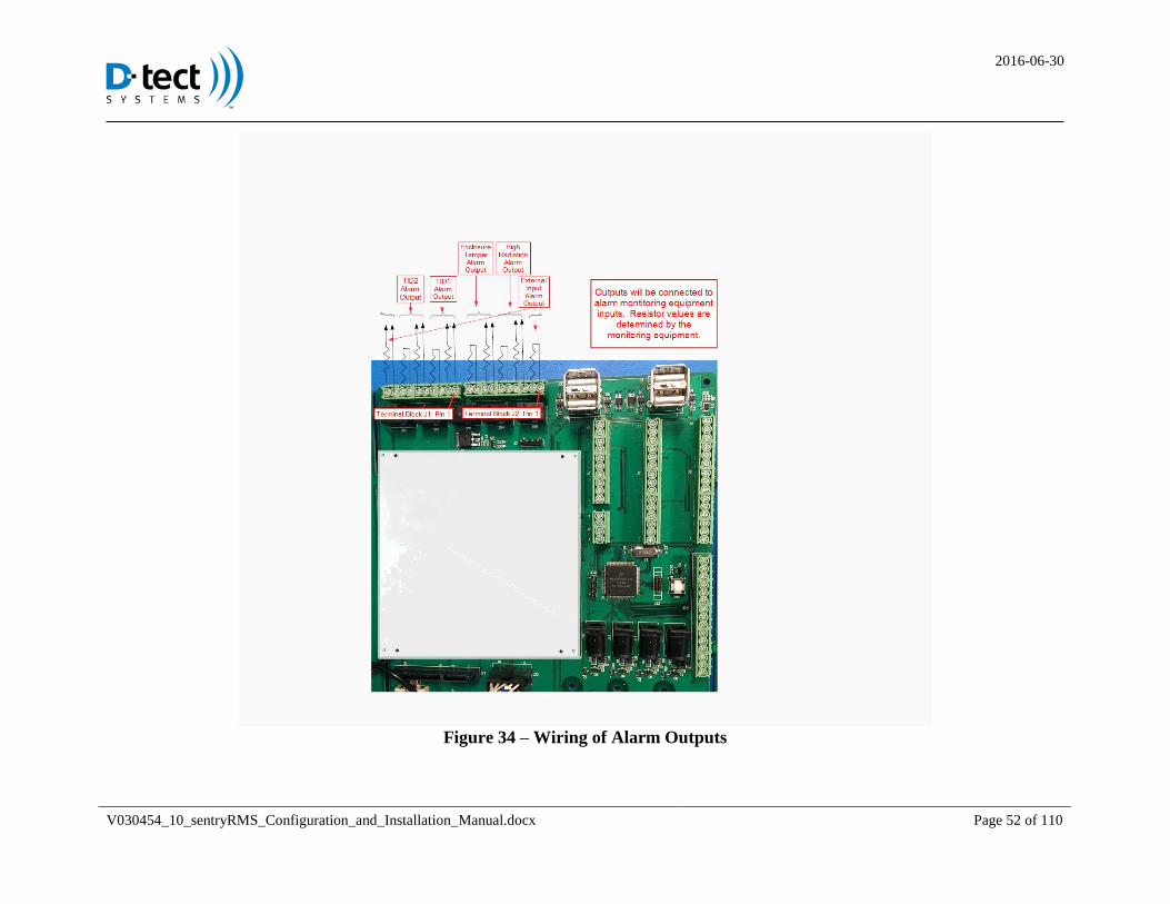
Sentry-RMS Outputs to Alarm Panel 4.8.3
Wire all alarm panel outputs from the Sentry-RMS. Use the diagrams and tables included in the following pages. 4.8.3.1
CAUTION: This process must be completed by an electrician or electrical technician or the configuration will not function correctly.
External relay outputs will be triggered by alarms per the following:
High Radiation relay Enclosure Tamper relay TID1 relay TID2 relay External Output relay High Radiation Alarm Lid Open Alarm TID 1 Alarms TID 2 Alarms [User configurable for any alarm or
alert]
Case Penetrated Alarm Sentry-Seal 1 Alarms Sentry-Seal 2 Alarms
Sentry-RMS Moved Alarm Sentry-Seal Wireless 1 Alarms
Sentry-Seal Wireless 2 Alarms
Sentry-Seal Wireless 3 Alarms
Sentry-Seal Wireless 4 Alarms
Sentry-Seal Wireless 5 Alarms
Sentry-Seal Wireless 6 Alarms
Sentry-Seal Wireless 7 Alarms
Sentry-Seal Wireless 8 Alarms
2016-06-30
V030454_10_sentryRMS_Configuration_and_Installation_Manual.docx Page 52 of 110
Figure 34 – Wiring of Alarm Outputs

2016-06-30
V030454_10_sentryRMS_Configuration_and_Installation_Manual.docx Page 53 of 110
Figure 35 – Example of Wiring Alarm Outputs
2016-06-30
V030454_10_sentryRMS_Configuration_and_Installation_Manual.docx Page 54 of 110
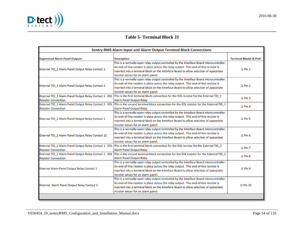
Table 5- Terminal Block J1
2016-06-30
V030454_10_sentryRMS_Configuration_and_Installation_Manual.docx Page 55 of 110
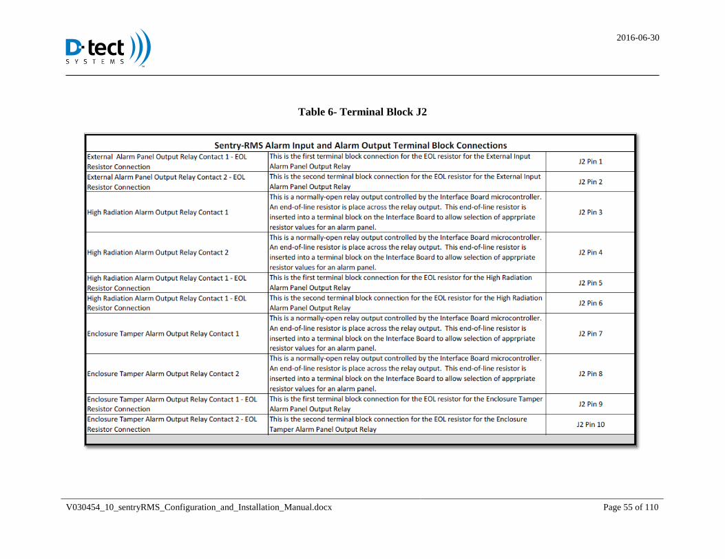
Table 6- Terminal Block J2
2016-06-30
V030454_10_sentryRMS_Configuration_and_Installation_Manual.docx Page 56 of 110
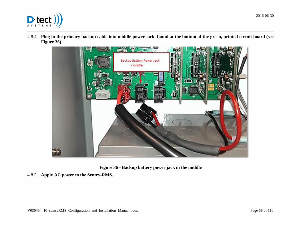
Plug in the primary backup cable into middle power jack, found at the bottom of the green, printed circuit board (see 4.8.4
Figure 36).
Figure 36 - Backup battery power jack in the middle
Apply AC power to the Sentry-RMS. 4.8.5

2016-06-30
V030454_10_sentryRMS_Configuration_and_Installation_Manual.docx Page 57 of 110
4.9 Tamper Sensors
Light Sensors 4.9.1
The Sentry-RMS unit is equipped with multiple tamper sensors. Light sensors are located in multiple places within the 4.9.1.1
interior of the unit. If outside ambient light is detected within the unit (such as opening the front panel or drilling the outside
box), the unit will alarm. NOTE: Make precautions to not allow ambient light through the top conduits.
Back Plate Pressure Button 4.9.2
A back-plate pressure button is located at the back of the Sentry-RMS unit. After installation of the unit, if the unit is 4.9.2.1
removed from the wall, the unit will alarm. NOTE: Be sure to use the correct screws as specified in 4.1 or the tamper button
will not function correctly.
Figure 37 - Back Plate Pressure Button
2016-06-30
V030454_10_sentryRMS_Configuration_and_Installation_Manual.docx Page 58 of 110
5 Preparation for Software Setup of the Sentry-RMS Configuration Tool (SCT)
5.1 Option 1 - Connecting to the site via network
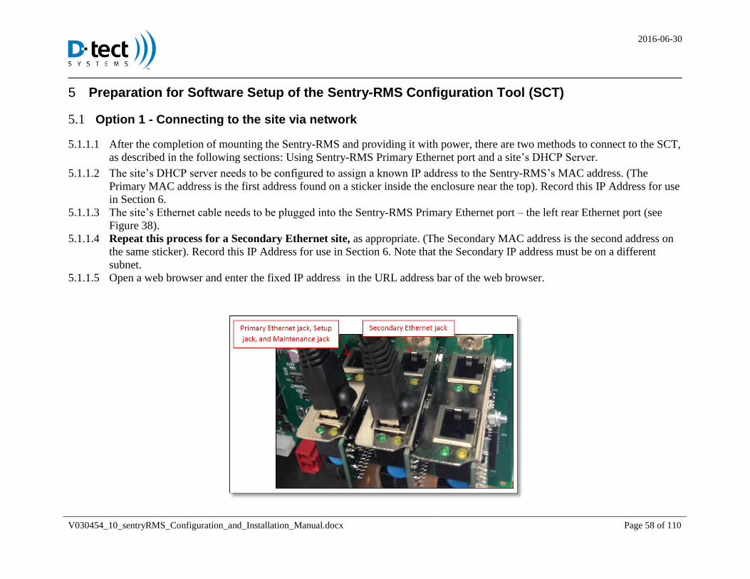
After the completion of mounting the Sentry-RMS and providing it with power, there are two methods to connect to the SCT, 5.1.1.1
as described in the following sections: Using Sentry-RMS Primary Ethernet port and a site’s DHCP Server.
The site’s DHCP server needs to be configured to assign a known IP address to the Sentry-RMS’s MAC address. (The 5.1.1.2
Primary MAC address is the first address found on a sticker inside the enclosure near the top). Record this IP Address for use
in Section 6.
The site’s Ethernet cable needs to be plugged into the Sentry-RMS Primary Ethernet port – the left rear Ethernet port (see 5.1.1.3
Figure 38).
Repeat this process for a Secondary Ethernet site, as appropriate. (The Secondary MAC address is the second address on 5.1.1.4
the same sticker). Record this IP Address for use in Section 6. Note that the Secondary IP address must be on a different
subnet.
Open a web browser and enter the fixed IP address in the URL address bar of the web browser. 5.1.1.5
2016-06-30
V030454_10_sentryRMS_Configuration_and_Installation_Manual.docx Page 59 of 110
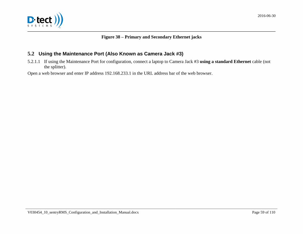
Figure 38 – Primary and Secondary Ethernet jacks
5.2 Using the Maintenance Port (Also Known as Camera Jack #3)
If using the Maintenance Port for configuration, connect a laptop to Camera Jack #3 using a standard Ethernet cable (not 5.2.1.1
the splitter).
Open a web browser and enter IP address 192.168.233.1 in the URL address bar of the web browser.
2016-06-30
V030454_10_sentryRMS_Configuration_and_Installation_Manual.docx Page 60 of 110
6 Sentry-RMS Configuration Tool – Login, Description and Usage
6.1 Login to SCT and Event Viewer
To begin the setup of the software of the SCT, open an Internet browser on the computer, and type in the IP address recorded
in Section 5.
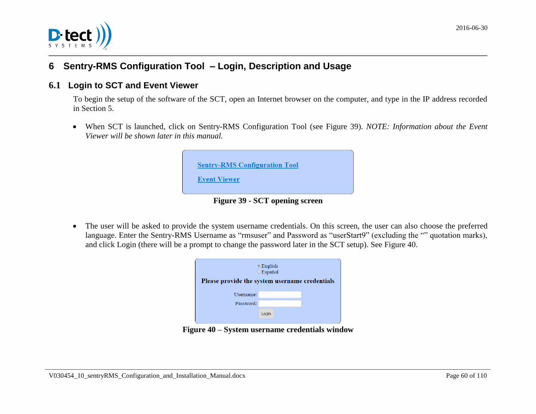
When SCT is launched, click on Sentry-RMS Configuration Tool (see Figure 39). NOTE: Information about the Event
Viewer will be shown later in this manual.
Figure 39 - SCT opening screen
The user will be asked to provide the system username credentials. On this screen, the user can also choose the preferred
language. Enter the Sentry-RMS Username as “rmsuser” and Password as “userStart9” (excluding the “” quotation marks),
and click Login (there will be a prompt to change the password later in the SCT setup). See Figure 40.
Figure 40 – System username credentials window
2016-06-30
V030454_10_sentryRMS_Configuration_and_Installation_Manual.docx Page 61 of 110
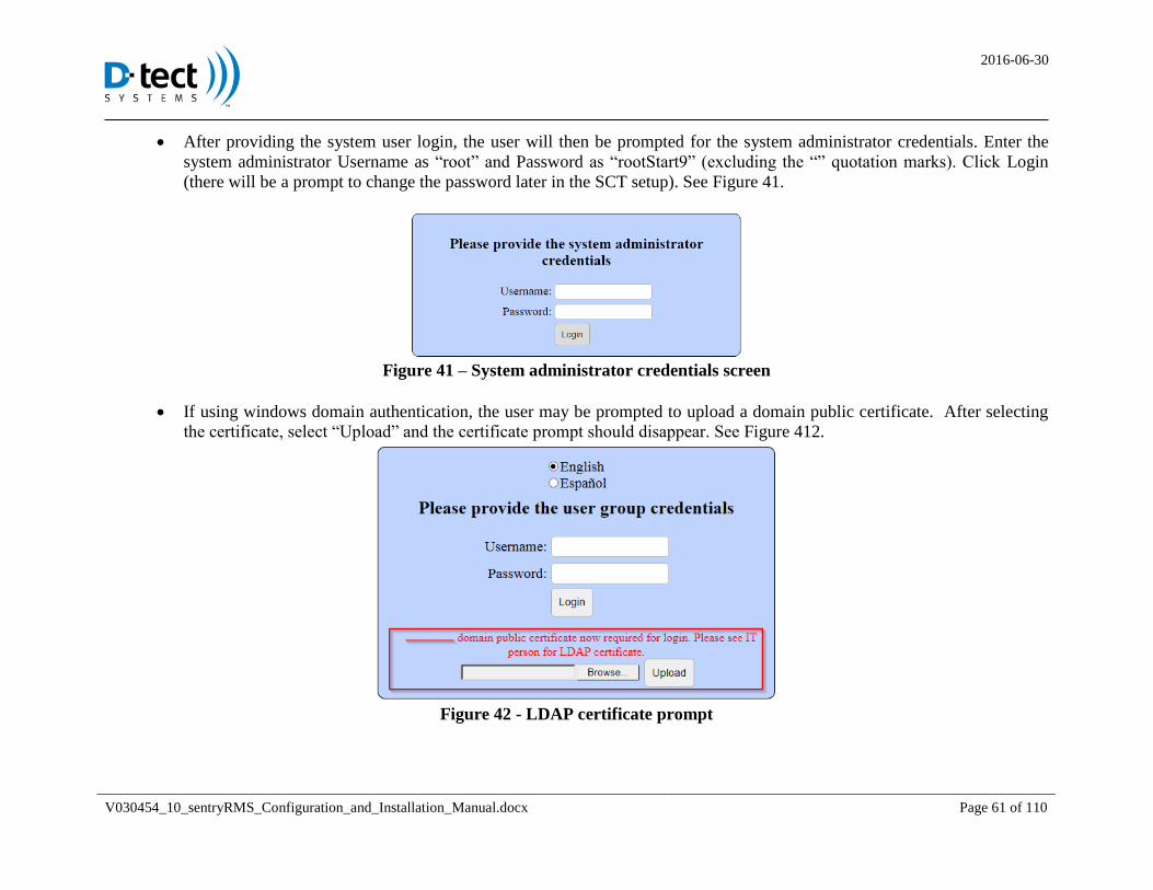
After providing the system user login, the user will then be prompted for the system administrator credentials. Enter the
system administrator Username as “root” and Password as “rootStart9” (excluding the “” quotation marks). Click Login
(there will be a prompt to change the password later in the SCT setup). See Figure 41.
Figure 41 – System administrator credentials screen
If using windows domain authentication, the user may be prompted to upload a domain public certificate. After selecting
the certificate, select “Upload” and the certificate prompt should disappear. See Figure 412.
Figure 42 - LDAP certificate prompt
2016-06-30
V030454_10_sentryRMS_Configuration_and_Installation_Manual.docx Page 62 of 110
6.2 SCT Description and Usage
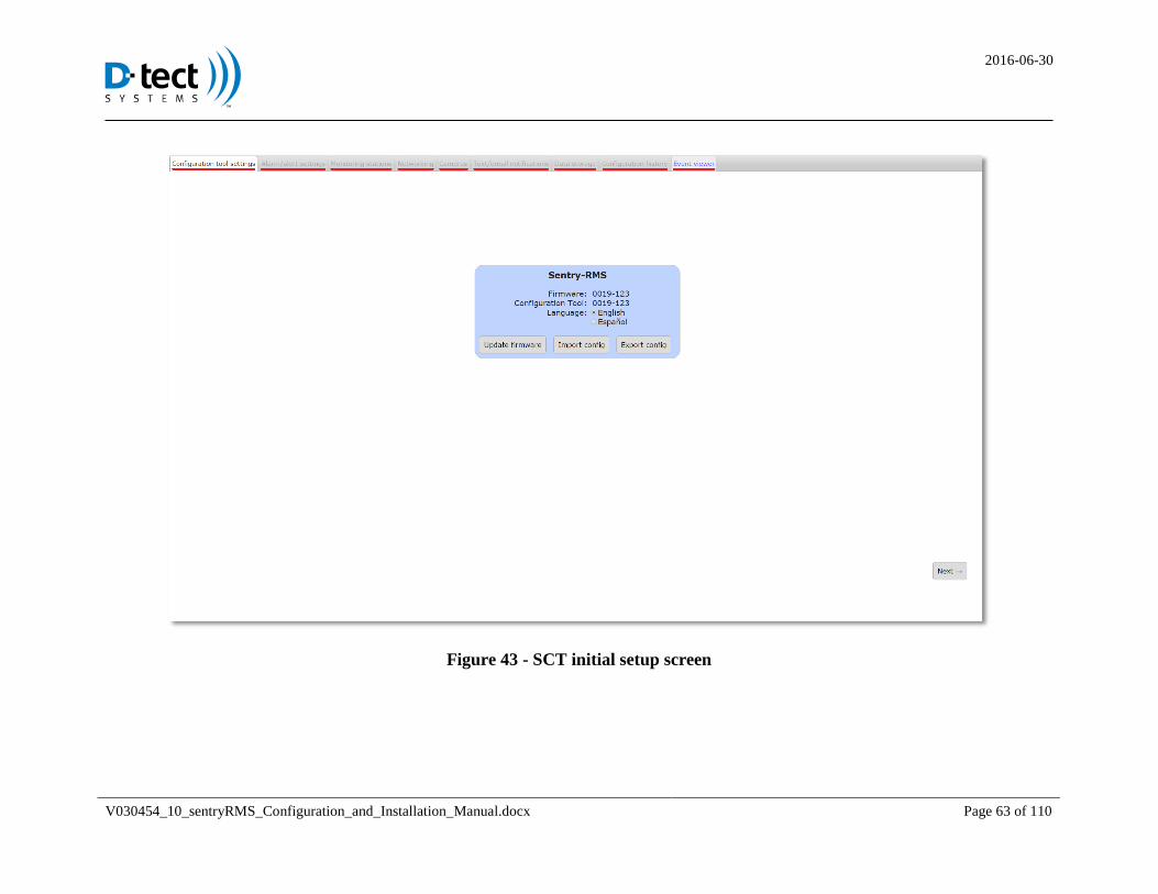
The first window of the SCT will open to the Configuration Tool Settings tab. During this initial setup, all other tabs will be
greyed out. A Configuration Wizard will walk the user through the setup process by allowing the user to complete one tab, and
then to click the “Next” button at the bottom of the page. The following is a list of the tabs, and a brief description of the
purpose of each tab (see Figure 43).
Configuration tool settings: This tab allows the user to update firmware, import a configuration file, export a configuration
file, and change the preferred language.
Alarm/alert settings: This tab allows the user to input customized input and output sensors, set levels for radiation, and view
battery and disk thresholds.
Monitoring stations: This tab allows the user to associate the Sentry-RMS with monitoring stations (input the Display Names
of monitoring stations, set the station type, and copy corresponding Security Tokens).
Networking: This tab allows the user to insert the Primary and Secondary Ethernet port configurations, set the name of the
Sentry-RMS, set State of Health periods, upload SSL certificates, set mail server information (for email and text notifications),
set system passwords, and configure the web authentication method.
Cameras: This tab allows the user to insert the names given to the cameras for a particular Sentry-RMS device. This tab is
also used to control which camera saves video clips for specific alarms.
Text/email notifications: This tab shows the events that can be sent via email or text, and allows the user to add people to be
notified when specific events are generated by the Sentry-RMS.
Data storage: This tab allows the user to determine how long video data will be stored and configure a backup server.
Configuration history: This tab allows the user to see what configuration changes have been made to the Sentry-RMS and
who made the changes
Event viewer: This tab launches the Event Viewer, which shows the user the Sentry-RMS State of Health (SoH), details of
past Alarms and Alerts, and Logs of all events.
2016-06-30
V030454_10_sentryRMS_Configuration_and_Installation_Manual.docx Page 63 of 110
Figure 43 - SCT initial setup screen
2016-06-30
V030454_10_sentryRMS_Configuration_and_Installation_Manual.docx Page 64 of 110
7 Instructions on Setting Up the SCT
7.1 Configuration Tool Settings
The first tab allows the user to update firmware, import a configuration file, export a configuration file, and change the preferred
language.
IMPORTANT: It is important that you update the Sentry-RMS to the latest firmware when configuring the hardware. See
details in the next section.
2016-06-30
V030454_10_sentryRMS_Configuration_and_Installation_Manual.docx Page 65 of 110
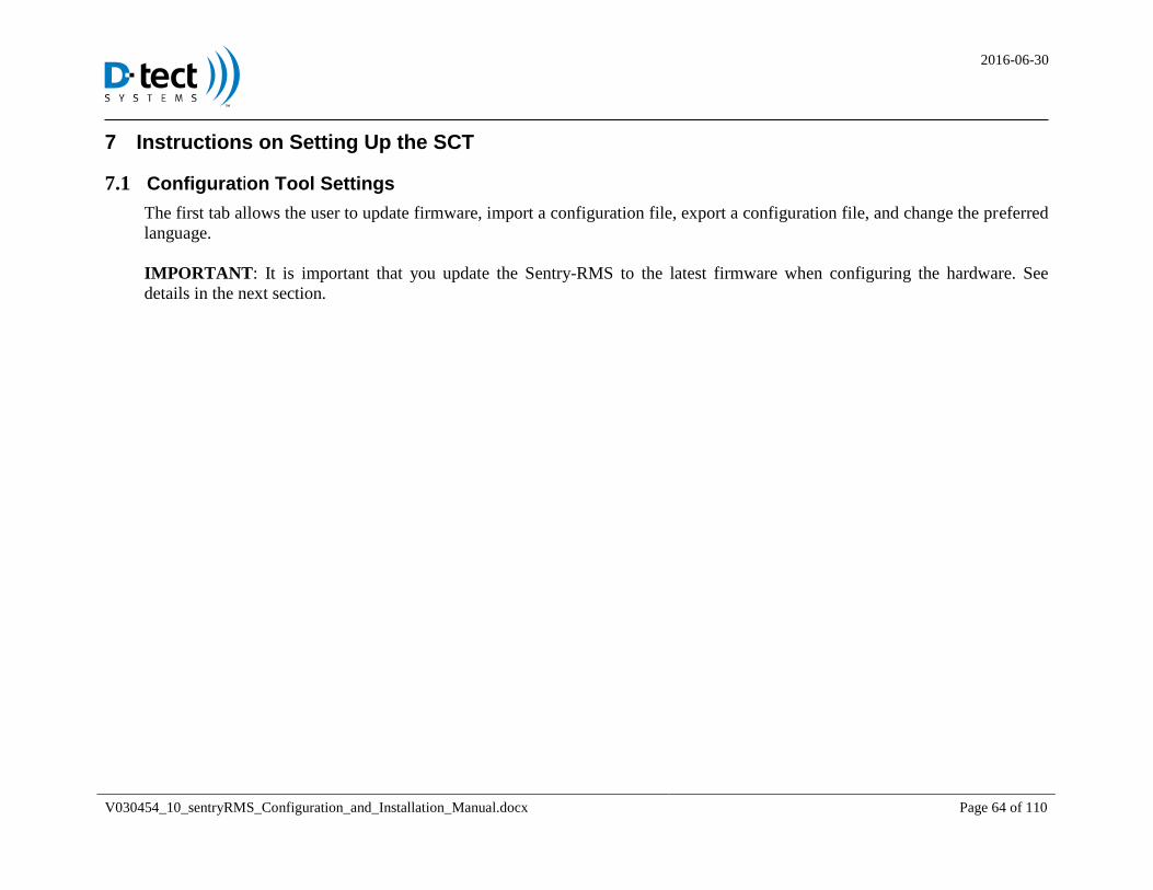
Update Firmware 7.1.1 To get the most recent firmware update, contact the authorized third-party installers of the firmware manufacturer. After the 7.1.1.1
user has a copy of the newest firmware saved on the computer (or other storage device), the user will click on the “Update
Firmware” button.
A window will open allowing the user to browse for the firmware update by choosing a file, and browsing through the user’s 7.1.1.2
computer (or other storage device) for the saved file (see Figure 44). After choosing the update, click the Update button. This
process will take a few minutes. After the update is complete, the user will see a message indicating whether the update was
successful.
If not, run the update process again. 7.1.1.3
IMPORTANT: You cannot update firmware if the Sentry-RMS is running on battery. Ensure that you have A/C power
before performing an update.
Figure 44 - Firmware update screen
2016-06-30
V030454_10_sentryRMS_Configuration_and_Installation_Manual.docx Page 66 of 110
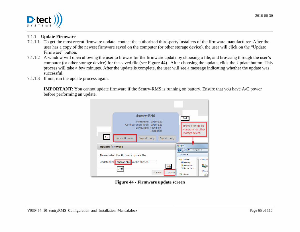
Export Configurations 7.1.2
(Skip this section when configuring the first unit)
Exporting is useful when the user needs to configure another Sentry-RMS. 7.1.2.1
After the first Sentry-RMS has been configured, the user has the ability to save the configuration by using the Export 7.1.2.2
function. Before the Export can be completed, the user has to choose a password and type the password in two Password
boxes (see Figure 45). This exported file and associated password must be available later to any user needing to use the
Import function later.
Figure 45 - Exporting a configuration
After typing in the passwords, click Export. A file labeled config.enc will be downloaded onto the computer. Save the 7.1.2.3
Exported file to a known location on the computer or another storage device.
2016-06-30
V030454_10_sentryRMS_Configuration_and_Installation_Manual.docx Page 67 of 110
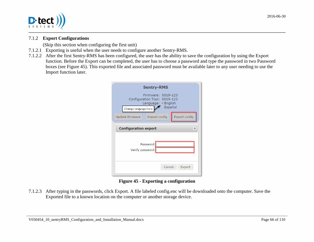
Import Configurations 7.1.3
(Skip this section when configuring the first unit)
Importing the configuration file will allow the SCT site to be populated with previously-defined configurations without 7.1.3.1
having to repeat the entire process completed in a previous SCT setup.
Click on the Import Config button, enter the Configuration Password used when the export was saved. Navigate to the saved 7.1.3.2
SCT configuration saved on the computer or other storage device (see Figure 46). Choose the configuration file, then click
“Import.”
After Importing for a second Sentry-RMS, the user can change items such as the IP Addresses, Monitor Names, and other 7.1.3.3
items to modify the Sentry-RMS configuration to correlate with the second Sentry-RMS. Security Tokens are not exported
and are unique for each Sentry-RMS.
Figure 46 - Importing a configuration
2016-06-30
V030454_10_sentryRMS_Configuration_and_Installation_Manual.docx Page 68 of 110
After the successful Import, click the “Next” button on the lower right corner of the screen when all applicable steps have 7.1.3.4
been taken on this tab.
Note that even when you import from an existing configuration, some parameters will still need to be uniquely modified
(Sentry-RMS Name, IP Addresses, etc).
2016-06-30
V030454_10_sentryRMS_Configuration_and_Installation_Manual.docx Page 69 of 110
Alarm/Alert Settings tab 7.1.4
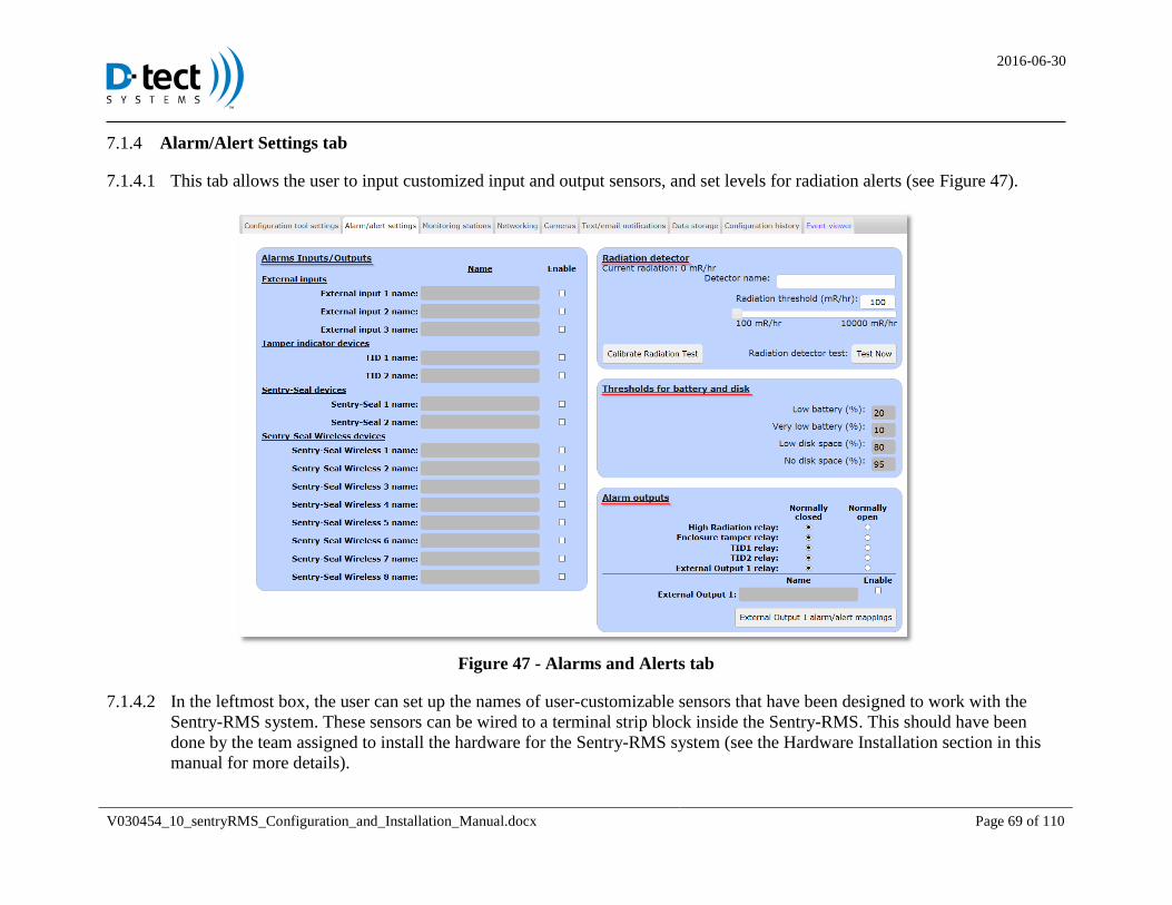
This tab allows the user to input customized input and output sensors, and set levels for radiation alerts (see Figure 47). 7.1.4.1
Figure 47 - Alarms and Alerts tab
In the leftmost box, the user can set up the names of user-customizable sensors that have been designed to work with the 7.1.4.2
Sentry-RMS system. These sensors can be wired to a terminal strip block inside the Sentry-RMS. This should have been
done by the team assigned to install the hardware for the Sentry-RMS system (see the Hardware Installation section in this
manual for more details).
2016-06-30
V030454_10_sentryRMS_Configuration_and_Installation_Manual.docx Page 70 of 110
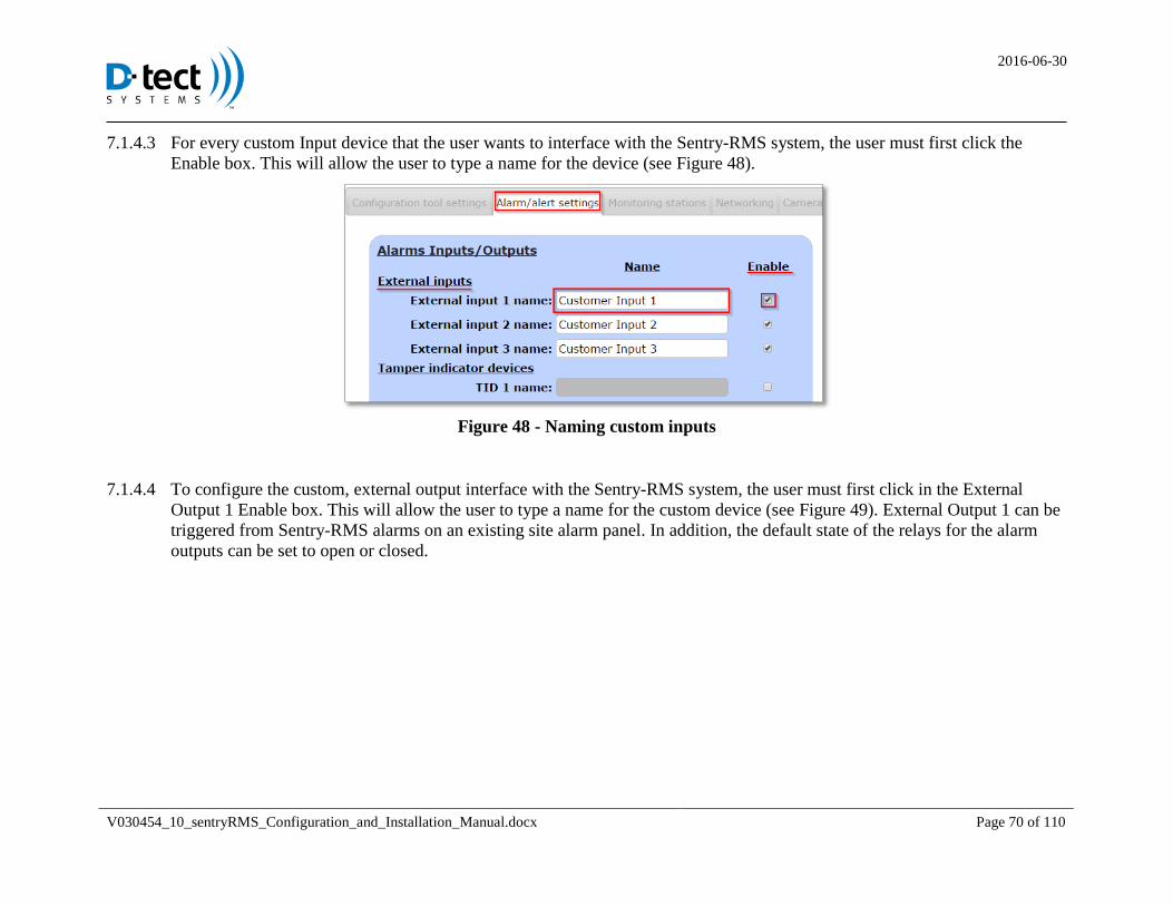
For every custom Input device that the user wants to interface with the Sentry-RMS system, the user must first click the 7.1.4.3
Enable box. This will allow the user to type a name for the device (see Figure 48).
Figure 48 - Naming custom inputs
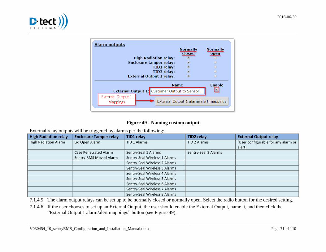
To configure the custom, external output interface with the Sentry-RMS system, the user must first click in the External 7.1.4.4
Output 1 Enable box. This will allow the user to type a name for the custom device (see Figure 49). External Output 1 can be
triggered from Sentry-RMS alarms on an existing site alarm panel. In addition, the default state of the relays for the alarm
outputs can be set to open or closed.
2016-06-30
V030454_10_sentryRMS_Configuration_and_Installation_Manual.docx Page 71 of 110
Figure 49 - Naming custom output
External relay outputs will be triggered by alarms per the following:
High Radiation relay Enclosure Tamper relay TID1 relay TID2 relay External Output relay High Radiation Alarm Lid Open Alarm TID 1 Alarms TID 2 Alarms [User configurable for any alarm or
alert]
Case Penetrated Alarm Sentry-Seal 1 Alarms Sentry-Seal 2 Alarms
Sentry-RMS Moved Alarm Sentry-Seal Wireless 1 Alarms
Sentry-Seal Wireless 2 Alarms
Sentry-Seal Wireless 3 Alarms
Sentry-Seal Wireless 4 Alarms
Sentry-Seal Wireless 5 Alarms
Sentry-Seal Wireless 6 Alarms
Sentry-Seal Wireless 7 Alarms
Sentry-Seal Wireless 8 Alarms
The alarm output relays can be set up to be normally closed or normally open. Select the radio button for the desired setting. 7.1.4.5
If the user chooses to set up an External Output, the user should enable the External Output, name it, and then click the 7.1.4.6
“External Output 1 alarm/alert mappings” button (see Figure 49).
2016-06-30
V030454_10_sentryRMS_Configuration_and_Installation_Manual.docx Page 72 of 110
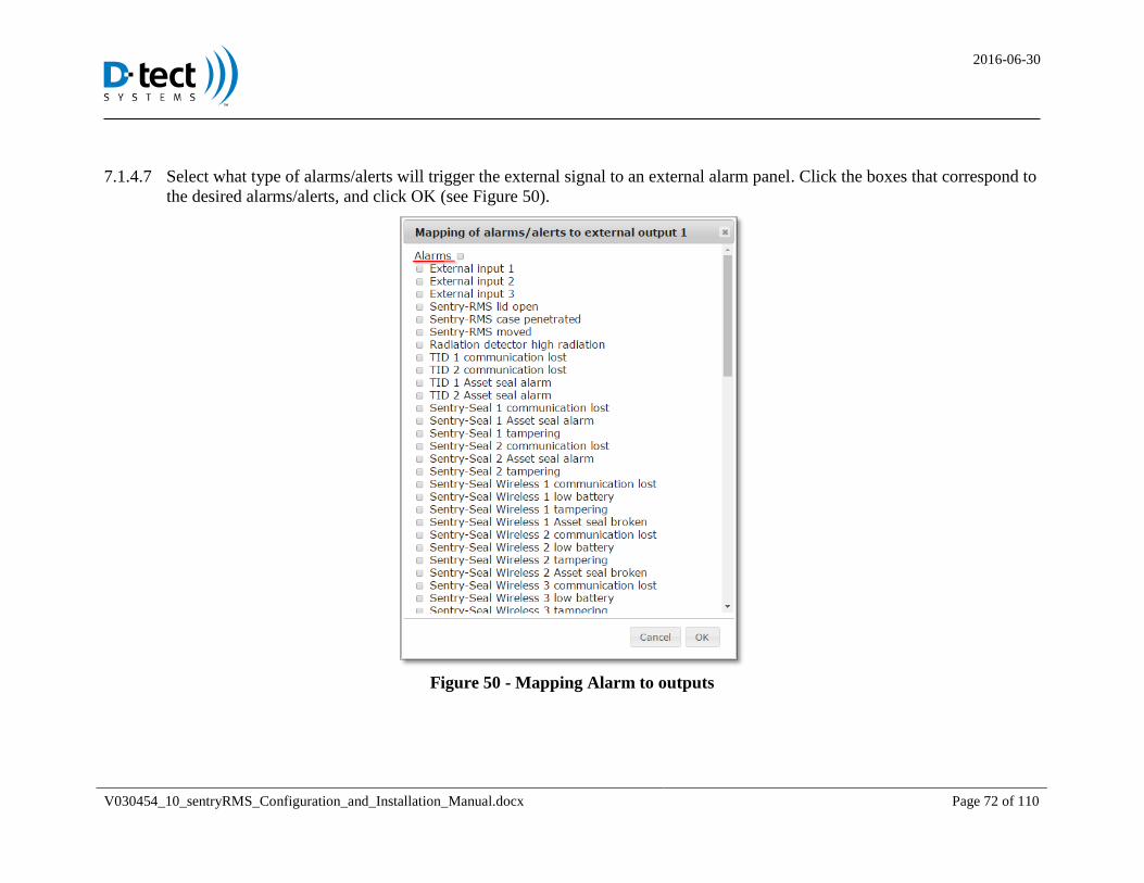
Select what type of alarms/alerts will trigger the external signal to an external alarm panel. Click the boxes that correspond to 7.1.4.7
the desired alarms/alerts, and click OK (see Figure 50).
Figure 50 - Mapping Alarm to outputs
2016-06-30
V030454_10_sentryRMS_Configuration_and_Installation_Manual.docx Page 73 of 110
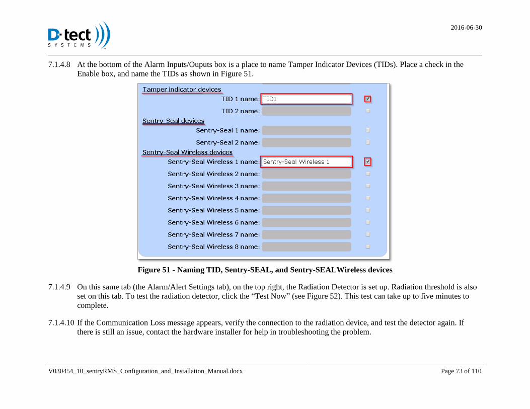
At the bottom of the Alarm Inputs/Ouputs box is a place to name Tamper Indicator Devices (TIDs). Place a check in the 7.1.4.8
Enable box, and name the TIDs as shown in Figure 51.
Figure 51 - Naming TID, Sentry-SEAL, and Sentry-SEALWireless devices
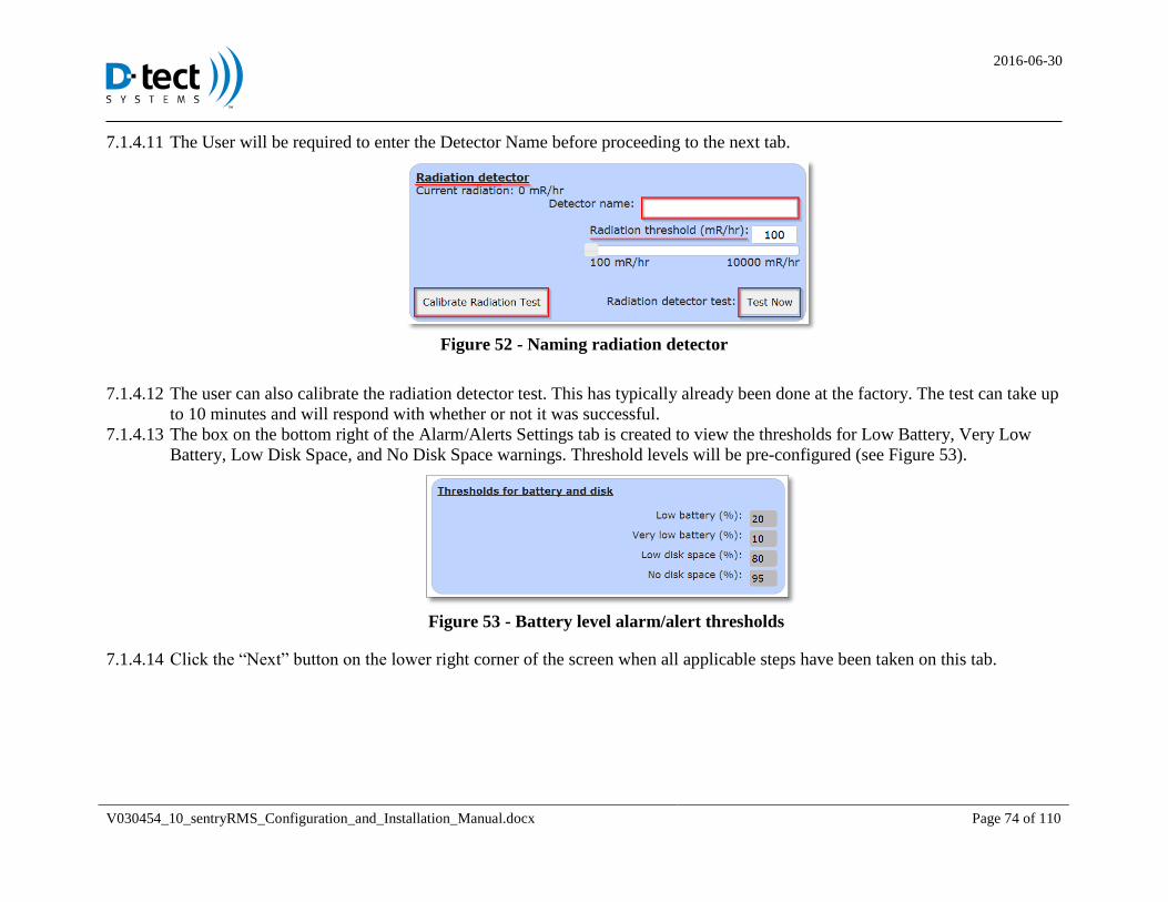
On this same tab (the Alarm/Alert Settings tab), on the top right, the Radiation Detector is set up. Radiation threshold is also 7.1.4.9
set on this tab. To test the radiation detector, click the “Test Now” (see Figure 52). This test can take up to five minutes to
complete.
If the Communication Loss message appears, verify the connection to the radiation device, and test the detector again. If 7.1.4.10
there is still an issue, contact the hardware installer for help in troubleshooting the problem.
2016-06-30
V030454_10_sentryRMS_Configuration_and_Installation_Manual.docx Page 74 of 110
The User will be required to enter the Detector Name before proceeding to the next tab. 7.1.4.11
Figure 52 - Naming radiation detector
The user can also calibrate the radiation detector test. This has typically already been done at the factory. The test can take up 7.1.4.12
to 10 minutes and will respond with whether or not it was successful.
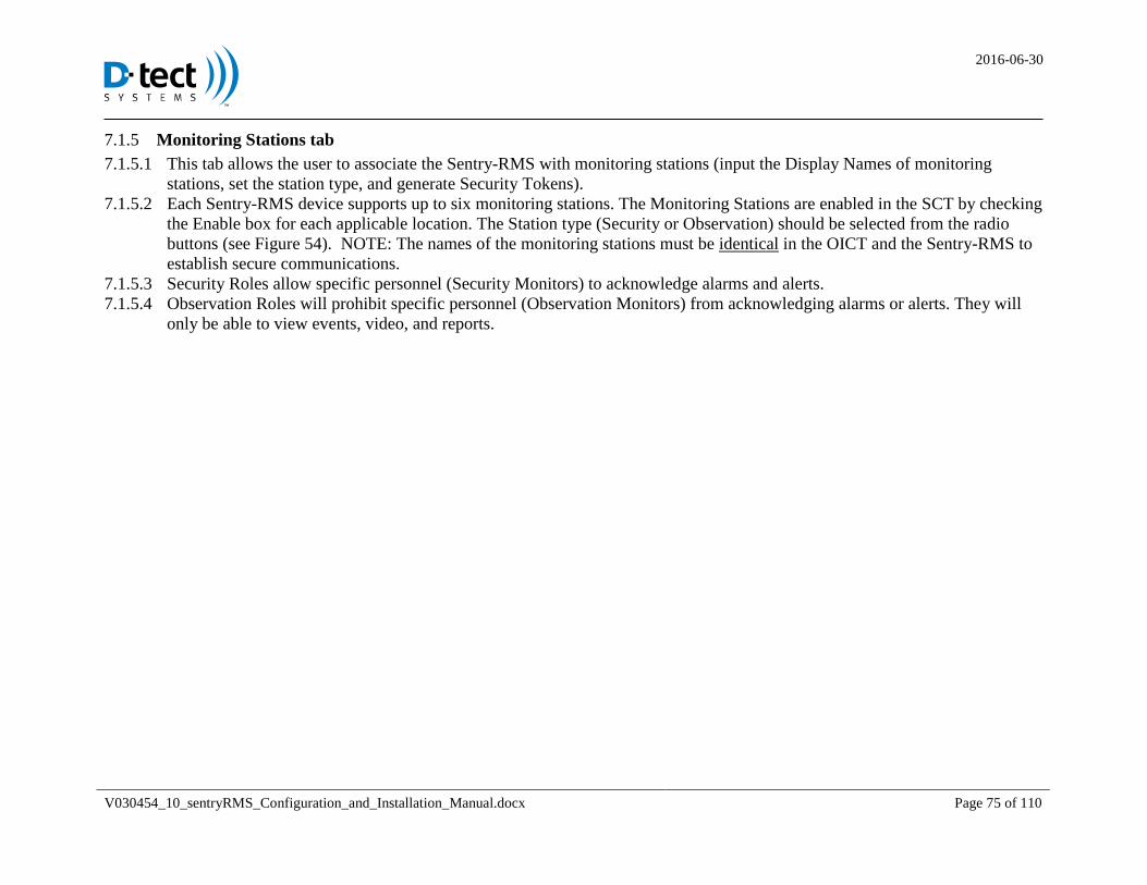
The box on the bottom right of the Alarm/Alerts Settings tab is created to view the thresholds for Low Battery, Very Low 7.1.4.13
Battery, Low Disk Space, and No Disk Space warnings. Threshold levels will be pre-configured (see Figure 53).
Figure 53 - Battery level alarm/alert thresholds
Click the “Next” button on the lower right corner of the screen when all applicable steps have been taken on this tab. 7.1.4.14
2016-06-30
V030454_10_sentryRMS_Configuration_and_Installation_Manual.docx Page 75 of 110
Monitoring Stations tab 7.1.5
This tab allows the user to associate the Sentry-RMS with monitoring stations (input the Display Names of monitoring 7.1.5.1
stations, set the station type, and generate Security Tokens).
Each Sentry-RMS device supports up to six monitoring stations. The Monitoring Stations are enabled in the SCT by checking 7.1.5.2
the Enable box for each applicable location. The Station type (Security or Observation) should be selected from the radio
buttons (see Figure 54). NOTE: The names of the monitoring stations must be identical in the OICT and the Sentry-RMS to
establish secure communications.
Security Roles allow specific personnel (Security Monitors) to acknowledge alarms and alerts. 7.1.5.3
Observation Roles will prohibit specific personnel (Observation Monitors) from acknowledging alarms or alerts. They will 7.1.5.4
only be able to view events, video, and reports.
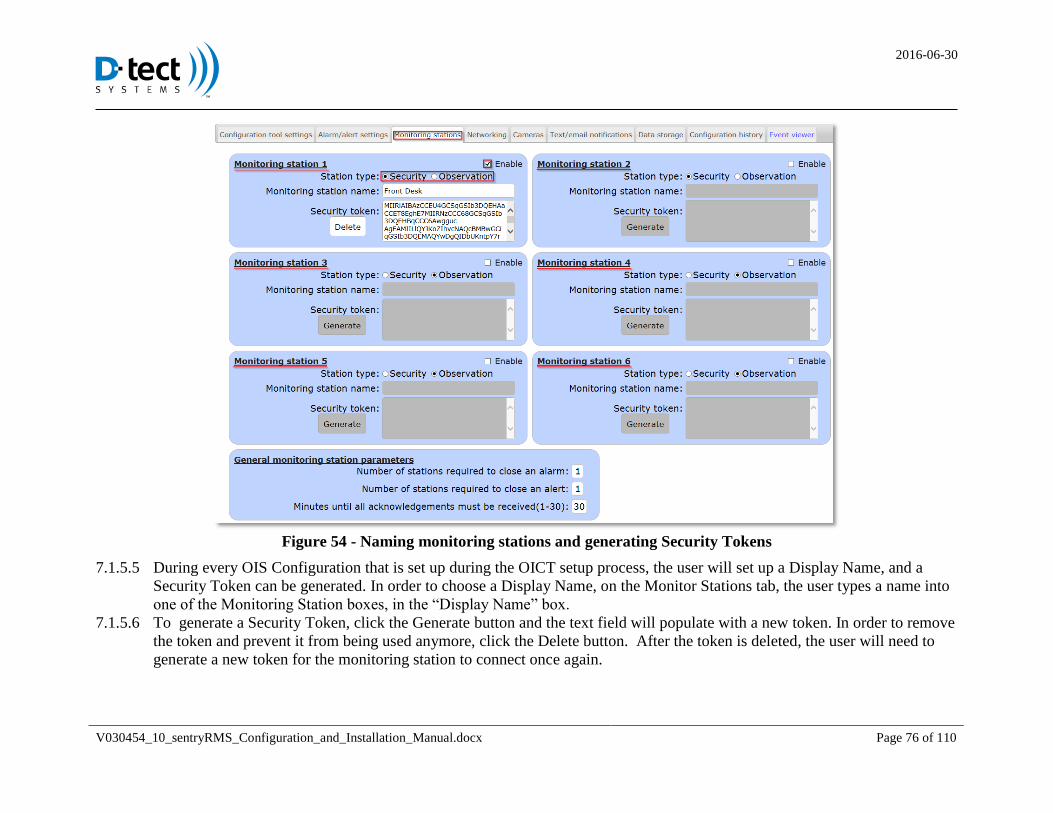
2016-06-30
V030454_10_sentryRMS_Configuration_and_Installation_Manual.docx Page 76 of 110
Figure 54 - Naming monitoring stations and generating Security Tokens
During every OIS Configuration that is set up during the OICT setup process, the user will set up a Display Name, and a 7.1.5.5
Security Token can be generated. In order to choose a Display Name, on the Monitor Stations tab, the user types a name into
one of the Monitoring Station boxes, in the “Display Name” box.
To generate a Security Token, click the Generate button and the text field will populate with a new token. In order to remove 7.1.5.6
the token and prevent it from being used anymore, click the Delete button. After the token is deleted, the user will need to
generate a new token for the monitoring station to connect once again.
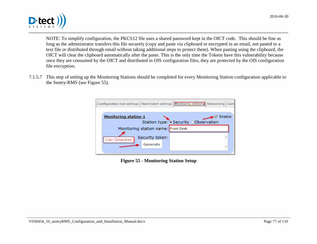
2016-06-30
V030454_10_sentryRMS_Configuration_and_Installation_Manual.docx Page 77 of 110
NOTE: To simplify configuration, the PKCS12 file uses a shared password kept in the OICT code. This should be fine as
long as the administrator transfers this file securely (copy and paste via clipboard or encrypted in an email, not pasted to a
text file or distributed through email without taking additional steps to protect them). When pasting using the clipboard, the
OICT will clear the clipboard automatically after the paste. This is the only time the Tokens have this vulnerability because
once they are consumed by the OICT and distributed in OIS configuration files, they are protected by the OIS configuration
file encryption.
This step of setting up the Monitoring Stations should be completed for every Monitoring Station configuration applicable to 7.1.5.7
the Sentry-RMS (see Figure 55).
Figure 55 - Monitoring Station Setup
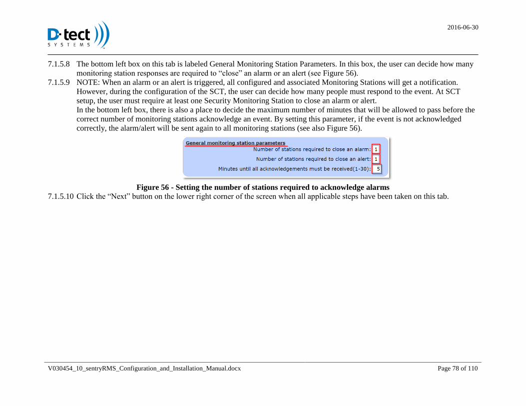
2016-06-30
V030454_10_sentryRMS_Configuration_and_Installation_Manual.docx Page 78 of 110
The bottom left box on this tab is labeled General Monitoring Station Parameters. In this box, the user can decide how many 7.1.5.8
monitoring station responses are required to “close” an alarm or an alert (see Figure 56).
NOTE: When an alarm or an alert is triggered, all configured and associated Monitoring Stations will get a notification. 7.1.5.9
However, during the configuration of the SCT, the user can decide how many people must respond to the event. At SCT
setup, the user must require at least one Security Monitoring Station to close an alarm or alert.
In the bottom left box, there is also a place to decide the maximum number of minutes that will be allowed to pass before the
correct number of monitoring stations acknowledge an event. By setting this parameter, if the event is not acknowledged
correctly, the alarm/alert will be sent again to all monitoring stations (see also Figure 56).
Figure 56 - Setting the number of stations required to acknowledge alarms
Click the “Next” button on the lower right corner of the screen when all applicable steps have been taken on this tab. 7.1.5.10
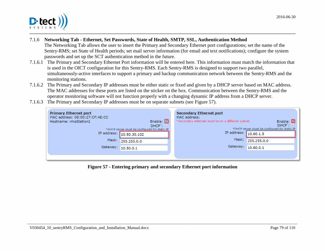
2016-06-30
V030454_10_sentryRMS_Configuration_and_Installation_Manual.docx Page 79 of 110
Networking Tab - Ethernet, Set Passwords, State of Health, SMTP, SSL, Authentication Method 7.1.6The Networking Tab allows the user to insert the Primary and Secondary Ethernet port configurations; set the name of the
Sentry-RMS; set State of Health periods; set mail server information (for email and text notifications); configure the system
passwords and set up the SCT authentication method in the future.
The Primary and Secondary Ethernet Port information will be entered here. This information must match the information that 7.1.6.1
is used in the OICT configuration for this Sentry-RMS. Each Sentry-RMS is designed to support two parallel,
simultaneously-active interfaces to support a primary and backup communication network between the Sentry-RMS and the
monitoring stations.
The Primary and Secondary IP addresses must be either static or fixed and given by a DHCP server based on MAC address. 7.1.6.2
The MAC addresses for these ports are listed on the sticker on the box. Communication between the Sentry-RMS and the
operator monitoring software will not function properly with a changing dynamic IP address from a DHCP server.
The Primary and Secondary IP addresses must be on separate subnets (see Figure 57). 7.1.6.3
Figure 57 - Entering primary and secondary Ethernet port information
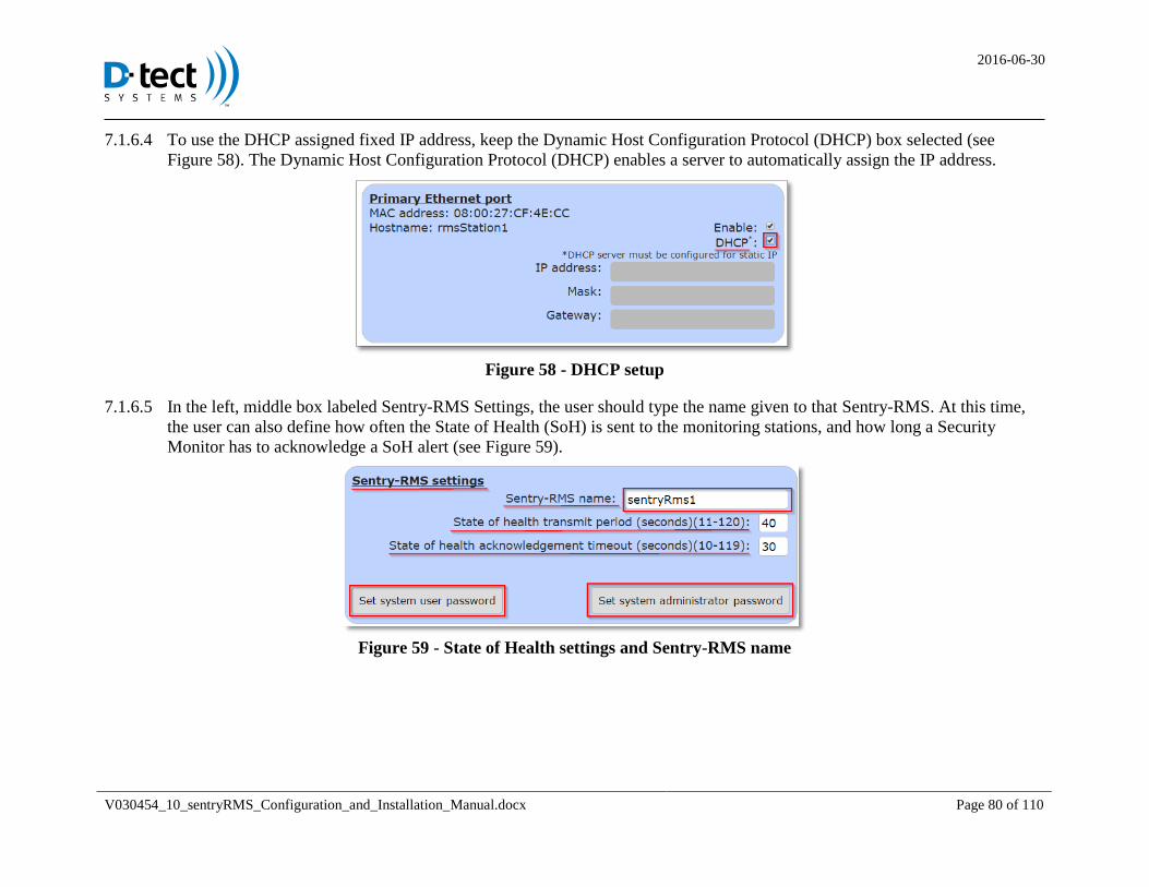
2016-06-30
V030454_10_sentryRMS_Configuration_and_Installation_Manual.docx Page 80 of 110
To use the DHCP assigned fixed IP address, keep the Dynamic Host Configuration Protocol (DHCP) box selected (see 7.1.6.4
Figure 58). The Dynamic Host Configuration Protocol (DHCP) enables a server to automatically assign the IP address.
Figure 58 - DHCP setup
In the left, middle box labeled Sentry-RMS Settings, the user should type the name given to that Sentry-RMS. At this time, 7.1.6.5
the user can also define how often the State of Health (SoH) is sent to the monitoring stations, and how long a Security
Monitor has to acknowledge a SoH alert (see Figure 59).
Figure 59 - State of Health settings and Sentry-RMS name
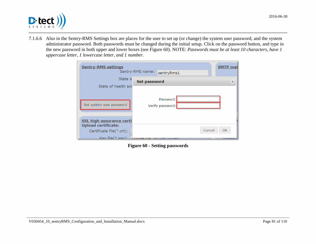
2016-06-30
V030454_10_sentryRMS_Configuration_and_Installation_Manual.docx Page 81 of 110
Also in the Sentry-RMS Settings box are places for the user to set up (or change) the system user password, and the system 7.1.6.6
administrator password. Both passwords must be changed during the initial setup. Click on the password button, and type in
the new password in both upper and lower boxes (see Figure 60). NOTE: Passwords must be at least 10 characters, have 1
uppercase letter, 1 lowercase letter, and 1 number.
Figure 60 - Setting passwords
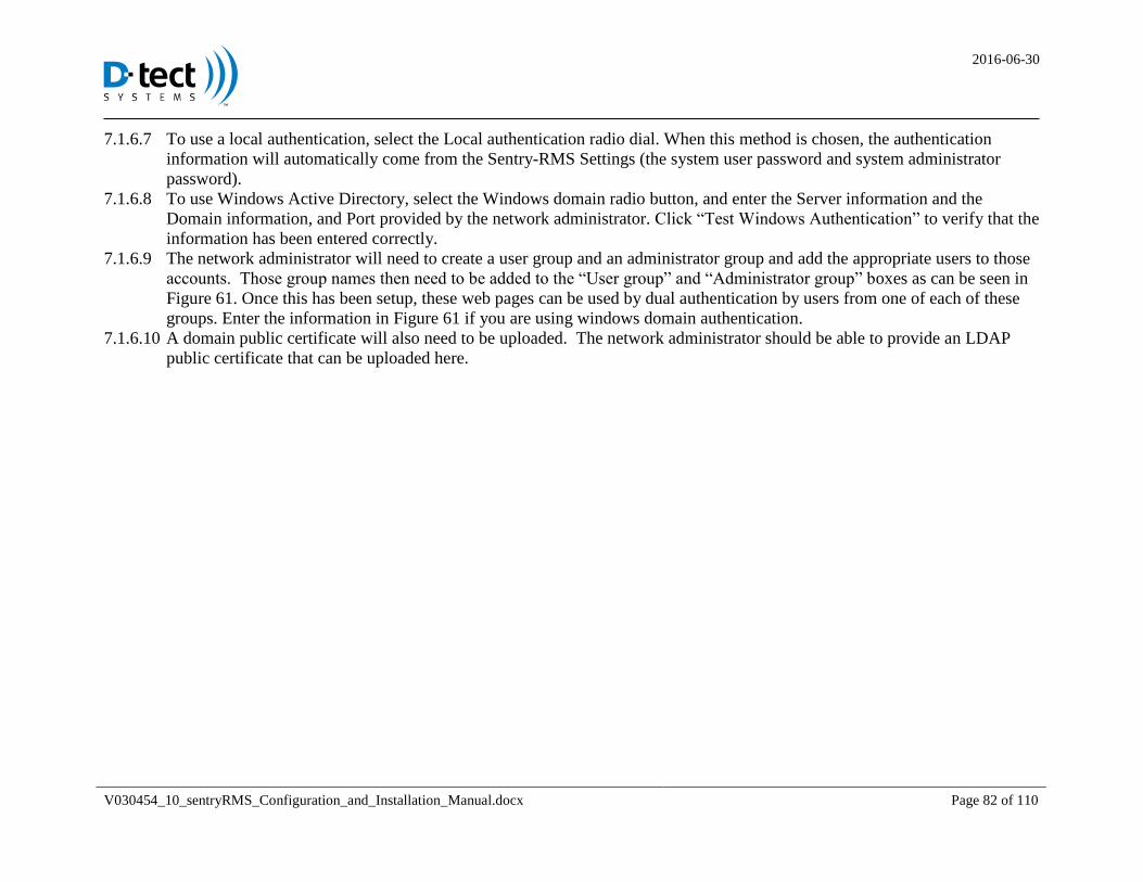
2016-06-30
V030454_10_sentryRMS_Configuration_and_Installation_Manual.docx Page 82 of 110
To use a local authentication, select the Local authentication radio dial. When this method is chosen, the authentication 7.1.6.7
information will automatically come from the Sentry-RMS Settings (the system user password and system administrator
password).
To use Windows Active Directory, select the Windows domain radio button, and enter the Server information and the 7.1.6.8
Domain information, and Port provided by the network administrator. Click “Test Windows Authentication” to verify that the
information has been entered correctly.
The network administrator will need to create a user group and an administrator group and add the appropriate users to those 7.1.6.9
accounts. Those group names then need to be added to the “User group” and “Administrator group” boxes as can be seen in
Figure 61. Once this has been setup, these web pages can be used by dual authentication by users from one of each of these
groups. Enter the information in Figure 61 if you are using windows domain authentication.
A domain public certificate will also need to be uploaded. The network administrator should be able to provide an LDAP 7.1.6.10
public certificate that can be uploaded here.
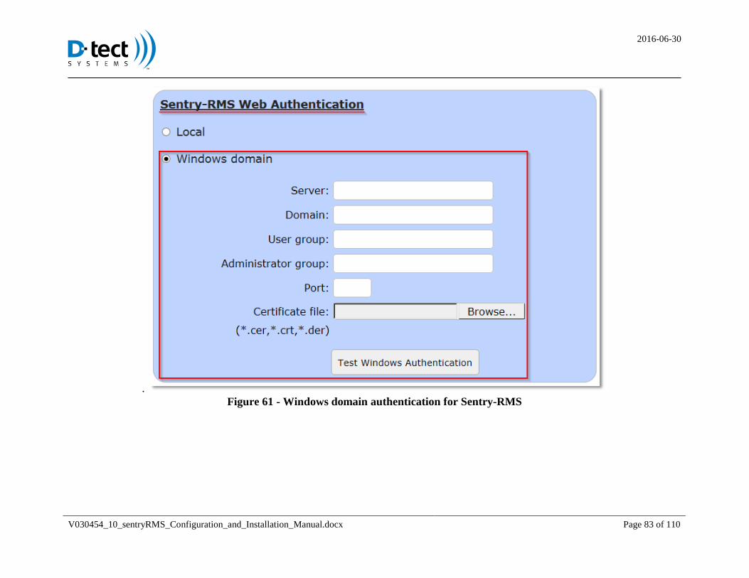
2016-06-30
V030454_10_sentryRMS_Configuration_and_Installation_Manual.docx Page 83 of 110
.
Figure 61 - Windows domain authentication for Sentry-RMS
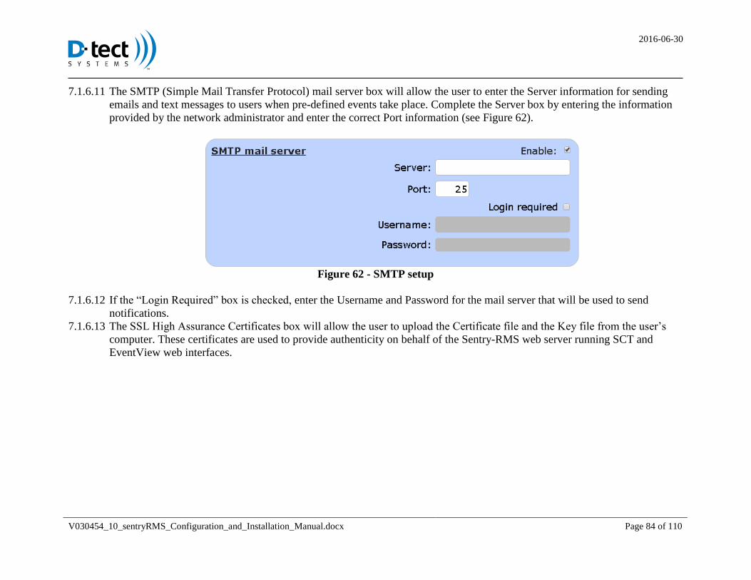
2016-06-30
V030454_10_sentryRMS_Configuration_and_Installation_Manual.docx Page 84 of 110
The SMTP (Simple Mail Transfer Protocol) mail server box will allow the user to enter the Server information for sending 7.1.6.11
emails and text messages to users when pre-defined events take place. Complete the Server box by entering the information
provided by the network administrator and enter the correct Port information (see Figure 62).
Figure 62 - SMTP setup
If the “Login Required” box is checked, enter the Username and Password for the mail server that will be used to send 7.1.6.12
notifications.
The SSL High Assurance Certificates box will allow the user to upload the Certificate file and the Key file from the user’s 7.1.6.13
computer. These certificates are used to provide authenticity on behalf of the Sentry-RMS web server running SCT and
EventView web interfaces.
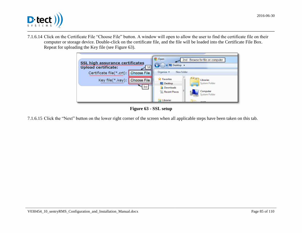
2016-06-30
V030454_10_sentryRMS_Configuration_and_Installation_Manual.docx Page 85 of 110
Click on the Certificate File “Choose File” button. A window will open to allow the user to find the certificate file on their 7.1.6.14
computer or storage device. Double-click on the certificate file, and the file will be loaded into the Certificate File Box.
Repeat for uploading the Key file (see Figure 63).
Figure 63 - SSL setup
Click the “Next” button on the lower right corner of the screen when all applicable steps have been taken on this tab. 7.1.6.15
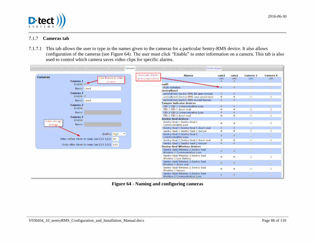
2016-06-30
V030454_10_sentryRMS_Configuration_and_Installation_Manual.docx Page 86 of 110
Cameras tab 7.1.7
This tab allows the user to type in the names given to the cameras for a particular Sentry-RMS device. It also allows 7.1.7.1
configuration of the cameras (see Figure 64). The user must click “Enable” to enter information on a camera. This tab is also
used to control which camera saves video clips for specific alarms.
Figure 64 - Naming and configuring cameras
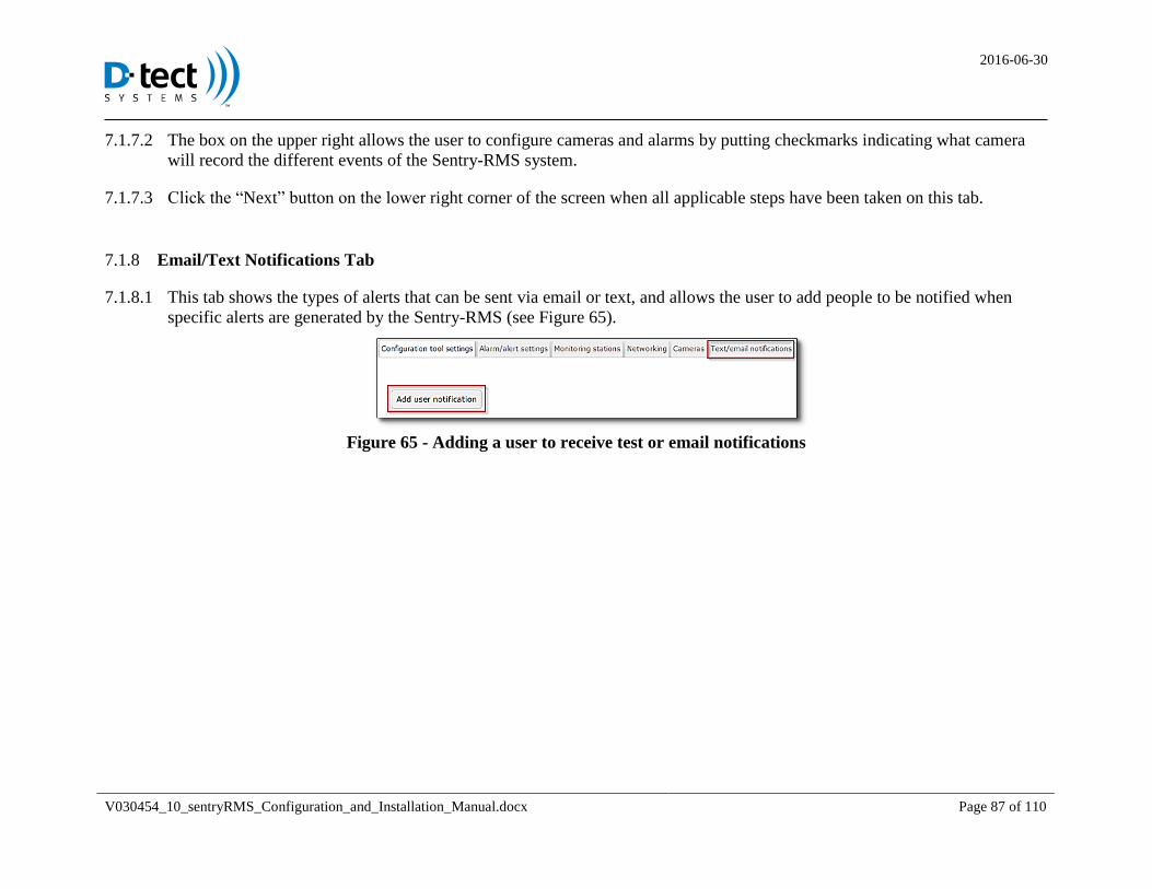
2016-06-30
V030454_10_sentryRMS_Configuration_and_Installation_Manual.docx Page 87 of 110
The box on the upper right allows the user to configure cameras and alarms by putting checkmarks indicating what camera 7.1.7.2
will record the different events of the Sentry-RMS system.
Click the “Next” button on the lower right corner of the screen when all applicable steps have been taken on this tab. 7.1.7.3
Email/Text Notifications Tab 7.1.8
This tab shows the types of alerts that can be sent via email or text, and allows the user to add people to be notified when 7.1.8.1
specific alerts are generated by the Sentry-RMS (see Figure 65).
Figure 65 - Adding a user to receive test or email notifications
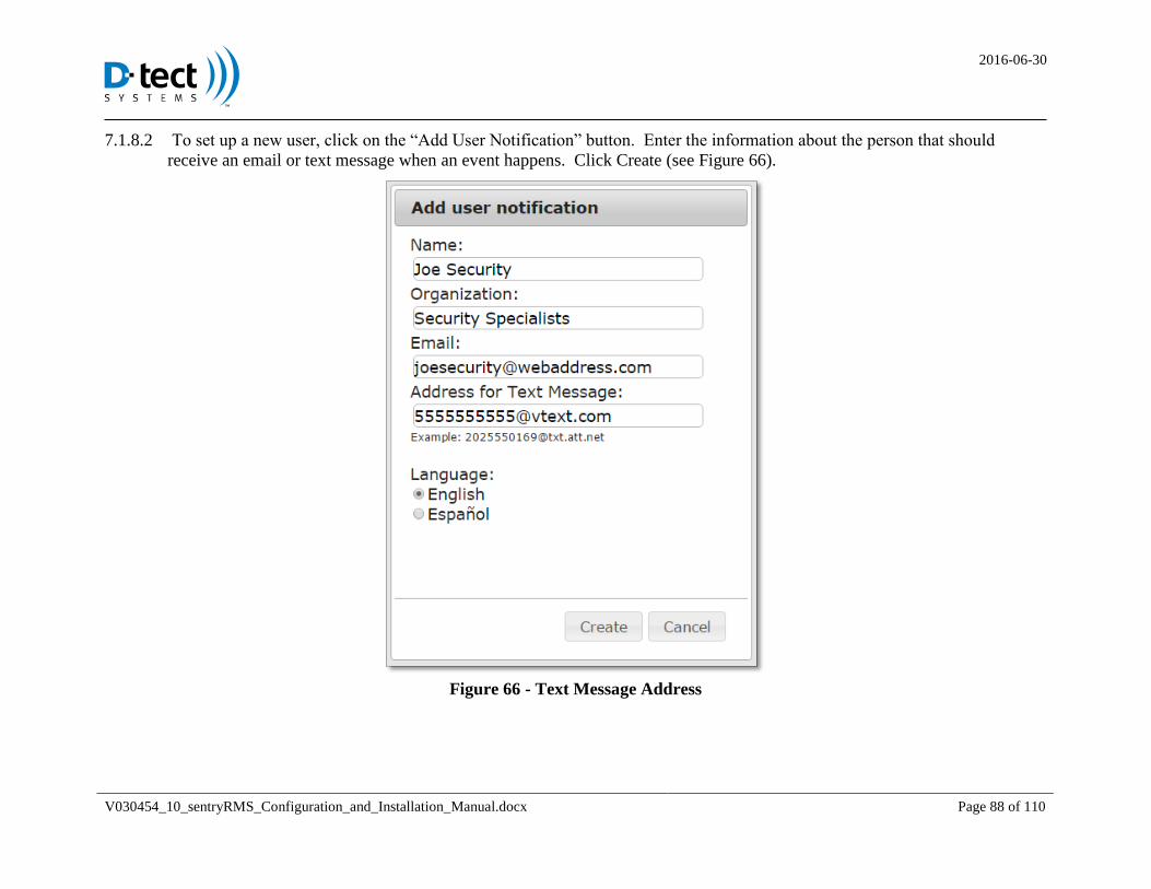
2016-06-30
V030454_10_sentryRMS_Configuration_and_Installation_Manual.docx Page 88 of 110
To set up a new user, click on the “Add User Notification” button. Enter the information about the person that should 7.1.8.2
receive an email or text message when an event happens. Click Create (see Figure 66).
Figure 66 - Text Message Address
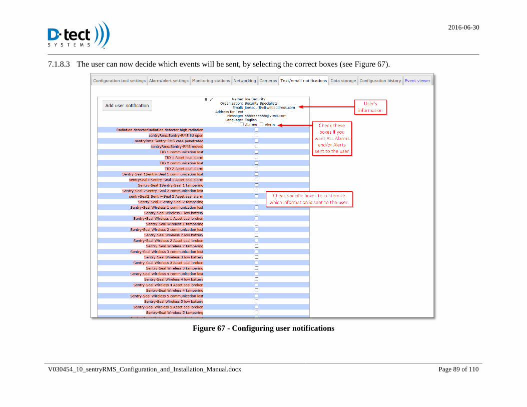
2016-06-30
V030454_10_sentryRMS_Configuration_and_Installation_Manual.docx Page 89 of 110
The user can now decide which events will be sent, by selecting the correct boxes (see Figure 67). 7.1.8.3
Figure 67 - Configuring user notifications
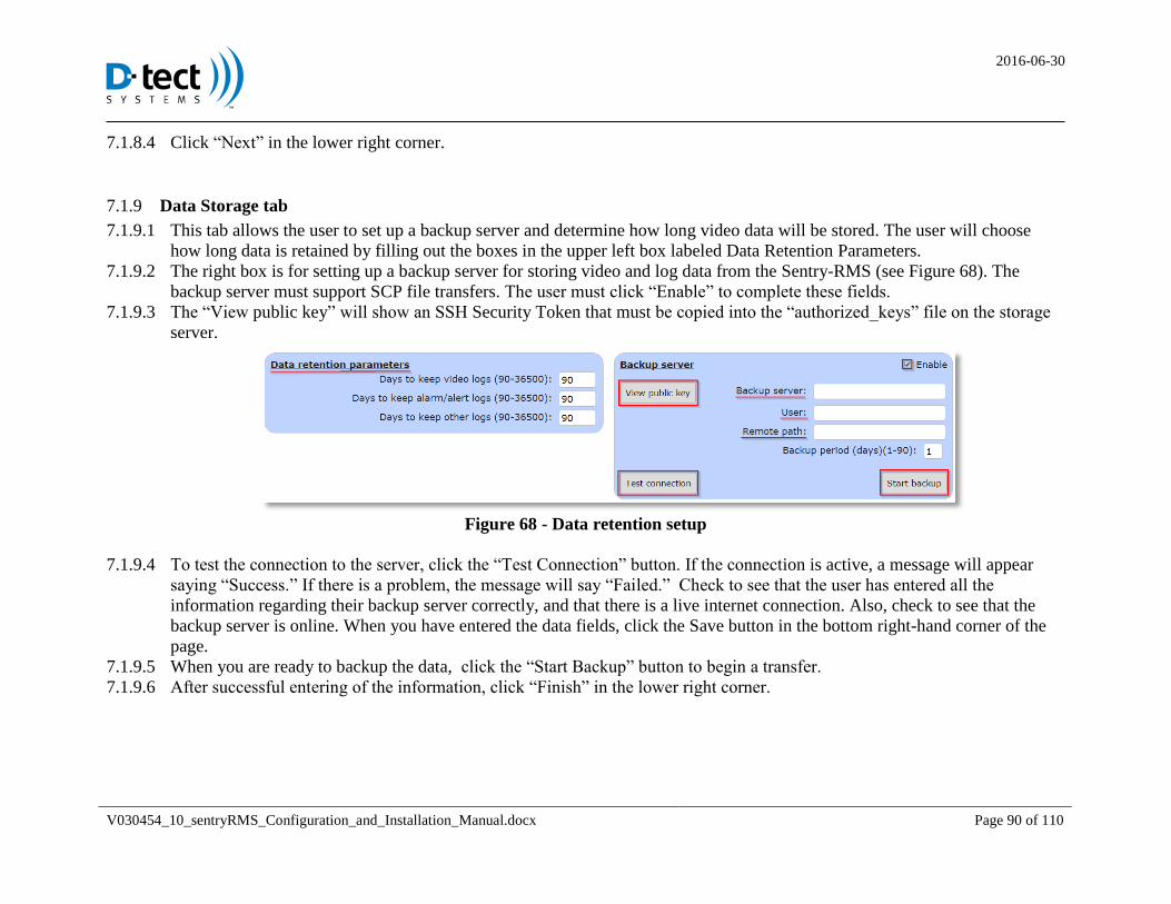
2016-06-30
V030454_10_sentryRMS_Configuration_and_Installation_Manual.docx Page 90 of 110
Click “Next” in the lower right corner. 7.1.8.4
Data Storage tab 7.1.9
This tab allows the user to set up a backup server and determine how long video data will be stored. The user will choose 7.1.9.1
how long data is retained by filling out the boxes in the upper left box labeled Data Retention Parameters.
The right box is for setting up a backup server for storing video and log data from the Sentry-RMS (see Figure 68). The 7.1.9.2
backup server must support SCP file transfers. The user must click “Enable” to complete these fields.
The “View public key” will show an SSH Security Token that must be copied into the “authorized_keys” file on the storage 7.1.9.3
server.
Figure 68 - Data retention setup
To test the connection to the server, click the “Test Connection” button. If the connection is active, a message will appear 7.1.9.4
saying “Success.” If there is a problem, the message will say “Failed.” Check to see that the user has entered all the
information regarding their backup server correctly, and that there is a live internet connection. Also, check to see that the
backup server is online. When you have entered the data fields, click the Save button in the bottom right-hand corner of the
page.
When you are ready to backup the data, click the “Start Backup” button to begin a transfer. 7.1.9.5
After successful entering of the information, click “Finish” in the lower right corner. 7.1.9.6
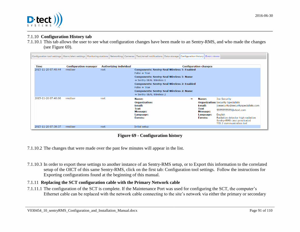
2016-06-30
V030454_10_sentryRMS_Configuration_and_Installation_Manual.docx Page 91 of 110
Configuration History tab 7.1.10 This tab allows the user to see what configuration changes have been made to an Sentry-RMS, and who made the changes 7.1.10.1
(see Figure 69).
Figure 69 - Configuration history
The changes that were made over the past few minutes will appear in the list. 7.1.10.2
In order to export these settings to another instance of an Sentry-RMS setup, or to Export this information to the correlated 7.1.10.3
setup of the OICT of this same Sentry-RMS, click on the first tab: Configuration tool settings. Follow the instructions for
Exporting configurations found at the beginning of this manual.
Replacing the SCT configuration cable with the Primary Network cable 7.1.11
The configuration of the SCT is complete. If the Maintenance Port was used for configuring the SCT, the computer’s 7.1.11.1
Ethernet cable can be replaced with the network cable connecting to the site’s network via either the primary or secondary
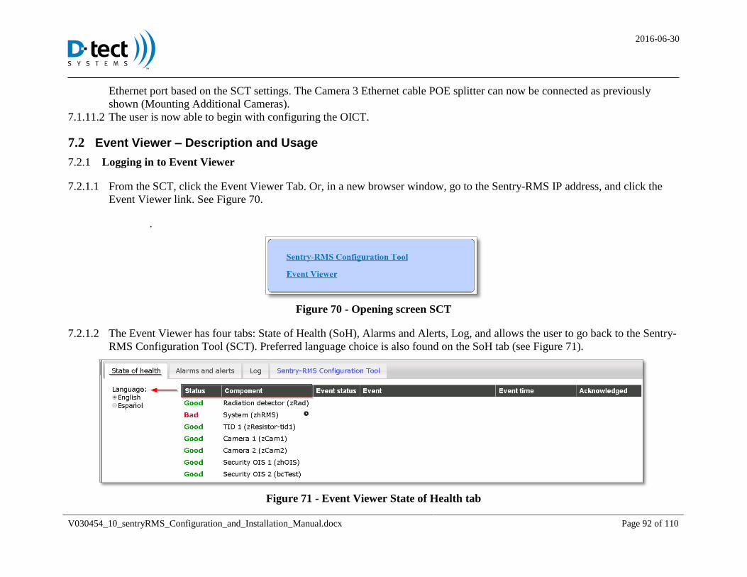
2016-06-30
V030454_10_sentryRMS_Configuration_and_Installation_Manual.docx Page 92 of 110
Ethernet port based on the SCT settings. The Camera 3 Ethernet cable POE splitter can now be connected as previously
shown (Mounting Additional Cameras).
The user is now able to begin with configuring the OICT. 7.1.11.2
7.2 Event Viewer – Description and Usage
Logging in to Event Viewer 7.2.1
From the SCT, click the Event Viewer Tab. Or, in a new browser window, go to the Sentry-RMS IP address, and click the 7.2.1.1
Event Viewer link. See Figure 70.
.
Figure 70 - Opening screen SCT
The Event Viewer has four tabs: State of Health (SoH), Alarms and Alerts, Log, and allows the user to go back to the Sentry-7.2.1.2
RMS Configuration Tool (SCT). Preferred language choice is also found on the SoH tab (see Figure 71).
Figure 71 - Event Viewer State of Health tab
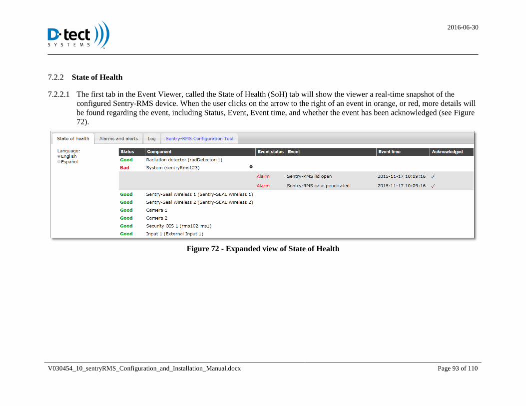
2016-06-30
V030454_10_sentryRMS_Configuration_and_Installation_Manual.docx Page 93 of 110
State of Health 7.2.2
The first tab in the Event Viewer, called the State of Health (SoH) tab will show the viewer a real-time snapshot of the 7.2.2.1
configured Sentry-RMS device. When the user clicks on the arrow to the right of an event in orange, or red, more details will
be found regarding the event, including Status, Event, Event time, and whether the event has been acknowledged (see Figure
72).
Figure 72 - Expanded view of State of Health
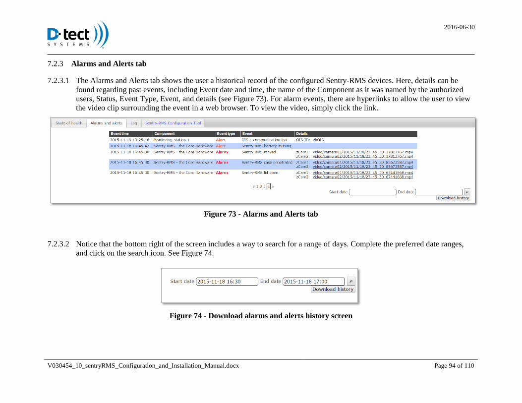
2016-06-30
V030454_10_sentryRMS_Configuration_and_Installation_Manual.docx Page 94 of 110
Alarms and Alerts tab 7.2.3
The Alarms and Alerts tab shows the user a historical record of the configured Sentry-RMS devices. Here, details can be 7.2.3.1
found regarding past events, including Event date and time, the name of the Component as it was named by the authorized
users, Status, Event Type, Event, and details (see Figure 73). For alarm events, there are hyperlinks to allow the user to view
the video clip surrounding the event in a web browser. To view the video, simply click the link.
Figure 73 - Alarms and Alerts tab
Notice that the bottom right of the screen includes a way to search for a range of days. Complete the preferred date ranges, 7.2.3.2
and click on the search icon. See Figure 74.
Figure 74 - Download alarms and alerts history screen
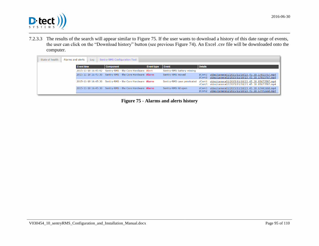
2016-06-30
V030454_10_sentryRMS_Configuration_and_Installation_Manual.docx Page 95 of 110
The results of the search will appear similar to Figure 75. If the user wants to download a history of this date range of events, 7.2.3.3
the user can click on the “Download history” button (see previous Figure 74). An Excel .csv file will be downloaded onto the
computer.
Figure 75 - Alarms and alerts history
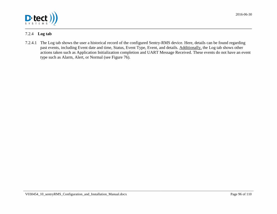
2016-06-30
V030454_10_sentryRMS_Configuration_and_Installation_Manual.docx Page 96 of 110
Log tab 7.2.4
The Log tab shows the user a historical record of the configured Sentry-RMS device. Here, details can be found regarding 7.2.4.1
past events, including Event date and time, Status, Event Type, Event, and details. Additionally, the Log tab shows other
actions taken such as Application Initialization completion and UART Message Received. These events do not have an event
type such as Alarm, Alert, or Normal (see Figure 76).
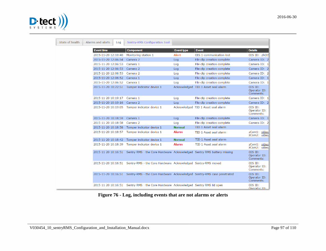
2016-06-30
V030454_10_sentryRMS_Configuration_and_Installation_Manual.docx Page 97 of 110
Figure 76 - Log, including events that are not alarms or alerts
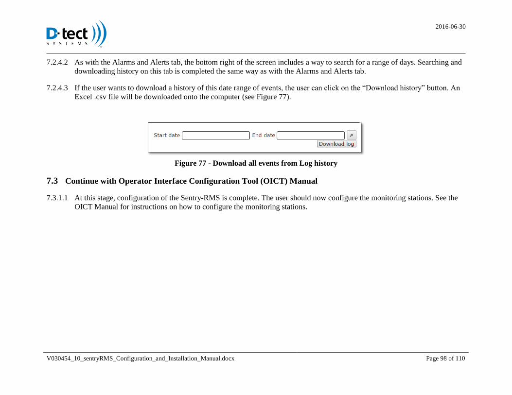
2016-06-30
V030454_10_sentryRMS_Configuration_and_Installation_Manual.docx Page 98 of 110
As with the Alarms and Alerts tab, the bottom right of the screen includes a way to search for a range of days. Searching and 7.2.4.2
downloading history on this tab is completed the same way as with the Alarms and Alerts tab.
If the user wants to download a history of this date range of events, the user can click on the “Download history” button. An 7.2.4.3
Excel .csv file will be downloaded onto the computer (see Figure 77).
Figure 77 - Download all events from Log history
7.3 Continue with Operator Interface Configuration Tool (OICT) Manual
At this stage, configuration of the Sentry-RMS is complete. The user should now configure the monitoring stations. See the 7.3.1.1
OICT Manual for instructions on how to configure the monitoring stations.

2016-06-30
V030454_10_sentryRMS_Configuration_and_Installation_Manual.docx Page 99 of 110
8 Technical Specifications
8.1 Electrical Requirements
120 VAC, 60Hz, 2 A
8.2 Water ingress protection rating
NEMA 4: provide a degree of protection against dust, water droplets, and splashing water
8.3 Storage Temperature
The Sentry-RMS storage and shipping temperature range is -45° F to +145° F. The backup battery must be removed during storage
and shipping.
8.4 Operating Temperature
The Sentry-RMS operating temperature range is 20° F to 120° F.
8.5 Atmospheric Pressure (Altitude)
The Sentry-RMS is intended for operation up to 2,000 meters above sea level.
8.6 Humidity
The Sentry-RMS can operate in an environment of 20 to 85 percent relative humidity, non-condensing, throughout its life.
9 Maintenance & Servicing
The Sentry-RMS contains self-monitors to determine if the equipment is functioning correctly. Refer to State of Health tab in
software. The Sentry-RMS is intended only for indoor use.
Authorized Service Personnel must disconnect power using wall circuit breaker prior to performing any service or repair on
this equipment.
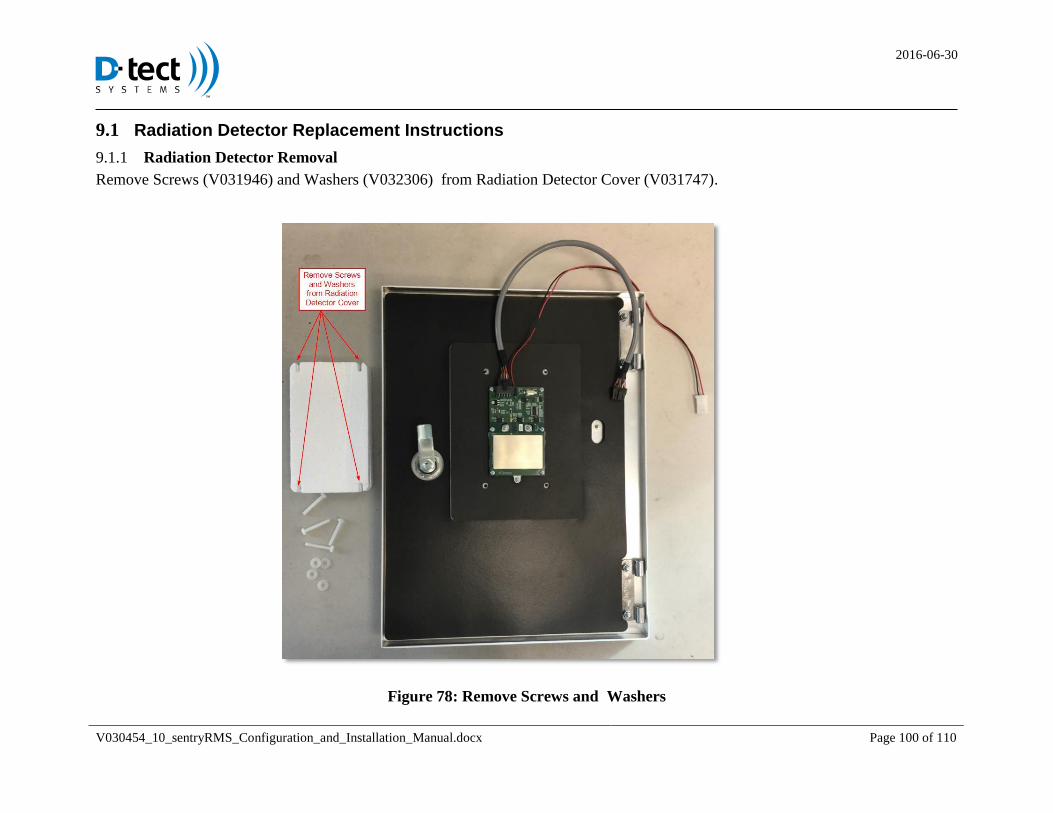
2016-06-30
V030454_10_sentryRMS_Configuration_and_Installation_Manual.docx Page 100 of 110
9.1 Radiation Detector Replacement Instructions
Radiation Detector Removal 9.1.1
Remove Screws (V031946) and Washers (V032306) from Radiation Detector Cover (V031747).
Figure 78: Remove Screws and Washers
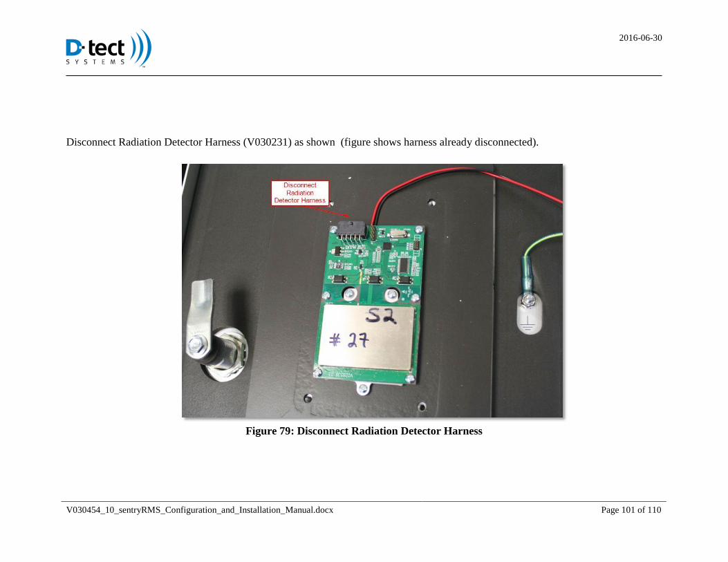
2016-06-30
V030454_10_sentryRMS_Configuration_and_Installation_Manual.docx Page 101 of 110
Disconnect Radiation Detector Harness (V030231) as shown (figure shows harness already disconnected).
Figure 79: Disconnect Radiation Detector Harness

2016-06-30
V030454_10_sentryRMS_Configuration_and_Installation_Manual.docx Page 102 of 110
Remove Six Screws (V030152) from Radiation Detector PCBA (V028535) as shown in Figure 80 (figure shows screws already
removed).
Figure 80: Remove Six Screws

2016-06-30
V030454_10_sentryRMS_Configuration_and_Installation_Manual.docx Page 103 of 110
The figure below shows Radiation Detector PCBA (V028535) removed. Make sure to leave thermal gap pad attached.
Figure 81: Radiation Detector PCBA Removed

2016-06-30
V030454_10_sentryRMS_Configuration_and_Installation_Manual.docx Page 104 of 110
Radiation Detector Cover Installation 9.1.2
Attach Radiation Detector PCBA Board (V028535), Routing wire between the two top standoffs and Tighten Screws (V030152) to
0.16 N*m (1.4 in*lb).
Figure 82: Radiation Detector Installed onto Hot Plate
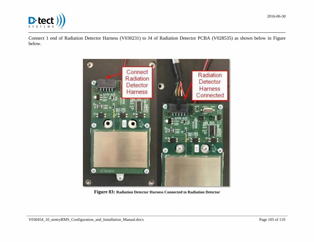
2016-06-30
V030454_10_sentryRMS_Configuration_and_Installation_Manual.docx Page 105 of 110
Connect 1 end of Radiation Detector Harness (V030231) to J4 of Radiation Detector PCBA (V028535) as shown below in Figure
below.
Figure 83: Radiation Detector Harness Connected to Radiation Detector
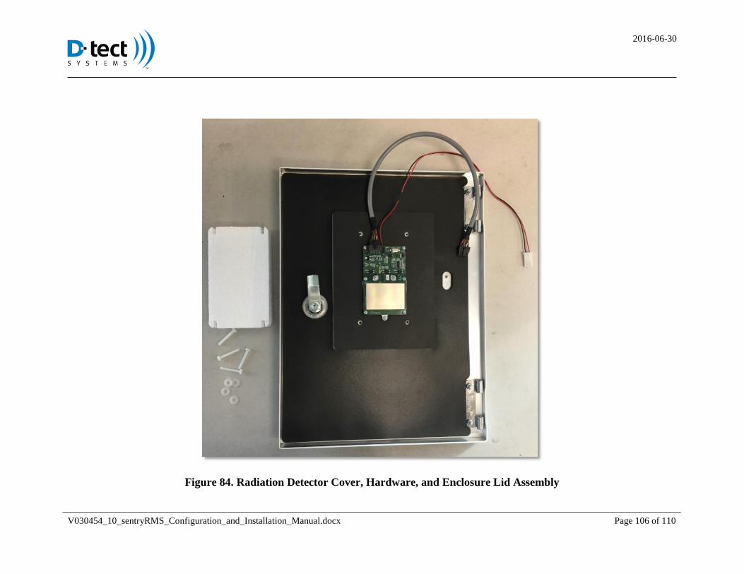
2016-06-30
V030454_10_sentryRMS_Configuration_and_Installation_Manual.docx Page 106 of 110
Figure 84. Radiation Detector Cover, Hardware, and Enclosure Lid Assembly
2016-06-30
V030454_10_sentryRMS_Configuration_and_Installation_Manual.docx Page 107 of 110
Place Radiation Detector Cover (V031747) over Radiation Detector PCBA (V028535), with Radiation Detector Harness (V030231)
and TEC Harness (V030711) exiting through the notch in Radiation Detector Cover (V031747).
Secure Radiation Detector Cover (V031747) with Washers (V032306) and Screws (V031946) as shown below in Figure 85. Take care
not to overtighten Screws (V031946).
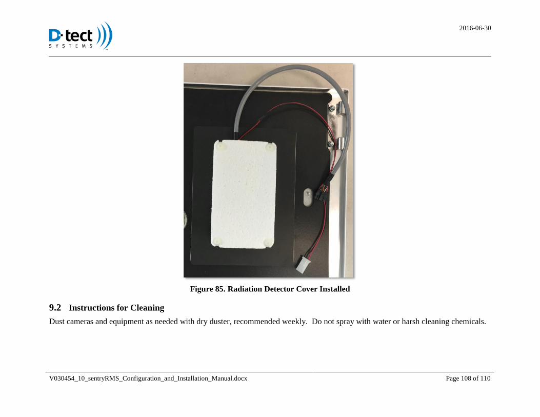
2016-06-30
V030454_10_sentryRMS_Configuration_and_Installation_Manual.docx Page 108 of 110
Figure 85. Radiation Detector Cover Installed
9.2 Instructions for Cleaning
Dust cameras and equipment as needed with dry duster, recommended weekly. Do not spray with water or harsh cleaning chemicals.
2016-06-30
V030454_10_sentryRMS_Configuration_and_Installation_Manual.docx Page 109 of 110
9.3 Service and Repair
In order to guarantee safe operation and proper functionality, all servicing and repair must be performed by the manufacturer.
Replacement of batteries and fuses may be performed by D-tect Systems authorized service personnel or traineded 3rd
party
installer/electrician. If equipment is used in a manner not specified by the manufacturer, the protection provided by the equipment may
be impaired.
9.4 Contact Information
SentryRMS warranty support from D-tect Systems can be received by phone at 801-260-4075 or email at
[email protected]. D-tect will respond to email or voice messages within 24 hours, 365 days a year.
NOTE: Please contact D-tect Systems for approval prior to shipping. Ship to:
D-tect Systems
313 W. 12800 South, Suite 311
Draper, UT 84020
9.5 Warranty
D-tect Systems will provide a three-year warranty to PNNL from the date of shipment from the PNNL warehouse.
9.6 Replacement Battery
The sealed lead acid battery should only be replaced by a CSB Battery Technologies part number HR1251WF2FR. When end of
useful battery life is achieved, recycle battery at approved local recycling facility.
9.7 Replacement Fuses Specifications
Fuse Located in Terminal Block
Littlefuse 0312003.HXP 3A 250VAC
Fuse located on main board PCB:
Littlefuse 0297015.WXNV FUSE AUTO 15A 32VDC BLADE MINI
2016-06-30
V030454_10_sentryRMS_Configuration_and_Installation_Manual.docx Page 110 of 110
9.8 Sentry-RMS Open Ports
Listed below are the open ports of the Sentry-RMS. Note that OIS monitors do not communicate across standard NAT devices without
a VPN.
OIS Monitor:
o Internet Key Exchange (IKE) – UDP port 500
o Encapsulating Security Payload (ESP) – IP protocol 50
RMS Site Inbound
o CHCT:
HTTP – TCP port 80
HTTPS – TCP port 443
o Other:
SSH – TCP port 22 (optional – only for maintenance use outside the normal web configuration tools)
RMS Site Outbound
o SMTP: (optional – only if configured for email notifications) default UDP and TCP port 25 (this port depends on their
configuration)
o LDAP (optional – only if configured for Windows Domain authentication): default TCP port 389 (this port depends on
their configuration)
o RSYNC (optional – only if configured for data backups)
TCP port 873
o NTP, time synchronization (optional, time will also be synchronized from Monitoring stations)
UDP port 123
9.9 Radiation Detection Procedure
If unsafe radiation levels are detected, follow your company policies concerning procedures and contact appropriate individuals.