vacuum technology - iuac, new delhi · conductance conductance is the ratio of throughput, under...
TRANSCRIPT

Vacuum Technology
Rajeev Mehta
Part – 1: Basics

What is Vacuum ? What’s the need ?

Lets first see Pressure........
Molecules moves in straight path
Hit other molecule or wall of container
Imposes force on wall This force per unit area
is PRESSURE
P = F/A
Pressure due to 1 N on 1 m2 area is 1 Pa
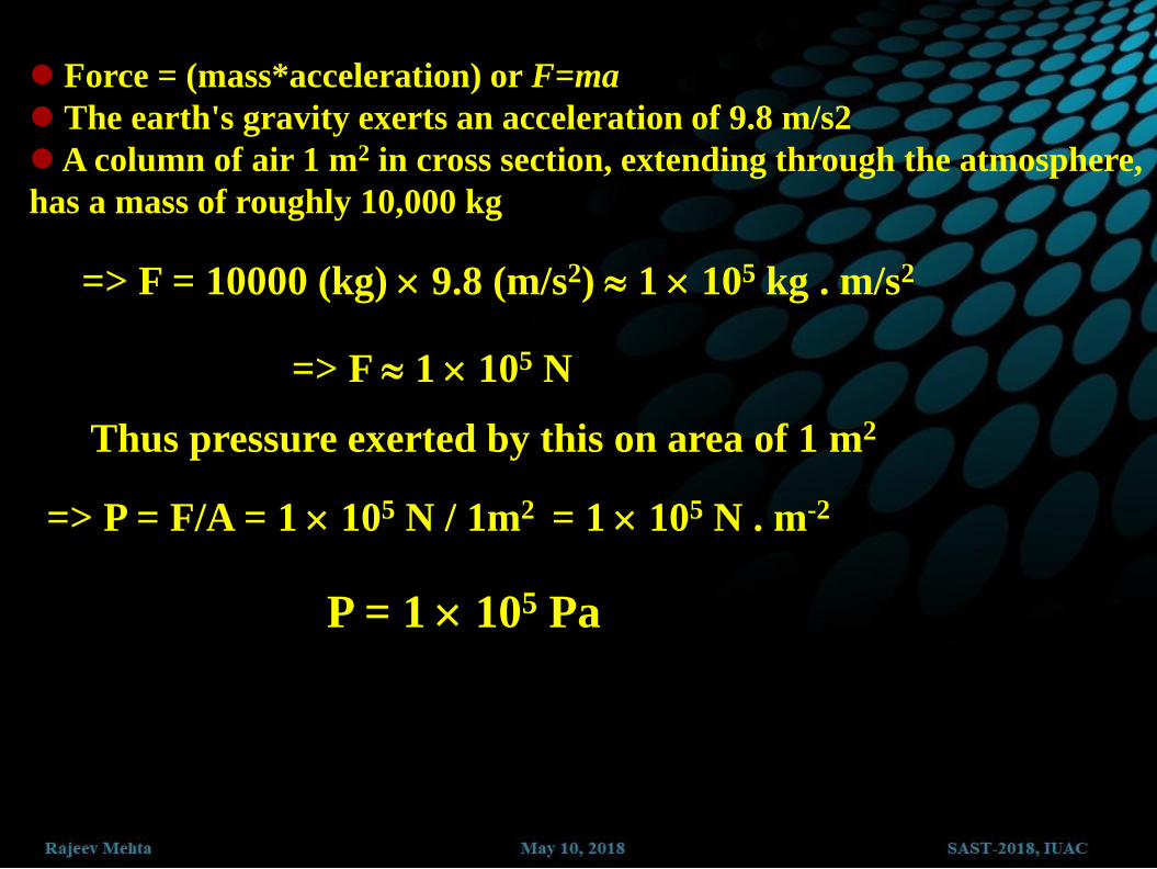
Force = (mass*acceleration) or F=ma
The earth's gravity exerts an acceleration of 9.8 m/s2
A column of air 1 m2 in cross section, extending through the atmosphere,
has a mass of roughly 10,000 kg
=> F = 10000 (kg) 9.8 (m/s2) 1 105 kg . m/s2
=> F 1 105 N
Thus pressure exerted by this on area of 1 m2
=> P = F/A = 1 105 N / 1m2 = 1 105 N . m-2
P = 1 105 Pa

Fluid Pressure
Pressure is due to fluid weight above it
P = gh P = P
a±gh
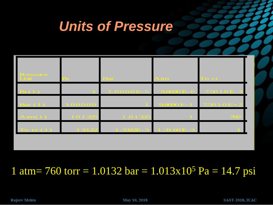
Units of Pressure
Pa Bar Atm To rr
Pa (1) 1 1.0000E-5 9.8690E-6 7.5010E-3
Bar (1) 100000 1 9.8690E-1 7.5010E+2
Atm (1) 101325 1.01325 1 760
To rr (1) 133.22 1.3322E-3 1.3160E-3 1
Pressure Unit
1 atm= 760 torr = 1.0132 bar = 1.013x10⁵ Pa = 14.7 psi
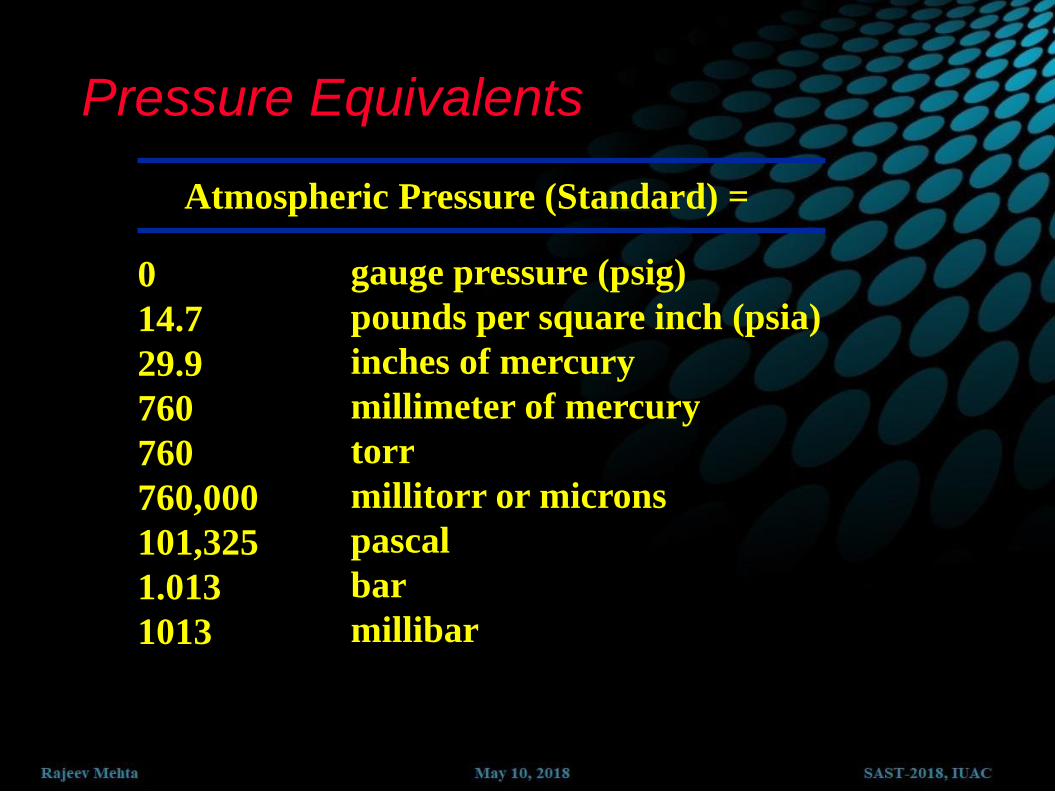
Pressure Equivalents
0
14.7
29.9
760
760
760,000
101,325
1.013
1013
gauge pressure (psig)
pounds per square inch (psia)
inches of mercury
millimeter of mercury
torr
millitorr or microns
pascal
bar
millibar
Atmospheric Pressure (Standard) =

THE ATMOSPHERE IS A MIXTURE OF GASES
PARTIAL PRESSURES OF GASES CORRESPOND TO THEIR RELATIVE VOLUMES
GAS SYMBOL PERCENT BY
VOLUME
PARTIAL PRESSURE
TORR PASCAL
Nitrogen
Oxygen
Argon
Carbon Dioxide
Neon
Helium
Krypton
Hydrogen
Xenon
Water
N2
O2
A
CO2
Ne
He
Kr
H2
X
H2O
78
21
0.93
0.03
0.0018
0.0005
0.0001
0.00005
0.0000087
Variable
593
158
7.1
0.25
1.4 x 10⁻²
4.0 x 10⁻³
8.7 x 10⁻⁴
4.0 x 10⁻⁴
6.6 x 10⁻⁵
5 to 50
79,000
21,000
940
33
1.8
5.3 x 10⁻¹
1.1 x 10⁻¹
5.1 x 10⁻²
8.7 x 10⁻³
665 to 6650

After Pressure............Vacuum
Latin word VACUUS => Empty Pressure above sea level....... @ Sea Level => P ~ 101325 Pa h ~ 10000 m => P ~ 26500 Pa h ~ 161 km => P ~ 0.0007 Pa

Why is a Vacuum Needed?
To move a particle in a (straight) line over a large distance

Why is a Vacuum Needed?
Contamination
(usually water)
Atmosphere
Clean surface
(High)Vacuum
To provide a clean surface

Few Basics.......................
Ideal Gas Law ... pV = n RT N
A = 6.022 X 10²³ /mole
R = 83.14 mbar L/Kelvin mole k = R/N
A = 1.380650 X 10⁻²³ J/K
p
n = 101325 Pa, T
n = 273 K, V
n = 22.414 L
1 mole of particles (6.022 X 10²³) occupy
22.414 L @ pn & T
n In 1 L @ 1 mbar & 293 K there are 2.478 X 10¹⁹
particles
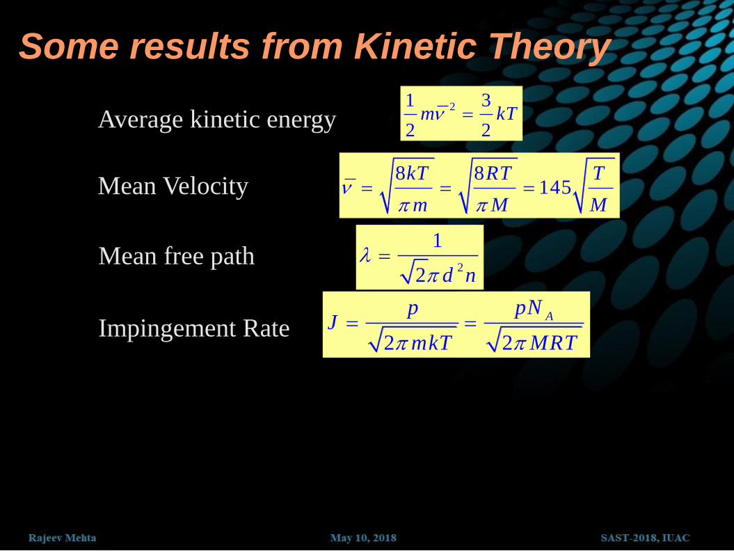
Some results from Kinetic Theory
Average kinetic energy 21 3
2 2m kT
8 8145
kT RT T
m M M
2
1
2 d n
Impingement Rate
Mean Velocity
Mean free path
2 2
ApNp
JmkT MRT

Mean Free Path
• Mean free path of a particle, is the average distance the particle travels between collisions with other particles.
• The magnitude of mean free path depends on the
characteristics of the system the particle is in:
diameter molecule d
eunit volumper particles of no.η
area sectional cross effective
Path FreeMean
constant22
12
where
pp
kT
d

Vacuum Range Pressure # of Molecules MFP
Ambient 1000 mbar 2.7 X 10¹⁹ 68 nm
Low Vacuum 300 - 1 mbar 1019 - 1016 .1 – 100 m
Medium Vacuum 1 – 10-3 mbar 1016 - 1013 .1 – 100 mm
High Vacuum 10-3 -10-7 mbar 1013 - 109 10 cm – 1 km
UH Vacuum 10-7 -10-12 mbar 109 - 104 1 km – 105 km

Mean free path is important parameter for
vacuum system
If MFP < vacuum system dimensions then flow
is viscous flow, molecules are transported as bulk parcel
If MFP > vacuum system dimensions then flow is molecular flow, molecules are transported individually through diffusion

Viscous and Molecular Flow
Viscous Flow
(momentum transfer
between molecules)
Molecular Flow
(molecules move
independently)

d
λk
na) Nature of gas “Knudsen’s Number”
Gases flowing in a pipes are characterized by
Relative quantity of gas “Reynold’s Number”
dR
Where
= Mean Free Path
d = pipe diameter,
= gas viscosity
= mass density
v = flow velocity

FLOW REGIMES
FLOW
Viscous Kn < 0.01
High Pressure
<<d
Molecular Kn > 1
Low Pressure
> >d
Laminar R < 1200
Stream flow
Turbulent R > 2200
Chaotic flow

FLOW REGIMES
Viscous Flow:
Distance between molecules is small; collisions between
molecules dominate; flow through momentum transfer;
generally P greater than 0.1 mbar
Transition Flow:
Region between viscous and molecular flow
Molecular Flow:
Distance between molecules is large; collisions between
molecules and wall dominate; flow through random motion;
generally P smaller than 10-3 mbar

FLOW REGIMES Mean Free Path
Characteristic Dimension Viscous Flow: is less than 0.01
Mean Free Path
Characteristic Dimension Molecular Flow: is greater than 1
Mean Free Path
Characteristic Dimension Transition Flow: is between 0.01 and 1

Part – 3: Terminologies
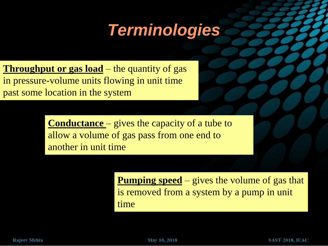
Terminologies
Throughput or gas load – the quantity of gas
in pressure-volume units flowing in unit time
past some location in the system
Pumping speed – gives the volume of gas that
is removed from a system by a pump in unit
time
Conductance – gives the capacity of a tube to
allow a volume of gas pass from one end to
another in unit time

THROUGHPUT & GAS LOAD
Throughput and gas load can be defined as the
quantity of gas in pressure-volume units
flowing in unit time past some location in the
system.
Units: (torr x liters / sec) or (Pa x m3 / sec).
Gas in = gas out
or
Gas load = throughput
)( pVdt
dQ

PUMPING SPEED
Pumping speed is defined as the ratio of the
throughput of a given gas to the partial
pressure of that gas at a specific point near the
inlet port of the pump.
Less formally, it is the volume of gas (at any
pressure) that is removed from the system by
the pump in unit time.
Pumping speed is a measure of the pump's
capacity to remove gas from the chamber.
Units: liters per second (L/sec) or (m3/sec).

CONDUCTANCE Conductance is the ratio of throughput, under steady-
state conservation conditions, to the pressure
differential between two specified isobaric sections
inside the pumping system.
Informally, the conductance of a tube is its capacity to let
a volume of gas (at any pressure) pass from one end to
the other in a unit of time.
Conductance is a property of a passive (non-pumping)
component of a vacuum system, similarly as pumping
speed is a property of a pump.
Units: liters per second (L/sec) or (m3/sec).

Consider gas flowing
through the conductance, C.
The quantity of gas entering
in unit time must be the same
as that leaving.
Upstream, this mass occupies
a volume V1 and downstream
V2
So P1V1 = P2V2
Volumetric flow rate is
Throughput is
P1>P2
V
t
VQ P
t

Pumping speed is volumetric rate at which gas is
transported across a plane
inletP
QS
)( pVdt
dQ
dt
dVS
dt
dVP
inlet
SPinlet
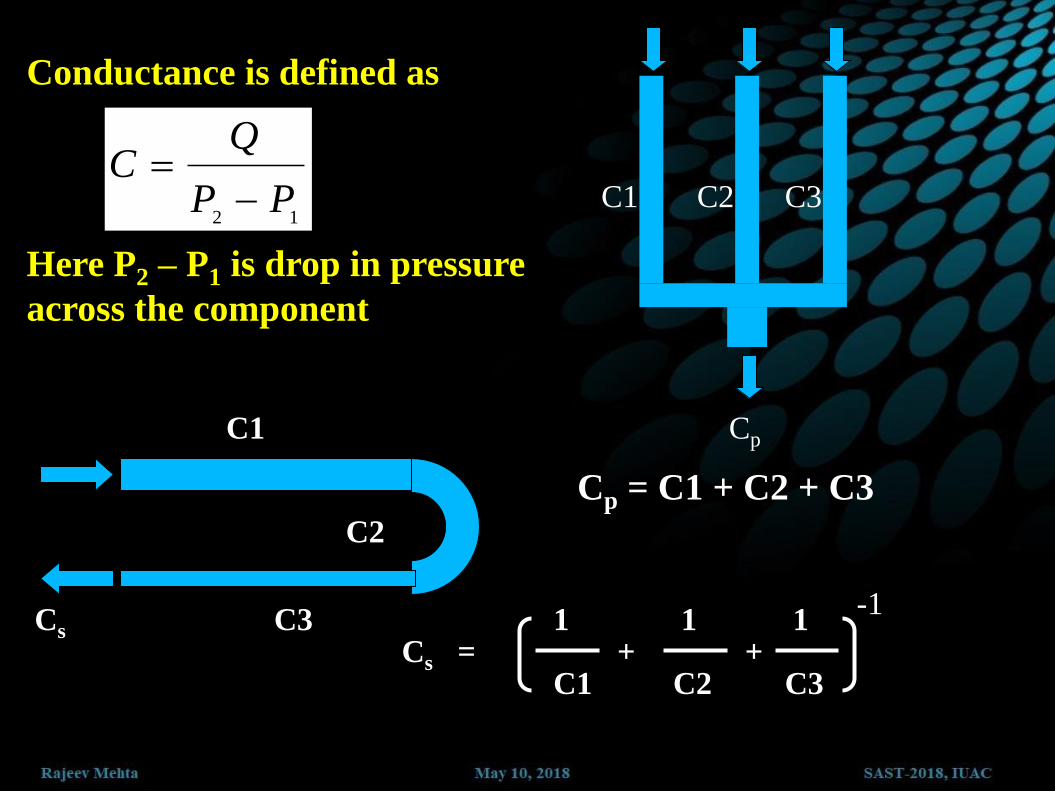
Conductance is defined as
12PP
QC
Here P2 – P1 is drop in pressure
across the component
C1 C2 C3
Cp
Cp = C1 + C2 + C3
C1
C2
C3 Cs
Cs = 1
C1
1
C2
1
C3 + +
-1
For elements of a system connected in series,
we must add the conductance of these elements
as in an electrical circuit: 1/C = 1/C1 + 1/C2 +
1/C3 +…
For elements of a system connected in parallel,
we must add the conductance of these elements
as in an electrical circuit: C = C1 + C2 + C3 +…
Conductance depends on pressure in the low to
medium vacuum regions, and is independent of
pressure in high to ultrahigh vacuum regions.

Flow through cylindrical tube

In the viscous flow regime, the conductance is geometry,
pressure, and viscosity dependent.
here D & L are in meters, P is in Torr,
and η is in poise.
where D is tube diameter & L is length both
in meters, Pav is in Pa, and η is in Pa-sec.
Also if D & L are in cm, P is in Torr,
then η is in micropoise.
avP
l
4D32716Cs
l(
)
avP
l
4DC(
128)
3
sm

In the molecular flow regime, the conductance of a long
cylindrical pipe is given as
l
3DCM
TB
k
s
m
2
6
13
where D is tube diameter &
L is length both in meters,
M in Kg & T in K
Using M (air) = 28.97
Kg/KMole, T as 293K we
get
l
3DC
l
3DC
121120
12.1213
s
l
s
m
or
l
3DCM
Ts
l 81.3
here D & L both in cm, M
in AMU & T in K
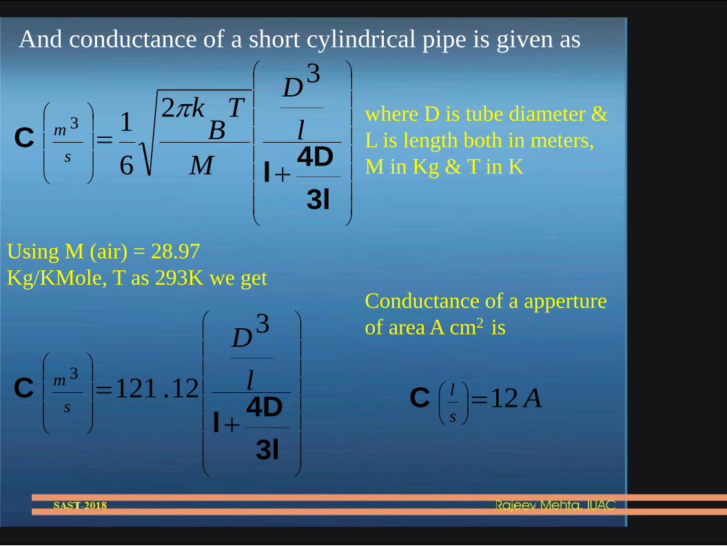
And conductance of a short cylindrical pipe is given as
3l
4Dl
C l
D
M
TB
k
s
m
3
2
6
13 where D is tube diameter &
L is length both in meters,
M in Kg & T in K
Using M (air) = 28.97
Kg/KMole, T as 293K we get
3l
4Dl
C l
D
s
m
3
12.1213
As
l 12
C
Conductance of a apperture
of area A cm2 is

Pumping Speed
2P
QS
p
CPPQ )(21
1P
QS
eff
2P
QS
p
21
21)(
PC
QP
CPPQ
CSSPeff
111

Part – 2: How to Create it?

How to Create VACUUM...
Principle Used: Bernoulli’s
Principle (moving fluid reduces
pressure)
Operation is based on bulk flow
of fluids (viscous flow)
Ultimate vacuum is
approximately 24 Torr (vapor
pressure of water at 25°C)
P1, V1
P2, V2
ATM
V1 < V2, P1 >
P2
Types
1. Mechanical
2. Diffusion
3. Containment
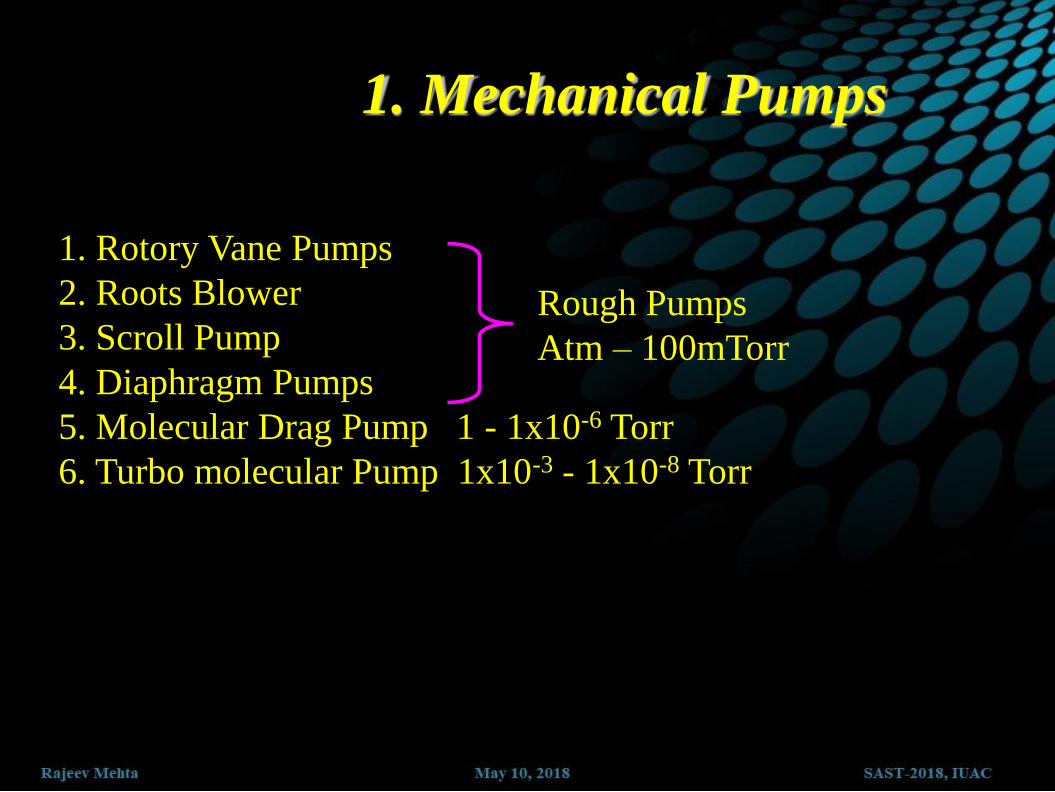
1. Rotory Vane Pumps
2. Roots Blower
3. Scroll Pump
4. Diaphragm Pumps
5. Molecular Drag Pump 1 - 1x10⁻⁶ Torr
6. Turbo molecular Pump 1x10⁻³ - 1x10⁻⁸ Torr
1. Mechanical Pumps
Rough Pumps
Atm – 100mTorr

VACUUM PUMPING METHODS VACUUM PUMPS
(METHODS)
Gas Transfer
Vacuum Pump
Entrapment
Vacuum Pump
Reciprocating
Displacement Pump
Rotary
Pump
Diaphragm
Pump
Piston
Pump
Rotary
Piston Pump
Roots
Pump
Dry
Pump
Fluid Entrainment
Pump
Drag
Pump
Ion Transfer
Pump
Molecular
Drag Pump
Turbomolecular
Pump
Gaseous
Ring Pump
Turbine
Pump
Ejector
Pump
Diffusion
Pump
Adsorption
Pump
Cryopump
Getter
Pump
Getter Ion
Pump
Sputter Ion
Pump
Evaporation
Ion Pump
Bulk Getter
Pump
Cold Trap
Sublimation
Pump
Positive Displacement
Vacuum Pump
Kinetic
Vacuum Pump

Low Vacuum Pump
• Principle of operation :
(1) begin expansion cycle
(2) seal off expanded volume
(3) compress gas out exhaust
• Pump operation is based on bulk
flow of gas ; hence the pump works
in the viscous flow regime
• Used for obtaining "rough" vacuum
(10-3 Torr), which is the lower limit
of the viscous flow regime
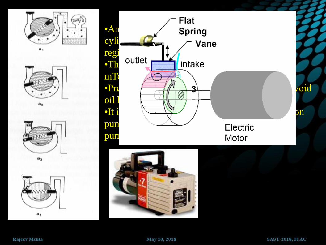
•An oil seal between a phenolic vane and a steel
cylinder is used to remove gas from the vacuum
region and exhaust it to the atmosphere.
•This pump works from atmosphere to about 0.1
mTorr.
•Precautions must be taken at low pressures to avoid
oil back streaming into the vacuum vessel.
•It is also used as a backing pump for compression
pumps like a diffusion pump or turbo molecular
pump


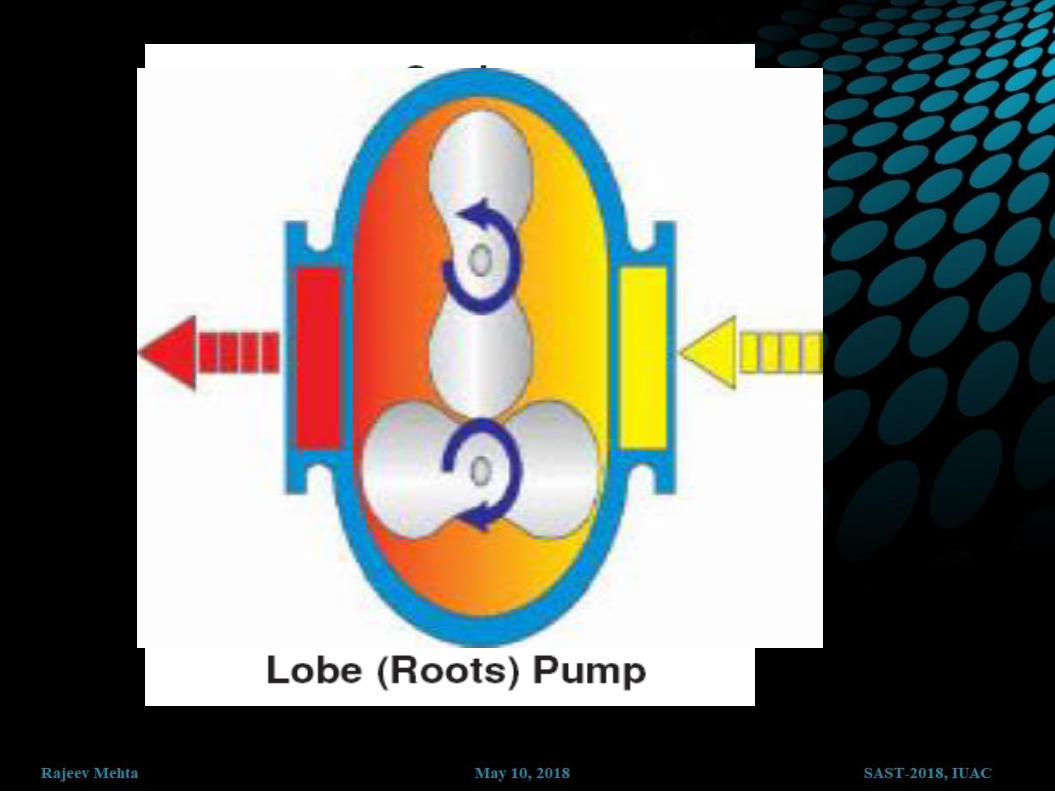

The lobed (2 or 3)
rotors trap a
volume of air
against the stator
body and sweep it
around, exhausting
the air 180°from
the inlet.
Tight clearances
between the rotors
and the stator are
critical to trap and
moved through the
pump body.


Dry Pumps
Scroll
Gas transfer
10-2 torr
12-25 cfm
Screw
Gas transfer
10-3 torr
30-320 cfm
May handle aggressive gases

H V Pumps
Principle of operation: momentum
transfer by vapor jet stream
Individual molecules are "pushed"
toward exhaust by jet stream;
hence, the pump works in the
molecular flow regime
Used for obtaining "high" vacuum
(10-6 Torr)
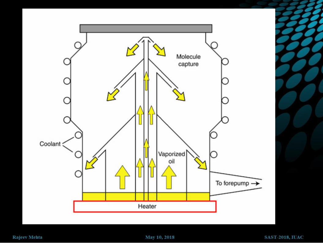
2. Diffusion Pump

•Oil vapor forced through jets in
the stack transfer momentum to
gas molecules and force them
down through the pump and out
the exhaust
•Economical (no moving parts).
•If used with a cryogenic trap,
UHV can be routinely achieved.
•Problem: oil back-streaming
into the vacuum system
3. Turbo Molecular Pump
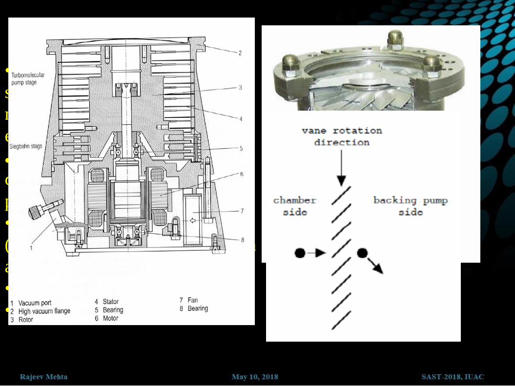
•Turbine blades rotating at high
speed transfer momentum to gas
molecules to force them out to the
exhaust (must be backed).
The pump is characterized by a
compression ratio and ultimate
pressure.
•UHV can be readily achieved
(better if used in combination with
a titanium sublimation pump).
•Sensitive to corrosive gases
•Mechanical wear


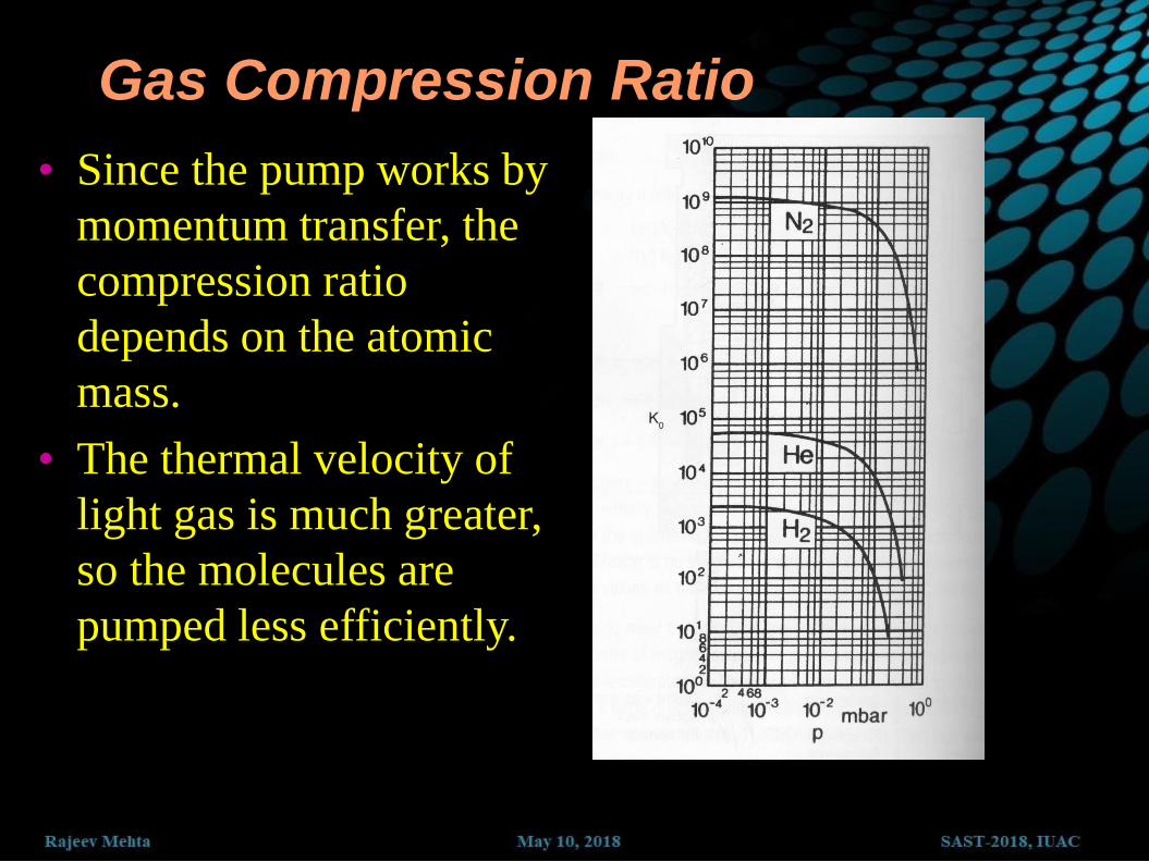
Gas Compression Ratio
• Since the pump works by
momentum transfer, the
compression ratio
depends on the atomic
mass.
• The thermal velocity of
light gas is much greater,
so the molecules are
pumped less efficiently.
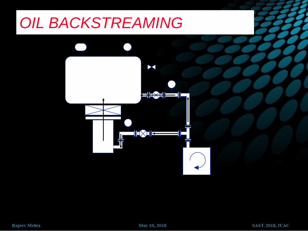
OIL BACKSTREAMING
2
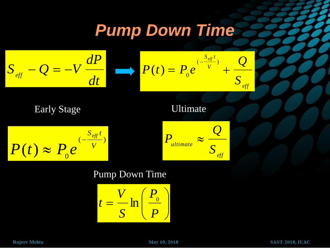
Pump Down Time
dt
dPVQS
eff
eff
V
tS
S
QePtP
eff
)(
0)(
)(
0)( V
tSeff
ePtP
eff
ultimate
S
QP
Early Stage Ultimate
P
P
S
Vt 0ln
Pump Down Time

GAS LOAD
Outgassing
Leaks
Virtual
Real
Backstreaming
Diffusion
Permeation
GAS LOAD (Q) IS EXPRESSED IN:
mbar liters per second
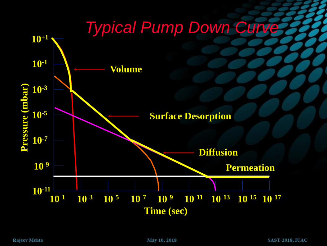
Typical Pump Down Curve P
ress
ure
(m
bar)
Time (sec)
10-11
10 1 10 3 10 5 10 7 10 9 10 11 10 13 10 15 10 17
10+1
10-1
10-3
10-5
10-7
10-9
Volume
Surface Desorption
Diffusion
Permeation

Clean Surface
sec/0.5X10 (torr) P
2 RateImpacr Surface
221cm
TmK
P
B
Assuming a sticking coefficient of 1, time to cover a
clean surface with 1 monolayer of gas is
sec)(
1046
torrP
X

Part 4: Some Practical Aspects

Selection of Fore-pump
QI
QO
SM
SD
PI
PO
QI = Throughput of D.P.
= Pressure x PS DP
QO = Throughput of R.P.
= Fore Pressure x PS RP
QO > QI
PO x SM > PI x SD
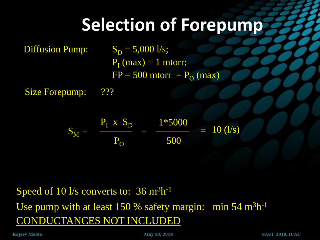
Selection of Forepump Diffusion Pump: SD = 5,000 l/s; PI (max) = 1 mtorr; FP = 500 mtorr = PO (max)
•Speed of 10 l/s converts to: 36 m3h-1
•Use pump with at least 150 % safety margin: min 54 m3h-1 •CONDUCTANCES NOT INCLUDED
SM = PI x SD
PO
500
Size Forepump: ???
=
1*5000 10 (l/s) =

Case 1: A chamber is connected to a pump (300 l/s) through a opening having conductance of 12 l/s => Effective pumping speed is ~ 11.54 l/s
Case 2: Change pump (30000 l/s) => Effective pumping speed is ~ 12 l/s
Solution????????

Differential Pumping
A common requirement is to maintain
part of a system at a relatively low
pressure while another part is at a
relatively high pressure. We need to
calculate the pumping speed S2 required
to maintain the pressure P2
Assume C is small, so
P1 >> P2
then
1
2
2 2 1
LCP CQ
SP P S

VACUUM SYSTEM USE
1
2
4 5
1
2
3
4
5
6
7
8
9
Chamber
High Vac. Pump
Roughing Pump
Hi-Vac. Valve
Roughing Valve
Foreline Valve
Vent Valve
Roughing Gauge
High Vac. Gauge
9 8
8 7
3
6
7

VACUUM SYSTEM OPERATION
1
4
6
5
9
8
8 1
2
3
3a
4
5
6
7
8
9
Chamber
High Vac. Pump
Roughing Pump
Fore Pump
Hi-Vac. Valve
Roughing Valve
Foreline Valve
Vent Valve
Roughing Gauge
High Vac. Gauge
7
3
2
8
2

Start up
Rough Vacuum Gauge : 103 mbar
4
6
5
9
8 7
3
2 2
B : 103 mbar
Rotary Pump On

1.0 x 10⁻² mbar
4
6
5
9
8 7
3
2 2
B : 103 mbar
Roughing Valve open

5.0 x 10⁻² mbar
4
9
8 7
3
2 2
Roughing Valve
Close
Backing Valve Open
5.0 x 10⁻² mbar
Rough Vacuum OK
Backing Vacuum OK
For DP • Start Water Cooling
• Start DP Heater
• Wait 20 minutes
For TP • Start Pump
1.0 x 10⁻³ mbar
8 7
3
2 2
5.0 x 10⁻² mbar
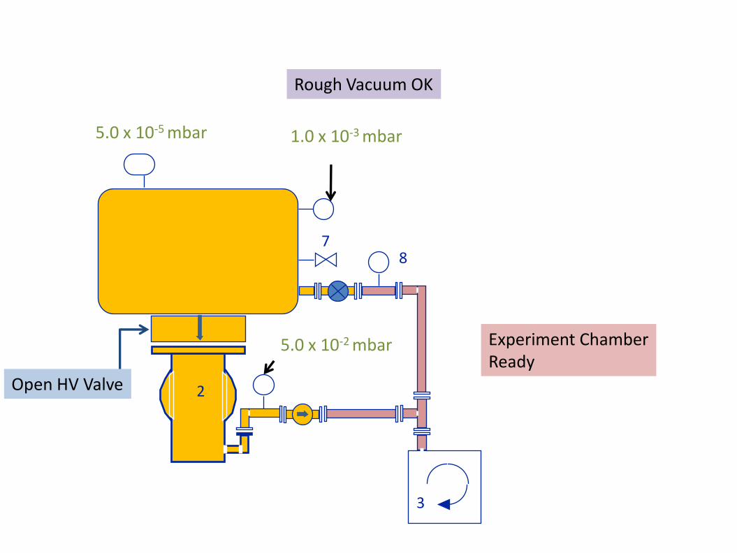
Rough Vacuum OK
Open HV Valve
5.0 x 10⁻⁵ mbar
Experiment Chamber Ready

1.0 x 10⁻³ mbar
8 7
3
2 2
5.0 x 10⁻² mbar
1. Close HV Valve
2. Switch off HV
Gauge
Shut down
3. Switch off heater

1000 mbar
8 7
3
2 2
5.0 x 10⁻² mbar
2. Switch off HV
Gauge
Shut down
Open vent valve
For DP • Wait 30-40 min. for oil to cool • Close backing valve • Stop cooling water
For TP • Close backing valve • Stop the Pump • Vent if required

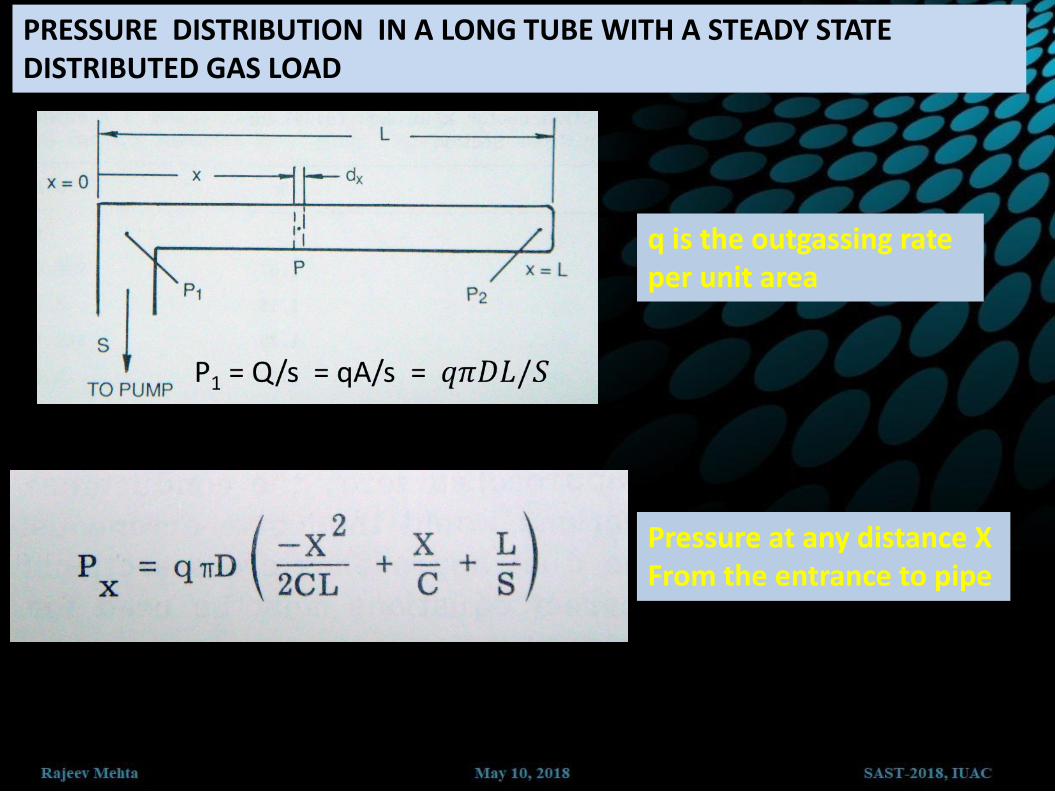
PRESSURE DISTRIBUTION IN A LONG TUBE WITH A STEADY STATE DISTRIBUTED GAS LOAD
q is the outgassing rate per unit area
Pressure at any distance X From the entrance to pipe

Calculate the pressure at the inlet and at 200 cm from inlet of a 10 cm diameter and 300 cm Long stainless steel pipe. Pumping speed at inlet = 100l/s , Outgassing of SS = 5 x 10⁻⁸ Torr. L cm-2s-1
VACUUM TECHNOLOGY
Measuring Devices
----Gauges----
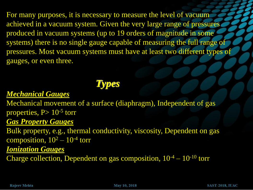
For many purposes, it is necessary to measure the level of vacuum
achieved in a vacuum system. Given the very large range of pressures
produced in vacuum systems (up to 19 orders of magnitude in some
systems) there is no single gauge capable of measuring the full range of
pressures. Most vacuum systems must have at least two different types of
gauges, or even three.
Types Mechanical Gauges
Mechanical movement of a surface (diaphragm), Independent of gas
properties, P> 10-5 torr
Gas Property Gauges
Bulk property, e.g., thermal conductivity, viscosity, Dependent on gas
composition, 102 – 10-4 torr
Ionization Gauges
Charge collection, Dependent on gas composition, 10-4 – 10-10 torr
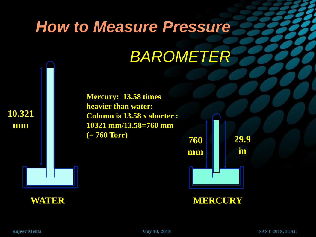
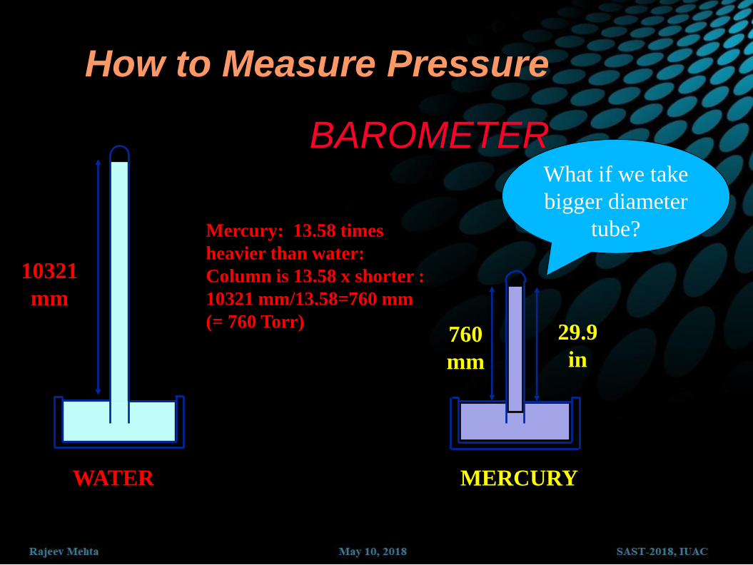
How to Measure Pressure
BAROMETER
WATER
Mercury: 13.58 times
heavier than water:
Column is 13.58 x shorter :
10321 mm/13.58=760 mm
(= 760 Torr)
10.321
mm
MERCURY
760
mm
29.9
in

Pressure is due to fluid weight above it
P = gh P = P
a+gh


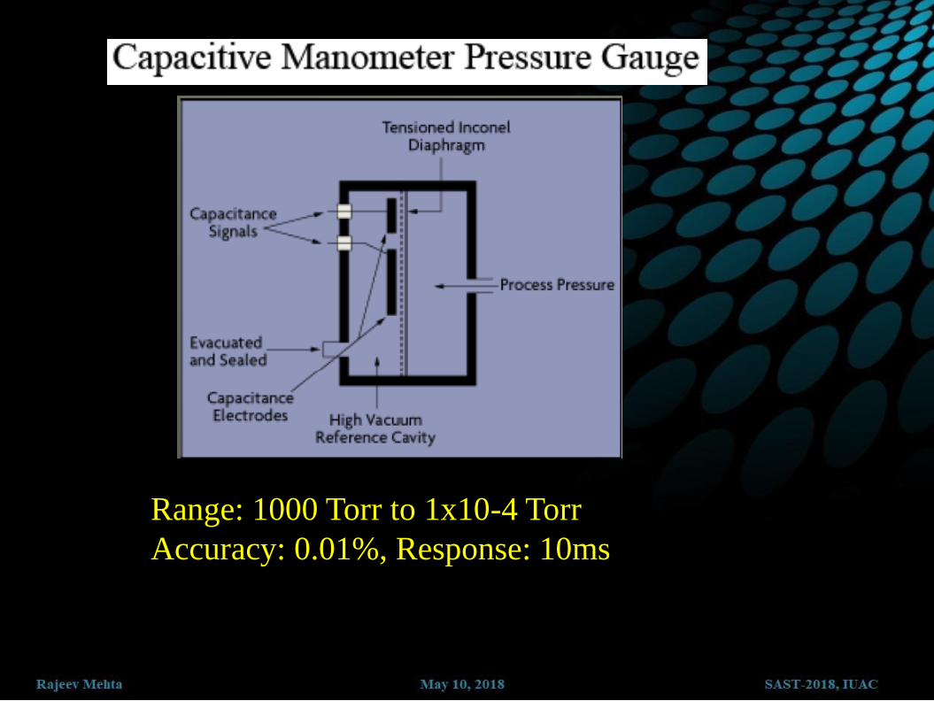
Range: 1000 Torr to 1x10⁻⁴ Torr
Accuracy: 0.01%, Response: 10ms
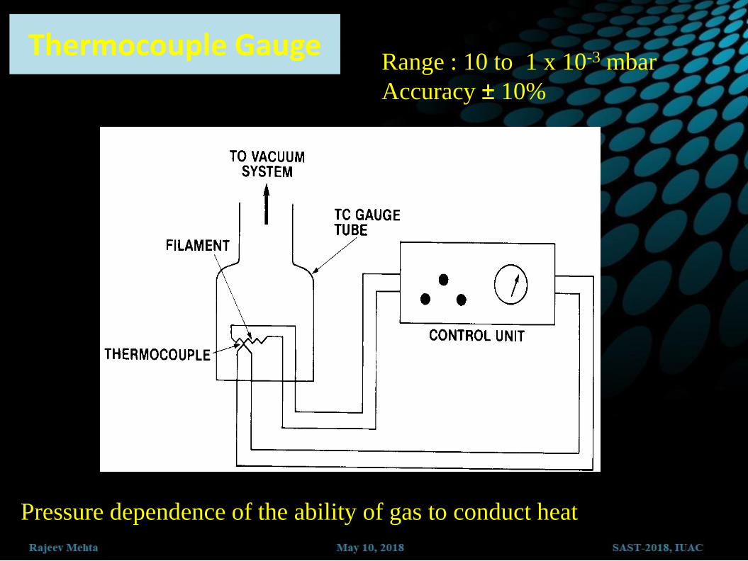
Range : 10 to 1 x 10⁻³ mbar
Accuracy ± 10%
Pressure dependence of the ability of gas to conduct heat
Thermocouple Gauge
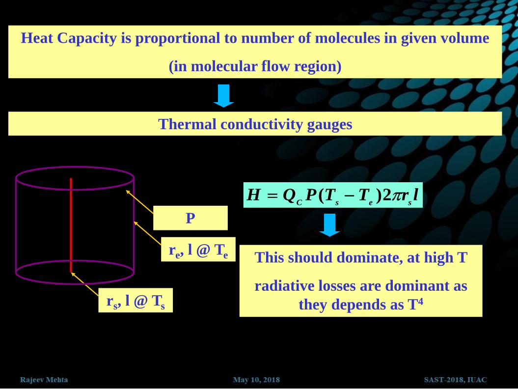
Heat Capacity is proportional to number of molecules in given volume
(in molecular flow region)
Thermal conductivity gauges
rs, l @ Ts
re, l @ Te
P
lrTTPQHsesC
2)(
This should dominate, at high T
radiative losses are dominant as
they depends as T4

How the gauge works
Typical filament temperatures
450OC at 10-3 mbar
40OC at 5 mbar
Above 5 mbar there is not much change in temp.
Not harmed by sudden exposure

Pirani Gauge
• Change in resistance is the measure of vacuum
• Heat loss to environment is proportional to no. of molecules
• At pressures above 10 mbar ?
Range : 1000 to 1 x 10⁻⁴ mbar
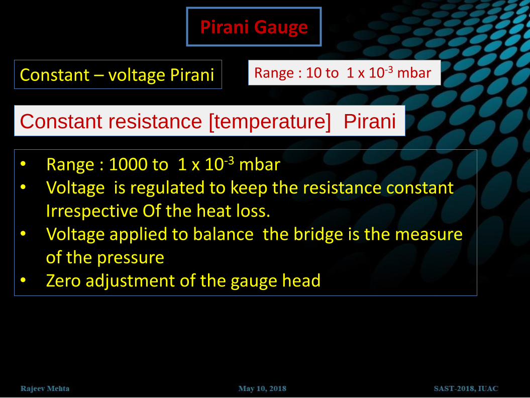
Constant – voltage Pirani Range : 10 to 1 x 10⁻³ mbar
Constant resistance [temperature] Pirani
• Range : 1000 to 1 x 10⁻³ mbar • Voltage is regulated to keep the resistance constant Irrespective Of the heat loss. • Voltage applied to balance the bridge is the measure of the pressure • Zero adjustment of the gauge head
Pirani Gauge

Ionization gauges
• Ionization of gas molecules by electrons • Collection of the Ions • Amplification of the Ion current by sensitive and stable electronics
PRINCIPLE

Mounting of Gauge Heads
WRONG
RIGHT

VACUUM TECHNOLOGY
Leak Detection

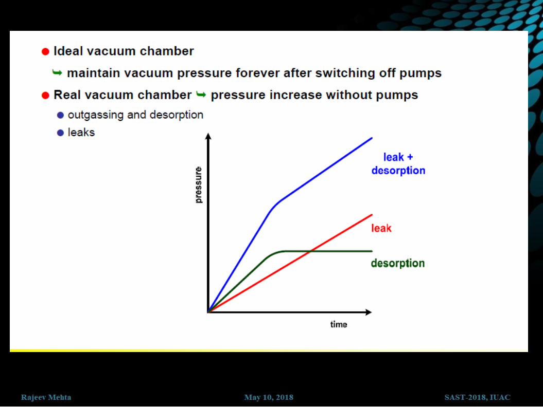
Introduction

The need for leak detection
• Everything leaks! It is a matter of how much of a leak is tolerable.
• Thus the question is:
What is the maximum acceptable leak rate consistent with reasonable performance life of the product?

Kinds of Leaks
• Real Leaks
– Air Leaks
– Porosities
• Permeation leaks
– O-rings
– Glass
•Virtual Leaks
– Outgassing
– Trapped Volumes

Sources of real leaks are:
• Imperfect joints or seals, including:
• Welds
• Brazed joints
• Soldered joints
• Glass to metal seals
• O rings and gaskets etc.
• Imperfections in materials
JOINTS
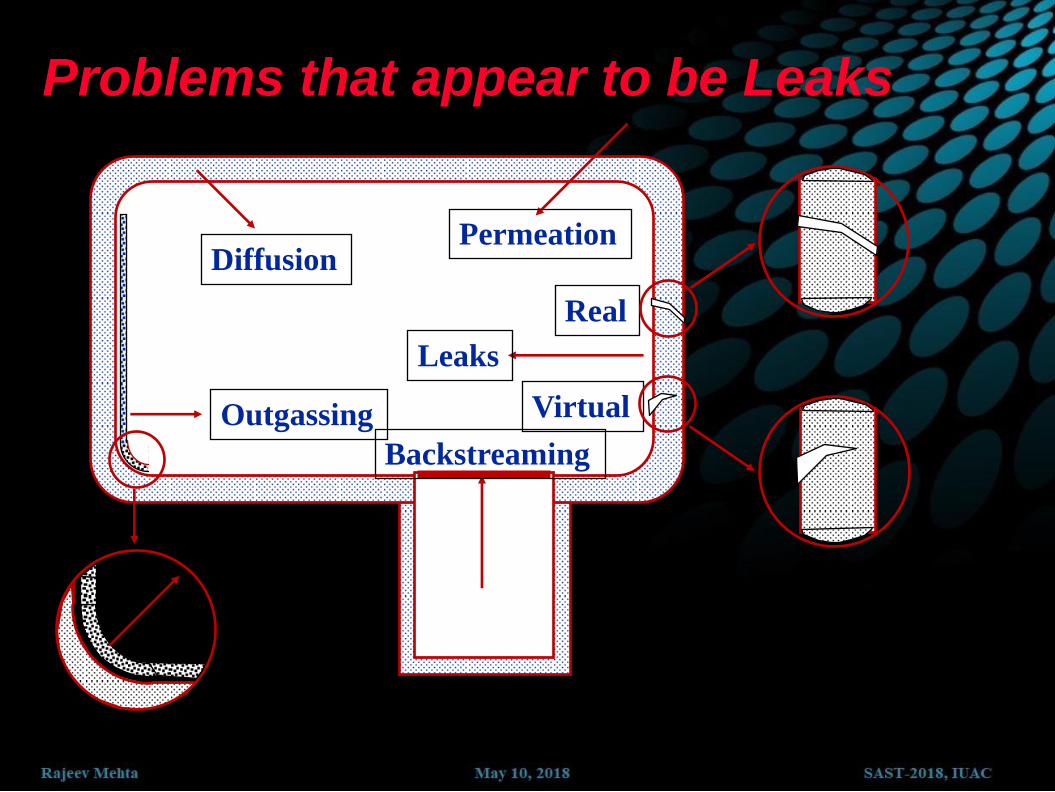
Problems that appear to be Leaks
Outgassing
Leaks
Virtual
Real
Backstreaming
Diffusion Permeation
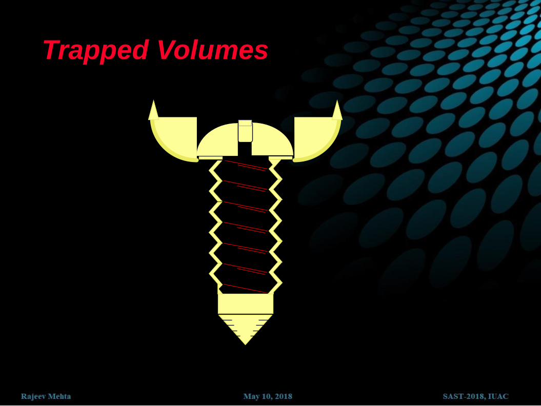
Trapped Volumes

Leak Rates over Time
LEAK RATES
10 -1 STD CC/SEC --- 1 CC/10 SEC
10 -3 STD CC/SEC --- 3 CC/HOUR
10 -5 STD CC/SEC --- 1 CC/DAY
10 -6 STD CC/SEC --- 1 CC/2 WEEKS
10 -7 STD CC/SEC --- 3 CC/YEAR
10 -9 STD CC/SEC --- 1 CC/30 YEARS

Why helium is used ?
Helium is very light and small
Low concentration in air (0.0005%)
Permits dynamic testing
Permits non-destructive testing
Helium is safe
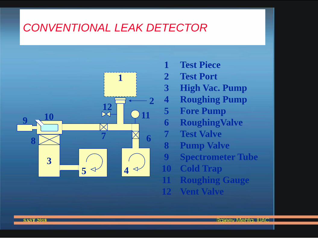
CONVENTIONAL LEAK DETECTOR
1
2
3
4
5
6
7
8
9
10
11
12
Test Piece
Test Port
High Vac. Pump
Roughing Pump
Fore Pump
RoughingValve
Test Valve
Pump Valve
Spectrometer Tube
Cold Trap
Roughing Gauge
Vent Valve
5
1
2
7 6
12 11
4
8
9 10
3
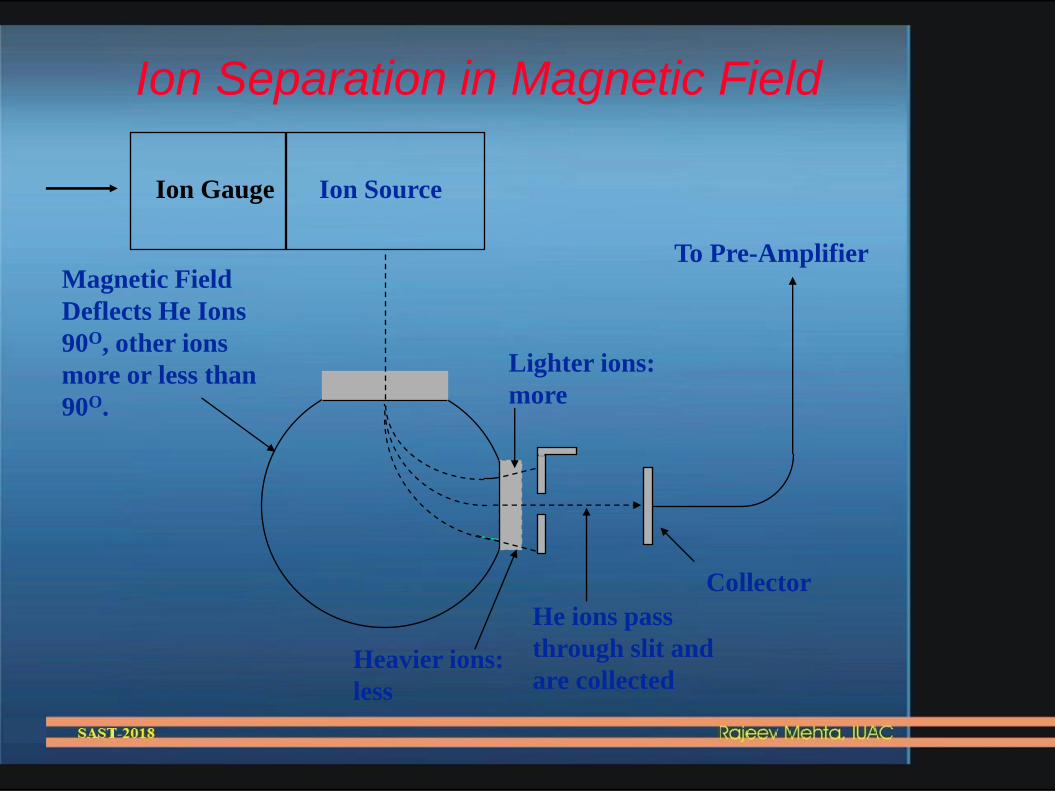
Ion Separation in Magnetic Field
Ion Source
To Pre-Amplifier
Collector
Magnetic Field
Deflects He Ions
90O, other ions
more or less than
90O.
He ions pass
through slit and
are collected
Lighter ions:
more
Heavier ions:
less
Ion Gauge

Tracer probe leak detection technique
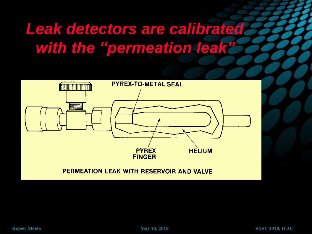
Leak detectors are calibrated
with the “permeation leak”


A permanently evacuated and sealed device and working pressure
is below 10-5 torr. If the volume is 2cm3 estimate the life of the
device if a leak = 1 x 10⁻⁷ torr l/s is there in the device.
1 x 10-5 x 2
1 x 10-7 x 1000 =
= 0.2 s
Quartz and Pyrex : UHV – He Leak
Ceramics – Alumina : Good internal parts
Brass : Contains Zinc – Outgasses at 10-6
OHFC Copper : reduces outgassing for heating
Stainless Steel 300 series (304, 316) : Weldable
Aluminum 6000 series : Porous and Oxide surface – outgasses
more than stainless
Plastic : Outgas at 10-7
Polyimide, Delron, Kapton – Good, Be careful of wiring shield
Material

Practical Concerns
If 10-3 mol H2O in chamber surface and if the outgas pressure is
10-7 torr, how long it takes to pump down to 10-8 torr when the
pumping speed is 1000 ℓ/s?
Initial pumping throughput is
10-7 torr * 1000 ℓ/s = 10-4 torr ℓ/s
Total amount of water is
1 atm * 2.4x10-2 ℓ = 760 torr * 2.4x10⁻² ℓ = 1.8 x 101 torr ℓ
Pump out time constant = t
hr50s101.8/storr10
torr101.8
rateinitial
amounttotalτ
5
4
1

Estimating the effect of Baking
When temperature rises by 100 oC, outgas rate rises by
roughly two orders of magnitude, i.e., 10-5 torr instead of
10-7 torr
Initial pumping throughput is 10-5 torr * 1000 ℓ/s = 10-2 torr ℓ/s
hr5.0s108.1s/torr10
torr108.1τ
3
2
1
to P = 10-10 torr, P0/P = 105
hr11.5P
PlnτΔt 0

Often for a chamber with big surface area
Big chamber ≠ big surface area
How to minimize surface area
Remove thick surface oxide:
electro polish chamber and parts
basic wash, acid wash
Oxide could be porous
Dirty surface is thicker
Strong detergent is much more efficient than solvent Cleaning
ultrasonic bath

bake uniformly is important to avoid distortion
Don’t bake oily surface. oil tar
Aluminum foil on chamber, heating tape on the
aluminum foil, another layer of aluminum foil to
reduce heat loss

Using plastic parts
plastic may absorb H2O to 1~2 % w/w
more troublesome is that most plastics cannot be baked
Use only
Inert material: Teflon, PE, PP, Kel-F, Viton,
Teflon insulated wire
High temperature material : polyimide (Vespel,
Kapton), Kalrez (O-ring)
Bakable to
200oC less inert than Teflon

Material outgas (volume outgas)
SS: H2 & CO.
SS316L can be vacuum firing at 1000 oC to remove
deeper contaminants
Al alloy: less H2 & CO. Bakable to 120 oC
Zn & Cd alloy have high vapor pressure
High temperature increase outgas @ bake out
Cooling can reduce outgas @ use
It lasts forever! More than your life!

Metal seal: copper gasket & ConFlat flange are preferred
Sealing Concern:
100% seal
low outgas
bakable
O-ring seal: Viton O-ring bakable to 100 oC
15 ~ 18 % compression to seal
volume compression is not allowed
sealing surface polish is important
small leak is possible (Hard to find small leaks)
convenient
non-consuming
Careful to use viton gasket on conflat flanges very easy to
leak for size
larger than 4.5” not cheap
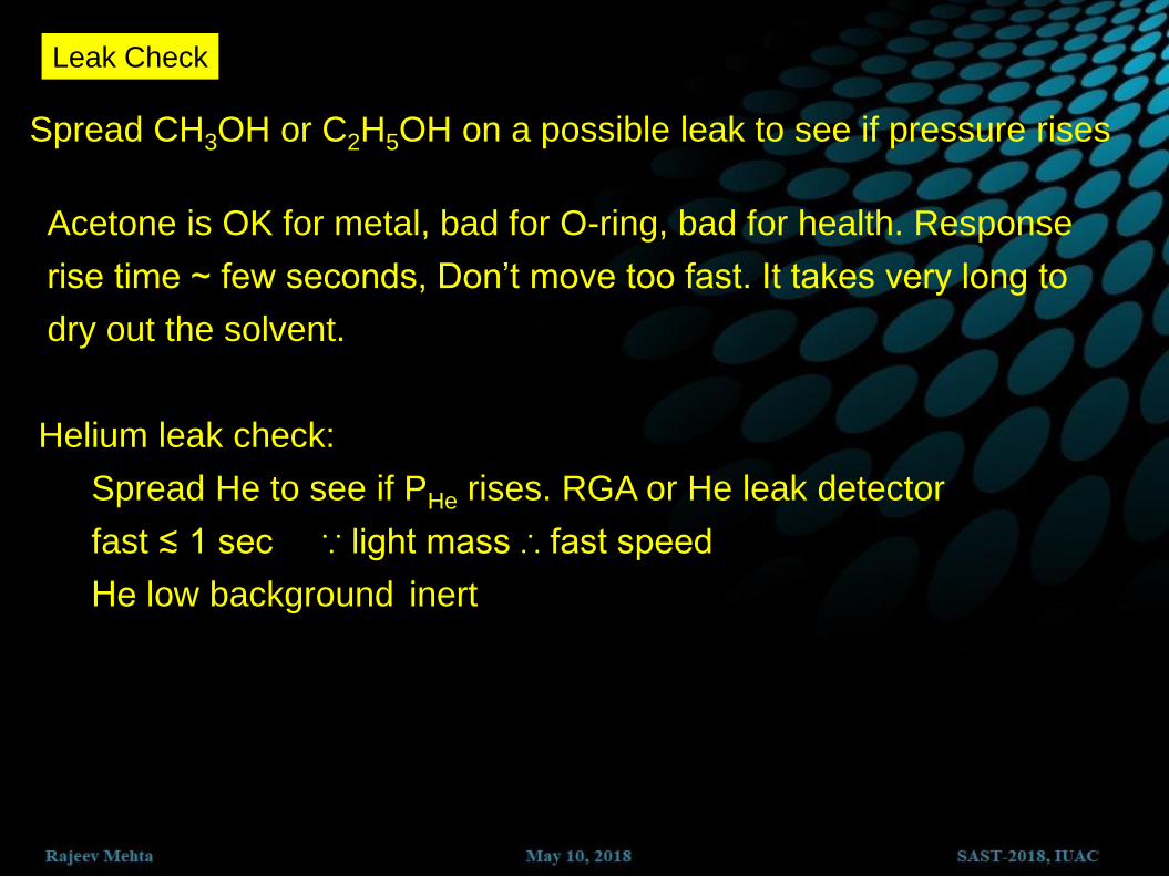
Leak Check
Spread CH3OH or C2H5OH on a possible leak to see if pressure rises
Acetone is OK for metal, bad for O-ring, bad for health. Response
rise time ~ few seconds, Don’t move too fast. It takes very long to
dry out the solvent.
Helium leak check:
Spread He to see if PHe rises. RGA or He leak detector
fast ≲ 1 sec ∵ light mass ∴ fast speed
He low background inert
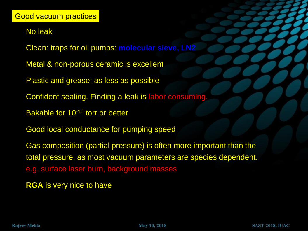
Good vacuum practices
No leak
Clean: traps for oil pumps: molecular sieve, LN2
Metal & non-porous ceramic is excellent
Plastic and grease: as less as possible
Confident sealing. Finding a leak is labor consuming.
Bakable for 10-10 torr or better
Good local conductance for pumping speed
Gas composition (partial pressure) is often more important than the
total pressure, as most vacuum parameters are species dependent.
e.g. surface laser burn, background masses
RGA is very nice to have
Thanks
“A vacuum is a hell of a lot better than
some of the stuff that human replaces it with.”
“Spaghetti can be eaten most successfully if you inhale
it like a vacuum cleaner.”

Multiple Flow Systems

Cold Cathode Gauge/ Penning Gauge

How the Gauge works
Cold Cathode Gauge

• Ionization current is the measure of vacuum
• Range 10-2 to 10-8 mbar
• Loses sensitivity below 10-7 mbar
• Accuracy + 100%, -50%
• 10-5 mbar ~ 5 x 10⁻⁶ mbar / 2 x 10⁻⁵ mbar
• Switch on < 10-2 mbar
• Gets contaminated
• Can be cleaned
Cold Cathode Gauge

6.4 Calibrated Leak
•Known flow of helium (ex., 5.0 x 10⁻⁷ std cc/sec at 20°C)
•Set leak detector scale zero with valve closed
•Leave valve open remainder of time
Valve Pyrex Finger
Port Adapter Helium Filled Reservoir

6. Non Evaporable Getter

• Gas molecules can be sorbed by a chemical reaction when
they impinge on the clean metal surface of the getter
material.
• To achieve a clean metal surface the oxide layer must be
removed in an activation process.
• For that the getter must be heated to a certain temperature.
• During activation the passivating layer diffuses into the
bulk material.
• The metal surface saturates with cumulative sorption of
gas molecules and a new oxide layer will be created.
• To achieve the full pumping speed the NEG must be
reactivated.
Non Evaporable Getter Pumps

NEG Strips
NEG Strips
• ST707 NEG strips
• 350-450°C activation temperature
• High pumping speed and pumping
capacity

water cooling electron channel NEG coating water cooling
NEG Coating
• NEG Coating, Ti-Zr-V, 2μm
• Activation temperature 200 °C
• High pumping speed and low
desorption rate.

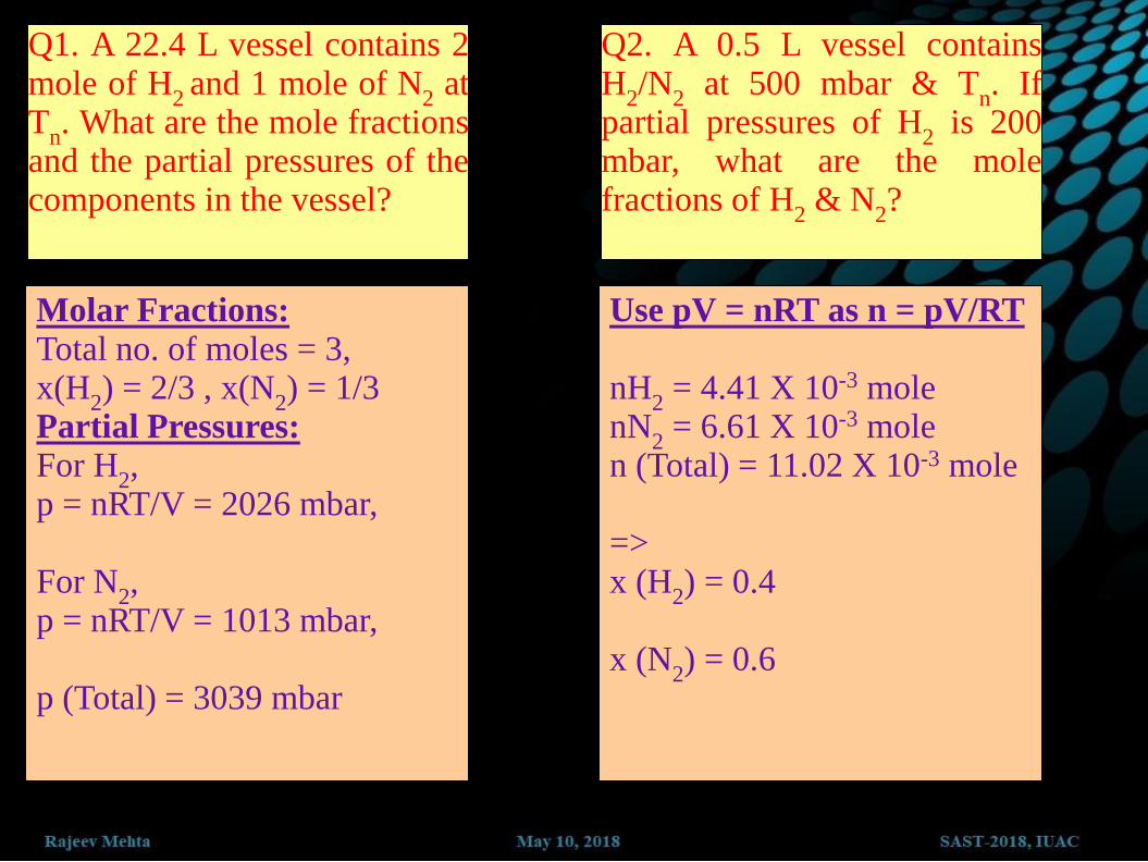
Q1. A 22.4 L vessel contains 2 mole of H
2 and 1 mole of N
2 at
Tn. What are the mole fractions
and the partial pressures of the components in the vessel?
Molar Fractions:
Total no. of moles = 3, x(H
2) = 2/3 , x(N
2) = 1/3
Partial Pressures:
For H2,
p = nRT/V = 2026 mbar, For N
2,
p = nRT/V = 1013 mbar, p (Total) = 3039 mbar
Q2. A 0.5 L vessel contains H
2/N
2 at 500 mbar & T
n. If
partial pressures of H2 is 200
mbar, what are the mole fractions of H
2 & N
2?
Use pV = nRT as n = pV/RT
nH
2 = 4.41 X 10⁻³ mole
nN2 = 6.61 X 10⁻³ mole
n (Total) = 11.02 X 10⁻³ mole => x (H
2) = 0.4
x (N
2) = 0.6

Q1. A 4 L of N2 has a pressure of 500 mbar at 20°C. What is the mass of the
gas?
Q2. The composition of dry air in % volume is as follows : N
2=78.1, O
2=20.9, Ar=0.9, CO
2=0.03 and other 0.07
Find the partial pressure of each at Tn when total pressure is p
n.
Q3. The interior of a spherical vessel of radii 0.5 m is covered with monolayer of a gas particles each having cross sectional area of 10-19 m2. Find the increase in the pressure if all the particles are desorbed at 300°C.
Q4. Calculate the mean free path of N2 (molecular diameter = 3.7A ) at 1 torr
and 293 K.

Q1. What is the average velocity of gas molecules in terms of its molecular weight and temperature ? Fine this for nitrogen molecule at 20C
Q2. What is mean free path? What is the relationship between pressure and mean free path of a molecule. At 25C for nitrogen find number of molecules/cm3 and the mean free path at following pressures (in torr) a) 760 b) 1 c) 10-6
Q3. Find the relationship between following units Torr, mtorr, Pascal, atmosphere, mmHg and bar
Q4. Describe basic fluid flow regimes. How does it depends on characteristic dimension of the system.

Q1. For a system with gas load of 110-5 torr l/sec, required ultimate vacuum is 110-7 torr. System is connected with a pump by a cylindrical 4” long tube of diameter 2.5”. Find a suitable pump for this system. Can you improve on this system?
Q2. How can one determine the pumping speed of a pump experimentally?
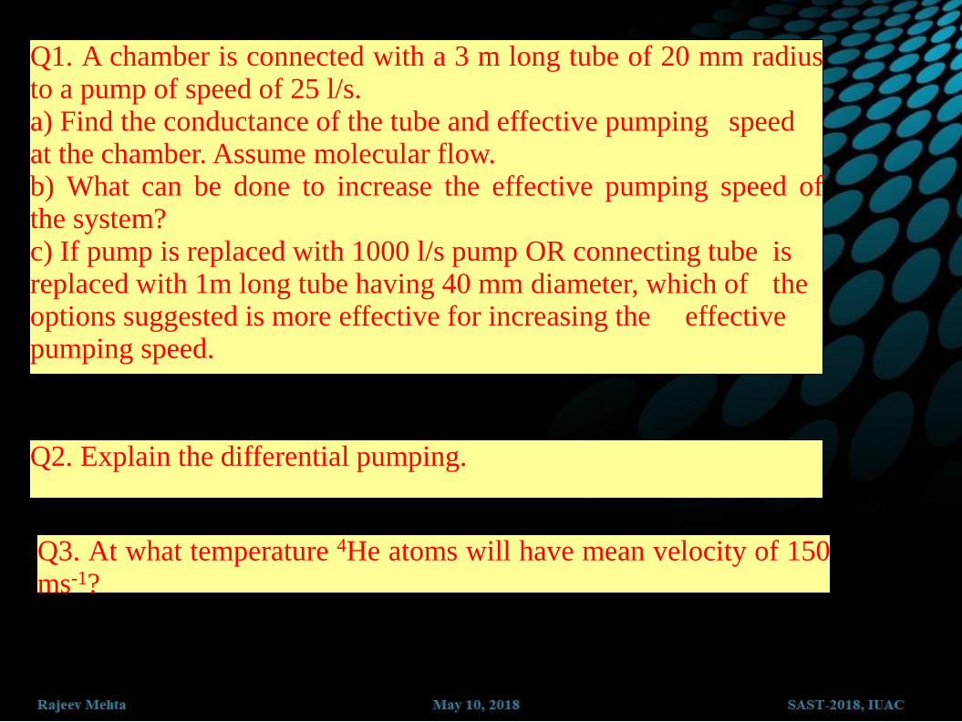
Q1. A chamber is connected with a 3 m long tube of 20 mm radius to a pump of speed of 25 l/s. a) Find the conductance of the tube and effective pumping speed at the chamber. Assume molecular flow. b) What can be done to increase the effective pumping speed of the system? c) If pump is replaced with 1000 l/s pump OR connecting tube is replaced with 1m long tube having 40 mm diameter, which of the options suggested is more effective for increasing the effective pumping speed.
Q2. Explain the differential pumping.
Q3. At what temperature 4He atoms will have mean velocity of 150 ms-1?

Sorption Pump – Design and Physics
• Uses cryosorption to pump gases
• Liquid nitrogen cools the exterior of the pump to 75K (-196o C) and internal fins aid in cooling of sieve material
• Cooled porous trapping material (zeolite, charcoal) is used to cryosorb the gases entering the pump inlet
• Can be easily re-activated by warming to room temperature and removing stopper

Sorption Pump – Bank Design
• Banks of 2 or more
sorption pumps are often
staged together
• Faster pumping speeds are
achieved by connecting
the pumps in parallel
• Lower base pressures are
reached by operating a
bank of pumps in series
Rouging of 200 L volume using a bank of 3 pumps in series
Sorption Pump - Pros and Cons
• Pros
– Clean, oil free
roughing pump
– High pumping
speeds
– Inexpensive
– Easily regenerated
– Durable
• No moving parts
• Cons
– Limited base
pressure range
– Finite pumping
capacity
• Determined by
pump volume and
gas species

Roughing pump comparisons
Oil Sealed Pumps
Type Advantages Disadvantages
Rotary Vane
Low ultimate pressure.
Low cost
Long pump life.
Backstreams oil.
Produces hazardous
waste.
Rootes Lobe Very high pumping
speed.
Frequent maintenance.
Requires a purge gas.
Requires a backing
pump.
Must be absolutely
horizontal.

Roughing pump comparisons
Dry Roughing Pumps
Scroll
Clean.
Low "dry" ultimate
pressure.
Easily servicable
Quiet.
Evolved from air
conditioning
compressor so
technology is
well known.
Limited bearing life.
Limited scroll life.
Permeable to small
gases.
Not hermetically
sealed.
Clean applications
only.
Sorption Clean.
No moving parts.
Requires LN2.
Requires regeneration.
Limited capacity.

4. Ion Pump & Getter Pump

A high voltage combined with a
magnetic field causes electrons to
travel in a helical path with an energy
sufficient to ionize gas atoms.
The ions are accelerated so they strike
a Ti plate and become buried in the
plate.
• Can be started below 10-6 mbar.
• Pumping speed is gas dependent and drops off below 10-9 mbar.
• Buries the gas in the plate, so no backing pump is required.
• A little less expensive than turbo pumps.

Voltage ~ 3000 – 7000 V DC
B ~ 1000 – 2000 Gauss

Sublime Ti-Mo,
continuous/pulse
Chemical reaction
Gas selective: no inert gas

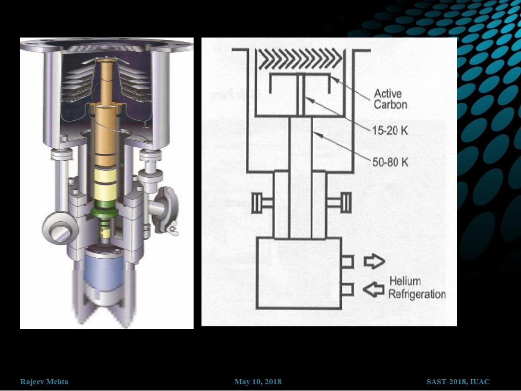
5. Cryo Pump

Cryopump – Physics • Uses cryocondensation, cryosorption as
well as cryotrapping to pump gases
• Cryocondensation happens when gas
molecules impinge on the cold surface
and adhere to the surface
• Cryosorption occurs when the gas is
adsorped by the surface
• Cryotrapping happens when the gases at
the surface are trapped in the growing
solid layer of a second gas.
• As gas enters pump heavier gas
molecules are captured by the first array.
• Lighter, harder to trap gases are captured
at the colder second array

Cryopumps - Design • Liquid He and liquid N used to cool the
system
• 1st stage array is held around 75K by
LN2
• 2nd stage array is held around 4K by
LHe
• 3rd stage array is held around 4K by
LHe
• Closed-loop, gaseous
helium refrigerator to cool
the system.
• 1st stage array is held
around 50K-80K
• 2nd stage array is held
around 10K-20K

Cryopump – Pros and Cons
• High speed pumping
• Clean, oil free pumping
• Easy regeneration
• Has ability to perform
several pumpdown cycles
before regeneration
• Durable
– No moving parts
• Can be rebuilt by various
specialists
• High pumping speed models
can be expensive
• Limited pumping capacity
before regeneration

Ultimate Vacuum
Steady decrease
interrupted by gauge
limitations 1920-1950
Bayard-Alpert gauge
introduced in 1950
Plateau ~1x10-14 Torr
for nearly 3 decades
again
10-14
Ultim
ate
Vacuum
(Torr
)
10-6
10-12
P.A. Redhead Vacuum 53 (1999) 137
10-10
10-8

Some Other Pumps
Turbo molecular pump: ultra-fast fan blades
knock molecules out of vacuum system
Cryo pump: molecules are frozen out
Sorption pump: molecules diffuse into
absorbing material
Sputter ion pump: molecules are ionized and
buried

Cold Traps
Purpose :
Prevents pump oil from
contaminating vacuum system
Prevents organic solvents from
reaching pump (and degrading oil and
seals)
Acts as a pump by condensing
molecules
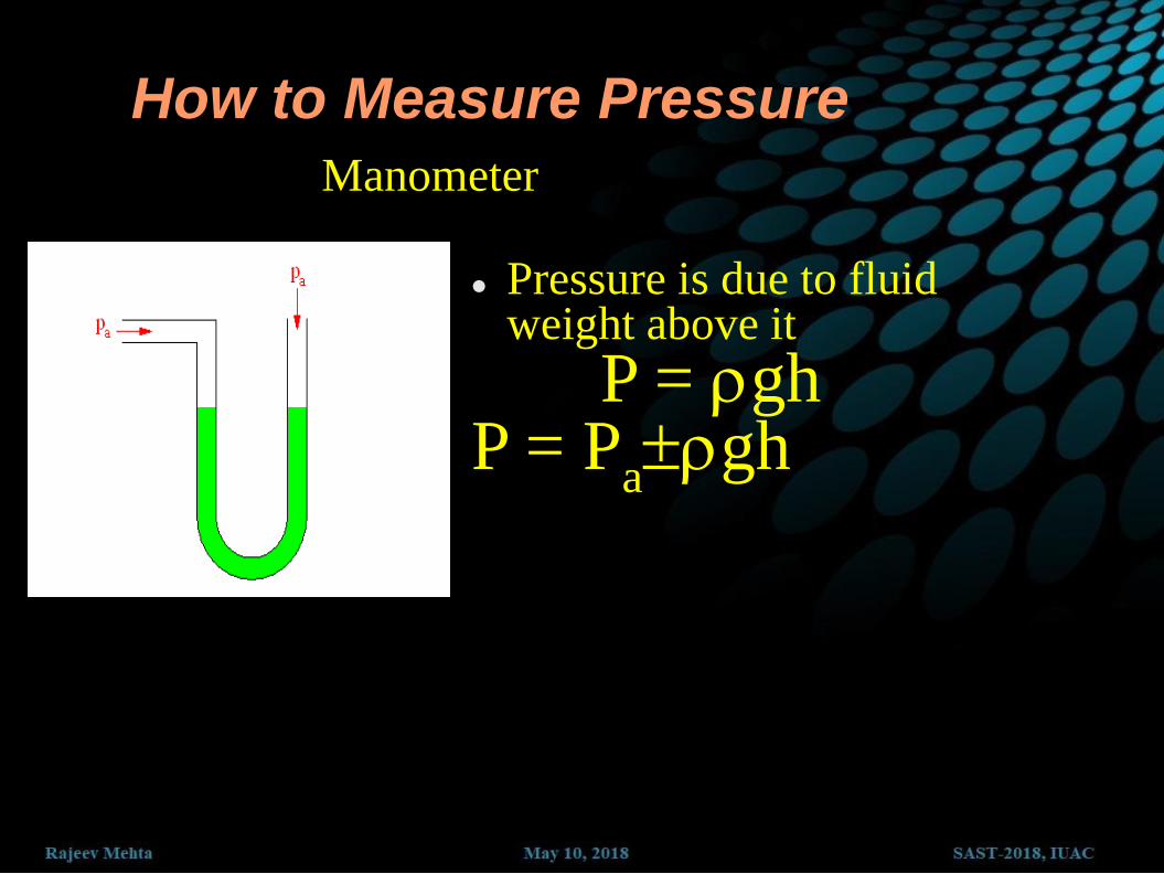
How to Measure Pressure
Manometer
Pressure is due to fluid weight above it
P = gh P = P
agh
How to Measure Pressure
BAROMETER
WATER
Mercury: 13.58 times
heavier than water:
Column is 13.58 x shorter :
10321 mm/13.58=760 mm
(= 760 Torr)
10321
mm
MERCURY
760
mm
29.9
in
What if we take
bigger diameter
tube?