veristore - comint systems · veristore precision applications ltd ... voip page 27...
TRANSCRIPT

Veristore
Precision Applications LtdLodge Hill Industrial ParkWestbury-sub-MendipWellsSomersetBA5 1EYENGLAND
Tel: +44 (0) 1749 870525
Fax: +44 (0) 1749 870912
Email: [email protected]
Web: www.precisionapplications.com
Veristore Recording Solutions
ISSUE 3 Page 1
Control Tower at TAG Farnborough
Contents
1. Introduction Page 3
2. System Overview Page 4
2.1 Voice and Data Recorder Page 52.1.1 Veristore FieldPro Recorder Page 8
2.2 Screen and CCTV Recorders Page 92.3 Central Management System Page 11
2.3.1 Data Access Page 122.3.2 Live Monitoring Page 122.3.3 Data Replay Page 13
Voice Channels Page 13At-the-Glass (Screen Capture) Radar Data Page 14Through-the-Wall (Plot Extracted) Radar Data Page 14Data Replay at an alternative location Page 16Quarantine (secure) Data Files Page 17Data Export Page 17
2.3.4 Alarms Page 182.3.5 System Log and Alarm Log Page 18
2.4 Remote Replay Station Page 202.5 Veristore Replay Software Page 202.6 Timecode and Network Distribution Unit Page 212.7 Audio Unit Page 212.8 Power Management Page 21
3. Typical Veristore System Page 22
4. Data Interfacing Page 24
4.1 Analogue Audio Page 244.2 Digital Audio Page 254.3 VoIP Page 254.4 Ambient Microphones Page 254.5 Through-the-Wall (Plot Extracted) Radar Data Page 264.6 At-the-Glass (Screen Capture) Radar Data Page 264.7 CCTV Page 26
Veristore Recording Solutions
ISSUE 3 Page 2
Control Tower at TAG Farnborough
Contents (contd.)
5. Technical Specifications Page 27
Audio (Voice) Channels Page 27Analogue (Radio / Telephone Inputs Page 27Digital Page 27VoIP Page 27Through-the-Wall (Plot Extracted) Radar Page 28At-the-Glass (Screen Capture) Radar Page 28CCTV Page 28Alarm Output Page 29Master Time Source Page 29Power Requirements Page 30Environmental Conditions Page 30Dimensions and Weight Page 31Warranty Page 31Maintenance Contracts Page 31Support Page 31
Veristore Recording Solutions
ISSUE 3 Page 3
Control Tower at TAG Farnborough
1. Introduction
ATC providers have to record any information that could influence decisions that are made by Air
Traffic Controllers. The recorded information may then be replayed and analysed when there is a
need to investigate incidents or accidents that have occurred. This may be a few seconds after the
recording was made, when a controller or supervisor wishes to listen to a message or conversation
that was not clear, or it may be sometime in the future when an investigator needs to try and
determine why a decision had been made. All of the information must be available for immediate
replay and able to be selected and recovered with the minimum delay.
The latest requirements for ATC Recording have been written to take into account the statement from
Accident Investigators that their work would be greatly assisted if it were possible to see exactly ‘what
was presented to the controller’ and to hear ‘what was said’. A very large amount of data, in a number
of different formats, from many different sources, is continuously presented to each controller and
there are occasions when split-second decisions have to be made. It is therefore essential that all of
the available information is collected, captured and recorded without error. When it is replayed it is
imperative that it is complete and accurately time-sychronised to ensure that it is truly representative
of the information that was presented to the controller.
Veristore Record and Replay Systems are designed
specifically for use in modern ATC environments and are
fully compliant with all of the current ICAO standards.
Veristore Recording Solutions
ISSUE 3 Page 4
Control Tower at TAG Farnborough
2. System Overview
The underlying philosophy behind Veristore is that each data source is directly interfaced to the
recorder which will be used to record the data. This not only guarantees the security of the recorded
data by avoiding the need to transfer it from one storage location to another with multiple write and
read operations but also allows the optimum technology to be used for acquiring and recording each
type of data.
In an ATC environment, controller voice communications are the most important information to be
recorded and in order to achieve true 100% redundancy for these signals, two identical Voice and
Data recorders, which do not communicate with each other, are used in each system.
All of the data is recorded continuously without the use of coding or compression and is subjected to a
‘read-after-write’ check. Therefore there will be two totally independent, complete and accurate copies
of the controller voice communications, both of which will be stored for a minimum of 31 days. A user
may therefore present a Safety Case, for the recorders to be used, without external archiving, to their
appropriate regulatory authority.
If either the regulatory authority or local operating procedures demand that the data is to be archived
to external media it may be copied, either automatically or under manual control, to mini drives.
The ICAO SARPS require that radar data, both raw (Through the Wall) and screen capture (At the
Glass), and Ambient Microphones are recorded and may be replayed synchronously with the voice
data. Veristore Recording Systems will record data from all of the specified sources and replay them
in perfect synchronism.
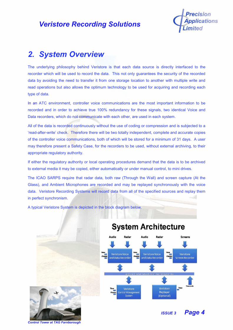
A typical Veristore System is depicted in the block diagram below.
Veristore Recording Solutions
ISSUE 3 Page 5
Control Tower at TAG Farnborough
2.1 Voice and Data Recorder
The Veristore Voice and Data Recorder is a future proof hardware
recorder designed specifically for the Air Traffic Community.
The heart of a Veristore system is the Voice and Data Recorder which has a number
of unique features:
It is a future proof hardware-based recorder which does not use COTS
technology.
It is self-contained and runs totally independently of any system software or
computer operating system.
The record process is controlled by Static Code which has no run time loaded
functions and is designed to operate with unchanging hardware, as mandated
to meet the requirements of IEC61508 SIL4.
Communication with the recorder is via the Interface PC which is used to
provide access to the recorded data but cannot affect the record process or the
recorded data in any way.
It therefore offers the best of both worlds having the benefits
of a purpose designed hardware recorder with the
convenience of a straightforward, intuitive software interface.
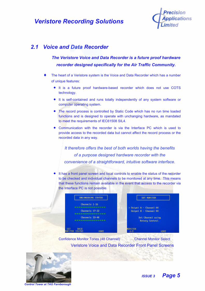
It has a front panel screen and local controls to enable the status of the recorder
to be checked and individual channels to be monitored at any time. This means
that these functions remain available in the event that access to the recorder via
the Interface PC is not possible.
Confidence Monitor Tones (48 Channel) Channel Monitor Select
Veristore Voice and Data Recorder Front Panel Screens
Veristore Recording Solutions
ISSUE 3 Page 6
Control Tower at TAG Farnborough
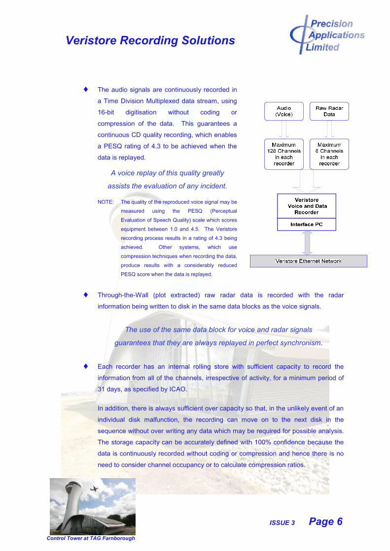
The audio signals are continuously recorded in
a Time Division Multiplexed data stream, using
16-bit digitisation without coding or
compression of the data. This guarantees a
continuous CD quality recording, which enables
a PESQ rating of 4.3 to be achieved when the
data is replayed.
A voice replay of this quality greatly
assists the evaluation of any incident.
NOTE: The quality of the reproduced voice signal may be
measured using the PESQ (Perceptual
Evaluation of Speech Quality) scale which scores
equipment between 1.0 and 4.5. The Veristore
recording process results in a rating of 4.3 being
achieved. Other systems, which use
compression techniques when recording the data,
produce results with a considerably reduced
PESQ score when the data is replayed.
Through-the-Wall (plot extracted) raw radar data is recorded with the radar
information being written to disk in the same data blocks as the voice signals.
The use of the same data block for voice and radar signals
guarantees that they are always replayed in perfect synchronism.
Each recorder has an internal rolling store with sufficient capacity to record the
information from all of the channels, irrespective of activity, for a minimum period of
31 days, as specified by ICAO.
In addition, there is always sufficient over capacity so that, in the unlikely event of an
individual disk malfunction, the recording can move on to the next disk in the
sequence without over writing any data which may be required for possible analysis.
The storage capacity can be accurately defined with 100% confidence because the
data is continuously recorded without coding or compression and hence there is no
need to consider channel occupancy or to calculate compression ratios.
Veristore Recording Solutions
ISSUE 3 Page 7
Control Tower at TAG Farnborough
Longer periods of data retention may be requested if demanded by regulatory
requirements or local procedures.
Extended Availability Hard Disk Drives are essential for reliable, continuous,
24/7 recording and are used exclusively in the recorder store.
NOTE: The disks that Precision Applications specify for use in the Voice and Data Recorder carry a full 5 year manufacturer’s warranty.
Data is written directly to a permanent storage location on disk, using purpose
designed firmware, eliminating potential errors or data loss caused by software
or server errors during data transfers.
Once data is written to the recorder internal store it cannot be altered,
corrupted, over-written or erased.
A data block is written to the internal store each second. Each of these data
blocks is uniquely time stamped with the external time, the recorder internal
time and a sequential block number. This enables data to be accurately located
and replayed synchronously with the data from other recorders in the system.
A ‘Read-After-Write’ check which confirms that the data has been written correctly to
disk is performed immediately after each data block has been written to disk. This
confirms that the data has been received and recorded correctly, without any errors,
and is available for replay in the future.
This is not possible with systems that use either coding or
compression when recording the data or intermediate data storage
locations. In these cases there is no means of knowing that the
data has been recorded correctly until it is requested for replay.
A checksum is calculated and appended to the block prior to writing it to disk.
The block is then immediately read back from disk with the checksum being re-
calculated and compared with the recorded checksum.
A sub-audio Confidence Tone is superimposed on each of the audio channels
to ensure that there is a valid signal path through the entire channel. The
presence of this Confidence Tone is checked as part of the Read-After-Write
check.
Veristore Recording Solutions
ISSUE 3 Page 8
Control Tower at TAG Farnborough
An alarm is raised if any errors are detected in the recorded data or if any of the
sub-audio Confidence Tones are not detected. If an alarm has not been raised
it is certain that the data has been recorded correctly and is available for
immediate replay.
The data, read back from disk as part of the Read-After-Write check, is
immediately available for true Live Monitoring.
The two Voice and Data Recorders may be ‘frame locked’ using a ‘one pulse per
second’ signal which is generated by the Timecode and Network Distribution Unit.
‘Frame locking’ these recorders ensures that they are in perfect time synchronisation
(to within a few microseconds) and audio signals can be simultaneously replayed
from either or both recorders with no time error.
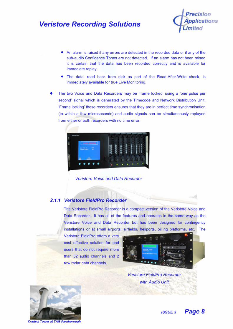
Veristore Voice and Data Recorder
2.1.1 Veristore FieldPro Recorder
The Veristore FieldPro Recorder is a compact version of the Veristore Voice and
Data Recorder. It has all of the features and operates in the same way as the
Veristore Voice and Data Recorder but has been designed for contingency
installations or at small airports, airfields, heliports, oil rig platforms, etc. The
Veristore FieldPro offers a very
cost effective solution for end
users that do not require more
than 32 audio channels and 2
raw radar data channels.
Veristore FieldPro Recorder
with Audio Unit
Veristore Recording Solutions
ISSUE 3 Page 9
Control Tower at TAG Farnborough
2.2 Screen and CCTV Recorders
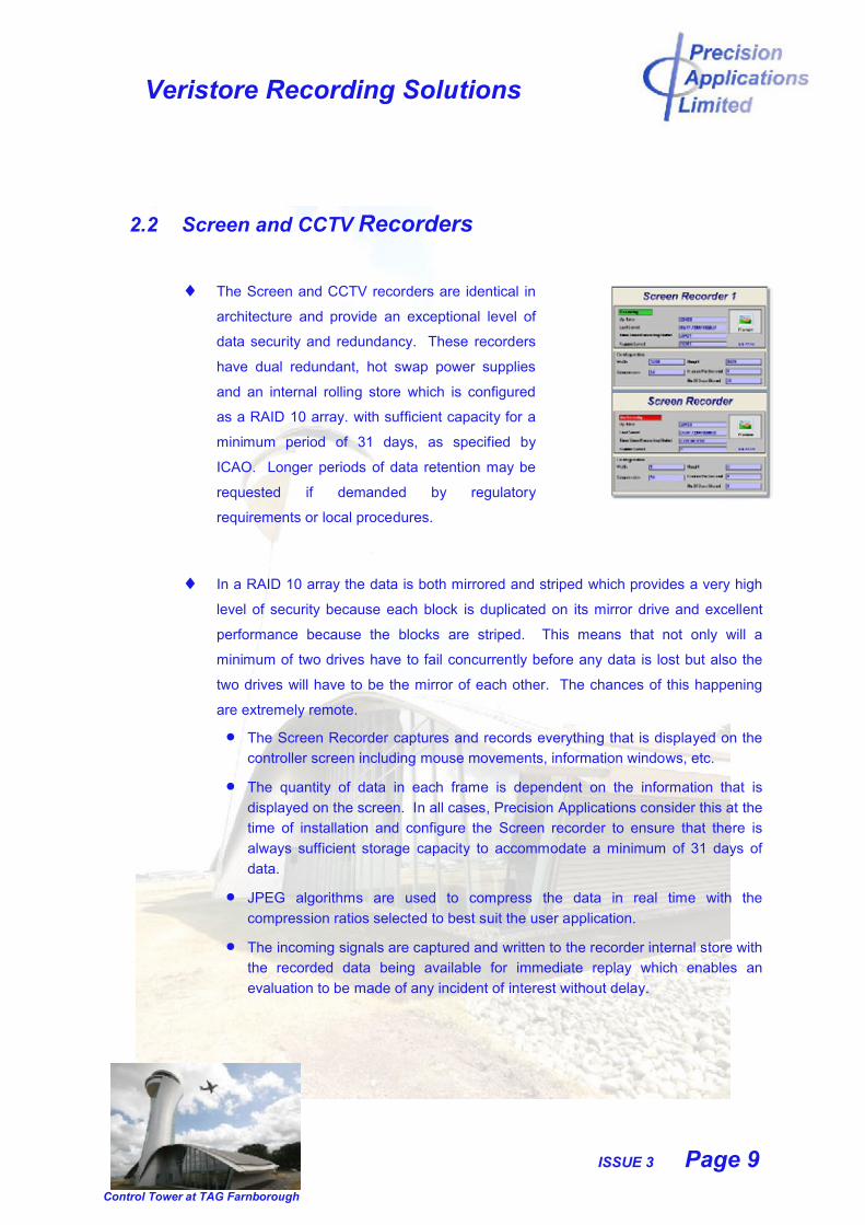
The Screen and CCTV recorders are identical in
architecture and provide an exceptional level of
data security and redundancy. These recorders
have dual redundant, hot swap power supplies
and an internal rolling store which is configured
as a RAID 10 array. with sufficient capacity for a
minimum period of 31 days, as specified by
ICAO. Longer periods of data retention may be
requested if demanded by regulatory
requirements or local procedures.
In a RAID 10 array the data is both mirrored and striped which provides a very high
level of security because each block is duplicated on its mirror drive and excellent
performance because the blocks are striped. This means that not only will a
minimum of two drives have to fail concurrently before any data is lost but also the
two drives will have to be the mirror of each other. The chances of this happening
are extremely remote.
The Screen Recorder captures and records everything that is displayed on the
controller screen including mouse movements, information windows, etc.
The quantity of data in each frame is dependent on the information that is
displayed on the screen. In all cases, Precision Applications consider this at the
time of installation and configure the Screen recorder to ensure that there is
always sufficient storage capacity to accommodate a minimum of 31 days of
data.
JPEG algorithms are used to compress the data in real time with the
compression ratios selected to best suit the user application.
The incoming signals are captured and written to the recorder internal store with
the recorded data being available for immediate replay which enables an
evaluation to be made of any incident of interest without delay.
Veristore Recording Solutions
ISSUE 3 Page 10
Control Tower at TAG Farnborough
Each frame is stored in a data block, which is uniquely time-stamped, using the
same time source as the other recorders in the system. This guarantees that
the data can be replayed synchronously with the data from all other recorders.
Once data is written to the recorder internal store it cannot be altered,
corrupted, over-written or erased.
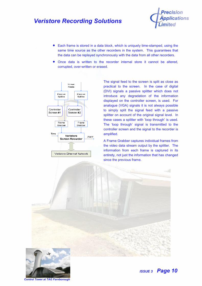
The signal feed to the screen is split as close as
practical to the screen. In the case of digital
(DVI) signals a passive splitter which does not
introduce any degradation of the information
displayed on the controller screen, is used. For
analogue (VGA) signals it is not always possible
to simply split the signal feed with a passive
splitter on account of the original signal level. In
these cases a splitter with ’loop through’ is used.
The ‘loop through’ signal is transmitted to the
controller screen and the signal to the recorder is
amplified.
A Frame Grabber captures individual frames from
the video data stream output by the splitter. The
information from each frame is captured in its
entirety, not just the information that has changed
since the previous frame.
Veristore Recording Solutions
ISSUE 3 Page 11
Control Tower at TAG Farnborough
2.3 Central Management System
The Central Management System (CMS) is the hub of a Veristore Record and
Replay System, communicating with all of the recorders via the Veristore Ethernet
Network.
A straightforward, intuitive, Graphical User Interface enables the User to quickly
and efficiently access the recorders and the recorded data.
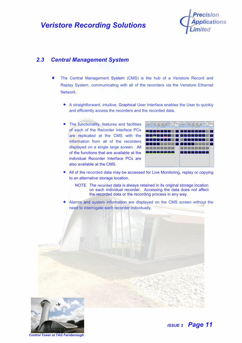
The functionality, features and facilities
of each of the Recorder Interface PCs
are replicated at the CMS with the
information from all of the recorders
displayed on a single large screen. All
of the functions that are available at the
individual Recorder Interface PCs are
also available at the CMS.
All of the recorded data may be accessed for Live Monitoring, replay or copying
to an alternative storage location.
NOTE The recorded data is always retained in its original storage location on each individual recorder. Accessing the data does not affect the recorded data or the recording process in any way.
Alarms and system information are displayed on the CMS screen without the
need to interrogate each recorder individually.

Veristore Recording Solutions
ISSUE 3 Page 12
Control Tower at TAG Farnborough
Any access to the recorders is strictly controlled by
passwords. The use of multiple user types and individual
user passwords enable a security hierarchy to be generated
and maintained.
The passwords and user types are allocated by the
System Administrator, allowing specific personnel or
groups of personnel to be permitted or denied access to
the various functions within the system, ensuring that the
integrity of the system is always maintained.
User permissions may be directly relayed to each of the
recorders in the system which enables any
modifications to be achieved quickly and easily.
2.3.1 Data Access
In a record and replay system it is essential that the recorded data can be located
and retrieved quickly and efficiently. With Veristore all of the data, irrelevant of its
source, can be accessed within a maximum of one second of it having been
received.
2.3.2 Live Monitoring
Data from any source can be ‘live monitored’. In all cases the monitor data is
read from the recorder internal stores and output as part of the ‘Read-After-Write’
process. This confirms that meaningful data has been transmitted to the
recording system, received and recorded without error, giving 100% confidence
that it will be available for replay at a later date.
NOTE: The monitoring of the Ambient Microphone channels is strictly controlled
by password access.
Veristore Recording Solutions
ISSUE 3 Page 13
Control Tower at TAG Farnborough
2.3.3 Data Replay
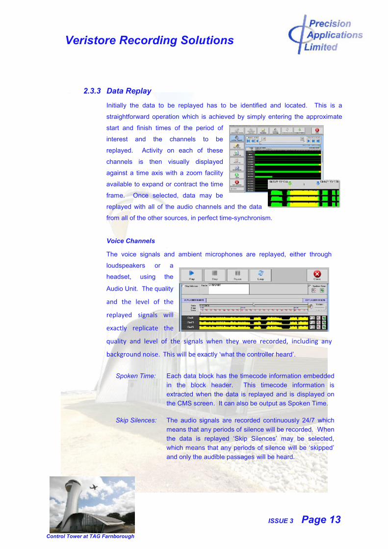
Initially the data to be replayed has to be identified and located. This is a
straightforward operation which is achieved by simply entering the approximate
start and finish times of the period of
interest and the channels to be
replayed. Activity on each of these
channels is then visually displayed
against a time axis with a zoom facility
available to expand or contract the time
frame. Once selected, data may be
replayed with all of the audio channels and the data
from all of the other sources, in perfect time-synchronism.
Voice Channels
The voice signals and ambient microphones are replayed, either through
loudspeakers or a
headset, using the
Audio Unit. The quality
and the level of the
replayed signals will
exactly replicate the
quality and level of the signals when they were recorded, including any
background noise. This will be exactly ‘what the controller heard’.
Spoken Time: Each data block has the timecode information embedded
in the block header. This timecode information is
extracted when the data is replayed and is displayed on
the CMS screen. It can also be output as Spoken Time.
Skip Silences: The audio signals are recorded continuously 24/7 which
means that any periods of silence will be recorded. When
the data is replayed ‘Skip Silences’ may be selected,
which means that any periods of silence will be ‘skipped’
and only the audible passages will be heard.
Veristore Recording Solutions
ISSUE 3 Page 14
Control Tower at TAG Farnborough
Loop Replay: There is a facility to continuously replay passages of
particular interest. Specific periods of data may be
selected for ‘Loop Replay’ when a passage of information
will be replayed as normal and then repeated. The replay
will be repeated until ‘Stop’ is selected.
At-the-Glass (Screen Capture) Radar
When the screen capture information is replayed the controller screen(s) are
displayed exactly as they were captured. It is not possible to alter any of the
information displayed on the screens during replay. Mouse movements, the
opening, closing and scaling of windows and any manipulation of the display
initiated by the controller are replayed exactly as they occurred.
A zoom facility which enables the display to be ‘scaled is available’ and
specific areas of the screen may be selected to aid analysis by giving a
better understanding of the situation.
Individual screenshots, from a replayed sequence, are available in a
format that may be printed.
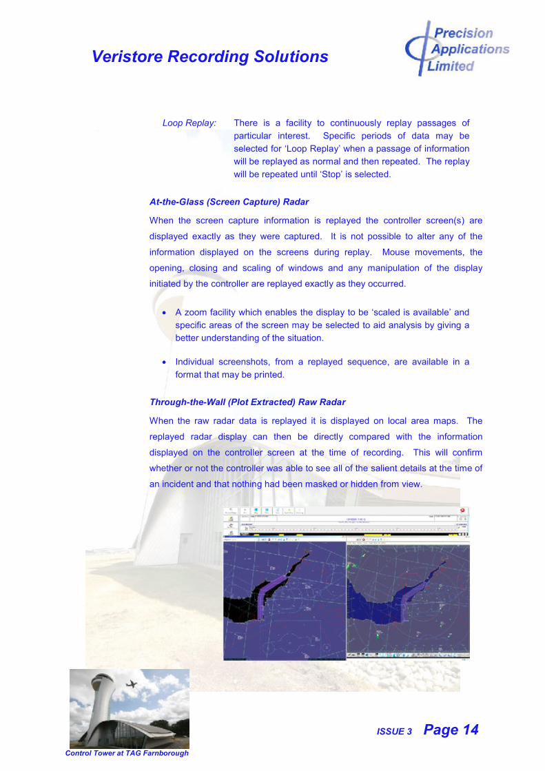
Through-the-Wall (Plot Extracted) Raw Radar
When the raw radar data is replayed it is displayed on local area maps. The
replayed radar display can then be directly compared with the information
displayed on the controller screen at the time of recording. This will confirm
whether or not the controller was able to see all of the salient details at the time of
an incident and that nothing had been masked or hidden from view.
Veristore Recording Solutions
ISSUE 3 Page 15
Control Tower at TAG Farnborough
Analysis tools are included, as a standard feature, in the Veristore Replay
Software. These can aid an investigation by presenting specific information in
more detail and in a manner that is easier to interpret.
The display can be scaled by zooming in or out to provide a clearer
understanding of the situation, as it occurred.
A single aircraft can be highlighted by ‘clicking’ on the trail for that
aircraft with the mouse. The other aircraft will still be displayed on the
screen but they will be ‘greyed-out’. This means that the selected
aircraft will stand out from the others, reducing any possibility of
confusion and permitting its course to be easily tracked.
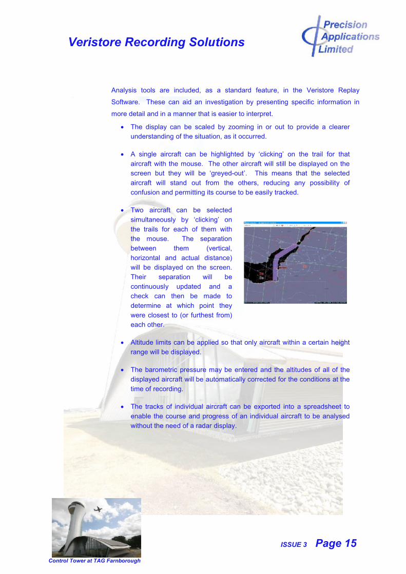
Two aircraft can be selected
simultaneously by ‘clicking’ on
the trails for each of them with
the mouse. The separation
between them (vertical,
horizontal and actual distance)
will be displayed on the screen.
Their separation will be
continuously updated and a
check can then be made to
determine at which point they
were closest to (or furthest from)
each other.
Altitude limits can be applied so that only aircraft within a certain height
range will be displayed.
The barometric pressure may be entered and the altitudes of all of the
displayed aircraft will be automatically corrected for the conditions at the
time of recording.
The tracks of individual aircraft can be exported into a spreadsheet to
enable the course and progress of an individual aircraft to be analysed
without the need of a radar display.
Veristore Recording Solutions
ISSUE 3 Page 16
Control Tower at TAG Farnborough
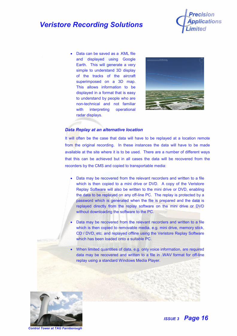
Data can be saved as a .KML file
and displayed using Google
Earth. This will generate a very
simple to understand 3D display
of the tracks of the aircraft
superimposed on a 3D map.
This allows information to be
displayed in a format that is easy
to understand by people who are
non-technical and not familiar
with interpreting operational
radar displays.
Data Replay at an alternative location
It will often be the case that data will have to be replayed at a location remote
from the original recording. In these instances the data will have to be made
available at the site where it is to be used. There are a number of different ways
that this can be achieved but in all cases the data will be recovered from the
recorders by the CMS and copied to transportable media:
Data may be recovered from the relevant recorders and written to a file
which is then copied to a mini drive or DVD. A copy of the Veristore
Replay Software will also be written to the mini drive or DVD, enabling
the data to be replayed on any off-line PC. The replay is protected by a
password which is generated when the file is prepared and the data is
replayed directly from the replay software on the mini drive or DVD
without downloading the software to the PC.
Data may be recovered from the relevant recorders and written to a file
which is then copied to removable media, e.g. mini drive, memory stick,
CD / DVD, etc. and replayed offline using the Veristore Replay Software
which has been loaded onto a suitable PC.
When limited quantities of data, e.g. only voice information, are required
data may be recovered and written to a file in .WAV format for off-line
replay using a standard Windows Media Player.
Veristore Recording Solutions
ISSUE 3 Page 17
Control Tower at TAG Farnborough
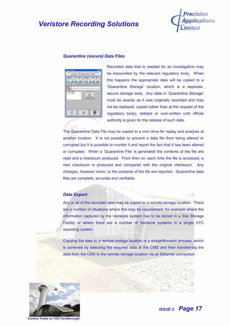
Quarantine (secure) Data Files
Recorded data that is needed for an investigation may
be impounded by the relevant regulatory body. When
this happens the appropriate data will be copied to a
‘Quarantine Storage’ location, which is a separate,
secure storage area. Any data in ‘Quarantine Storage’
must be exactly as it was originally recorded and may
not be replayed, copied (other than at the request of the
regulatory body), deleted or over-written until official
authority is given for the release of such data.
The Quarantine Data File may be copied to a mini drive for replay and analysis at
another location. It is not possible to prevent a data file from being altered or
corrupted but it is possible to monitor it and report the fact that it has been altered
or corrupted. When a ‘Quarantine File’ is generated the contents of the file are
read and a checksum produced. From then on, each time the file is accessed, a
new checksum is produced and compared with the original checksum. Any
changes, however minor, to the contents of the file are reported. Quarantine data
files are complete, accurate and verifiable.
Data Export
Any or all of the recorded data may be copied to a remote storage location. There
are a number of situations where this may be requirement, for example where the
information captured by the Veristore system has to be stored in a Site Storage
Facility or where there are a number of Veristore systems in a single ATC
recording system.
Copying the data to a remote storage location is a straightforward process, which
is achieved by selecting the required data at the CMS and then transferring the
data from the CMS to the remote storage location via an Ethernet connection.
Veristore Recording Solutions
ISSUE 3 Page 18
Control Tower at TAG Farnborough
2.3.4 Alarms
Veristore Recording Systems have a comprehensive alarm structure which is
flexible and may be tailored by the user to their specific requirements.
Hardware (dry contact) alarm signals are generated by the Voice and Data
recorders if a fault is detected that causes the recorder to stop recording. These
signals are independent of the Interface PC software and can be directly
connected to a remote alarm panel to indicate to ATC and ATE that the integrity of
the recording system has been compromised.
The CMS also generates dry contact alarm signals, which may be designated as
‘urgent’ or ‘non urgent’ and connected to a remote alarm panel to indicate to ATE
that a fault in the Recording System has been identified.
Software alarm signals are generated by each of the Interface PCs. The CMS
interrogates the Interface PCs and reports any alarms that have been generated.
These alarms can be designated as ‘urgent’ or ‘non-urgent’ and the user can
determine how they are reported and displayed.
Alarms may be viewed at the CMS and appropriate action taken. An alarm cannot
be cleared until it has been acknowledged and the fault cleared.
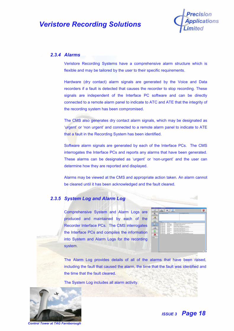
2.3.5 System Log and Alarm Log
Comprehensive System and Alarm Logs are
produced and maintained by each of the
Recorder Interface PCs. The CMS interrogates
the Interface PCs and compiles the information
into System and Alarm Logs for the recording
system.
The Alarm Log provides details of all of the alarms that have been raised,
including the fault that caused the alarm, the time that the fault was identified and
the time that the fault cleared.
The System Log includes all alarm activity.
Veristore Recording Solutions
ISSUE 3 Page 19
Control Tower at TAG Farnborough
All of the entries in the logs are time-stamped and have the relevant user
identification attached. Any access to the recorders is therefore reported by user
identification, date and time.
Each of the logs may be accessed by authorised users and viewed, printed or
saved as a .CSV file.
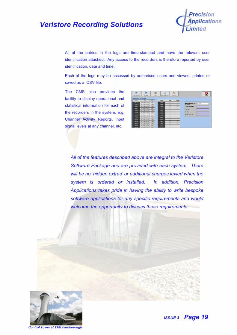
The CMS also provides the
facility to display operational and
statistical information for each of
the recorders in the system, e.g.
Channel Activity Reports, input
signal levels at any channel, etc.
All of the features described above are integral to the Veristore
Software Package and are provided with each system. There
will be no ‘hidden extras’ or additional charges levied when the
system is ordered or installed. In addition, Precision
Applications takes pride in having the ability to write bespoke
software applications for any specific requirements and would
welcome the opportunity to discuss these requirements.
Veristore Recording Solutions
ISSUE 3 Page 20
Control Tower at TAG Farnborough
2.4 Remote Replay Station
All of the Data Replay and Data Transfer functions that are described above for the
Central Management System are available at a Remote Replay Station.
The Remote Replay Station communicates directly with each of the recorders in the
system via the Veristore Ethernet Network. As in the case of the Central
Management System, it provides a straightforward, intuitive, User Interface, based
on the Windows .NET framework and any access to the recorders is strictly
controlled by password.
There is no limit to the number of Remote Replay Stations that may be added to a
Veristore system to provide replay facilities at any required location.
2.5 Veristore Replay Software
The Veristore Replay Software includes all of the Data Replay and Data Transfer
features described above for the Central Management System and may be loaded
on to any suitable PC to provide file and archive replay of the data recorded on a
Veristore Recording System.
Veristore Replay Software is licensed for unlimited use within a user’s site.
Veristore Recording Solutions
ISSUE 3 Page 21
Control Tower at TAG Farnborough
2.6 Timecode and Network Distribution Unit
The Timecode and Network Distribution Unit is the Network Hub for the Veristore
Ethernet Network.
The Master Clock is accepted by the Timecode and Network Distribution Unit in a
number of different formats and distributed to each of the recorders in the system,
the Central Management Unit and the Remote Replay Station(s), ensuring that all of
them are synchronised.
If the Master Clock signal is lost or not recognised by a recorder or the CMS an
alarm will be raised. The timecode signal from the Timecode and Network
Distribution Unit will then ‘freewheel’ until the Master Clock signal is restored.
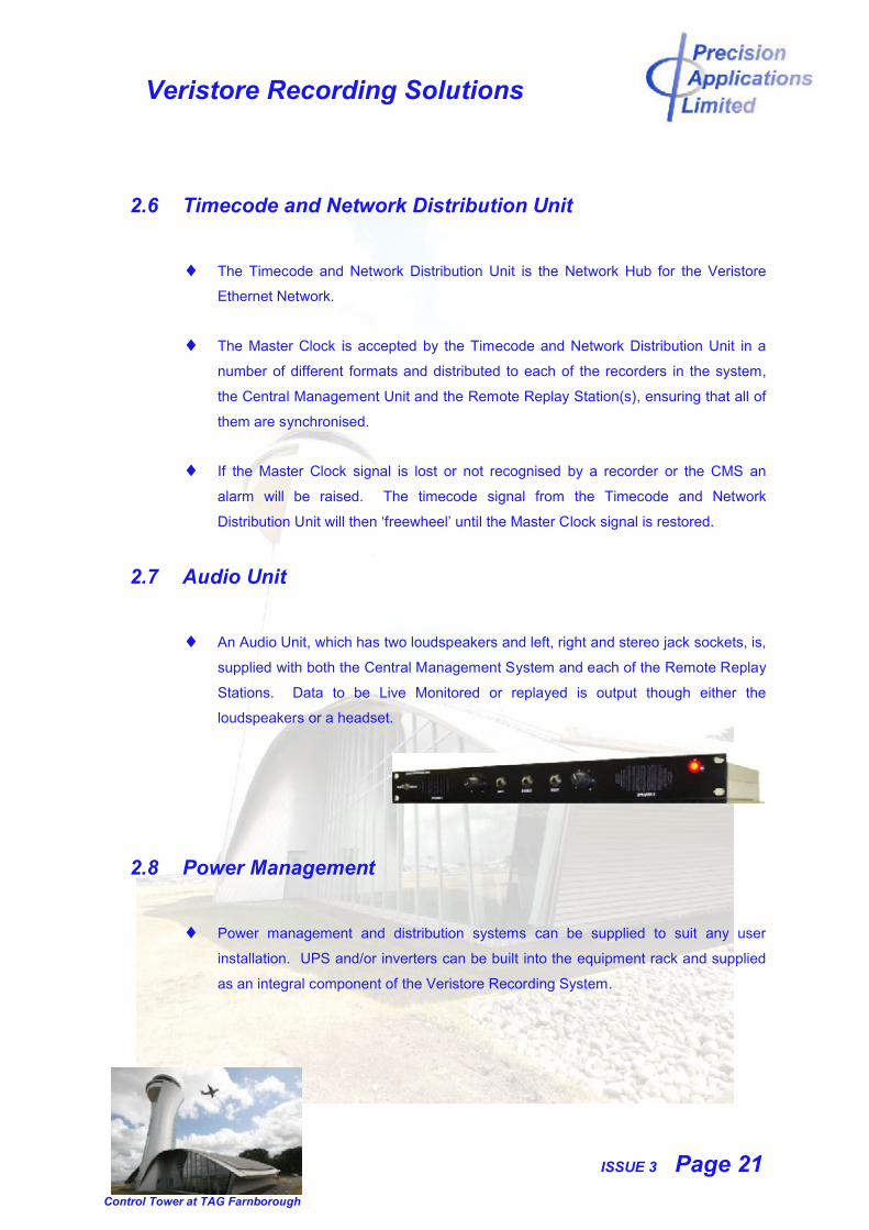
2.7 Audio Unit
An Audio Unit, which has two loudspeakers and left, right and stereo jack sockets, is,
supplied with both the Central Management System and each of the Remote Replay
Stations. Data to be Live Monitored or replayed is output though either the
loudspeakers or a headset.
2.8 Power Management
Power management and distribution systems can be supplied to suit any user
installation. UPS and/or inverters can be built into the equipment rack and supplied
as an integral component of the Veristore Recording System.
Veristore Recording Solutions
ISSUE 3 Page 22
Control Tower at TAG Farnborough
3. Typical Veristore System
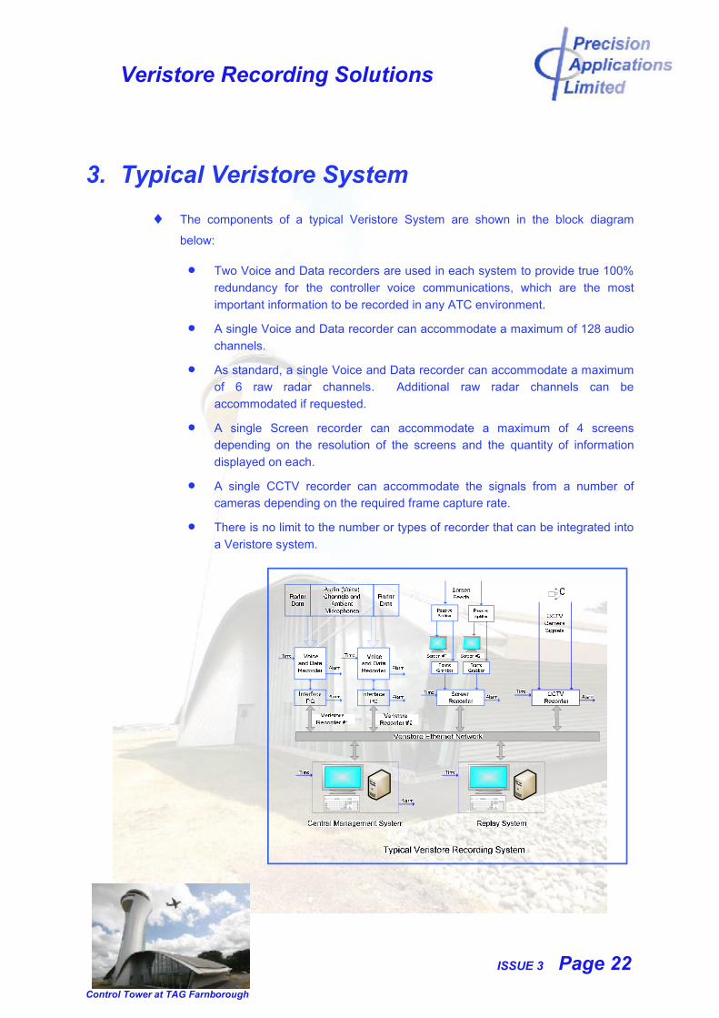
The components of a typical Veristore System are shown in the block diagram
below:
Two Voice and Data recorders are used in each system to provide true 100%
redundancy for the controller voice communications, which are the most
important information to be recorded in any ATC environment.
A single Voice and Data recorder can accommodate a maximum of 128 audio
channels.
As standard, a single Voice and Data recorder can accommodate a maximum
of 6 raw radar channels. Additional raw radar channels can be
accommodated if requested.
A single Screen recorder can accommodate a maximum of 4 screens
depending on the resolution of the screens and the quantity of information
displayed on each.
A single CCTV recorder can accommodate the signals from a number of
cameras depending on the required frame capture rate.
There is no limit to the number or types of recorder that can be integrated into
a Veristore system.
Veristore Recording Solutions
ISSUE 3 Page 23
Control Tower at TAG Farnborough
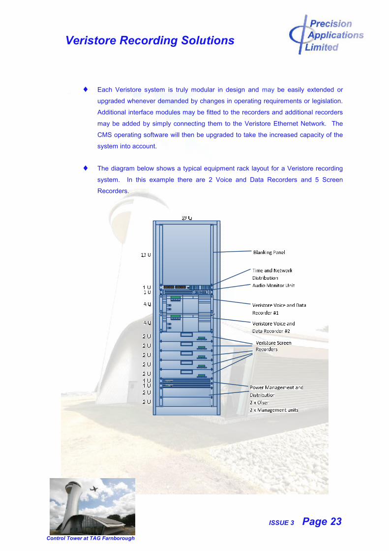
Each Veristore system is truly modular in design and may be easily extended or
upgraded whenever demanded by changes in operating requirements or legislation.
Additional interface modules may be fitted to the recorders and additional recorders
may be added by simply connecting them to the Veristore Ethernet Network. The
CMS operating software will then be upgraded to take the increased capacity of the
system into account.
The diagram below shows a typical equipment rack layout for a Veristore recording
system. In this example there are 2 Voice and Data Recorders and 5 Screen
Recorders.
Veristore Recording Solutions
ISSUE 3 Page 24
Control Tower at TAG Farnborough
4. Data Interfacing
4.1 Analogue Audio
The audio channels and ambient microphones are continuously recorded, 24/7,
with neither VOX nor AGC. Not only does this ensure that none of the information
is ever lost but also that periods of silence and low level signals are faithfully
recorded exactly as the controller heard them.
NOTE: Voice Activation can be the cause of data loss on account of
incorrectly set threshold levels.
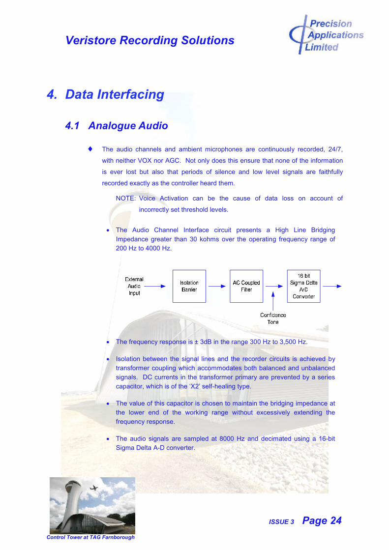
The Audio Channel Interface circuit presents a High Line Bridging
Impedance greater than 30 kohms over the operating frequency range of
200 Hz to 4000 Hz.
The frequency response is ± 3dB in the range 300 Hz to 3,500 Hz.
Isolation between the signal lines and the recorder circuits is achieved by
transformer coupling which accommodates both balanced and unbalanced
signals. DC currents in the transformer primary are prevented by a series
capacitor, which is of the ‘X2’ self-healing type.
The value of this capacitor is chosen to maintain the bridging impedance at
the lower end of the working range without excessively extending the
frequency response.
The audio signals are sampled at 8000 Hz and decimated using a 16-bit
Sigma Delta A-D converter.

Veristore Recording Solutions
ISSUE 3 Page 25
Control Tower at TAG Farnborough
4.2 Digital Audio
Digital audio signals are becoming more commonplace in the ATC environment
with the introduction of modern technology. It is perhaps more straightforward,
both in terms of interface circuits and storage capacity, to record audio signals in
the digital domain. However, Precision Applications recommend that the best
philosophy is to always record the signals that the controller actually heard, these
are, of course, in the analogue domain. Not only does this guarantee that the
information ‘heard by the controller’ is accurately recorded but also allows each
voice signal to be monitored for activity and alarms to be raised if faults are
detected.
In larger installations it may not be practical to record the all of the voice channels
in the analogue domain and in these circumstances Precision Applications are able
to offer Digital Audio Interface Modules for the Voice and Data recorder.
4.3 VoIP
VoIP technology is increasingly being introduced into modern communications
systems, including those used at airports for ATC. A number of standards, which
define the protocol for VoIP in ATM applications, have now been issued and
Precision Applications is able to offer a recording solution for VoIP recording to
comply with the standards.
4.4 Ambient Recording
Ambient Microphones may simply be considered as another audio input and
recorded using a standard analogue audio channel.
Precision Applications can supply Ambient Microphones and all of the necessary
interface equipment to provide a complete recording solution.
Veristore Recording Solutions
ISSUE 3 Page 26
Control Tower at TAG Farnborough
4.5 Through-the-Wall (Plot Extracted) Raw Radar Data
Raw (plot extracted) radar data, may be received as either synchronous HDLC
frames, via RS 232 / RS 422 on in IP format, via a LAN.
There are numerous different radar data formats, some of which are international
or national standards and some are specific to a particular radar manufacturer. A
number of these are readily recorded by the Voice and Data Recorder:
Asterix: A Eurocontrol Standard which is now supported by many of the
radar manufacturers.
RDIF: A UK format, similar to Asterix Category 001.
CAA: A UK CAA format.
Other formats can be accommodated and Precision Applications welcome
the opportunity to discuss specific customer requirements.
4.6 At-the-Glass (Screen Capture) Radar Data
The maximum screen resolutions that can be captured are 2048 x 2048
analogue (VGA or RGB), 2048 x 2048 digital (DVI) or 2560 x 1600 digital
(DVI-DL).
The maximum frame capture rate is 20 frames per second but a capture
rate of between 2 and 5 frames per second, with a limited compression
ratio, is recommended for the majority of ATC applications.. This provides
very high quality signal reproduction, which is indistinguishable from the
original screen display.
4.7 CCTV
The CCTV Recorder captures and records CCTV Camera signals either directly
from standard coax cables as PAL or NTSC signals or from a LAN as IP signals.
As in the case of the Screen Capture, Frame Capture Rates and Compression
Ratios can be selected to achieve the best quality recorded signal whilst
maintaining a reasonable storage capacity.
Veristore Recording Solutions
ISSUE 3 Page 27
Control Tower at TAG Farnborough
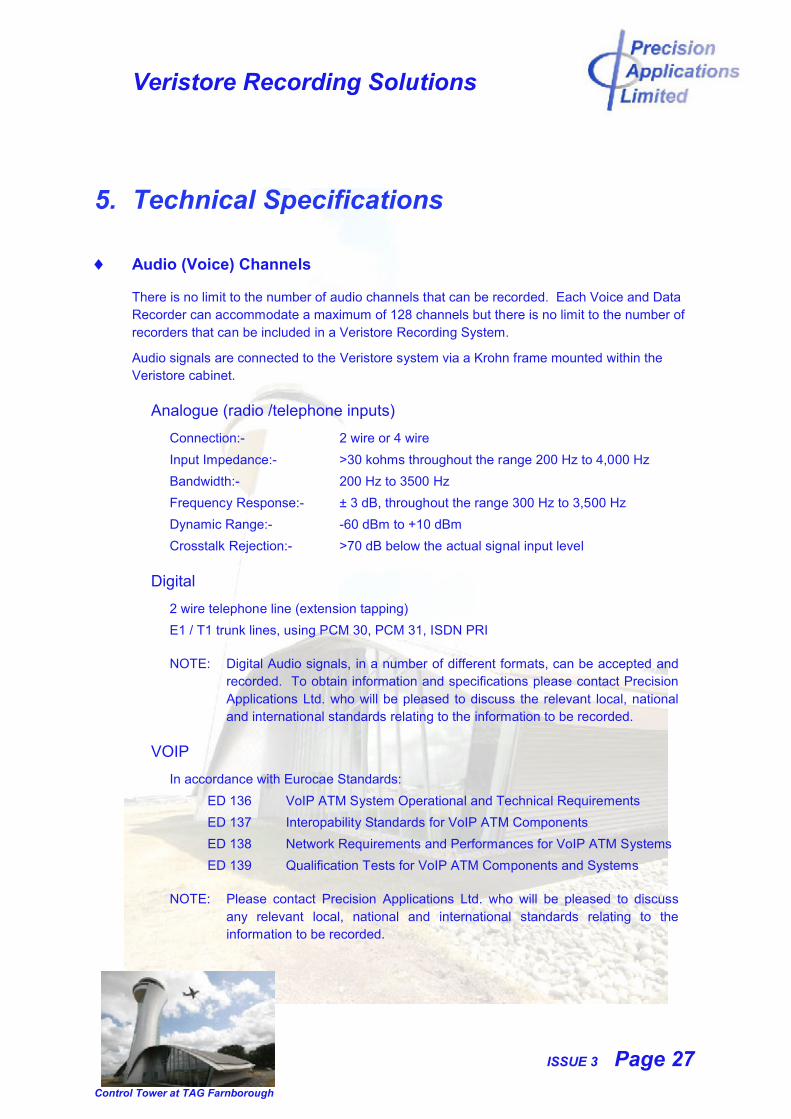
5. Technical Specifications
Audio (Voice) Channels
There is no limit to the number of audio channels that can be recorded. Each Voice and Data Recorder can accommodate a maximum of 128 channels but there is no limit to the number of recorders that can be included in a Veristore Recording System.
Audio signals are connected to the Veristore system via a Krohn frame mounted within the Veristore cabinet.
Analogue (radio /telephone inputs)
Connection:- 2 wire or 4 wire
Input Impedance:- >30 kohms throughout the range 200 Hz to 4,000 Hz
Bandwidth:- 200 Hz to 3500 Hz
Frequency Response:- ± 3 dB, throughout the range 300 Hz to 3,500 Hz
Dynamic Range:- -60 dBm to +10 dBm
Crosstalk Rejection:- >70 dB below the actual signal input level
Digital
2 wire telephone line (extension tapping)
E1 / T1 trunk lines, using PCM 30, PCM 31, ISDN PRI
NOTE: Digital Audio signals, in a number of different formats, can be accepted and recorded. To obtain information and specifications please contact Precision Applications Ltd. who will be pleased to discuss the relevant local, national and international standards relating to the information to be recorded.
VOIP
In accordance with Eurocae Standards:
ED 136 VoIP ATM System Operational and Technical Requirements
ED 137 Interopability Standards for VoIP ATM Components
ED 138 Network Requirements and Performances for VoIP ATM Systems
ED 139 Qualification Tests for VoIP ATM Components and Systems
NOTE: Please contact Precision Applications Ltd. who will be pleased to discuss any relevant local, national and international standards relating to the information to be recorded.
Veristore Recording Solutions
ISSUE 3 Page 28
Control Tower at TAG Farnborough
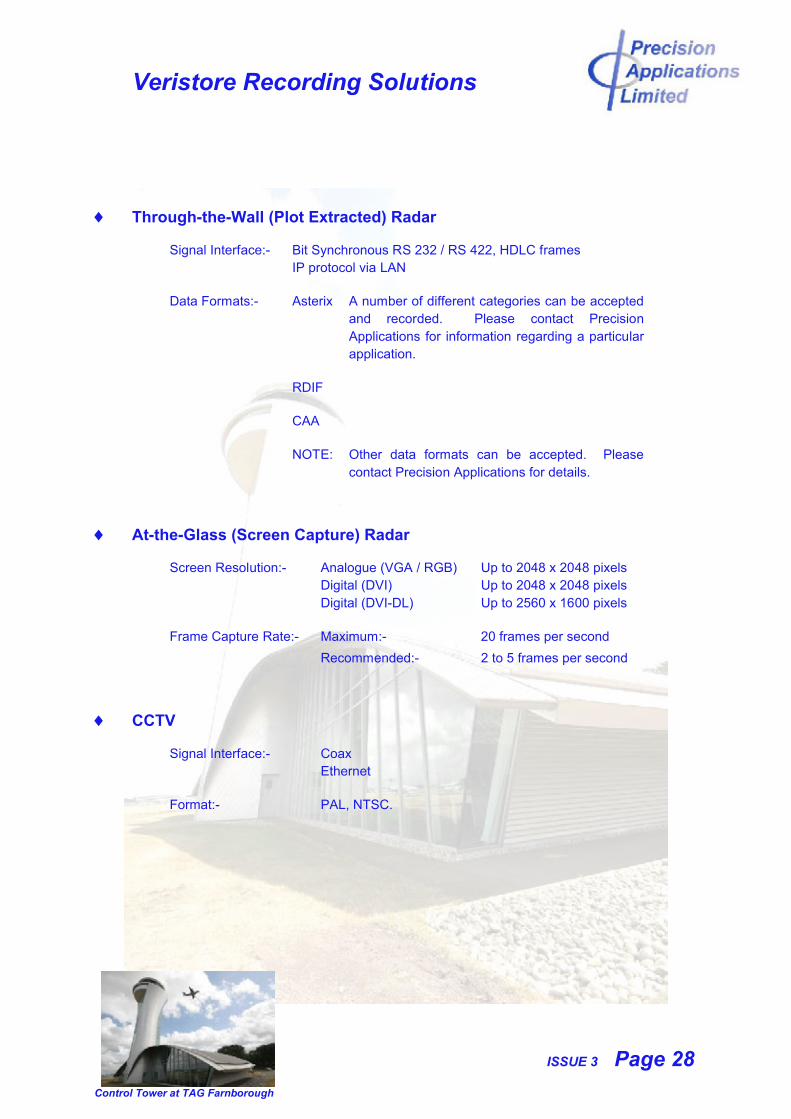
Through-the-Wall (Plot Extracted) Radar
Signal Interface:- Bit Synchronous RS 232 / RS 422, HDLC framesIP protocol via LAN
Data Formats:- Asterix A number of different categories can be accepted and recorded. Please contact Precision Applications for information regarding a particular application.
RDIF
CAA
NOTE: Other data formats can be accepted. Please contact Precision Applications for details.
At-the-Glass (Screen Capture) Radar
Screen Resolution:- Analogue (VGA / RGB) Up to 2048 x 2048 pixelsDigital (DVI) Up to 2048 x 2048 pixelsDigital (DVI-DL) Up to 2560 x 1600 pixels
Frame Capture Rate:- Maximum:- 20 frames per second
Recommended:- 2 to 5 frames per second
CCTV
Signal Interface:- CoaxEthernet
Format:- PAL, NTSC.
Veristore Recording Solutions
ISSUE 3 Page 29
Control Tower at TAG Farnborough
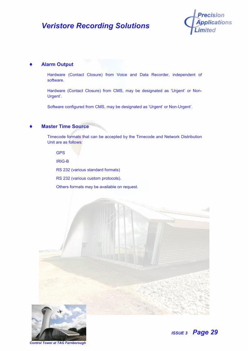
Alarm Output
Hardware (Contact Closure) from Voice and Data Recorder, independent of software.
Hardware (Contact Closure) from CMS, may be designated as ‘Urgent’ or Non-Urgent’.
Software configured from CMS, may be designated as ‘Urgent’ or Non-Urgent’.
Master Time Source
Timecode formats that can be accepted by the Timecode and Network DistributionUnit are as follows:
GPS
IRIG-B
RS 232 (various standard formats)
RS 232 (various custom protocols).
Others formats may be available on request.
Veristore Recording Solutions
ISSUE 3 Page 30
Control Tower at TAG Farnborough
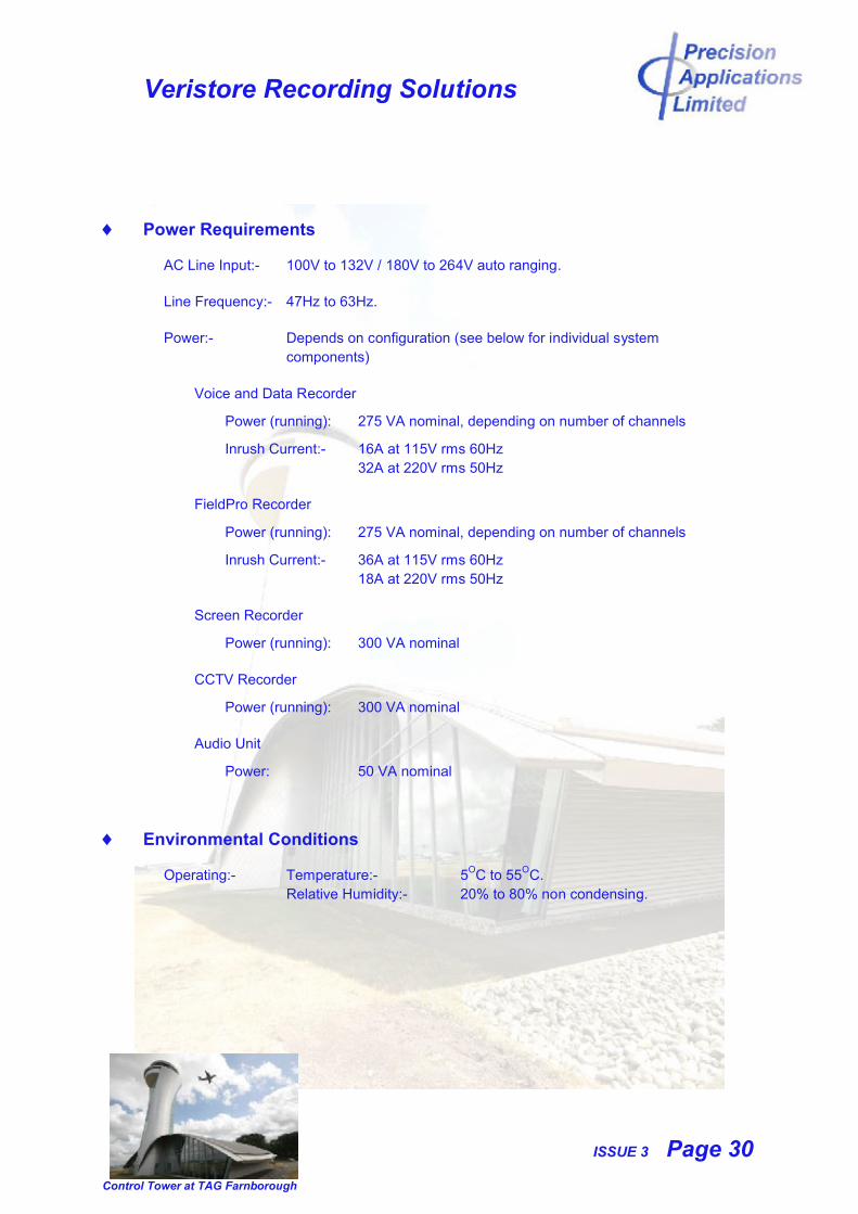
Power Requirements
AC Line Input:- 100V to 132V / 180V to 264V auto ranging.
Line Frequency:- 47Hz to 63Hz.
Power:- Depends on configuration (see below for individual system components)
Voice and Data Recorder
Power (running): 275 VA nominal, depending on number of channels
Inrush Current:- 16A at 115V rms 60Hz32A at 220V rms 50Hz
FieldPro Recorder
Power (running): 275 VA nominal, depending on number of channels
Inrush Current:- 36A at 115V rms 60Hz18A at 220V rms 50Hz
Screen Recorder
Power (running): 300 VA nominal
CCTV Recorder
Power (running): 300 VA nominal
Audio Unit
Power: 50 VA nominal
Environmental Conditions
Operating:- Temperature:- 5OC to 55OC.Relative Humidity:- 20% to 80% non condensing.
Veristore Recording Solutions
ISSUE 3 Page 31
Control Tower at TAG Farnborough
Dimensions and Weight
Veristore System mounted in a standard 19 inch equipment rack.
Voice and Data Recorder
Front Panel height:- 4U
Minimum rack depth:- 480 mm.
Maximum Weight:- 16 kg
FieldPro Recorder
Front Panel height:- 3U
Minimum rack depth:- 480 mm.
Maximum Weight:- 14 kg
Screen Recorder
Front Panel height:- 2U
Minimum rack depth:- 720 mm.
Maximum Weight:- 24 kg
CCTV Recorder
Front Panel height:- 2U
Minimum rack depth:- 720 mm.
Maximum Weight:- 24 kg
Audio Unit
Front Panel height:- 1U
Minimum rack depth:- 260 mm.
Maximum Weight:- 3 kg
Timecode and Network Distribution Unit
Front Panel height:- 1U
Minimum rack depth:- 260 mm.
Maximum Weight:- 3 kg
Veristore Recording Solutions
ISSUE 3 Page 32
Control Tower at TAG Farnborough
Warranty
1 year warranty and support covering parts, labour and software updates on all equipment.
5 year manufacturers warranty on Hard Disk Drives in the Voice and Data Recorders.
3 year manufacturers warranty on Hard Disk Drives in the Screen Recorders, CCTV Recorders, CMS and Remote Replay Station.
Maintenance Contracts
Maintenance Contracts, which may be tailored to individual customer requirements, are available for any duration between 1 and 10 years.
Support
Comprehensive technical support and training is offered during the installation and commissioning of the equipment and throughout its operational life.