vhf nav/com pilot’s guide for cessna nav iii
TRANSCRIPT

G1000TM
VHF NAV/COM pilot’s guide for Cessna Nav III

190-00389-01 Rev. AGarmin G1000 VHF NAV/COM Pilot’s Guide for Cessna Nav III
Record of Revisions
Revision Date of Revision Revision Page Range DescriptionA 11/24/04 4-1 – 4-23 Initial release.

190-00389-01 Rev. A Garmin G1000 VHF NAV/COM Pilot’s Guide for Cessna Nav III 4-1
INTRODUCTION
4.1 INTERFACE INTRODUCTION
OVERVIEW
On both the Primary Flight Display (PFD) and the Multi Function Display (MFD), the G1000 VHF NAV/COM window occupies the top portion of the panel. As shown in the figure below, the NAV-related controls, win-dows and fields are located on the left side, whereas the COM-related controls, windows and fields are located on the right side. The DME Tuning window is located to the right of the HSI on the PFD.
Figure 4.1.1 G1000 VHF NAV/COM Interface (PFD) DME Tuning Window
NAVControls
COMControlsNAV Frequency Window COM Frequency Window
This section provides information on the following as-pects of the G1000 VHF NAV/COM window:
• Windows and fields• Radio selection• Color code• Tuning box• Frequency Toggle Arrow• Radio status indications• Controls
NOTE: Information relative to the optional radios as well as the DME Tuning window is presented later in this document.

190-00389-01 Rev. AGarmin G1000 VHF NAV/COM Pilot’s Guide for Cessna Nav III4-2
INTRODUCTION
WINDOWS AND FIELDS
On both the PFD and the MFD, the NAV and COM Frequency windows are located at the top of the display on either side of the Navigation Status bar.
• The NAV Frequency window is displayed to the left of the Navigation Status bar.
• The COM Frequency window is displayed to the right of the Navigation Status bar.
Each radio frequency sub-window is composed of two (2) fields, a standby field and an active field.
• In the NAV Frequency window, the active frequency field is located on the right side, while the standby frequency field is located on the left side.
• In the COM Frequency window, the active frequency field is located on the left side, while the standby frequency field is located on the right side.
Standby NAVFrequency Field
Active NAVFrequency Field
Active COMFrequency Field
Standby COMFrequency Field
Figure 4.1.2 Frequency Fields
Selected NAVRadio Navigation Status Bar
Tuning BoxTuning Box
Selected COMRadio
RADIO SELECTION
Radio selection is performed as follows:
• NAV radio selection is performed via the CDI softkey located on the PFD:
- When NAV1 radio is selected, a single green arrow labeled either ‘VOR1’ or ‘LOC1’ is dis-played on the HSI.
- When NAV2 radio is selected, a double green arrow labeled either ‘VOR2’ or ‘LOC2’ is dis-played on the HSI.
• COM radio selection is performed via the COM1 MIC or COM2 MIC keys located on the audio panel:
- COM1 MIC key selects COM1 radio.
- COM2 MIC key selects COM2 radio.

190-00389-01 Rev. A Garmin G1000 VHF NAV/COM Pilot’s Guide for Cessna Nav III 4-3
INTRODUCTION
COLOR CODE
Frequencies located in the active field are displayed in either green or white.
• An active frequency that is displayed in green indicates that the corresponding radio is selected (i.e., in use) on the audio panel (COM) or on the HSI (NAV).
• An active frequency that is displayed in white indi-cates that the corresponding radio is not selected on the audio panel (COM) or on the HSI (NAV).
NOTE: In GPS mode, both active NAV frequencies are displayed in white.
Frequencies located in the standby field are displayed in white.
TUNING BOX
On both the PFD and the MFD, a cyan (i.e., light blue) tuning box appears around the standby frequency field and can be moved from one standby frequency field to another for the purpose of tuning or radio selection by pressing the dual COM or NAV knob.
Frequency Toggle Arrow Tuning Box
Figure 4.1.3 Frequency Toggle Arrow and Tuning Box
FREQUENCY TOGGLE ARROW
In both the COM and NAV windows, a Frequency Toggle Arrow appears next to the tuning box, between the active and standby frequencies. Pressing the dual COM or NAV knob toggles both the frequency tuning box and the Frequency Toggle Arrow between the radios.
NOTE: If the frequency tuning box is on a selected COM sub-window when a signal is transmitted for this radio, the Frequency Toggle Arrow is replaced by a TX indication.
NOTE: Pressing the Frequency Toggle key places the standby frequency into the active field, and vice versa.
RADIO STATUS INDICATIONS
• TX – When a COM radio is keyed, a white TX indication appears to the right of the correspond-ing COM frequency for the duration of the signal transmission.
• ID – When the Morse code identifier is ON for a NAV radio, a white ID indication appears to the left of the corresponding active NAV frequency and the Morse code identifier for this frequency can be heard if the corresponding NAV radio is selected on the audio panel.

190-00389-01 Rev. AGarmin G1000 VHF NAV/COM Pilot’s Guide for Cessna Nav III4-4
INTRODUCTION
CONTROLS
The NAV Frequency window is controlled by knobs and keys located to the left side of the display, while the COM Frequency window is controlled by knobs and keys located to the right side of the display.
The controls associated with the NAV window are as follows:
• A VOL/PUSH ID knob– Turn to adjust the NAV radio volume level.– Press to turn the Morse code identifier ON and
OFF.
• A Frequency Toggle key– Press to toggle the NAV frequencies between
the active and standby fields.
• A dual NAV knob– Turn to tune a NAV frequency in the NAV
tuning box (large knob for MHz; small knob for kHz).
– Press to toggle the NAV tuning box between the NAV radios.
Figure 4.1.4 NAV/COM Controls
Frequency Toggle Key
Dual NAV Knob
Dual COM Knob
VOL/PUSH ID Knob
VOL/PUSH SQ Knob
NAV Controls COM Controls
• Turn to tune in desired frequencies.
• Press to change tuning box positions.
The controls associated with the COM window are as follows:
• A VOL/PUSH SQ knob– Turn to adjust the COM radio volume level.– Press to turn automatic squelch ON and OFF.
• A Frequency Toggle key– Press to toggle the COM frequencies between
the active and standby fields.– Press and hold for approximately two (2) sec-
onds to tune the emergency frequency (121.500 MHz) automatically in the active COM field.
• A dual COM knob– Turn to tune a COM frequency in the COM
tuning box (large knob for MHz; small knob for kHz).
– Press to toggle the COM tuning box between the COM radios.

190-00389-01 Rev. A Garmin G1000 VHF NAV/COM Pilot’s Guide for Cessna Nav III 4-5
OPERATION – COM
4.2 COM FREQUENCY WINDOW
OVERVIEW
The G1000 COM radios can be tuned either over the 118.000 to 136.975 MHz frequency range with 25 kHz spacing selected or over the 118.000 to 136.990 MHz fre-quency range with 8.33 kHz spacing selected.
NOTE: COM channel spacing can be configured through the MFD, in the System Setup Page of the AUX Page group.
The Communications Frequency window is located to the right of the Navigation Status bar, provides the control and display of dual VHF Radio Communication Trans-ceivers (COM1 and COM2) and displays the following information:
• COM1 and COM2 active and standby frequencies
• Color-coded indication of the selected COM radio
• Indication of signal transmission
VOLUME
COM radio volume level can be adjusted from 0 to 100% of available volume (in increments of 3.25 percent-age points) using the VOL/PUSH SQ knob located above the COM Frequency Toggle key. Turning the VOL/PUSH SQ knob clockwise increases volume level for the COM radio on which the tuning box is placed, while turn-ing this knob counterclockwise decreases volume level for this COM radio.
When adjusting volume level for a COM radio, volume level is displayed in place of the corresponding standby COM frequency and the associated COM radio name (i.e., ‘COM1’ or ‘COM2’) is replaced by the term ‘VOLUME’. Volume level remains displayed in the COM Frequency window for a duration of two seconds after volume level is last changed.
Figure 4.2.1 COM Volume Level
AUTOMATIC SQUELCH
Automatic squelch provides maximum sensitivity to weaker signals while canceling most localized noise sourc-es. Automatic squelch can be disabled for a COM radio by pressing the COM knob to select the desired COM sub-window, then by pressing the VOL/PUSH SQ knob. When automatic squelch is disabled for a COM radio, COM audio remains continuously open.
NOTE: Pressing the VOL/PUSH SQ knob when automatic squelch is disabled reactivates the automatic squelch function.

190-00389-01 Rev. AGarmin G1000 VHF NAV/COM Pilot’s Guide for Cessna Nav III4-6
OPERATION – COM
SWITCHING THE TUNING BOX BETWEEN COM RADIOS
Pressing the dual COM knob toggles the frequency tuning box between the COM1 and COM2 fields.
NOTE: When a different COM MIC is selected on the audio panel, the frequency tuning box also moves on both the PFD and MFD.
Figure 4.2.2 Switching COM Radios
Pushing the dual COM knob switches the tuning box from one COM radio to the other.
MANUALLY TUNING A COM FREQUENCY
COM frequency manual tuning is performed by using the dual COM knob.
• The MHz (left) portion of the frequency can be tuned by turning the large COM knob.
• The kHz (right) portion of the frequency can be tuned by turning the small COM knob.
The frequency is tuned in the standby frequency field of the COM Frequency window. Turning either knob clockwise increases the tuned frequency. Conversely, turning either knob counterclockwise decreases the tuned frequency.
TOGGLING COM FREQUENCIES
Pressing the COM Frequency Toggle key toggles the COM frequencies between the active and standby fields of the COM radio on which the Frequency Toggle Arrow is located.
Figure 4.2.3 Toggling COM Frequencies
Pressing the COM Frequency Toggle key toggles the COM frequencies.
SELECTING A COM RADIO
The desired COM radio can be selected using the COM MIC keys located on the audio panel. When a COM MIC key is annunciated on the audio panel, the corresponding active COM frequency is displayed in green in the COM Frequency window.
Figure 4.2.4 Selecting a COM Radio
COM radio selection is performed via the audio
panel.
Top portion of the audio panel
NOTE: Please see the Audio Panel Pilot’s Guide for further details on the COM MIC keys.

190-00389-01 Rev. A Garmin G1000 VHF NAV/COM Pilot’s Guide for Cessna Nav III 4-7
OPERATION – COM
RADIO STATUS
When a COM radio is keyed, a white TX indication appears to the right of the active COM frequency to indi-cate that a transmission is in progress. The TX indication disappears once COM transmission is completed.
Figure 4.2.5 Radio Status Indications
NOTE: If a signal is transmitted on a COM radio for which frequency toggling is enabled (i.e., on which the tuning box is located), the Frequency Toggle Arrow disappears and is replaced by a TX indication.
EMERGENCY FREQUENCY (121.500 MHZ)
When a COM tuning failure is detected by the system, the emergency frequency (121.500 MHz) is automatically loaded into the active frequency field of the COM radio for which the tuning failure was detected.
Figure 4.2.6 COM Tuning Failure
NOTE: In the event of a dual display failure, the emergency frequency (121.500 MHz) automatically becomes available to the pilot through the pilot headset.
Quickly Tuning and Activating 121.500 MHz
Pressing and holding the COM Frequency Toggle key for approximately two (2) seconds automatically loads the emergency COM frequency (121.500 MHz) into the ac-tive frequency field of the COM radio for which frequency toggling is enabled.
Figure 4.2.7 Quickly Tuning 121.500 MHz
STUCK MICROPHONE
If the COM1 (or COM2) push-to-talk (PTT) switch be-comes stuck, or is accidentally left in the keyed position, or if a signal continues to be transmitted after the switch is released, the COM transmitter automatically times out (i.e., ceases to transmit) after 35 seconds of continuous transmitting, and an alert appears on the PFD to advise the crew of a stuck COM microphone (see figure below).
Figure 4.2.8 Stuck COM Microphone Alert

190-00389-01 Rev. AGarmin G1000 VHF NAV/COM Pilot’s Guide for Cessna Nav III4-8
OPERATION – COM
This page intentionally left blank.

190-00389-01 Rev. A Garmin G1000 VHF NAV/COM Pilot’s Guide for Cessna Nav III 4-9
OPERATION – NAV
4.3 NAV FREQUENCY WINDOW
OVERVIEW
The G1000 NAV radios can be tuned over the 108.00 to 117.95 MHz frequency range with 50 kHz spacing. The Navigation Frequency window is located to the left of the Navigation Status bar, provides the control and display of dual VOR/ILS receivers (NAV1 and NAV2) and displays the following information:
• NAV1 and NAV2 active and standby frequencies• NAV1 and NAV2 identifier indication (if the active
NAV frequency is a valid frequency and its Morse code identifier signal is received by the system).
• Color-coded indication of the selected NAV radio• Indication of the Morse code identifier status
VOLUME
NAV radio volume level can be adjusted from 0 to 100% of available volume (in increments of 3.25 percent-age points) using the VOL/PUSH ID knob located above the NAV Frequency Toggle key. Turning the VOL/PUSH ID knob clockwise increases volume level for the NAV radio on which the tuning box is placed, while turning this knob counterclockwise decreases volume level for this NAV radio. When adjusting volume level for a NAV radio, volume level is displayed in place of the corre-sponding standby NAV frequency and the associated NAV radio name (i.e., ‘NAV1’ or ‘NAV2’) is replaced by the term ‘VOLUME’. Volume level remains displayed in the NAV Frequency window for a duration of two seconds after volume level is last changed.
Figure 4.3.1 NAV Volume Level
MORSE CODE IDENTIFIER
Pressing the VOL/PUSH ID knob toggles the Morse code identifier ON and OFF for the active NAV frequency next to which the tuning box is located. When the Morse code identifier is ON, an ID indication appears to the left of the corresponding active NAV frequency.
Figure 4.3.2 ID Indication
The Morse code identifier is ON for the GHM VOR.
The Morse code identifier for an active NAV frequency can only be heard if the Morse code identifier for the cor-responding NAV radio is turned on (i.e., if the ID indica-tion appears next to the active NAV frequency) and if the corresponding NAV radio is selected on the audio panel (i.e., if the associated NAV radio annunciator light is il-luminated on the audio panel).
NAV portion of the audio
panel
Here, since NAV2 is the only NAV radio selected on the
audio panel, only the Morse code identifier for the GHM
VOR can be heard.
Figure 4.3.3 Morse Code Identifier Audio
NOTE: When a VOR signal is received, the VOR/LOC name identifier is displayed to the right of the corresponding active NAV frequency, regardless of the status of the Morse code identi-fier.
190-00389-01 Rev. AGarmin G1000 VHF NAV/COM Pilot’s Guide for Cessna Nav III4-10
OPERATION – NAV
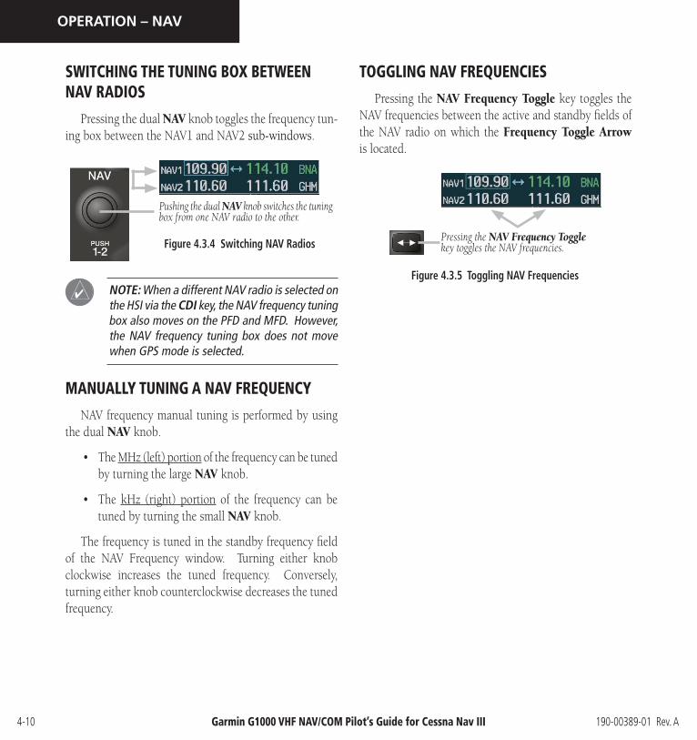
SWITCHING THE TUNING BOX BETWEEN NAV RADIOS
Pressing the dual NAV knob toggles the frequency tun-ing box between the NAV1 and NAV2 sub-windows.
Pushing the dual NAV knob switches the tuning box from one NAV radio to the other.
Figure 4.3.4 Switching NAV Radios
NOTE: When a different NAV radio is selected on the HSI via the CDI key, the NAV frequency tuning box also moves on the PFD and MFD. However, the NAV frequency tuning box does not move when GPS mode is selected.
MANUALLY TUNING A NAV FREQUENCY
NAV frequency manual tuning is performed by using the dual NAV knob.
• The MHz (left) portion of the frequency can be tuned by turning the large NAV knob.
• The kHz (right) portion of the frequency can be tuned by turning the small NAV knob.
The frequency is tuned in the standby frequency field of the NAV Frequency window. Turning either knob clockwise increases the tuned frequency. Conversely, turning either knob counterclockwise decreases the tuned frequency.
TOGGLING NAV FREQUENCIES
Pressing the NAV Frequency Toggle key toggles the NAV frequencies between the active and standby fields of the NAV radio on which the Frequency Toggle Arrow is located.
Figure 4.3.5 Toggling NAV Frequencies
Pressing the NAV Frequency Toggle key toggles the NAV frequencies.

190-00389-01 Rev. A Garmin G1000 VHF NAV/COM Pilot’s Guide for Cessna Nav III 4-11
OPERATION – NAV
SELECTING A NAV RADIO
The desired NAV radio can be selected using the CDI softkey located on the PFD. The three navigation modes that can be selected with the CDI softkey are as follows:
• VOR1 (or LOC1) – If NAV1 is selected as the NAV mode, a single green arrow labeled either ‘VOR1’ or ‘LOC1’ is displayed on the HSI and the active NAV1 frequency is displayed in green.
• VOR2 (or LOC2) – If NAV2 is selected as the NAV mode, a double green arrow labeled either ‘VOR2’ or ‘LOC2’ is displayed on the HSI and the active NAV2 frequency is displayed in green.
• GPS – If GPS mode is selected, a single magenta arrow appears on the HSI and neither NAV radio is selected.
NOTE: In GPS mode, both active NAV frequencies are displayed in white.
NOTE: When a VOR signal is received, the cor-responding VOR/LOC name identifier is displayed to the right of the associated active NAV fre-quency.
Figure 4.3.6 Selecting a NAV Radio
NAV radio selection is performed via the CDI
softkey.

190-00389-01 Rev. AGarmin G1000 VHF NAV/COM Pilot’s Guide for Cessna Nav III4-12
OPERATION – NAV
This page intentionally left blank.

190-00389-01 Rev. A Garmin G1000 VHF NAV/COM Pilot’s Guide for Cessna Nav III 4-13
OPERATION – NAV
4.4 OPTIONAL NAV RADIOS
OVERVIEW
Optionally, the G1000 system can support up to two (2) remotely-mounted Honeywell KN 63 DME transceiv-ers and up to two (2) panel-mounted Honeywell KR 87 ADF radios. The Honeywell KN 63 is a 200-channel, 100-watt, all-solid-state digital DME transceiver that pro-vides distance information to the G1000 system.
NOTE: Operational information relative to the optional Honeywell KR 87 ADF radio can be found in the Honeywell Silver Crown Plus™ Avionics Systems Pilot’s Guide.
DME TUNING WINDOW
Tuning of the DME radio is performed via the DME Tuning window. The DME Tuning window is an Auxiliary window that is located to the right of the HSI on the PFD. Pressing the top-level DME softkey toggles the DME Tun-ing window ON and OFF.
NOTE: When another Auxiliary window is turned on, the DME Tuning window is removed from the PFD.
Figure 4.4.1 DME Tuning Window
DME Modes
Selecting the DME Transceiver Tuning Mode
The following DME transceiver tuning modes can be selected:
• NAV1 – Tunes the DME frequency from the selected NAV1 frequency.
• NAV2 – Tunes the DME frequency from the selected NAV2 frequency.
• HOLD – When transitioning from NAV1 or NAV2 mode to HOLD mode, the DME frequency remains set to the last selected NAV frequency.
To select a DME transceiver tuning mode:
1. Turn the small FMS knob to select the desired DME tuning mode.
2. Press the ENT key to validate the selection.
NOTE: Pressing the CLR key while in the process of selecting DME tuning mode causes the system to cancel data entry and revert back to the previ-ously selected DME tuning mode.
NOTE: Pressing the FMS knob activates/deacti-vates the cursor in the DME Tuning window.
NOTE: Please refer to the Primary Flight Display Pilot’s Guide for information on the DME Informa-tion window.

190-00389-01 Rev. AGarmin G1000 VHF NAV/COM Pilot’s Guide for Cessna Nav III4-14
OPERATION – NAV
This page intentionally left blank.
190-00389-01 Rev. A Garmin G1000 VHF NAV/COM Pilot’s Guide for Cessna Nav III 4-15
OPERATION – AUTO-TUNING
4.5 FREQUENCY AUTO-TUNING
OVERVIEW
The G1000 system offers multiple auto-tuning capabil-ities that help reduce cockpit workload. The PFD allows for the auto-tuning of COM frequencies associated with the nearest airports, while the MFD provides auto-tuning of both COM and NAV frequencies from various pages. In addition, regardless of the display, the pertinent primary NAV frequency is entered automatically in the NAV win-dow upon approach loading or approach activation.
In brief, frequencies can be automatically loaded into their respective frequency windows in the following ways:
• By using the ENT key when the frequency is high-lighted on the appropriate page (PFD and MFD).
• Upon loading or activating an approach (PFD and MFD).
NOTE: Turn the FMS knob to scroll through a list of frequencies.
Press the ENT key to load a highlighted fre-
quency into the associated frequency window.
Turn the FMS knob to scroll through a list of frequencies.
Figure 4.5.1 Loading Frequencies
AUTO-TUNING ON THE PFD
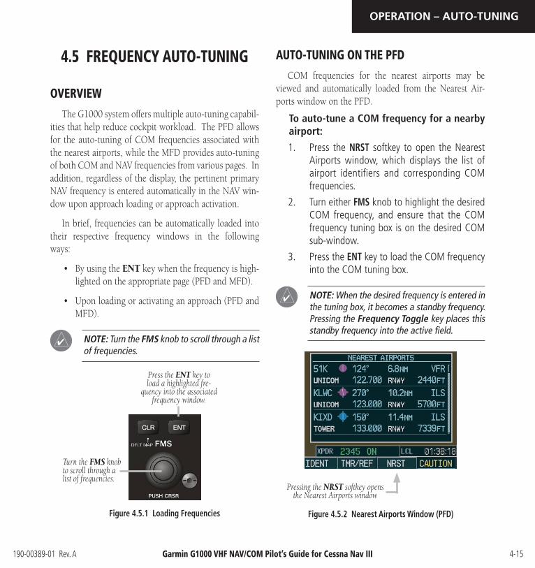
COM frequencies for the nearest airports may be viewed and automatically loaded from the Nearest Air-ports window on the PFD.
To auto-tune a COM frequency for a nearby airport:
1. Press the NRST softkey to open the Nearest Airports window, which displays the list of airport identifiers and corresponding COM frequencies.
2. Turn either FMS knob to highlight the desired COM frequency, and ensure that the COM frequency tuning box is on the desired COM sub-window.
3. Press the ENT key to load the COM frequency into the COM tuning box.
NOTE: When the desired frequency is entered in the tuning box, it becomes a standby frequency. Pressing the Frequency Toggle key places this standby frequency into the active field.
Figure 4.5.2 Nearest Airports Window (PFD)
Pressing the NRST softkey opens the Nearest Airports window

190-00389-01 Rev. AGarmin G1000 VHF NAV/COM Pilot’s Guide for Cessna Nav III4-16
OPERATION – AUTO-TUNING
AUTO-TUNING ON THE MFD
Frequencies can be selected and loaded from the fol-lowing MFD pages:
• WPT – Airport Information
• WPT – VOR Information
• NRST – Nearest Airports
• NRST – Nearest VOR
• NRST – Nearest Frequencies
Figure 4.5.3 MFD Page Group Icon
NOTE: In NAV mode, upon any VOR/ILS approach activation, the appropriate NAV frequency is automatically loaded into the standby field of the selected NAV radio, regardless of the cur-rent MFD page that is displayed.
NOTE: In GPS mode, upon any VOR/ILS approach activation, the appropriate NAV frequency is automatically loaded into the active field of NAV1, regardless of the current MFD page that is displayed.
WPT – Airport Information Page
The Airport Information Page displays runway infor-mation and a list of frequencies for the selected airport identifier as well as departure, arrival and approach in-formation.
To display the entire list of frequencies for a desired airport:
1. On the Airport Information Page, press the INFO softkey to display runway and frequency information for a specific airport.
2. Press the FMS knob to activate the selection cursor in the window.
3. Turn the FMS knob to select the desired airport identifier and press the ENT key. A list of all available frequencies for the selected airport appears.
Figure 4.5.4 WPT – Airport Information Page (INFO)

190-00389-01 Rev. A Garmin G1000 VHF NAV/COM Pilot’s Guide for Cessna Nav III 4-17
OPERATION – AUTO-TUNING
To load the desired COM frequency into the COM tuning box:
1. When the list of frequencies for the selected airport is displayed, highlight the desired fre-quency by turning the large FMS knob.
2. Press the ENT key.
NOTE: The runway Pilot Controlled Lighting (PCL) frequency (located in the Runways box of the INFO portion of the Airport Information Page) may also be highlighted with the large FMS knob and loaded into the COM tuning box by pressing the ENT key.
Figure 4.5.5 WPT – Airport Information Page (APR)
To load the primary approach NAV frequency into the NAV tuning box:
1 On the Airport Information Page, press the APR softkey to display approach information for a specific airport.
2. Press the FMS knob to activate the selection cursor in the window.
3. Turn the large FMS knob to highlight the primary NAV frequency located in the Primary Frequency box.
4. Press the ENT key.

190-00389-01 Rev. AGarmin G1000 VHF NAV/COM Pilot’s Guide for Cessna Nav III4-18
OPERATION – AUTO-TUNING
WPT – VOR Information Page
The VOR Information Page displays information spe-cific to individual VORs, including the airport that is near-est to the selected VOR.
To load a VOR frequency into the NAV window:
1. On the VOR Information Page, press the FMS knob to activate the VOR Information window.
2. Turn the FMS knob as needed to select the desired VOR and press the ENT key to validate the selection.
3. Turn the large FMS knob to highlight the VOR frequency and press the ENT key to load this frequency into the tuning box of the NAV Frequency window.
Figure 4.5.6 WPT – VOR Information Page
NOTE: If the MENU key is pressed when on the VOR Information Page, the ‘View Recent VOR List’ menu option is displayed for quick access to recently used VORs. However, if no VOR frequen-cies have been tuned, this menu option is grayed out.

190-00389-01 Rev. A Garmin G1000 VHF NAV/COM Pilot’s Guide for Cessna Nav III 4-19
OPERATION – AUTO-TUNING
NRST – Nearest Airports Page
The Nearest Airports Page displays a list of the nearest airports as well as related runway, frequency and approach information. On this page, any frequency associated with the selected airport can be loaded into the NAV or COM Frequency window.
To display the entire list of frequencies for a nearby airport and load a frequency from that list:
1. On the Nearest Airports Page, press the FMS knob to activate the selection cursor in the Nearest Airports window.
2. Turn the FMS knob to scroll through the list of nearest airport identifiers until the desired nearest airport is highlighted.
3. Press the FREQ softkey to activate the selection cursor in the Frequencies box.
4. Turn the FMS knob to scroll through the list of frequencies for the selected airport.
5. When the desired frequency is highlighted, press the ENT key to load this frequency into the tuning box of the appropriate Frequency window (NAV or COM).
Figure 4.5.7 NRST – Nearest Airport Page

190-00389-01 Rev. AGarmin G1000 VHF NAV/COM Pilot’s Guide for Cessna Nav III4-20
OPERATION – AUTO-TUNING
NRST – Nearest VOR Page
The Nearest VOR Page displays a list of the nearest VORs together with related information, including the as-sociated VOR frequency.
To load a VOR frequency into the NAV window:
1. On the Nearest VOR Page, press the FMS knob to activate the Nearest VOR window.
2. Turn the FMS knob to scroll through the list of nearest VORs until the desired nearest VOR is highlighted.
3. Press the FREQ softkey to activate the selection cursor in the Frequency box and press the ENT key to load the frequency into the tuning box of the NAV Frequency window.
Figure 4.5.8 NRST – Nearest VOR Page

190-00389-01 Rev. A Garmin G1000 VHF NAV/COM Pilot’s Guide for Cessna Nav III 4-21
OPERATION – AUTO-TUNING
NRST – Nearest Frequencies Page
The Nearest Frequencies Page displays a list of nearest ARTCC, FSS and WX frequencies. For the purpose of fre-quency selection, the selection cursor can be activated on the ARTCC, FSS, or WX windows by using the ARTCC, FSS and WX softkeys, respectively.
To view a nearest ARTCC frequency and load it into the standby frequency field:
1. Press the ARTCC softkey to activate the selec-tion cursor in the Nearest ARTCC window.
2. Turn the small FMS knob to scroll through the list of ARTCC names, then the large FMS knob to highlight the desired ARTCC frequency.
3. Press the ENT key to load the desired ARTCC frequency into the tuning box.
NOTE: The Nearest ARTCC window contains a numbered list of ARTCC names as well as associ-ated bearing and distance information.
To view a nearest FSS frequency and load it into the standby frequency field:
1. Press the FSS softkey to activate the selection cursor in the Nearest FSS window.
2. Turn the small FMS knob to scroll through the list of FSS names, then the large FMS knob to highlight the desired FSS frequency.
3. Press the ENT key to load the desired FSS frequency into the tuning box.
NOTE: The Nearest FSS window contains a numbered list of FSS names as well as associated bearing and distance information.
To view a nearest WX frequency and load it into the standby frequency field:
1. Press the WX softkey to activate the selection cursor in the Nearest WX window.
2. Turn the FMS knob to highlight the desired WX frequency.
3. Press the ENT key to load the desired WX fre-quency into the tuning box.
Figure 4.5.9 NRST – Nearest Frequencies Page

190-00389-01 Rev. AGarmin G1000 VHF NAV/COM Pilot’s Guide for Cessna Nav III4-22
OPERATION – AUTO-TUNING
AUTO-TUNING UPON APPROACH ACTIVATION (NAV FREQUENCIES)
NAV frequencies can be automatically loaded into the NAV Frequency window upon approach activation, re-gardless of the display unit being used.
NOTE: The primary NAV frequency also becomes auto-tuned upon loading of an approach.
To auto-tune a NAV frequency if the desired approach is not already loaded:
1. Press the PROC key to open the Procedures window.
2. Turn the large FMS knob to highlight the ‘SELECT APPROACH’ menu option and press the ENT key.
3. Use both the FMS knob and the ENT key as needed to select the desired airport, VOR/ILS approach and transition.
4. Turn the large FMS knob to highlight either the ‘LOAD?’ or ‘ACTIVATE?’ prompt and press the ENT key. The primary NAV frequency for the activated approach becomes loaded into the standby field of the selected NAV radio.
Figure 4.5.10 Selecting an Approach
Figure 4.5.11 Loading an Approach

190-00389-01 Rev. A Garmin G1000 VHF NAV/COM Pilot’s Guide for Cessna Nav III 4-23
OPERATION – AUTO-TUNING
To auto-tune a NAV frequency if the desired approach is already loaded:
1. Press the PROC key to open the Procedures window.
2. Turn the large FMS knob to highlight the ‘ACTIVATE APPROACH’ menu option and press the ENT key. The approach primary NAV frequency becomes automatically loaded into the standby field of the selected NAV radio.
NOTE: If the system is in GPS mode when a VOR/ILS approach is loaded or activated, the approach primary NAV frequency is automatically loaded into the active field of NAV1.
NOTE: Before loading or activating an approach, the associated primary NAV frequency may be loaded into the NAV tuning box by highlighting the frequency in the Select Approach window via the FMS knob, then by pressing the ENT key.
NOTE: Automatic loading of the NAV frequency also occurs upon vector-to-final activation, if the NAV frequency is not already loaded into either the standby or the active field of the selected NAV radio.
NOTE: Approach activation can also be performed via the MENU key when the Flight Plan window is open.
Figure 4.5.12 Activating an Approach
NOTE: When a VOR/ILS approach has been acti-vated in GPS mode, if the ILS CDI Capture option on the AUX 4 Page is set to AUTO, the system automatically switches to NAV mode as the final approach course is intercepted (if within 15 nm from the FAF). Please see the Multi Function Display Pilot’s Guide for details on this feature.

Garmin International, Inc. 1200 East 151st Street Olathe, KS 66062, U.S.A. p: 913.397.8200 f: 913.397.8282
Garmin AT, Inc.2345 Turner Road SESalem, OR 97302, U.S.A.p: 503.391.3411 f: 503.364.2138
Garmin (Europe) Ltd.Unit 5, The QuadrangleAbbey Park Industrial EstateRomsey, SO51 9DL, U.K.p: 44/0870.8501241 f: 44/0870.8501251
Garmin CorporationNo. 68, Jangshu 2nd RoadShijr, Taipei County, Taiwanp: 886/2.2642.9199 f: 886/2.2642.9099
www.garmin.com
190-00389-01 Rev. A © 2004 Garmin Ltd. or its subsidiaries