vi800a relay sample application - ftdi chip home page€¦ · · 2016-07-25an_331 vi800a relay...
TRANSCRIPT
Use of FTDI devices in life support and/or safety applications is entirely at the user’s risk, and the user agrees to defend, indemnify and hold FTDI harmless from any and all damages, claims, suits
or expense resulting from such use.
Future Technology Devices International Limited (FTDI) Unit 1, 2 Seaward Place, Glasgow G41 1HH, United Kingdom Tel.: +44 (0) 141 429 2777 Fax: + 44 (0) 141 429 2758
Web Site: http://ftdichip.com
Copyright © 2014 Future Technology Devices International Limited
Application Note
AN_331
VI800A Relay
Sample Application
Version 1.0
Issue Date: 2014-10-23
This document introduces a sample application to demonstrate the VI800A-RELAY
module. This accessory module connects to the VM800P series of boards and
provides four relay outputs along with four logic inputs.
Application Note
AN_331 VI800A Relay Sample Application Version 1.0
Document Reference No.: FT_001059 Clearance No.: FTDI#418
2 Product Page Document Feedback Copyright © 2014 Future Technology Devices International Limited
Table of Contents
1 Introduction .................................................................... 3
1.1 Audience ................................................................................... 3
1.2 Scope ........................................................................................ 3
2 Overview ......................................................................... 4
2.1 Hardware .................................................................................. 4
2.2 Architecture .............................................................................. 4
2.3 Hardware requirement .............................................................. 5
2.4 Software requirement ............................................................... 5
3 Software Package Introduction ....................................... 6
3.1 Library Folder Structure ............................................................ 6
3.2 FT_VI800A_RELAY class ............................................................ 7
4 Setup steps ..................................................................... 8
4.1 Preparing Hardware .................................................................. 8
4.2 Arduino Library based SampleApp - Source code upload ......... 10
4.2.1 Install Library .......................................................................................... 10
4.2.2 Source Code Upload ................................................................................. 12
5 Sample Application Flowchart ....................................... 15
6 Sample Application ....................................................... 16
6.1 Platform Setup ........................................................................ 16
6.2 Functionality ........................................................................... 17
7 Application execution .................................................... 18
8 Contact Information ...................................................... 24
Appendix A– References .................................................... 25
Document References ...................................................................... 25
Acronyms and Abbreviations ........................................................... 25
Appendix B – List of Tables & Figures ................................ 26
List of Tables ................................................................................... 26
List of Figures .................................................................................. 26
9 Appendix C– Revision History ....................................... 27
10 Internal Revision History .............................................. 28
Application Note
AN_331 VI800A Relay Sample Application Version 1.0
Document Reference No.: FT_001059 Clearance No.: FTDI#418
3 Product Page Document Feedback Copyright © 2014 Future Technology Devices International Limited
1 Introduction
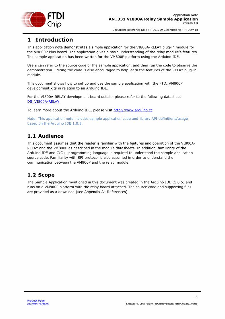
This application note demonstrates a simple application for the VI800A-RELAY plug-in module for
the VM800P Plus board. The application gives a basic understanding of the relay module’s features.
The sample application has been written for the VM800P platform using the Arduino IDE.
Users can refer to the source code of the sample application, and then run the code to observe the
demonstration. Editing the code is also encouraged to help learn the features of the RELAY plug-in
module.
This document shows how to set up and use the sample application with the FTDI VM800P
development kits in relation to an Arduino IDE.
For the VI800A-RELAY development board details, please refer to the following datasheet
DS_VI800A-RELAY
To learn more about the Arduino IDE, please visit http://www.arduino.cc
Note: This application note includes sample application code and library API definitions/usage
based on the Arduino IDE 1.0.5.
1.1 Audience
This document assumes that the reader is familiar with the features and operation of the VI800A-
RELAY and the VM800P as described in the module datasheets. In addition, familiarity of the
Arduino IDE and C/C++programming language is required to understand the sample application
source code. Familiarity with SPI protocol is also assumed in order to understand the
communication between the VM800P and the relay module.
1.2 Scope
The Sample Application mentioned in this document was created in the Arduino IDE (1.0.5) and
runs on a VM800P platform with the relay board attached. The source code and supporting files
are provided as a download (see Appendix A– References).
Application Note
AN_331 VI800A Relay Sample Application Version 1.0
Document Reference No.: FT_001059 Clearance No.: FTDI#418
4 Product Page Document Feedback Copyright © 2014 Future Technology Devices International Limited
2 Overview
2.1 Hardware
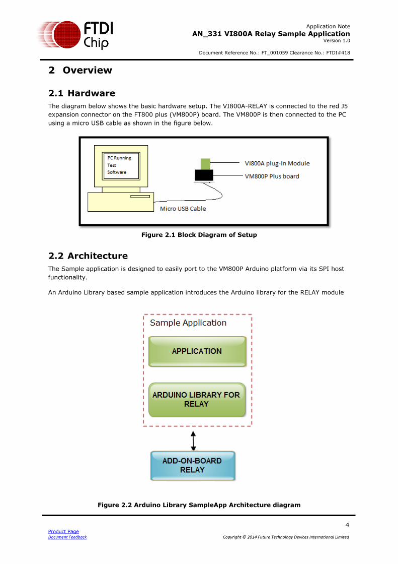
The diagram below shows the basic hardware setup. The VI800A-RELAY is connected to the red J5
expansion connector on the FT800 plus (VM800P) board. The VM800P is then connected to the PC
using a micro USB cable as shown in the figure below.
Figure 2.1 Block Diagram of Setup
2.2 Architecture
The Sample application is designed to easily port to the VM800P Arduino platform via its SPI host
functionality.
An Arduino Library based sample application introduces the Arduino library for the RELAY module
Figure 2.2 Arduino Library SampleApp Architecture diagram
Application Note
AN_331 VI800A Relay Sample Application Version 1.0
Document Reference No.: FT_001059 Clearance No.: FTDI#418
5 Product Page Document Feedback Copyright © 2014 Future Technology Devices International Limited
2.3 Hardware requirement
The following items are required in order to use the demonstration code
VI800A-RELAY Module x 1
FTDI FT800 Plus Board (VM800P) x 1
Micro USB cable to connect VM800P to PC x 1
PC (Windows operating system)
FTDI UART cable which will give 5V and GND connections x 2 (see note) Note: As described in a later section, the demonstration code uses two FTDI USB-UART (TTL) cables to supply 5V to the relay contacts as these cables are also used in the demonstration code for other VM800P plug-in modules which feature serial-style interfaces. Other 5V power sources could be used instead.
2.4 Software requirement
Arduino IDE 1.0.5 and later
VI800A_RELAY Arduino Library Sample Application release package (see Appendix A– References).
Application Note
AN_331 VI800A Relay Sample Application Version 1.0
Document Reference No.: FT_001059 Clearance No.: FTDI#418
6 Product Page Document Feedback Copyright © 2014 Future Technology Devices International Limited
3 Software Package Introduction
This section describes the software package provided for the sample application, which consists of
the Arduino library and the demo application.
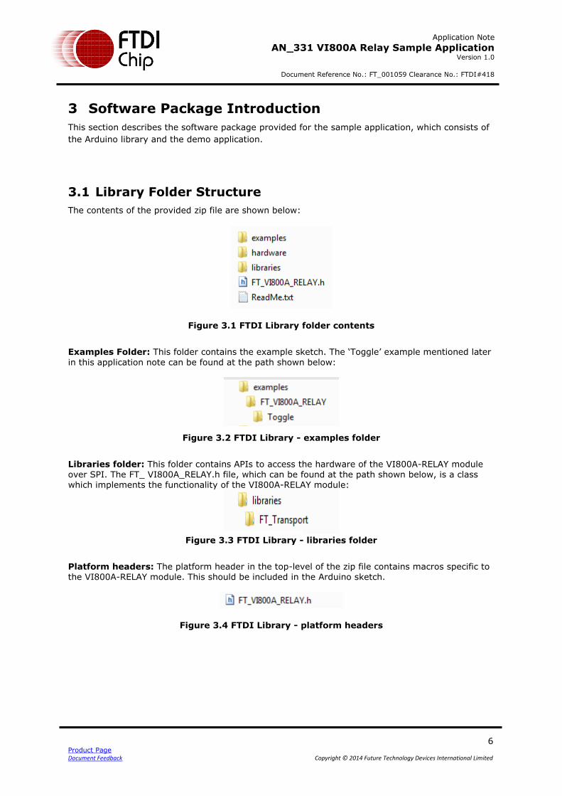
3.1 Library Folder Structure
The contents of the provided zip file are shown below:
Figure 3.1 FTDI Library folder contents
Examples Folder: This folder contains the example sketch. The ‘Toggle’ example mentioned later
in this application note can be found at the path shown below:
Figure 3.2 FTDI Library - examples folder
Libraries folder: This folder contains APIs to access the hardware of the VI800A-RELAY module over SPI. The FT_ VI800A_RELAY.h file, which can be found at the path shown below, is a class which implements the functionality of the VI800A-RELAY module:
Figure 3.3 FTDI Library - libraries folder
Platform headers: The platform header in the top-level of the zip file contains macros specific to the VI800A-RELAY module. This should be included in the Arduino sketch.
Figure 3.4 FTDI Library - platform headers
Application Note
AN_331 VI800A Relay Sample Application Version 1.0
Document Reference No.: FT_001059 Clearance No.: FTDI#418
7 Product Page Document Feedback Copyright © 2014 Future Technology Devices International Limited
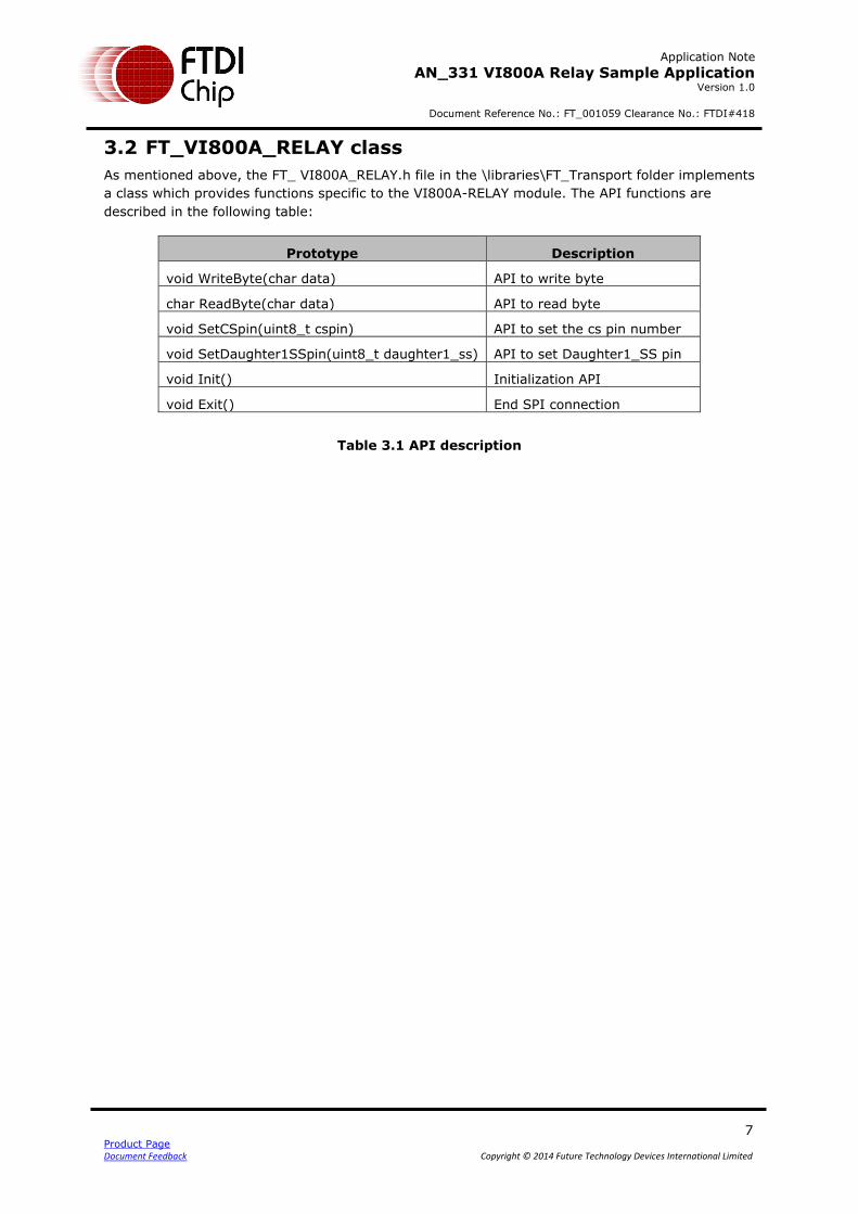
3.2 FT_VI800A_RELAY class
As mentioned above, the FT_ VI800A_RELAY.h file in the \libraries\FT_Transport folder implements
a class which provides functions specific to the VI800A-RELAY module. The API functions are
described in the following table:
Prototype Description
void WriteByte(char data) API to write byte
char ReadByte(char data) API to read byte
void SetCSpin(uint8_t cspin) API to set the cs pin number
void SetDaughter1SSpin(uint8_t daughter1_ss) API to set Daughter1_SS pin
void Init() Initialization API
void Exit() End SPI connection
Table 3.1 API description
Application Note
AN_331 VI800A Relay Sample Application Version 1.0
Document Reference No.: FT_001059 Clearance No.: FTDI#418
8 Product Page Document Feedback Copyright © 2014 Future Technology Devices International Limited
4 Setup steps
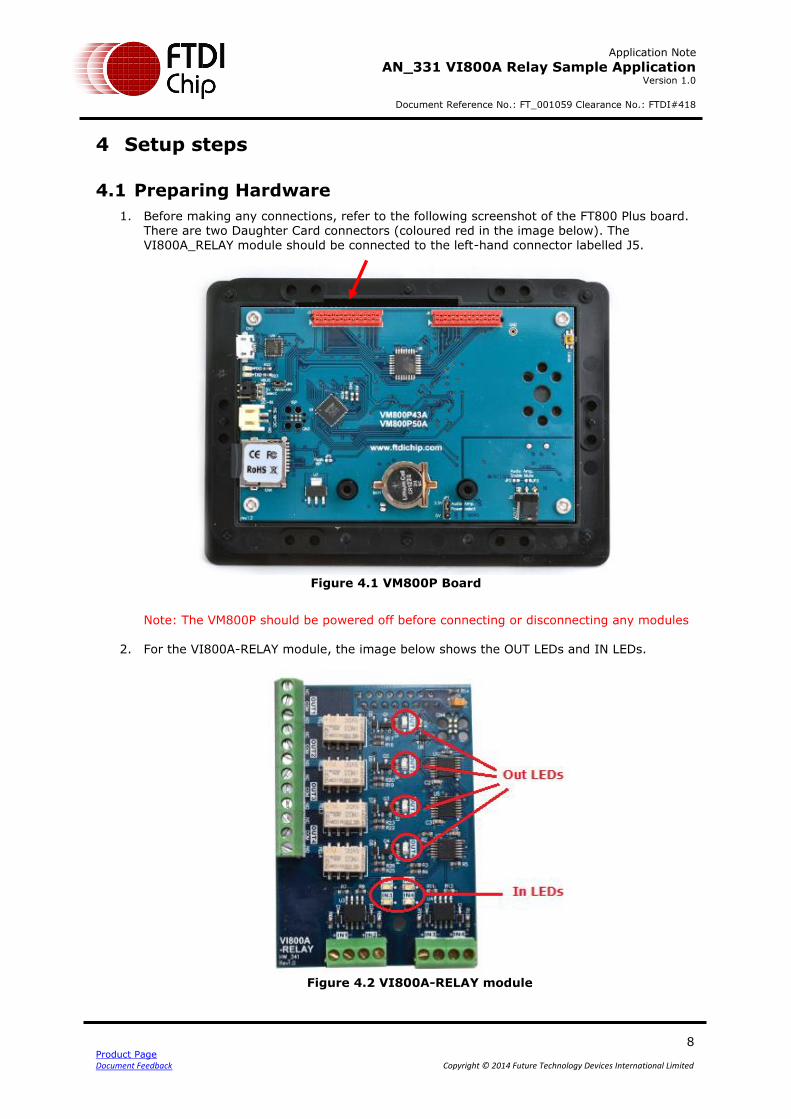
4.1 Preparing Hardware
1. Before making any connections, refer to the following screenshot of the FT800 Plus board. There are two Daughter Card connectors (coloured red in the image below). The VI800A_RELAY module should be connected to the left-hand connector labelled J5.
Figure 4.1 VM800P Board
Note: The VM800P should be powered off before connecting or disconnecting any modules
2. For the VI800A-RELAY module, the image below shows the OUT LEDs and IN LEDs.
Figure 4.2 VI800A-RELAY module
Application Note
AN_331 VI800A Relay Sample Application Version 1.0
Document Reference No.: FT_001059 Clearance No.: FTDI#418
9 Product Page Document Feedback Copyright © 2014 Future Technology Devices International Limited
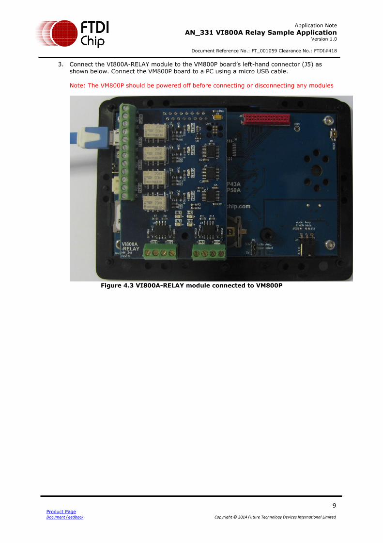
3. Connect the VI800A-RELAY module to the VM800P board’s left-hand connector (J5) as shown below. Connect the VM800P board to a PC using a micro USB cable.
Note: The VM800P should be powered off before connecting or disconnecting any modules
Figure 4.3 VI800A-RELAY module connected to VM800P
Application Note
AN_331 VI800A Relay Sample Application Version 1.0
Document Reference No.: FT_001059 Clearance No.: FTDI#418
10 Product Page Document Feedback Copyright © 2014 Future Technology Devices International Limited
4.2 Arduino Library based SampleApp - Source code upload
To use the sample application, the first step is to install the Arduino Library. Refer to the section below
to install the Arduino library for the VI800A-RELAY.
4.2.1 Install Library
4.2.1.1 Another FTDI Library Is Present
If there is an existing FTDI library in the library folder, simply extract the library files and put the
new files/folders into their respective location in the existing library directory.
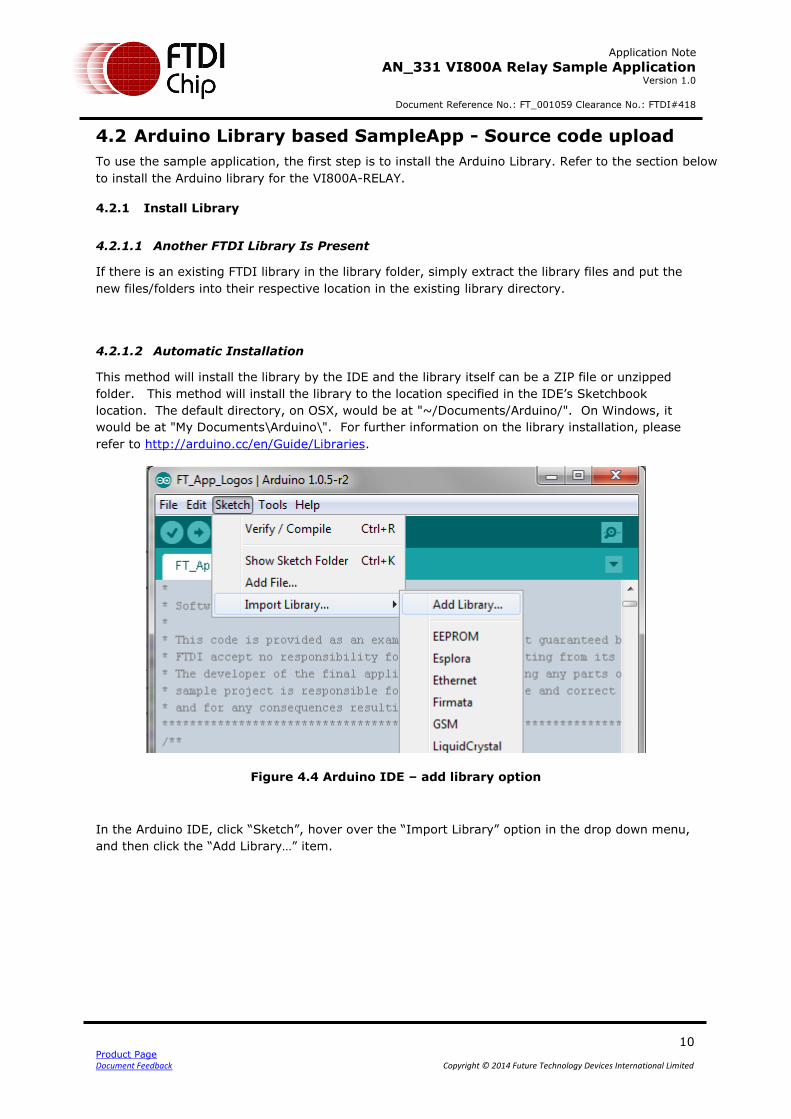
4.2.1.2 Automatic Installation
This method will install the library by the IDE and the library itself can be a ZIP file or unzipped
folder. This method will install the library to the location specified in the IDE’s Sketchbook
location. The default directory, on OSX, would be at "~/Documents/Arduino/". On Windows, it
would be at "My Documents\Arduino\". For further information on the library installation, please
refer to http://arduino.cc/en/Guide/Libraries.
Figure 4.4 Arduino IDE – add library option
In the Arduino IDE, click “Sketch”, hover over the “Import Library” option in the drop down menu,
and then click the “Add Library…” item.
Application Note
AN_331 VI800A Relay Sample Application Version 1.0
Document Reference No.: FT_001059 Clearance No.: FTDI#418
11 Product Page Document Feedback Copyright © 2014 Future Technology Devices International Limited
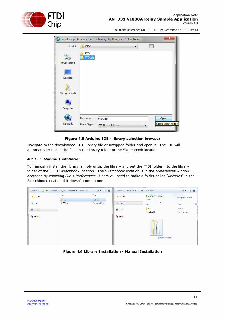
Figure 4.5 Arduino IDE - library selection browser
Navigate to the downloaded FTDI library file or unzipped folder and open it. The IDE will
automatically install the files to the library folder of the Sketchbook location.
4.2.1.3 Manual Installation
To manually install the library, simply unzip the library and put the FTDI folder into the library
folder of the IDE's Sketchbook location. The Sketchbook location is in the preferences window
accessed by choosing File->Preferences. Users will need to make a folder called “libraries” in the
Sketchbook location if it doesn’t contain one.
Figure 4.6 Library Installation - Manual Installation
Application Note
AN_331 VI800A Relay Sample Application Version 1.0
Document Reference No.: FT_001059 Clearance No.: FTDI#418
12 Product Page Document Feedback Copyright © 2014 Future Technology Devices International Limited
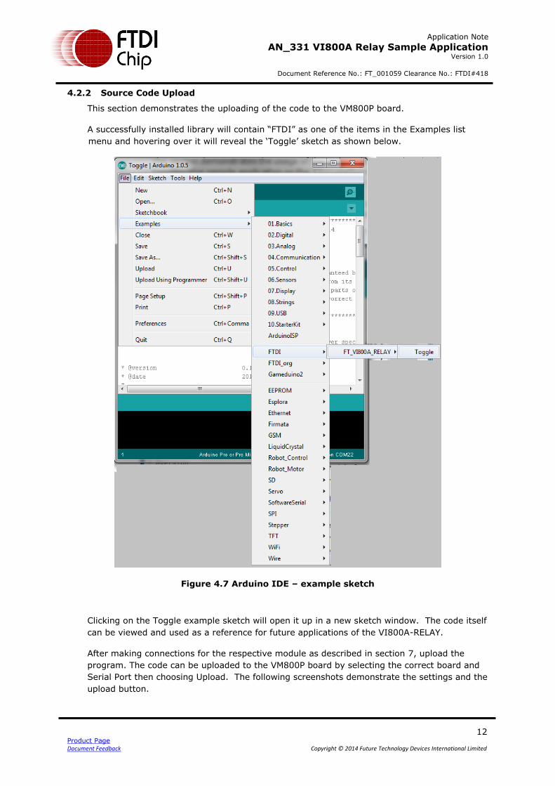
4.2.2 Source Code Upload
This section demonstrates the uploading of the code to the VM800P board.
A successfully installed library will contain “FTDI” as one of the items in the Examples list
menu and hovering over it will reveal the ‘Toggle’ sketch as shown below.
Figure 4.7 Arduino IDE – example sketch
Clicking on the Toggle example sketch will open it up in a new sketch window. The code itself
can be viewed and used as a reference for future applications of the VI800A-RELAY.
After making connections for the respective module as described in section 7, upload the
program. The code can be uploaded to the VM800P board by selecting the correct board and
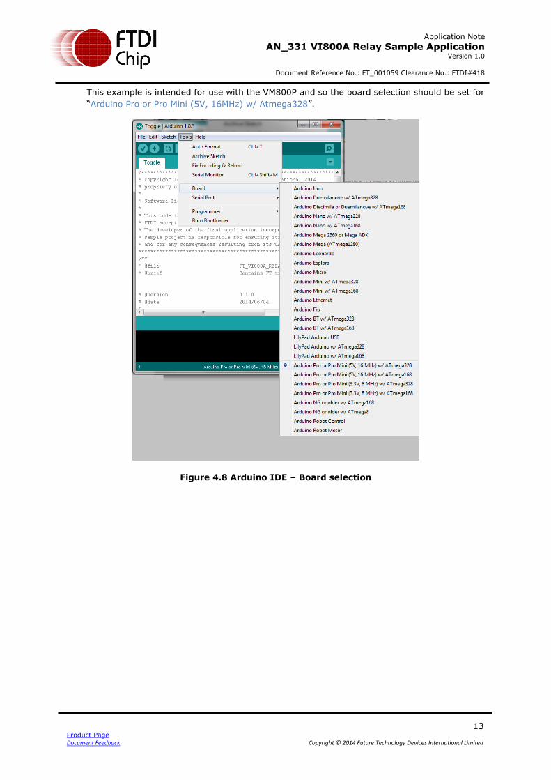
Serial Port then choosing Upload. The following screenshots demonstrate the settings and the
upload button.
Application Note
AN_331 VI800A Relay Sample Application Version 1.0
Document Reference No.: FT_001059 Clearance No.: FTDI#418
13 Product Page Document Feedback Copyright © 2014 Future Technology Devices International Limited
This example is intended for use with the VM800P and so the board selection should be set for
“Arduino Pro or Pro Mini (5V, 16MHz) w/ Atmega328”.
Figure 4.8 Arduino IDE – Board selection
Application Note
AN_331 VI800A Relay Sample Application Version 1.0
Document Reference No.: FT_001059 Clearance No.: FTDI#418
14 Product Page Document Feedback Copyright © 2014 Future Technology Devices International Limited
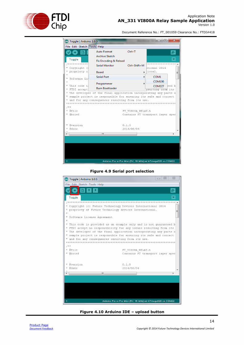
Figure 4.9 Serial port selection
Figure 4.10 Arduino IDE – upload button
Application Note
AN_331 VI800A Relay Sample Application Version 1.0
Document Reference No.: FT_001059 Clearance No.: FTDI#418
15 Product Page Document Feedback Copyright © 2014 Future Technology Devices International Limited
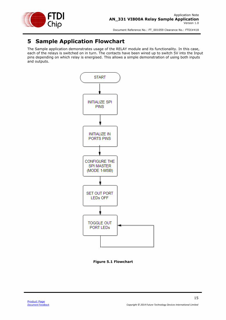
5 Sample Application Flowchart
The Sample application demonstrates usage of the RELAY module and its functionality. In this case, each of the relays is switched on in turn. The contacts have been wired up to switch 5V into the Input pins depending on which relay is energised. This allows a simple demonstration of using both inputs and outputs.
Figure 5.1 Flowchart
Application Note
AN_331 VI800A Relay Sample Application Version 1.0
Document Reference No.: FT_001059 Clearance No.: FTDI#418
16 Product Page Document Feedback Copyright © 2014 Future Technology Devices International Limited
6 Sample Application
This section explains the sample application based on the Arduino Library.
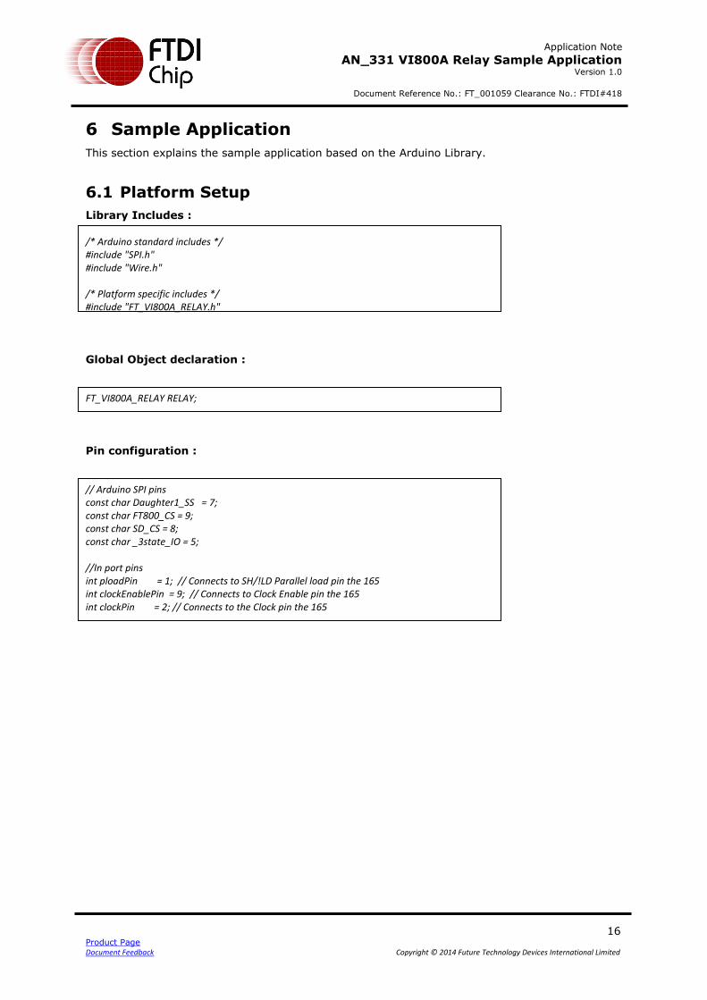
6.1 Platform Setup
Library Includes :
/* Arduino standard includes */ #include "SPI.h" #include "Wire.h" /* Platform specific includes */ #include "FT_VI800A_RELAY.h"
Global Object declaration : FT_VI800A_RELAY RELAY;
Pin configuration : // Arduino SPI pins const char Daughter1_SS = 7; const char FT800_CS = 9; const char SD_CS = 8; const char _3state_IO = 5; //In port pins int ploadPin = 1; // Connects to SH/!LD Parallel load pin the 165 int clockEnablePin = 9; // Connects to Clock Enable pin the 165 int clockPin = 2; // Connects to the Clock pin the 165
Application Note
AN_331 VI800A Relay Sample Application Version 1.0
Document Reference No.: FT_001059 Clearance No.: FTDI#418
17 Product Page Document Feedback Copyright © 2014 Future Technology Devices International Limited
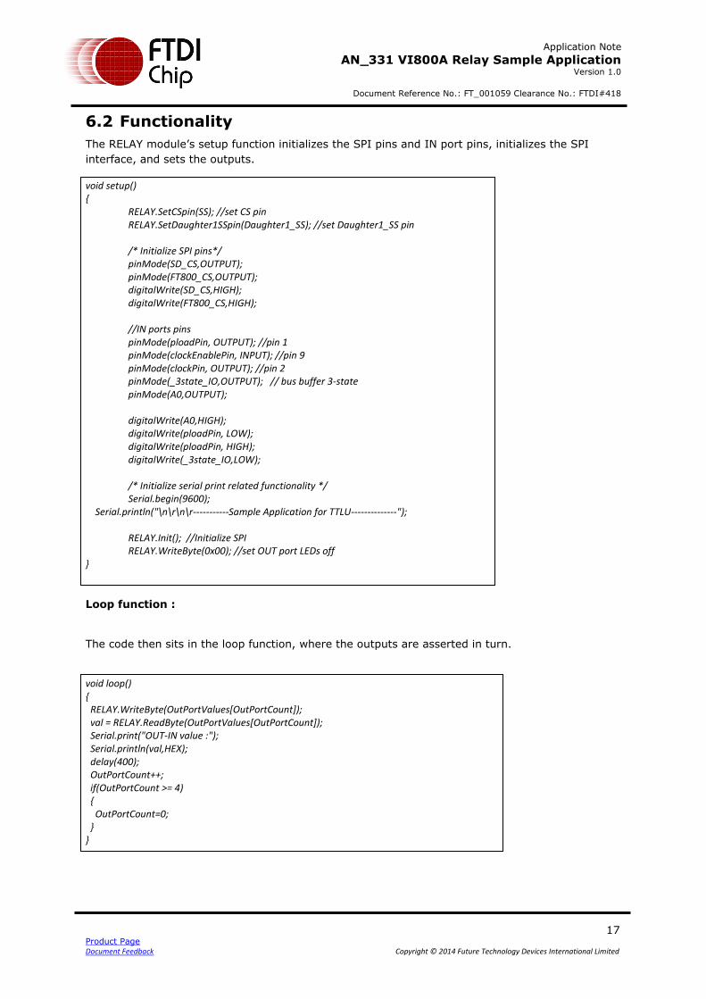
6.2 Functionality
The RELAY module’s setup function initializes the SPI pins and IN port pins, initializes the SPI
interface, and sets the outputs.
void setup() { RELAY.SetCSpin(SS); //set CS pin RELAY.SetDaughter1SSpin(Daughter1_SS); //set Daughter1_SS pin /* Initialize SPI pins*/ pinMode(SD_CS,OUTPUT); pinMode(FT800_CS,OUTPUT); digitalWrite(SD_CS,HIGH); digitalWrite(FT800_CS,HIGH); //IN ports pins pinMode(ploadPin, OUTPUT); //pin 1 pinMode(clockEnablePin, INPUT); //pin 9 pinMode(clockPin, OUTPUT); //pin 2 pinMode(_3state_IO,OUTPUT); // bus buffer 3-state pinMode(A0,OUTPUT); digitalWrite(A0,HIGH); digitalWrite(ploadPin, LOW); digitalWrite(ploadPin, HIGH); digitalWrite(_3state_IO,LOW); /* Initialize serial print related functionality */ Serial.begin(9600); Serial.println("\n\r\n\r-----------Sample Application for TTLU--------------"); RELAY.Init(); //Initialize SPI RELAY.WriteByte(0x00); //set OUT port LEDs off }
Loop function :
The code then sits in the loop function, where the outputs are asserted in turn.
void loop() { RELAY.WriteByte(OutPortValues[OutPortCount]); val = RELAY.ReadByte(OutPortValues[OutPortCount]); Serial.print("OUT-IN value :"); Serial.println(val,HEX); delay(400); OutPortCount++; if(OutPortCount >= 4) { OutPortCount=0; } }
Application Note
AN_331 VI800A Relay Sample Application Version 1.0
Document Reference No.: FT_001059 Clearance No.: FTDI#418
18 Product Page Document Feedback Copyright © 2014 Future Technology Devices International Limited
7 Application execution
The use of the sample application is described below.
1. Ensure that the VI800A-RELAY is connected to the VM800P’s J5 expansion connector. The VM800P must be powered down when connecting or disconnecting any expansion cards to avoid damage.
2. The loopback connections between the relay contacts and the Input pins can then be
made. In this example, FTDI USB-UART cables (red wire = 5V, black wire = 0V) were used for the 5V and 0V external supplies used to provide power to the contacts of the relays. Other 5V supplies could be used instead.
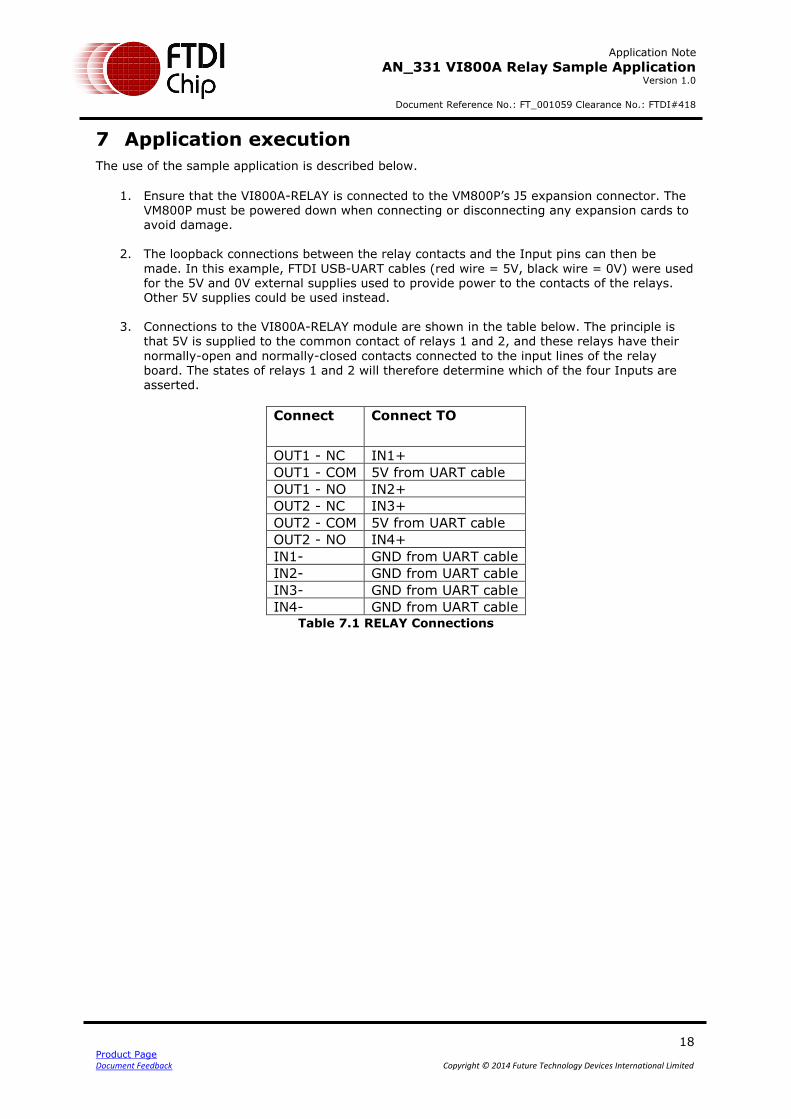
3. Connections to the VI800A-RELAY module are shown in the table below. The principle is that 5V is supplied to the common contact of relays 1 and 2, and these relays have their
normally-open and normally-closed contacts connected to the input lines of the relay
board. The states of relays 1 and 2 will therefore determine which of the four Inputs are asserted.
Connect Connect TO
OUT1 - NC IN1+
OUT1 - COM 5V from UART cable
OUT1 - NO IN2+
OUT2 - NC IN3+
OUT2 - COM 5V from UART cable
OUT2 - NO IN4+
IN1- GND from UART cable
IN2- GND from UART cable
IN3- GND from UART cable
IN4- GND from UART cable Table 7.1 RELAY Connections
Application Note
AN_331 VI800A Relay Sample Application Version 1.0
Document Reference No.: FT_001059 Clearance No.: FTDI#418
19 Product Page Document Feedback Copyright © 2014 Future Technology Devices International Limited
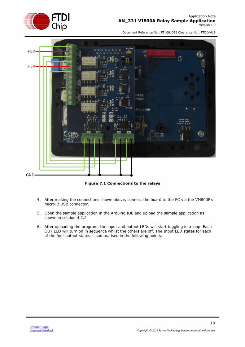
Figure 7.1 Connections to the relays
4. After making the connections shown above, connect the board to the PC via the VM800P’s micro-B USB connector.
5. Open the sample application in the Arduino IDE and upload the sample application as shown in section 4.2.2
6. After uploading the program, the input and output LEDs will start toggling in a loop. Each
OUT LED will turn on in sequence whilst the others are off. The Input LED states for each of the four output states is summarised in the following points:
+5V
+5V
GND
Application Note
AN_331 VI800A Relay Sample Application Version 1.0
Document Reference No.: FT_001059 Clearance No.: FTDI#418
20 Product Page Document Feedback Copyright © 2014 Future Technology Devices International Limited
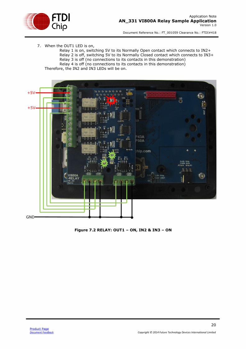
7. When the OUT1 LED is on,
Relay 1 is on, switching 5V to its Normally Open contact which connects to IN2+ Relay 2 is off, switching 5V to its Normally Closed contact which connects to IN3+ Relay 3 is off (no connections to its contacts in this demonstration) Relay 4 is off (no connections to its contacts in this demonstration)
Therefore, the IN2 and IN3 LEDs will be on.
Figure 7.2 RELAY: OUT1 – ON, IN2 & IN3 – ON
+5V
+5V
GND
Application Note
AN_331 VI800A Relay Sample Application Version 1.0
Document Reference No.: FT_001059 Clearance No.: FTDI#418
21 Product Page Document Feedback Copyright © 2014 Future Technology Devices International Limited
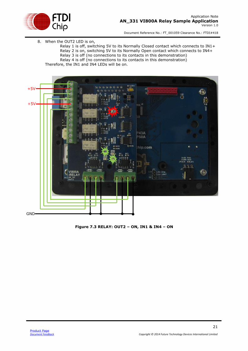
8. When the OUT2 LED is on, Relay 1 is off, switching 5V to its Normally Closed contact which connects to IN1+
Relay 2 is on, switching 5V to its Normally Open contact which connects to IN4+ Relay 3 is off (no connections to its contacts in this demonstration) Relay 4 is off (no connections to its contacts in this demonstration)
Therefore, the IN1 and IN4 LEDs will be on.
Figure 7.3 RELAY: OUT2 – ON, IN1 & IN4 – ON
+5V
+5V
GND

Application Note
AN_331 VI800A Relay Sample Application Version 1.0
Document Reference No.: FT_001059 Clearance No.: FTDI#418
22 Product Page Document Feedback Copyright © 2014 Future Technology Devices International Limited
9. When the OUT3 LED is on, Relay 1 is off, switching 5V to its Normally Closed contact which connects to IN1+
Relay 2 is off, switching 5V to its Normally Closed contact which connects to IN3+ Relay 3 is on (no connections to its contacts in this demonstration) Relay 4 is off (no connections to its contacts in this demonstration)
Therefore, the IN1 and IN3 LEDs will be on.
Figure 7.4 RELAY: OUT3 – ON, IN1 & IN3 – ON
+5V
+5V
GND
Application Note
AN_331 VI800A Relay Sample Application Version 1.0
Document Reference No.: FT_001059 Clearance No.: FTDI#418
23 Product Page Document Feedback Copyright © 2014 Future Technology Devices International Limited
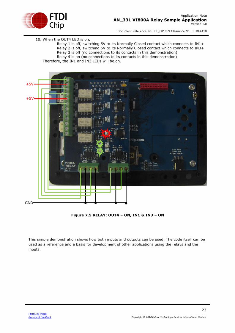
10. When the OUT4 LED is on, Relay 1 is off, switching 5V to its Normally Closed contact which connects to IN1+
Relay 2 is off, switching 5V to its Normally Closed contact which connects to IN3+ Relay 3 is off (no connections to its contacts in this demonstration) Relay 4 is on (no connections to its contacts in this demonstration)
Therefore, the IN1 and IN3 LEDs will be on.
Figure 7.5 RELAY: OUT4 – ON, IN1 & IN3 – ON
This simple demonstration shows how both inputs and outputs can be used. The code itself can be
used as a reference and a basis for development of other applications using the relays and the
inputs.
+5V
+5V
GND

Application Note
AN_331 VI800A Relay Sample Application Version 1.0
Document Reference No.: FT_001059 Clearance No.: FTDI#418
24 Product Page Document Feedback Copyright © 2014 Future Technology Devices International Limited
8 Contact Information
Head Office – Glasgow, UK
Future Technology Devices International Limited Unit 1, 2 Seaward Place, Centurion Business Park Glasgow G41 1HH United Kingdom Tel: +44 (0) 141 429 2777
Fax: +44 (0) 141 429 2758 E-mail (Sales) [email protected]
E-mail (Support) [email protected]
E-mail (General Enquiries) [email protected]
Branch Office – Taipei, Taiwan
Future Technology Devices International Limited (Taiwan) 2F, No. 516, Sec. 1, NeiHu Road Taipei 114 Taiwan , R.O.C. Tel: +886 (0) 2 8791 3570 Fax: +886 (0) 2 8791 3576 E-mail (Sales) [email protected]
E-mail (Support) [email protected]
E-mail (General Enquiries) [email protected]
Branch Office – Tigard, Oregon, USA
Future Technology Devices International Limited (USA) 7130 SW Fir Loop Tigard, OR 97223-8160 USA
Tel: +1 (503) 547 0988 Fax: +1 (503) 547 0987 E-Mail (Sales) [email protected]
E-Mail (Support) [email protected]
E-Mail (General Enquiries) [email protected]
Branch Office – Shanghai, China
Future Technology Devices International Limited (China) Room 1103, No. 666 West Huaihai Road, Shanghai, 200052 China Tel: +86 21 62351596 Fax: +86 21 62351595 E-mail (Sales) [email protected]
E-mail (Support) [email protected]
E-mail (General Enquiries) [email protected]
Web Site
http://ftdichip.com
Distributor and Sales Representatives
Please visit the Sales Network page of the FTDI Web site for the contact details of our distributor(s) and sales
representative(s) in your country.
System and equipment manufacturers and designers are responsible to ensure that their systems, and any Future Technology
Devices International Ltd (FTDI) devices incorporated in their systems, meet all applicable safety, regulatory and system-level
performance requirements. All application-related information in this document (including application descriptions, suggested
FTDI devices and other materials) is provided for reference only. While FTDI has taken care to assure it is accurate, this
information is subject to customer confirmation, and FTDI disclaims all liability for system designs and for any applications
assistance provided by FTDI. Use of FTDI devices in life support and/or safety applications is entirely at the user’s risk, and the
user agrees to defend, indemnify and hold harmless FTDI from any and all damages, claims, suits or expense resulting from
such use. This document is subject to change without notice. No freedom to use patents or other intellectual property rights is
implied by the publication of this document. Neither the whole nor any part of the information contained in, or the product
described in this document, may be adapted or reproduced in any material or electronic form without the prior written consent
of the copyright holder. Future Technology Devices International Ltd, Unit 1, 2 Seaward Place, Centurion Business Park,
Glasgow G41 1HH, United Kingdom. Scotland Registered Company Number: SC136640
Application Note
AN_331 VI800A_Relay_SampleApp Version 1.0
Document Reference No.: FT_001069 Clearance No.: FTDI#418
25 Product Page
Document Feedback Copyright © 2014 Future Technology Devices International Limited
Appendix A– References
Document References
1. FT800 Datasheet 2. VI800A-RELAY Datasheet 3. EVE Product Page 4. Arduino IDE 5. Example code for VI800A-RELAY
Acronyms and Abbreviations
Terms Description
Arduino Pro The open source platform variety based on ATMEL’s ATMEGA chipset
EVE Embedded Video Engine
SPI Serial Peripheral Interface
UI User Interface
USB Universal Serial Bus
Application Note
AN_331 VI800A_Relay_SampleApp Version 1.0
Document Reference No.: FT_001069 Clearance No.: FTDI#418
26 Product Page
Document Feedback Copyright © 2014 Future Technology Devices International Limited
Appendix B – List of Tables & Figures
List of Tables
Table 3.1 API description ........................................................................................... 7
Table 7.1 RELAY Connections ................................................................................... 18
List of Figures
Figure 2.1 Block Diagram of Setup ............................................................................. 4
Figure 2.2 Arduino Library SampleApp Architecture diagram ..................................... 4
Figure 3.1 FTDI Library folder contents ...................................................................... 6
Figure 3.2 FTDI Library - examples folder .................................................................. 6
Figure 3.3 FTDI Library - libraries folder .................................................................... 6
Figure 3.4 FTDI Library - platform headers ................................................................ 6
Figure 4.1 VM800P Board ........................................................................................... 8
Figure 4.2 VI800A-RELAY module .............................................................................. 8
Figure 4.3 VI800A-RELAY module connected to VM800P ........................................... 9
Figure 4.4 Arduino IDE – add library option ............................................................. 10
Figure 4.5 Arduino IDE - library selection browser ................................................... 11
Figure 4.6 Library Installation - Manual Installation ................................................ 11
Figure 4.7 Arduino IDE – example sketch ................................................................ 12
Figure 4.8 Arduino IDE – Board selection ................................................................. 13
Figure 4.9 Serial port selection ................................................................................ 14
Figure 4.10 Arduino IDE – upload button ................................................................. 14
Figure 5.1 Flowchart ................................................................................................ 15
Figure 7.1 Connections to the relays ........................................................................ 19
Figure 7.2 RELAY: OUT1 – ON, IN2 & IN3 – ON ........................................................ 20
Figure 7.3 RELAY: OUT2 – ON, IN1 & IN4 – ON ........................................................ 21
Figure 7.4 RELAY: OUT3 – ON, IN1 & IN3 – ON ........................................................ 22
Figure 7.5 RELAY: OUT4 – ON, IN1 & IN3 – ON ........................................................ 23
Application Note
AN_331 VI800A_Relay_SampleApp Version 1.0
Document Reference No.: FT_001069 Clearance No.: FTDI#418
27 Product Page
Document Feedback Copyright © 2014 Future Technology Devices International Limited
9 Appendix C– Revision History
Document Title: AN_331 VI800A Relay Sample Application
Document Reference No.: FT_001069
Clearance No.: FTDI#418
Product Page: http://www.ftdichip.com/EVE.htm
Document Feedback: Send Feedback
Revision Changes Date
1.0 Initial release 2014-10-23