· web viewthe axometrics tunable visible source includes a low-noise, 150 w xenon arc lamp and...
TRANSCRIPT
Axometrics, Inc.103 Quality Circle, Suite 215Huntsville, AL 35806Phone: (256) 704-3332Fax: (256) 971-2073
E-Mail: [email protected]: http://www.axometrics.com
MMSP-VISSpectro-Polarimeter Optionwith Tunable Visible Source
HARDWARE MANUAL
Rev 2/2011
©2011 Axometrics, Inc. All rights reserved.AxoScan, AxoView, Axometrics and the Axometrics logo are trademarks of Axometrics, Inc.

ii

Please read these instructions completely and carefully before operating the Mueller Matrix Polarimeter. If you have any questions, or experience any difficulties, please contact Axometrics or the representative from whom the instrument was purchased.
iii

iv

CONTENTS
1 Introduction......................................................................................................................................... 32 Unpacking and Setup......................................................................................................................... 4
2.1 General Safety........................................................................................................................... 42.1.1 Electrical................................................................................................................................ 42.1.2 Mechanical............................................................................................................................ 42.1.3 Optical................................................................................................................................... 42.1.4 Do Not Start When Hot..........................................................................................................4
2.2 Shipment Contents.................................................................................................................... 42.3 Setting Up the Tunable Spectral Source....................................................................................5
3 Operation and Maintanence.............................................................................................................103.1 Bulb Life................................................................................................................................... 103.2 Calibration................................................................................................................................ 10
1
2

1 INTRODUCTION
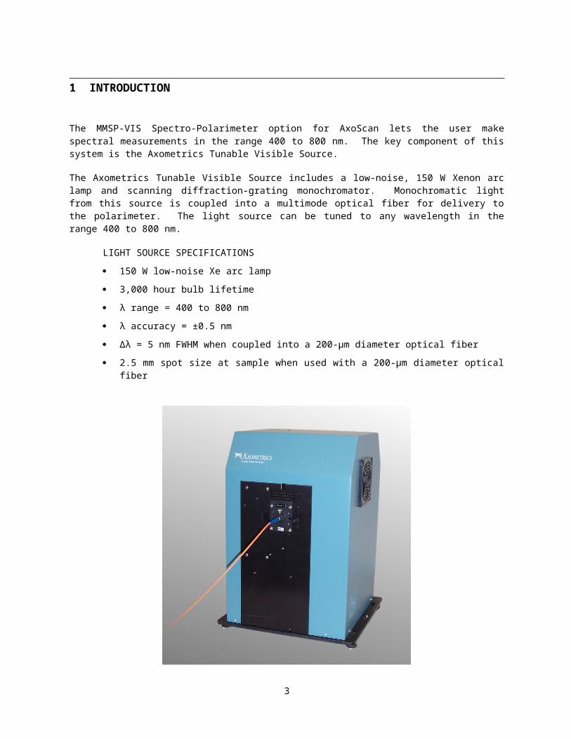
The MMSP-VIS Spectro-Polarimeter option for AxoScan lets the user make spectral measurements in the range 400 to 800 nm. The key component of this system is the Axometrics Tunable Visible Source.
The Axometrics Tunable Visible Source includes a low-noise, 150 W Xenon arc lamp and scanning diffraction-grating monochromator. Monochromatic light from this source is coupled into a multimode optical fiber for delivery to the polarimeter. The light source can be tuned to any wavelength in the range 400 to 800 nm.
LIGHT SOURCE SPECIFICATIONS
150 W low-noise Xe arc lamp
3,000 hour bulb lifetime
λ range = 400 to 800 nm
λ accuracy = ±0.5 nm
Δλ = 5 nm FWHM when coupled into a 200-μm diameter optical fiber
2.5 mm spot size at sample when used with a 200-μm diameter optical fiber
The light source is controlled by the AxoScan Control Unit computer via RS-232. Control of the light source control has been tightly integrated into the AxoView™ polarimeter software to allow automated spectral measurements. AxoView also includes powerful data visualization functions for analysis of measured polarization spectra. See the AxoView Users Manual for details.
3
2 UNPACKING AND SETUP
2.1 General Safety
2.1.1 ELECTRICAL
The Tunable Visible Source has a high voltage ignitor and power supply built into the lamp and grating housing. A number of safety features, including a door interlock, ensure the user’s safety.
The input power supply was setup at the factor to either accept 110 VAC or to accept 220 VAC. Check the sticker on the back of your system and make certain you are using the correct input power. Using the incorrect input power will damage the system.
Do not open the Tunable Visible Source electrical compartment without first disconnecting the power cord, since you may contact live voltage areas inside the compartment even with the power switch in the “off” position. Note: This instrument conforms to European CE standards for both safety and EMC.
2.1.2 MECHANICAL
Avoid dropping, sudden shocks, or rough handling of the Tunable Visible Source since this may cause the instrument to lose its calibration and may destroy the high precision drive components and/or optics.
Position the instrument in its intended location before mounting the lamp, and avoid frequent moving once the lamp is installed.
2.1.3 OPTICAL
Do not touch any optical surfaces since this is likely to cause irreparable damage. Do not attempt to clean any optical surface except by blowing off dust or lint particles with a stream of dry clean air or nitrogen.
Handle the lamp bulb only by its base and always with gloves to avoid transferring finger oils to the glass of the bulb. Oil from your fingers on the bulb glass can super-heat during operation and cause the bulb to explode.
2.1.4 DO NOT START WHEN HOT
NOTE: When you turn off the lamp, allow it to cool for 30 minutes before turning the unit back on. Restarting a hot bulb will decrease its lifetime.
2.1.5 OPTICAL RADIATION HAZARD
Never look directly into the light source. Light levels can permanently damage your eyes. Avoid prolonged exposure of light directly onto your skin due to potential UV hazard. Never operate the light source with the cover off due to extremely dangerous light and UV levels that can damage your eyes and skin.
2.2 Shipment ContentsThe MMSP-VIS Spectro-polarimeter option includes the following components:
1. This Operator’s Manual
2. AxoScan Tunable Visible Source
4

3. 150 W Xe arc lamp with alignment base
4. RS-232 serial cable
5. 200-μm diameter, 5 m optical fiber
6. Two (2) SMA ferules
7. Collimator tube assembly
8. Power cord
2.3 Setting Up the Tunable Spectral SourceThe following steps are required for installation:
1. Remove the Tunable Spectral Source from its box
2. Remove all of the screws that hold on the blue cover of the Tunable Spectral Source
a. This step will require a screwdriver
3. Lift the blue cover off of the source
4. Remove the arc lamp bulb from its package, and remove its protective plastic case.
a. It is imperative that you never touch the glass of the arc lamp bulb with your fingers. Oils from your skin can cause the bulb to explode when heated during operation.
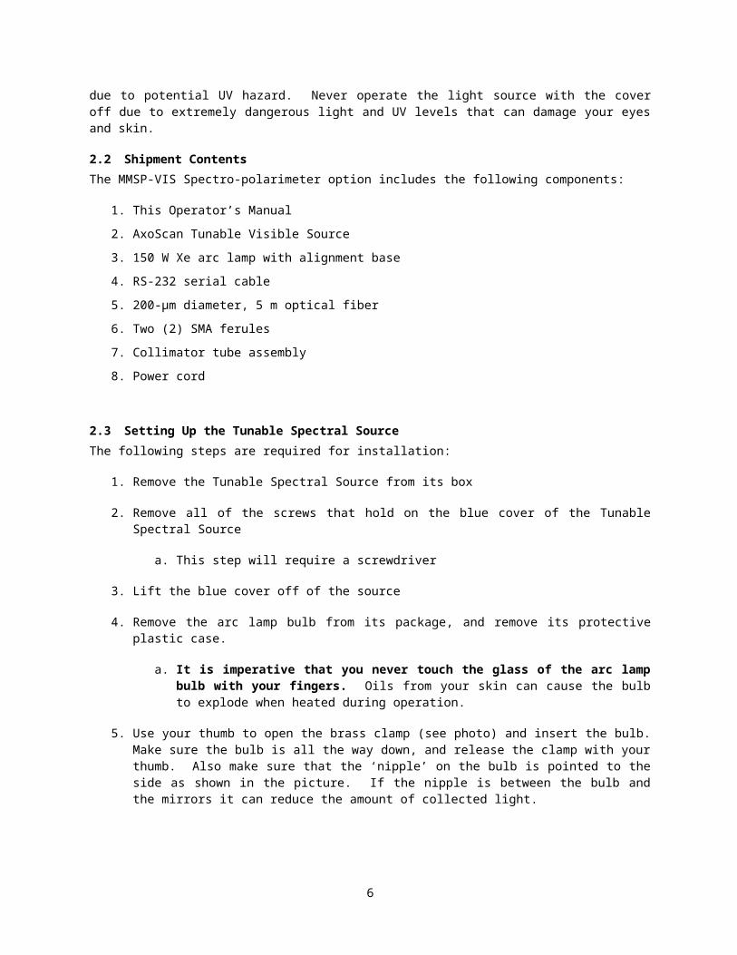
5. Use your thumb to open the brass clamp (see photo) and insert the bulb. Make sure the bulb is all the way down, and release the clamp with your thumb. Also make sure that the ‘nipple’ on the bulb is pointed to the side as shown in the picture. If the nipple is between the bulb and the mirrors it can reduce the amount of collected light.
5
6. Attach the white power cable and secure the thumb-screw
7. Put the blue cover back on the source and secure the screws that hold it in place.
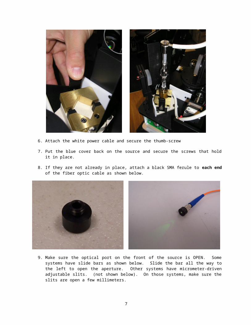
8. If they are not already in place, attach a black SMA ferule to each end of the fiber optic cable as shown below.
9. Make sure the optical port on the front of the source is OPEN. Some systems have slide bars as shown below. Slide the bar all the way to the left to open the aperture. Other systems have micrometer-driven adjustable slits. (not shown below). On those systems, make sure the slits are open a few millimeters.
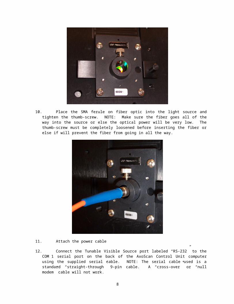
10. Place the SMA ferule on fiber optic into the light source and tighten the thumb-screw. NOTE: Make sure the fiber goes all of the way into the source or else the optical power will be very low. The thumb-screw must be completely loosened before inserting the fiber or else if will prevent the fiber from going in all the way.
6
11. Attach the power cable
12. Connect the Tunable Visible Source port labeled “RS-232” to the COM 1 serial port on the back of the AxoScan Control Unit computer using the supplied serial cable. NOTE: The serial cable used is a standard “straight-through” 9-pin cable. A “cross-over” or “null modem” cable will not work.
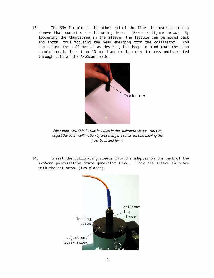
13. The SMA ferrule on the other end of the fiber is inserted into a sleeve that contains a collimating lens. (See the figure below) By loosening the thumbscrew in the sleeve, the ferrule can be moved back and forth, thus focusing the beam emerging from the collimator. You can adjust the collimation as desired, but keep in mind that the beam should remain less than 10 mm diameter in order to pass unobstructed through both of the AxoScan heads.
Fiber optic with SMA ferrule installed in the collimator sleeve. You canadjust the beam collimation by loosening the set-screw and moving the
fiber back and forth.
Thumbscrew
7
14. Insert the collimating sleeve into the adapter on the back of the AxoScan polarization state generator (PSG). Lock the sleeve in place with the set-screw (two places).
15. Now, the beam of light should be clearly visible coming out the front of the PSG head. The beam needs to be well-centered on the output window of the PSG. If the beam is not well centered, you will need to adjust the tip and tilt of the adapter plate on the PSG input. Do this by loosening all three locking screws and then turning the adjustment screws until the beam is centered in the output window of the PSG. Tighten the locking screws. You might need to repeat this process a few times.
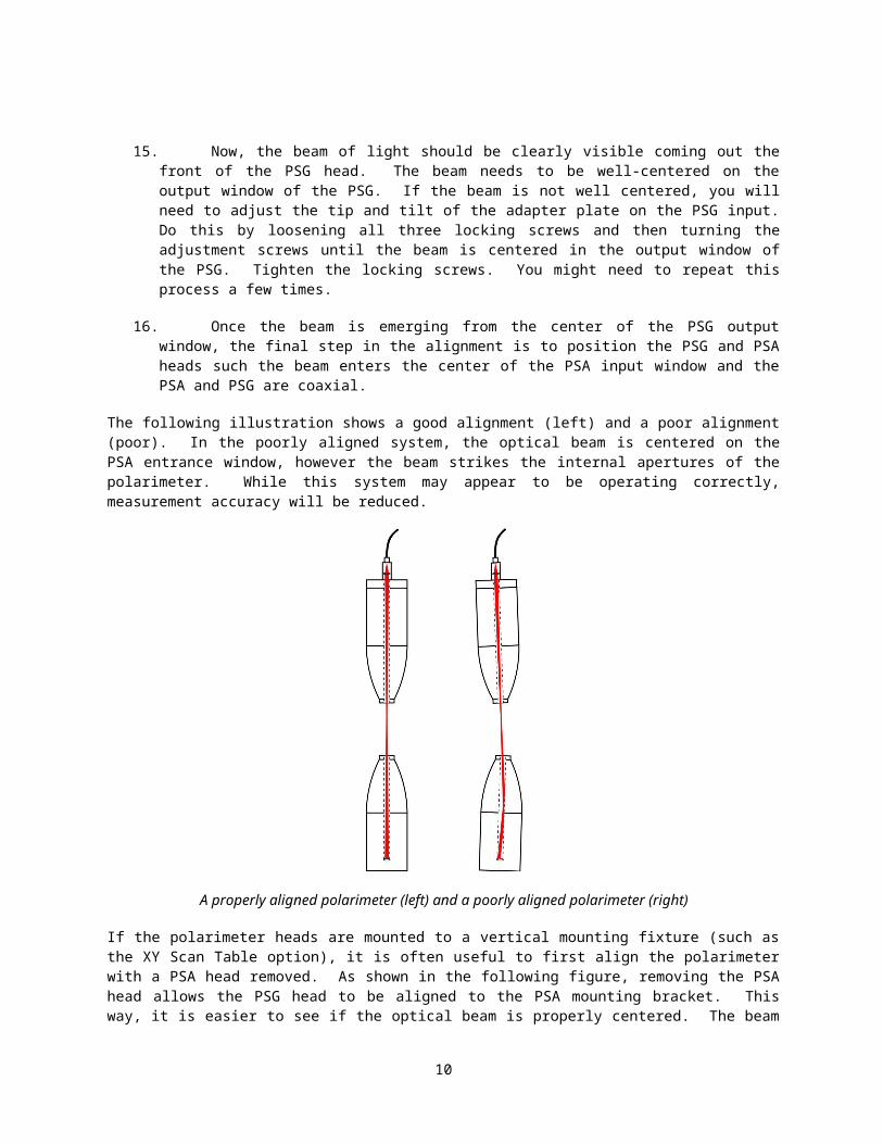
16. Once the beam is emerging from the center of the PSG output window, the final step in the alignment is to position the PSG and PSA heads such the beam enters the center of the PSA input window and the PSA and PSG are coaxial.
The following illustration shows a good alignment (left) and a poor alignment (poor). In the poorly aligned system, the optical beam is centered on the PSA entrance window, however the beam strikes the internal apertures of the polarimeter. While this system may appear to be operating correctly, measurement accuracy will be reduced.
adapter plate set-screws
locking screw
adjustment screw screw
collimating sleeve
8
A properly aligned polarimeter (left) and a poorly aligned polarimeter (right)
If the polarimeter heads are mounted to a vertical mounting fixture (such as the XY Scan Table option), it is often useful to first align the polarimeter with a PSA head removed. As shown in the following figure, removing the PSA head allows the PSG head to be aligned to the PSA mounting bracket. This way, it is easier to see if the optical beam is properly centered. The beam should be centered approximately 34 mm above the mounting bracket, and should be aligned along the mounting bolts on the bracket. Also, the fiber-optic collimator should be focused so that the beam diameter is not much more that 10 mm diameter at the PSA location. Once this step is finished, attach the PSA head and adjust it to center the beam on the input window.
Aligning the PSG head to the PSA mounting bracket. The optical beam should becentered 34 mm from the bracket and lined up along the mounting bolts.
9
3 OPERATION AND MAINTANENCE
Control of the tunable course is completely integrated into the AxoView software. Refer to the AxoView Users Manual for all information regarding the operation of the light source.
3.1 Bulb LifeThe Xe arc lamp bulbs used in the Tunable Visible Source have a rated lifetime of 3,000 hours.Axometrics recommends changing the bulb after 2,000 hours for optimum performance. Toward the endof its life, the bulbs have very low optical power near 400 nm, and AxoScan measurement noise willbegin to increase at wavelengths near 400 nm.
3.2 CalibrationYour light source was calibrated at the factory at a wavelength of 537.4 nm using an absorption line of a NIST traceable Holmium Oxide calibration filter. Your source should be calibrated to within 0.3 nm at this wavelength. Across the entire 400 to 800 nm working range of the source, your calibration should be correct to within +/- 2 nm.
A Holmium Oxide Filter was shipped with your system, and can be used to recalibrate your source if needed. The following procedure outlines the required steps.
Make sure the AxoScan Engine is running. Find the program Visible Tunable Source Calibration.exe in your AxoView software folder. You should see the following screen:
Place the Holmium Oxide calibration onto the AxoScan measurement stage. Make sure that the AxoScan beam is passing through the filter.
Press the COURSE MEASUREMENT to complete Step 1. This step will measure the filter from 500 to 700 nm in 1 nm steps. This step requires approximately 1 minute to complete. When finished, you willsee the measured data:
10
In Step 1, the measured transmission spectrum (red) is compared the known spectrum of Holmium Oxide glass (black). This data is used to estimate the wavelength error in the source. The absorption band indicated at the arrow should be at 537.4 nm.
NOTE: If the graph looks significantly different than this, do NOT proceed. Only proceed to Step 2 if you can clearly see that the black and the red spectra look similar, like shown above. If they black and red lines are completely different, contact Axometrics or your local representative for support.
Press FINE MEASUREMENT to complete Step 2. This step measures the filter in 0.5 nm steps, centered on the approximate value measured in Step 1. The center value based on a curve-fit is reported as the MEASURED MINIMUM. For a perfectly calibrated Source, the minimum value should be 537.4 nm.
If everything has worked properly, you should see a parabolic curve-fit (black) shown over the measurement data (red) as shown above. If everything has worked properly, you can press UPDATE SOURCE CALIBRATION in Step 3 to save the new calibration information permanently into the memory of the Tunable Visible Source.
IMPORTANT NOTE – Only press UPDATE SOURCE CALIBRATION if the measurements look similar to those shown above. Do not press the button if you are not sure that the software has correctly identified the 537.4 nm absorption band. If you need assistance, contact Axometrics or your local representative for support.
After these steps are completed, the calibration is finished and you should recalibrate your AxoScan.
Contact Axometrics or your local agent if you believe that your source calibration has changed. Sources can be re-calibrated in the field by Axometrics personnel.
11