viking surefire pre-action systems - tftf.org.t°¡報.pdf · surefire pre-action systems are:...
TRANSCRIPT
VikingSureFire
Pre-actionSystems
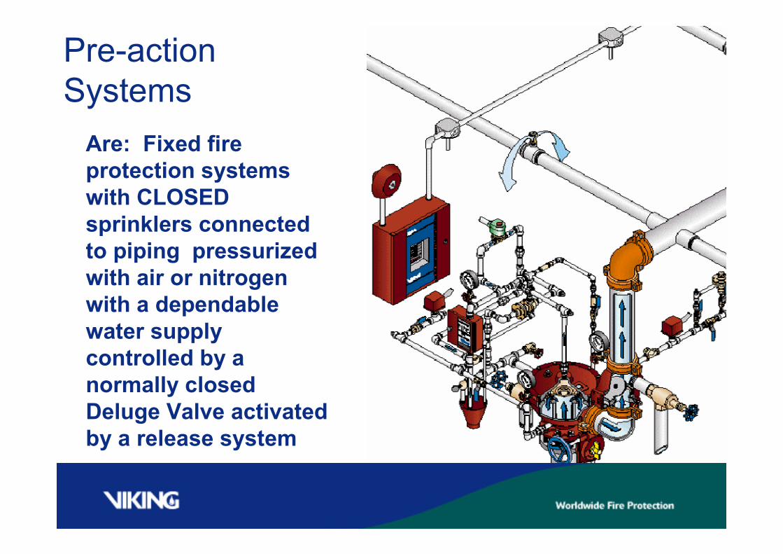
Pre-actionSystems
Are: Fixed fireprotection systemswith CLOSEDsprinklers connectedto piping pressurizedwith air or nitrogenwith a dependablewater supplycontrolled by anormally closedDeluge Valve activatedby a release system
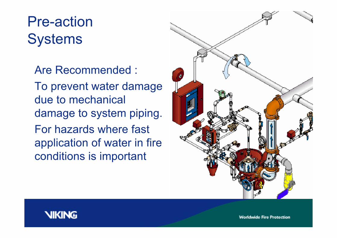
Pre-actionSystems
Are Recommended :To prevent water damagedue to mechanicaldamage to system piping.For hazards where fastapplication of water in fireconditions is important
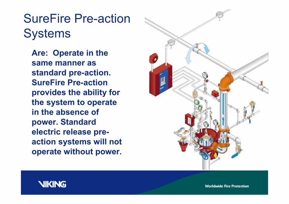
SureFire Pre-actionSystems
Are: Operate in thesame manner asstandard pre-action.SureFire Pre-actionprovides the ability forthe system to operatein the absence ofpower. Standardelectric release pre-action systems will notoperate without power.
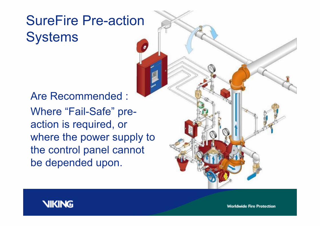
SureFire Pre-actionSystems
Are Recommended :Where “Fail-Safe” pre-action is required, orwhere the power supply tothe control panel cannotbe depended upon.
The Release System must activate …..-(Detection ) Solenoid valve opens-(an alarm will sound)
In fire conditions,-After the release system operates water travels from theDeluge Valve to the open sprinkler.-Upon sprinkler opening water flows from sprinkler orificeonto fire.Single interlock preaction does not have the water deliverydelay that a double interlock preaction system has.
SINGLE INTERLOCKED OPERATION
SYSTEMCOMPONENTS
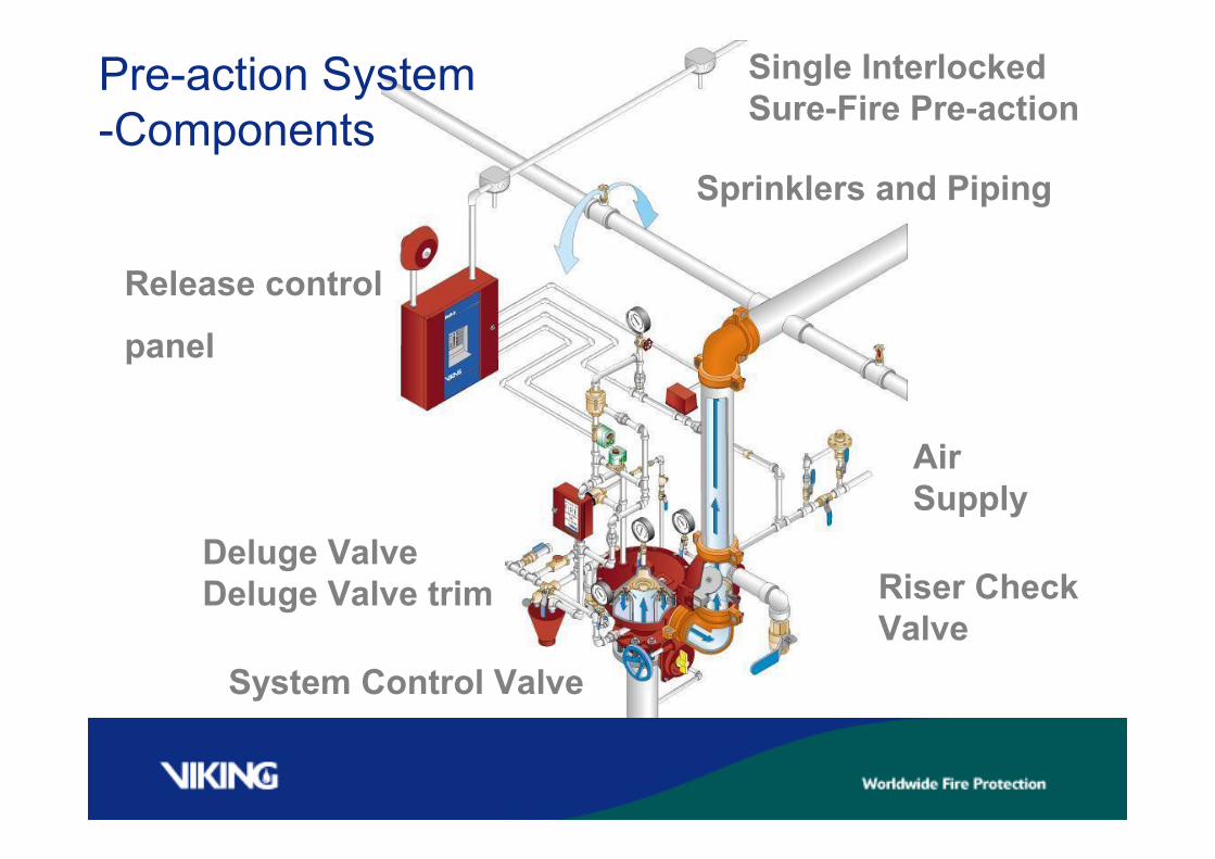
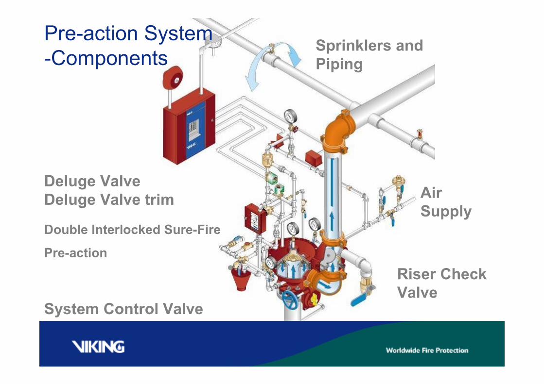
Pre-action System-Components
Deluge ValveDeluge Valve trim
System Control Valve
Sprinklers and Piping
AirSupply
Riser CheckValve
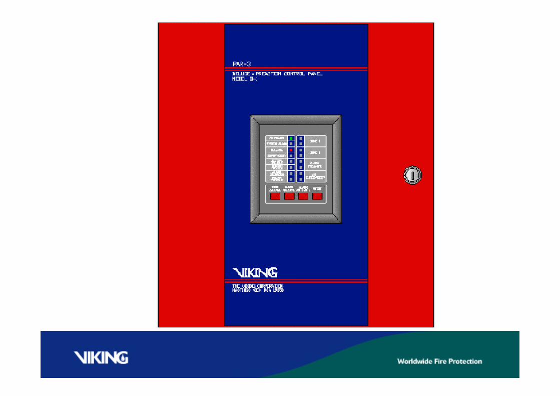
Release control
panel
Single InterlockedSure-Fire Pre-action
Pre-action System-Components
Deluge ValveDeluge Valve trim
System Control Valve
Sprinklers andPiping
AirSupply
Riser CheckValve
Double Interlocked Sure-Fire
Pre-action

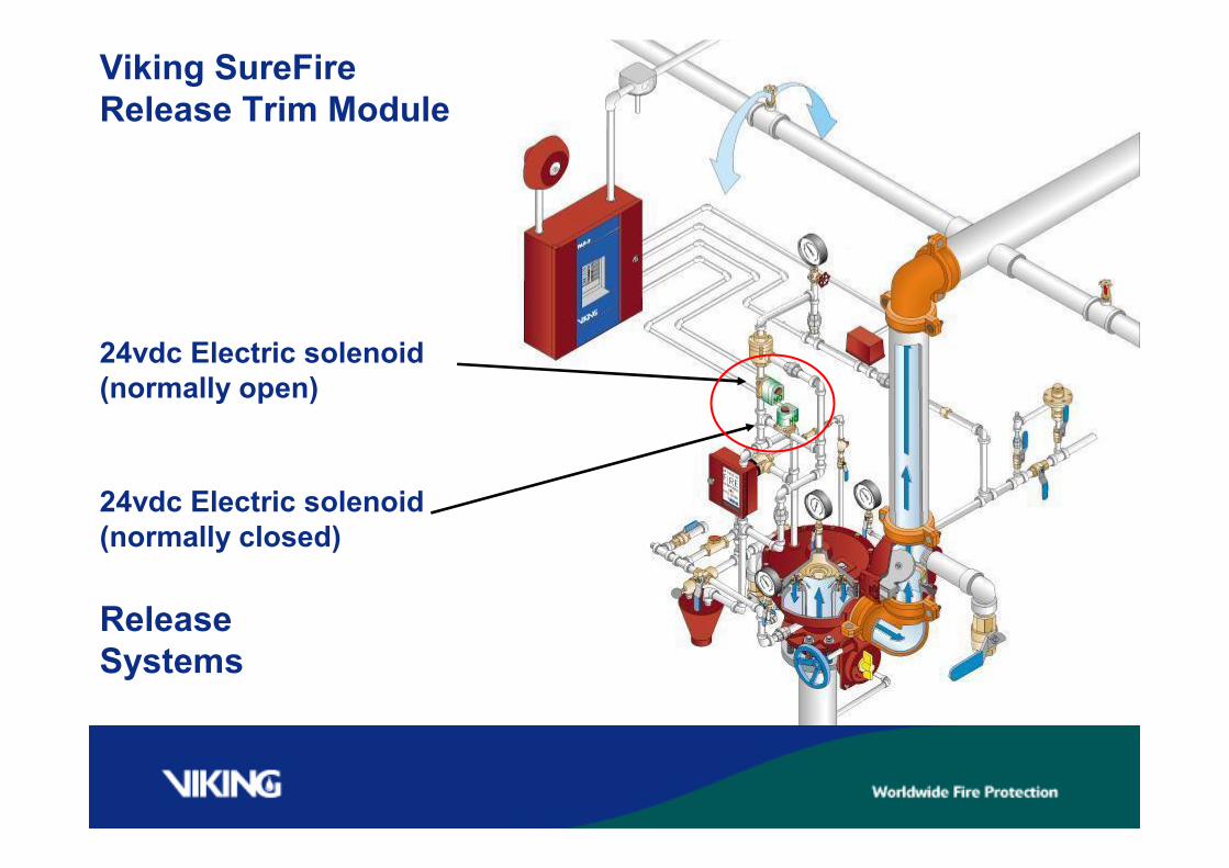
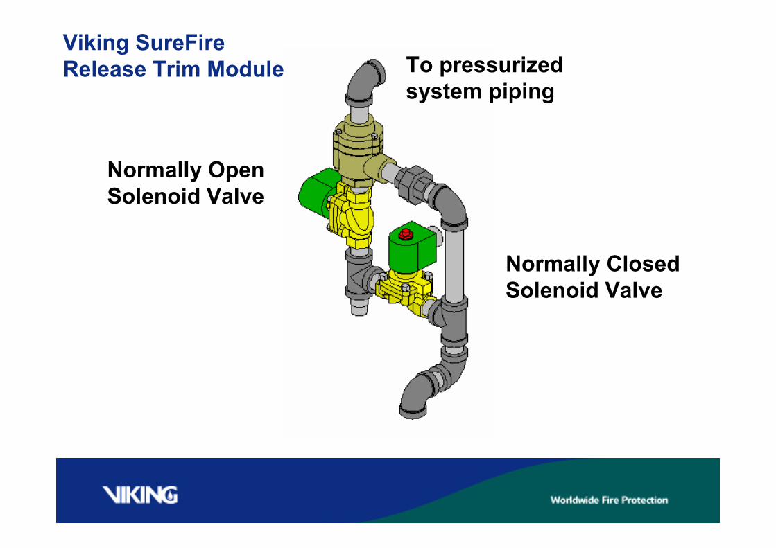
Viking SureFireRelease Trim Module
Normally OpenSolenoid Valve
Normally ClosedSolenoid Valve
To pressurizedsystem piping
VIKING DELUGEVALVES
Deluge Valves
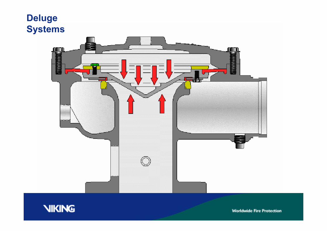
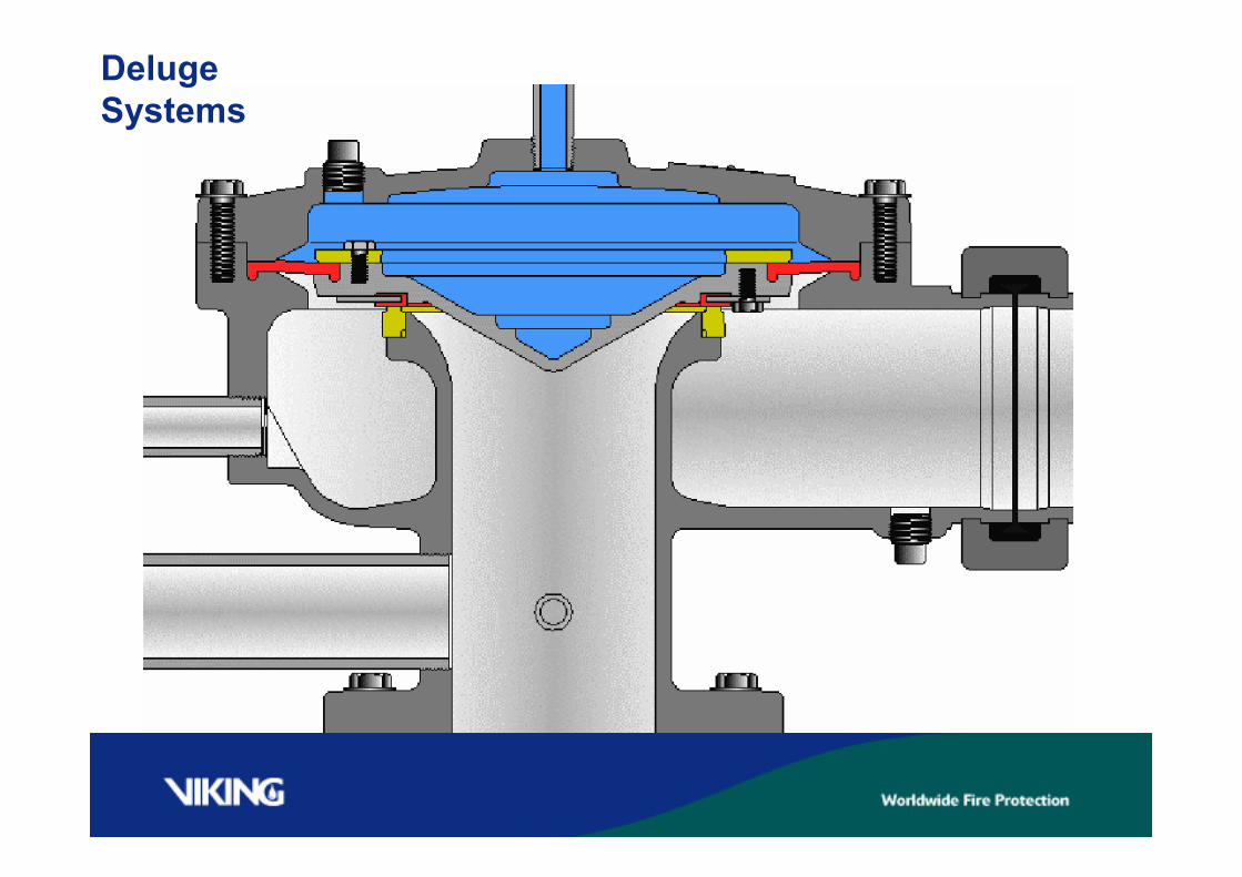
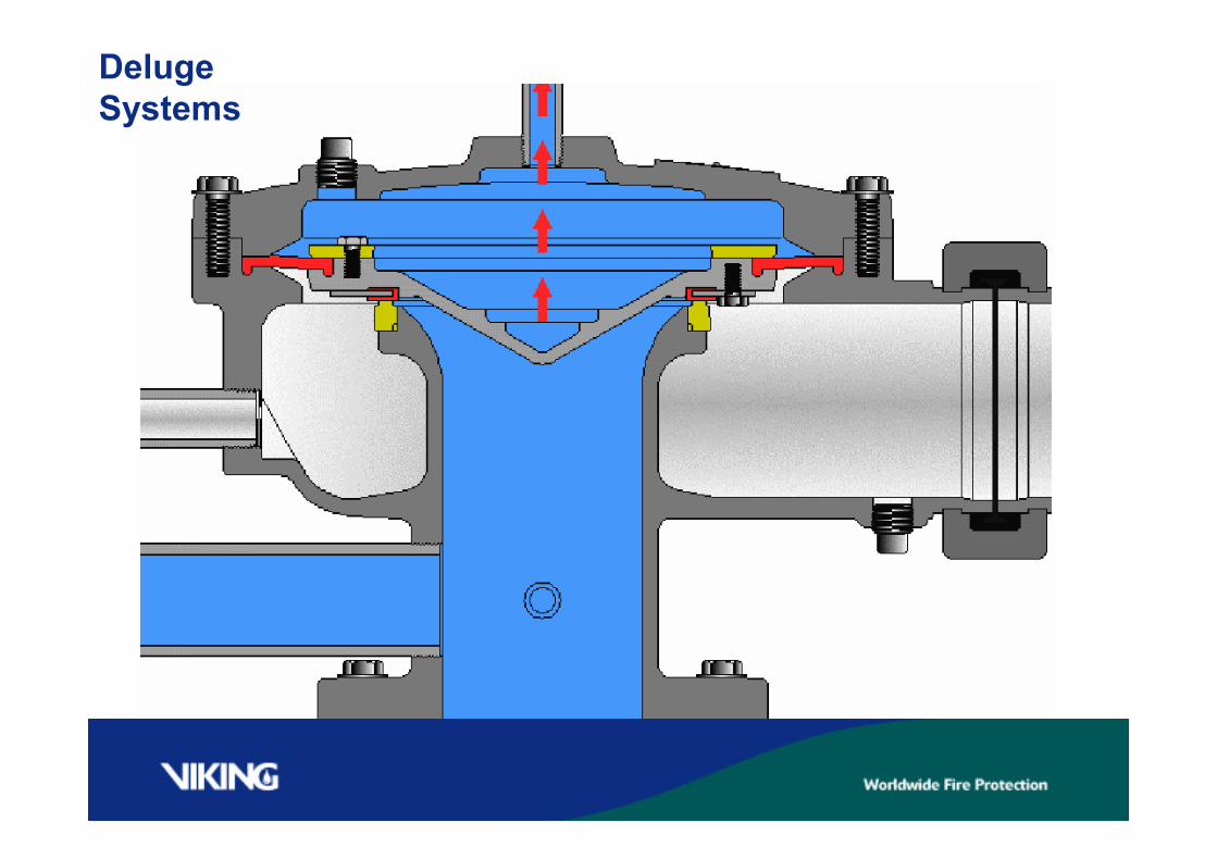
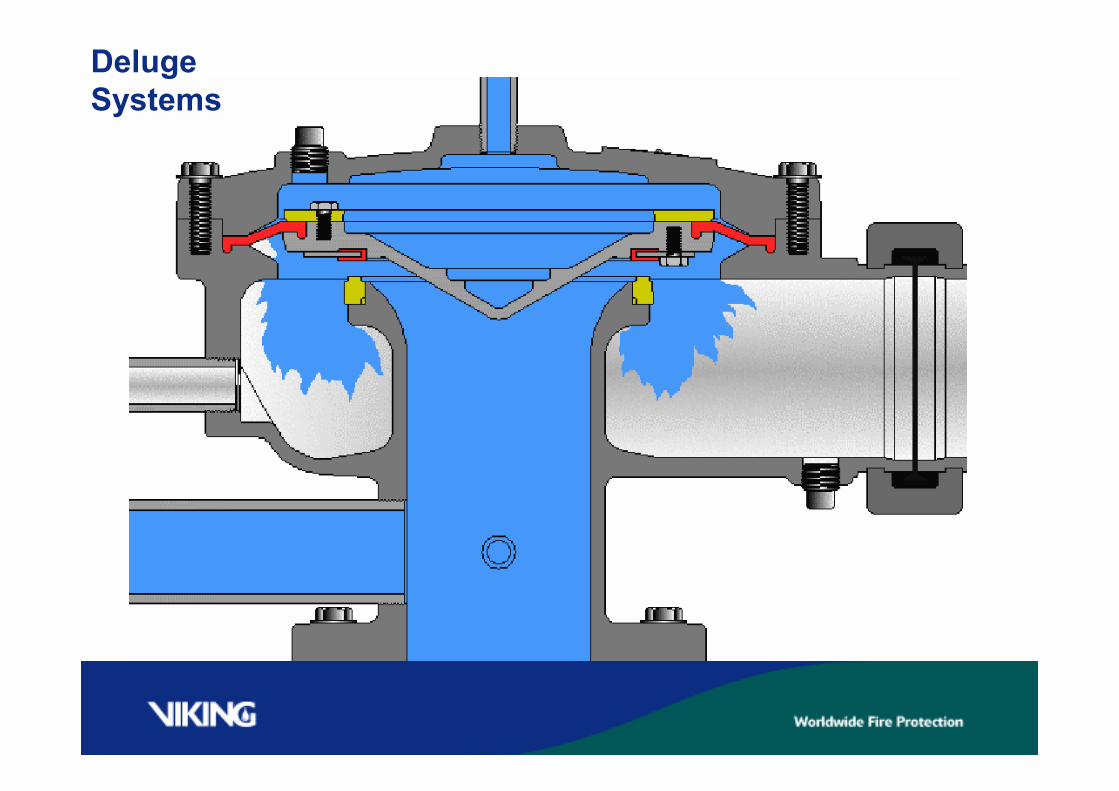
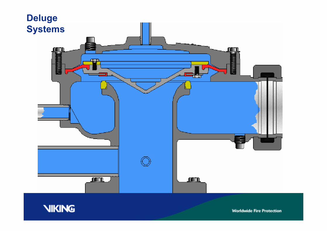
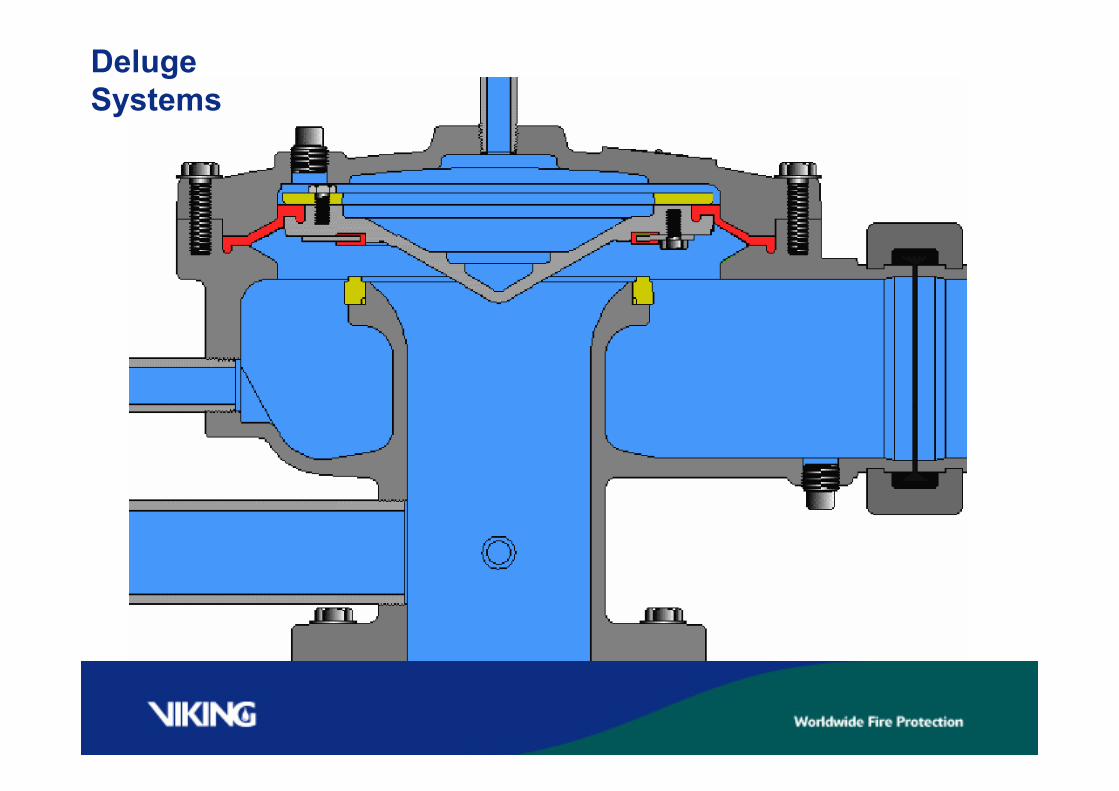
Deluge valves are held shut with pressurized water placedin the valve’s priming chamber. The priming chambercontrols a mechanism that keeps the deluge valve’s clapperclosed.The release system controls the water in the deluge valve’spriming chamber. When the release system operates, thepriming chamber is relieved of the priming water, allowingdeluge valve clapper to open.
Deluge Valves
The priming chamber has to be pressurized before the watercontrol valve can be opened, allowing water pressure againstthe deluge valve clapper. A connection has to be placedbefore the water control valve, so the deluge valve can beprimed. Once most deluge systems have operated, they haveto be manually shut down before they can be put back inservice.
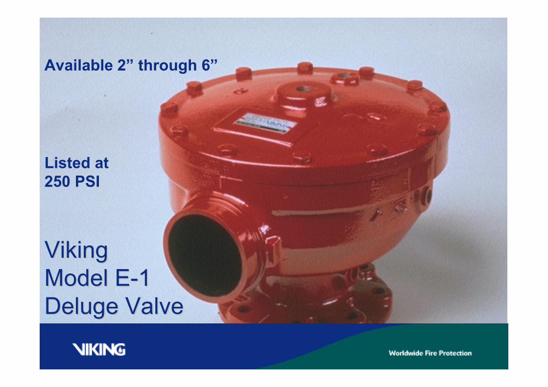
Listed at250 PSI
Available 2” through 6”
VikingVikingModel EModel E--11Deluge ValveDeluge Valve
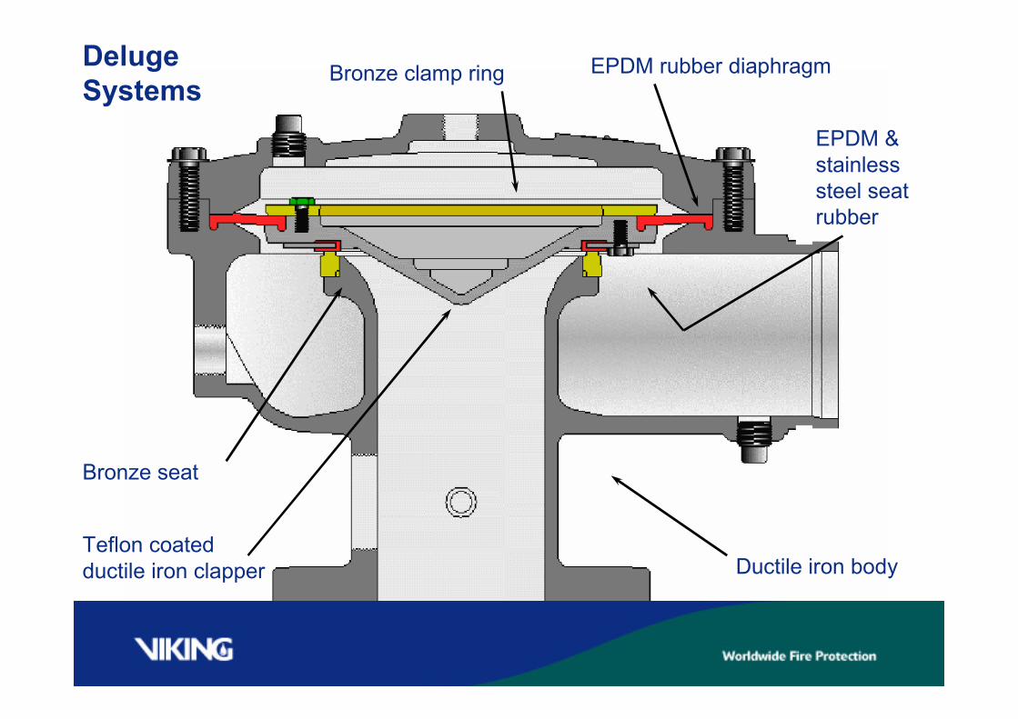
DelugeSystems
Bronze seat
EPDM rubber diaphragmBronze clamp ring
Teflon coatedductile iron clapper Ductile iron body
EPDM &stainlesssteel seatrubber

Priming chamber
Discharge oroutlet chamber
Inlet chamber
DelugeSystems
DelugeSystems
DelugeSystems

DelugeSystems
DelugeSystems
DelugeSystems
DelugeSystems
DelugeSystems
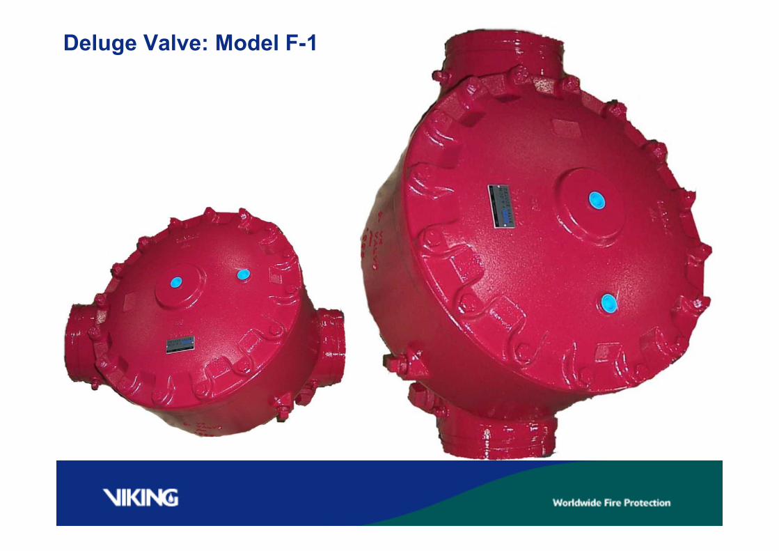
Deluge Valve: Model F-1
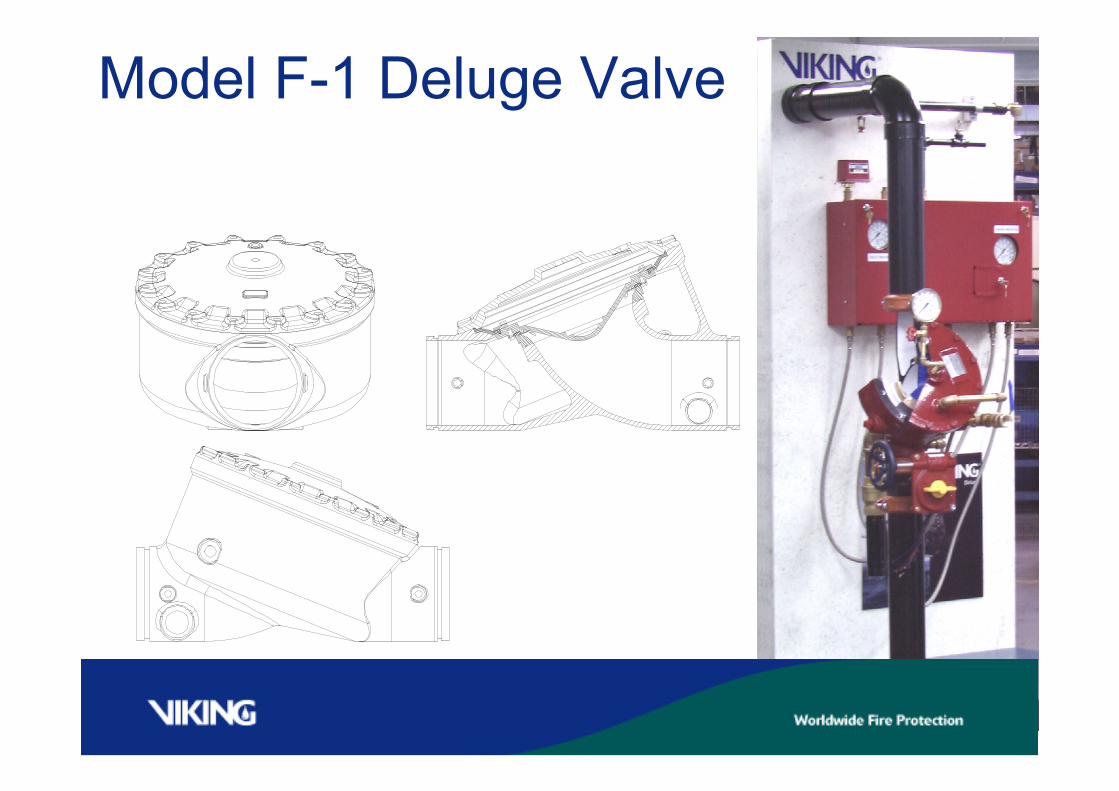
Model F-1 Deluge Valve
EZ DELUGE VALVE TRIM
•INSTALLATION &PURPOSE
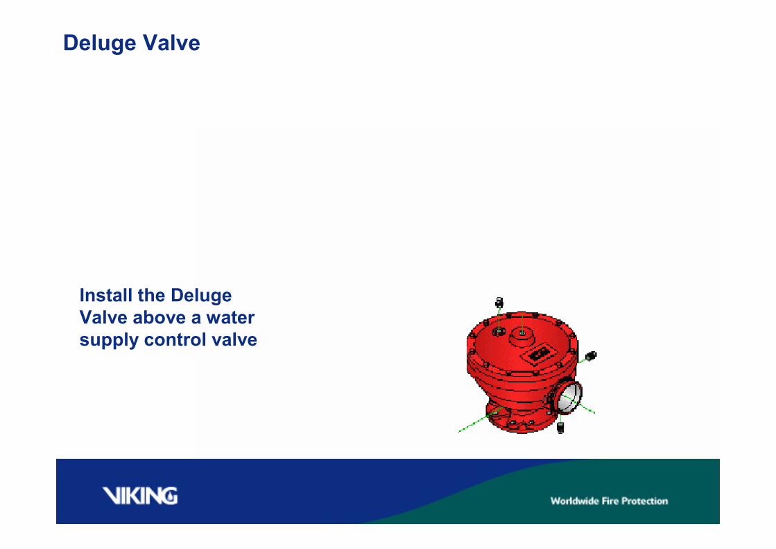
Deluge Valve
Install the DelugeValve above a watersupply control valve
Deluge Valve
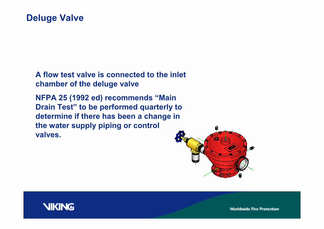
A flow test valve is connected to the inletchamber of the deluge valve
NFPA 25 (1992 ed) recommends “MainDrain Test” to be performed quarterly todetermine if there has been a change inthe water supply piping or controlvalves.
Deluge Valve
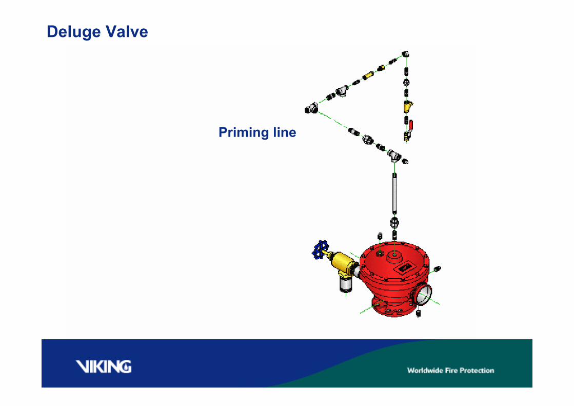
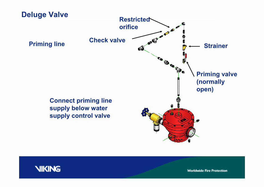
Priming line
Deluge Valve
Priming line
Connect priming linesupply below watersupply control valve
Strainer
Priming valve(normallyopen)
Restrictedorifice
Check valve
Deluge Valve Trim
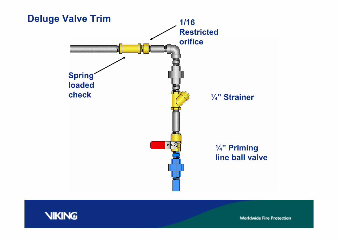
Springloadedcheck
1/16Restrictedorifice
¼” Strainer
¼” Primingline ball valve
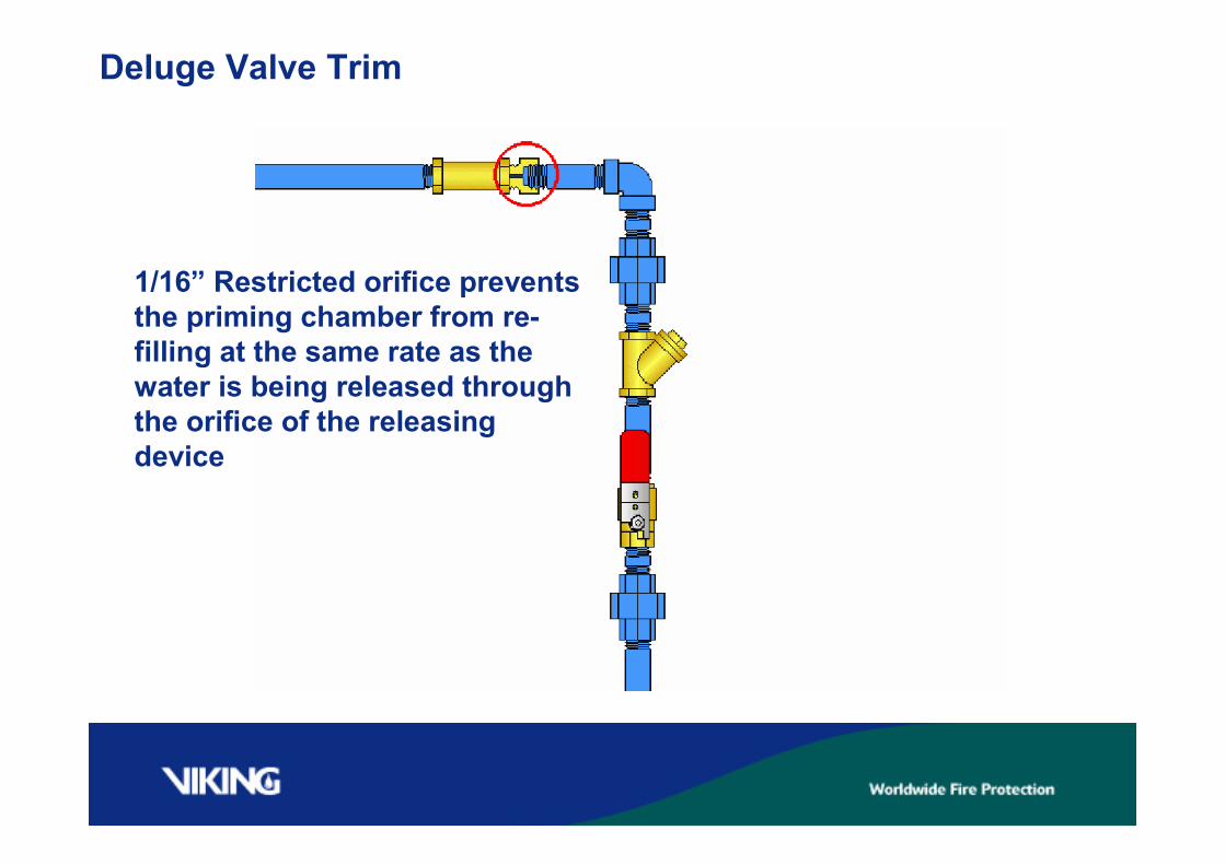
Deluge Valve Trim
1/16” Restricted orifice preventsthe priming chamber from re-filling at the same rate as thewater is being released throughthe orifice of the releasingdevice
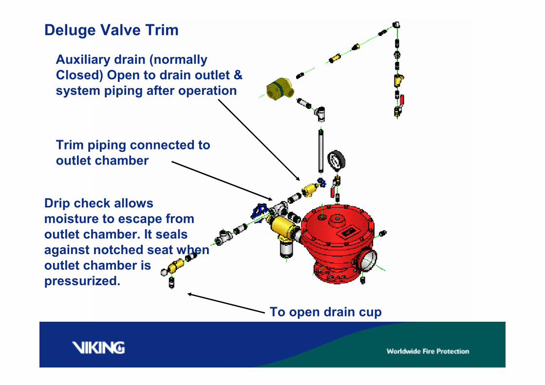
Deluge Valve Trim
Auxiliary drain (normallyClosed) Open to drain outlet &system piping after operation
Drip check allowsmoisture to escape fromoutlet chamber. It sealsagainst notched seat whenoutlet chamber ispressurized.
To open drain cup
Trim piping connected tooutlet chamber
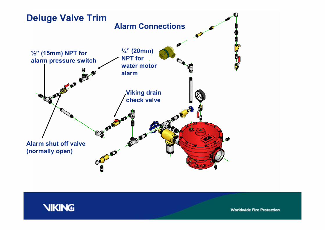
Deluge Valve Trim
½” (15mm) NPT foralarm pressure switch
Alarm shut off valve(normally open)
¾” (20mm)NPT forwater motoralarm
Viking draincheck valve
Alarm Connections
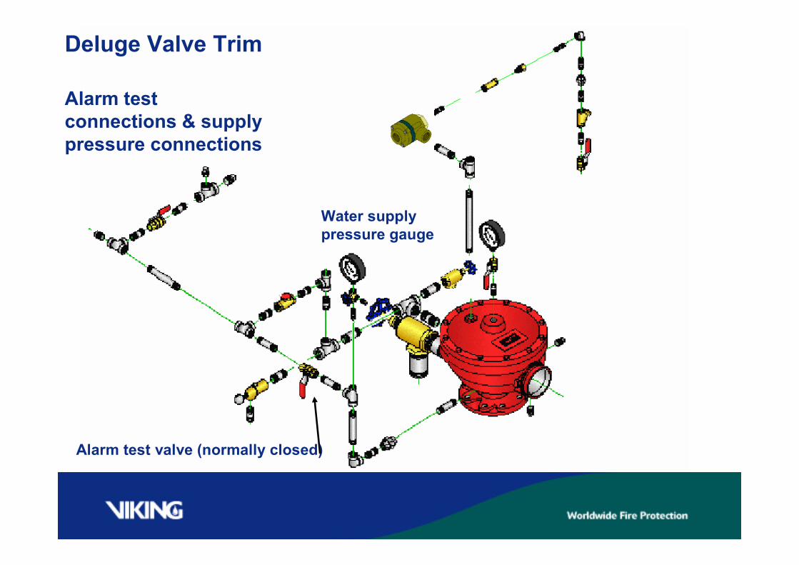
Deluge Valve Trim
Alarm testconnections & supplypressure connections
Water supplypressure gauge
Alarm test valve (normally closed)
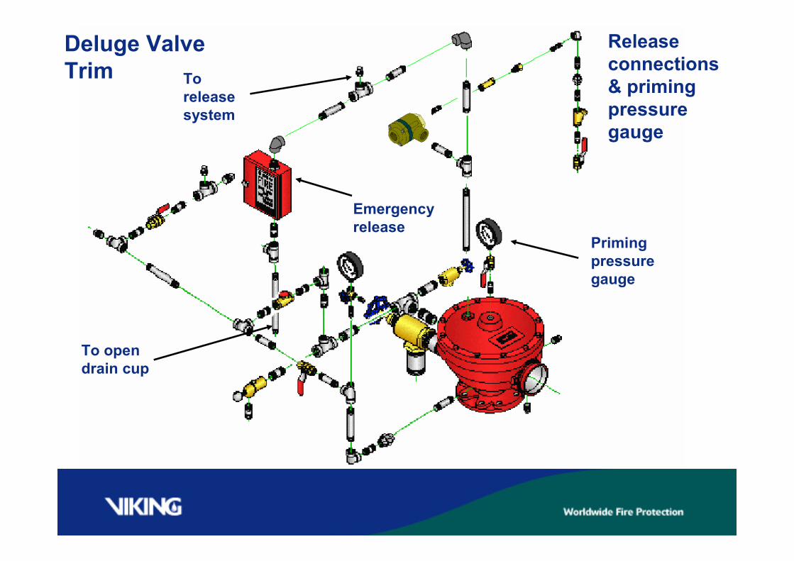
Deluge ValveTrim
To opendrain cup
Primingpressuregauge
Toreleasesystem
Emergencyrelease
Releaseconnections& primingpressuregauge
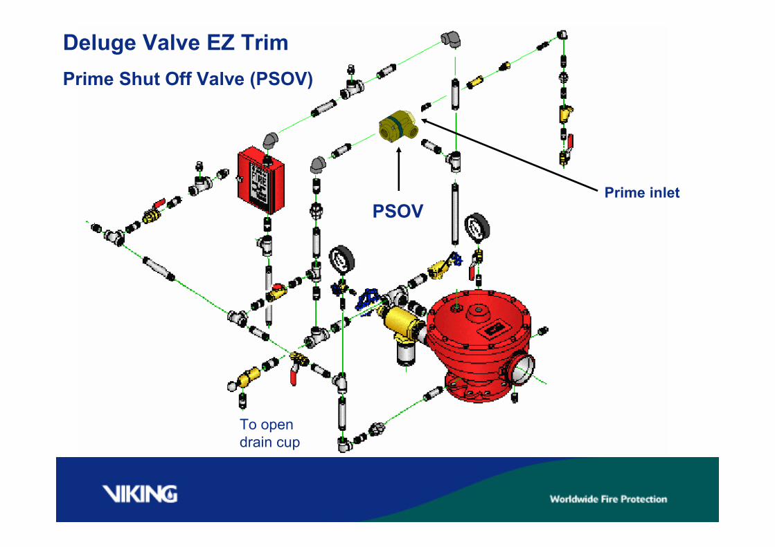
Deluge Valve EZ Trim
PSOV
To opendrain cup
Prime inlet
Prime Shut Off Valve (PSOV)
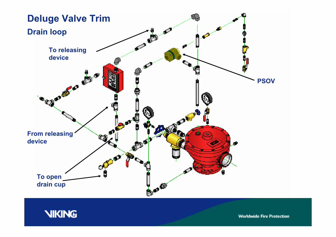
Deluge Valve TrimDrain loop
PSOV
To opendrain cup
To releasingdevice
From releasingdevice
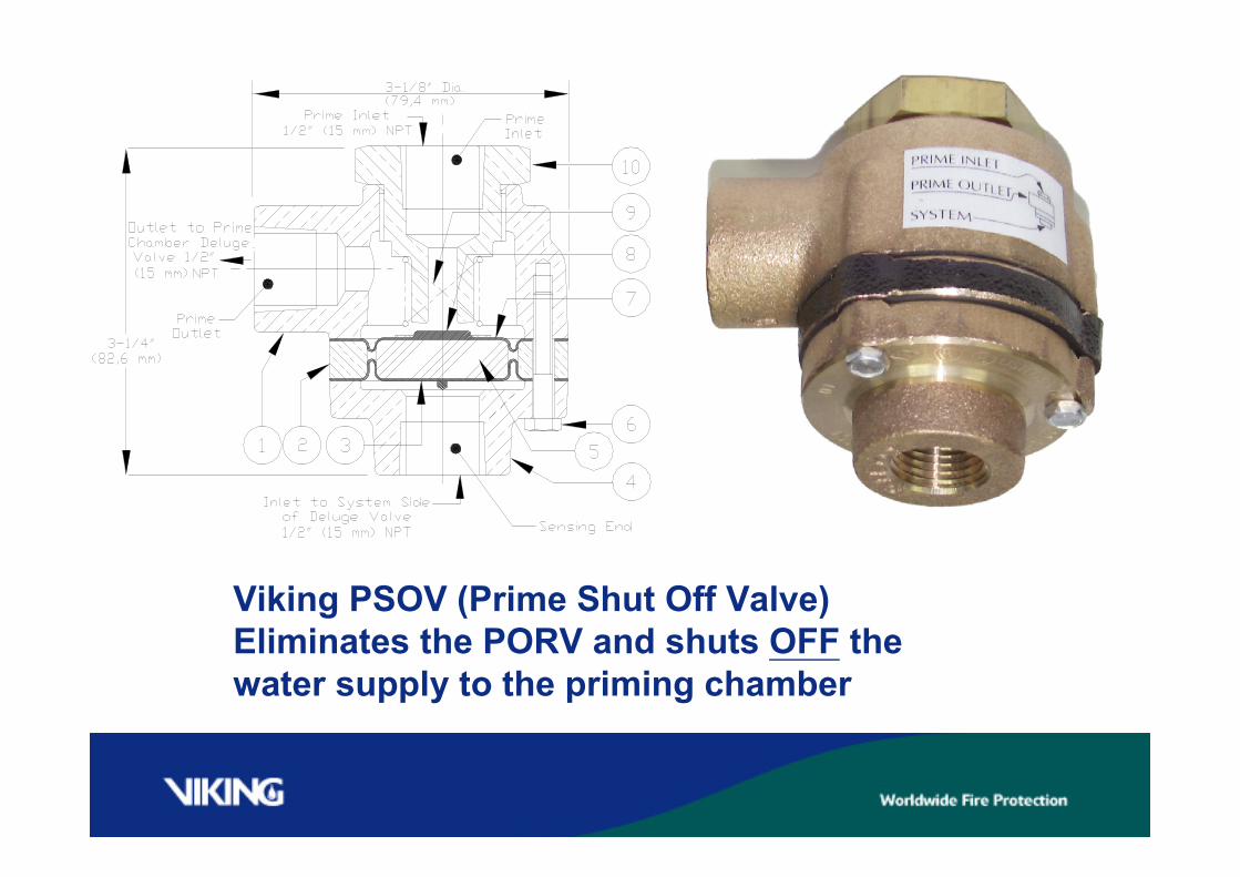
Viking PSOV (Prime Shut Off Valve)Eliminates the PORV and shuts OFF thewater supply to the priming chamber
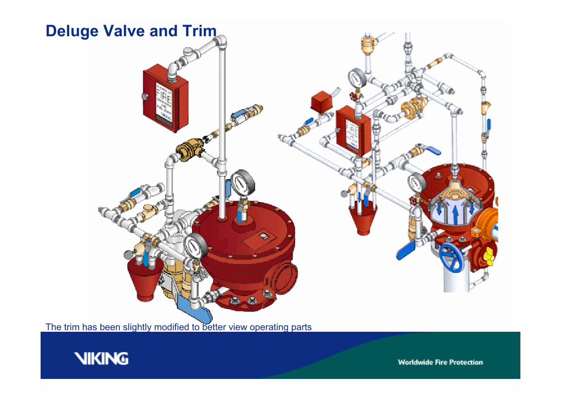
Deluge Valve and Trim
The trim has been slightly modified to better view operating parts

DelugeValve Trim To Release
system
WARNING!! Do not usethis trim for anyautomatically resettabledetection systems, or forpressure regulatingvalves!
When the hydraulic, electric, orpneumatic detection system hasoperated and the Viking delugevalve is tripped, the priming shutoff valve (PSOV) is activated asshown in the following animation.
The trim has been slightly modified to better view operating parts
DelugeSystems
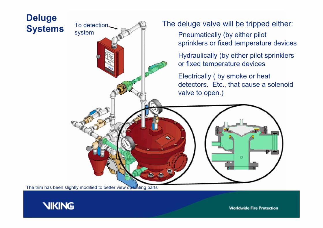
The trim has been slightly modified to better view operating parts
Pneumatically (by either pilotsprinklers or fixed temperature devices
The deluge valve will be tripped either:
Electrically ( by smoke or heatdetectors. Etc., that cause a solenoidvalve to open.)
Hydraulically (by either pilot sprinklersor fixed temperature devices
To detectionsystem
DelugeSystems
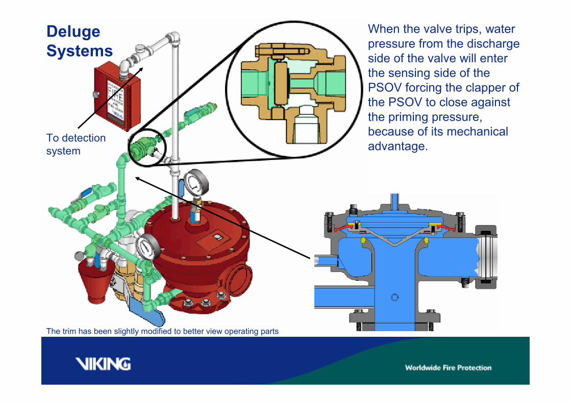
To detectionsystem
The trim has been slightly modified to better view operating parts
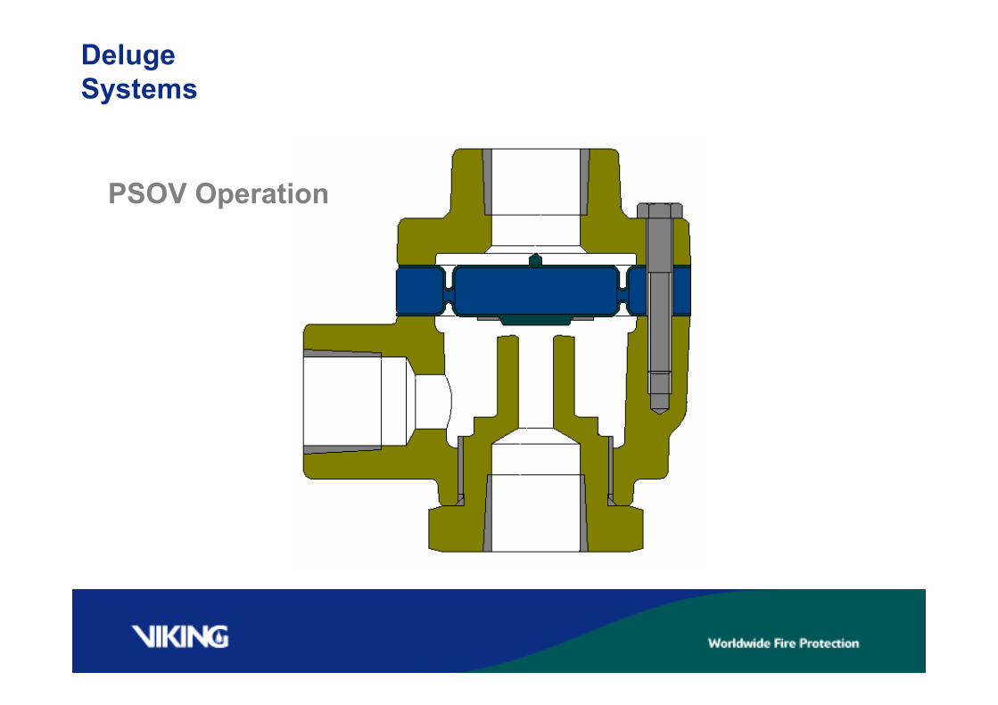
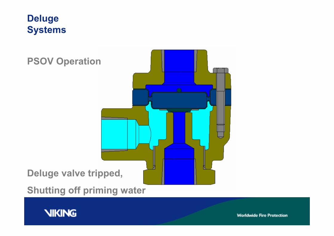
When the valve trips, waterpressure from the dischargeside of the valve will enterthe sensing side of thePSOV forcing the clapper ofthe PSOV to close againstthe priming pressure,because of its mechanicaladvantage.
DelugeSystems
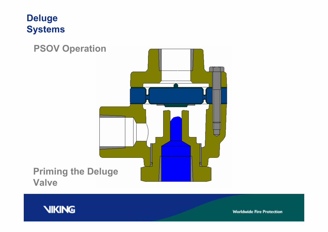
PSOV Operation
DelugeSystems
PSOV Operation
Priming the DelugeValve
DelugeSystems
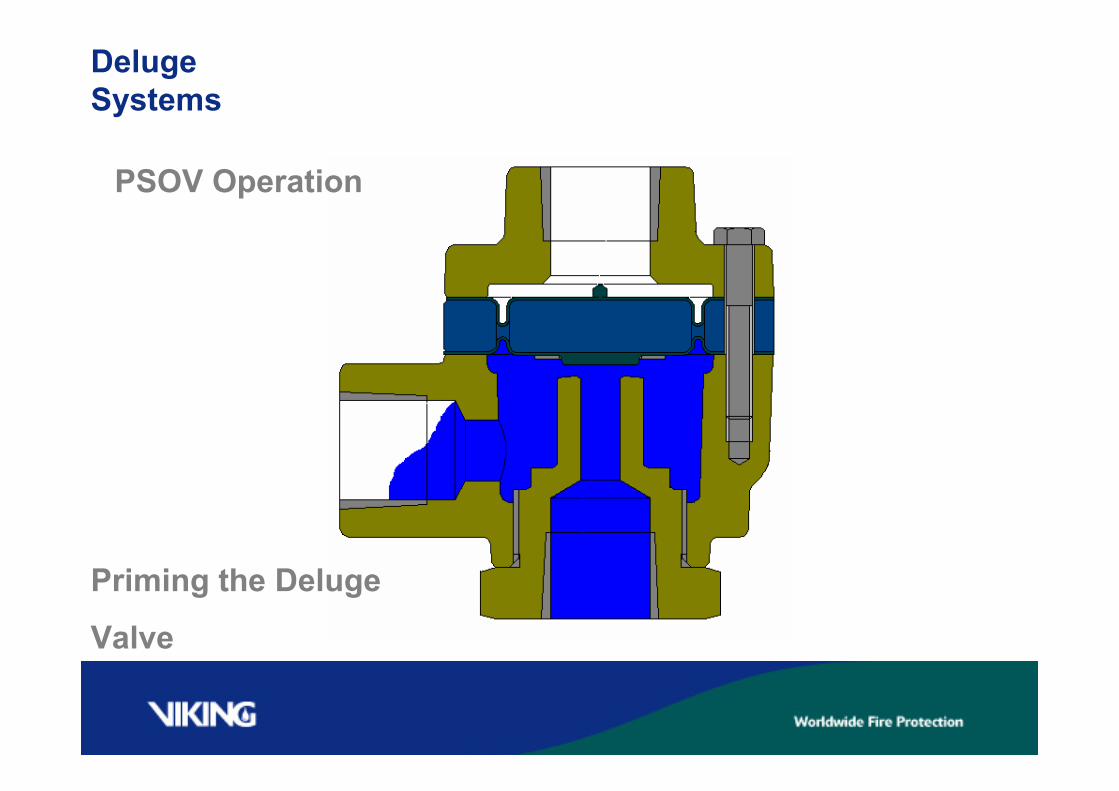
PSOV Operation
Priming the Deluge
Valve

DelugeSystems
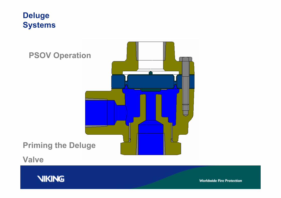
PSOV Operation
Priming the Deluge
Valve
DelugeSystems
PSOV Operation
Priming the Deluge
Valve
DelugeSystems
PSOV Operation
Deluge valve tripped,
Shutting off priming water
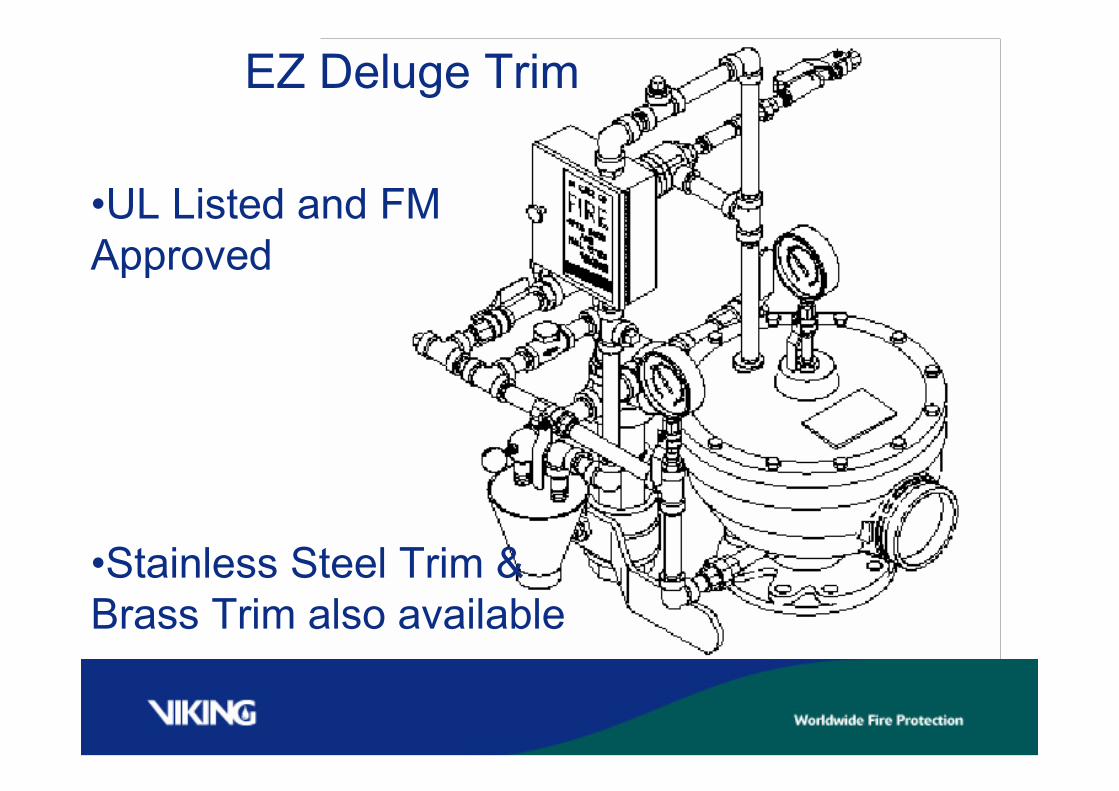
EZ Deluge Trim
•UL Listed and FMApproved
•Stainless Steel Trim &Brass Trim also available
SureFire Release Systems
We will discuss the SureFire release system as itpertains to the deluge valve and it’s trim
Deluge valves are held shut by their release system. In asingle interlocked SureFire pre-action system, we useone release module.
Electric Release
Electric release systems are the mostprevalent type of release systems. Electricrelease offers the most flexibility, as thedetection system can be configured in manyways, and the choices in release devices aregreater than hydraulic or pneumatic.
Solenoid Valves
Solenoid valves are described by their positionwhen non-powered:
1) Normally OpenWhen non-powered the solenoid valve isopen
2) Normally ClosedWhen non-powered the solenoid valve isclosed

Viking SureFireRelease Trim Module
Normally OpenSolenoid Valve
Normally ClosedSolenoid Valve
To pressurizedsystem piping
ReleaseSystems
Viking SureFireRelease Trim Module
24vdc Electric solenoid(normally open)
24vdc Electric solenoid(normally closed)
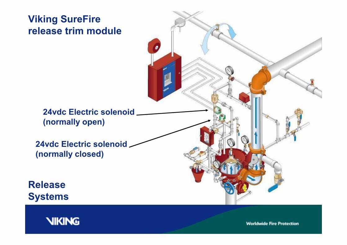
ReleaseSystems
Viking SureFirerelease trim module
24vdc Electric solenoid(normally open)
24vdc Electric solenoid(normally closed)
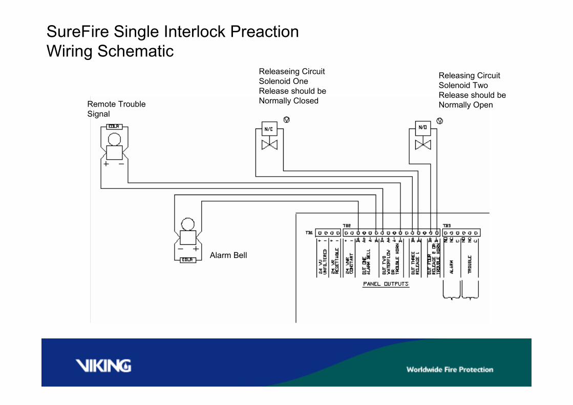
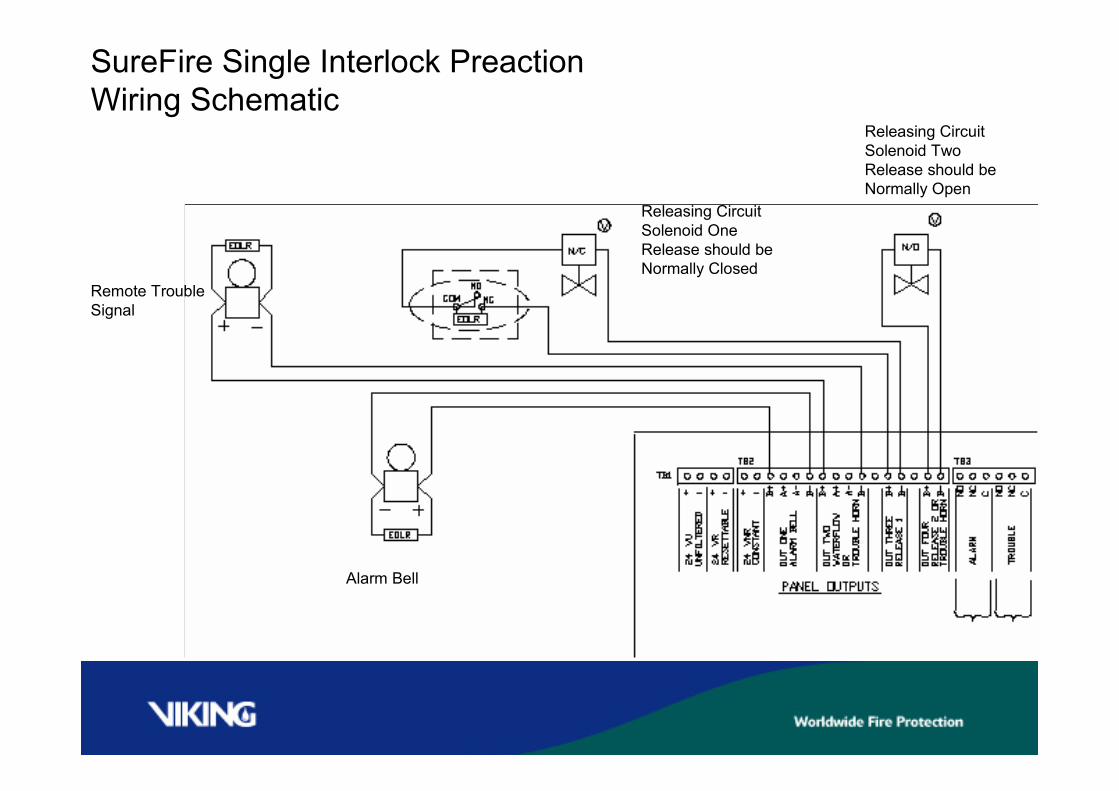
Releasing CircuitSolenoid TwoRelease should beNormally Open
Alarm Bell
Remote TroubleSignal
Releaseing CircuitSolenoid OneRelease should beNormally Closed
SureFire Single Interlock PreactionWiring Schematic
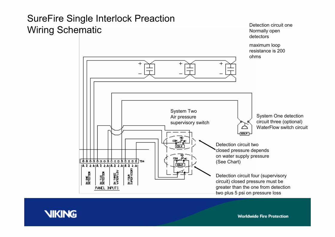
System TwoAir pressuresupervisory switch
Detection circuit oneNormally opendetectors
maximum loopresistance is 200ohms
SureFire Single Interlock PreactionWiring Schematic
System One detectioncircuit three (optional)WaterFlow switch circuit
Detection circuit twoclosed pressure dependson water supply pressure(See Chart)
Detection circuit four (supervisorycircuit) closed pressure must begreater than the one from detectiontwo plus 5 psi on pressure loss
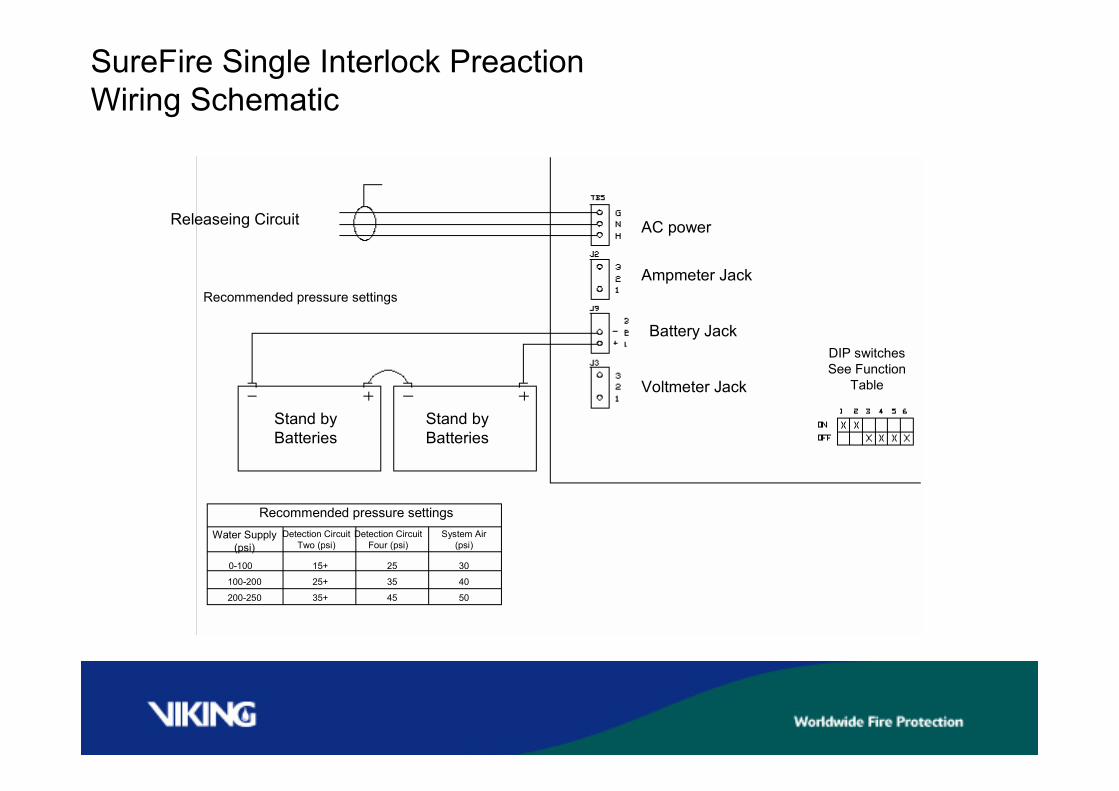
Stand byBatteries
Releaseing Circuit
SureFire Single Interlock PreactionWiring Schematic
AC power
Ampmeter Jack
Battery Jack
Voltmeter Jack
Recommended pressure settingsWater Supply
(psi)
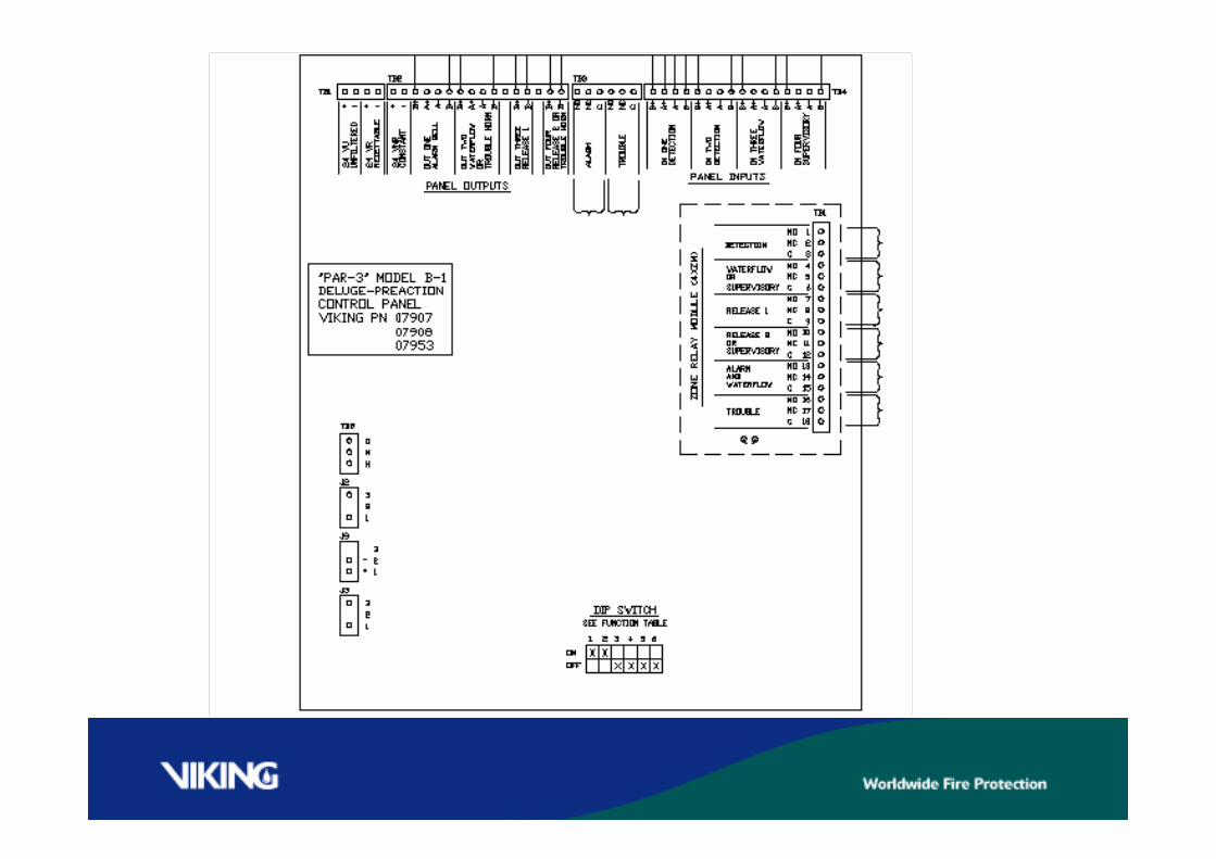
DIP switchesSee Function
Table
Recommended pressure settings
Detection CircuitTwo (psi)
Detection CircuitFour (psi)
35+
System Air(psi)
25+
15+
200-250
100-200
0-100
50
40
30
45
35
25
Stand byBatteries

Par 3 Release Panel Function Table
SureFire Single Interlock PreactionWiring Schematic
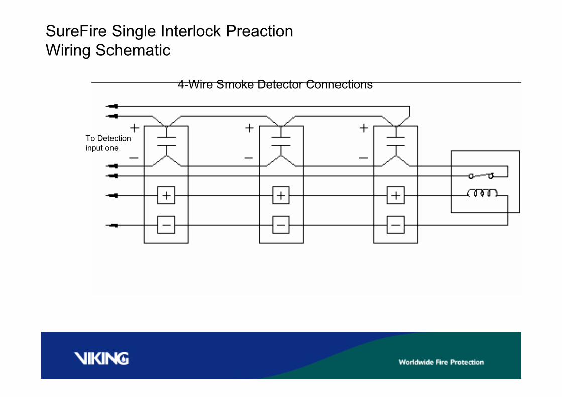
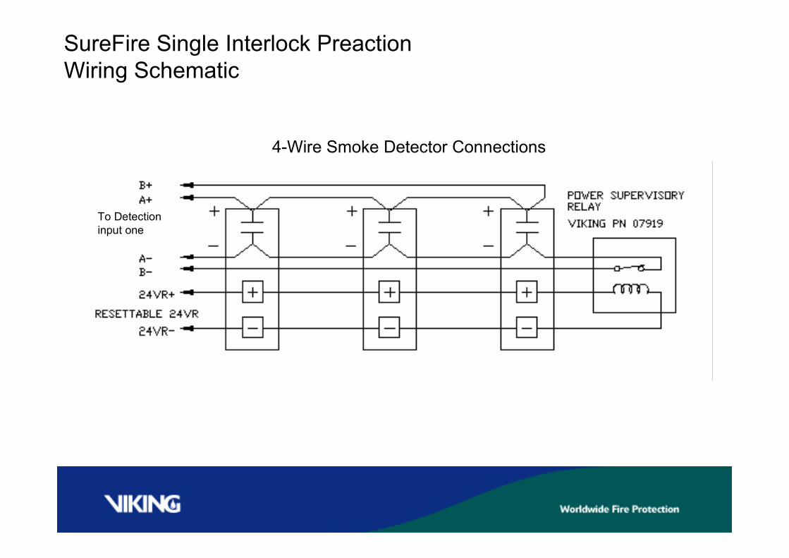
To Detectioninput one
4-Wire Smoke Detector Connections
SureFire Single Interlock PreactionWiring Schematic
Viking SureFireDouble Interlocked
Pre-action
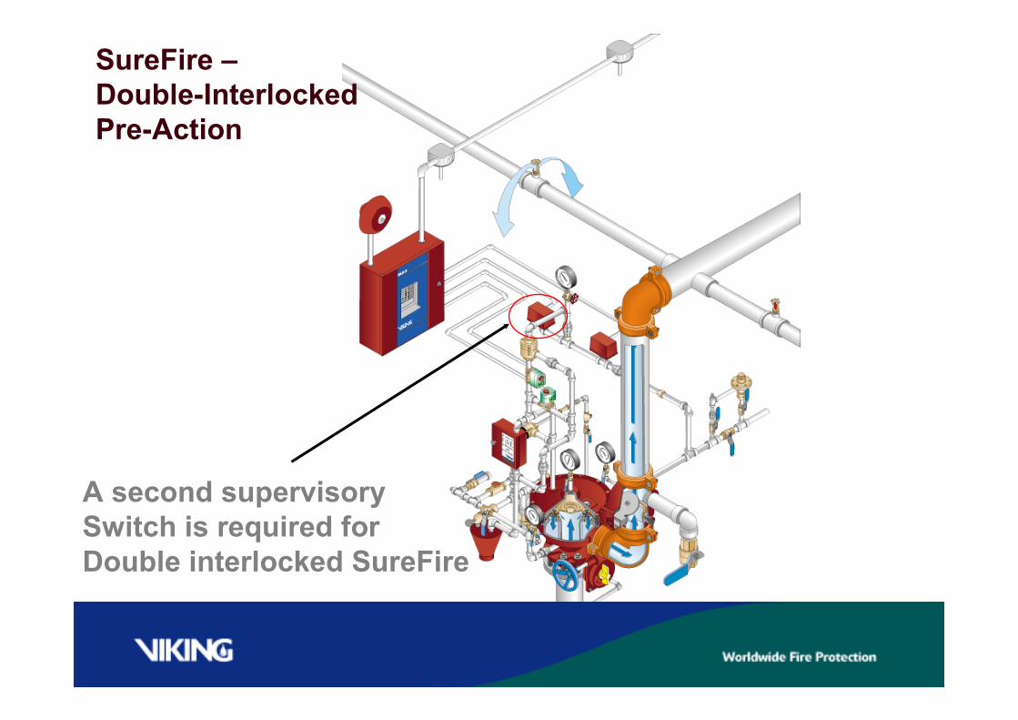
A second supervisorySwitch is required forDouble interlocked SureFire
SureFire –Double-InterlockedPre-Action
The Release System must activate …..-(an alarm will sound)-AND,-Pressure in the sprinkler piping must be reduced-(due toa sprinkler opening in fire conditions) To trip open theDeluge Valve.
In fire conditions,- After the release system operates and the sprinkleropens, water needs to travel from the Deluge Valve to theopen sprinkler.There may be a time delay similar to a Dry System.
DOUBLE INTERLOCKED OPERATION
The Release System must activate …..-(an alarm will sound)-AND,-Pressure in the sprinkler piping must be reduced-(due toa sprinkler opening in fire conditions)
To trip open the Deluge Valve.In fire conditions,- After the release system operates and the sprinkleropens, water needs to travel from the Deluge Valve to theopen sprinkler.There may be a time delay similar to a Dry System.
DOUBLE INTERLOCKED OPERATION
SureFire release trim is the same for either single ordouble interlocked pre-action. Double interlockedSureFire requires a second supervisory switch in the airsupply line to the riser.
The second supervisory switch operates the normallyclosed solenoid valve only after the detection circuit hasoperated. Both the detection and air pressure has to belost prior to the normally closed solenoid operating.
DOUBLE INTERLOCKED OPERATION
Viking SureFireRelease Trim Module
Normally OpenSolenoid Valve
Normally ClosedSolenoid Valve
To pressurizedsystem piping
Remote TroubleSignal
Releasing CircuitSolenoid OneRelease should beNormally Closed
SureFire Single Interlock PreactionWiring Schematic
Alarm Bell
Releasing CircuitSolenoid TwoRelease should beNormally Open
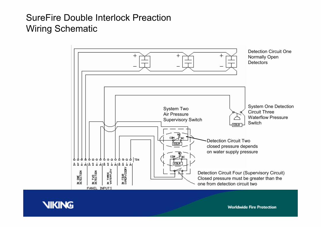
System TwoAir PressureSupervisory Switch
Detection Circuit OneNormally OpenDetectors
SureFire Double Interlock PreactionWiring Schematic
Detection Circuit Twoclosed pressure dependson water supply pressure
System One DetectionCircuit ThreeWaterflow PressureSwitch
Detection Circuit Four (Supervisory Circuit)Closed pressure must be greater than theone from detection circuit two
To Detectioninput one
4-Wire Smoke Detector Connections
SureFire Single Interlock PreactionWiring Schematic
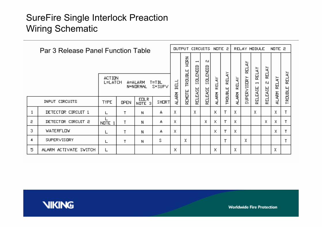
Par 3 Release Panel Function Table
SureFire Single Interlock PreactionWiring Schematic
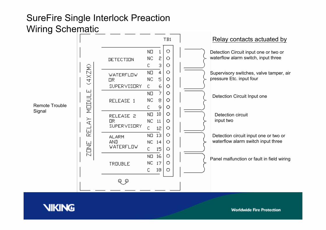
Remote TroubleSignal
Relay contacts actuated by
SureFire Single Interlock PreactionWiring Schematic
Detection circuit input one or two orwaterflow alarm switch input three
Detection circuitinput two
Detection Circuit Input one
Supervisory switches, valve tamper, airpressure Etc. input four
Detection Circuit input one or two orwaterflow alarm switch, input three
Panel malfunction or fault in field wiring

Thank You