virtualized enterprise
TRANSCRIPT
8/6/2019 Virtualized Enterprise
http://slidepdf.com/reader/full/virtualized-enterprise 1/19
C H A P T E R
3
A Basic Virtualized Enterprise
In this chapter, we define the technical requirements posed by the need to virtualize the
network. Based on these requirements, we propose and architectural framework comprised
of the functional areas necessary to successfully support concurrent virtual networks (VNs)
over a shared enterprise physical network.
Networks enable users to access services and resources distributed throughout the enterprise.
Some of these services and resources are public: those accessed over the Internet, and
others that are private and internal to the enterprise. Every enterprise has unique security and
service level policies that govern the connectivity to the different services, whether these are
public or private.
One of the basic building blocks behind the virtualized network and, in fact, a key driver is
security. An important element of an enterprise’s security policy is the definition of a
network perimeter. In general, the level of trust inside and outside of the network perimeter
differs, with end stations inside the perimeter being generally trusted and any access from
outside the perimeter being untrusted by default. Communications between the inside
and the outside of the perimeter must happen through a checkpoint. At the checkpoint,
firewalls and other security devices ensure that all traffic that enters or leaves the enterprise
is tightly controlled. Therefore, we refer to the point of entry/exit to/from the enterprise
network as the network perimeter.
NOTE The network perimeter defines one layer of security and must be complemented with other
security mechanisms. It is critical to incorporate mechanisms to protect the network from
attacks initiated inside the perimeter. This functionality is generally provided at the network
access/edge and is not impacted by the virtualization of the network.
To provide the required connectivity, create a secure perimeter and enforce the necessary
policies, it is recommended that an enterprise network be based on certain functional blocks.
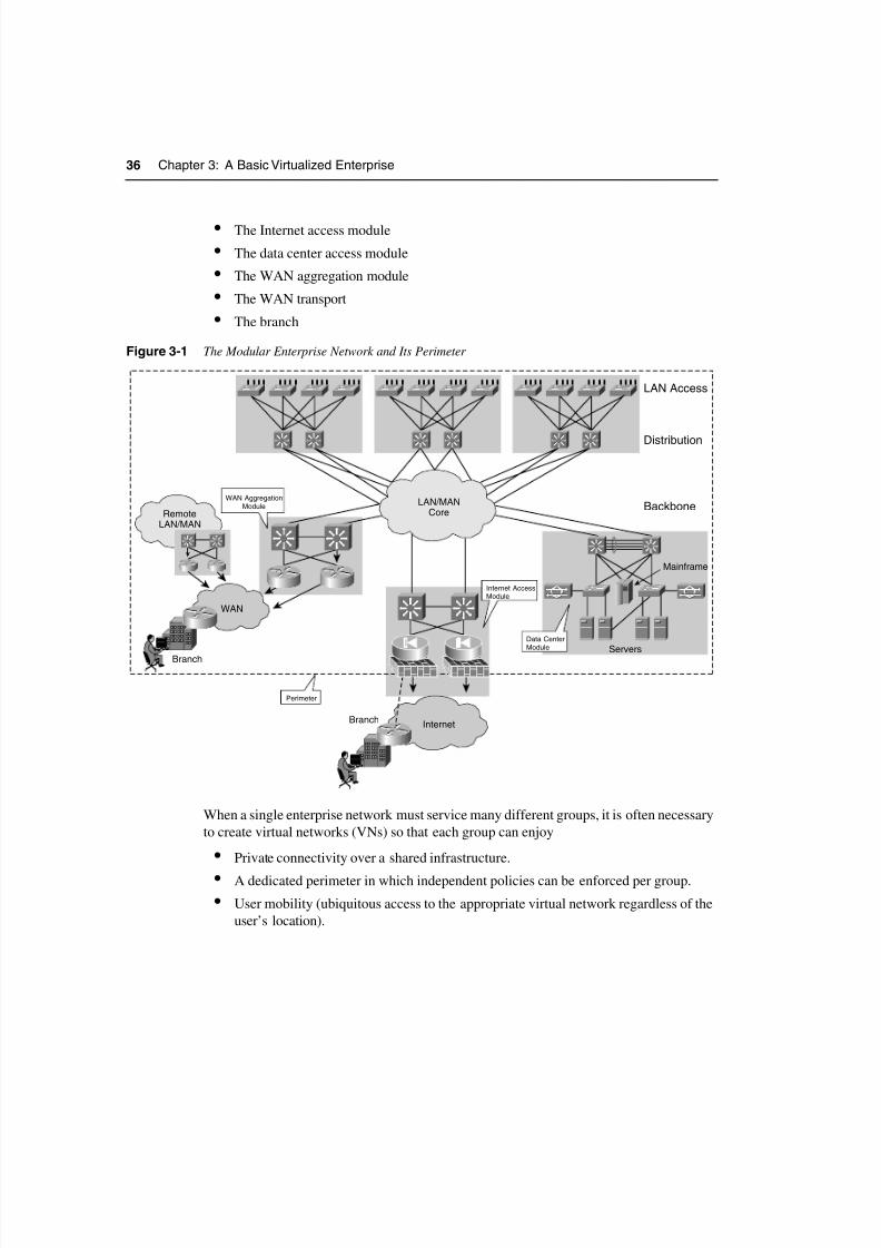
Figure 3-1 depicts a modular enterprise network and its perimeter. The recommended
functional blocks are as follows:
• The LAN/MAN transport (core and distribution)
• The LAN edge or access layer
8/6/2019 Virtualized Enterprise
http://slidepdf.com/reader/full/virtualized-enterprise 2/19
36 Chapter 3: A Basic Virtualized Enterprise
• The Internet access module
• The data center access module
• The WAN aggregation module
• The WAN transport
• The branch
Figure 3-1 The Modular Enterprise Network and Its Perimeter
When a single enterprise network must service many different groups, it is often necessary
to create virtual networks (VNs) so that each group can enjoy
• Private connectivity over a shared infrastructure.
• A dedicated perimeter in which independent policies can be enforced per group.
• User mobility (ubiquitous access to the appropriate virtual network regardless of the
user’s location).
Distribution
LAN Access
BackboneWAN Aggregation
Module
Internet AccessModule
Perimeter
LAN/MANCore
Internet
WAN
Branch
Branch
Mainframe
ServersData CenterModule
RemoteLAN/MAN

8/6/2019 Virtualized Enterprise
http://slidepdf.com/reader/full/virtualized-enterprise 3/19

8/6/2019 Virtualized Enterprise
http://slidepdf.com/reader/full/virtualized-enterprise 4/19
38 Chapter 3: A Basic Virtualized Enterprise
zone relies on traffic-isolation mechanisms rather than a distributed policy. Because
traffic internal to a zone is trusted, policies are required only at the perimeter to
control the access to external resources that could in many cases be shared. Figure 3-2
illustrates this concept.
Figure 3-2 Virtual Networks with Centralized Policies at the Perimeter
Regardless of where a user is connected, its traffic should always use the same VN and be
directed through a central site of policy enforcement (VN perimeter), should it need to exit
the VN. This makes users mobile and ensures that regardless of their location they willalways be subject to the same policies. To ensure that users are always connected to the right
VN, dynamic authentication and authorization mechanisms are required. These allow the
identification of devices, users, or even applications so that these can be authorized onto the
correct virtual segment and thus inherit the segment’s policies.
The virtualization architecture described so far can be organized into functional areas.
These functional areas provide a framework for the virtualization of networks:
• Transport virtualization
• Edge authorization
• Central services access (VN perimeter)
As you will see throughout the book, this modular framework gives the network architect
a wide choice of technologies for each functional area. A key element in achieving thisdegree of flexibility is the definition of clear communication interfaces between the
different areas.
VLANs provide an example of a communication interface between functional areas.
The edge authorization module assigns a user to a VLAN, and the transport module maps
Internet
Gateway
Perimete
rOutside Perime
terInside
Video
Server
Hosted
Content
DHCP
IPSec
Gateway
Firewall
and NAT

8/6/2019 Virtualized Enterprise
http://slidepdf.com/reader/full/virtualized-enterprise 5/19
The Virtual Enterprise 39
that VLAN to a VN. At the destination, the transport module maps the VPN back to a
VLAN. If the destination is outside the VN perimeter, the transport module hands off
a VLAN to the central services access module, which maps the VLAN to the necessary
virtual services. As you progress through the book, you learn that the interface between
modules could very well be a label or a policy.
NOTE There are, of course, pros and cons to using different types of communication interfaces.
These are analyzed as the different technologies are discussed in detail, so read on.
Figure 3-3 shows the functional areas of the virtualized enterprise. As shown, you can usea variety of technologies for each different area.
Figure 3-3 Virtualized Enterprise Network Functional Areas
Mainframe
Servers
MAN/WAN
L3 VRFs
802.1Q + VRFsMPLS VPNs
GRE, L2TPv3
VLANs PartitionServer Farms
Authorize peruser/role VLANs
User identification(802.1x, etc.)
VN Perimeter
EdgeAuthorization
802.1Q + VRFsMPLS VPNs
GRE, L2TPv3,DMVPN, DGVPN
Virtualized Services:FW, CSM
TransportVirtualization
TransportVirtualization

8/6/2019 Virtualized Enterprise
http://slidepdf.com/reader/full/virtualized-enterprise 6/19
40 Chapter 3: A Basic Virtualized Enterprise
A useful way to look at Figure 3-3 and understand the role of the different functional
areas is to look at it from the top down. Starting at the top, the endpoints connected to
the network are authenticated and as a result of the authentication are authorized onto a
specific VLAN (edge authorization). Each VLAN maintains its traffic separate from other
VLANs and is mapped to a virtual routing and forwarding instance (VRF).
NOTE VRFs are logical routing and forwarding tables with associated interfaces and routing
processes, what could be thought of as a virtual routing instance. The section on
“Control-Plane-Based Segmentation” and Chapter 4 examine the concept of a VRF in
more detail.
Each VRF is connected to other VRFs in its VN and keeps its traffic separate from VRFs
that belong to other VNs (transport virtualization). When traffic is destined to a resource
outside the VN (for example, the data center), it is routed to the VN perimeter, where virtual
services, such as firewalling and load balancers, are applied to each group (central services
access—VN perimeter). Traffic destined to a subnet over the WAN is kept separate from
traffic in other VNs through the virtualization of the WAN transport (transport
virtualizaton).
Transport Virtualization—VNs
When segmenting the network pervasively, all the scalability, resiliency, and securityfunctionality present in a nonsegmented network must be preserved and in many cases
improved. As the number of groups sharing a network increases, the network devices must
handle a much higher number of routes. Any technologies used to achieve virtualization
must therefore provide the necessary mechanisms to preserve resiliency, enhance
scalability, and improve security.
Chapter 2, “Designing Scalable Enterprise Networks,” discussed network design
recommendations that provide high availability and scalability through a hierarchical and
modular design. Much of the hierarchy and modularity discussed relies on the use of a
routed core. Nevertheless, some areas of the network continue to benefit from the use of
Layer 2 technologies, such as VLANs, ATM, or Frame Relay circuits. Thus, a hierarchical
IP network is a combination of Layer 3 (routed) and Layer 2 (switched) domains. Both
the Layer 2 and the Layer 3 domains must be virtualized, and the virtualized domains
must be mapped to each other to create VNs.
8/6/2019 Virtualized Enterprise
http://slidepdf.com/reader/full/virtualized-enterprise 7/19

8/6/2019 Virtualized Enterprise
http://slidepdf.com/reader/full/virtualized-enterprise 8/19
42 Chapter 3: A Basic Virtualized Enterprise
For example, providing virtual firewall services requires Layers 2, 3, and 4 virtualization,
plus the ability to define independent services and management on each virtual firewall,
which some may argue is Layer 7 virtualization. We delve into firewall virtualization in
Chapter 4. For now, we focus on the virtualization of the transport at Layers 2 and 3.
VLANs and ScalabilityTime and experience have proven the scalability benefits of limiting the size of Layer 2
domains in a network. A large amount of this experience comes from campus networks,
where highly resilient topologies with redundant links are possible. This link redundancy
intrinsically creates network loops that must be controlled by mechanisms such as spanning
tree. The broadcast nature of a Layer 2 domain is the main reason these redundant links
behave as loops rather than redundant active paths capable of load balancing. Hence, the
lack of load balancing and the complexity involved in managing large and highly resilient
spanning-tree domains makes a routed infrastructure much more appropriate for large-scale
highly available networks. Thus, experience has taught us that meshed Layer 2 domains
have their role in the network, but they must be kept small in scale. Keep in mind that we
are referring to highly meshed resilient Layer 2 domains such as those you would find in a
campus. This type of problem is faced less in the WAN, where point-to-point connections
tend to be at the base of the architecture and are for the most part routed. Nevertheless, the
introduction of technologies that extend Layer 2 domains over an IP infrastructure has
brought many of the spanning-tree concerns to the table in the metro-area network (MAN)
and WAN.
When you are virtualizing a network, it is tempting to revisit ideas such as end-to-end
VLANs. After all, mapping a group of users to a specific VLAN to create an isolatedworkgroup was one of the original thoughts behind the creation of VLANs. Should the
VLAN traverse the entire enterprise, we could say the transport has been virtualized. This
type of solution will have all the scalability problems associated with large Layer 2 domains
and is therefore not desirable.
Nevertheless, the use of VLANs has its place as a way of segmenting the Layer 2 portion
of the network. In an enterprise campus, this is generally the mesh of links between
the access and the distribution. Remember, the recommendation is to reduce the size of the
broadcast domains to something manageable, not necessarily to eliminate the broadcast
domains, because too much IP subnet granularity would also represent a management
challenge. So, to segment the access portion of the network, VLANs are of much use.
NOTE Later on, in the section “Policy-Based Segmentation,” you will see that there are
mechanisms to achieve traffic differentiation by using code points. These techniques do not
create separate broadcast domains and are effective only after entering the routed core. The
use of code points will not provide separation between groups that share a broadcast
domain. VLANs are required to provide Layer 2 separation at the access.
8/6/2019 Virtualized Enterprise
http://slidepdf.com/reader/full/virtualized-enterprise 9/19
Transport Virtualization—VNs 43
The network must preserve its hierarchy and therefore its routed core. As the periphery
(access/distribution) continues to be switched (as opposed to routed), VLANs must be used
for segmentation purposes. Thus, a VLAN in a wiring closet would represent the point of
entry into a VN.
Because these VLANs are terminated as they reach the routed core, it is necessary to map
them to segments created in the routed core. The next section looks into what is necessary
in the core. From the access perspective, the VLANs must map to the corresponding
segments created in the core to achieve an end-to-end VPN that spans both the switched and
routed portions of the network.
We focus our analysis on a network with a routed core and a switched access. This model
is widely adopted because it has been proven, optimized, and recommended by Cisco for
many years.
Virtualizing the Routed CoreYou can achieve the virtualization of the routed portion of the network in many ways. At
the device level, the available traffic separation mechanisms can be broadly classified as
follows:
• Policy-based segmentation
• Control-plane-based virtualization
Policy-Based Segmentation
Policy-based segmentation restricts the forwarding of traffic to specific destinations, basedon a policy and independently of the information provided by the control plane. The
policies are applied onto a single IP routing space. A classic example of this uses an access
control list (ACL) to restrict the valid destination addresses to subnets in the VN.
Policy-based segmentation is limited by two main factors:
• Policies must be configured pervasively.
• Locally significant code points are currently used for policy selection.
The configuration of distributed policies can be a significant administrative burden, is error
prone, and causes any update in the policy to have widespread impact.
The code point used for policy selection has traditionally been an IP address and therefore
locally significant. Because of the diverse nature of IP addresses, and because policies must
be configured pervasively, building policies based on IP addresses does not scale well. Thus,policy-based segmentation using IP addresses as code points has limited applicability.
However, other code points could potentially be used. If the code point is independent of
the IP addressing and globally significant (uniformly maintained throughout the network),
all policies would look alike throughout the network, making their deployment and
maintenance much simpler.

8/6/2019 Virtualized Enterprise
http://slidepdf.com/reader/full/virtualized-enterprise 10/19
44 Chapter 3: A Basic Virtualized Enterprise
NOTE An example of globally significant code points are the differentiated services code points
(DSCPs) used for the selection of per-hop behaviors (PHBs) in a DiffServ quality of service
(QoS) architecture. Different PHB policies are selected and enforced at each hop based on
the traffic’s DSCP label. The DSCP labels identify types of traffic through the network,
regardless of source/destination subnets. DSCP is just one example of a globally significant
code point; in general, any label could serve the purpose. The use of a label (code point) to
identify types of traffic is a powerful concept and could be leveraged to identify traffic for
policy application. Thus, if traffic is labeled appropriately, ACLs based on code points
rather than IP addresses could provide a scalable alternative to policy-based segmentation.
Policy-based segmentation with the tools available today (ACLs) can address the creation
of VNs with many-to-one connectivity requirements; it would be hard to provide any-to-
any connectivity with such technology. This is the case for segments providing guest access
to the Internet, in which many guests access a single resource in the network. This is
manageable because the policies are identical everywhere in the network (allow Internet
access, deny all internal access). The policies are usually applied at the edge of the Layer 3
domain. Figure 3-4 shows ACL policies applied at the distribution layer to segment a
campus network.
Figure 3-4 Hub-and-Spoke Policy-Based Segmentation
Internet
ACL ACL ACL ACL
ACL ACL ACL ACL

8/6/2019 Virtualized Enterprise
http://slidepdf.com/reader/full/virtualized-enterprise 11/19
Transport Virtualization—VNs 45
As a creativity exercise, you could attempt to design an IP-based policy to provide any-to-
any connectivity between guests, while keeping them separate from the rest of the users!
Control-Plane-Based Virtualization
Control-plane-based virtualization restricts the propagation of routing information so that
only subnets that belong to a VN are included in any VN-specific routing tables and updates.
Thus, this type of solution actually creates a separate IP routing space for each VN. To achieve
control-plane virtualization, a device must have many control/forwarding instances, one for
each VN. An example of control-plane-based device segmentation is a VRF.
A VRF could be looked at as a “virtual routing instance.” Each VRF will have its own RIB,
FIB, interfaces, and routing processes. Figure 3-5 illustrates VRFs.
NOTE A VRF is not strictly a virtual router because it does not have dedicated memory, process-
ing, or I/O resources. In Chapter 4, we discuss other levels of device virtualization, such as
logical routers, and proper virtual routers. For now, we use the analogy just to help you
understand what a VRF is.
Figure 3-5 Virtual Routing and Forwarding
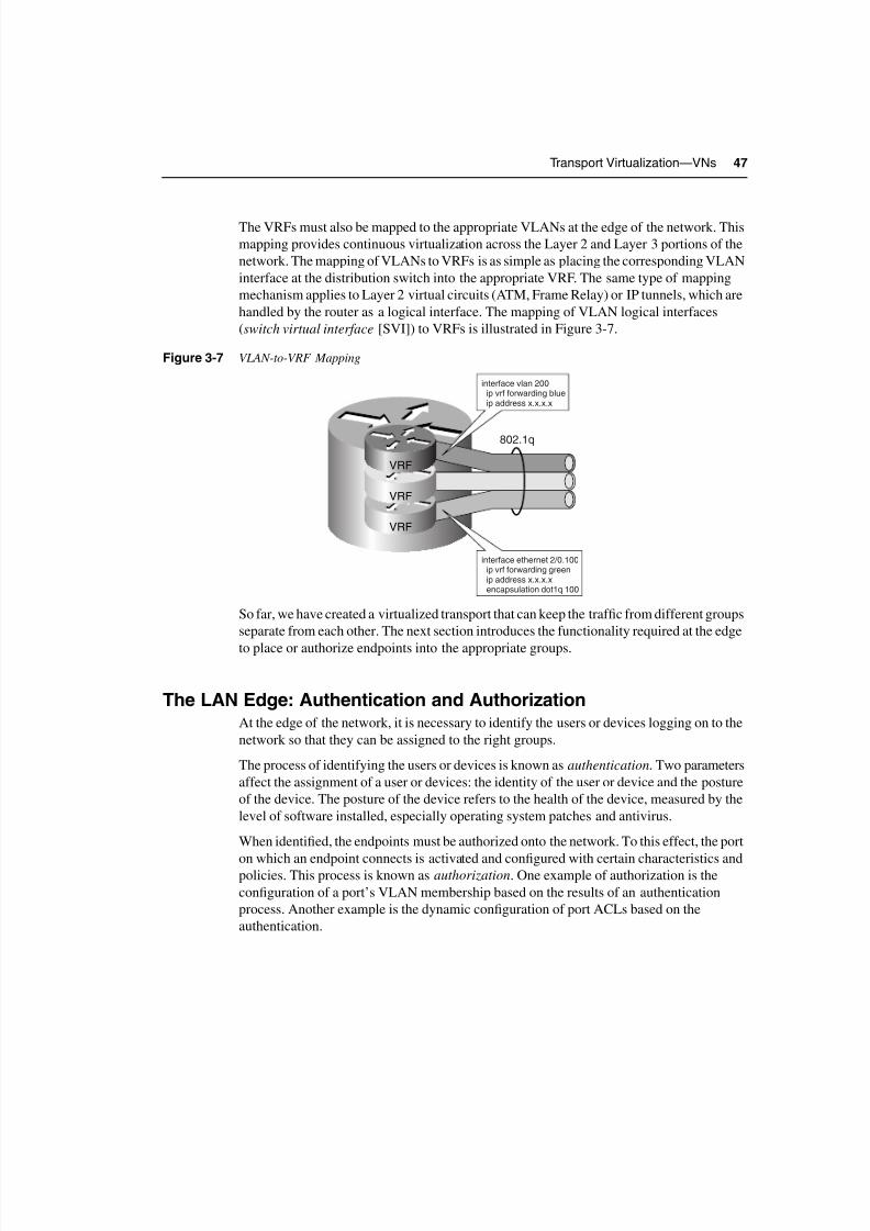
The VRF achieves the virtualization of the networking device at Layer 3. After the devices
have been virtualized, the virtual instances in the different devices must be interconnected
to form a VN. Thus, a VN is a group of interconnected VRFs. In theory, this interconnection
could be achieved by using dedicated physical links for each VN (group of interconnectedVRFs). In practice, this would be inefficient and costly. Hence, it is necessary to virtualize
the data path between the VRFs to provide logical interconnectivity between the VRFs that
participate in a VN. The type of data-path virtualization will vary depending on how far the
VRFs are from each other. If the virtualized devices are directly connected to each other
(single hop), link or circuit virtualization is necessary. If the virtualized devices are
802.1q802.1q
IP Switching IP Switching
SVI orSub-Interface
(Layer 3)
SVI orSub-Interface
(Layer 3)
Each VRF Usesa Dedicated
Routing Instance
VRF
VRF
VRF
8/6/2019 Virtualized Enterprise
http://slidepdf.com/reader/full/virtualized-enterprise 12/19
46 Chapter 3: A Basic Virtualized Enterprise
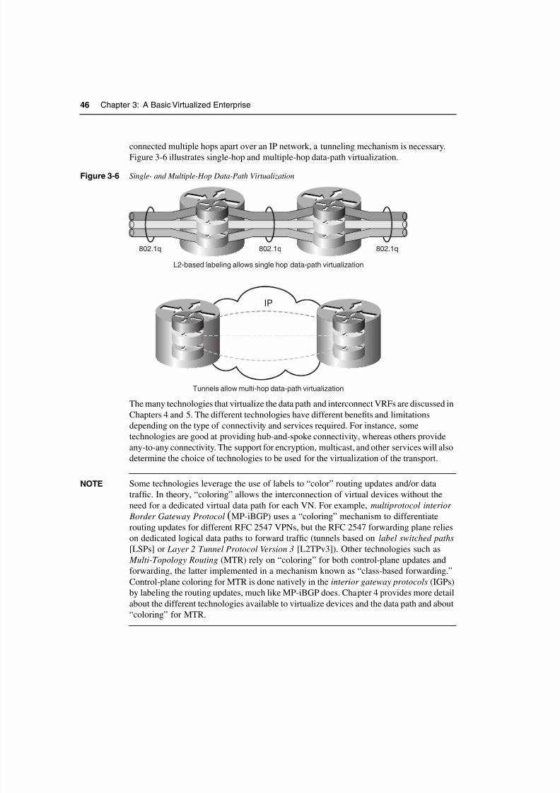
connected multiple hops apart over an IP network, a tunneling mechanism is necessary.
Figure 3-6 illustrates single-hop and multiple-hop data-path virtualization.
Figure 3-6 Single- and Multiple-Hop Data-Path Virtualization
The many technologies that virtualize the data path and interconnect VRFs are discussed in
Chapters 4 and 5. The different technologies have different benefits and limitationsdepending on the type of connectivity and services required. For instance, some
technologies are good at providing hub-and-spoke connectivity, whereas others provide
any-to-any connectivity. The support for encryption, multicast, and other services will also
determine the choice of technologies to be used for the virtualization of the transport.
NOTE Some technologies leverage the use of labels to “color” routing updates and/or data
traffic. In theory, “coloring” allows the interconnection of virtual devices without the
need for a dedicated virtual data path for each VN. For example, multiprotocol interior
Border Gateway Protocol (MP-iBGP) uses a “coloring” mechanism to differentiate
routing updates for different RFC 2547 VPNs, but the RFC 2547 forwarding plane relies
on dedicated logical data paths to forward traffic (tunnels based on label switched paths
[LSPs] or Layer 2 Tunnel Protocol Version 3 [L2TPv3]). Other technologies such as
Multi-Topology Routing (MTR) rely on “coloring” for both control-plane updates and
forwarding, the latter implemented in a mechanism known as “class-based forwarding.”
Control-plane coloring for MTR is done natively in the interior gateway protocols (IGPs)
by labeling the routing updates, much like MP-iBGP does. Chapter 4 provides more detail
about the different technologies available to virtualize devices and the data path and about
“coloring” for MTR.
802.1q802.1q 802.1q
IP
Tunnels allow multi-hop data-path virtualization
L2-based labeling allows single hop data-path virtualization
8/6/2019 Virtualized Enterprise
http://slidepdf.com/reader/full/virtualized-enterprise 13/19
8/6/2019 Virtualized Enterprise
http://slidepdf.com/reader/full/virtualized-enterprise 14/19
8/6/2019 Virtualized Enterprise
http://slidepdf.com/reader/full/virtualized-enterprise 15/19
Central Services Access: Virtual Network Perimeter 49
Central Services Access: Virtual Network PerimeterThe default state of a VN is to be totally isolated from other VNs. In this respect, VNs could
be seen as physically separate networks. However, because VNs actually belong to a
common physical network, it is desirable for these VNs to share certain services such as
Internet access, management stations, DHCP services, Domain Name System (DNS)
services, or server farms. These services will usually be located outside of the different VNs
or in a VN of their own. So, it is necessary for these VNs to have a gateway to connect to
the “outside world.” The outside world is basically any network outside the VN such as the
Internet or other VNs. Because this is the perimeter of the VN, it is also desirable for this
perimeter to be protected by security devices such as firewalls and intrusion detection
systems (IDSs). Typically, the perimeter is deployed at a common physical location for
most VNs. Hence, this location is known as the central services site, and the securitydevices here deployed can be shared by many VNs.
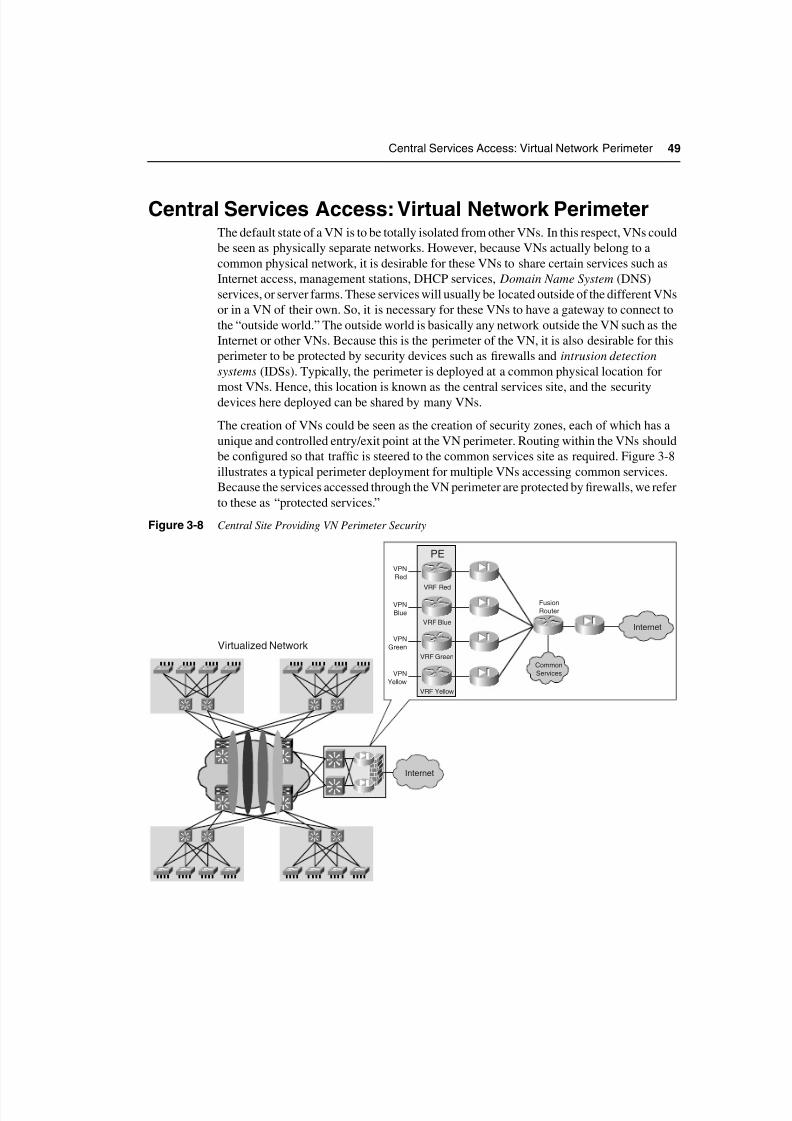
The creation of VNs could be seen as the creation of security zones, each of which has a
unique and controlled entry/exit point at the VN perimeter. Routing within the VNs should
be configured so that traffic is steered to the common services site as required. Figure 3-8
illustrates a typical perimeter deployment for multiple VNs accessing common services.
Because the services accessed through the VN perimeter are protected by firewalls, we refer
to these as “protected services.”
Figure 3-8 Central Site Providing VN Perimeter Security
Internet
Internet
Common
Services
VPN
Red
VPN
Blue
VPN
Green
VPN
Yellow
VRF Green
VRF Yellow
VRF Blue
VRF Red
PE
Virtualized Network
Fusion
Router
8/6/2019 Virtualized Enterprise
http://slidepdf.com/reader/full/virtualized-enterprise 16/19
8/6/2019 Virtualized Enterprise
http://slidepdf.com/reader/full/virtualized-enterprise 17/19
Central Services Access: Virtual Network Perimeter 51
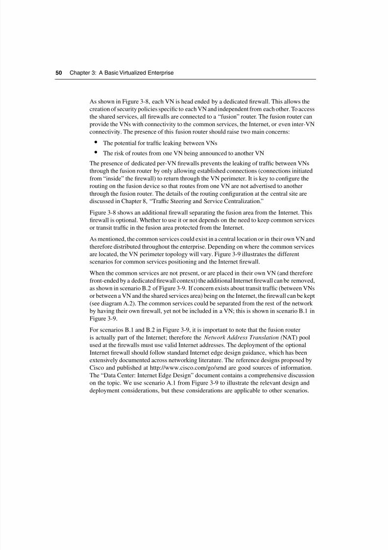
Figure 3-9 Common Services Positioning
Unprotected ServicesIn contrast with circuit-based technologies such as ATM or Frame Relay, most Layer 3 VPN
technologies allow enough flexibility for traffic to be leaked between VNs in a controlled
manner by importing and exporting routes between VNs to provide IP connectivity between
the VNs. Thus, the exchange of traffic between the VNs may happen within the IP core and
not have to pass through the VN perimeter firewalls at the central site. This type of inter-
VN connectivity can be used to provide services, such as DHCP or DNS, that do not need
to be protected by the central site firewall, or that would represent an unnecessary burden
to the VN perimeter firewalls. Because of the any-to-any nature of an IP cloud, there is little
Internet
IP Services
Services VPN
Orange
Yellow
Green
Blue
Red
Fusion
NATNATA.1
Internet
IP ServicesOrange
Yellow
Green
Blue
Red
Fusion
NATB.1
Internet
Fusion
NATA.2
Internet
Fusion
B.2
Orange
Yellow
Green
Blue
Red
NAT
Services VPN
Orange
Yellow
Green
Blue
Red
NAT
8/6/2019 Virtualized Enterprise
http://slidepdf.com/reader/full/virtualized-enterprise 18/19
8/6/2019 Virtualized Enterprise
http://slidepdf.com/reader/full/virtualized-enterprise 19/19
Summary 53
It is also important to remember that when virtualizing a network, not everything must be
migrated onto the VNs created. VN technologies are overlaid onto the existing operational
network infrastructure. Therefore, the network continues to function as it did before the
virtualization, but now has VNs overlaid on top of it. The endpoints using the network could
belong to the original network or to a VN. This provides a clear path to a phased migration
and support for groups that do not require a dedicated VN.