virtuoso® schematic composer tutorial
TRANSCRIPT

Virtuoso® Schematic Composer Tutorial
Product Version 5.0June 2003

1991-2003 Cadence Design Systems, Inc. All rights reserved.Printed in the United States of America.
Cadence Design Systems, Inc., 555 River Oaks Parkway, San Jose, CA 95134, USA
Trademarks: Trademarks and service marks of Cadence Design Systems, Inc. (Cadence) contained inthis document are attributed to Cadence with the appropriate symbol. For queries regarding Cadence’strademarks, contact the corporate legal department at the address shown above or call 1-800-862-4522.
All other trademarks are the property of their respective holders.
Restricted Print Permission: This publication is protected by copyright and any unauthorized use of thispublication may violate copyright, trademark, and other laws. Except as specified in this permissionstatement, this publication may not be copied, reproduced, modified, published, uploaded, posted,transmitted, or distributed in any way, without prior written permission from Cadence. This statement grantsyou permission to print one (1) hard copy of this publication subject to the following conditions:
1. The publication may be used solely for personal, informational, and noncommercial purposes;2. The publication may not be modified in any way;3. Any copy of the publication or portion thereof must include all original copyright, trademark, and other
proprietary notices and this permission statement; and4. Cadence reserves the right to revoke this authorization at any time, and any such use shall be
discontinued immediately upon written notice from Cadence.
Disclaimer: Information in this publication is subject to change without notice and does not represent acommitment on the part of Cadence. The information contained herein is the proprietary and confidentialinformation of Cadence or its licensors, and is supplied subject to, and may be used only by Cadence’scustomer in accordance with, a written agreement between Cadence and its customer. Except as may beexplicitly set forth in such agreement, Cadence does not make, and expressly disclaims, anyrepresentations or warranties as to the completeness, accuracy or usefulness of the information containedin this document. Cadence does not warrant that use of such information will not infringe any third partyrights, nor does Cadence assume any liability for damages or costs of any kind that may result from use ofsuch information.
Restricted Rights: Use, duplication, or disclosure by the Government is subject to restrictions as set forthin FAR52.227-14 and DFAR252.227-7013 et seq. or its successor.

Virtuoso Schematic Composer Tutorial
Contents
Preface . . . . . . . . . . . . . . . . . . . . . . . . . . . . . . . . . . . . . . . . . . . . . . . . . . . . . . . . . . . . . . 7
Related Documents . . . . . . . . . . . . . . . . . . . . . . . . . . . . . . . . . . . . . . . . . . . . . . . . . . . . . . 8Typographic and Syntax Conventions . . . . . . . . . . . . . . . . . . . . . . . . . . . . . . . . . . . . . . . . 8
1Installing the Tutorial Database . . . . . . . . . . . . . . . . . . . . . . . . . . . . . . . . . 11
Prerequisites . . . . . . . . . . . . . . . . . . . . . . . . . . . . . . . . . . . . . . . . . . . . . . . . . . . . . . . . . . 11Overview of the Installation Process . . . . . . . . . . . . . . . . . . . . . . . . . . . . . . . . . . . . . . . . 11Your Working Environment . . . . . . . . . . . . . . . . . . . . . . . . . . . . . . . . . . . . . . . . . . . . . . . 12Copying the Installation Script . . . . . . . . . . . . . . . . . . . . . . . . . . . . . . . . . . . . . . . . . . . . . 12Running the Installation Script . . . . . . . . . . . . . . . . . . . . . . . . . . . . . . . . . . . . . . . . . . . . . 13Copying and Editing the Dot Files . . . . . . . . . . . . . . . . . . . . . . . . . . . . . . . . . . . . . . . . . . 14
Copying the System-Specific Dot Files . . . . . . . . . . . . . . . . . . . . . . . . . . . . . . . . . . . 14Editing the .cshrc File . . . . . . . . . . . . . . . . . . . . . . . . . . . . . . . . . . . . . . . . . . . . . . . . . 14Copying the Environment Dot File . . . . . . . . . . . . . . . . . . . . . . . . . . . . . . . . . . . . . . . 16
Starting the Schematic Composer Software . . . . . . . . . . . . . . . . . . . . . . . . . . . . . . . . . . 16Setting the Paths to the Libraries . . . . . . . . . . . . . . . . . . . . . . . . . . . . . . . . . . . . . . . . . . . 18
2Getting Started with Schematic Composer. . . . . . . . . . . . . . . . . . . . 21
About the Tutorial Libraries, Cells, and Cellviews . . . . . . . . . . . . . . . . . . . . . . . . . . . . . . 21Setting Options . . . . . . . . . . . . . . . . . . . . . . . . . . . . . . . . . . . . . . . . . . . . . . . . . . . . . . . . 23Opening the Schematic Window . . . . . . . . . . . . . . . . . . . . . . . . . . . . . . . . . . . . . . . . . . . 24Viewing the Schematic . . . . . . . . . . . . . . . . . . . . . . . . . . . . . . . . . . . . . . . . . . . . . . . . . . . 26Browsing the Schematic Hierarchy . . . . . . . . . . . . . . . . . . . . . . . . . . . . . . . . . . . . . . . . . 28
Moving Down the Schematic Hierarchy . . . . . . . . . . . . . . . . . . . . . . . . . . . . . . . . . . . 29Moving Up the Schematic Hierarchy . . . . . . . . . . . . . . . . . . . . . . . . . . . . . . . . . . . . . 30
Closing the Design and Quitting the Software . . . . . . . . . . . . . . . . . . . . . . . . . . . . . . . . . 31
June 2003 3 Product Version 5.0

Virtuoso Schematic Composer Tutorial
3Creating Symbols and Pins. . . . . . . . . . . . . . . . . . . . . . . . . . . . . . . . . . . . . . 33
Creating a New Design . . . . . . . . . . . . . . . . . . . . . . . . . . . . . . . . . . . . . . . . . . . . . . . . . . 34Opening the top_level Design . . . . . . . . . . . . . . . . . . . . . . . . . . . . . . . . . . . . . . . . . . . . . 34Placing the ALU Symbol . . . . . . . . . . . . . . . . . . . . . . . . . . . . . . . . . . . . . . . . . . . . . . . . . 35Creating the One’s Complement Symbol . . . . . . . . . . . . . . . . . . . . . . . . . . . . . . . . . . . . . 37Creating the Accumulator Symbol . . . . . . . . . . . . . . . . . . . . . . . . . . . . . . . . . . . . . . . . . . 40Placing the Accumulator Symbol . . . . . . . . . . . . . . . . . . . . . . . . . . . . . . . . . . . . . . . . . . . 41Placing the One’s Complement Symbol . . . . . . . . . . . . . . . . . . . . . . . . . . . . . . . . . . . . . 43Adding the Schematic Input and Output Pins . . . . . . . . . . . . . . . . . . . . . . . . . . . . . . . . . 44Adding the DEC Bus . . . . . . . . . . . . . . . . . . . . . . . . . . . . . . . . . . . . . . . . . . . . . . . . . . . . 47Adding the Output Bus . . . . . . . . . . . . . . . . . . . . . . . . . . . . . . . . . . . . . . . . . . . . . . . . . . . 51
4Adding Wires, Checking the Schematic, and Attaching aBorder . . . . . . . . . . . . . . . . . . . . . . . . . . . . . . . . . . . . . . . . . . . . . . . . . . . . . . . . . . . . . . 53
Wiring the Input Pins . . . . . . . . . . . . . . . . . . . . . . . . . . . . . . . . . . . . . . . . . . . . . . . . . . . . 53Wiring the ALU . . . . . . . . . . . . . . . . . . . . . . . . . . . . . . . . . . . . . . . . . . . . . . . . . . . . . . . . . 56Naming the Nets . . . . . . . . . . . . . . . . . . . . . . . . . . . . . . . . . . . . . . . . . . . . . . . . . . . . . . . 58Placing the Input Wire Names . . . . . . . . . . . . . . . . . . . . . . . . . . . . . . . . . . . . . . . . . . . . . 60Placing the Output Wire Names . . . . . . . . . . . . . . . . . . . . . . . . . . . . . . . . . . . . . . . . . . . 61Checking the Schematic . . . . . . . . . . . . . . . . . . . . . . . . . . . . . . . . . . . . . . . . . . . . . . . . . 62
Setting Up the Check Rules . . . . . . . . . . . . . . . . . . . . . . . . . . . . . . . . . . . . . . . . . . . . 63Running Check and Save . . . . . . . . . . . . . . . . . . . . . . . . . . . . . . . . . . . . . . . . . . . . . . 64Identifying the Errors . . . . . . . . . . . . . . . . . . . . . . . . . . . . . . . . . . . . . . . . . . . . . . . . . 66
Naming the DEC Bus . . . . . . . . . . . . . . . . . . . . . . . . . . . . . . . . . . . . . . . . . . . . . . . . . . . . 69Creating a Sheet Border and Title . . . . . . . . . . . . . . . . . . . . . . . . . . . . . . . . . . . . . . . . . . 70
Creating a Border . . . . . . . . . . . . . . . . . . . . . . . . . . . . . . . . . . . . . . . . . . . . . . . . . . . . 70Centering the Schematic within the Border . . . . . . . . . . . . . . . . . . . . . . . . . . . . . . . . 71Adding a Name to the Title Block . . . . . . . . . . . . . . . . . . . . . . . . . . . . . . . . . . . . . . . . 73
June 2003 4 Product Version 5.0

Virtuoso Schematic Composer Tutorial
5Creating the Accumulator Schematic . . . . . . . . . . . . . . . . . . . . . . . . . . 77
About the Accumulator . . . . . . . . . . . . . . . . . . . . . . . . . . . . . . . . . . . . . . . . . . . . . . . . . . 77Adding Instances . . . . . . . . . . . . . . . . . . . . . . . . . . . . . . . . . . . . . . . . . . . . . . . . . . . . . . . 78
Adding Two 4-Bit Adder Symbols . . . . . . . . . . . . . . . . . . . . . . . . . . . . . . . . . . . . . . . . 80Adding the 8-Bit Register Symbol . . . . . . . . . . . . . . . . . . . . . . . . . . . . . . . . . . . . . . . 82Adding Power and Ground Symbols . . . . . . . . . . . . . . . . . . . . . . . . . . . . . . . . . . . . . . 83
Adding Wires and Buses . . . . . . . . . . . . . . . . . . . . . . . . . . . . . . . . . . . . . . . . . . . . . . . . . 85Stretching the Register Symbol . . . . . . . . . . . . . . . . . . . . . . . . . . . . . . . . . . . . . . . . . 85Wiring the Adders, Power Supply, and Ground Symbols . . . . . . . . . . . . . . . . . . . . . . 87Moving the Schematic Pins for Space . . . . . . . . . . . . . . . . . . . . . . . . . . . . . . . . . . . . 90Drawing the Buses . . . . . . . . . . . . . . . . . . . . . . . . . . . . . . . . . . . . . . . . . . . . . . . . . . . 91Wiring the CLK Pin . . . . . . . . . . . . . . . . . . . . . . . . . . . . . . . . . . . . . . . . . . . . . . . . . . . 92Wiring the Adders . . . . . . . . . . . . . . . . . . . . . . . . . . . . . . . . . . . . . . . . . . . . . . . . . . . . 93Wiring the Register . . . . . . . . . . . . . . . . . . . . . . . . . . . . . . . . . . . . . . . . . . . . . . . . . . . 96
Naming the Nets . . . . . . . . . . . . . . . . . . . . . . . . . . . . . . . . . . . . . . . . . . . . . . . . . . . . . . . 97Naming the Nets That Tap the B Bus . . . . . . . . . . . . . . . . . . . . . . . . . . . . . . . . . . . . . 97Naming the Nets That Tap the Y Bus . . . . . . . . . . . . . . . . . . . . . . . . . . . . . . . . . . . . 103
Checking the Schematic . . . . . . . . . . . . . . . . . . . . . . . . . . . . . . . . . . . . . . . . . . . . . . . . 103
6Creating the Analog Amplifier Schematic. . . . . . . . . . . . . . . . . . . . . 105
About the Analog Amplifier Schematic . . . . . . . . . . . . . . . . . . . . . . . . . . . . . . . . . . . . . 106Creating the amp Schematic Cellview . . . . . . . . . . . . . . . . . . . . . . . . . . . . . . . . . . . . . . 106
Adding Symbols for the Four Resistors . . . . . . . . . . . . . . . . . . . . . . . . . . . . . . . . . . 107Changing Resistor Parameter Values . . . . . . . . . . . . . . . . . . . . . . . . . . . . . . . . . . . 109Adding a Capacitor and Changing Its Parameter Values . . . . . . . . . . . . . . . . . . . . . 111Adding Symbols for the Power and Ground . . . . . . . . . . . . . . . . . . . . . . . . . . . . . . . 112Adding the Transistor Symbol . . . . . . . . . . . . . . . . . . . . . . . . . . . . . . . . . . . . . . . . . . 113Adding the I/O Pins . . . . . . . . . . . . . . . . . . . . . . . . . . . . . . . . . . . . . . . . . . . . . . . . . 115Aligning the Symbols . . . . . . . . . . . . . . . . . . . . . . . . . . . . . . . . . . . . . . . . . . . . . . . . 116Wiring the Schematic . . . . . . . . . . . . . . . . . . . . . . . . . . . . . . . . . . . . . . . . . . . . . . . . 118Cleaning Up the Schematic . . . . . . . . . . . . . . . . . . . . . . . . . . . . . . . . . . . . . . . . . . . 119Adding CDF Data . . . . . . . . . . . . . . . . . . . . . . . . . . . . . . . . . . . . . . . . . . . . . . . . . . . 121
June 2003 5 Product Version 5.0

Virtuoso Schematic Composer Tutorial
Creating a Symbol from a Schematic . . . . . . . . . . . . . . . . . . . . . . . . . . . . . . . . . . . . . . 125
7Preparing the top_level Schematic for Simulation . . . . . . . . . . . 129
Adding the ones_comp Circuit . . . . . . . . . . . . . . . . . . . . . . . . . . . . . . . . . . . . . . . . . . . . 129Finishing the top_level Schematic . . . . . . . . . . . . . . . . . . . . . . . . . . . . . . . . . . . . . . . . . 130
ASolving Problems . . . . . . . . . . . . . . . . . . . . . . . . . . . . . . . . . . . . . . . . . . . . . . . . 133
June 2003 6 Product Version 5.0

Virtuoso Schematic Composer Tutorial
Preface
The Virtuoso® schematic composer is a design entry tool that supports the work of logic andcircuit design engineers. Physical layout designers and printed circuit board designers canuse the information as background material to support their work.
The preface discusses the following:
■ Related Documents on page 8
■ Typographic and Syntax Conventions on page 8
June 2003 7 Product Version 5.0

Virtuoso Schematic Composer TutorialPreface
Related Documents
The schematic composer is often used with other Cadence® products or requires knowledgeof special languages such as the Cadence SKILL language. The following documents giveyou more information about these tools and languages, but in general for this tutorial, you willnot need to refer to them.
■ The Design Framework II User Guide provides information if you are not familiar withCadence terms and starting your system.
■ The Cadence Application Infrastructure User Guide provides additional informationabout the architecture.
■ The Virtuoso Schematic Composer User Guide describes how to create and checkschematics and symbols.
■ The Inherited Connections Flow Guide describes how to use inherited connectionsand net expressions with various Cadence tools in the design flow.
■ The Virtuoso Schematic Composer SKILL Functions Reference is for users whocustomize the standard product.
■ The Library Manager User Guide explains how to open or create cellviews from theLibrary Manager.
■ The Verilog-XL Integration for Schematic Composer Reference and the Verilog-XL Integration for Schematic Composer User Guide describe how to use theschematic composer with Verilog® HDL. The manual is intended for integrated circuitdesigners who are using the Verilog-XL logic simulator to verify the logic of their designs.
■ The Virtuoso VHDL Interface for Schematic Composer User Guide describes howto use the schematic composer with VHDL.
Typographic and Syntax Conventions
This section describes typographic and syntax conventions used in this manual.
text Indicates text you must type exactly as it is presented.
z_argument Indicates text that you must replace with an appropriateargument. The prefix (in this case, z_) indicates the data typethe argument can accept. Do not type the data type orunderscore.
June 2003 8 Product Version 5.0

Virtuoso Schematic Composer TutorialPreface
[ ] Denotes optional arguments. When used with vertical bars, theyenclose a list of choices from which you can choose one.
{ } Used with vertical bars and encloses a list of choices from whichyou must choose one.
| Separates a choice of options.
… Indicates that you can repeat the previous argument.
=> Precedes the values returned by a Cadence® SKILL languagefunction.
/ Separates the possible values that can be returned by aCadence SKILL language function.
text Indicates names of manuals, menu commands, form buttons,and form fields.
Important
The language requires many characters not included in the preceding list. You musttype these characters exactly as they are shown in the syntax.
June 2003 9 Product Version 5.0

Virtuoso Schematic Composer TutorialPreface
June 2003 10 Product Version 5.0

Virtuoso Schematic Composer Tutorial
1Installing the Tutorial Database
If you are using an installed tutorial that other people have used, you need to reset the files.See “Running the Installation Script” on page 13.
Prerequisites
Before you can install the tutorial database, either the Virtuoso® schematic composersoftware must be installed on your system or your account must have a path to the schematiccomposer software hierarchy.
You can use the tutorial if you have one of the following environments:
■ Open Windows with OPENLOOK Window Manager
■ X11 Windows with Motif Window Manager
■ Open Windows with Motif Window Manager
■ X11 Windows with OPENLOOK Window Manager
Overview of the Installation Process
Installing the tutorial database consists of these procedures:
1. Copying the installation script from the tutorial database in the schematic composersoftware hierarchy to your machine
2. Running the installation script
3. Copying and editing the dot files required to set up your tutorial account
4. Starting the schematic composer software
5. Setting the library paths to the eight tutorial libraries
June 2003 11 Product Version 5.0

Virtuoso Schematic Composer TutorialInstalling the Tutorial Database
Your Working Environment
At this moment, you are using the environment files in your home directory.
■ You are set up to use the Cadence schematic composer software designated in your.cshrc file in your home directory.
■ The tutorial consists of its own set of environment files. You copy them into a separatedirectory so that they will not interfere with the environment files in your home directory.
■ You need to set the Cadence schematic composer software in the tutorial environmentfile, .cshrc, to the same path noted in your home directory .cshrc file. This procedureis described in the next sections.
Copying the Installation Script
The tutorial installation script copies the data files required to run the tutorial. The tutorialinstallation software assumes that you have access to a standard set of Cadence® software.
1. To find the path (referred to as your_install_dir) where the source data is located,type the following:
which executableName
For example, which icds
The executable name you enter depends on which software package your companypurchased. The different executables used to start the schematic composer softwarerefer to the expandable sets of Cadence design tools:
❑ icde includes the schematic editor, symbol editor, and plotting
❑ icds includes all of the above, plus digital simulator interfaces
❑ icms includes all of the above plus mixed signal functionality
❑ msfb includes mixed signal front-to-back functionality
❑ icfb includes full-chip design functionality
2. Create a working directory to use as the target directory on your machine calledcomptut.
mkdir comptut
3. Copy the installation script restart to your comptut directory:
cp -r your_install_dir/tools/dfII/samples/tutorials/composer/restart ~/comptut/.
June 2003 12 Product Version 5.0

Virtuoso Schematic Composer TutorialInstalling the Tutorial Database
Running the Installation Script
To copy the tutorial files into the tutorial account or to reset the files that someone else hasalready used, do the following:
1. Exit the Cadence software if it is running.
2. Run the restart script from the composer directory.
The installation script displays a welcome message.
3. Press Return to continue the installation.
4. Choose one of the following:
❑ If you are installing the tutorial for the first time, type 1 and press Return.
❑ If you are using an installed tutorial that other people have used, type 2 and pressReturn to remove old user designs and reset the tutorial. Certain files will not becopied over.
5. Press Y to reply to the prompt about copying files from the Cadence hierarchy.
You are now prompted to type the source directory.
6. Type the source directory to the schematic composer tutorial files:
your_install_dir/tools/dfII/samples/tutorials/composer
7. Press Return.
8. Type in the target directory:
~/comptut
9. Press Return.
The restart script copies the tutorial directory to ~/comptut by default so that it willnot overwrite any files in your home directory.
The following is a list of the files and directories in the tutorial directory:
drwxr-xr-x 7 integ 1024 Jun 25 13:46 .drwx------ 31 integ 3072 Jun 25 13:45 ..-rw-r--r-- 1 integ 78 Jun 20 16:56 .X11-rw-r--r-- 1 integ 16048 Jun 20 16:56 .Xdefaults-rwxr-xr-x 1 integ 6472 Jun 21 10:47 .cdsinit-rw-r--r-- 1 integ 1217 Jun 21 10:48 .cshrc-rw-r--r-- 1 integ 29 Jun 20 16:56 .datestamp-rw-r--r-- 1 integ 1570 Jun 20 16:56 .login-rw-r--r-- 1 integ 2303 Jun 20 16:56 .mwmrc-rwxr-xr-x 1 integ 339 Jun 20 16:56 .openwin-init-rw-r--r-- 1 integ 1529 Jun 20 16:56 .openwin-menu-rwxr-xr-x 1 integ 441 Jun 20 16:56 .xinitrc
June 2003 13 Product Version 5.0

Virtuoso Schematic Composer TutorialInstalling the Tutorial Database
-rwxr-xr-x 1 integ 441 Jun 20 16:56 .xinitrcmwm-rwxr-xr-x 1 integ 446 Jun 20 16:56 .xinitrcolwmdrwxrwxr-x 5 integ 512 Jun 21 10:46 TTL_tutor/-rw-r--r-- 1 integ 514 Jun 21 11:13 cds.libdrwxr-xr-x 6 integ 512 Jun 18 12:44 dotfiles/drwxrwxr-x 5 integ 512 Jun 21 10:46 master/-rwxr-xr-x 1 integ 7981 Jun 21 10:46 restart-rw-r--r-- 1 integ 720 Jun 21 11:12 template.bomdrwxrwxr-x 2 integ 512 Jun 21 10:46 tutorial/-rw-r--r-- 1 integ 481 Jun 21 11:11 tutorial.mechdrwxrwxr-x 3 integ 512 Jun 21 10:46 user_ASIC/
Copying and Editing the Dot Files
The dotfiles directory is part of the tutorial database copied by restart.
Copying the System-Specific Dot Files
The dotfiles directory contains four subdirectories:
■ dec
■ hp
■ ibm
■ sun
Each subdirectory contains system-specific setup and window management files for astandard UNIX environment.
To copy dot files for your environment from the Cadence-supplied tutorial directory to thedirectory you set up on your machine, do the following:
➤ Type
cp -r your_install_dir/tools/dfII/samples/tutorials/composer/dotfiles/subdirectory/.* ~/comptut/dotfiles/.
where subdirectory is dec, hp, ibm, or sun.
Editing the .cshrc File
To set up the .cshrc file so that you can start the Composer Tutorial, do the following:
1. To match your environment, edit the environment path:
set Xpath=(/usr/openwin/demo /usr/openwin/bin/xview /usr/bin/X11 /usr/openwin/bin)
June 2003 14 Product Version 5.0

Virtuoso Schematic Composer TutorialInstalling the Tutorial Database
2. To set the correct Cadence software installation path, add the line:
setenv your_install_dir = hostname
For example,
setenv CDS_INST_DIR = /net/cds11617/cds/4.4.6/red
Note: In all the examples in this section, the path variable your_install_dirshould be the same; for example, CDS_INST_DIR.
3. To set the correct FrameMaker path, edit the line
setenv FMHOME /usr/frameset Framepath=( /usr/frame/bin )
For example,
setenv FMHOME /usr/frameset Framepath=( $FMHOME/bin )
4. To set the location of the Cadence hierarchy, edit the line
set cdsPath=( /cds/bin )
For example:
set cdsPath=( $your_install_dir/bin $your_install_dir/tools/bin$your_install_dir/tools/dfII/bin $your_install_dir/tools/dfII/pvt/bin)
5. Comment out or delete any setenv commands you are not using, or edit them.
To comment out a line, use the pound ( # ) key.
endif#---- XNEWS environssetenv OPENWINHOME /usr/openwinsetenv FONTPATH $OPENWINHOME/lib/fonts:/usr/asi/system/owsfontssetenv FRAMEBUFFER /dev/cgthree0setenv LD_LIBRARY_PATH /usr/lib:/usr/openwin/lib#-------END XNEWS ------
set path = ( $cdsPath $XPath $mypath $Framepath $asiPath /bin /usr/gda )
# prance stuff# Prance Environment Setupsetenv NSEGS 0setenv DEFSIZE 10485760setenv SHMID 14setenv HPGL_QUEUE -Phpglsetenv VTEC_QUEUE -Pvtecsetenv ASI_SHMEM nosetenv LM_LICENSE_FILE /usr/asi/license/pgtd.confsetenv DBPATH /usr/asi/aplibsetenv UNIFY /usr/unify/lib
For example,
endif#---- XNEWS environssetenv OPENWINHOME /usr/openwinsetenv LD_LIBRARY_PATH /usr/lib/X11:$OPENWINHOME/lib:/usr/
June 2003 15 Product Version 5.0

Virtuoso Schematic Composer TutorialInstalling the Tutorial Database
lib:$your_install_dir/tools/lib#-------END XNEWS ------
set path = ( $cdsPath $XPath $mypath $Framepath /bin /usr/gda )
6. If you are not using $asiPath, delete it.
7. Reset the environment by typing these commands:
source .cshrcrehash
When you are finished with the tutorial, you can source the .cshrc file in your home directoryand return to that environment.
Copying the Environment Dot File
You now need to copy the environment dot file, .xinitrc, as follows:
■ If you use Open Windows with OPENLOOK Window Manager, copy the following dot fileto your comptut directory:
cp .xinitrcolwm .xinitrc
■ If you use X11 Windows with Motif Window Manager, copy the following dot file to yourcomptut directory:
cp .xinitrcmwm .xinitrc
■ If you use Open Windows with Motif Window Manager, copy the following dot file to yourcomptut directory:
cp .xinitrcmwm .xinitrc
■ If you use X11 Windows with OPENLOOK Window Manager, copy the following dot fileto your comptut directory:
cp .xinitrcolwm .xinitrc
Starting the Schematic Composer Software
To start the Cadence software, do the following:
1. In a terminal window, type one of these commands:
icde &icds &icms &msfb &icfb &
The command you enter depends on which software package your company purchased.
June 2003 16 Product Version 5.0

Virtuoso Schematic Composer TutorialInstalling the Tutorial Database
In this tutorial, all examples are illustrated with the icds display. The ampersand (&) putsthe command in the background so you can continue to use the xterm window for othercommands.
The software is loaded when the following message appears at the end of the loadingscript in the Command Interpreter Window (CIW):
END OF USER CUSTOMIZATION.
The CIW is the main control window for the schematic composer software. If the softwaredoes not load or if error messages appear in the CIW, you must check the tutorialenvironment.
Areas to check include the following:
❑ The paths set in the .cshrc file
❑ The dot files, if you are using your own dot files
❑ The read/write permissions on the tutorial directory
Look for the message END OF USER CUSTOMIZATIONin the CIW.
June 2003 17 Product Version 5.0

Virtuoso Schematic Composer TutorialInstalling the Tutorial Database
Setting the Paths to the Libraries
To set the paths for the eight tutorial libraries, do the following:
1. From the CIW, choose Tools – Library Path Editor.
The Library Path Editor form appears:
2. Edit the default paths of the eight tutorial libraries in the Library Path Editor form asfollows:
basic /your_install_dir/tools/dfII/etc/cdslib/basic
US_8ths /your_install_dir/tools/dfII/etc/cdslib/sheets/US_8ths
analogLib /your_install_dir/tools/dfII/etc/cdslib/artist/analogLib
sample /your_install_dir/tools/dfII/samples/cdslib/sample
TTL_tutor /your_home_dir/comptut/TTL_tutor
master /your_home_dir/comptut/master
tutorial /your_home_dir/comptut/tutorial
user_ASIC /your_home_dir/comptut/user_ASIC
If the path is in red on the Library Path Editor form, the path is incorrect. To findyour_install_dir, type the following:
June 2003 18 Product Version 5.0

Virtuoso Schematic Composer TutorialInstalling the Tutorial Database
which executableName
For example, which icds
3. From the Library Path Editor form, choose File – Save.
June 2003 19 Product Version 5.0

Virtuoso Schematic Composer TutorialInstalling the Tutorial Database
June 2003 20 Product Version 5.0

Virtuoso Schematic Composer Tutorial
2Getting Started with SchematicComposer
If the tutorial is already installed, but someone has used the tutorial before you, run therestart script as described in Running the Installation Script on page 13, choosing theappropriate option to reset the tutorial.
In this chapter, you will learn how to
■ Move and resize the windows on your screen
■ Set up the schematic composer software environment
■ View and zoom in on the top-level schematic
■ Browse a schematic hierarchy
■ Close the schematics you viewed
■ Exit the schematic composer software
About the Tutorial Libraries, Cells, and Cellviews
The tutorial libraries are described as follows:
TTL_tutor Reference library supplied with this tutorial. Contains the standard TTLparts used in the tutorial design.
US_8ths Reference library supplied with the Virtuoso® schematic composersoftware. Contains templates for page borders for schematics.
basic Reference library supplied with the Virtuoso schematic composersoftware. Contains basic symbols, including ground and power.
master Read-only design library. Contains copies of the designs used in thistutorial.
June 2003 21 Product Version 5.0

Virtuoso Schematic Composer TutorialGetting Started with Schematic Composer
Cadence uses the term library to mean both reference libraries, which contain definedcomponents for a specific technology, and design libraries, in which you create your owndesigns.
In the schematic composer software, the designs are called cells. The master librarycontains three cells:
■ The accum cell contains the accumulator used in the top_level schematic.
■ The ones_comp cell contains the one’s complement used in the top_level schematic.
■ The top_level schematic contains the tutorial design, which is a simple processor.
Depending on its use, a cell can have multiple representations or views, such as a symbolor a schematic. For example, the accum cell appears as a symbol in the top_levelschematic, and it also has its own schematic. The accum symbol representation is called acellview.
The top_level cell has one cellview, the schematic view of the top_level schematic.
sample Reference library supplied with the schematic composer software.Contains a sample collection of gates and other electronic circuitry.
tutorial Design library in which you create your schematic.
user_ASIC Reference library supplied with this tutorial. Contains the ArithmeticLogic Unit (ALU) used in the tutorial design.
analogLib Reference library supplied with the schematic composer software.Contains the analog parts used in the analog design.
schematictop_levelmaster
cellslibrary cellviews
accum
ones_comp
schematicsymbol
schematicsymbol
June 2003 22 Product Version 5.0

Virtuoso Schematic Composer TutorialGetting Started with Schematic Composer
Setting Options
To set up options, do the following:
1. From the Command Interpreter Window (CIW), choose Options – User Preferences.
The User Preferences form appears.
2. On the User Preferences form, do the following:
❑ Turn on the Scroll Bars button.
June 2003 23 Product Version 5.0

Virtuoso Schematic Composer TutorialGetting Started with Schematic Composer
The Scroll Bars button displays scroll bars on the schematic windows.
❑ Turn on the Infix button.
Turning on Infix limits the number of mouse clicks required to execute certaincommands, as you will learn later in this chapter.
❑ Click on the Undo Limit slider control and move it right until it reads 10.
The undo limit defines the number of previous commands that can be undone withthe Undo command.
For OA Only: the Undo Limit option is a drop-down box with two values, 0 and 128.
3. Click OK.
The options you set affect the schematics that you display. The options stay in effect untilyou exit the schematic composer software.
Opening the Schematic Window
To open a schematic window, do the following:
1. From the CIW, choose File – Open.
June 2003 24 Product Version 5.0

Virtuoso Schematic Composer TutorialGetting Started with Schematic Composer
The Open File form appears and lets you find and open any cellview of any cell that youhave access to.
2. In the Library Name cyclic field, choose master.
The Open File form changes to display the contents of the master library.
3. In the Cell Names list box, click on top_level.
4. In the View Name cyclic field, choose schematic.
5. Set Mode to read.
You must choose read because the master library is a read-only library.
6. Click OK.
June 2003 25 Product Version 5.0

Virtuoso Schematic Composer TutorialGetting Started with Schematic Composer
The Open File form closes. The top_level schematic appears.
In the next section you will view the detail closer.
Viewing the Schematic
To inspect the design closer so that you can read pin names and wire names, do the following:
➤ From the schematic window, choose Window – Zoom – Zoom In By 2.
one’s complement accumulator ALU
June 2003 26 Product Version 5.0

Virtuoso Schematic Composer TutorialGetting Started with Schematic Composer
The first instance is named ones_comp.
The second instance is named accum, and it has an output bus DEC<0:7>.
June 2003 27 Product Version 5.0

Virtuoso Schematic Composer TutorialGetting Started with Schematic Composer
The third instance is named ALU_ASIC, and it has an output bus OUT<0:3>.
Browsing the Schematic Hierarchy
The top_level cellview is the top schematic in this particular hierarchy. In this section, youdescend one level to view another schematic in the hierarchy.
June 2003 28 Product Version 5.0

Virtuoso Schematic Composer TutorialGetting Started with Schematic Composer
Moving Down the Schematic Hierarchy
To descend the hierarchy to view the accumulator cell, do the following:
1. Choose Design – Hierarchy – Descend Read.
The prompt at the bottom of the window is
Point at instance to descend into.
2. Click on the accumulator.
The accumulator is selected when a box appears around it. The Descend form appears.
3. In the View Name cyclic field, choose schematic.
4. Click OK.
June 2003 29 Product Version 5.0

Virtuoso Schematic Composer TutorialGetting Started with Schematic Composer
The schematic for the accumulator appears.
The accumulator contains
❑ Two 4-bit adders (both 74S283), one below the other. The lower adder is placedupsidedown.
❑ One 8-bit register (74S373)
❑ Nets or wires represented by thin lines
❑ Buses represented by the thick lines
Moving Up the Schematic Hierarchy
To return to the top-level schematic, do the following:
1. Choose Design – Hierarchy – Return To Top.
The top_level schematic reappears.
June 2003 30 Product Version 5.0

Virtuoso Schematic Composer TutorialGetting Started with Schematic Composer
2. Choose Window – Fit.
The Fit command fits the top_level schematic to the window, displaying the entireschematic.
Closing the Design and Quitting the Software
You may want to continue with the tutorial, in which case, go to the next chapter. Each timeyou close the schematic composer software and quit the Cadence® software (using the CIW),the user preferences are reset to the default values. You must open the User Preferencesform and restore the settings as discussed earlier in this chapter.
To close the design, do the following:
➤ Choose Window – Close.
To quit or edit the software, do the following:
➤ Choose File – Exit.
June 2003 31 Product Version 5.0

Virtuoso Schematic Composer TutorialGetting Started with Schematic Composer
June 2003 32 Product Version 5.0

Virtuoso Schematic Composer Tutorial
3Creating Symbols and Pins
You will now create your own top_level schematic. It contains the following:
■ A one’s complement module based on standard functions
■ An accumulator based on standard functions
■ An ALU
■ Two buses, indicated by the thick lines, and nets
If another user has already performed any part of the tutorial in your run directory, you mustreset the tutorial design as described in Chapter 1, “Installing the Tutorial Database.”
In this chapter, you will learn how to
■ Open a new design cell and schematic cellview in your design library
accumulator ALUDEC bus output busone’s complement module
June 2003 33 Product Version 5.0

Virtuoso Schematic Composer TutorialCreating Symbols and Pins
■ Create symbols for two of the three main blocks in the tutorial design
The symbol for the third block, the ALU, is supplied with the tutorial.
■ Place the symbols for the main blocks on the schematic
■ Add the primary input and output pins
■ Add the buses
Creating a New Design
The first step in creating a schematic is to open a new design cell with a schematic cellview.In the Virtuoso® schematic composer software, cell means the overall design and cellviewmeans the representation of the design, such as the schematic or symbol representation.
1. From the Command Interpreter Window (CIW), choose Options – User Preferences.
The User Preferences form appears.
2. On the User Preferences form, do the following:
❑ Turn on the Scroll Bars button.
❑ Turn on the Infix button.
All the procedures in this tutorial assume that you have turned on Infix.
❑ Move the Undo Limit slider control to 10.
For OA Only: the Undo Limit option is a drop-down box with two values, 0 and 128.
3. Click OK.
Opening the top_level Design
In this section, you create the new design cell and schematic cellview by opening a newdesign in the tutorial design library. The tutorial library already exists as part of the tutorialdatabase.
1. From the CIW, choose File – New – Cellview.
June 2003 34 Product Version 5.0

Virtuoso Schematic Composer TutorialCreating Symbols and Pins
The Create New File form appears.
2. On the form, do the following:
❑ In the Library Name cyclic field, choose tutorial.
❑ In the Cell Name field, type top_level.
❑ In the View Name field, type schematic.
❑ In the Tool cyclic field, choose Composer-Schematic.
3. Click OK.
A blank schematic window appears, ready for you to begin entering your design.
Placing the ALU Symbol
In this section, you place the symbol for the ALU in the schematic. The ALU symbol issupplied with the tutorial database.
1. From the schematic composer window, choose Add – Instance.
June 2003 35 Product Version 5.0

Virtuoso Schematic Composer TutorialCreating Symbols and Pins
The Add Instance form appears.
2. On the form, do the following:
❑ In the Library field, type user_ASIC.
❑ In the Cell field, type ALU_ASIC.
❑ In the View field, type symbol.
You can also use the Browse button to assist you in entering the instance name.
3. Move the pointer into the schematic window.
June 2003 36 Product Version 5.0

Virtuoso Schematic Composer TutorialCreating Symbols and Pins
The ALU instance appears in the schematic window attached to the pointer.
4. Position the ALU instance on the right side of the design and click to place it.
5. Move the pointer.
Notice that the ALU instance continues to follow the pointer. This lets you continue toplace copies of the same instance without having to start the command again.
6. Cancel the Add – Instance command by placing the pointer in the schematic windowand pressing Esc.
7. Choose Design – Save to save your work.
Note: When you first place the ALU instance, it might be so large that it barely fits into theschematic window. To give yourself more room on the schematic, zoom out by choosingWindow – Zoom Out By 2.
Creating the One’s Complement Symbol
You can create the one’s complement symbol automatically, based on the symbol’s primaryinput and output pins.
1. In the schematic window, choose Design – Create Cellview – From Pin List.
accumulator ALUDEC bus output busone’s complement module
June 2003 37 Product Version 5.0
Virtuoso Schematic Composer TutorialCreating Symbols and Pins
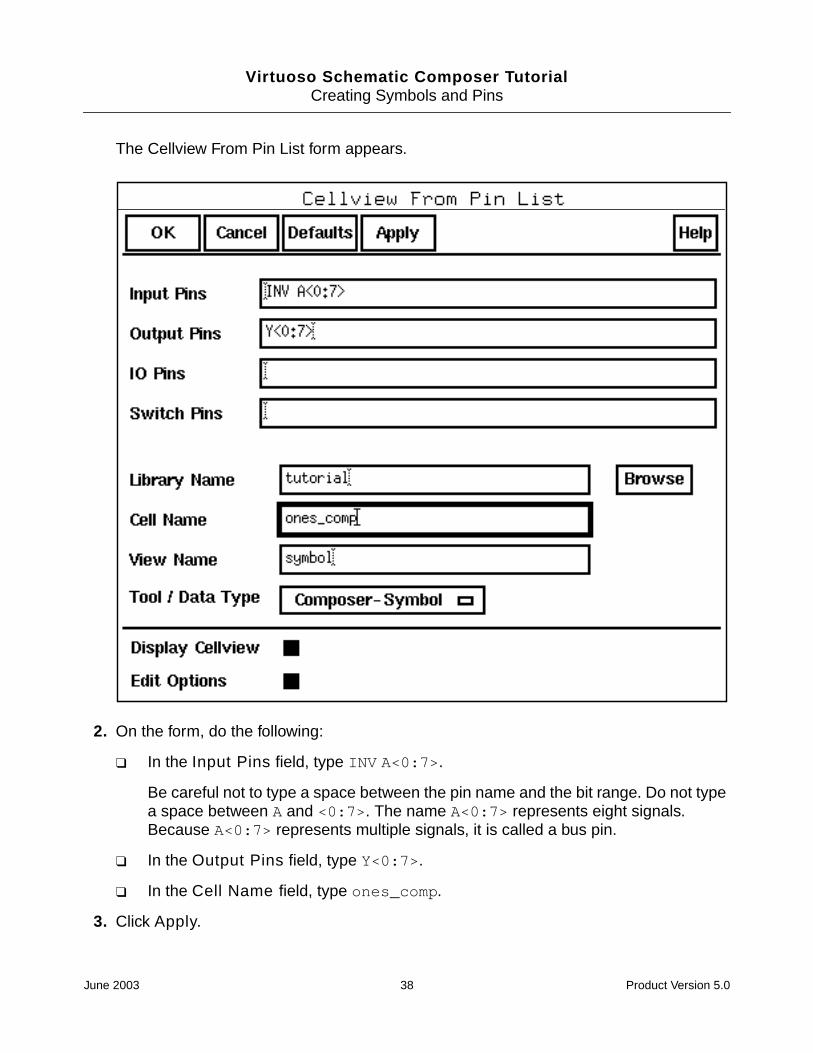
The Cellview From Pin List form appears.
2. On the form, do the following:
❑ In the Input Pins field, type INV A<0:7>.
Be careful not to type a space between the pin name and the bit range. Do not typea space between A and <0:7>. The name A<0:7> represents eight signals.Because A<0:7> represents multiple signals, it is called a bus pin.
❑ In the Output Pins field, type Y<0:7>.
❑ In the Cell Name field, type ones_comp.
3. Click Apply.
June 2003 38 Product Version 5.0

Virtuoso Schematic Composer TutorialCreating Symbols and Pins
The Apply button executes the command but does not cancel the form. (The OK buttonexecutes the command and cancels the form.) You want to keep the command activebecause you will be creating the accumulator symbol after you create the one’scomplement symbol.
The Symbol Generation Options form appears on top of the Cellview From Pin List form.This form appears because the Edit Options button on the Cellview From Pin List formis on by default. This form lets you specify graphic information for the symbol. Regardlessof the order in which the pin names are entered into the Cellview From Pin List form, theSymbol Generation Options form presents the pin names in alphabetical order.
4. Click OK on the Symbol Generation Options form.
June 2003 39 Product Version 5.0

Virtuoso Schematic Composer TutorialCreating Symbols and Pins
A symbol editor window opens to show you the generated symbol. In the future, you canuse this window to modify the appearance and characteristics of the symbol.
When you add the symbol to the top-view schematic later in this tutorial, [@partName]changes to accum and [@instanceName] changes to the names of the nextconsecutive instance, I1.
5. Choose Window – Close to close the ones_comp symbol.
Creating the Accumulator Symbol
You can create the accumulator symbol automatically, based on its primary input and outputpins.
1. On the Cellview From Pin List form which was left open from a previous step, do thefollowing:
❑ In the Input Pins field, type CLK B<0:7>.
❑ In the Output Pins field, type Y<0:7>.
❑ In the Cell Name field, type accum.
June 2003 40 Product Version 5.0

Virtuoso Schematic Composer TutorialCreating Symbols and Pins
❑ Turn off Display Cellview and Edit Options.
2. Click OK.
The CIW displays confirmation messages.
Placing the Accumulator Symbol
To place the accumulator symbol, you can use the Library Browser to fill in the form ratherthan typing in the fields yourself.
1. From the schematic window, choose Add – Instance.
The Add Instance form opens.
CLK B<0:7> A<0:7>
June 2003 41 Product Version 5.0

Virtuoso Schematic Composer TutorialCreating Symbols and Pins
2. Click on the Browse button.
The Library Browser opens.
3. In the Library Browser, do the following:
❑ In the Library list box, click tutorial.
❑ In the Cell list box, click accum.
The Add Instance form changes. The system fills in the fields.
The accumulator instance is attached to the pointer.
4. Position the accumulator in the middle of your design and click to place it.
June 2003 42 Product Version 5.0

Virtuoso Schematic Composer TutorialCreating Symbols and Pins
Do not press Esc, which cancels the command. You want to keep the Add – Instanceform on the screen so that you can place the one’s complement symbol also. Thefollowing diagram shows the complete schematic.
Placing the One’s Complement Symbol
1. In the Library Browser, click ones_comp in the Cell list box to change the Add Instanceform.
accumulator ALUDEC bus output busone’s complement module
June 2003 43 Product Version 5.0

Virtuoso Schematic Composer TutorialCreating Symbols and Pins
The shape of the one’s complement instance now follows the pointer.
2. Position the one’s complement to the left of the accumulator and click to place it.
3. Cancel the Add – Instance command by pressing Esc with the pointer on theschematic.
4. Choose Design – Save to save your work.
Adding the Schematic Input and Output Pins
In the schematic composer software, a schematic pin is a primary input, output, or input/output terminal for the schematic.
June 2003 44 Product Version 5.0

Virtuoso Schematic Composer TutorialCreating Symbols and Pins
1. From the schematic window, choose Add – Pin.
The Add Pin form appears.
2. On the form, do the following:
❑ In the Pin Names field, type CLK INV DATA<0:7> OUT<0:3>.
❑ From the Direction cyclic field, choose input.
You will change the direction on the form to output just before you place theOUT<0:3> pin.
❑ From the Usage cyclic field, choose schematic.
The software places these pins one at a time, in order.
3. Position and click to place the CLK pin.
Note that the CLK pin drops off the Pin Names field.
4. Position and click the INV and DATA<0:7> pins.
Before you place the OUT<0:3> pin, you need to change the pin direction to output.
5. From the Direction cyclic field, choose output.
6. Position and click the OUT<0:3> pin.
June 2003 45 Product Version 5.0
Virtuoso Schematic Composer TutorialCreating Symbols and Pins
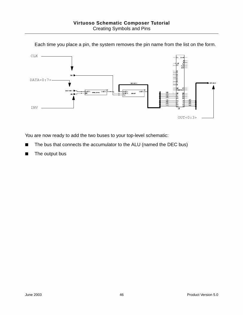
Each time you place a pin, the system removes the pin name from the list on the form.
You are now ready to add the two buses to your top-level schematic:
■ The bus that connects the accumulator to the ALU (named the DEC bus)
■ The output bus
DATA<0:7>
CLK
INV
OUT<0:3>
June 2003 46 Product Version 5.0

Virtuoso Schematic Composer TutorialCreating Symbols and Pins
Adding the DEC Bus
You can draw the buses using a thick line. The width of the line does not affect the connectivityof the buses, but it does help you identify buses on the schematic.
1. Zoom in so that you can see more clearly where to connect the buses.
DEC bus output bus
Then, movethe pointerhere and clickto zoom in.
Move the pointer here andpress z.
June 2003 47 Product Version 5.0

Virtuoso Schematic Composer TutorialCreating Symbols and Pins
2. From the schematic window, choose Add – Wire (wide).
The command line prompts you to start drawing the bus by displaying
Point at starting point for the router or snap to diamond using the "s" key.
3. Click on the accumulator A<0:7> pin to start drawing the DEC bus.
The first portion of the bus ends at the Y pin on the accumulator. If you move the pointeronto the Y pin, you will see that the router places the bus close to the accumulator. In thenext step, you help the router by placing the first segment yourself.
If you place a bus segment incorrectly, press Esc to cancel the command and thenchoose Edit – Undo to undo the error.
4. Move the pointer above the accum instance to position the first segment of the bus andclick to place it.
When you click, the segment appears as a thick line.
Click on theA<0:7> pin tostart drawingthe DEC bus.
Position the firstsegment and click toplace it.
June 2003 48 Product Version 5.0

Virtuoso Schematic Composer TutorialCreating Symbols and Pins
5. Click on the Y pin to complete the first part of the DEC bus.
While routing a wire, notice that the pin closest to the end of the wire becomeshighlighted with a diamond symbol. You can snap-connect the end of the wire to thehighlighted pin by pressing s (for snap). When you press s, the wire jumps to thehighlighted pin, closing the gap with straight segments joined at right angles. Snappingautomatically routes the wire around other symbols. Undo the last step and try routingthe bus again using snapping.
In the next steps, you change the Draw Mode to “X-first,” which is appropriate fordrawing the remaining buses.
6. Choose Add – Wire (wide) again.
7. Before you select anything in the schematic window, press the F3 function key.
The Add Wire form appears. This form lets you change the manner in which wires aredrawn.
Click here to complete the firstpart of the DEC bus.
June 2003 49 Product Version 5.0
Virtuoso Schematic Composer TutorialCreating Symbols and Pins
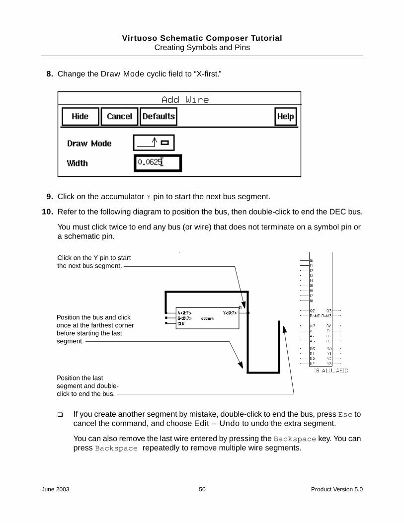
8. Change the Draw Mode cyclic field to “X-first.”
9. Click on the accumulator Y pin to start the next bus segment.
10. Refer to the following diagram to position the bus, then double-click to end the DEC bus.
You must click twice to end any bus (or wire) that does not terminate on a symbol pin ora schematic pin.
❑ If you create another segment by mistake, double-click to end the bus, press Esc tocancel the command, and choose Edit – Undo to undo the extra segment.
You can also remove the last wire entered by pressing the Backspace key. You canpress Backspace repeatedly to remove multiple wire segments.
Click on the Y pin to startthe next bus segment.
Position the bus and clickonce at the farthest cornerbefore starting the lastsegment.
Position the lastsegment and double-click to end the bus.
June 2003 50 Product Version 5.0

Virtuoso Schematic Composer TutorialCreating Symbols and Pins
Adding the Output Bus
You also use the “X-first” mode to place the output bus.
1. Click on the OUT<0:3> pin to start the output bus.
2. Refer to the diagram to position the bus, then double-click to place it.
Notice that you do not connect the two buses. In the next section, you will use nets toconnect them to the ALU.
Position the bus anddouble-click to end it.
Click on the OUT<0:3>pin to start the bus.
June 2003 51 Product Version 5.0

Virtuoso Schematic Composer TutorialCreating Symbols and Pins
June 2003 52 Product Version 5.0

Virtuoso Schematic Composer Tutorial
4Adding Wires, Checking the Schematic,and Attaching a Border
In this chapter, you finish the top_level schematic. You can save and quit at any time andcome back later.
In this chapter, you will learn how to
■ Wire the design
■ Name the nets and buses
■ Check the schematic for errors and establish electric connectivity
■ Attach a border to the schematic
Wiring the Input Pins
In this section, you wire the instances, pins, and buses using the Add – Wire (narrow)command from the object-sensitive menu (OSM).
1. Zoom in to more easily connect the nets.
June 2003 53 Product Version 5.0
Virtuoso Schematic Composer TutorialAdding Wires, Checking the Schematic, and Attaching a Border
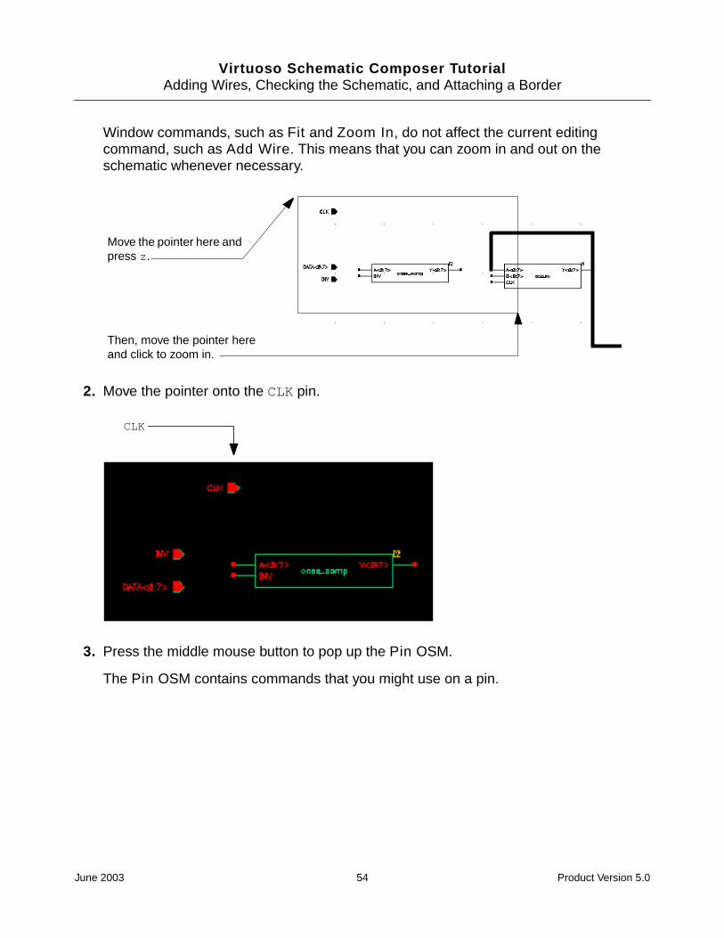
Window commands, such as Fit and Zoom In, do not affect the current editingcommand, such as Add Wire. This means that you can zoom in and out on theschematic whenever necessary.
2. Move the pointer onto the CLK pin.
3. Press the middle mouse button to pop up the Pin OSM.
The Pin OSM contains commands that you might use on a pin.
Move the pointer here andpress z.
Then, move the pointer hereand click to zoom in.
CLK
June 2003 54 Product Version 5.0

Virtuoso Schematic Composer TutorialAdding Wires, Checking the Schematic, and Attaching a Border
4. Choose Wire (narrow) and release the button.
Because you popped up the Pin OSM on the CLK pin (and Infix is on), the net from theCLK pin is already started. You see it when you move the pointer.
June 2003 55 Product Version 5.0

Virtuoso Schematic Composer TutorialAdding Wires, Checking the Schematic, and Attaching a Border
5. Route these nets, as shown in the figure (click at the beginning and ending points foreach net).
❑ Connect the CLK pin to the accumulator CLK pin.
❑ Connect the INV pin to the INV pin on the one’s complement module.
❑ Connect the DATA<0:7> pin to the A<0:7> pin on the one’s complement module.
❑ Connect the Y<0:7> pin on the one’s complement module to the B<0:7> pin on theaccumulator.
Wiring the ALU
Next you will wire the ALU. As always, it is easier to perform your work when you are zoomedin on the area where you are working.
1. Press f (Fit) to display the entire schematic.
June 2003 56 Product Version 5.0

Virtuoso Schematic Composer TutorialAdding Wires, Checking the Schematic, and Attaching a Border
2. Zoom on the area shown in the figure.
The zoomed-in portion of the schematic appears.
3. To wire the ALU, click on the beginning and ending points for each net as shown in thefigure.
A solder dot appears when you successfully tap one of the buses.
The nets you have just placed are not tapped into a specific signal in either bus until youassign names to the nets. You will assign those names in the next section.
Zoom in onthis area.
Route these eightnets.
Route these four nets.
June 2003 57 Product Version 5.0

Virtuoso Schematic Composer TutorialAdding Wires, Checking the Schematic, and Attaching a Border
Naming the Nets
In this section, you name the nets tapping the buses. The nets that connect to the pins inheritthe pin names and do not need names. You will use the name array feature, which lets youattach multiple names at one time.
If you zoomed in to fit the entire schematic into the window at the end of the previous section,you need to zoom in again on the nets tapping the buses.
1. Place the pointer over one of the nets tapping the buses.
2. Press the middle mouse button over the wire and the Wire OSM pops up.
3. Choose Add Name from the OSM.
ChooseAddName.
June 2003 58 Product Version 5.0

Virtuoso Schematic Composer TutorialAdding Wires, Checking the Schematic, and Attaching a Border
The Add Wire Name form appears.
4. In the Names field, type names for all these nets by specifying two name arrays, <0:7>and <0:3>.
These arrays identify the bit ranges you are naming.
The ALU pins tap the DEC bus and the OUT bus as follows:
❑ Pins A0 through A3 tap bits 0 through 3 from the DEC bus.
❑ Pins D0 through D3 tap bits 4 through 7 from the DEC bus.
❑ Pins Y0 through Y3 tap bits 0 through 3 to the out bus.
5. On the Add Wire Name form, do the following:
❑ Set Bus Expansion to on.
The Bus Expansion button tells the system to extract individual bit names from thearray names. The first name will be <0>, the second name will be <1>, and so on.
❑ Set Placement to multiple.
Setting the Placement button to multiple tells the system that you want to place anarray of names, rather than one name at a time.
June 2003 59 Product Version 5.0

Virtuoso Schematic Composer TutorialAdding Wires, Checking the Schematic, and Attaching a Border
Placing the Input Wire Names
1. Position the pointer on the first net to be named.
The <0> name follows the pointer (see the figure).
Important
Follow the instructions in this section carefully. Check the figure before you do astep. Placing multiple names is easy once you know how, but it can be tricky the firsttime.
2. Click on the net to assign the name to it.
Once the name is assigned, it remains with the net when you stretch or move the net.
A rubberband line, connected to the first wire, appears when you move the pointer. Youwill use the rubberband line to assign names to the remaining nets, as described in thenext step.
Click on the netto assign the<0> name.
June 2003 60 Product Version 5.0

Virtuoso Schematic Composer TutorialAdding Wires, Checking the Schematic, and Attaching a Border
3. Move the pointer to the bottom net to display and position the remaining names.
4. Click on the bottom net to assign the remaining names.
Dropped a bit? If you accidentally click on a net other than the last one, the systemsaves the remaining wire names and allows you to continue placing them until all eightnames for the bus wires have been assigned. If you have any other problems withautomatic name placement, undo your last steps and try again. If you do not name allthe nets, the system issues an error message when you check the design.
Placing the Output Wire Names
Assign the output names just as you placed the input names.
Move thepointer to thebottom net toinclude theremaining nets.
Click on the bottomnet to assign theremaining names.
The <0> name for theoutput net now followsthe pointer.
June 2003 61 Product Version 5.0

Virtuoso Schematic Composer TutorialAdding Wires, Checking the Schematic, and Attaching a Border
1. Click to place the <0> name on the net connecting the Y0 pin (see the figure).
2. Move the pointer to the bottom net (connecting the Y3 pin) to include the remaining nets.
3. Click on the bottom net to assign the remaining names.
4. Press Esc to cancel the Add – Wire Name command.
You have now completed naming the nets.
5. Zoom out to fit the entire schematic.
Checking the Schematic
Up to this point, you have created a drawing of the schematic. In this section, you use theCheck and Save command to do the following:
■ Check your design for errors
■ Establish electrical connectivity
■ Save the design and connectivity information in the system database
You might have noticed that you have not yet named the DEC bus. As a result, Check will findan error in your schematic.
Once you have established electrical connectivity with the Check and Save command, youcan use the design as input to other tools, such as a simulator.
Similarly, placethese names.
June 2003 62 Product Version 5.0

Virtuoso Schematic Composer TutorialAdding Wires, Checking the Schematic, and Attaching a Border
Setting Up the Check Rules
In this section, you set the rules for checking the schematic to ignore floating inputs andoutputs. Your design is incomplete, with floating inputs and outputs, and you do not want tobe presented with a long list of error messages.
1. Choose Check – Rules Setup.
The Setup Schematic Rules Checks form appears. This form identifies the conditions tobe flagged with warning or error messages.
2. Turn on the ignored buttons for floating nets and pins
3. Click OK.
June 2003 63 Product Version 5.0

Virtuoso Schematic Composer TutorialAdding Wires, Checking the Schematic, and Attaching a Border
Running Check and Save
1. Choose the Check and Save icon on the left side of the schematic window.
The Check program checks the schematic. Because you have omitted the DEC busname, Check finds errors in your design. As a result, the following occurs:
❑ The errors on the schematic start blinking with error markers.
❑ The Command Interpreter Window (CIW) shows the error messages.
❑ A dialog box appears, giving the number of errors.
2. Click Close.
Click here.
June 2003 64 Product Version 5.0

Virtuoso Schematic Composer TutorialAdding Wires, Checking the Schematic, and Attaching a Border
A second dialog box appears, questioning your decision to save a design with errors.
3. Click Yes.
The Virtuoso® schematic composer software saves the design and displays aconfirmation message in the CIW:
"tutorial top_level schematic" saved.
June 2003 65 Product Version 5.0

Virtuoso Schematic Composer TutorialAdding Wires, Checking the Schematic, and Attaching a Border
The following output is an example of the errors that might exist:
In the next section, you display the error message for each error marker.
Identifying the Errors
1. Choose Check – Find Marker.
June 2003 66 Product Version 5.0

Virtuoso Schematic Composer TutorialAdding Wires, Checking the Schematic, and Attaching a Border
The Find Marker form appears, displaying the error messages. The first message on theFind Marker form is selected.
2. To magnify the location of specific error markers, turn on Zoom To Markers.
3. Position the schematic window and the Find Marker form side by side.
June 2003 67 Product Version 5.0

Virtuoso Schematic Composer TutorialAdding Wires, Checking the Schematic, and Attaching a Border
The error is caused by the missing name for the DEC bus. The system cannot determinewhich signal is being tapped. Because any signal is a possible candidate, the systemshows the whole design and does not zoom in on one section.
4. Click Next to see the next error.
You can continue clicking on Next or Previous to cycle through the messages. When youget to an illegal bus reference message, the schematic window will zoom in onthe area with the flashing markers.
The one marker in a different color corresponds to the selected error message. All othermarkers remain white.
All the errors are caused by the missing bus name. In the next section, you create themissing name.
5. Click Cancel on the Find Marker form to cancel the command.
June 2003 68 Product Version 5.0

Virtuoso Schematic Composer TutorialAdding Wires, Checking the Schematic, and Attaching a Border
The forms disappear. The markers remain. They will be automatically deleted later whenyou run Check and Save after naming the bus.
Naming the DEC Bus
1. Choose Add – Wire Name.
The Add Wire Name form appears.
2. In the Names field, type DEC<0:7>.
3. Position the name above the bus and click to place it.
Place the name.
June 2003 69 Product Version 5.0

Virtuoso Schematic Composer TutorialAdding Wires, Checking the Schematic, and Attaching a Border
4. Press Esc to cancel the Add – Wire Name command.
5. Choose the Check and Save icon to rerun the Check program.
This time, no errors occur on the DEC<0:7> bus. The system saves the design with itsconnectivity information. Confirmation messages appear in the CIW.
You have completed the design. In the next section, you attach a border to the schematic.
Creating a Sheet Border and Title
You can create a border to your schematic and a title block to identify it. Attaching a borderconsists of these three steps:
■ Creating the border
■ Centering the design within the border
■ Naming the schematic
Creating a Border
1. Choose Sheet – Edit Size.
The Change Sheet Border Size form appears.
2. Change Border Size from A to B.
3. Click OK.
Depending on where you placed the instances, a dialog box might appear.
June 2003 70 Product Version 5.0

Virtuoso Schematic Composer TutorialAdding Wires, Checking the Schematic, and Attaching a Border
The B-sized border appears on the schematic. The border might cut through part of thedesign, as illustrated in the following figure.
Centering the Schematic within the Border
If the border cuts through part of your schematic, you must move the design to center it. Ifyour design is already centered within the border, you can skip this section.
Reading: master top_level schematic 0.1
The borderappears on theschematic.
The schematicmight not becentered within theborder.
June 2003 71 Product Version 5.0

Virtuoso Schematic Composer TutorialAdding Wires, Checking the Schematic, and Attaching a Border
1. Select the entire schematic by moving the pointer above the design, click, and drag toform a box around the design.
The entire schematic is selected.
2. Press M.
A bright box appears around the schematic.
3. Move the pointer to position the design inside the border.
The shape of the design follows the pointer.
4. Click to place the design.
The design appears within the border, and the Move box disappears.
Reading: master top_level schematic 0.1
First click here.Then, drag thebox to here toselect theschematic.
June 2003 72 Product Version 5.0

Virtuoso Schematic Composer TutorialAdding Wires, Checking the Schematic, and Attaching a Border
5. Click on the schematic window, outside the schematic, to deselect it.
Adding a Name to the Title Block
1. Choose Sheet – Edit Title.
Reading: master top_level schematic 0.1
Move the pointer to centerthe design and click toplace it.
Click outside the design todeselect it.
June 2003 73 Product Version 5.0

Virtuoso Schematic Composer TutorialAdding Wires, Checking the Schematic, and Attaching a Border
The Schematic Title Block Properties form appears.
2. Type your company name and the schematic title.
3. Click OK.
The company name and schematic title appear in the title block of the schematic design.
4. Press S to save your design.
5. Choose Window – Close to close the schematic window.
The window closes.
You have now completed and checked in the top-level schematic for the tutorial design. InChapter 5, “Creating the Accumulator Schematic,” you will create the accumulator schematic.
June 2003 74 Product Version 5.0

Virtuoso Schematic Composer TutorialAdding Wires, Checking the Schematic, and Attaching a Border
June 2003 75 Product Version 5.0

Virtuoso Schematic Composer TutorialAdding Wires, Checking the Schematic, and Attaching a Border
June 2003 76 Product Version 5.0

Virtuoso Schematic Composer Tutorial
5Creating the Accumulator Schematic
In this chapter, you create the schematic for the accumulator in the tutorial design, using thefollowing procedures:
■ Add 4-bit adders, an 8-bit register, a power symbol, and a ground symbol
■ Wire the schematic
■ Add the pins
■ Name the nets
About the Accumulator
The accumulator schematic contains the following:
■ Two 4-bit adders
■ One clocked 8-bit register
■ Three schematic input pins and one schematic output pin
June 2003 77 Product Version 5.0

Virtuoso Schematic Composer TutorialCreating the Accumulator Schematic
■ Three 8-bit buses, represented by the thick lines
You will learn how to
■ Automatically create a schematic cellview
You will automatically create the schematic cellview for the accumulator, based on theaccumulator symbol on the top-level schematic. The new schematic cellview will containschematic pins based on the pins defined for the accumulator symbol.
■ Add instances for standard functions to the schematic
■ Create pin-to-pin connections between two parts
■ Wire multiple pins with one command by creating wire copies
If you have problems executing a command, remember to look at the prompt in the CommandInterpreter Window (CIW).
Adding Instances
In this section, you automatically create the accum schematic cellview. You base theschematic on the accumulator symbol in the top-level schematic. The new schematiccontains the pins defined for the accumulator symbol.
Follow these steps to create the accum schematic cellview.
input buses
4-bit adder
4-bit adder
8-bit register
output bus
June 2003 78 Product Version 5.0

Virtuoso Schematic Composer TutorialCreating the Accumulator Schematic
1. Start the Virtuoso® schematic composer software (unless it is already running) and setyour environment options with Options – User Preferences.
Set Infix and scroll bars to on and change the undo limit to 10.
2. In the tutorial library, choose Design – Open to open the top-level schematic for editing.
3. Choose Design – Create Cellview – From Instance.
The prompt line at the bottom of the schematic window is
Point at instance to generate view.
4. Click on the accum instance to create the accum schematic cellview.
The Cellview From Instance form appears.
5. Make sure the Display Cellview option is selected.
6. Check that View Name is set to schematic and click OK.
The Create Schematic form appears.
June 2003 79 Product Version 5.0

Virtuoso Schematic Composer TutorialCreating the Accumulator Schematic
7. Set Size to B and click OK.
8. Open the accum cellview.
The accum cellview is displayed automatically in another schematic window. It containsthe schematic input and output pins created by the Create Cellview command, setinside a B-sized schematic border.
You are now ready to start creating the schematic.
Adding Two 4-Bit Adder Symbols
1. Choose Add – Instance.
June 2003 80 Product Version 5.0

Virtuoso Schematic Composer TutorialCreating the Accumulator Schematic
The Add Instance form appears.
2. In the Library field, type TTL_tutor.
The TTL_tutor library contains symbols for the functions used in the tutorial design. Thegeneric function numbers for these symbols appear in the Instance window.
3. In the Cell field, type 283.
The adder instance appears in the schematic window.
4. Position the first adder instance at the bottom of the screen and click to place it.
You will place the second adder instance upside down. The instance shape continues tofollow the pointer.
June 2003 81 Product Version 5.0

Virtuoso Schematic Composer TutorialCreating the Accumulator Schematic
5. Click on Upside Down on the Add Instance form.
6. Position the second instance above the first instance and click to place it.
Adding the 8-Bit Register Symbol
1. In the Cell field, type 373 for instance I3 and click on Upside Down to turn off thefeature from the last step.
Position the secondsymbol above thefirst symbol.
Position the first symboland click to place it.
June 2003 82 Product Version 5.0

Virtuoso Schematic Composer TutorialCreating the Accumulator Schematic
2. Zoom in and place the register instance so that you create a pin-to-pin connection withthe top adder instance.
❑ Position the register instance so that the top four input pins are touching the fourSUM output pins of the top adder instance.
❑ Check that the register instance is positioned properly (not upside down).
3. Press f to fit the entire schematic in the window.
In the next section, you add the power and ground symbol.
Adding Power and Ground Symbols
To add power and ground symbols, do the following:
1. In the Library field, type basic.
June 2003 83 Product Version 5.0

Virtuoso Schematic Composer TutorialCreating the Accumulator Schematic
The power and the ground symbols are in the basic library. This library is supplied withthe schematic composer software.
2. In the Cell field, type PWR.
3. Position the power symbol close to the C0 pin on the bottom adder instance and click toplace it.
The shape of the PWR symbol continues to follow the pointer.
4. In the Cell field, type GND.
Place the powersymbol close to the C0pin.The shape of the PWRsymbol continues tofollow the pointer.
June 2003 84 Product Version 5.0
Virtuoso Schematic Composer TutorialCreating the Accumulator Schematic
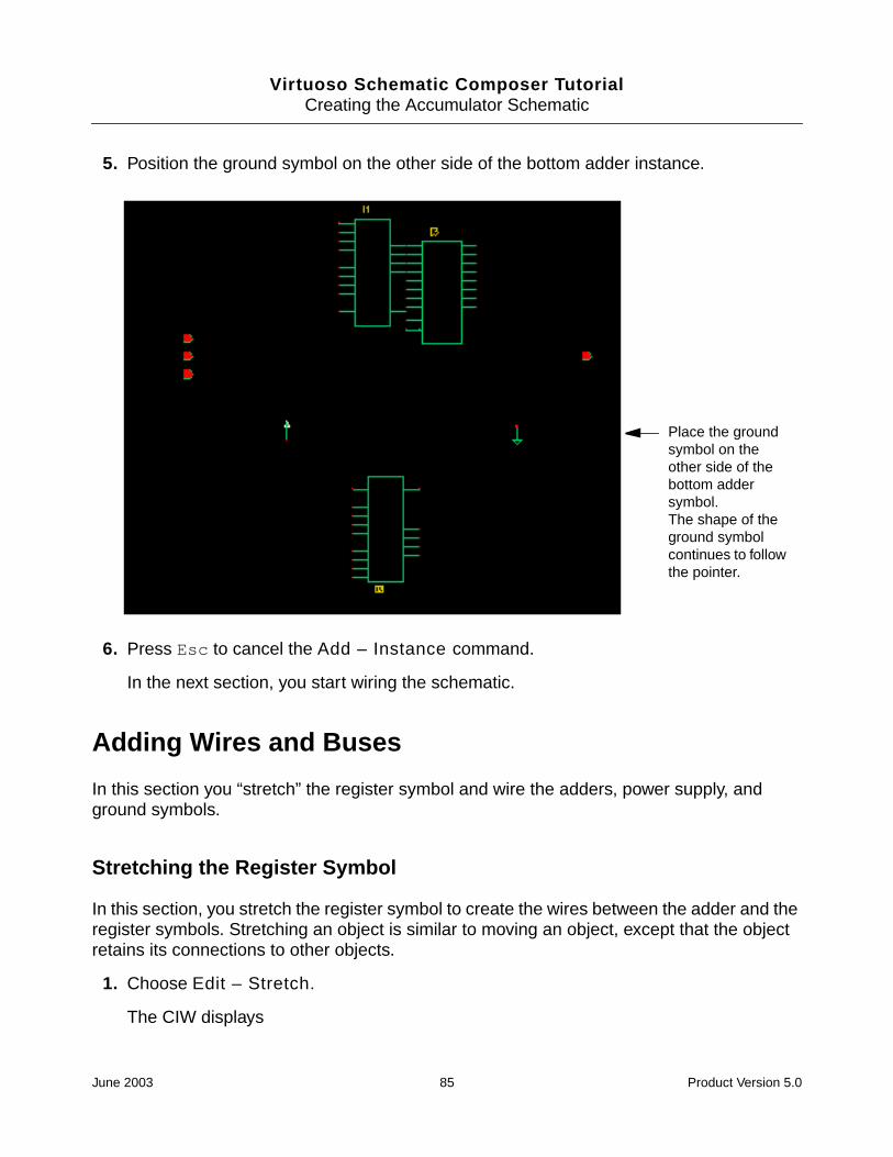
5. Position the ground symbol on the other side of the bottom adder instance.
6. Press Esc to cancel the Add – Instance command.
In the next section, you start wiring the schematic.
Adding Wires and Buses
In this section you “stretch” the register symbol and wire the adders, power supply, andground symbols.
Stretching the Register Symbol
In this section, you stretch the register symbol to create the wires between the adder and theregister symbols. Stretching an object is similar to moving an object, except that the objectretains its connections to other objects.
1. Choose Edit – Stretch.
The CIW displays
Place the groundsymbol on theother side of thebottom addersymbol.The shape of theground symbolcontinues to followthe pointer.
June 2003 85 Product Version 5.0

Virtuoso Schematic Composer TutorialCreating the Accumulator Schematic
Point at object to stretch.
2. Click on the register symbol to select it for the stretch.
The CIW displays
Point at destination point for stretch.
3. Reposition the register symbol.
Dotted flight lines show the connections between the two symbols.
4. Click to place the register symbol.
The system automatically routes the nets.
Position the registersymbol with the pointer.Dotted flight lines showthe connection.
Click to route thenets.
June 2003 86 Product Version 5.0

Virtuoso Schematic Composer TutorialCreating the Accumulator Schematic
Wiring the Adders, Power Supply, and Ground Symbols
1. Zoom in on the area shown in the figure.
2. Choose Add – Wire (narrow).
You may need to press the F3 function key to bring up the form and set Draw Mode toroute.
In the next steps, you wire the four lower input pins on the register symbol to the fourSUM output pins on the lower adder symbol.
Zoom in on thisarea.
June 2003 87 Product Version 5.0

Virtuoso Schematic Composer TutorialCreating the Accumulator Schematic
3. Route the SUM4 pin on the lower adder symbol to the register 4D pin. Click at thebeginning and the ending points for the wire.
4. Similarly, route the following nets:
SUM3 to 3DSUM2 to 2DSUM1 to 1DC0 (on the top adder) to C4 (on the bottom adder)
Route theSUM4pin to the4D pin.
June 2003 88 Product Version 5.0
Virtuoso Schematic Composer TutorialCreating the Accumulator Schematic
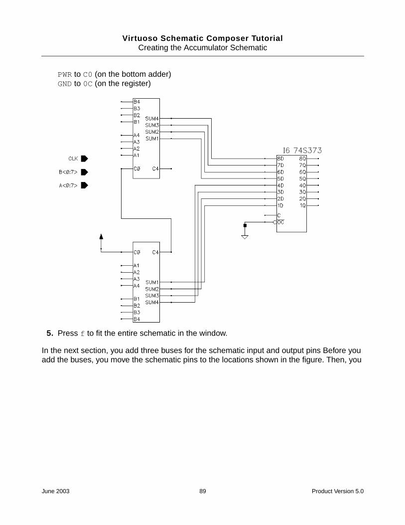
PWR to C0 (on the bottom adder)GND to 0C (on the register)
5. Press f to fit the entire schematic in the window.
In the next section, you add three buses for the schematic input and output pins Before youadd the buses, you move the schematic pins to the locations shown in the figure. Then, you
June 2003 89 Product Version 5.0

Virtuoso Schematic Composer TutorialCreating the Accumulator Schematic
draw the buses using the “X-first” drawing mode, just as you did when you added buses tothe top-level schematic.
Moving the Schematic Pins for Space
1. Choose Edit – Move.
2. Select the CLK, B<0:7>, and A<0:7> input pins (drag a box around them with themouse).
3. Click on the pins you selected to verify that you want to move them.
4. Position the pins in the top left corner of the schematic (see the figure) and click to placethem.
5. Select the Y<0:7> output pin by clicking on it.
B input bus
Y output bus
A input bus
June 2003 90 Product Version 5.0

Virtuoso Schematic Composer TutorialCreating the Accumulator Schematic
6. Position the output pin in the top right corner and click to place it.
Editing commands, such as Move, work differently depending on whether you select thecommand first or select the objects first. When you select the command first, the objectsare automatically deselected after the command executes, but the command remainsactive. When you select the objects first, the objects are not deselected, but thecommand is automatically canceled.
Drawing the Buses
You use the same procedure that you used to create the top-level buses: see “Adding theDEC Bus” on page 47.
1. Choose Add – Wire (wide).
2. Press the F3 function key to open the Add Wire form.
Move theschematic pins asshown here.
June 2003 91 Product Version 5.0

Virtuoso Schematic Composer TutorialCreating the Accumulator Schematic
3. Set the Draw Mode cyclic field to the “X-first” drawing mode.
4. Draw the buses, clicking twice to end each bus.
In the next section, you wire the CLK pin and tap the buses to connect the symbol pins. Tospeed up the process, you use the Copy command to copy wire arrays.
Wiring the CLK Pin
1. Choose Add – Wire (narrow).
2. Press the F3 function key to open the Add Wire form.
3. Click the Defaults button to set Draw Mode to full routing.
Draw thesethreebuses.
June 2003 92 Product Version 5.0

Virtuoso Schematic Composer TutorialCreating the Accumulator Schematic
4. Click the Hide button.
5. Route the CLK pin to the C input pin on the register symbol.
You must place the first segment yourself (to help the router place it appropriately).
Wiring the Adders
1. Route these nets.
Check your work carefully to be sure that you connect each pin to the correct bus.
❑ Pin B4 on the top adder symbol to the B bus
❑ Pin A4 on the top adder symbol to the A bus
❑ Pin A1 on the bottom adder symbol to the A bus
❑ Pin B1 on the bottom adder symbol to the B bus
Route this net.
June 2003 93 Product Version 5.0
Virtuoso Schematic Composer TutorialCreating the Accumulator Schematic
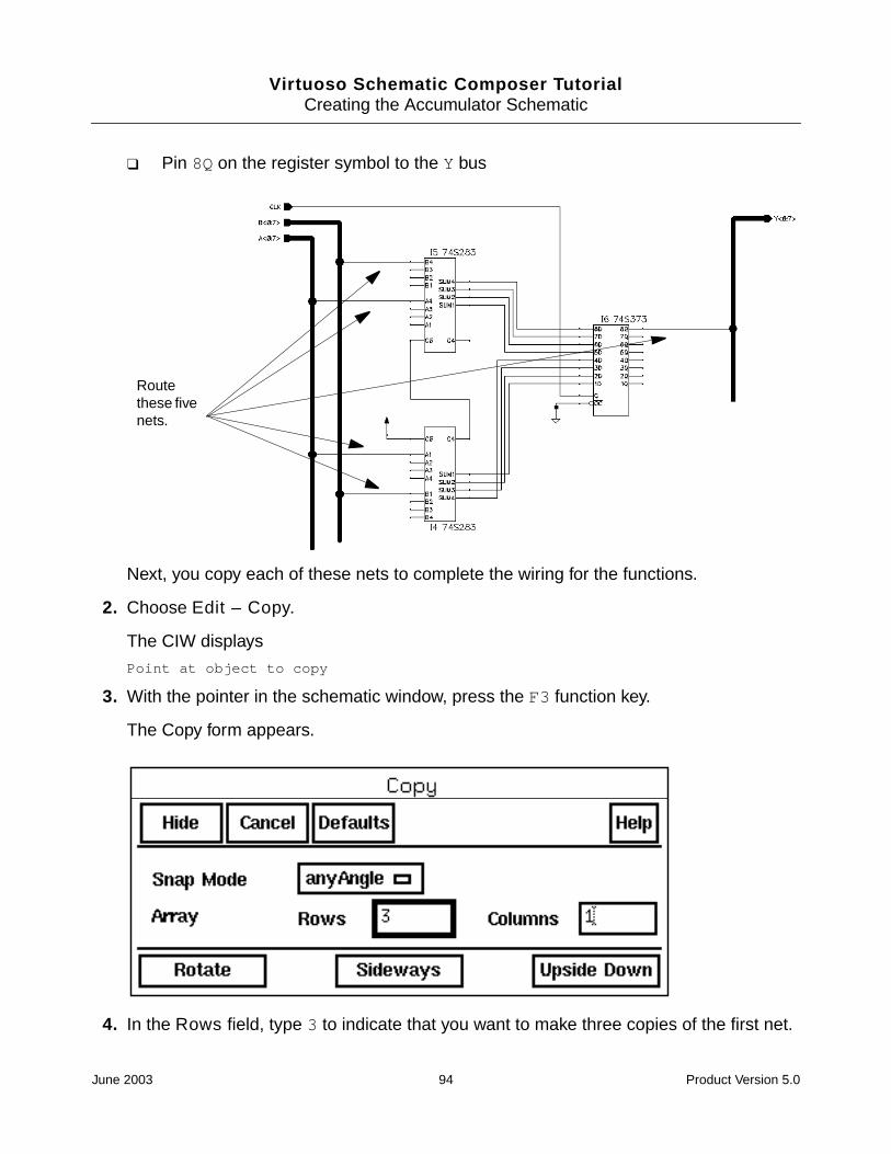
❑ Pin 8Q on the register symbol to the Y bus
Next, you copy each of these nets to complete the wiring for the functions.
2. Choose Edit – Copy.
The CIW displays
Point at object to copy
3. With the pointer in the schematic window, press the F3 function key.
The Copy form appears.
4. In the Rows field, type 3 to indicate that you want to make three copies of the first net.
Routethese fivenets.
June 2003 94 Product Version 5.0

Virtuoso Schematic Composer TutorialCreating the Accumulator Schematic
5. Click on the top input net on the top adder symbol to indicate that you want to copy it.
A second net appears, highlighted in yellow.
6. Position the second net and click to place it.
The system anticipates the next two copies, giving you two more nets to placesimultaneously.
7. Position the remaining nets with the pointer.
8. Click to place them.
Solder dots appear, indicating that the nets are connected to the bus.
9. Copy and place the remaining input nets.
Click on thisnet to copy it.
June 2003 95 Product Version 5.0

Virtuoso Schematic Composer TutorialCreating the Accumulator Schematic
Start by clicking on the first net of each set as you did before. Then, position and click toplace each net copy. Watch the prompt line to keep track of your next step.
In the next section, you create a seven-wire array for wiring the register.
Wiring the Register
1. On the Copy form, type 7 in the Rows field to indicate that you want to create an arrayof seven nets.
Similarly,copy andplace thesenets.
June 2003 96 Product Version 5.0
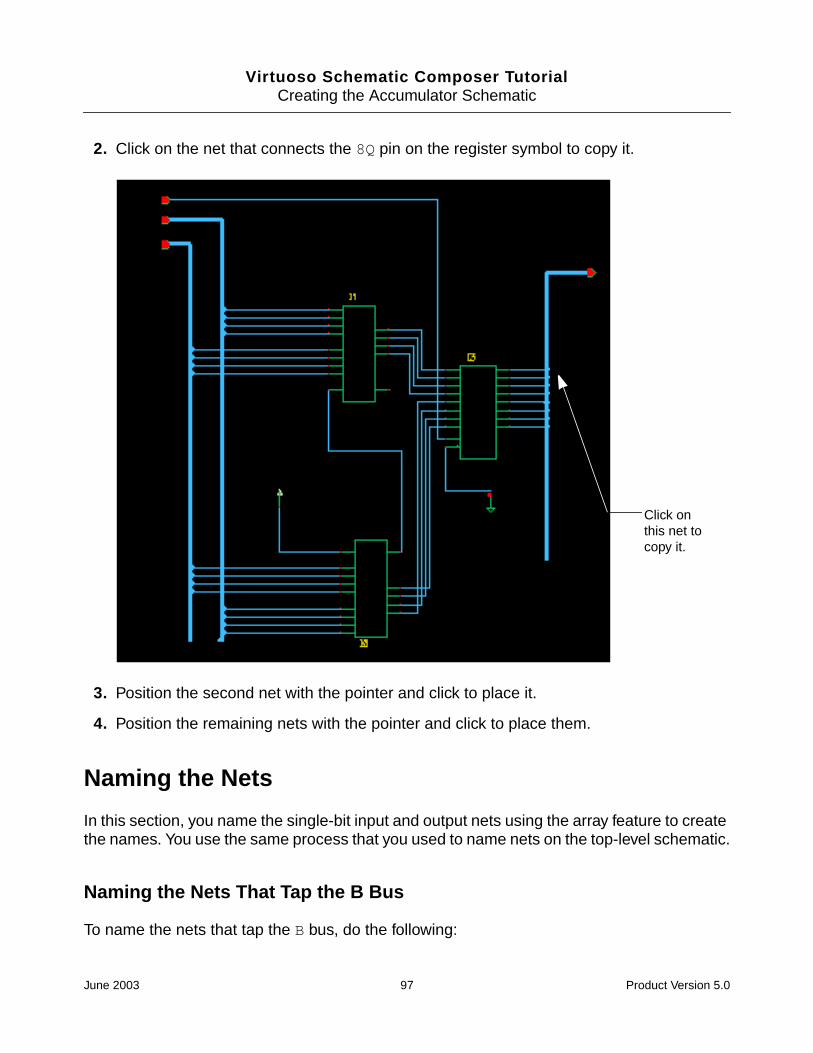
Virtuoso Schematic Composer TutorialCreating the Accumulator Schematic
2. Click on the net that connects the 8Q pin on the register symbol to copy it.
3. Position the second net with the pointer and click to place it.
4. Position the remaining nets with the pointer and click to place them.
Naming the Nets
In this section, you name the single-bit input and output nets using the array feature to createthe names. You use the same process that you used to name nets on the top-level schematic.
Naming the Nets That Tap the B Bus
To name the nets that tap the B bus, do the following:
Click onthis net tocopy it.
June 2003 97 Product Version 5.0

Virtuoso Schematic Composer TutorialCreating the Accumulator Schematic
1. Choose Add Wire Name.
The Add Wire Name form appears.
You need to create three sets of seven names:
❑ One set for the A pins on the adder
❑ One set for the B pins on the adder
❑ One set for the Q pins on the register
2. In the Names field, type <0:7> <0:7> <0:7>.
3. Turn on Bus Expansion.
4. Set Justification to centerCenter.
5. Set Placement to multiple.
The buses inherit the schematic pin names. The nets tapping the buses inherit the busname, which is why you name them with the bit number only.
6. Zoom in on the bottom nets of the B bus.
June 2003 98 Product Version 5.0

Virtuoso Schematic Composer TutorialCreating the Accumulator Schematic
It is much easier to place the names when you zoom in.
7. Place the names for bits 0–3 tapped from the B bus.
Bits 0–3 from the B bus are input into pins B1 through B4, respectively, on the bottomadder symbol.
8. Press f to fit the entire schematic in the window.
B bus
Place names 0 through 3.
June 2003 99 Product Version 5.0

Virtuoso Schematic Composer TutorialCreating the Accumulator Schematic
9. Zoom in on the top nets for the B bus.
10. Place the names for bits 4–7 tapped from the B bus, starting with the bottom net.
Bits 4–7 from the B bus are input into pins B1 through B4, respectively, on the top adder.
11. Press f to fit the entire schematic in the window.
Zoom in on thisarea.
Place names 4through 7starting withthe bottom net.
June 2003 100 Product Version 5.0

Virtuoso Schematic Composer TutorialCreating the Accumulator Schematic
12. Zoom in on the bottom nets for the A bus.
13. Place names 0–3.
14. Press f to fit the entire schematic in the window.
Zoom in on thisarea
Place names 0through 3.
June 2003 101 Product Version 5.0

Virtuoso Schematic Composer TutorialCreating the Accumulator Schematic
15. Zoom in on the top nets for the A bus.
16. Place the names for bits 4–7 tapped from the A bus, starting with the bottom net.
Bits 4–7 from the A bus are input into pins A1 through A4, respectively, on the top adder.
17. Press f to fit the entire schematic in the window.
Zoom in on thearea in this box.
Place names 4 through7 starting with thebottom net.
June 2003 102 Product Version 5.0

Virtuoso Schematic Composer TutorialCreating the Accumulator Schematic
Naming the Nets That Tap the Y Bus
1. Zoom in on the nets tapping the Y bus.
2. Place the names for the nets to the Y bus.
Bits <0> through <7> are output from pins 1Q through 8Q, respectively.
3. Press f to fit the entire schematic in the window.
4. Press Esc to cancel the command.
You have now named all the nets connected to the buses. In the next section, you checkthe schematic for errors and establish the electrical connectivity for the design.
Checking the Schematic
In this section, you execute the Check and Save command to do the following:
■ Check your design for errors
■ Establish electrical connectivity
Place these namesstraight up.
June 2003 103 Product Version 5.0

Virtuoso Schematic Composer TutorialCreating the Accumulator Schematic
■ Save the design and its connectivity information in the schematic composer database
To check your schematic, do the following:
1. Choose Check – Rules Setup.
The Setup Schematic Rules Checks form appears.
2. Set the form to its default settings by clicking Defaults.
3. Click OK.
4. Click the Check and Save icon.
The rules checker finds four problems.
Follow the steps in “Checking the Schematic” on page 62 to check your errors.
5. Fix the errors.
Several warnings result from stubs projecting off the ends of the buses. Delete thesestubs by selecting each one and pressing Delete.
One error is due to the floating carry output on the 74S373 register symbol. You caneither turn off the checking for floating output pins or tie the output to a pull-up resistortied to PWR. For the default Schottky technology, a value of 1 Kohms is best.
You also need to edit the pullup and pulldown resistors. If you use pullup resistor as thepullup resistor provided in the sample library, you need to change the output pin to input/output. The situation is the same with the pulldown resistor. However, if you connect asimple resistor to PWR or GND, then the error is fixed.
6. Execute Check and Save again.
The Check program checks and saves the design. The CIW displays
Schematic check completed with no errors. "accum schematic" saved.
You have completed the schematic.
The parts used in this design include Verilog® simulation information. If you want to simulateyour design with Verilog software, continue with Chapter 7, “Preparing the top_levelSchematic for Simulation,” and follow the steps described there to prepare your design forsimulation.
June 2003 104 Product Version 5.0

Virtuoso Schematic Composer Tutorial
6Creating the Analog Amplifier Schematic
In this chapter, you create the schematic for a single transistor amplifier with analogcomponents using the following procedures:
■ Use a bottom-up design approach in the Virtuoso® schematic composer software
■ Use a standard Cadence® parts library
■ Create an analog design from discrete instances
■ Use the Add Instance and Edit Object Properties forms to change the values of instanceparameters
■ Use the Component Description Format (CDF) editor to create a new instance parameter
■ Create a new symbol cellview automatically, based on an existing schematic cellview
■ Add symbols from a standard Cadence library
■ Select and move objects and wired pins with dynamic editing
June 2003 105 Product Version 5.0

Virtuoso Schematic Composer TutorialCreating the Analog Amplifier Schematic
About the Analog Amplifier Schematic
The amplifier schematic contains
■ Four resistors
■ One npn transistor
■ One output capacitor
■ One output pin and one input pin
Creating the amp Schematic Cellview
In this section, you create the amp schematic cellview from discrete parts in a bottom-updesign.
1. Start the Virtuoso schematic composer software (unless it is already running).
2. From the Command Interpreter Window (CIW), choose Options – User Preferencesto set the environment options.
Set Infix and scrollbars to on and change the undo limit to 10.
Because no amp schematic cellview exists, you must create it.
3. Choose File – New – Cellview.
input pin
npn transistor
resistor
output capacitor
output pin
June 2003 106 Product Version 5.0

Virtuoso Schematic Composer TutorialCreating the Analog Amplifier Schematic
The Create New File form opens.
4. Set the Library Name cyclic field to tutorial.
5. In the Cell Name field, type amp.
6. In the View Name field, type schematic.
7. Set the Tool cyclic field to Composer – Schematic.
8. Click OK.
The schematic editor opens, displaying an empty design window.
You are now ready to create the amp schematic.
Adding Symbols for the Four Resistors
1. Choose Add – Instance.
The Add Instance form appears.
2. In the Library field, type analogLib.
The analogLib library contains cells for analog functions.
3. In the Cell field, type res.
June 2003 107 Product Version 5.0

Virtuoso Schematic Composer TutorialCreating the Analog Amplifier Schematic
The Add Instance form expands to reveal an instance parameters section.
4. Position the first resistor symbol, R0, at the bottom of the schematic window and click toplace it.
June 2003 108 Product Version 5.0

Virtuoso Schematic Composer TutorialCreating the Analog Amplifier Schematic
5. Place the remaining three resistors (R1, R2, R3) in the pattern shown.
6. With the pointer in the schematic window, press Esc to cancel the Add – Instancecommand.
Changing Resistor Parameter Values
The analog instances in the amplifier design are generic devices with a few basic defaultvalues for their parameters. Each resistor that you add from the analogLib library has adefault resistance value of 1 Kohms (ohms is implied). The resistance is defined as theparameter r.
You must change the resistance of each resistor from its default value to the value needed inthe design.
1. Choose Edit – Properties – Objects from the schematic editor window.
The following message appears in the prompt at the bottom of the schematic editorwindow and at the bottom of the CIW:
Point at object to edit its properties.
2. Move the pointer over the resistor R1 and click.
June 2003 109 Product Version 5.0

Virtuoso Schematic Composer TutorialCreating the Analog Amplifier Schematic
The Edit Object Properties form appears.
If the Edit Object Properties form covers the schematic, move it to one side.
The message in the CIW changes to
Edit the properties on the form or select another object.
3. In the Resistance field, type 30K.
4. Click Apply.
The schematic display changes, showing the new r value of 30K for R1.
Some instanceparameters start withdefault values.
The user data sectionindicates which cellinstance you areworking on.
June 2003 110 Product Version 5.0

Virtuoso Schematic Composer TutorialCreating the Analog Amplifier Schematic
5. Move the pointer back in the design window and click on R2.
6. In the Resistance field, type 4K.
7. Click Apply.
8. Repeat the process for R3 and R0. Set R3 to 2K and R0 to 15K.
You can use K and other standard notation when entering instance parameter values. Ifyou type a long number such as 30,000, the system puts 30,000 on the schematic. If youerase the word ohms, don’t worry. Ohms is automatically assumed for resistance. If youcancel the Edit Object Properties form and open it again, the word ohms has returnedto the Resistance field.
9. Click Cancel to close the Edit Object Properties form.
The Edit Object Properties form showed many other parameters associated with the resistorcell. These parameters are titled CDF Parameters because CDF, Component DescriptionFormat, is the format used in Cadence software to describe the features and behavior of eachtype of device. The CDF description for a cell can include information for simulation, layout,and label display. You will use the CDF editor later in this chapter. For more information aboutCDF, read the Component Description Format User Guide.
Adding a Capacitor and Changing Its Parameter Values
You can change instance parameter values (properties) as you place instances.
Change the capacitance value of the capacitor as you add it.
1. Choose Add – Instance.
The Add Instance form appears. Unless you have used it for something else, Libraryshould still say analogLib.
2. In the Cell field, type cap.
The form updates with the instance information for cap.
3. In the Capacitance field, type 50u.
4. Position the capacitor symbol to the right of R3 and click.
Notice that the capacitor symbol already has a capacitance (c) equal to 50uF, the newvalue you entered. If you do not include the F, farads is assumed.
In the next section, you add the power and ground symbols, the transistor, the I/O pins,and the wiring.
June 2003 111 Product Version 5.0

Virtuoso Schematic Composer TutorialCreating the Analog Amplifier Schematic
Adding Symbols for the Power and Ground
Add the remaining instances and wire them together. You can use the CDF editor after youfinish the amp schematic.
To add symbols for the power and ground, do the following:
1. Choose Add – Instance.
The Library field should still say analogLib.
2. In the Cell field, type vdd.
The form reconfigures itself again for the new instance.
3. Position the vdd symbol on top of the top pin on the R1 symbol and click to place it.
The shape of the vdd symbol continues to follow the pointer.
4. On the Add Instance form, change the Cell field from vdd to gnd.
June 2003 112 Product Version 5.0
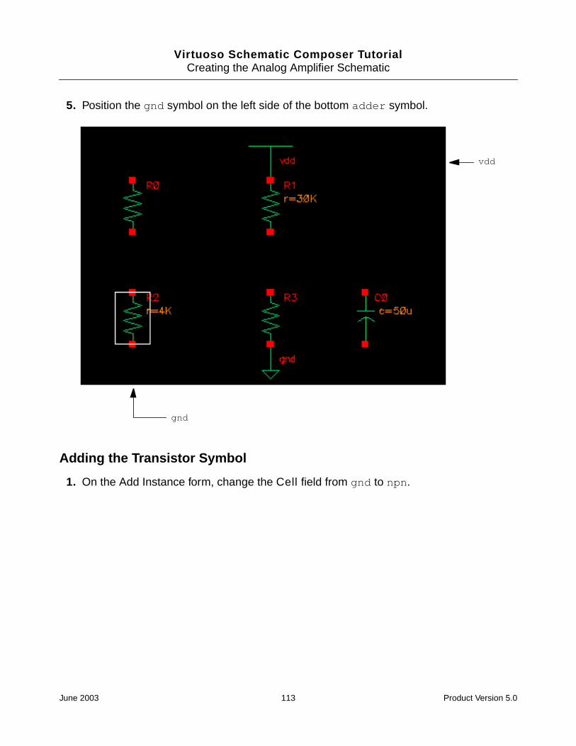
Virtuoso Schematic Composer TutorialCreating the Analog Amplifier Schematic
5. Position the gnd symbol on the left side of the bottom adder symbol.
Adding the Transistor Symbol
1. On the Add Instance form, change the Cell field from gnd to npn.
vdd
gnd
June 2003 113 Product Version 5.0

Virtuoso Schematic Composer TutorialCreating the Analog Amplifier Schematic
The form updates to show the instance parameters for the transistor.
June 2003 114 Product Version 5.0

Virtuoso Schematic Composer TutorialCreating the Analog Amplifier Schematic
2. Position the transistor with the emitter pin on the top pin of R3. Click to place thetransistor.
Adding the I/O Pins
1. On the Add Instance form, change the Library field from analogLib to basic.
2. In the Cell field, replace gnd with ipin.
3. Position the input pin on the left side of the schematic.
4. In the Cell field, replace ipin with opin.
5. Position the output pin on the right side of the schematic.
npn
June 2003 115 Product Version 5.0

Virtuoso Schematic Composer TutorialCreating the Analog Amplifier Schematic
6. Press Esc to cancel the Add – Instance command.
Aligning the Symbols
Using dynamic editing, you can use the mouse to select and move objects in a schematicwithout selecting a command first.
1. Put the pointer on the vdd symbol of R1 and click.
2. Simultaneously, press the Shift key and click over the power symbol of R1.
June 2003 116 Product Version 5.0

Virtuoso Schematic Composer TutorialCreating the Analog Amplifier Schematic
A single highlight box appears around both symbols of R1.
June 2003 117 Product Version 5.0

Virtuoso Schematic Composer TutorialCreating the Analog Amplifier Schematic
3. Click and drag the pointer down and to the R3 transistor until the bottom pin of R1 is overthe transistor collector pin of R3, then release.
Wiring the Schematic
You can wire without using the Wire (thin) command. Dynamic editing allows you to use themouse to wire the schematic from pin to pin.
1. To route a thin wire with the mouse, position the pointer exactly on top of the starting pin.
The pin becomes highlighted and a small square appears on the pin. Be careful not toselect a label or an instance. If you accidently tear off a label or move an instance,choose Edit – Undo.
2. Click and drag the pointer to all destination pins as shown in the figure below.
June 2003 118 Product Version 5.0

Virtuoso Schematic Composer TutorialCreating the Analog Amplifier Schematic
A wire-routing line appears. A diamond appears on the starting pin, while the smallsquare follows the pointer.
3. Wire the instances together until your schematic looks as follows:
When you try to draw a line to a point where a resistor and the power or ground symbolare connected pin to pin, you might get a dashed line in a different color rather than anormal, solid wire. This dashed line is a flight line. Flight lines instead of wires appear indesigns because the wire router would have to violate a routing rule to make aconnection.
4. If you get any flight lines while wiring the schematic, delete the flight lines, pull theinstances apart so that wires appear between them, and complete the wiring.
Cleaning Up the Schematic
1. Choose Check – Rules Setup.
2. Click Defaults.
3. Click on the Check and Save icon.
The CIW reports no errors.
4. Change the generic I/O pin labels.
❑ To label the I/O pins in and out, click on the Properties icon.
June 2003 119 Product Version 5.0

Virtuoso Schematic Composer TutorialCreating the Analog Amplifier Schematic
The Edit Object Properties form appears.
❑ Select the output pin label opin.
There are no fields on the form that you can change.
Caution
Do not use generic I/O pins. You do not want to finish your design with thegeneric pin labels ipin and opin. Always use Add – Pin to add pins to aschematic.
❑ Delete both I/O pins.
❑ Choose Add – Pin and place a new input pin in and a new output pin out from thebasic library. Remember to change Direction to output before placing the out pin.
❑ Press the F3 function key to bring back the Edit Object Properties form.
❑ Select the out pin.
The Edit Object Properties form fields for the out pin are different from the fields forthe opin pin. You can edit the name and you have choices regarding direction,display, and usage.
❑ Click Cancel.
5. Choose Check and Save to save the schematic with the new I/O pins.
June 2003 120 Product Version 5.0

Virtuoso Schematic Composer TutorialCreating the Analog Amplifier Schematic
In the next section, you enter CDF data for the transistor.
Adding CDF Data
Every device in the amp schematic has a unique value that you gave it except for thetransistor. You used the Add Instance and Edit Properties commands to change theproperties of the capacitor and resistors. In this section, you use the CDF editor to addproperties to the transistor Q0.
1. Click on the Properties icon.
The Edit Object Properties form appears.
2. Click on the transistor in the amp schematic.
The Edit Object Properties form has a CDF Parameter field for the Collector-emittervoltage, but there is no entry for the Beta forward CDF parameter. You must use theCDF editor to create the Beta forward parameter and add it to this form.
3. In the CIW, start the CDF editor by choosing Tools – CDF – Edit.
June 2003 121 Product Version 5.0

Virtuoso Schematic Composer TutorialCreating the Analog Amplifier Schematic
The Edit Component CDF form appears.
4. In the Library Name field, type analogLib.
5. In the Cell Name field, type npn.
Leave CDF Selection set to Cell and CDF Type set to Effective.
The Edit Component CDF form expands to display information for the npn cell.
6. In the Component Parameters section, click Add.
June 2003 122 Product Version 5.0

Virtuoso Schematic Composer TutorialCreating the Analog Amplifier Schematic
The Add CDF Parameter form appears.
7. Set Add After Parameter to Vce.
8. Set parseAsNumber to yes.
9. In the name field, type Bf.
10. In the prompt field, type Beta forward.
11. In the display field, type t.
12. In the editable field, type t.
13. Click OK.
June 2003 123 Product Version 5.0

Virtuoso Schematic Composer TutorialCreating the Analog Amplifier Schematic
The Bf parameter is added to the list of CDF parameters on the Edit Component CDFform.
14. Click OK on the Edit Component CDF form.
15. On the amp schematic, select the transistor and edit its properties.
The Beta forward field should now appear on the Edit Object Properties form as a userproperty.
16. In the Beta forward field, type 40.
17. In the Collector-emitter voltage field, type 0.7.
18. Click OK.
19. Choose Check and Save to save the schematic one last time.
In the next section, you will create a symbol for the amp schematic.
June 2003 124 Product Version 5.0

Virtuoso Schematic Composer TutorialCreating the Analog Amplifier Schematic
Creating a Symbol from a Schematic
You now have a complete, checked and saved schematic cellview for the cell amp. To useamp as an element in other designs, you now create a symbol cellview for amp.
1. Choose Design – Create Cellview – From Cellview.
The Cellview From Cellview form appears.
June 2003 125 Product Version 5.0

Virtuoso Schematic Composer TutorialCreating the Analog Amplifier Schematic
The form shows entries for the active design. Library Name should be tutorial, CellName should be amp, and From View Name should be schematic. Make sure that ToView Name is symbol.
2. Click OK.
The Symbol Generation Options form appears. All the fields in the Symbol Generationform should already have the correct entries: tutorial for Library Name, amp for CellName, symbol for View Name, in for Left Pins, out for Right Pins.
3. Click OK on the Symbol Generation Options form.
The CIW displays
Symbol (amp symbol) generated and saved in library:tutorial.Completed generating design in library “tutorial” as “amp”
“symbol”.Adding CDF information . . .
Adding base cell CDF parameter information . . .Adding base cell CDF simulation information . . .
The symbol editor window appears, displaying the amp symbol generated by theschematic composer software.
The automatically generated symbol is functional, with an input pin and an output pin, butit is a simple rectangle. The standard symbol for an amplifier is a triangle, with the outputat its apex.
Use the symbol editor to replace the rectangle with a triangle pointing towards the outputpin.
June 2003 126 Product Version 5.0
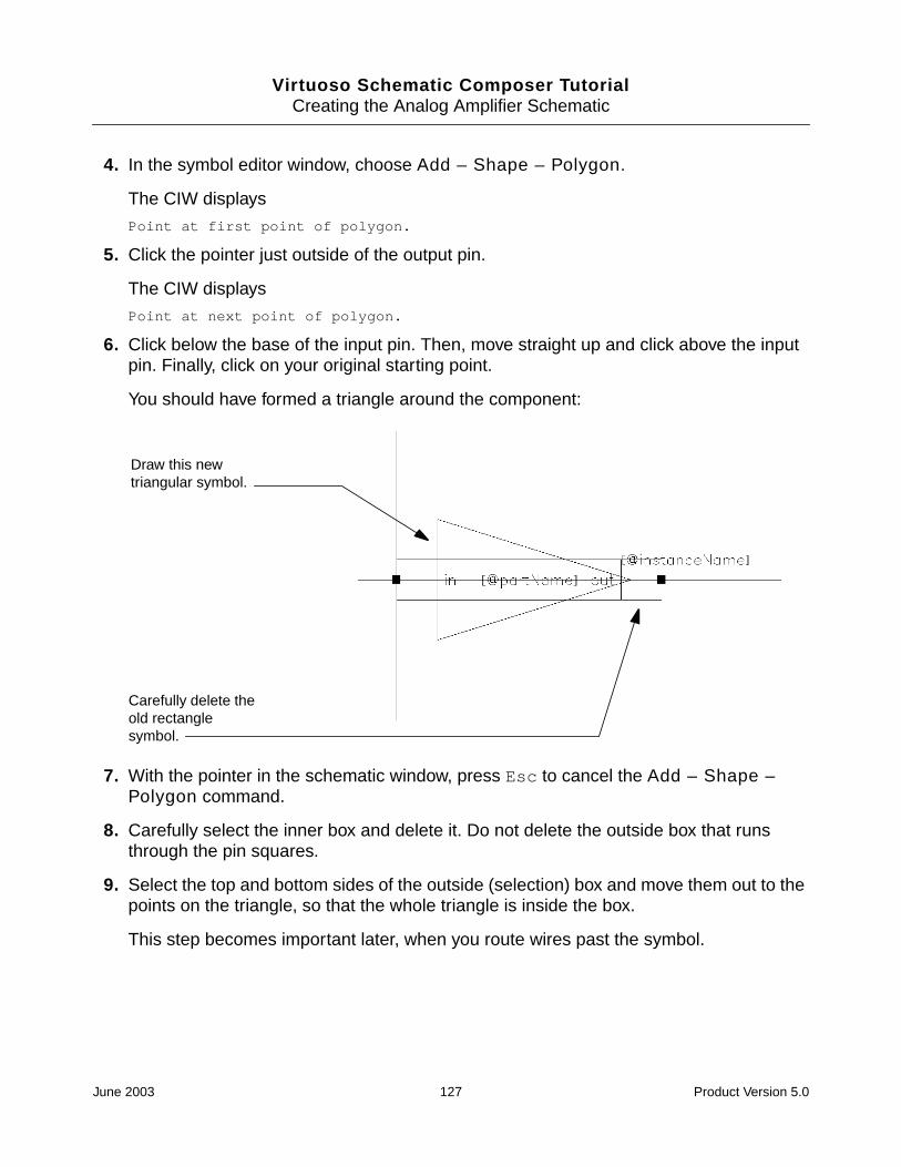
Virtuoso Schematic Composer TutorialCreating the Analog Amplifier Schematic
4. In the symbol editor window, choose Add – Shape – Polygon.
The CIW displays
Point at first point of polygon.
5. Click the pointer just outside of the output pin.
The CIW displays
Point at next point of polygon.
6. Click below the base of the input pin. Then, move straight up and click above the inputpin. Finally, click on your original starting point.
You should have formed a triangle around the component:
7. With the pointer in the schematic window, press Esc to cancel the Add – Shape –Polygon command.
8. Carefully select the inner box and delete it. Do not delete the outside box that runsthrough the pin squares.
9. Select the top and bottom sides of the outside (selection) box and move them out to thepoints on the triangle, so that the whole triangle is inside the box.
This step becomes important later, when you route wires past the symbol.
Draw this newtriangular symbol.
Carefully delete theold rectanglesymbol.
June 2003 127 Product Version 5.0

Virtuoso Schematic Composer TutorialCreating the Analog Amplifier Schematic
The final result should look like this:
10. Check and save the symbol using Design – Check and Save.
If you look at the amp cell in the tutorial library, you can see that it has a schematiccellview and a symbol cellview.
11. Close the symbol editor using Window – Close.
12. If you have not already done so, choose Window – Close to close the schematic editorwith the amp schematic.
You have completed a discrete analog amplifier design, with its own symbol, and with theinstance parameters that you specified.
Stretch the outsideselection box until itincludes the newsymbol.
June 2003 128 Product Version 5.0

Virtuoso Schematic Composer Tutorial
7Preparing the top_level Schematic forSimulation
This chapter describes how to complete the top-level design used in this tutorial. After youhave performed all the steps, you can simulate the operation of the design. Every part usedin the top-level schematic includes a verilog cellview, so you can simulate the design withVerilog® software.
To finish the top-level schematic, you must
■ Add the one’s complement module
■ Complete the wiring and checking of the top level
The following sections describe how to complete these tasks.
Adding the ones_comp Circuit
At the end of the tutorial, you did not do any work on the ones_comp block. There is nothingunder that symbol, so you need to fill in the missing function in that part of the design.
1. Open the top-level design.
2. Choose Design – Descend Edit.
3. Select the ones_comp symbol.
To create the one’s complement symbol, you need to use a two-input XOR gate. TheTTL_tutor library does not have one, but you can find it in the sample library, under thename xor2. Besides I/O pins, this is the only part you need for this circuit.
Assume that the signal INV is the signal bit. Use exclusive-or (XOR) for the INV signalwith each input data bit to produce the circuit output.
June 2003 129 Product Version 5.0

Virtuoso Schematic Composer TutorialPreparing the top_level Schematic for Simulation
Your circuit should look like this:
4. Choose Check – Rules Setup, set the form to its default settings, and run Check andSave. Fix any reported problems.
Be sure that
❑ The I/O pin names match the names on the ones_comp symbol
❑ You label every wire
❑ You remove bus stubs
5. When the ones_comp symbol successfully passes the Check program, close thedesign, move up to the top level, and finish the design at that level.
Finishing the top_level Schematic
If you run Check and Save on the top_level schematic using the default rules, the systemgives you many errors and warnings about floating wires, buses, and pins. Most of thesenotices are caused by the open pins on the ALU. In this section, you finish the wiring of thisschematic.
1. Remove all bus stubs, as you did in the accum cell.
June 2003 130 Product Version 5.0

Virtuoso Schematic Composer TutorialPreparing the top_level Schematic for Simulation
Select the end of each bus and delete the portion of the bus that projects past the lastwire.
2. Wire the CLK signal to the CP input on the ALU.
3. Wire the Cn and OE input pins on the ALU to a ground symbol.
At this point, you might check a databook to decide how you want to wire the rest of thepins for the 2901 part. You can safely wire the remaining input pins to ground, but thesimulation results might not be interesting. Setting all of the instruction input pins toground (0) programs the Add command.
4. Wire all other input pins on the ALU to ground.
Some of the ALU input pins are on the right side of the symbol.
5. Run Check and Save with the default rules, but set floating output pins to ignored.Fix any reported problems.
The finished top_level schematic should look like this:
Now you can simulate this design.
June 2003 131 Product Version 5.0

Virtuoso Schematic Composer TutorialPreparing the top_level Schematic for Simulation
June 2003 132 Product Version 5.0

Virtuoso Schematic Composer Tutorial
ASolving Problems
This appendix describes how to solve problems that you might encounter as you use thistutorial.
Problem Solution
You need to undo acommand.
Press u on the keyboard, choose the Edit – Undo command, orclick on the Undo icon.
Undo does not undo window commands such as Zoom In or Fit.
You need to cancel acommand.
Press Esc with the pointer on the schematic window or click theCancel button on the command form.
You zoomed in on thewrong part of theschematic.
Press f on the keyboard to redisplay the entire schematic and thenzoom in again.
The softwareperforms anunexpectedcommand.
Undo the command. Then, check the prompt line for a commandprompt. You might need to cancel the previous command form.
No form opens whenyou choose Add –Instance.
Click on the Command Options icon.
June 2003 133 Product Version 5.0
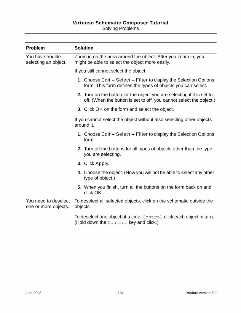
Virtuoso Schematic Composer TutorialSolving Problems
You have troubleselecting an object.
Zoom in on the area around the object. After you zoom in, youmight be able to select the object more easily.
If you still cannot select the object,
1. Choose Edit – Select – Filter to display the Selection Optionsform. This form defines the types of objects you can select.
2. Turn on the button for the object you are selecting if it is set tooff. (When the button is set to off, you cannot select the object.)
3. Click OK on the form and select the object.
If you cannot select the object without also selecting other objectsaround it,
1. Choose Edit – Select – Filter to display the Selection Optionsform.
2. Turn off the buttons for all types of objects other than the typeyou are selecting.
3. Click Apply.
4. Choose the object. (Now you will not be able to select any othertype of object.)
5. When you finish, turn all the buttons on the form back on andclick OK.
You need to deselectone or more objects.
To deselect all selected objects, click on the schematic outside theobjects.
To deselect one object at a time, Control-click each object in turn.(Hold down the Control key and click.)
Problem Solution
June 2003 134 Product Version 5.0

Virtuoso Schematic Composer TutorialSolving Problems
You need to deleteone or more objects.
To delete one object,
1. Click on the object to select it.
2. Press the Delete key.
To delete multiple objects,
1. Choose the objects by either
❑ Dragging a box around the objects
❑ Clicking on the first object to select it and then Shift-clickon additional objects to select them
2. Press the Delete key.
You can also activate the Delete command by pressing Delete orclicking on the Delete icon. While Delete is active, you will deleteeach object you click on. Cancel Delete by pressing Esc (or theCancel button on the Delete form).
You cannot select acommand froma pop-up menu.
You must click the middle mouse button—not the left mousebutton—to select a command from a pop-up menu.
You cannot closea pop-up menu.
Move the pointer off the menu (move it anywhere on the schematicother than on the menu) and click the middle mouse button.
You pick up and movean object when youare trying to select anarea or group ofobjects.
Release the mouse button and click on the Undo icon.
You cannot move anobject.
Press M to activate the Move command. Then follow the prompts inthe prompt line.
You need to stretchan object.
Press m to activate the Stretch command. Then follow the promptsin the prompt line.
You need to movemultiple objects.
Select the objects, press M to activate the Move command, andfollow the prompts in the prompt line.
You need to redisplaya form that you hidwith the Hide button.
With the pointer on the schematic window, press F3, or double-clickthe middle mouse button, or click on the Command Options icon.
Problem Solution
June 2003 135 Product Version 5.0

Virtuoso Schematic Composer TutorialSolving Problems
One of your nets isnot connected.
You can delete the net and create it again, or you can stretch thenet. Press m to activate the Stretch command. Then follow theprompts in the prompt line.
You cannot undo aselected object; thatis, an object outlinedin white.
Undo does not undo a selection. To deselect an object, click on theobject.
Problem Solution
June 2003 136 Product Version 5.0