vistvistvista 20 uka 20 uka 20 uk...
TRANSCRIPT

i
VISTVISTVISTVISTVISTA 20 UKA 20 UKA 20 UKA 20 UKA 20 UKENGINEER’SENGINEER’SENGINEER’SENGINEER’SENGINEER’S
MANUMANUMANUMANUMANUALALALALAL
www.PDF-Zoo.comwww.PDF-Zoo.com

iiwww.PDF-Zoo.comwww.PDF-Zoo.com
iii
ContentsSECTION 1: WIRING AND SAFETY INFORMATION ................ 1General ............................................................................................................... 1Siting ................................................................................................................... 1Fixing .................................................................................................................. 1Ventilation ........................................................................................................... 1Cabling ................................................................................................................ 1Mains Supply Connections ................................................................................. 2Cable Type .......................................................................................................... 3Fuses .................................................................................................................. 3Equipment Electrical Rating ................................................................................ 3Batteries .............................................................................................................. 3
SECTION 2: INSTALLING THE VISTA 20 ................................. 5Fixing the Cabinet ...................................................................... 5Installing The Remote Keypad .................................................. 6Zone Wiring ................................................................................ 7Programmable Output Triggers................................................ 8Wiring an Exit Terminate Button (Push-to-Set) ...................... 8External Bell Connections ........................................................ 9Summary of Main PCB Connections ...................................... 10Telephone Line Installation ..................................................... 12Wiring ................................................................................................................ 12REN .................................................................................................................. 12Approval ............................................................................................................ 13
SECTION 3: OPTIONAL MODULES ........................................ 154208-2 Expander Module ......................................................... 15Addressing ........................................................................................................ 15DIP Switches 5-8 .............................................................................................. 16Connections ...................................................................................................... 16Zone Wiring ....................................................................................................... 17Outputs ............................................................................................................. 17Status LEDs ...................................................................................................... 174204 Relay Module ................................................................... 18DIP Switch Settings .......................................................................................... 18Panel Connections ............................................................................................ 19Relay Connections ............................................................................................ 194110SM Speaker Module ......................................................... 20
www.PDF-Zoo.comwww.PDF-Zoo.com
iv
SECTION 4: PROGRAMMING THE VISTA 20 ......................... 21General ...................................................................................... 21Entering / Exiting Program Mode ...................................................................... 21Programming Format ........................................................................................ 21Defaults ............................................................................................................. 21Software Version ............................................................................................... 21Programming Fields ................................................................ 22Entry/Exit ........................................................................................................... 22Output Options .................................................................................................. 22Field *89 programming (Expander Module Addressing) .................................................... 24Engineer ............................................................................................................ 26User Access Rights (Codes) ............................................................................. 26Zone Programming Options .............................................................................. 27Zone Responses ................................................................................................................ 27Zone Options .................................................................................................... 28Communication ................................................................................................. 30Downloading ..................................................................................................... 32Alpha-Numeric Keypad - Text Programming .................................................... 33Zone Descriptors ................................................................................................................ 33Custom Words .................................................................................................................... 33Library ............................................................................................................... 34Zone Response Definitions............................................................................... 35Output Type Definitions .................................................................................... 38
SECTION 5: OPERATING THE SYSTEM ................................ 43Setting and Unsetting the System.......................................... 43Full Setting the System ..................................................................................... 43Part Setting the System .................................................................................... 43Unsetting the System ........................................................................................ 43Area Setting ...................................................................................................... 43Setting the System with a Mains Fail or a Line Fail .......................................... 43Resetting After an Alarm ......................................................... 44Bypassing Zones ..................................................................... 44Programming User Codes ....................................................... 45Panic Alarm .............................................................................. 45Fire Alarm ................................................................................. 45Duress ....................................................................................... 46Chime ........................................................................................ 46Testing the system .................................................................. 46Setting the Time and Date ....................................................... 46Viewing the Event Log ............................................................. 47Printing the Event Log ............................................................. 47Troubleshooting ....................................................................... 48
www.PDF-Zoo.comwww.PDF-Zoo.com

v
APPENDIX A: SPECIFICATIONS ............................................. 51Control Panel .................................................................................................... 516139 Full Text Keypad ...................................................................................... 516128UK Fixed Text Keypad .............................................................................. 514208 - 2 Expander Module ............................................................................... 524204 Relay Module ........................................................................................... 52
ADEMCO LIMITED WARRANTY.............................................. 53
www.PDF-Zoo.comwww.PDF-Zoo.com

viwww.PDF-Zoo.comwww.PDF-Zoo.com

1
SECTION 1: WIRING ANDSAFETY INFORMATION
GeneralIt is essential that this product is installed correctly, in particular with respect to apersons safety and connection to the mains electricity supply.
This product is not suitable for installation, maintenance or connection by the user;installation and maintenance must be carried out by a competent, qualified installer,for example, BS5750 or NACOSS approved.
It is a condition of the product’s approval that the installer complies with the follow-ing:
SitingThe control panel must be sited indoors in a secure area where it cannot be readilyinterfered with. The location must have adequate ventilation, ample light and easyaccess for servicing and maintenance. It is not suitable for siting externally or inharsh environments where it could be subject to high humidity, extremes of tem-perature, chemical atmospheres, high dust levels, or in a position where it may besubject to dripping or splashing by water or other fluids.
FixingThe control must be securely fixed to a vertical, smooth, solid surface which is partof the fabric of the building. The position chosen must allow the cabinet door to beremoved and allow unhindered access for installation and maintenance.
VentilationWhile the control panel has been designed so that no part reaches an unsafe tempera-ture it is important that adequate ventilation is provided around the cabinet. Heat-radiating equipment or sources of heat should therefore not be positioned close tothe cabinet.
CablingThe product has high voltage barriers between the mains supply (excessive voltage),the alarm wiring terminals (separated extra low voltage) and the telephone line ter-minals (telecom network voltage). It is essential that these barriers are maintained inthe way the cables enter the cabinet, are routed inside the cabinet and are routedexternally.
Knockouts, rear entry points and a trunking point are provided for cable entries;additional holes must not be cut in the enclosure. Where necessary, the cable must beprotected at the entry point by the use of grommets. The cables external to the cabi-net must be either firmly affixed to the fabric of the building using suitable clips orsaddles or mechanically protected in conduit or trunking. Alarm system cables must
www.PDF-Zoo.comwww.PDF-Zoo.com

2
not be allowed to loop inside the cabinet – they must be neatly trimmed. It must notbe possible to put strain on the wiring within the control cabinet by pulling on cablesexternal to the cabinet.
Knockouts or the trunking entry point must only be removed if cables are to enter thecabinet at that point. The hole must be covered by the trunking or conduit or bymeans of a blanking grommet.
It must not be possible to push a finger or similar size object or instrument into anyhole or cable entry point.
Mains Supply ConnectionsNote: This apparatus must be earthed.The connection to the a.c. mains supply must be made by a competent, qualifiedperson, e.g. NICEIC approved, in accordance with the current IEE and local supplyregulations.
The earth impedance of the mains input earth must be verified.
A means of isolation from the mains supply must be provided within 2 metres of thecontrol. This is normally a switched fused spur fitted with a 3 A fuse.
Where a flexible cable is connected to the control panel having cores coloured green/yellow, brown and blue, it is important to connect the wires according to the follow-ing code:
Green/yellow: Earth – connect to terminal marked EBlue: Neutral – connect to terminal N
Brown: Live – connect to terminal L
Where a non-flexible cable is connected to the control having cores coloured red,black, and a green/yellow sleeve covering the earthing conductor, it is important toconnect the wires according to the following code:
Green/yellow: Earth – connect to terminal marked EBlack: Neutral – connect to terminal N
Red: Live – connect to terminal L
The insulation of each conductor must be prepared and connected so that no part ofthe bare conductor is visible or protruding outside the terminal block. In the case ofstandard conductors, all the strands should be twisted together and firmly clamped inthe terminal. Each of the wires must be cut to a length such that if the cable slips outof the cable clamp and is strained, the live conductor will become taut before theconductor that is connected to the protective earth terminal. The outer covering insu-lation must be clamped under the cable clamp provided. It is important that this cableenters the control panel enclosure through the mains entry hole provided, is notlooped within the control panel enclosure and does not run close to other systemcables inside or external to the enclosure.
The cover of the control panel enclosure must not be opened before isolating themains supply. The green Power LED indicates the presence of a.c. mains supply.The cover must be securely fitted in normal use.
www.PDF-Zoo.comwww.PDF-Zoo.com

3
Cable TypeThe conductors of the mains supply cable must have a minimum cross-sectionalarea of 0.75 mm and the insulating material on each conductor must be a minimumof 0.4 mm thick Polyvinyl Chloride (PVC). Flexible cables must conform to therequirements of BS6500 and IEC Publication 227. Non–flexible electrical installa-tion cables must conform to BS6004 and the earth continuity conductor must becovered with a green/yellow sleeve where it leaves the outer sheath.
FusesThe mains fuse within the cabinet is rated at 2A.
The mains supply must be disconnected before opening the cabinet and changingthe fuse. Replace mains fuse with the same type and rating, that is:
Rating: 2A anti-surge (T).Construction: Glass or ceramic (sand filled) cartridge.Dimensions: 25 mm length, 5 mm diameter.
Conformance: BS EN 60127-2 and IEC127-2.
Equipment Electrical RatingThe control equipment is designed to operate on a UK mains supply of 230 Volts a.c.at a frequency of 50 Hz (230 V +10% – 6%, as stated in the IEE publication Com-mentary on BS7671:1992 Requirements for Electrical Installations). It is not suit-able for other types of supply. The maximum current consumption in normal use is80 mA.
BatteriesThe battery used with the control panel must be a 12 V sealed lead-acid rechargeablebattery of up to 7.2 Amp-hour capacity. The battery must be positioned on the bat-tery shelf. The battery leads must be connected to the battery observing the polarityand not allowed to hang near the mains terminal block .
www.PDF-Zoo.comwww.PDF-Zoo.com

4www.PDF-Zoo.comwww.PDF-Zoo.com
5
SECTION 2: INSTALLING THEVISTA 20
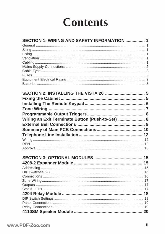
Fixing the CabinetThe enclosure base should be fixed to the mounting surface as follows:
1. Remove the enclosure lid by unscrewing the two fixing screws, sliding thelid upwards past the bottom lip and easing it away from the base.
2. Mark the position of the two mounting holes and keyhole slot on the mountingsurface.
Figure 2.1 Enclosure Layout
3. Position the control panel enclosure on the mounting surface using the keyholeslot in the enclosure base.
4. Bring the cabling into the enclosure via the appropriate cable entry points.The entry points for the a.c. mains and telephone cables are marked in Figure
Cable entry points
Keyhole slot
Knock-outs (on underside)
Mainsentrypoint
LEN
Mounting holes
Fuseterminalblock
Telephoneentrypoint
Zone terminals
Outputtriggers
Telephone line
Vista 20 Printed Circuit Board
Bell tamper
Transformer
Mains fuse
Knock-out (top)
www.PDF-Zoo.comwww.PDF-Zoo.com
6
2.1 Enclosure Layout. Other cabling can be brought in via the four cableentry points on the back-plane or through the knock-outs on the undersideand topside of the enclosure.
5. Secure the enclosure base firmly in place using the two mounting holes, 1.5”x No. 8 screws are recommended. It is strongly recommended that toggle orbutterfly fixings are used if the mouting surface is a cavity wall.
Installing The Remote KeypadA maximum of four remote keypads can be connected to the system. Any of thefollowing keypads can be used:
• 6128UK fixed text • 6128IR fixed text • 6139 full text
Mounting the KeypadCare should be taken when selecting the mounting location and height of the keypad.The keypads should not be mounted directly under a light source and should beslightly below eye level for optimum viewing.
1. Remove the back case by pressing down the two snaps on the keypads upperedge while carefully pulling the two halves of the case apart.
2. Route the wiring from the control panel through the opening in the back ofthe case.
3. Attach the back case to the mounting surface.4. If using the 6139 keypad, plug the supplied flying lead connector into the
keypad PCB socket. If using the 6128 keypad, wire the four cores into the 4way terminal block on the back of the keypad.
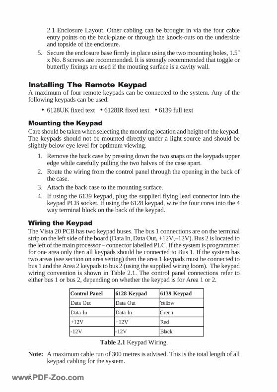
Wiring the KeypadThe Vista 20 PCB has two keypad buses. The bus 1 connections are on the terminalstrip on the left side of the board (Data In, Data Out, +12V,–12V). Bus 2 is located tothe left of the main processor – connector labelled PLC. If the system is programmedfor one area only then all keypads should be connected to Bus 1. If the system hastwo areas (see section on area setting) then the area 1 keypads must be connected tobus 1 and the Area 2 keypads to bus 2 (using the supplied wiring loom). The keypadwiring convention is shown in Table 2.1. The control panel connections refer toeither bus 1 or bus 2, depending on whether the keypad is for Area 1 or 2.
lenaPlortnoC dapyeK8216 dapyeK9316
tuOataD tuOataD wolleY
nIataD nIataD neerG
V21+ V21+ deR
V21- V21- kcalB
Note: A maximum cable run of 300 metres is advised. This is the total length of allkeypad cabling for the system.
Table 2.1 Keypad Wiring.
www.PDF-Zoo.comwww.PDF-Zoo.com

7
Zone WiringThe standard system supports up to 8 wired zones. These zones are double-pole,normally closed alarm and tamper loops. An additional tamper zone (zone 9) isincluded on the main board for the external bell tamper. The system can also beexpanded to 24 zones - for details see 4208-2 Expansion Module. See Figure 2.2Zone Wiring for zone 5 and 6 connections.
Figure 2.3 Normally Open Zone
Tamper Alarm
Zone 6
13 14 15 16
Normally OpenDevice
Figure 2.2 Zone Wiring
The zones can also be configured for normally open devices. This is done by leavingthe alarm and tamper links fitted across the zone terminals and wiring the normallyopen contacts across the pair of links. This is shown in Figure 2.3 Normally OpenZone.
Tamper TamperAlarm Alarm
Zone 6 Zone 5
13 14 15 16 17 18 19 20
www.PDF-Zoo.comwww.PDF-Zoo.com
8
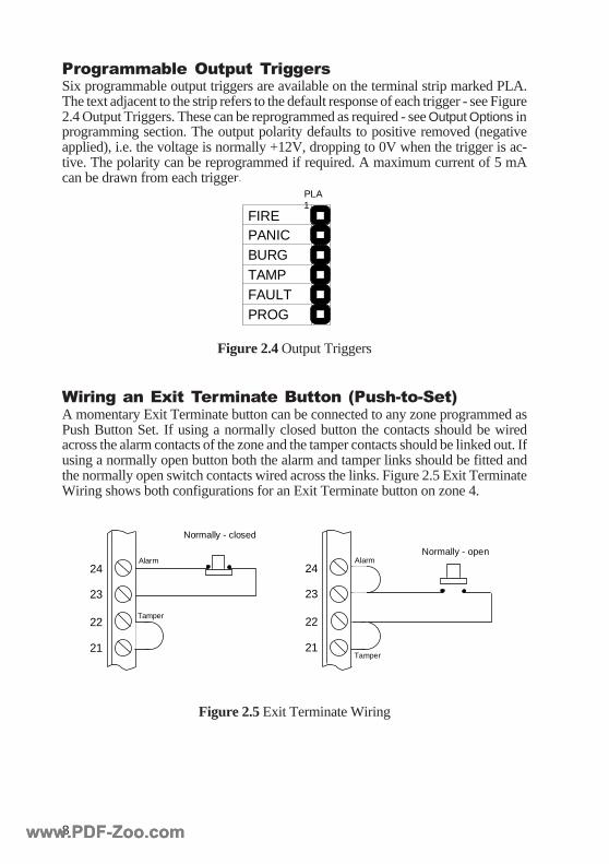
Programmable Output TriggersSix programmable output triggers are available on the terminal strip marked PLA.The text adjacent to the strip refers to the default response of each trigger - see Figure2.4 Output Triggers. These can be reprogrammed as required - see Output Options inprogramming section. The output polarity defaults to positive removed (negativeapplied), i.e. the voltage is normally +12V, dropping to 0V when the trigger is ac-tive. The polarity can be reprogrammed if required. A maximum current of 5 mAcan be drawn from each trigger.
Figure 2.4 Output Triggers
Wiring an Exit Terminate Button (Push-to-Set)A momentary Exit Terminate button can be connected to any zone programmed asPush Button Set. If using a normally closed button the contacts should be wiredacross the alarm contacts of the zone and the tamper contacts should be linked out. Ifusing a normally open button both the alarm and tamper links should be fitted andthe normally open switch contacts wired across the links. Figure 2.5 Exit TerminateWiring shows both configurations for an Exit Terminate button on zone 4.
PLA
PROGFAULTTAMPBURGPANICFIRE
1
Figure 2.5 Exit Terminate Wiring
Normally - closed
Alarm
Tamper
24
21
22
23
Alarm
Tamper
24
21
22
23
Normally - open
www.PDF-Zoo.comwww.PDF-Zoo.com
9
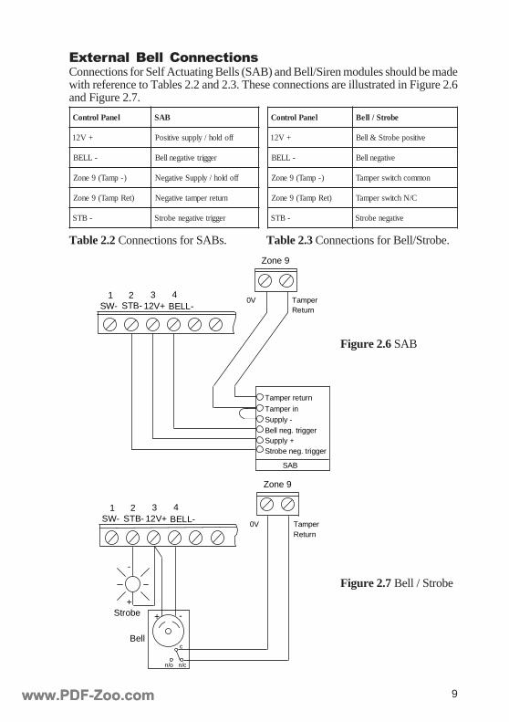
Table 2.2 Connections for SABs. Table 2.3 Connections for Bell/Strobe.
lenaPlortnoC BAS
+V21 ffodloh/ylppusevitisoP
-LLEB reggirtevitagenlleB
)-pmaT(9enoZ ffodloh/ylppuSevitageN
)teRpmaT(9enoZ nruterrepmatevitageN
-BTS reggirtevitagenebortS
Zone 9
SW-2
12V+3 41
STB- BELL-TamperReturn
0V
Bell neg. trigger
Strobe neg. triggerSupply +
Tamper return
Supply -Tamper in
SAB
Figure 2.6 SAB
SW-2
12V+3 41
STB- BELL-
Bell
Strobe + -
Zone 9
TamperReturn
0V
+
-
c
n/cn/o
Figure 2.7 Bell / Strobe
External Bell ConnectionsConnections for Self Actuating Bells (SAB) and Bell/Siren modules should be madewith reference to Tables 2.2 and 2.3. These connections are illustrated in Figure 2.6and Figure 2.7.
lenaPlortnoC ebortS/lleB
+V21 evitisopebortS&lleB
-LLEB evitagenlleB
)-pmaT(9enoZ nommochctiwsrepmaT
)teRpmaT(9enoZ C/NhctiwsrepmaT
-BTS evitagenebortS
www.PDF-Zoo.comwww.PDF-Zoo.com

10
Summary of Main PCB Connections
Battery / Ground TerminalsGND Equipment Ground Terminal - connection must be intact at all times.
BATT- Battery Negative - Connect to the -ve (black) terminal of the battery.
BATT+ Battery Positive - Connect to the +ve (red) terminal of the battery.
Output Triggers (default allocation)
1. Fire trigger2. Panic trigger3. Alarm (Intruder) trigger4. Tamper trigger - responds to tamper alarms when the system is unset.
When full set, a tamper alarm activates the Alarm output trigger.5. Fault trigger - responds to low battery, mains fail, memory checksum
failure and watchdog reset.6. Programme trigger - activates when programming mode is entered.
Power / Keypad TerminalsAC These two terminals connect to the 13 V a.c. output of the mains
transformer. They are not for direct connection to the mains supply.
Data Out Connects to the Data Out (yellow) terminal of the Area 1 keypads andthe Data Out connections on expansion modules or relay outputmodules, if fitted.
Data In Connect to the Data In (green) terminal of the Area 1 keypads and theData In connections on any expansion module or relay outputmodule, if fitted.
12 AUX Auxiliary 12 V supply - two pairs of terminals are available forconnection of remote keypads and auxiliary fused devices.
Note: Area 2 keypads should be connected to the terminal strip marked “Area 2Keypads” in Figure 2.8 PCB Connections. A four wire loom is provided forthis purpose. The same wiring convention as Area 1 should be followed.
Bell / Zone / SW- terminals
1. Switched Negative Supply - This output can be programmed as:(a) Negative supply for smoke detectors or other latching deviceswhich require the interruption of the supply to reset. The output isnormally 0 V switching to +12 V for 6 seconds on the second entry ofCode + Off after an alarm condition. The output can also be activatedat any point in the unset state by pressing the Ö and 1 keys together.(b) Printer data output for a serial printer.(c) Sounder output.
2. Strobe negative - for connection with external strobe negative.3. Positive bell / strobe supply - common positive, limited by fuse to 1
Amp maximum (labelled F3 in Figure 2.8 PCB Connections).
www.PDF-Zoo.comwww.PDF-Zoo.com
11
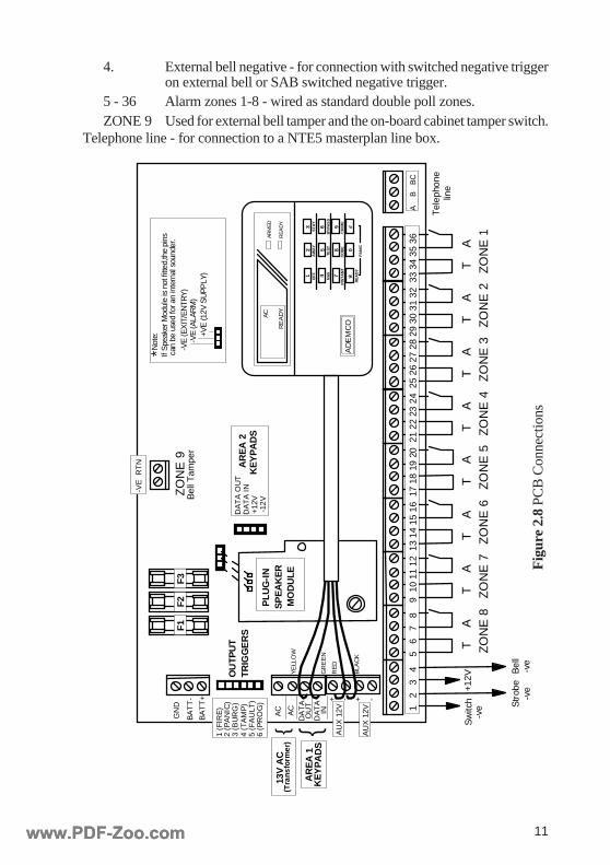
4. External bell negative - for connection with switched negative triggeron external bell or SAB switched negative trigger.
5 - 36 Alarm zones 1-8 - wired as standard double poll zones.ZONE 9 Used for external bell tamper and the on-board cabinet tamper switch.
Telephone line - for connection to a NTE5 masterplan line box.
OU
TPU
TTR
IGG
ER
S4
(TA
MP
)
1 (F
IRE
)2
(PA
NIC
)
6 (P
RO
G)
5 (F
AU
LT)
3 (B
UR
G)
GN
D
BA
TT
-
BA
TT
+
AC AC
DA
TA
OU
TD
AT
AIN
+ -- +
YE
LLO
W
GR
EE
N
RE
D
BLA
CK
-VE
RT
N
ZO
NE
9B
ell T
ampe
r
T
AZ
ON
E 8
T
AZ
ON
E 7
T
AZ
ON
E 6
T
AZ
ON
E 5
T
AZ
ON
E 4
T
AZ
ON
E 3
T
AZ
ON
E 2
T
AZ
ON
E 1
Sw
itch
-ve
+12V
Bel
l-v
eS
trob
e-v
e
A
B
BC
Tel
epho
nelin
e
DA
TA
OU
TD
AT
A I
N+
12V
-12
V
AR
EA
2K
EY
PA
DS
F1F3
F2 PLU
G-I
NS
PE
AK
ER
MO
DU
LE
1 2
3
4
5
6 7
8
9
10
11 1
2 1
3 14
15
16 1
7 18
19
20 2
1 22
23
24 2
5 26
27
28 2
9 30
31
32 3
3 34
35
36
RE
AD
Y
AC
AR
ME
D
RE
AD
Y
#963
0852
4 71 ÖOF
FA
WA
YS
TA
Y
MAX
TES
TBY
PA
SS
INS
TA
NT
CO
DE
CH
IME
RE
AD
YP
AN
IC
AD
EM
CO
AU
X 1
2V
AR
EA
1K
EY
PA
DS
13V
AC
(Tra
nsfo
rmer
)
AU
X 1
2V
-VE
(EX
IT/E
NTR
Y)
-VE
(ALA
RM
)+V
E (1
2V S
UPP
LY)
ÖN
ote:
If S
peak
er M
odul
e is
not
fitte
d,th
e pi
nsca
n be
use
d fo
r an
inte
rnal
sou
nder
.
Fig
ure
2.8
PC
B C
onne
ctio
ns
www.PDF-Zoo.comwww.PDF-Zoo.com

12
Telephone Line InstallationBefore connecting the telephone line, ensure that the system has been correctly in-stalled as detailed herein and that the cable routing has been carried out as advised.Remove the connection to the AC supply by switching off at the external fuse spuror the circuit isolator. Remove the control cabinet cover, as outlined in Fixing theCabinet, and ensure that the mains indicator on the main PCB is off. Do not attemptto continue if the mains supply is still present within the control. Disconnect thebattery leads and remove the battery from the cabinet.
WiringA connection is provided on the Vista 20 for an ex-directory standard PSTN tel-ephone line. This connection must be made to an NTE5 master socket (line box). Itis strongly recommended that no telephones or related equipment should be con-nected to the same telephone line. The connection to the telephone line terminalsmust only be made by an approved installer. The wiring must be mechanically pro-tected external to the cabinet and must enter via the telephone entry point shown inFigure 2.1 Enclosure Layout. It must not enter the cabinet by any other point.
The unit is not suitable for connection to a pay-phone or shared service line and it isnot suited for use with PABX or other types of external exchange. It is intended tointerface directly with PSTN lines with loop disconnect (pulse dial) or multi-fre-quency (DTMF) signals.
The unit has been approved for the use of the following facilities: modem; loopdisconnect signalling; multi-frequency signalling; auto calling; auto answering. Anyother usage will invalidate the approval of the apparatus and it will cease to conformwith the standards against which the approval was granted.
The telephone cable must conform to the requirements of BT specification CW1308.This cable uses a single strand conductor of 0.5mm CSA and the wires are configuredin twisted pairs. A suitable cable from RS components is code 368-413 (2 pair ca-ble). Alarm or any other type of cable must not be used. Communications must onlybe made to an NTE5 master socket (line box) user port or an extension correctlyconnected to the master socket. Where terminals use insulated displacement tech-niques, a special terminal tool must be used.
Instructions and wiring call code given in OFTEL wiring code Part 1 must be fol-lowed (see Figure 2.9 Telephone Line Connections) i.e.
Terminal A - White wire with blue rings - NTE5 terminal 5.
Terminal B - Blue wire with white rings - NTE5 terminal 2.
Terminal BC - Orange wire with white rings - NTE5 terminal 3.
RENThe Ringer Equivalence Number (REN) is a guide to the maximum number of itemsof apparatus which may be connected simultaneously to the telephone line. The totalREN is obtained by adding up the REN values of each item of equipment connectedto the exclusive line. Any BT approved instrument is assumed to have a REN of 1.0unless it is otherwise marked.
www.PDF-Zoo.comwww.PDF-Zoo.com
13
The REN of the Vista 20 is 0.5. If the panel is connected to a telephone line withadditional telephone apparatus connected then the total REN of the additional appa-ratus must not exceed 2.5. The Vista 20 is intended to be connected to an exclusiveline and it is strongly recommended that no other apparatus should is connected.
WarningThe approval of this equipment for communication to the PSTN is invalidated if theapparatus is subject to any modification in any material way not authorised by BABTor if it is used with or connected to any of the following:
1. Internal software that has not been formerly accepted by BABT.2. External control software or external control apparatus which causes the
operation of this equipment or associated call set up equipment to contravenethe requirements of the BABT standards. (BABT/SITS/82/005S/D).
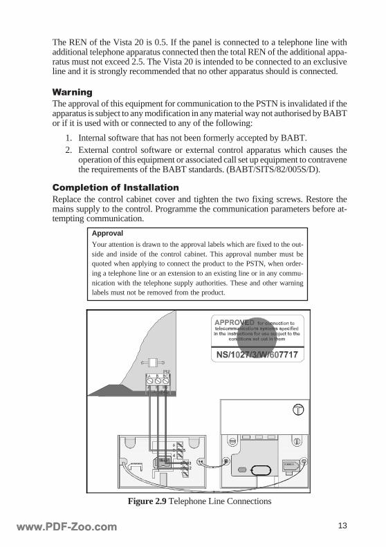
Completion of InstallationReplace the control cabinet cover and tighten the two fixing screws. Restore themains supply to the control. Programme the communication parameters before at-tempting communication.
Figure 2.9 Telephone Line Connections
Approval
Your attention is drawn to the approval labels which are fixed to the out-side and inside of the control cabinet. This approval number must bequoted when applying to connect the product to the PSTN, when order-ing a telephone line or an extension to an existing line or in any commu-nication with the telephone supply authorities. These and other warninglabels must not be removed from the product.
www.PDF-Zoo.comwww.PDF-Zoo.com

14www.PDF-Zoo.comwww.PDF-Zoo.com
15
SECTION 3: OPTIONALMODULES
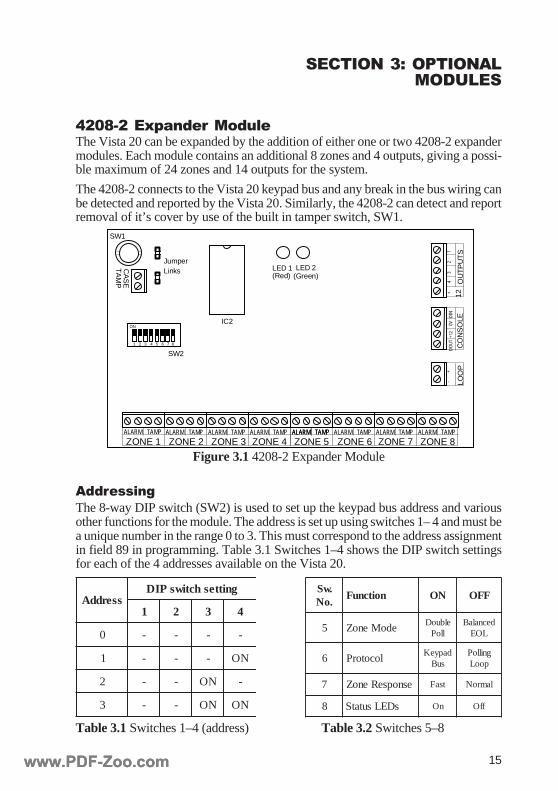
4208-2 Expander ModuleThe Vista 20 can be expanded by the addition of either one or two 4208-2 expandermodules. Each module contains an additional 8 zones and 4 outputs, giving a possi-ble maximum of 24 zones and 14 outputs for the system.
The 4208-2 connects to the Vista 20 keypad bus and any break in the bus wiring canbe detected and reported by the Vista 20. Similarly, the 4208-2 can detect and reportremoval of it’s cover by use of the built in tamper switch, SW1.
Figure 3.1 4208-2 Expander Module
AddressingThe 8-way DIP switch (SW2) is used to set up the keypad bus address and variousother functions for the module. The address is set up using switches 1– 4 and must bea unique number in the range 0 to 3. This must correspond to the address assignmentin field 89 in programming. Table 3.1 Switches 1–4 shows the DIP switch settingsfor each of the 4 addresses available on the Vista 20.
Table 3.1 Switches 1–4 (address) Table 3.2 Switches 5–8
sserddAgnitteshctiwsPID
1 2 3 4
0 - - - -
1 - - - NO
2 - - NO -
3 - - NO NO
.wS
.oNnoitcnuF NO FFO
5 edoMenoZ elbuoDlloP
decnalaBLOE
6 locotorP dapyeKsuB
gnilloPpooL
7 esnopseRenoZ tsaF lamroN
8 sDELsutatS nO ffO
CA
SE
TA
MP
ON
ZONE 2 ZONE 3 ZONE 4 ZONE 5 ZONE 6 ZONE 7 ZONE 8ZONE 1
12O
UT
PU
TS1
+2
34
CO
NS
OLED
IN0V
+12
DO
UT
LOO
P
-+
LED 1(Red)
LED 2(Green)
IC2
ALARM TAMPALARM TAMPALARM TAMPALARM TAMPALARM TAMPALARM TAMPALARM TAMPALARM TAMPALARM TAMP
JumperLinks
SW1
SW21 2 3 4 5 6 7 8
www.PDF-Zoo.comwww.PDF-Zoo.com
16
DIP Switches 5-8Table 3.2 Switches 5–8 lists the module functions controlled by switches 5 to 8.These functions are described below.
Zone Mode (Switch 5)Switch 5 changes the zone mode between double poll and balanced end-of-line (EOL).If set to double-poll the zones operate as normally-closed, alarm and tamper loops. Ifset to balanced EOL, series and end-of line resistors must be used. Refer to Figure3.2 Balanced EOL Configuration.
Protocol (Switch 6)Switch 6 should always be set to ON to enable connection with the Vista 20 keypadbus. Connections should be made to the terminals marked CONSOLE on the 4208-2. The LOOP terminals are not used on the 4208-2.
(Another version of the expander (4208-3) will be able to work with the Vista 4140and 4170 making use of the LOOP connections.)
Zone Response (Switch 7)Switch 7 changes the zone response time from Normal to Fast Response.
Status LEDs (Switch 8)Switch 8 determines whether the status LEDs (LED 1 and LED2) operate or not. Thefunction of the status LEDs is described in Table 3.4 Status LEDs.
Note: When the 4208-2 is configured onto the Vista 20, any DIP switch changeswill not take effect until the system power is removed then reconnected.
ConnectionsThe following procedure should be followed when connecting the 4208-2 expanderto the Vista 20:
1. Remove power (mains and battery) from the Vista 20.2. Referring to Table 3.3 4208-2 Connections, connect the four terminals on the
4208-2 CONSOLE terminal strip to the Vista 20 keypad bus using therecommended wiring colours. Either keypad bus 1 or 2 can be used regardlessof the area that the zones are assigned to. Keypads, 4208-2 and 4204 modules(see 4204 Relay Module) can be connected in daisy chain or star.
2-8024 02atsiV ruoloC
V0 -V21xuA kcalB
V21 +V21xuA deR
niD nIataD neerG
tuoD tuOataD wolleY
Table 3.3 4208-2 Connections
www.PDF-Zoo.comwww.PDF-Zoo.com
17
3. Ensure that the two PCB jumper links shown in Figure 3.1 4208-2 ExpanderModule are fitted. These should always be fitted on the 4208-2 expander.
4. If a lid tamper is required, no connection should be made to the CASE TAMPterminals. Any lid tamper condition will then be reported along the keypadbus. If the CASE TAMP terminals are linked out, the lid tamper is disabled.
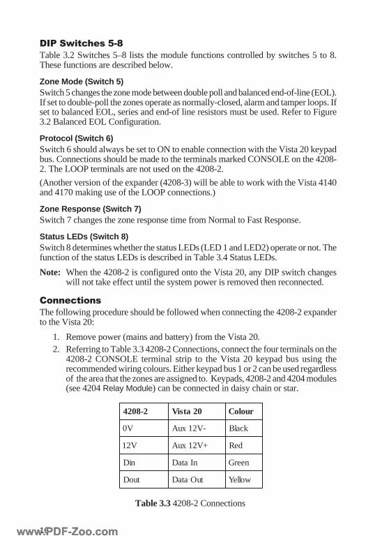
Zone WiringDIP switch 5 selects the wiring configuration for the alarm loop of all eight zones.This can either be closed circuit convention or balanced end of line (EOL) configu-ration. For the balanced EOL configuration the tamper loop must always be closedcircuit. This configuration is shown in Figure 3.2 Balanced EOL Configuration.
Note: A maximum of 10 contacts can be fitted on each loop for balanced EOL.TAMPALARM
1kΩ 1kΩ1kΩ
NC tamper loop
OutputsThe 4208-2 has four programmable output triggers which operate as positive re-moved (normally 12 V switching to 0 V when active). The outputs are open-collec-tor and can provide a maximum current of 100 mA. A common +12 V connection isavailable on the same terminal block for use with the outputs. See Figure 3.1 4208-2 Expander Module for the location of the outputs on the PCB.
Note: Although it is possible to add two 4208-2 expanders and two 4204 relaymodules to the system, no more than eight outputs can be used. These can beeight triggers via 4208-2 modules, eight relays via 4204 modules or fourtriggers and four relays from both module types.
Status LEDsThe status of the 4208-2 module is displayed on LED1 (red) and LED2 (green) ifswitch 8 is set to ON. Table 3.4 Status LEDs details the meaning of each state.
)deR(1DEL )neerG(2DEL gninaeM
FFO FFO teston8hctiwsPID/rewoPoN
NO FFO detcetedatadoN
GNIHSALF FFO ylnosdapyekrofdetcetedataD
FFO GNIHSALFro2-8024rehtorofdetcetedataD
4024
NO NO 2-8024sihtrofdetcetedataD
Table 3.4 Status LEDs
Figure 3.2 Balanced EOL Configuration
www.PDF-Zoo.comwww.PDF-Zoo.com
18
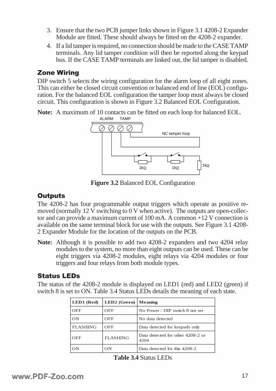
4204 Relay ModuleThe 4204 relay module adds one to four dry, Single Pole Double Throw (SPDT)relay outputs to the Vista 20. A maximum of two modules can be connected to theVista 20 keypad bus. The relay outputs can be used as an alternative to using the4208-2 outputs.
The 4204 has a built in tamper switch which allows it to detect the removal of it’scover and report this to the control panel. Communication to the 4204 is supervisedso that it cannot be removed from the data bus without detection by the control.
-erddAss
gnitteshctiwsPID
2 3 4 5
0 NO NO NO NO
1 - NO NO NO
2 NO - NO NO
3 - - NO NO
Figure 3.3 4204 Relay Module
DIP Switch SettingsThe address for the 4204 should be set using positions 2-5 of the 5 way DIP switch.The address must be a unique number in the range 0 to 4. Refer to Table 3.5 forsettings. DIP switch 1 enables/disables the lid tamper. If set to OFF the tamper isenabled.
Table 3.5 4204 DIP Switch Setting
ON1
23
45
13 16151413 161514
1211
109
58
76
14
32RELAY
1
RELAY2
RELAY3
C
NO
NC
C
NO
NC
C
NO
NC
C
NO
NCTB1
TB2
COVER TAMPER (REED) SWITCH
4 PIN CONSOLE PLUG
YEL
RED
GRN
BLK0V
DATA OUT
DATA IN
+12V
0V
DATA OUT
DATA IN
+12V
RELAY4
TYPICAL(SHOWN OFF)DIP SWITCH
EITHER OR BOTHCAN BE USED
www.PDF-Zoo.comwww.PDF-Zoo.com
19
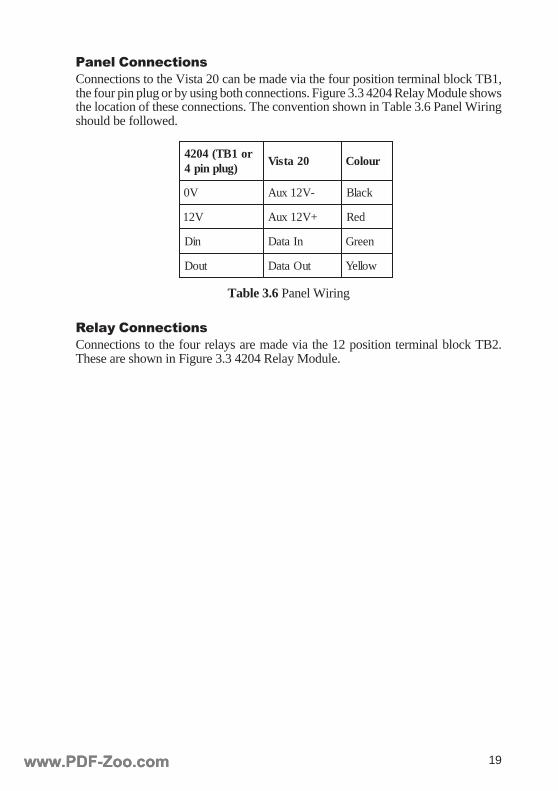
Panel ConnectionsConnections to the Vista 20 can be made via the four position terminal block TB1,the four pin plug or by using both connections. Figure 3.3 4204 Relay Module showsthe location of these connections. The convention shown in Table 3.6 Panel Wiringshould be followed.
ro1BT(4024)gulpnip4
02atsiV ruoloC
V0 -V21xuA kcalB
V21 +V21xuA deR
niD nIataD neerG
tuoD tuOataD wolleY
Table 3.6 Panel Wiring
Relay ConnectionsConnections to the four relays are made via the 12 position terminal block TB2.These are shown in Figure 3.3 4204 Relay Module.
www.PDF-Zoo.comwww.PDF-Zoo.com
20
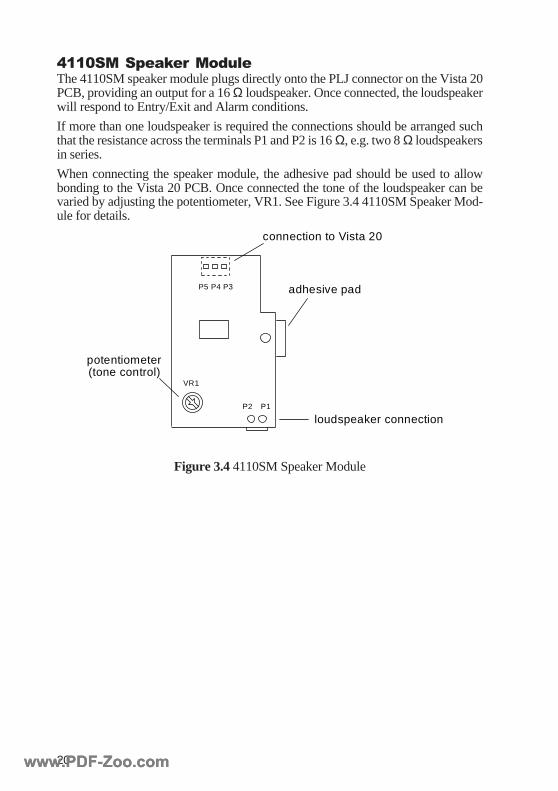
4110SM Speaker ModuleThe 4110SM speaker module plugs directly onto the PLJ connector on the Vista 20PCB, providing an output for a 16 Ω loudspeaker. Once connected, the loudspeakerwill respond to Entry/Exit and Alarm conditions.
If more than one loudspeaker is required the connections should be arranged suchthat the resistance across the terminals P1 and P2 is 16 Ω, e.g. two 8 Ω loudspeakersin series.
When connecting the speaker module, the adhesive pad should be used to allowbonding to the Vista 20 PCB. Once connected the tone of the loudspeaker can bevaried by adjusting the potentiometer, VR1. See Figure 3.4 4110SM Speaker Mod-ule for details.
adhesive pad
potentiometer(tone control)
loudspeaker connection
connection to Vista 20
VR1
P1P2
P3P5 P4
Figure 3.4 4110SM Speaker Module
www.PDF-Zoo.comwww.PDF-Zoo.com

21
SECTION 4: PROGRAMMINGTHE VISTA 20
GeneralWhen access has been made to program mode, the system parameters can be changedfrom the factory default settings. The default values for each of the parameters areshown in brackets above each programming field. If no changes are made to thesedefaults the system will operate as an audible only alarm.
Entering / Exiting Program ModeTo enter engineer mode: Enter engineer code + 8 + 0 + 0. If the engineer code hasbeen lost press the Ö + # keys together within 30 seconds of powering up the sys-tem. (No programming will be lost other than date and time).
To exit engineer mode: Enter Ö99. The default engineer code is 4115. It is stronglyrecommended that this code is changed by the engineer.
Note: Programming mode can only be entered from an Area 1 keypad.
Programming FormatIn engineer mode, the system programming can be modified using the Ö key orviewed using the # key:
To programme a field: Enter Ö + field number + field entry (in engineer mode).
e.g. to change the engineer code to 1111 enter Ö00 then 1111, where 00 is the fieldnumber for the engineer code. Two beeps indicate entry confirmed.
To view contents of a field: Enter # + field number (in engineer mode).
Each programming field on the following pages is shown preceded by Ö/#. Thisindicates that the Ö key should be pressed to change the field or the # key should bepressed to view the contents of the field. The Ö key also acts as an enter key whenentering less than the maximum number of digits for a particular field.
DefaultsTo return the programming back to factory defaults: Enter Ö97, wait five sec-onds then enter Ö97 again.
Note: This will clear all previous programming.
To default the master code (user 01) : Enter Ö95, wait 5 seconds then enter Ö95again. The default master code is 1234.
Software VersionTo view which version of software the control panel is using, enter #92 in engineermode.
www.PDF-Zoo.comwww.PDF-Zoo.com
22
Programming Fields
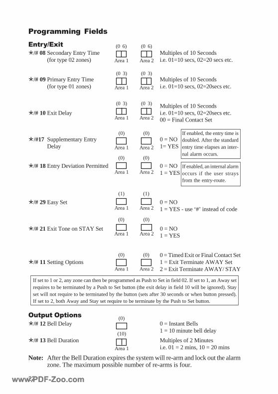
Entry/ExitÖ/# 08Secondary Entry Time Multiples of 10 Seconds
(for type 02 zones) i.e. 01=10 secs, 02=20 secs etc.
Ö/# 09Primary Entry Time Multiples of 10 Seconds(for type 01 zones) i.e. 01=10 secs, 02=20secs etc.
Multiples of 10 SecondsÖ/# 10Exit Delay i.e. 01=10 secs, 02=20secs etc.
00 = Final Contact Set
Ö/#17 Supplementary Entry 0 = NODelay 1= YES
Ö/# 18Entry Deviation Permitted 0 = NO1 = YES
Ö/# 29Easy Set 0 = NO1 = YES - use ‘#’ instead of code
Ö/# 21Exit Tone on STAY Set 0 = NO1 = YES
0 = Timed Exit or Final Contact SetÖ/# 11Setting Options 1 = Exit Terminate AWAY Set
2 = Exit Terminate AWAY/ STAY
Output OptionsÖ/# 12Bell Delay 0 = Instant Bells
1 = 10 minute bell delay
Ö/# 13Bell Duration Multiples of 2 Minutesi.e. 01 = 2 mins, 10 = 20 mins
Note: After the Bell Duration expires the system will re-arm and lock out the alarmzone. The maximum possible number of re-arms is four.
Area 1 Area 2
(0 3) (0 3)
Area 1 Area 2
(0 6) (0 6)
Area 1 Area 2
(0 3) (0 3)
Area 1 Area 2
(0) (0)
Area 1 Area 2
(0) (0)
Area 1 Area 2
(1) (1)
Area 1 Area 2
(0) (0)
Area 1 Area 2
(0) (0)
If enabled, the entry time isdoubled. After the standardentry time elapses an inter-nal alarm occurs.
If enabled, an internal alarmoccurs if the user straysfrom the entry-route.
If set to 1 or 2, any zone can then be programmed as Push to Set in field 02. If set to 1, an Away setrequires to be terminated by a Push to Set button (the exit delay in field 10 will be ignored). Stayset will not require to be terminated by the button (sets after 30 seconds or when button pressed).If set to 2, both Away and Stay set require to be terminate by the Push to Set button.
Area 1
(10)
(0)
www.PDF-Zoo.comwww.PDF-Zoo.com
23
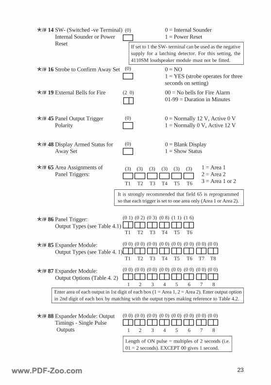
Ö/# 14SW- (Switched -ve Terminal) 0 = Internal SounderInternal Sounder or Power 1 = Power ResetReset
Ö/# 16Strobe to Confirm Away Set 0 = NO1 = YES (strobe operates for threeseconds on setting)
Ö/# 19External Bells for Fire 00 = No bells for Fire Alarm01-99 = Duration in Minutes
Ö/# 45Panel Output Trigger 0 = Normally 12 V, Active 0 VPolarity 1 = Normally 0 V, Active 12 V
Ö/# 48Display Armed Status for 0 = Blank DisplayAway Set 1 = Show Status
Ö/# 65Area Assignments of 1 = Area 1Panel Triggers: 2 = Area 2
3 = Area 1 or 2
Ö/# 86Panel Trigger:Output Types (see Table 4.1)
Ö/# 85Expander Module:Output Types (see Table 4. 1)
Ö/# 87Expander Module:Output Options (Table 4. 2)
Ö/# 88Expander Module: OutputTimings - Single Pulse Outputs
(3) (3) (3) (3)(3)(3)
T1 T6T5T4T3T2
(0)
(0)
(0 0) (0 0) (0 0) (0 0)(0 0)(0 0) (0 0)(0 0)
T1 T6T5T4T3T2 T7 T8
1 65432 7 8
(0 0) (0 0) (0 0) (0 0)(0 0)(0 0) (0 0)(0 0)
1 65432 7 8
(0 0) (0 0) (0 0) (0 0)(0 0)(0 0) (0 0)(0 0)
T1 T6T5T4T3T2
(0 1) (0 8) (1 1) (1 6)(0 3)(0 2)
(0)
(0)
(2 0)
Length of ON pulse = multiples of 2 seconds (i.e.01 = 2 seconds). EXCEPT 00 gives 1 second.
Enter area of each output in 1st digit of each box (1 = Area 1, 2 = Area 2). Enter output optionin 2nd digit of each box by matching with the output types making reference to Table 4.2.
If set to 1 the SW- terminal can be used as the negativesupply for a latching detector. For this setting, the4110SM loudspeaker module must not be fitted.
It is strongly recommended that field 65 is reprogrammedso that each trigger is set to one area only (Area 1 or Area 2).
www.PDF-Zoo.comwww.PDF-Zoo.com
24
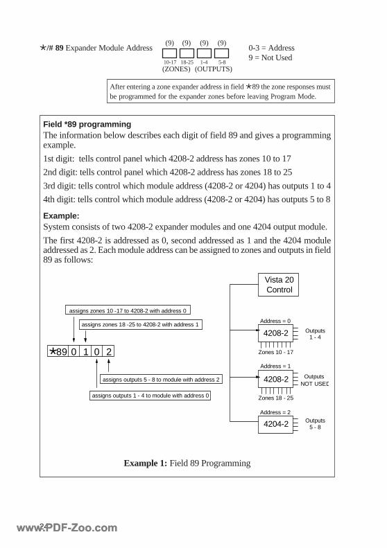
Ö/# 89Expander Module Address 0-3 = Address9 = Not Used
(9) (9)(9)(9)
10-17 18-25 1-4 5-8(ZONES) (OUTPUTS)
After entering a zone expander address in field Ö89 the zone responses mustbe programmed for the expander zones before leaving Program Mode.
Field *89 programmingThe information below describes each digit of field 89 and gives a programmingexample.
1st digit: tells control panel which 4208-2 address has zones 10 to 17
2nd digit: tells control panel which 4208-2 address has zones 18 to 25
3rd digit: tells control which module address (4208-2 or 4204) has outputs 1 to 4
4th digit: tells control which module address (4208-2 or 4204) has outputs 5 to 8
Example:System consists of two 4208-2 expander modules and one 4204 output module.
The first 4208-2 is addressed as 0, second addressed as 1 and the 4204 moduleaddressed as 2. Each module address can be assigned to zones and outputs in field89 as follows:
Vista 20Control
4208-2
4208-2
4204-2
Address = 0
Address = 2
Address = 1
Zones 10 - 17
Zones 18 - 25
Outputs1 - 4
OutputsNOT USED
Outputs5 - 8
assigns zones 10 -17 to 4208-2 with address 0
assigns zones 18 -25 to 4208-2 with address 1
assigns outputs 5 - 8 to module with address 2
assigns outputs 1 - 4 to module with address 0
0 201Ö89
Example 1: Field 89 Programming
www.PDF-Zoo.comwww.PDF-Zoo.com
25
edoCtuptuO
sepyTtuptuOsnoitpO
00 DESUTON –
10 ERIF HCTAL
20 CINAP WOLLOF
30 MRALA HCTAL
40 TESTRAP WOLLOF
50 TES WOLLOF
70 RUOH42 HCTAL
80 REPMAT HCTAL
90 evitisoPHCTALTES )laiceps(HCTAL
11 ELBUORT/TLUAF HCTAL
21 LIAFROTACINUMMOC WOLLOF
31 XUA HCTAL
41 TROBA WOLLOF
51 DEIFIREV HCTAL
61 GORP WOLLOF
71 32EPYTENOZ WOLLOF
91 TLUAFENIL WOLLOF
02 LLEB WOLLOF
edoCtuptuO
sepyTtuptuOsnoitpO
12 EBORTS WOLLOF
22 REDNUOSLANRETNI WOLLOF
32 EDOMTSET WOLLOF
62 YDAER WOLLOF
72DEMRA
NOITAMRIFNOCESLUPELGNIS
82 YRTNE WOLLOF
92 TIXE WOLLOF
03 TIXEROYRTNE WOLLOF
33 YRETTABWOL WOLLOF
43 LIAFSNIAM WOLLOF
53 GODHCTAW HCTAL
63 LIAFYROMEM HCTAL
73 EMIHC ESLUPELGNIS
93 TSETCIDOIREP ESLUPELGNIS
04 0+EDOCRESU ESLUPELGNIS
14 31EDOCRESU ESLUPELGNIS
24DENGISSAEDOCRESU
YLNOREGGIRTSAESLUPELGNIS
dn2tigiD
noitcnuF noitanalpxE
0 hctaLtonsidnasruccotnevetratsehtecnoV0otspordtuptuO
siFFO+edocresu/retsamehtlitnu)V21+ot(teserderetne
2 wolloF tnevetratsswolloftuptuO
3 esluPelgniSelbaTees(noitarudtesafoeslupV0elgnisasevigtuptuO
V21+otserotserneht)3
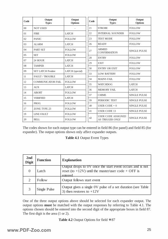
Table 4.1 Output Event Types
One of the three output options above should be selected for each expander output. Theoutput options must be matched with the output responses by referring to Table 4.1. Theoptions chosen should be entered into the second digit of the appropriate boxes in field 87.The first digit is the area (1 or 2).
The codes shown for each output type can be entered in field 86 (for panel) and field 85 (forexpander). The output options shown only affect expander outputs.
Table 4.2 Output Options for field Ö87
www.PDF-Zoo.comwww.PDF-Zoo.com
26
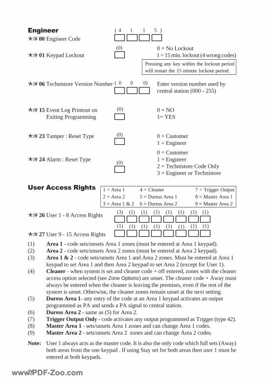
EngineerÖ/# 00Engineer Code
0 = No LockoutÖ/# 01Keypad Lockout 1 = 15 min. lockout (4 wrong codes)
Ö/# 06Technistore Version Number Enter version number used bycentral station (000 - 255)
Ö/# 15Event Log Printout on 0 = NOExiting Programming 1= YES
Ö/# 23Tamper : Reset Type 0 = Customer1 = Engineer
0 = CustomerÖ/# 24Alarm : Reset Type 1 = Engineer
2 = Technistore Code Only3 = Engineer or Technistore
User Access Rights
Ö/# 26User 1 - 8 Access Rights
Ö/# 27User 9 - 15 Access Rights
(1) Area 1 - code sets/unsets Area 1 zones (must be entered at Area 1 keypad).(2) Area 2 - code sets/unsets Area 2 zones (must be entered at Area 2 keypad).(3) Area 1 & 2 - code sets/unsets Area 1 and Area 2 zones. Must be entered at Area 1
keypad to set Area 1 and then Area 2 keypad to set Area 2 (except for User 1).(4) Cleaner - when system is set and cleaner code + off entered, zones with the cleaner
access option selected (see Zone Options) are unset. The cleaner code + Away mustalways be entered when the cleaner is leaving the premises, even if the rest of thesystem is unset. Otherwise, the cleaner zones remain unset at the next setting.
(5) Duress Area 1- any entry of the code at an Area 1 keypad activates an outputprogrammed as PA and sends a PA signal to central station.
(6) Duress Area 2 - same as (5) for Area 2.(7) Trigger Output Only - code activates any output programmed as Trigger (type 42).(8) Master Area 1 - sets/unsets Area 1 zones and can change Area 1 codes.(9) Master Area 2 - sets/unsets Area 2 zones and can change Area 2 codes.
Note: User 1 always acts as the master code. It is also the only code which full sets (Away)both areas from the one keypad . If using Stay set for both areas then user 1 must beentered at both keypads.
( 4 1 1 5 )
( 0 0 0)
(0)
(0)
(0)
1 = Area 1 4 = Cleaner 7 = Trigger Output2 = Area 2 5 = Duress Area 1 8 = Master Area 13 = Area 1 & 2 6 = Duress Area 2 9 = Master Area 2
(0)
Pressing any key within the lockout periodwill restart the 15 minute lockout period.
(1) (1) (1) (1)(1)(1) (1)(1)
(3) (1) (1) (1)(1)(1) (1)(1)
www.PDF-Zoo.comwww.PDF-Zoo.com
27
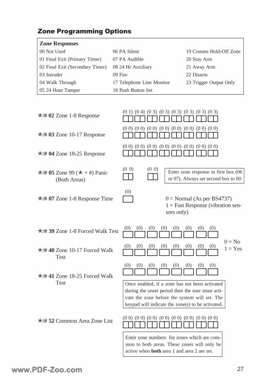
Ö/# 02Zone 1-8 Response
Ö/# 03 Zone 10-17 Response
Ö/# 04Zone 18-25 Response
Ö/# 05Zone 99 (Ö + #) Panic(Both Areas)
Ö/# 07Zone 1-8 Response Time 0 = Normal (As per BS4737)1 = Fast Response (vibration sen-sors only)
Ö/# 39Zone 1-8 Forced Walk Test
Ö/# 40Zone 10-17 Forced WalkTest
Ö/# 41Zone 18-25 Forced WalkTest
Ö/# 52Common Area Zone List
Zone Responses00 Not Used 06 PA Silent 19 Comms Hold-Off Zone
01 Final Exit (Primary Timer) 07 PA Audible 20 Stay Arm
02 Final Exit (Secondary Timer) 08 24 Hr Auxiliary 21 Away Arm
03 Intruder 09 Fire 22 Disarm
04 Walk Through 17 Telephone Line Monitor 23 Trigger Output Only
05 24 Hour Tamper 18 Push Button Set
Zone Programming Options
(0)
(0) (0) (0) (0)(0)(0) (0)(0)
(0) (0) (0) (0)(0)(0) (0)(0)
(0) (0) (0) (0)(0)(0) (0)(0)
(0 0) (0 0) (0 0) (0 0)(0 0)(0 0) (0 0)(0 0)
Enter zone numbers for zones which are com-mon to both areas. These zones will only beactive when both area 1 and area 2 are set.
(0 0) (0 0)
(0 0) (0 0) (0 0) (0 0)(0 0)(0 0) (0 0)(0 0)
(0 1) (0 3) (0 3) (0 3)(0 3)(0 4) (0 3)(0 3)
(0 0) (0 0) (0 0) (0 0)(0 0)(0 0) (0 0)(0 0)
0 = No1 = Yes
Enter zone response in first box (06or 07). Always set second box to 00.
Once enabled, if a zone has not been activatedduring the unset period then the user must acti-vate the zone before the system will set. Thekeypad will indicate the zone(s) to be activated.
www.PDF-Zoo.comwww.PDF-Zoo.com
28
Ö/# 55Zone 3 Options
Ö/# 56 Zone 4 Options
Ö/# 57 Zone 5 Options
Ö/# 58 Zone 6 Options
Ö/# 59 Zone 7 Options
Ö/# 60 Zone 8 Options
Ö/# 69 Zone 10 Options
Ö/# 70 Zone 11 Options
Ö/# 71 Zone 12 Options
Ö/# 72 Zone 13 Options
Ö/# 54 Zone 2 Options
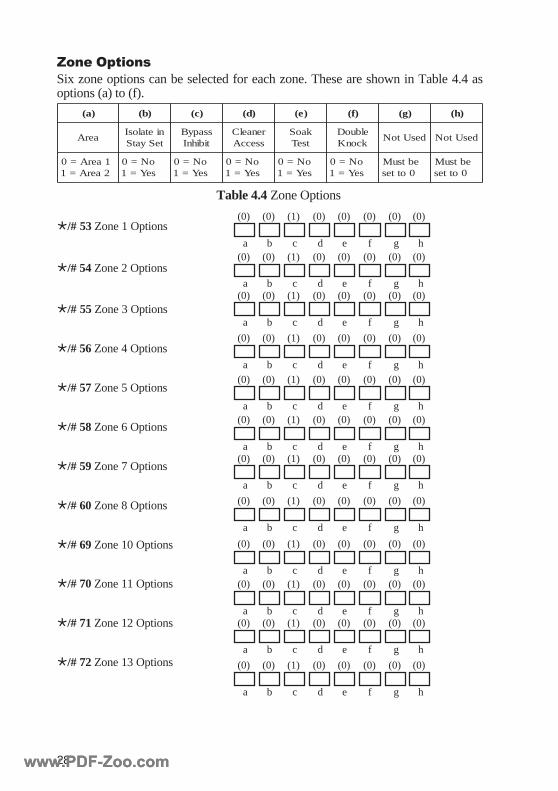
)a( )b( )c( )d( )e( )f( )g( )h(
aerAnietalosIteSyatS
ssapyBtibihnI
renaelCsseccA
kaoStseT
elbuoDkconK
desUtoN desUtoN
1aerA=02aerA=1
oN=0seY=1
oN=0seY=1
oN=0seY=1
oN=0seY=1
oN=0seY=1
ebtsuM0ottes
ebtsuM0ottes
Zone OptionsSix zone options can be selected for each zone. These are shown in Table 4.4 asoptions (a) to (f).
Ö/# 53Zone 1 Options(0) (0) (0) (0)(1)(0) (0)(0)
a b c d e f g h(0) (0) (0) (0)(1)(0) (0)(0)
a b c d e f g h(0) (0) (0) (0)(1)(0) (0)(0)
a b c d e f g h
(0) (0) (0) (0)(1)(0) (0)(0)
a b c d e f g h(0) (0) (0) (0)(1)(0) (0)(0)
a b c d e f g h(0) (0) (0) (0)(1)(0) (0)(0)
a b c d e f g h(0) (0) (0) (0)(1)(0) (0)(0)
a b c d e f g h
(0) (0) (0) (0)(1)(0) (0)(0)
a b c d e f g h
(0) (0) (0) (0)(1)(0) (0)(0)
a b c d e f g h(0) (0) (0) (0)(1)(0) (0)(0)
a b c d e f g h(0) (0) (0) (0)(1)(0) (0)(0)
a b c d e f g h
(0) (0) (0) (0)(1)(0) (0)(0)
a b c d e f g h
Table 4.4 Zone Options
www.PDF-Zoo.comwww.PDF-Zoo.com
29
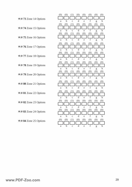
Ö/# 73 Zone 14 Options
Ö/# 74 Zone 15 Options
Ö/# 75 Zone 16 Options
Ö/# 76 Zone 17 Options
Ö/# 77 Zone 18 Options
Ö/# 78 Zone 19 Options
Ö/# 79 Zone 20 Options
Ö/# 80 Zone 21 Options
Ö/# 81 Zone 22 Options
Ö/# 82 Zone 23 Options
Ö/# 83 Zone 24 Options
Ö/# 84 Zone 25 Options (0) (0) (0) (0)(1)(0) (0)(0)
a b c d e f g h
(0) (0) (0) (0)(1)(0) (0)(0)
a b c d e f g h(0) (0) (0) (0)(1)(0) (0)(0)
a b c d e f g h(0) (0) (0) (0)(1)(0) (0)(0)
a b c d e f g h
(0) (0) (0) (0)(1)(0) (0)(0)
a b c d e f g h(0) (0) (0) (0)(1)(0) (0)(0)
a b c d e f g h(0) (0) (0) (0)(1)(0) (0)(0)
a b c d e f g h(0) (0) (0) (0)(1)(0) (0)(0)
a b c d e f g h
(0) (0) (0) (0)(1)(0) (0)(0)
a b c d e f g h(0) (0) (0) (0)(1)(0) (0)(0)
a b c d e f g h(0) (0) (0) (0)(1)(0) (0)(0)
a b c d e f g h(0) (0) (0) (0)(1)(0) (0)(0)
a b c d e f g h
www.PDF-Zoo.comwww.PDF-Zoo.com
30
CommunicationThe Vista 20 has the capability to transmit in one of two formats to a central stationdigital receiver. These formats are:
(1) Ademco high speed (standard UK high speed format).
(2) Ademco contact ID (point ID).
The Vista 20 does not require a pre-programmed PROM since all communicationparameters are programmed from the Vista 20 keypad.
High Speed FormatIn the standard UK high speed format it is usual to assign channels to the alarm typesas follows:
Channel 01 is normally assigned for fire alarm conditions.Channel 02 is normally assigned for PA (panic) alarm conditions.Channel 03 is normally assigned for intruder alarms (burglary).Channel 04 reports open/close signals.
For the Vista 20 additional channels are assigned as follows:
Channel 05 reports daytime tampers.Channel 06 reports trouble conditions.Channel 07 reports an abort code.Channel 08 reports verified alarms.Channel 09 reports low battery and test signals
The channel reporting may be enabled/disabled for each zone. Each zone is assignedto channel 03 by default and only requires changing if a different report or no report-ing of a zone is required. In addition to alarm reports, a restore report may be sent foreach channel. The restore will by default be transmitted after the second entry ofcode + Off after an alarm condition. This can be changed in programming field 50.
Contact ID FormatWhen using contact ID format each event is transmitted as a unique event type (eventcode) instead of sending channel activations. The user or zone number related to theevent is also transmitted along with the message. The data is sent as follows:
AAAA Q EEE GG ZZZ, where:
AAAA = account number.Q = event qualifier, i.e. E = new event, R = restore.EEE = event code.GG = group number (area).ZZZ = zone or user number.
It is advised that each zone is assigned a different channel code to allow more thanone zone transmission for a given set period. Fifteen channels can be used for con-tact ID so it is not possible to put all 24 zones on different channels. It is advised thatzones 01 to 13 are assigned to channels 03 to 15. If more than 13 zones are used thenzones 14 to 24 should be assigned channels 03 to 13. The only exception is for Fire
www.PDF-Zoo.comwww.PDF-Zoo.com
31
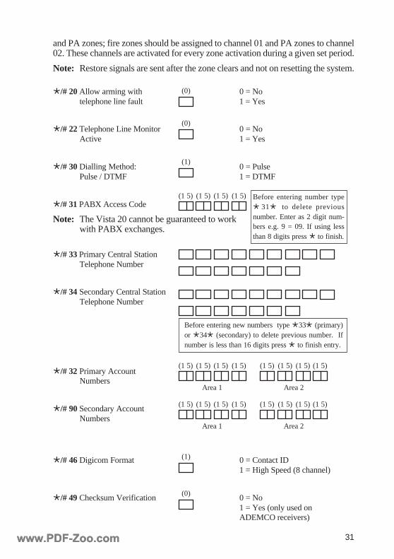
Ö/# 20 Allow arming with 0 = Notelephone line fault 1 = Yes
Ö/# 22 Telephone Line Monitor 0 = NoActive 1 = Yes
Ö/# 30 Dialling Method: 0 = PulsePulse / DTMF 1 = DTMF
Ö/# 31 PABX Access Code
Note: The Vista 20 cannot be guaranteed to workwith PABX exchanges.
Ö/# 33 Primary Central StationTelephone Number
Ö/# 34 Secondary Central StationTelephone Number
Ö/# 32 Primary AccountNumbers
Ö/# 90 Secondary AccountNumbers
Ö/# 46 Digicom Format 0 = Contact ID1 = High Speed (8 channel)
Ö/# 49 Checksum Verification 0 = No1 = Yes (only used onADEMCO receivers)
and PA zones; fire zones should be assigned to channel 01 and PA zones to channel02. These channels are activated for every zone activation during a given set period.
Note: Restore signals are sent after the zone clears and not on resetting the system.
Before entering number typeÖ 31Ö to delete previousnumber. Enter as 2 digit num-bers e.g. 9 = 09. If using lessthan 8 digits press Ö to finish.
Before entering new numbers type Ö33Ö (primary)or Ö34Ö (secondary) to delete previous number. Ifnumber is less than 16 digits press Ö to finish entry.
(0)
(1 5) (1 5)(1 5)(1 5)
(1)
(0)
Area 1
(1 5) (1 5)(1 5)(1 5)
Area 2
(1 5) (1 5) (1 5)(1 5)
Area 1
(1 5) (1 5)(1 5)(1 5)
Area 2
(1 5) (1 5) (1 5)(1 5)
(1)
(0)
www.PDF-Zoo.comwww.PDF-Zoo.com
32
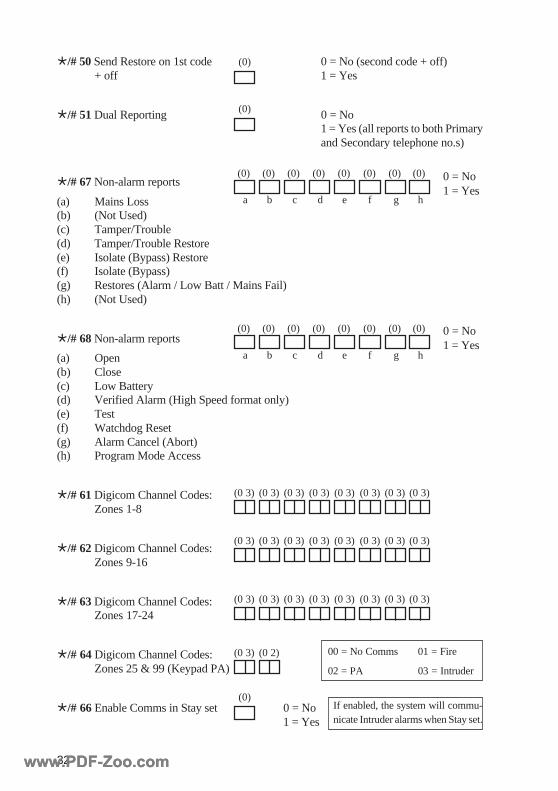
Ö/# 50 Send Restore on 1st code 0 = No (second code + off)+ off 1 = Yes
Ö/# 51 Dual Reporting 0 = No1 = Yes (all reports to both Primaryand Secondary telephone no.s)
Ö/# 67 Non-alarm reports
(a) Mains Loss(b) (Not Used)(c) Tamper/Trouble(d) Tamper/Trouble Restore(e) Isolate (Bypass) Restore(f) Isolate (Bypass)(g) Restores (Alarm / Low Batt / Mains Fail)(h) (Not Used)
Ö/# 68 Non-alarm reports
(a) Open(b) Close(c) Low Battery(d) Verified Alarm (High Speed format only)(e) Test(f) Watchdog Reset(g) Alarm Cancel (Abort)(h) Program Mode Access
Ö/# 61 Digicom Channel Codes:Zones 1-8
Ö/# 62 Digicom Channel Codes:Zones 9-16
Ö/# 63 Digicom Channel Codes:Zones 17-24
Ö/# 64Digicom Channel Codes:Zones 25 & 99 (Keypad PA)
Ö/# 66Enable Comms in Stay set 0 = No1 = Yes
(0)
(0) (0) (0) (0)(0)(0) (0)(0)
a b c d e f g h
(0) (0) (0) (0)(0)(0) (0)(0)
a b c d e f g h
(0 3) (0 3) (0 3) (0 3)(0 3)(0 3) (0 3)(0 3)
(0 3) (0 3) (0 3) (0 3)(0 3)(0 3) (0 3)(0 3)
(0 3) (0 3) (0 3) (0 3)(0 3)(0 3) (0 3)(0 3)
(0 3) (0 2)
0 = No1 = Yes
(0)
0 = No1 = Yes
00 = No Comms
02 = PA
01 = Fire
03 = Intruder
(0)If enabled, the system will commu-nicate Intruder alarms when Stay set.
www.PDF-Zoo.comwww.PDF-Zoo.com
33
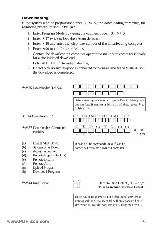
DownloadingIf the system is to be programmed from NEW by the downloading computer, thefollowing procedure should be used:
1. Enter Program Mode by typing the engineer code + 8 + 0 + 0.
2. Enter Ö97 twice to load the system defaults.3. Enter Ö35 and enter the telephone number of the downloading computer.4. Enter Ö99 to exit Program Mode.5. Contact the downloading computer operator to make sure computer is ready
for a site initiated download.6. Enter 4115 + # + 1 to initiate dialling.7. Do not pick up any telephone connected to the same line as the Vista 20 until
the download is completed.
Ö/# 35 Downloader: Tel No.
Ö 36 Downloader ID
Ö/# 37 Downloader: CommandEnables
(a) Dialler Shut Down(b) System Shut Down(c) Access When Set(d) Remote Bypass (Isolate)(e) Remote Disarm(f) Remote Arm(g) Upload Program(h) Download Program
Ö/# 44 Ring Count 00 = No Ring Detect (01-14 rings)15 = Answering Machine Defeat
(1 5) (1 5) (1 5) (1 5)(1 5)(1 5) (1 5)(1 5)
Before entering new number type Ö35Ö to delete previ-ous number. If number is less than 16 digits press Ö tofinish entry.
(1) (1) (1) (1)(1)(1) (1)(1)
a b c d e f g h
If enabled, the commands (a) to (f) can becarried out from the download computer.
(1 2)
Enter no. of rings (01 to 14) before panel answers in-coming call. If set to 15 panel will only pick up line ifdownload PC calls in, hangs up after 2 rings then redials.
0 = No1 = Yes
www.PDF-Zoo.comwww.PDF-Zoo.com

34
Alpha-Numeric Keypad - Text ProgrammingZone descriptors are created by entering words from the built-in library. Alterna-tively an additional 20 ‘custom’ words can be created and used.
Zone DescriptorsTo enter a zone descriptor the following steps should be taken:
1. Once in Program Mode type Ö93 to enter text programming mode.2. From the “Zone Descriptors, Enter Zone” prompt enter the zone number (01
– 25). The display then shows the zone number and the character A.
3. Each key represents several characters (see Figure 4.1 Character Allocation).Select the first character of the word required by pressing the relevant keyuntil this letter appears on the display. For example if the letter R is required,press the 6 key three times. If custom words have already been created, the 0key is used to access them.
4. Once the correct character is displayed, press the Ö key to access the wordlist.
5. Press any number key (0 – 9) to scroll forwards through the word list until therequired word is displayed.
6. Press the Ö key to accept the selection. The display then shows 0A.7. Select the 1st letter of the next word by pressing the relevant key (see Figure
4.1) or press Ö to save word into memory.8. Repeat until the required number of words are displayed (maximum of three).
Note: The ‘#’ key acts as an undo key when programming text.
Figure 4.1 Character Allocation
Custom WordsTo enter a custom word into the library, use the following procedure:
1. In Program Mode, type Ö93 to enter Text Programming Mode.2. From the “Zone Descriptors, Enter Zone” prompt, type 00 to enter Custom
Word Programming Mode.3. Enter the custom word number – between 00 and 19.4. Press the number key which represents the first character of the new word
(see Figure 4.1) until this character is shown on the display.
J K L M N O P Q R
V W XS T U Y Z
A B C D E F G H I
Ö #0
21 3
4 5 6
7 8 9
www.PDF-Zoo.comwww.PDF-Zoo.com

35
5. Press the Ö key to accept the selection.6. Continue entering characters until the word is complete (maximum of 9 letters).7. Press # to enter the word in memory.
Note: After pressing the Ö key to accept a letter, press the Ö again to enter a spaceif required.
Library
A ELSIA D SRETHGUAD H LLAH N HTRON S EFAS W LLAWMRALA KSED TAEH YRESRUN ERUCES ESUOHERAW
EVOCLA ROTCETED ESUOH TXEN ROSNES HSAWTNEMTRAPA GNINID ECIVRES TSEW
AERA YALPSID I NI O ECIFFO DEHS WODNIWOIDUA ROOD DERARFNI NEPO KCOHS ENIW
YRAILIXUA SROOD EDISNI GNINEPO POHS GNIWNWOD ROIRETNI EDISTUO TROHS SSELERIW
B YBAB SRIATSNWOD NOISURTNI SDRAWTUO EDIS KROWKCAB ELBUOD SDRAWNI DAEHREVO ELGNIS SKROW
RAB YAWEVIRD GNIDILSNRAB GURD J YRELLEWEJ P GNITNIAP LLAMS X RETTIMX
TNEMESAB LENAP EKOMSMOORHTAB E TSAE K NEHCTIK CINAP SNOS Y DRAY
YAB CIRTCELE YRTNAP REDNUOSDEB YCNEGREME L GNIDNAL EVISSAP HTUOS Z ENOZ
MOORDEB ECNARTNE EGRAL OITAP SRIATSLLEB YRTNE YRDNUAL RETEMIREP NOITATS TS1,1
DGB TNEMPIUQE TFEL RIP KCOTS DN2,2RELIOB EVITUCEXE LEVEL TNIOP EGAROTS DR3,3MOTTOB TIXE SHL ECILOP EROTS HT4,4
XOB ROIRETXE YRARBIL GNILLOP SEROTS HT5,5KAERB THGIL LOOP GNIMMIWS HT6,6
TSAFKAERB F YROTCAF GNIVIL HCROP HCTIWS HT7,7GNIDLIUB ERULIAF GNIDAOL USP HT8,8
NOTTUB SREHTAF YBBOL REWOP T REPMAT HT9,9ECNEF KCOL EPAT 0
C TENIBAC ERIF TFOL Q DAUQ MOCELETNEETNAC ROOLF POOL OT
RAC LIOF EGNUOL R OIDAR LOOTHSAC REYOF WOL RAER POT
REIHSAC REZEERF REWOL REVIECER EDARTVTCC TNORF NOITPECER RETTIMSNART
GNILIEC M ENIHCAM FRLARTNEC G YRELLAG CITENGAM SHR U ARTLU
TIUCRIC EGARAG REGANAM THGIR PUMOORKAOLC NEDRAG NIAM MOOR REPPU
DESOLC SAG RETSAM FOOR SRIATSPUNOITCELLOC ETAG TAM YTILITU
RETUPMOC LARENEG LACIDEM XTUECNEREFNOC SSALG ENICIDEM
YROTAVRESNOC SDOOG YENOM V TLUAVTCATNOC TSEUG ROTINOM NOITARBIVRETNUOC NUG SREHTOM EGATLOVRODIRROC NOITOM
www.PDF-Zoo.comwww.PDF-Zoo.com
36
00 Not Used 06 PA Silent 19 Comms Hold-Off Zone
01 Final Exit (Primary Timer) 07 PA Audible 20 Stay Arm
02 Final Exit (Secondary Timer) 08 24 Hr Auxiliary 21 Away Arm
03 Intruder 09 Fire 22 Disarm
04 Walk Through 17 Telephone Line Monitor 23 Trigger Output Only
05 24 Hour Tamper 18 Push to Set
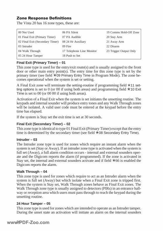
Zone Response DefinitionsThe Vista 20 has 16 zone types, these are:
Final Exit (Primary Timer) – 01This zone type is used for the entry/exit route(s) and is usually assigned to the frontdoor or other main entry point(s). The entry time for this zone type is set by theprimary timer (see field Ö09 Primary Entry Time in Program Mode). The zone be-comes operational when the system is set or setting.
A Final Exit zone will terminate the setting-routine if programming field Ö11 set-ting options is set to 0 (or 00 if using both areas) and programming field Ö10 ExitTime is set to 00 (or 00 00 if using both areas).
Activation of a Final Exit when the system is set initiates the unsetting routine. Thekeypads and internal sounder will produce entry tones and any Walk Through zoneswill be isolated. A valid user code must be entered at the keypad before the entrytime has elapsed.
If the system is Stay set the exit time is set at 30 seconds.
Final Exit (Secondary Timer) – 02This zone type is identical to type 01 Final Exit (Primary Timer) except that the entrytime is determined by the secondary timer (see field Ö08 Secondary Entry Time).
Intruder – 03The Intruder zone type is used for zones which require an instant alarm when thesystem is set (Stay or Away). If an intruder zone type is activated when the system isfull set (Away), a full alarm condition occurs - internal and external sounders oper-ate and the Digicom reports the alarm (if programmed). If the zone is activated inStay set, the internal and external sounders activate and if field Ö66 is enabled theDigicom reports the alarm.
Walk Through – 04This zone type is used for zones which require to act as an Intruder alarm when thesystem is full set (Away) but which isolate when a Final Exit zone is tripped first.When the system is Stay set, Walk Through zones behave as Final Exit zones. TheWalk Through zone type is usually assigned to detectors (PIRs) in an entrance hall-way or reception area which users must pass through to reach the keypad during theunsetting routine.
24 Hour Tamper – 05This zone type is used for zones which are intended to operate as an Intruder tamper.During the unset state an activation will initiate an alarm on the internal sounders
www.PDF-Zoo.comwww.PDF-Zoo.com
37
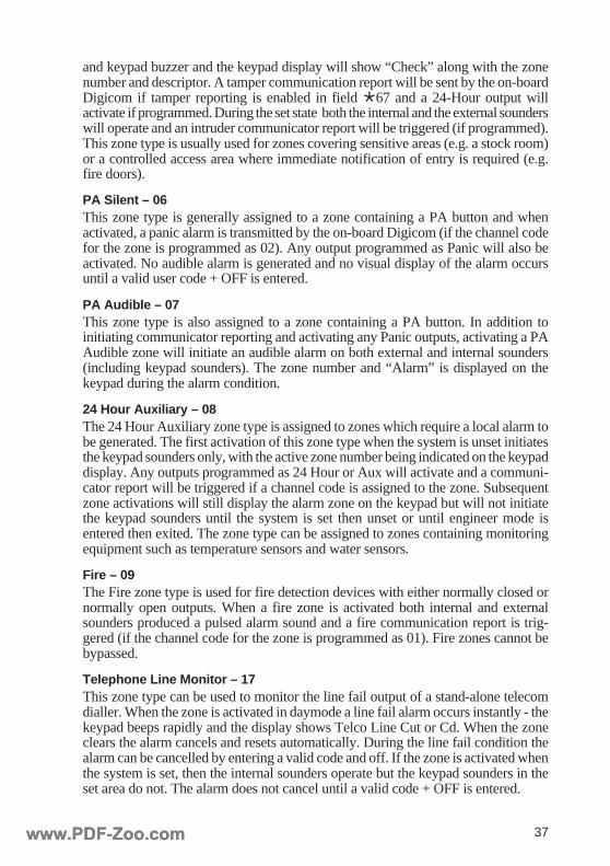
and keypad buzzer and the keypad display will show “Check” along with the zonenumber and descriptor. A tamper communication report will be sent by the on-boardDigicom if tamper reporting is enabled in field Ö67 and a 24-Hour output willactivate if programmed. During the set state both the internal and the external sounderswill operate and an intruder communicator report will be triggered (if programmed).This zone type is usually used for zones covering sensitive areas (e.g. a stock room)or a controlled access area where immediate notification of entry is required (e.g.fire doors).
PA Silent – 06This zone type is generally assigned to a zone containing a PA button and whenactivated, a panic alarm is transmitted by the on-board Digicom (if the channel codefor the zone is programmed as 02). Any output programmed as Panic will also beactivated. No audible alarm is generated and no visual display of the alarm occursuntil a valid user code + OFF is entered.
PA Audible – 07This zone type is also assigned to a zone containing a PA button. In addition toinitiating communicator reporting and activating any Panic outputs, activating a PAAudible zone will initiate an audible alarm on both external and internal sounders(including keypad sounders). The zone number and “Alarm” is displayed on thekeypad during the alarm condition.
24 Hour Auxiliary – 08The 24 Hour Auxiliary zone type is assigned to zones which require a local alarm tobe generated. The first activation of this zone type when the system is unset initiatesthe keypad sounders only, with the active zone number being indicated on the keypaddisplay. Any outputs programmed as 24 Hour or Aux will activate and a communi-cator report will be triggered if a channel code is assigned to the zone. Subsequentzone activations will still display the alarm zone on the keypad but will not initiatethe keypad sounders until the system is set then unset or until engineer mode isentered then exited. The zone type can be assigned to zones containing monitoringequipment such as temperature sensors and water sensors.
Fire – 09The Fire zone type is used for fire detection devices with either normally closed ornormally open outputs. When a fire zone is activated both internal and externalsounders produced a pulsed alarm sound and a fire communication report is trig-gered (if the channel code for the zone is programmed as 01). Fire zones cannot bebypassed.
Telephone Line Monitor – 17This zone type can be used to monitor the line fail output of a stand-alone telecomdialler. When the zone is activated in daymode a line fail alarm occurs instantly - thekeypad beeps rapidly and the display shows Telco Line Cut or Cd. When the zoneclears the alarm cancels and resets automatically. During the line fail condition thealarm can be cancelled by entering a valid code and off. If the zone is activated whenthe system is set, then the internal sounders operate but the keypad sounders in theset area do not. The alarm does not cancel until a valid code + OFF is entered.
www.PDF-Zoo.comwww.PDF-Zoo.com

38
Push to Set – 18This zone type is assigned to a zone connected to a Push to Set (Exit Terminate)button. In addition to programming the zone, programming field Ö11 must be set to1 ( if the button is to terminate Away setting only) or 2 (if the button is to terminateboth Away and Stay setting). If set to 1, Away set will only terminate when thebutton is pressed; Stay will terminate either when the button is pressed or after 30seconds. If set to 2 both Away and Stay sets will only terminate after the button ispressed.
Note: The setting procedure is initiated by entering a valid code at the keypad thenpressing Away or Stay. Pressing the Push To Set button will then terminatethe setting procedure and the system will be set. Subsequent pressing of thebutton will have no effect on the system.
Comms Hold-Off Zone – 19This zone type can be assigned to an output from a stand-alone dialler. When thezone is activated, any pending communication from the on-board Digicom will behalted to allow the stand-alone dialler to communicate first.
Stay Arm – 20When activated, a zone programmed as Stay Arm will initiate the Stay setting rou-tine. The system will then set after 30 seconds or with the Push to Set button, de-pending on Ö11 Setting Options. This can be done as an alternative to entering avalid user code + Stay.
Note: this zone type is not used for a zone which is isolated in Stay set. A zonebecomes isolated in Stay set by assigning the Isolate in Part Set zone optionto the zone (see Zone Options).
Away Arm – 21When activated, a zone programmed as Away Arm will initiate the Away settingroutine. This can be done as an alternative to entering a valid user code + Away.
Disarm – 22When activated during an Away or Stay set, a zone programmed as Disarm willcause the system to unset. This performs the same function as entering a valid usercode + OFF.
Trigger Output Only – 23Activation of a zone programmed as Trigger Output Only causes an output alsoprogrammed as Trigger Output Only to activate. This zone type has no other effecton the system.
www.PDF-Zoo.comwww.PDF-Zoo.com

39
Output Type DefinitionsThe output types listed in Table 4.1 are described below.
Fire – 01The Fire output type is activated by Fire zones in the Set and Unset state. The outputlatches on and will deactivate on the second entry of a valid code + OFF. The Fireoutput type is not affected by Bell Delay.
Panic – 02The Panic output type is activated by PA Silent zones, PA Audible zones and byentering a valid duress code at the keypad. The output deactivates on entry of a validcode + OFF.
Alarm – 03The Alarm output type is activated if an Intruder alarm condition occurs when thesystem is set (Away or Stay). When the system is Away set the following zone typeswill activate the Alarm output: Walk Through, Intruder, 24 Hour Tamper. When thesystem is Stay set only the Intruder and 24 hour tamper zone types will activate theAlarm output. The output deactivates on the second entry of a valid code + OFF. Ifengineer reset is enabled in field Ö24 then the engineer code must be used to deac-tivate the output.
Part Set – 04The Part Set output type is activated when the system is part set. A part set conditionoccurs when a valid code + STAY is used to set the system or when a valid code +AWAY is used after bypassing one or more zones. The output deactivates when thesystem is unset.
Set – 05The Set output type is activated when the system is full set (Away) and will deacti-vate when the system is unset. This output type is not affected by Stay set.
24 Hour – 07The 24 Hour output is activated by 24 Hour Tamper zones when the system is unsetand by 24 Hour Auxiliary zones when the system is set. The output deactivates onthe first entry of a valid code + Off.
Tamper – 08The Tamper output type is activated if a zone or a bell tamper condition occurs in theunset state. When the system is set a zone or bell tamper condition causes a fullIntruder alarm.
Set Latch Positive – 09The Set Latch output type activates when the system full sets (Away). The outputdeactivates when an Intruder alarm occurs, when the system is unset or when a FinalExit zone is activated. This output type is used to latch-on an LED on certain detec-tors (e.g. vibration detectors, latching PIRs) when the detector causes an alarm andalso to reset any latched detectors when the system is full set.
www.PDF-Zoo.comwww.PDF-Zoo.com
40
Fault / Trouble – 11The Fault / Trouble output type is activated by a mains fail, a line fail or by a lowbattery condition. When a mains fail occurs the condition must be present for 1 hourfor the output to activate. The output will deactivate with entry of a valid code + Off.
Communicator Fail – 12The Communicator Fail output type is activated after the dialler has attempted com-munication five times without establishing connection with the receiving centre.
Aux – 13The Aux output type is activated by 24 Hour Auxiliary zones in the set and unsetstate. The output deactivates on 1st entry of code + Off.
Abort – 14The Abort output type is activated on the first entry of a valid code + Off after anIntruder alarm condition . The output deactivates on the second entry of a valid code+ Off.
Verified – 15The Verified output type is activated by two Intruder alarms occurring in succession.The output deactivates on the first entry of a valid code + Off.
Prog – 16The Prog output type activates when Program Mode is entered and deactivates whenProgram Mode is exited.
Zone Type 23 – 17The Zone Type 23 output type is activated by zones programmed as Trigger OutputOnly (zone type 23) in the set or unset state. The output deactivates when the zone isdeactivated.
Line Fault – 19The Line Fault output type is activated 30 seconds after a line fail condition on theon-board Digicom or instantly by a zone programmed as Telephone Line Monitor.The output deactivates after the line fail condition clears.
Bell – 20The Bell output type is activated in a full alarm condition. The output deactivateswhen a valid code + Off is entered at the keypad or when the bell duration, pro-grammed in field Ö13, expires. If Bell Delay is enabled in programming field Ö12,then the output will not activate until the 10 minute bell delay expires.
Strobe – 21The strobe output type is activated in a full alarm condition and deactivates when avalid code + Off is entered at the keypad. The strobe output type also operates brieflyon full setting if programming field Ö16 Confirm for Strobe is enabled.
Internal Sounder – 22The internal sounder output type is activated in entry/exit and alarm conditions. Theoutput cancels when the condition clears.
www.PDF-Zoo.comwww.PDF-Zoo.com

41
Test Mode – 23The Test Mode output type activates when the system is put into test mode using avalid code + Test. The output deactivates on exit from test mode.
Ready – 26The Ready output type is activated in daymode when all zones are closed. The out-put deactivates when any zones are open.
Armed Confirmation – 27The armed confirmation output type activates when the system is full set. If theoutput is assigned to an expander, a single pulse lasting one second is produced. Ifthe output is on the Vista 20 then the output latches until a valid code + Off isentered. This output type only functions if programming field Ö16 Confirm for Strobeis enabled.
Entry – 28The Entry output type activates during the entry routine, i.e. when a Final Exit zoneis tripped during the set state. The output deactivates when a valid code + Off isentered at the keypad.
Exit – 29The Exit output type activates during the exit routine, i.e. after a valid code is used toStay or Away set the system. The output deactivates when the system has set.
Entry or Exit – 30The Entry or Exit output type activates during the entry routine and during the exitroutine. The output deactivates when the exit or entry routine is terminated.
Low Battery – 33The Low Battery output type activates during a low battery condition, i.e. when themains has been removed and the battery voltage has dropped to approximately 11Vdc. The output deactivates when the battery voltage has restored.
Mains Fail – 34The Mains Fail output type activates when the mains supply for the system has beenabsent for one hour. If the mains supply is restored during this period the output willnot activate.
Watchdog – 35The Watchdog output type activates if the system restarts for any reason, e.g. whenpower is applied after a complete power fail or after a software glitch.
Memory Fail – 36The Memory Fail output activates if the system memory becomes corrupt.
Chime – 37The Chime output type is activated by Chime zones in the unset state. If the output isassigned to an expander a single pulse lasting one second is produced. If the outputis on the Vista 20 then the output latches until a valid code + Off is entered.
www.PDF-Zoo.comwww.PDF-Zoo.com
42
Periodic Test – 39The Periodic Test output is activated when the system transmits a 24 hour test signalto the receiving centre. If the output is assigned to an expander a single pulse lastingone second is produced. If the output is on the Vista 20 then the output latches untila valid code + Off is entered.
User Code + 0 – 40The User code + 0 output type is activated by entering a valid user code + 0 at thekeypad. If the output is assigned to an expander a single pulse lasting one second isproduced. If the output is on the Vista 20 then the output latches until a valid code +Off is entered.
User Code 13 – 41The User Code 13 output type is activated by entering user code 13 at the keypad. Ifthe output is assigned to an expander a single pulse lasting one second is produced.If the output is on the Vista 20 then the output latches until a valid code + Off isentered.
User Code Assigned as Trigger Only – 42The User Code Assigned as Trigger Only output type is activated when a user codeassigned with the Trigger Only function in programming field Ö26/27 is entered atthe keypad. If the output is assigned to an expander a single pulse lasting one secondis produced. If the output is on the Vista 20 then the output latches until a valid code+ Off is entered.
www.PDF-Zoo.comwww.PDF-Zoo.com
43
SECTION 5: OPERATING THESYSTEM
The following sections explain the operation of the Vista 20 in daymode.
Setting and Unsetting the SystemIf the system is set by a user code then any valid user code can unset the system. Theengineer code can only unset the system if the engineer code was used for setting.Any valid user code can also unset a system set by the engineer code.
Full Setting the System1. Ensure that all zones are clear and that the building is empty of personnel.2. If “NOT READY” or “DISARMED - PRESS Ö” are shown on the display,
press the Ö key to view any open zones. If these zones are not on the exitroute, they must be cleared before setting.
3. Enter a valid code (or press ‘#’ , if quickarm is enabled) then press AWAY.A constant exit tone is generated on the internal sounder and keypads and theARMED LED illuminates. After the exit time has elapsed (or after the settingroutine is terminated) the warning tone stops. A double beep on the keypadindicates that the system is set. The ARMED LED deactivates when the systemis set, unless field Ö48 Display Armed Status for Away Set is enabled.
Part Setting the System1. Ensure that all zones which are active in Stay set are clear.2. Enter a valid code (or press the # key) then press the STAY key.
Unsetting the System1. Enter a valid code then press the OFF key.
Area Setting1. To set Area 1, enter an Area 1 code at an Area 1 keypad then press the
AWAY or STAY key.2. To set Area 2, enter an Area 2 code at an Area 2 keypad then press the
AWAY or STAY key.3. To set both Area 1 and Area 2 with one code, enter a code allocated to both
areas at an Area 1 keypad then press the AWAY or STAY key. Repeat theprocedure at an Area 2 keypad. If the code is User 1 then entering the code atone keypad will set both areas simultaneously.
Setting the System with a Mains Fail or a Line Fail1. Enter a valid code then press the BYPASS key followed by 00.2. Wait five seconds.2. Enter a valid code then press the AWAY or STAY key, as required.
Note: If setting with a line fail present, programming field Ö20 must be enabled.
www.PDF-Zoo.comwww.PDF-Zoo.com
44
Resetting After an AlarmThree reset modes are possible: Customer, Engineer and Coded (Technistore). Thereset mode is programmed in field Ö24 (see Engineer options in programming).
1. To silence the alarm, enter a valid code and then press the OFF key. The firstzone number displayed indicates where the alarm originated.
2. To reset the system, enter a valid code and then press the OFF key.If ‘CE’ or CALL ENGINEER is displayed, the system requires an engineerreset, i.e. enter the engineer code, then press the OFF key.If a list of numbers appears followed by ‘CE’ or ‘CALL CS QUOTE’, thesystem requires a coded reset. The five digit Technistore number displayedshould be quoted to the alarm monitoring station and a five digit anti-codeshould be obtained. This number should be entered at the keypad to reset thesystem.
Note: The system can be set up for combined engineer and coded reset. When inthis mode, an alarm condition can be reset either by entering the engineercode then OFF or by entering the Technistore anti-code.
Bypassing ZonesOne or more zones can be temporarily bypassed so that the zones are not active onthe next setting of the system. The zones must have their Bypass Inhibit optiondisabled for bypassing to be possible (see Zone Options in programming). The by-pass inhibit option is enabled by default and must therefore be changed before by-passing zones.
1. Enter a valid code and then press the BYPASS key followed by the zonenumber(s).A two digit number must be entered for each zone, i.e. 01 to 25 (excludingzone 09 - tamper).
2. Wait for five seconds. The system then confirms the bypassed zones on thedisplay.
3. Set the system by entering a valid code followed by the AWAY or STAYkey as required.
4. To remove all bypassed zones enter a valid code and then press the OFF key.Note: Any zones programmed as Fire or Panic cannot be bypassed.
www.PDF-Zoo.comwww.PDF-Zoo.com
45
Programming User CodesThe master code (user 01) is 1234 by default. It is strongly recommended that themaster user changes this code. The code can assign up to 14 additional codes. Themaster code is user 01 and the other users are numbered 02-15. In addition to user 1,any user code programmed as Master Area 1 or Master Area 2 in programming fieldÖ26 or Ö27 can change other user codes in the same area (see User Access Rightsin programming). The engineer code cannot change codes.
1. To assign a new code or change an existing code, enter the master code (User01) then press the CODE key followed by the two-digit user number (01 –15) then enter the new four digit code.After entering the new code a confirmation beep occurs on the keypad if thecode has been successfully changed.Entry of a code already in use results in the keypad beeping three times toindicate the fault. The procedure must be repeated to choose another code.
2. To delete a code, enter the master code then press the CODE key followed bythe user number (02 – 15) to be deleted. Wait five seconds. A confirmationbeep occurs at the keypad if the code has been successfully deleted.
Note: If the Master Code has been lost, entering Ö95 twice in engineer mode willset the code back to factory default (1234).
Panic AlarmA Panic Alarm can be initiated by activating a panic button connected to a zoneprogrammed as PA Audible or PA Silent. The Ö and # keys can also be used toinitiate a panic alarm if programming field Ö05 is programmed for a panic zoneresponse. The Ö and # keys must be pressed together to initiate the alarm.
For a PA Audible response, the zone number is indicated on the keypad display.This is displayed as zone 99 for the keypad panic. For a PA Silent, the zone numberis only displayed after entering a valid code and then pressing the OFF key.
To cancel the alarm, enter a valid code and then press the OFF key.
To reset the system, enter a valid code and then press the OFF key.
Fire AlarmSmoke detectors can be connected to any zone programmed as Fire. Activating thiszone type in the set or unset state will cause the internal and external sounders topulse on and off.
1. To silence the sounders, enter a valid code and then press the OFF key. Resetthe smoke detectors according to their instructions.
2. To reset the system enter a valid code and then press the OFF key.Note: The SW- (Switch Negative) connection can be used as a detector reset for
latching smoke detectors. The terminal should be connected to the negativesupply for the detector. The SW- output activates on the second entry of avalid code and OFF after the alarm condition.
www.PDF-Zoo.comwww.PDF-Zoo.com
46
DuressThe duress facility allows a panic signal to be transmitted if the user is forced toaccess the system under threat. A user code assigned as a duress code in program-ming field Ö26 or Ö27 (see User Access Rights in programming) can set and unsetthe system as normal but will also activate any outputs programmed as PA and willtrigger a Panic communicator report. No audible alarm occurs.
ChimeThis facility allows the internal sounders to Chime when certain zones are opened.To enable the Chime function on a zone(s):
1. Enter a valid code (user or engineer) and then press the CHIME key followedby the 2 digit zone number(s) to be put on Chime.
2. Wait five seconds. The keypad display then indicates which zones have theChime facility enabled.
3. Chime mode can be toggled on or off by entering a valid code and thenpressing the CHIME key.
4. The Chime function can be removed from all zones by entering a valid codethen pressing the CHIME key followed by 00.
Testing the systemAny valid code (engineer or user) can be used to test the system.
To enter test mode, enter a valid code and then press the TEST key. The internal andexternal sounders (bell) then operate for 3 seconds and the keypad display scrollsthrough each of the programmed zone numbers, allowing each zone to be tested. Onactivation of each zone the keypad buzzer and internal sounders beep and the zonenumber is removed from the list on the display. The strobe output will activate forthe duration of the test.
Once all zones have been tested the system will automatically exit Test Mode. Entera valid code and then press the OFF key to exit Test Mode manually.
The Master Code (user 01) and the engineer code can trigger a communicator testsignal by entering the code and then pressing the # key followed by the 5 key. TheTest option must be enabled in programming field Ö68.
Note: The keypad buzzer will sound a single beep every 15 seconds as a reminderthat the system is in Test Mode.
Setting the Time and DateThe time and date can be set by the master or engineer code.
1. Enter the code and then press the # key followed by the 9 key.2. Enter the time and date in the format: dd mm yy hh mm (i.e. day, month,
year, hours, minutes, all as two digits)
www.PDF-Zoo.comwww.PDF-Zoo.com
47
Viewing the Event LogThe Vista 20 has a 250 event memory. The full log can be viewed by the master codeor the engineer code using a 6139 full text keypad.
1. Enter the code and then press the # key followed by the 7 key.The most recent event is shown on the keypad display. The top line of thedisplay shows the time and date. The bottom line shows the event descriptionfollowed by the area, user number and zone number. The format is as follows:EEEEEEEE A ZZ UUWhere EEEEEEEE = event description, A = area, ZZ = zone number, UU =user number.
2. Use the 1 key to scroll backwards through the events and the 3 key to scrollforwards.
Note: The user number is always displayed. If the event is not affected by a usercode, e.g. an intruder alarm, the user number displayed is the last user toaccess the system.
The 6128 fixed text keypad cannot display the full log. It can be used to view a log ofthe alarm zones. Entering a valid code and then pressing the # key followed by the 8key displays the last zone to cause an alarm. The 1 key can be used to scroll back toview previous alarms and the 3 key to scroll forward.
Printing the Event LogThe full event log can be printed on exiting programming mode by enabling pro-gramming field Ö15. Two printer leads are required to enable connection from thepanel to an RS232 Serial Printer:
Master Printer Lead (part no. 2011-095) - connects from the printer to the AdapterPrinter Lead.
Adapter Printer Lead (part no. 2011-095) - connects from the control panel to theMaster Printer Lead.
The Adapter Printer Lead connects to the control panel using a three wire connec-tion. The three connections are the SW- terminal (yellow wire), the +12V Auxiliarysupply (red wire) and the -12V Auxiliary supply (black wire).
The printer settings should be as follows:
Data Bits 8Parity NoneBaud Rate 1200Country UKPrint Mode TextAuto Off DisabledEmulation StandardDTR Normal
Note: The event log can be uploaded from the panel using the Vista 20 Downloader.
www.PDF-Zoo.comwww.PDF-Zoo.com
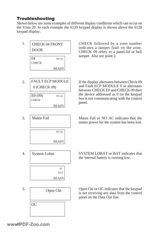
48
TroubleshootingShown below are some examples of different display conditions which can occur onthe Vista 20. In each example the 6139 keypad display is shown above the 6128keypad display.
1. CHECK followed by a zone numberindicates a tamper fault on the zone.CHECK 09 refers to a panel-lid or belltamper. Also see point 2.
2. If the display alternates between Check 09and Fault ECP MODULE 0 or alternatesbetween CHECK E0 and CHECK 09 thenthe device addressed as 0 on the keypadbus is not communicating with the controlpanel.
3. Mains Fail or NO AC indicates that themains power for the system has been lost.
4. SYSTEM LOBAT or BAT indicates thatthe internal battery is running low.
5. Open Ckt or OC indicates that the keypadis not receiving any data from the controlpanel on the Data Out line.
Mains Fail
System Lobat
Open Ckt
NO AC
READY
04 NO AC
CHECK
READY
CHECK 04 FRONT
DOOR
OC
AC
BAT
READY
E0 (09) NO AC
CHECK
READY
FAULT ECP MODULE
0 (CHECK 09)
www.PDF-Zoo.comwww.PDF-Zoo.com
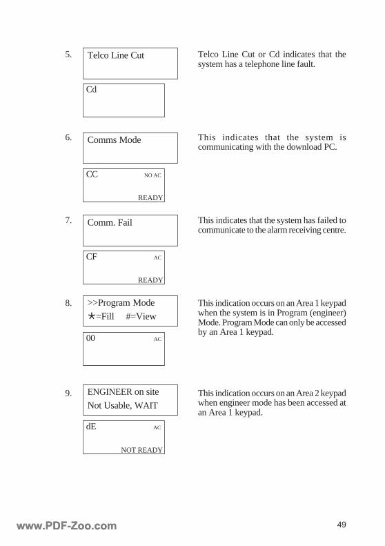
49
5. Telco Line Cut or Cd indicates that thesystem has a telephone line fault.
6. This indicates that the system iscommunicating with the download PC.
7. This indicates that the system has failed tocommunicate to the alarm receiving centre.
8. This indication occurs on an Area 1 keypadwhen the system is in Program (engineer)Mode. Program Mode can only be accessedby an Area 1 keypad.
9. This indication occurs on an Area 2 keypadwhen engineer mode has been accessed atan Area 1 keypad.
Telco Line Cut
Cd
Comms Mode
CF AC
READY
Comm. Fail
CC NO AC
READY
>>Program Mode
Ö=Fill #=View
00 AC
ENGINEER on site
Not Usable, WAIT
dE AC
NOT READY
www.PDF-Zoo.comwww.PDF-Zoo.com
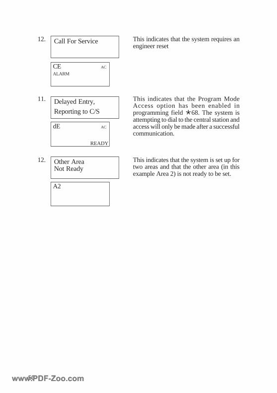
50
12. This indicates that the system requires anengineer reset
11. This indicates that the Program ModeAccess option has been enabled inprogramming field Ö68. The system isattempting to dial to the central station andaccess will only be made after a successfulcommunication.
12. This indicates that the system is set up fortwo areas and that the other area (in thisexample Area 2) is not ready to be set.
Other AreaNot Ready
A2
dE AC
READY
Delayed Entry,
Reporting to C/S
CE AC
ALARM
Call For Service
www.PDF-Zoo.comwww.PDF-Zoo.com

51
APPENDIX A: SPECIFICATIONS
Vista 20 Control Panel
PhysicalWidth 238mm
Height 304mm
Depth 80mm
ElectricalMains Input 230 V a.c. (+10% – 6%) 50Hz
Stand-by Battery Up to 7Ahr 12 V Sealed lead acid
Aux Power Output 12 V d.c., 1 A max.
Output Triggers 12V d.c. (0V in alarm)
5 mA maximum sink current
6139 Full Text Keypad
PhysicalWidth 160 mm
Height 120 mm
Depth 31 mm
ElectricalVoltage Input 12 V d.c.
Current drain 60 mA
100 mA in alarm
6128UK Fixed Text Keypad
PhysicalWidth 146 mm
Height 120 mm
Depth 25 mm
ElectricalVoltage Input 12 V d.c.
Current Drain 20 mA (60 mA in alarm)
www.PDF-Zoo.comwww.PDF-Zoo.com
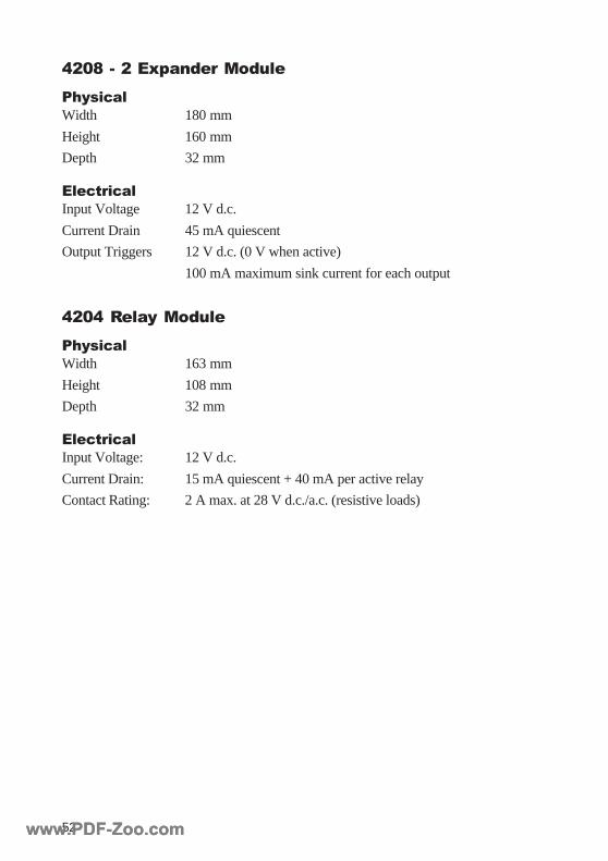
52
4208 - 2 Expander Module
PhysicalWidth 180 mm
Height 160 mm
Depth 32 mm
ElectricalInput Voltage 12 V d.c.
Current Drain 45 mA quiescent
Output Triggers 12 V d.c. (0 V when active)
100 mA maximum sink current for each output
4204 Relay Module
PhysicalWidth 163 mm
Height 108 mm
Depth 32 mm
ElectricalInput Voltage: 12 V d.c.
Current Drain: 15 mA quiescent + 40 mA per active relay
Contact Rating: 2 A max. at 28 V d.c./a.c. (resistive loads)
www.PDF-Zoo.comwww.PDF-Zoo.com

53
ADEMCO LIMITED WARRANTY
Alarm Device Manufacturing Company, a Division of Pittway Corporation, and its divisions, subsidi-aries and affiliates (“Seller”), 165 Eileen Way, Syosset, New York, 11791, warrants its products to bein conformance with its own plans and specifications and to be free from defects in materials andworkmanship under normal use and service for 18 months from the date stamp control on the productor, for products not having an Ademco date stamp, for 12 months from date of original purchase unlessthe installation instructions or catalogue sets forth a shorter period, in which case the shorter periodshall apply. Seller’s obligation shall be limited to repairing or replacing, at its option, free of chargefor materials or labour, any product which is proved not in compliance with Seller’s specifications orproves defective in materials or workmanship under normal use and service. Seller shall have noobligation under this Limited Warranty or otherwise if the product is altered or improperly repaired orserviced by anyone other than Ademco factory service. For warranty service, return product transpor-tation prepaid to:
Ademco-Microtech Ltd, 3 Wellington Crescent, Fradley Park, Lichfield, Staffs, WS13 8RZ.
THERE ARE NO WARRANTIES, EXPRESS OR IMPLIED, OF MERCHANTABILITY, OR FIT-NESS FOR A PARTICULAR PURPOSE OR OTHERWISE, WHICH EXTEND BEYOND THEDESCRIPTION ON THE FACE HEREOF. IN NO CASE SHALL SELLER BE LIABLE TO ANY-ONE FOR ANY CONSEQUENTIAL OR INCIDENTAL DAMAGES FOR BREACH OF THIS ORANY OTHER WARRANTY, EXPRESS OR IMPLIED, OR UPON ANY OTHER BASIS OF LI-ABILITY WHATSOEVER, EVEN IF THE LOSS OR DAMAGE IS CAUSED BY THE SELLER’SOWN NEGLIGENCE OR FAULT.
Seller does not represent that the products it sells may not be compromised or circumvented; that theproducts will prevent any personal injury or property loss by burglary, robbery, fire or otherwise; orthat the products will in all cases provide adequate warning or protection. Customer understands thata properly installed and maintained alarm may only reduce the risk of a burglary, robbery, fire or otherevents occurring without providing an alarm, but it is not insurance or a guarantee that such will notoccur or that there will be no personal injury or property loss as a result. CONSEQUENTLY, SELLERSHALL HAVE NO LIABILITY FOR ANY PERSONAL INJURY, PROPERTY DAMAGE OROTHER LOSS BASED ON A CLAIM THE PRODUCT FAILED TO GIVE WARNING. HOW-EVER, IF SELLER IS HELD LIABLE, WHETHER DIRECTLY OR INDIRECTLY, FOR ANY LOSSOR DAMAGE ARISING UNDER THIS LIMITED WARRANTY OR OTHERWISE, REGARD-LESS OF CAUSE OR ORIGIN, SELLER’S MAXIMUM LIABILITY SHALL NOT IN ANY CASEEXCEED THE PURCHASE PRICE OF THE PRODUCT, WHICH SHALL BE THE COMPLETEAND EXCLUSIVE REMEDY AGAINST SELLER. This warranty replaces any previous warrantiesand is the only warranty made by Seller on this product. No increase or alteration, written or verbal, ofthe obligations of this Limited Warranty is authorised.
ADEMCOMicrotech Ltd.
3 Wellington Crescent
Fradley Park
Lichfield
Staffs
WS13 8RZ
A division of the Pittway corporation © Copyright Pittway Corporation
www.PDF-Zoo.comwww.PDF-Zoo.com

54
IE1-0020 (ISSUE A)8/7/99
www.PDF-Zoo.comwww.PDF-Zoo.com
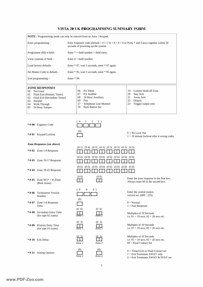
1
( 4 1 1 5 ) */# 00 Engineer Code (0) */# 01 Keypad Lockout Zone Responses (see above) (0 1) (0 4) (0 3) (0 3) (0 3) (0 3) (0 3) (0 3) */# 02 Zone 1-8 Response (0 0) (0 0) (0 0) (0 0) (0 0) (0 0) (0 0) (0 0) */# 03 Zone 10-17 Response (0 0) (0 0) (0 0) (0 0) (0 0) (0 0) (0 0) (0 0) */# 04 Zone 18-25 Response (0 0) (0 0) */# 05 Zone 99 (* + #) Panic (Both Areas) ( 0 0 0 ) */# 06 Technistore Version Number (0) */# 07 Zone 1-8 Response Time (0 6) (0 6) */# 08 Secondary Entry Time (for type 02 zones) Area 1 Area 2 (0 3) (0 3) */# 09 Primary Entry Time (for type 01 zones) Area 1 Area 2
(0 3) (0 3) */# 10 Exit Delay Area 1 Area 2 (0) (0) */# 11 Setting Options Area 1 Area 2
ZONE RESPONSES 00 Not Used 01 Final Exit (Primary Timer) 02 Final Exit (Secondary Timer) 03 Intruder 04 Walk Through 05 24 Hour Tamper
06 PA Silent 07 PA Audible 08 24 Hour Auxiliary 09 Fire 17 Telephone Line Monitor 18 Push Button Set
19 Comms Hold-off Zone 20 Stay Arm 21 Away Arm 22 Disarm 23 Trigger output only
NOTE : Programming mode can only be entered from an Area 1 Keypad. Enter programming - Enter Engineer code (default = 4 1 1 5) + 8 + 0 + 0 or Press * and # keys together within 20 seconds of powering up the system. Programme (fill) a field - Enter * + field number + field entry. View contents of field - Enter # + field number. Load factory defaults - Enter * 97, wait 5 seconds, enter * 97 again. Set Master Code to default - Enter * 95, wait 5 seconds, enter * 95 again. Exit programming - Enter * 99.
Multiples of 10 Seconds i.e. 01 = 10 secs, 02 = 20 secs etc.
Multiples of 10 Seconds i.e. 01 = 10 secs, 02 = 20 secs etc.
Multiples of 10 Seconds i.e. 01 = 10 secs, 02 = 20 secs etc. 00 = Final Contact Set
0 = Normal 1 = Fast Response
Enter the central station version no. (000 - 255)
0 = Timed Exit or Final Contact set 1 = Exit Terminate AWAY only 2 = Exit Terminate AWAY & STAY set
0 = No Lock Out 1 = 10 minute lockout after 4 wrong codes
Enter the zone response in the first box. Always enter 00 in the second box.
www.PDF-Zoo.comwww.PDF-Zoo.com
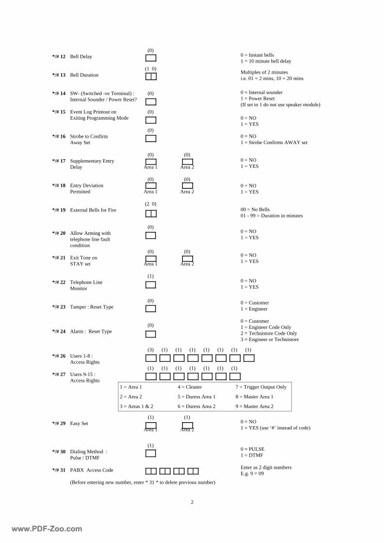
2
(0) */# 20 Allow Arming with telephone line fault condition (0) (0) */# 21 Exit Tone on STAY set Area 1 Area 2 (1) */# 22 Telephone Line Monitor (0) */# 23 Tamper : Reset Type (0) */# 24 Alarm : Reset Type (3) (1) (1) (1) (1) (1) (1) (1) */# 26 Users 1-8 : Access Rights (1) (1) (1) (1) (1) (1) (1) */# 27 Users 9-15 : Access Rights (1) (1) */# 29 Easy Set Area 1 Area 2
(1) */# 30 Dialing Method : Pulse / DTMF */# 31 PABX Access Code (Before entering new number, enter * 31 * to delete previous number)
(0) */# 12 Bell Delay (1 0) */# 13 Bell Duration */# 14 SW- (Switched -ve Terminal) : (0) Internal Sounder / Power Reset? */# 15 Event Log Printout on (0) Exiting Programming Mode (0) */# 16 Strobe to Confirm Away Set (0) (0) */# 17 Supplementary Entry Delay Area 1 Area 2 (0) (0) */# 18 Entry Deviation Permitted Area 1 Area 2 (2 0) */# 19 External Bells for Fire
0 = Instant bells 1 = 10 minute bell delay
Multiples of 2 minutes i.e. 01 = 2 mins, 10 = 20 mins
0 = Customer 1 = Engineer
0 = Customer 1 = Engineer Code Only 2 = Technistore Code Only 3 = Engineer or Technistore
0 = Internal sounder 1 = Power Reset (If set to 1 do not use speaker module)
0 = NO 1 = Strobe Confirms AWAY set
00 = No Bells 01 - 99 = Duration in minutes
0 = NO 1 = YES
0 = NO 1 = YES
0 = NO 1 = YES
0 = NO 1 = YES
0 = NO 1 = YES
0 = NO 1 = YES
1 = Area 1 4 = Cleaner 7 = Trigger Output Only
2 = Area 2 5 = Duress Area 1 8 = Master Area 1
3 = Areas 1 & 2 6 = Duress Area 2 9 = Master Area 2
0 = NO 1 = YES (use ‘#’ instead of code)
0 = PULSE 1 = DTMF
Enter as 2 digit numbers E.g. 9 = 09
www.PDF-Zoo.comwww.PDF-Zoo.com
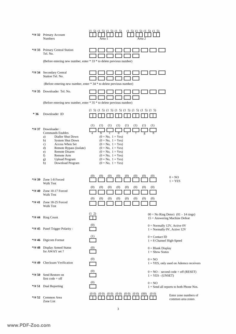
3
(0) (0) (0) (0) (0) (0) (0) (0) */# 39 Zone 1-8 Forced Walk Test (0) (0) (0) (0) (0) (0) (0) (0) */# 40 Zone 10-17 Forced Walk Test (0) (0) (0) (0) (0) (0) (0) (0) */# 41 Zone 18-25 Forced Walk Test (1 2) */# 44 Ring Count (0) */# 45 Panel Trigger Polarity : (1) */# 46 Digicom Format */# 48 Display Armed Status (0) for AWAY set ? (0) */# 49 Checksum Verification
(1 5) (1 5) (1 5) (1 5) (1 5) (1 5) (1 5) (1 5) */# 32 Primary Account Numbers Area 1 Area 2 */# 33 Primary Central Station Tel. No. (Before entering new number, enter * 33 * to delete previous number) */# 34 Secondary Central Station Tel. No. (Before entering new number, enter * 34 * to delete previous number) */# 35 Downloader Tel. No. (Before entering new number, enter * 35 * to delete previous number) (1 5) (1 5) (1 5) (1 5) (1 5) (1 5) (1 5) (1 5) * 36 Downloader ID (1) (1) (1) (1) (1) (1) (1) (1) */# 37 Downloader : Commands Enables a b c d e f g h a) Dialler Shut Down (0 = No, 1 = Yes) b) System Shut Down (0 = No, 1 = Yes) c) Access When Set (0 = No, 1 = Yes) d) Remote Bypass (isolate) (0 = No, 1 = Yes) e) Remote Disarm (0 = No, 1 = Yes) f) Remote Arm (0 = No, 1 = Yes) g) Upload Program (0 = No, 1 = Yes) h) Download Program (0 = No, 1 = Yes)
(0) */# 50 Send Restore on first code + off (0) */# 51 Dual Reporting (0 0) (0 0) (0 0) (0 0) (0 0) (0 0) (00) (0 0) */# 52 Common Area Zone List
0 = Contact ID 1 = 8 Channel High-Speed
0 = Normally 12V, Active 0V 1 = Normally 0V, Active 12V
0 = Blank Display 1 = Show Status
00 = No Ring Detect (01 – 14 rings) 15 = Answering Machine Defeat
0 = NO 1 = YES
0 = NO 1 = YES, only used on Ademco receivers
0 = NO 1 = Send all reports to both Phone Nos.
0 = NO - second code + off (RESET) 1 = YES - (UNSET)
Enter zone numbers of common area zones
www.PDF-Zoo.comwww.PDF-Zoo.com
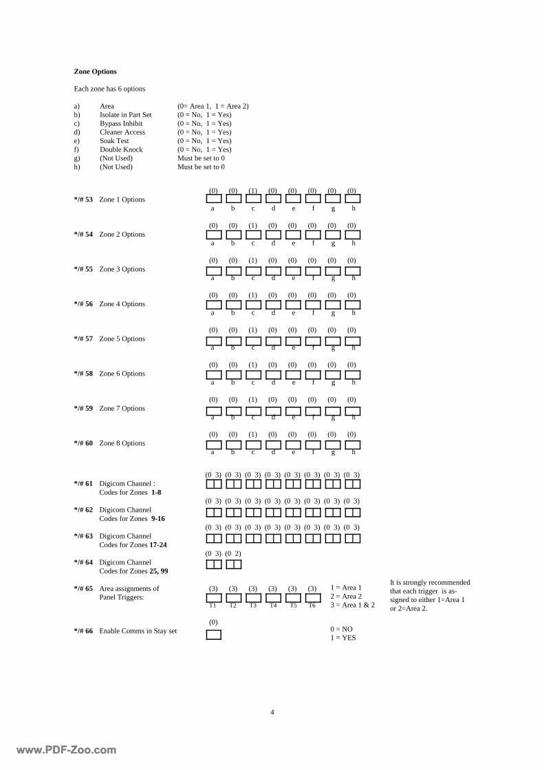
4
(0) (0) (1) (0) (0) (0) (0) (0) */# 53 Zone 1 Options a b c d e f g h (0) (0) (1) (0) (0) (0) (0) (0) */# 54 Zone 2 Options a b c d e f g h (0) (0) (1) (0) (0) (0) (0) (0) */# 55 Zone 3 Options a b c d e f g h (0) (0) (1) (0) (0) (0) (0) (0) */# 56 Zone 4 Options a b c d e f g h (0) (0) (1) (0) (0) (0) (0) (0) */# 57 Zone 5 Options a b c d e f g h (0) (0) (1) (0) (0) (0) (0) (0) */# 58 Zone 6 Options a b c d e f g h (0) (0) (1) (0) (0) (0) (0) (0) */# 59 Zone 7 Options a b c d e f g h (0) (0) (1) (0) (0) (0) (0) (0) */# 60 Zone 8 Options a b c d e f g h
(0 3) (0 3) (0 3) (0 3) (0 3) (0 3) (0 3) (0 3) */# 61 Digicom Channel : Codes for Zones 1-8 (0 3) (0 3) (0 3) (0 3) (0 3) (0 3) (0 3) (0 3) */# 62 Digicom Channel Codes for Zones 9-16 (0 3) (0 3) (0 3) (0 3) (0 3) (0 3) (0 3) (0 3) */# 63 Digicom Channel Codes for Zones 17-24 (0 3) (0 2) */# 64 Digicom Channel Codes for Zones 25, 99 */# 65 Area assignments of (3) (3) (3) (3) (3) (3) Panel Triggers: T1 T2 T3 T4 T5 T6 (0) */# 66 Enable Comms in Stay set
Zone Options Each zone has 6 options a) Area (0= Area 1, 1 = Area 2) b) Isolate in Part Set (0 = No, 1 = Yes) c) Bypass Inhibit (0 = No, 1 = Yes) d) Cleaner Access (0 = No, 1 = Yes) e) Soak Test (0 = No, 1 = Yes) f) Double Knock (0 = No, 1 = Yes) g) (Not Used) Must be set to 0 h) (Not Used) Must be set to 0
1 = Area 1 2 = Area 2 3 = Area 1 & 2
It is strongly recommended that each trigger is as-signed to either 1=Area 1 or 2=Area 2.
0 = NO 1 = YES
www.PDF-Zoo.comwww.PDF-Zoo.com
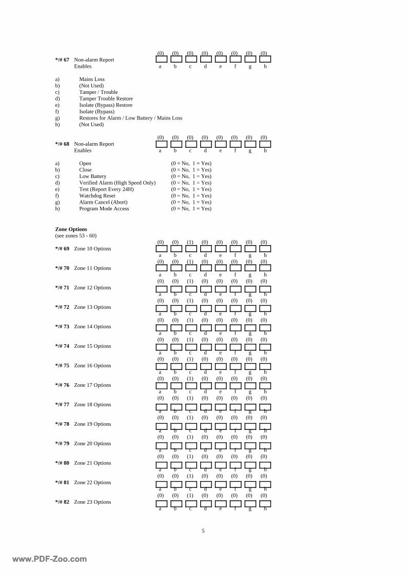
5
(0) (0) (0) (0) (0) (0) (0) (0) */# 67 Non-alarm Report Enables a b c d e f g h a) Mains Loss b) (Not Used) c) Tamper / Trouble d) Tamper Trouble Restore e) Isolate (Bypass) Restore f) Isolate (Bypass) g) Restores for Alarm / Low Battery / Mains Loss h) (Not Used) (0) (0) (0) (0) (0) (0) (0) (0) */# 68 Non-alarm Report Enables a b c d e f g h a) Open (0 = No, 1 = Yes) b) Close (0 = No, 1 = Yes) c) Low Battery (0 = No, 1 = Yes) d) Verified Alarm (High Speed Only) (0 = No, 1 = Yes) e) Test (Report Every 24H) (0 = No, 1 = Yes) f) Watchdog Reset (0 = No, 1 = Yes) g) Alarm Cancel (Abort) (0 = No, 1 = Yes) h) Program Mode Access (0 = No, 1 = Yes)
Zone Options (see zones 53 - 60) (0) (0) (1) (0) (0) (0) (0) (0) */# 69 Zone 10 Options a b c d e f g h (0) (0) (1) (0) (0) (0) (0) (0) */# 70 Zone 11 Options a b c d e f g h (0) (0) (1) (0) (0) (0) (0) (0) */# 71 Zone 12 Options a b c d e f g h (0) (0) (1) (0) (0) (0) (0) (0) */# 72 Zone 13 Options a b c d e f g h (0) (0) (1) (0) (0) (0) (0) (0) */# 73 Zone 14 Options a b c d e f g h (0) (0) (1) (0) (0) (0) (0) (0) */# 74 Zone 15 Options a b c d e f g h (0) (0) (1) (0) (0) (0) (0) (0) */# 75 Zone 16 Options a b c d e f g h (0) (0) (1) (0) (0) (0) (0) (0) */# 76 Zone 17 Options a b c d e f g h (0) (0) (1) (0) (0) (0) (0) (0) */# 77 Zone 18 Options a b c d e f g h (0) (0) (1) (0) (0) (0) (0) (0) */# 78 Zone 19 Options a b c d e f g h (0) (0) (1) (0) (0) (0) (0) (0) */# 79 Zone 20 Options a b c d e f g h (0) (0) (1) (0) (0) (0) (0) (0) */# 80 Zone 21 Options a b c d e f g h (0) (0) (1) (0) (0) (0) (0) (0) */# 81 Zone 22 Options a b c d e f g h (0) (0) (1) (0) (0) (0) (0) (0) */# 82 Zone 23 Options a b c d e f g h
www.PDF-Zoo.comwww.PDF-Zoo.com
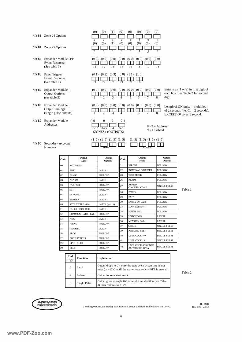
6
(0) (0) (1) (0) (0) (0) (0) (0) */# 83 Zone 24 Options a b c d e f g h (0) (0) (1) (0) (0) (0) (0) (0) */# 84 Zone 25 Options a b c d e f g h */# 85 Expander Module O/P (0 0) (0 0) (0 0) (0 0) (0 0) (0 0) (0 0) (0 0) Event Response (See table 1) T1 T2 T3 T4 T5 T6 T7 T8 */# 86 Panel Trigger : (0 1) (0 2) (0 3) (0 8) (1 1) (1 6) Event Response (See table 1) T1 T2 T3 T4 T5 T6 */# 87 Expander Module : (0 0) (0 0) (0 0) (0 0) (0 0) (0 0) (0 0) (0 0) Output Options (see table 2) 1 2 3 4 5 6 7 8 */# 88 Expander Module : (0 0) (0 0) (0 0) (0 0) (0 0) (0 0) (0 0) (0 0) Output Timings (single pulse outputs) 1 2 3 4 5 6 7 8 */# 89 Expander Module : ( 9 9 9 9 ) Addresses 10-17 18-25 1-4 5-8 (ZONES) (OUTPUTS) (1 5) (1 5) (1 5) (1 5) (1 5) (1 5) (1 5) (1 5) */# 90 Secondary Account Numbers Area 1 Area 2
0 - 3 = Address 9 = Disabled
IP1-9910 Rev 2.00 - 2/6/99
2ndDigit
Function Explanation
0 LatchOutput drops to 0V once the start event occurs and is notreset (to +12V) until the master/user code + OFF is entered
2 Follow Output follows start event
3 Single PulseOutput gives a single 0V pulse of a set duration (see Table3) then restores to +12V
Length of ON pulse = multiples of 2 seconds ( ie. 01 = 2 seconds). EXCEPT 00 gives 1 second.
Table 1
Table 2
3 Wellington Crescent, Fradley Park Industrial Estate, Lichfield, Staffordshire. WS13 8RZ.
CodeOutputTypes
OutputOptions
00 NOT USED –
01 FIRE LATCH
02 PANIC FOLLOW
03 ALARM LATCH
04 PART SET FOLLOW
05 SET FOLLOW
07 24 HOUR LATCH
08 TAMPER LATCH
09 SET LATCH Positive LATCH (special)
11 FAULT / TROUBLE LATCH
12 COMMUNICATOR FAIL FOLLOW
13 AUX LATCH
14 ABORT FOLLOW
15 VERIFIED LATCH
16 PROG FOLLOW
17 ZONE TYPE 23 FOLLOW
19 LINE FAULT FOLLOW
20 BELL FOLLOW
CodeOutputTypes
OutputOptions
21 STROBE FOLLOW
22 INTERNAL SOUNDER FOLLOW
23 TEST MODE FOLLOW
26 READY FOLLOW
27ARMEDCONFIRMATION
SINGLE PULSE
28 ENTRY FOLLOW
29 EXIT FOLLOW
30 ENTRY OR EXIT FOLLOW
33 LOW BATTERY FOLLOW
34 MAINS FAIL FOLLOW
35 WATCHDOG LATCH
36 MEMORY FAIL LATCH
37 CHIME SINGLE PULSE
39 PERIODIC TEST SINGLE PULSE
40 USER CODE + 0 SINGLE PULSE
41 USER CODE 13 SINGLE PULSE
42USER CODE ASSIGNEDAS TRIGGER ONLY
SINGLE PULSE
Enter area (1 or 2) in first digit of each box. See Table 2 for second digit
www.PDF-Zoo.comwww.PDF-Zoo.com