visualisation of jet fires from hydrogen release
TRANSCRIPT

VISUALISATION OF JET FIRES FROM HYDROGEN RELEASE
L. Deimling, V. Weiser, A. Blanc, N. Eisenreich, G. Billeb, A. Kessler Fraunhofer ICT, J-v-Fraunhoferstr. 7, 76327 Pfinztal, Germany
ABSTRACT In order to achieve a high level of safety while using hydrogen as a vehicle fuel, the possible hazards must be estimated. Especially hydrogen release tests with defined ignition represent a very important way to characterize the basics of hydrogen combustion in a potential accident. So ICT participated on a hydrogen jet release campaign at HSL (Buxton) in 2008, to deploy their measurement techniques and evaluation methods to visualize jets, ignition and subsequent flames. The following paper shows the application of high speed cinematography in combination with image processing techniques, the Background Oriented Schlieren (BOS) and a difference method to visualize the shape of hydrogen jet. In addition, these methods were also used to observe ignition and combustion zone after defined initiation. In addition the combustion zone was recorded by a fast spectral radiometer and a high-speed-IR-camera. The IR-camera was synchronized with a rotating filter wheel to generate four different motion pictures at 100Hz each on a defined spectral range. The results of this preliminary evaluation provide some detailed information that might be used for improving model predictions.
1.0 INTRODUCTION
Many important industrial processes with chemical reactions store hydrocarbons or hydrogen in pressurized closed vessels. Depending on the process or in the case of leakages, these gases may be mixed with air or oxygen so they might ignite, burn, explode or even detonate. Gas explosions in closed vessels produce high pressure forces on the complete enclosure which can lead to total damage of a reactor or to leakages to release the complete stored mass of gas. The possible subsequent explosive reactions can take place in wide ranges of fuel/oxidizer compositions with flame velocities up to more than 100 meter per second, which are strongly enhanced by in spherical explosions and turbulence [1 - 5]. Beneath the pressure waves, radiation is the main effect to influence the surroundings and contribute in fire and explosion transfer and propagation. Especially, the dominating risks of hydrogen jet fires emerge from direct contact of the flame and its reacting species, the dispersion of hot gases and, for remote distances, the radiation. The radiative emission of hazardous fires and gas/liquid explosions is strongly variable in time by jets lasting till shut down or the complete release at short scales down to milliseconds [6]. In addition, it includes fundamental information concerning the mechanisms and progress of burning. A scanning analysis of the spectral flame radiation must record the flame dimensions, be fast enough to detect pre-reactions, transient phenomena, starting explosions, enable the understanding of propagation mechanisms as well as quenching or extinguishing mechanisms. For fires and explosion hazards these investigations are able to provide safety engineers with a basis to develop effective methods for early detection and identification of effects, safety distances and shielding measures, prevention or suppression and for effective fire fighting and explosion suppression. In contrast to pressure effects, time and spectrally resolved radiation of fires and explosions is not investigated in a sufficient way, especially concerning spectral resolution and influence on environment. There exist only a limited number of publications on measurements resolved in time and wavelength [6 - 11]. For example a jet combustion was spectrally resolved in time when released from a 75 l hydrogen tank, not reporting the full shape of the jet [10]. However, the evaluations need the transient shape of the burning jets to estimate the volume which emits radiation and this shape has to be recorded depending on time and resolved in sub-structures like turbulence patterns. This paper reports evaluations of joint experiments under the work programme of Hysafe occurring at HSL (Buxton) in 2008 who provided the test facilities and jet fires as well as the basic measurements of pressures together with Fraunhofer ICT applying their equipment to visualise

the jet fires by fast video techniques, thermo cameras and fast scanning spectroscopy in the Near infrared and Infrared (NIR/IR) spectral region. The evaluation presented here concerns the optical analysis by various image analysis techniques. More details will be included in further papers to take care of a high amount of information from 23 jet experiments (named HyperXX), all at a time resolution of less than 10 ms. A separate paper “Evaluation of Optical and Spectroscopic (NIR/IR) Experiments of Hydrogen Jet Fires” reports spectral investigations.
2.0 EXPERIMENTAL SETUP
In the experimental campaign the test site at HSL generated hydrogen jets with different sizes. Hydrogen was supplied from a 100 l tank which was pressurised by 20MPa and released to the free air restricted by orifices varying in diameter from 1.5 to 10 mm. On progress of the test there was an exponential decay of the pressure in the tank depending on the orifice diameter. The outlet for the jet release was mounted horizontally. The ignition occurred by an electrical igniter for a jet engine and in some cases by a squib. The ignition point was located 2.2 or 2.5 m downstream the jet flow. The applied Fraunhofer equipment consists of high-speed-camera-technique, a thermo-camera and a spectral radiometer for the IR-range between 1.6 and 14.5 microns with maximal scan rates of 100 scans / s. The thermo camera included 4 wavelength filters in the NIR/IR and was used to observe the whole flame whereas the spectral radiometer only observed one isolated spot of size 0.2 m2. The high-speed-cameras with a maximum frame rate of 1000 fps at full resolution were used for Background-Oriented-Schlieren-method (BOS). Therefore a random pattern of black dots on a white surface was placed 4 meters behind the centre line of the jet flame. The high-speed-cameras were recording the wall pattern perpendicular from a distance of 14.6 meters at 90°. The spectral radiometer and the IR-camera had a distance of 38.5 m at an aspect angle of about 80°. The setup is shown in a sketch in figure 1. Data of the tests are summarized together with results in table 1.
Figure 1: Sketch of the experimental setup
3.0 HIGH SPEED FLAME VISUALISATION
The spatial distribution of species and temperature as well as their time history and fluctuations give a basis of the evaluation to the main risks of such jet fires. The hydrogen jet and especially the flame are not directly visible in the visual spectral range. Hydrogen itself is a colourless gas and the jets can be observed mainly by their fluctuations in density and density differences against background initiated on transient flow fields. The flame emits only in the UV, the OH bands located with the strongest band

at 306 nm and various series of strong water bands in the NIR and IR spectral regions [6, 8-10]. However, the techniques of BOS and difference images can clearly visualise jets and flames, naturally also IR-cameras. The origin of the BOS method was the particle image velocimetry [12, 13], mainly developed by the DLR for applications in fluids [14, 15]. In an earlier paper the principles were described more in detail applying the technique to hydrogen problems [16] where the flow fields of hydrogen jets and explosions were visualised against a background pattern. In addition, an image difference technique was used to analyse the frames of the high speed videos [16]. The use of difference images was already described for hydrogen air deflagration by Otsuka et al [17, 18]. In addition, the combination of these techniques of image processing gives improved visual impression of the flow fields and flames. This means that the processed images could be added or subtracted from each other or even combined with the original picture. Some examples are given in the following diagrams. The flame length and the flame speeds were achieved by summing up the brightness of all lines of a frame and generate a position/time diagram of these summary lines versus time. It is still difficult to decide on the true contour of the bright flame emission because the cut-off levels are set arbitrarily, and not all influences, such as sensitivity, brightness, distances etc, are not accounted for. The high speed video used 1000 fps and the thermo (IR) camera with 100 fps for each of 4 filter ranges. In figure 2 the original video frames are compared with different variants of image analysis:
(a)
(b)
(c)
(d)
Figure 2: Single high speed image of a Hydrogen jet stream propagating into open air – (a) original video image – (b) highly resolved vector field of BOS evaluation – (c) BOS value pattern superimposed with original image - (d) image of brightness difference (frame 175 – frame 1) optimized by filter methods (experiment HYPER06)

The jet itself which is nearly invisible in the original frames can be visualized via various methods, the BOS method, the brightness subtraction and a combination with the original frame. Still the type of presentation of the image is free and can be chosen according to personal preferences. On triggering the valve a hydrogen jet evolves from the nozzle forming a typical conical shape. It displays a turbulent structure which increases with distance from the nozzle. The velocity of the jet head does not correspond to an orifice diameter, because the interval of the valve opening interferes the timescale. The turbulence indicates strong air entrainment. The cone half angle was to be between 8 and 10o (Fig.3) independent of the orifice diameter, an angel which is generally found for such jets [19-21].
Frame no. 126 (t = 0.010ms)
Frame no. 160 (t = 0.044ms)
Frame no. 200 (t = 0.084ms)
Frame no. 250 (t = 0.134ms)
Figure 3: High speed frames from a jet propagating into open air, brightness difference at various time steps (experiment HYPER20)
The type of evaluation does not influence strongly the dimensions of the visualised jet, more do the cut-off levels. The main influence is by the turbulence which increases with distance from the nozzle.

The evaluation techniques are not elaborated to correlate the brightness variations to quantitatively to concentrations or densities especially for such environments therefore they show detailed structures and shapes which might be found to be similar to such obtained by CFD calculations.
(a)
(b)
(c)
(d)
(e)
Figure 4: Selected BOS-images from experiment HYPER06, (a) H2-jet immediately before ignition, (b) 1 ms after ignition, (c) spherical explosion in the jet and emitted shock waves, (d) interaction of acoustic waves with flame front, (e) stable burning jet

A simplified experiment under fully controlled conditions and additional measurements should provide a better basis to discuss the processed images. In order analyse flame front propagation this approach should be also applied investigations as in Fig. 4 which visualises ignition and combustion processes.
The ignition generates an explosion which propagates nearly spherically at the beginning with a speed of about 100 m/s and after expansion more than doubles the jet diameter. Table 1 lists further data on flame speeds. The flame jet diameters (increased by a factor of 2 to 3 compared to the un-reacted jet) indicate a volume expansion of 4-9 reasonable for hydrogen. Then the head runs along up-stream to reach a minimum distance of 20-30 cm behind the exit, turns around and stabilizes more or less fluctuating at a position 40-60 cm.
The IR cameras show the flames very clear, in addition, the application of different filter extracting the emission of specific bands might be used for temperature distribution measurement (Fig. 5). However the available filters are not adequate for hydrogen fires because they do not clearly select specific isolated water bands which might be calibrated via the known emission coefficients of the individual bands. Nevertheless the used filters include parts of different water bands that indicate the hottest zones of the evolving flame propagating up-stream and down-stream and the cooling reaction products down-stream.
(a)
(b)
(c)
(d) (e) (f) (g)
Figure 5: Original video frame of ignition (a) and related image obtained by brightness subtraction (b)(HYPER19, Frame 218), the 4 frames below show the appropriate infrared images with different filters (c) (d) wavelength range 1.5-2.5µm, (e) wavelength range 3.0-3.9µm, (f) wavelength range 3.0-5.0µm, (g) wavelength range 4.1-5.3µm,
The same experiment resulted in a turbulent burning jet which is visualised in fig. 6. Here the original video shows the flame region in the reaction product area but the images obtained by the difference technique exhibit the flame front in the jet and the flow of the flame products around the jet. The specific features of the reaction depend strongly on the orifice diameter which corresponds to the mass flow rate.

(a
(b
Figure 6: High speed video picture (a) original frame, (b) brightness subtraction (HYPER19)
Hyper12_4.ptw (X 0...319 / Y 0...189) Hyper13_4.ptw (X 0...319 / Y 0...189)
Path
[cm
]
400
300
200
100
0
-100
-200
-300
Path [cm]1,2001,0008006004002000
Path
[cm
]
400
300
200
100
0
-100
-200
-300
Path [cm]1,2001,0008006004002000
(a) (b)
Hyper14_4.ptw (X 0...319 / Y 0...189) Hyper15_4.ptw (X 0...319 / Y 0...189)
Path
[cm
]
400
300
200
100
0
-100
-200
-300
Path [cm]1,2001,0008006004002000
Path
[cm
]
400
300
200
100
0
-100
-200
-300
Path [cm]1,2001,0008006004002000
(c) (d)
Figure 7: Averaged frames of the IR camera records (HYPER12, -13, -14, -15,) to show the overall flame contours (maximum flow rates: 40, 16, 450, 670 /s)
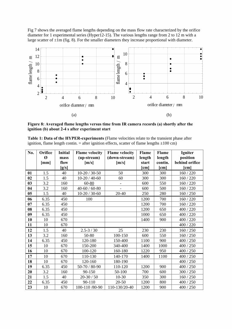
Fig 7 shows the averaged flame lengths depending on the mass flow rate characterized by the orifice diameter for 1 experimental series (Hyper12-15). The various lengths range from 2 to 12 m with a large scatter of ±1m (fig. 8). For the smaller diameters they increase proportional with diameter.
2 4 6 8 102
46
810
1214
orifice diameter ê mm
flam
elen
gth
êm
2 4 6 8 10
4
6
8
10
orifice diameter ê mm
flam
elen
gth
êm
(a) (b)
Figure 8: Averaged flame lengths versus time from IR camera records (a) shortly after the ignition (b) about 2-4 s after experiment start
Table 1: Data of the HYPER-experiments (Flame velocities relate to the transient phase after ignition, flame length contin. = after ignition effects, scatter of flame lengths ±100 cm)
No. Orifice Ø
[mm]
Initial mass flow [g/s]
Flame velocity (up-stream)
[m/s]
Flame velocity (down-stream)
[m/s]
Flame length start [cm]
Flame length contin. [cm]
Igniter position
behind orifice [cm]
01 1.5 40 10-20 / 30-50 50 300 300 160 / 220 02 1.5 40 10-20 / 40-60 60 300 300 160 / 220 03 3.2 160 60-80
- 600 550 160 / 220 04 3.2 160 40-60 / 60-80 - 600 500 160 / 220 05 1.5 40 10-20 / 30-60 20-40 250 280 160 / 250 06 6.35 450 100 1200 700 160 / 220 07 6.35 450 1200 700 160 / 220 08 6.35 450 1200 650 400 / 220 09 6.35 450 1000 650 400 / 220 10 10 670 1400 900 400 / 220 11 10 670 400 / 220 12 1.5 40 2.5-3 / 30 25 230 230 160 / 250 13 3.2 160 50-80 100-150 600 550 160 / 250 14 6.35 450 120-180 150-400 1100 900 400 / 250 15 10 670 150-200 340-400 1400 1000 400 / 250 16 10 670 100-120 160-180 1220 950 400 / 250 17 10 670 110-130 140-170 1400 1100 400 / 250 18 10 670 120-160 180-190 400 / 250 19 6.35 450 50-70 / 80-90 110-120 1200 900 400 / 250 20 3.2 160 90-150 50-100 700 600 300 / 250 21 1.5 40 20-30 / 50 10-30 350 300 160 / 250 22 6.35 450 90-110 20-50 1200 800 400 / 250 23 10 670 100-110 /80-90 110-130/20-40 1200 900 400 / 250
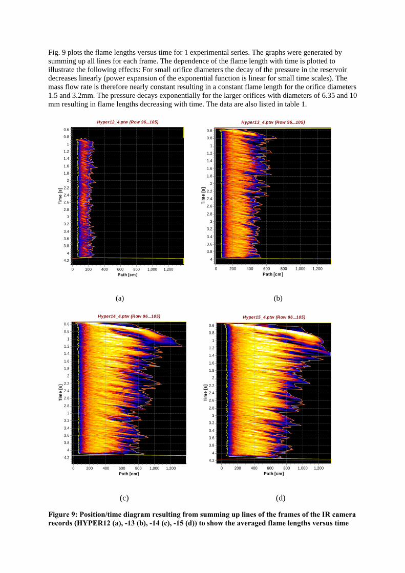
Fig. 9 plots the flame lengths versus time for 1 experimental series. The graphs were generated by summing up all lines for each frame. The dependence of the flame length with time is plotted to illustrate the following effects: For small orifice diameters the decay of the pressure in the reservoir decreases linearly (power expansion of the exponential function is linear for small time scales). The mass flow rate is therefore nearly constant resulting in a constant flame length for the orifice diameters 1.5 and 3.2mm. The pressure decays exponentially for the larger orifices with diameters of 6.35 and 10 mm resulting in flame lengths decreasing with time. The data are also listed in table 1.
Hyper12_4.ptw (Row 96...105) Hyper13_4.ptw (Row 96...105)
Tim
e [s
]
4.2
4
3.8
3.6
3.4
3.2
3
2.8
2.6
2.4
2.2
2
1.8
1.6
1.4
1.2
1
0.8
0.6
Path [cm]1,2001,0008006004002000
Tim
e [s
]
4
3.8
3.6
3.4
3.2
3
2.8
2.6
2.4
2.2
2
1.8
1.6
1.4
1.2
1
0.8
0.6
Path [cm]1,2001,0008006004002000
(a) (b)
Hyper14_4.ptw (Row 96...105) Hyper15_4.ptw (Row 96...105)
Tim
e [s
]
4.2
4
3.8
3.6
3.4
3.2
3
2.8
2.6
2.4
2.2
2
1.8
1.6
1.4
1.2
1
0.8
0.6
Path [cm]1,2001,0008006004002000
Tim
e [s
]
4.2
4
3.8
3.6
3.4
3.2
3
2.8
2.6
2.4
2.2
2
1.8
1.6
1.4
1.2
1
0.8
0.6
Path [cm]1,2001,0008006004002000
(c) (d)
Figure 9: Position/time diagram resulting from summing up lines of the frames of the IR camera records (HYPER12 (a), -13 (b), -14 (c), -15 (d)) to show the averaged flame lengths versus time

The variation of the contour and the brightest zone reflect the fluctuations over the jet end. Fig. 10 shows the various apparent flame velocities in dependence of the flow rate (orifice diameter), the pressure curves in the hydrogen reservoirs were similar. At low flow rates the flame propagation starts with low values below 20-40 m/s and accelerates up-stream. Up-steam and down-stream velocities are similar. At higher flow rates the jets deflagrate at rates close to or above 90-100 m/s. Down-stream velocities are higher of about 40-60 m/s. Such turbulent flame velocities are found in turbulent flows [3, 4], especially if a spherical explosion is assumed for the ignition phase where the laminar flame velocity is already between 10-20 m/s. At the ignition point mixtures mixtgures substantially above the ignition limit have to be assumed which can cause such velocities. Two events were identified where the initial flame propagation reached about 400 m/s down-stream, whereas no significant differences in the flow rates or other jet structures were identified. Table 1 lists also the data scattering.
æ
ææ
æ
ææ
æ
æ
æ
æ æ
æ
æ
ææ
æ
æ
æ
à
àà
à
àà
à
à
àà
àà
à
àà
à
àà
ì
ì
ì ì
ì ìì
ì
ìì
ì
ì
ì
ì
ì
2 4 6 8 100
100
200
300
400
orifice diameter ê mm
flam
evelo
city
êmês
Figure 10: Averaged apparent flame velocities ♦ down-stream, ● up-stream start, ■ up-stream average at the initial phase of the jet combustion
4.0 CONCLUSION
A series of experiments of hydrogen jets were investigated with flow rates of 40 to 670 g/s. The analysis of the results of various visualisation techniques led to the following conclusions:
o Image analysis techniques enable a clear visualisation of hydrogen jets and jet fires, however a quantitative correlation is difficult for large scale experiments
o The un-reacted hydrogen jets form a cone of a half angle of 8-10o, ignition more than doubles it (flame jet)
o Jet lengths and flame lengths increase or decrease with the flow rate in the range tested, they reach 12 m for the investigated experimental setup
o Flame speeds on ignition reach more than 100 m/s, 2 of 23 reached 400 m/s
ACKNOWLEDGEMENTS
The work was funded by the Commission of the European Union, General Directorate XII, contract No: SES6-CT-2004-502630, Hysafe. The collaboration with HSL was excellent.

REFERENCES
1. Lewis, B.; von Elbe, G.; Combustion, flames and explosions of gases; Academic Press Inc., New York 1961
2. Lee J.H.S. and Berman M. Hydrogen combustion and its application to nuclear reactor safety. In G.A. Greene, J.P. Hartnett, T.F. Irvine Jr., and Y.I. Cho, editors, Heat Transfer in Nuclear Reactor Safety, volume 29 of Advances in Heat Transfer, chapter 2, pages 59-123. Academic Press, New York, 1997.
3. S. B. Dorofeev, Process Safety Progress, A flame speed correlation for unconfined gaseous explosions, 26, 2, (2006) 140-149
4. Dorofeev S.B., Efimenko A.A., Kochurko A.S., and Chaivanov B.B. Evaluation of the hydrogen explosions hazard. Nuclear Engineering Design, 148:305-316, 1995
5. Pförtner H. Flame acceleration and pressure build up in free and partially confined hydrogen-air clouds. ICDERS, Ninth Colloquium on the Dynamics of Explosions and Reactive Systems, July 1983.
6. Moore, S.R.; Weinberg, F.J.; Further Studies of the Role of Radiative Ignition in the Propagation of Large Explosions; Proc. R. Soc. Lond. A 409, 1-20 (1987)
7. Kounalakis M. E., Gore J.P., Faeth G. M., Turbulence/radiation interactions in nonpremixed hydrogen/air flames, Twenty-Second Symposium (International) on Combustion, Seattle, WA. USA, August 14-19, 1988
8. Eisenreich, N.; Liehmann, W.: Strahlungsemission von Gasexplosionen, Analysis of Propellants and Explosives, 17th Int. Ann. Conf. of ICT, Karlsruhe, 1986, 82/1-82/13,
9. Kolarik P., Eisenreich N., Untersuchung von Wasserstoff-Luft-Verbrennung bei erhöhten Drücken, 22nd Int. Ann. Conf. of ICT, Karlsruhe, Germany, 1991
10. Eckl, W., Eisenreich, N., Herrmann, M.M., Weindel, M., Emission of radiation from liquefied hydrogen explosions, Chem. Ing. Tech. (1995) 67 (8), 1015-17
11. Weiser V., Roth E., Kelzenberg S., Eckl W., Eisenreich N., and Langer G., Measuring and modelling unsteady radiation of hydrogen combustion. Paper presented at the First International Conference on Hydrogen Safety, Pisa, Italy, 8-10 September 2005
12. Raffel M., Willert C., Kompenhans J. (1998): Particle Image Velocimetry, Springer-Verlag Berlin Heidelberg.
13. Brock, A., Deimling, L., Direkte Kreuzkorrelation zur hochauflösenden PIV-Auswertung von Wirbelstrukturen, 30th Int. Ann. Conference of ICT, June 29th- July 2nd, 1999. Pfinztal: Proceedings p103/1-p103/11
14. Raffel M., Richard H., Meier G.E.A.: On the applicability of Background Oriented Optical Tomography, Experiments in Fluid, 2000, 447-481.
15. H. Richard, M. Raffel, M. Rein, J. Kompenhans, G.E.A. Meier, Demonstration of the applicability of a Background Oriented Schlieren (BOS) method 10th Symposium of Applications Laser Techniques to Fluid, 2000.
16. Keßler, A., Ehrhardt, W., Langer, G., Hydrogen detection: visualisation of hydrogen using non invasive optical schlieren technique BOS. Paper presented at the 1st Int. Conf. Hydrogen Safety, Pisa, Italy, 8-10 September 2005.
17. Otsuka T., Saitoh H., Mizutani T.,Morimoto K., Yoshikawa N., Hazard evaluation of hydrogen-air deflagrations with flame propagation velocity measurement by image velocimetry using brightness subtraction, J. Loss Prevention, 20 (2007) 427-432
18. Ziliani F., Cavallaro A., Image Analysis for Video Surveillance Based on Spatial Regularization of a Statistical Model-Based Change Detection, Real-Time Imaging, 7, (2001) 389-399
19. Abramovich G. N., The Theory of Turbulent Jets, MIT Press, Massachusetts (1963) 20. Schmidt E, Ausströmen von Gasen aus Behältern hohen Innendrucks, Chem. Ing. Tech. 37(1965)3 21. Glass M.W., Far-Field Dispersal Modeling for Fuel-Air-Explosive Devices, Sandia Nat. Labs.,
Albuquerque, Report SAND90-0528 (1990)