vol.13, november.2014 issn 2354-7065 - isomase.orgisomase.org/jomase/vol.13 nov 2014/vol-13.pdf ·...
TRANSCRIPT
ISSN 2354-7065Vol.13, November.2014
Journal of Ocean, Mechanical and Aerospace -Science and Engineering-
Vol.13: November 2014
ISOMAse
International Society of Ocean, Mechanical and Aerospace -Scientists and Engineers-
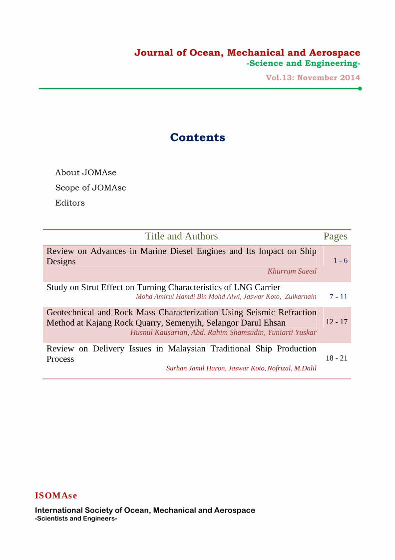
Contents
About JOMAse
Scope of JOMAse
Editors
Title and Authors PagesReview on Advances in Marine Diesel Engines and Its Impact on Ship Designs
Khurram Saeed
1 - 6
Study on Strut Effect on Turning Characteristics of LNG Carrier Mohd Amirul Hamdi Bin Mohd Alwi, Jaswar Koto, Zulkarnain
7 - 11
Geotechnical and Rock Mass Characterization Using Seismic Refraction Method at Kajang Rock Quarry, Semenyih, Selangor Darul Ehsan
Husnul Kausarian, Abd. Rahim Shamsudin, Yuniarti Yuskar
12 - 17
Review on Delivery Issues in Malaysian Traditional Ship Production Process
Surhan Jamil Haron, Jaswar Koto, Nofrizal, M.Dalil
18 - 21
Journal of Ocean, Mechanical and Aerospace -Science and Engineering-
Vol.12: October 2014
ISOMAse
International Society of Ocean, Mechanical and Aerospace -Scientists and Engineers-
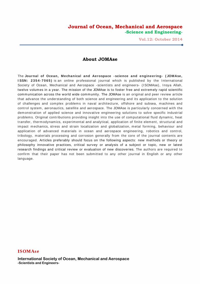
About JOMAse
The Journal of Ocean, Mechanical and Aerospace -science and engineering- (JOMAse, ISSN: 2354-7065) is an online professional journal which is published by the International Society of Ocean, Mechanical and Aerospace -scientists and engineers- (ISOMAse), Insya Allah, twelve volumes in a year. The mission of the JOMAse is to foster free and extremely rapid scientific communication across the world wide community. The JOMAse is an original and peer review article that advance the understanding of both science and engineering and its application to the solution of challenges and complex problems in naval architecture, offshore and subsea, machines and control system, aeronautics, satellite and aerospace. The JOMAse is particularly concerned with the demonstration of applied science and innovative engineering solutions to solve specific industrial problems. Original contributions providing insight into the use of computational fluid dynamic, heat transfer, thermodynamics, experimental and analytical, application of finite element, structural and impact mechanics, stress and strain localization and globalization, metal forming, behaviour and application of advanced materials in ocean and aerospace engineering, robotics and control, tribology, materials processing and corrosion generally from the core of the journal contents are encouraged. Articles preferably should focus on the following aspects: new methods or theory or philosophy innovative practices, critical survey or analysis of a subject or topic, new or latest research findings and critical review or evaluation of new discoveries. The authors are required to confirm that their paper has not been submitted to any other journal in English or any other language.

Journal of Ocean, Mechanical and Aerospace -Science and Engineering-
Vol.12: October 2014
ISOMAse
International Society of Ocean, Mechanical and Aerospace -Scientists and Engineers-
Scope of JOMAse
The JOMAse welcomes manuscript submissions from academicians, scholars, and practitioners for possible publication from all over the world that meets the general criteria of significance and educational excellence. The scope of the journal is as follows:
• Environment and Safety • Renewable Energy • Naval Architecture and Offshore Engineering • Computational and Experimental Mechanics • Hydrodynamic and Aerodynamics • Noise and Vibration • Aeronautics and Satellite • Engineering Materials and Corrosion • Fluids Mechanics Engineering • Stress and Structural Modeling • Manufacturing and Industrial Engineering • Robotics and Control • Heat Transfer and Thermal • Power Plant Engineering • Risk and Reliability • Case studies and Critical reviews
The International Society of Ocean, Mechanical and Aerospace –science and engineering is inviting you to submit your manuscript(s) to [email protected] for publication. Our objective is to inform authors of the decision on their manuscript(s) within 2 weeks of submission. Following acceptance, a paper will normally be published in the next online issue.
Journal of Ocean, Mechanical and Aerospace -Science and Engineering-
Vol.12: October 2014
ISOMAse
International Society of Ocean, Mechanical and Aerospace -Scientists and Engineers-
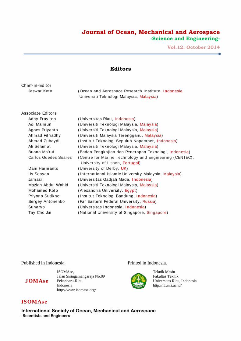
Editors
Chief-in-Editor
Jaswar Koto (Ocean and Aerospace Research Institute, Indonesia Universiti Teknologi Malaysia, Malaysia)
Associate Editors
Adhy Prayitno (Universitas Riau, Indonesia) Adi Maimun (Universiti Teknologi Malaysia, Malaysia) Agoes Priyanto (Universiti Teknologi Malaysia, Malaysia) Ahmad Fitriadhy (Universiti Malaysia Terengganu, Malaysia) Ahmad Zubaydi (Institut Teknologi Sepuluh Nopember, Indonesia) Ali Selamat (Universiti Teknologi Malaysia, Malaysia) Buana Ma’ruf (Badan Pengkajian dan Penerapan Teknologi, Indonesia) Carlos Guedes Soares (Centre for Marine Technology and Engineering (CENTEC), University of Lisbon, Portugal) Dani Harmanto (University of Derby, UK) Iis Sopyan (International Islamic University Malaysia, Malaysia) Jamasri (Universitas Gadjah Mada, Indonesia) Mazlan Abdul Wahid (Universiti Teknologi Malaysia, Malaysia) Mohamed Kotb (Alexandria University, Egypt) Priyono Sutikno (Institut Teknologi Bandung, Indonesia) Sergey Antonenko (Far Eastern Federal University, Russia) Sunaryo (Universitas Indonesia, Indonesia) Tay Cho Jui (National University of Singapore, Singapore)
Published in Indonesia.
JOMAse
ISOMAse, Jalan Sisingamangaraja No.89 Pekanbaru-Riau Indonesia http://www.isomase.org/
Printed in Indonesia.
Teknik Mesin Fakultas Teknik Universitas Riau, Indonesia http://ft.unri.ac.id/
Journal of Ocean, Mechanical and Aerospace -Science and Engineering-, Vol.13
November 20, 2014
1 Published by International Society of Ocean, Mechanical and Aerospace Scientists and Engineers
Review on Advances in Marine Diesel Engines and Its Impact on Ship Designs
Khurram Saeed,a,*
a) Faculty of Mechanical Engineering, Universiti Teknologi Malaysia, 81310 Skudai, Johor Bahru *Corresponding author: [email protected] Paper History Received: 16-July-2014 Received in revised form: 20-July-2014 Accepted: 14-November-2014 ABSTRACT The aim of this paper is to take full advantage of the waste heat which is being dissipated into the surrounding atmosphere from a diesel engine in which 25.5% by the exhaust gases, 14.1% and 6.3% by air cooler and jacket water correspondingly. A waste heat recovery system is used to recover exhaust energy, waste heat from the coolant system, and released heat from turbocharged air in the intercooler of a diesel engine. By using waste heat from the engines, the efficiency of the combustion process can be significantly improved, manufacturers claim that savings in fuel consumption and fuel costs can be up to 10%.Waste Heat Recovery System is one of the foremost energy reduction system to make a more efficient usage of fuels to achieve environmental improvement as well as saving the amount of energy which is being wasted from the Main engine power. The recovered energy of 11.4% is converted into mechanical energy to run the electrical generator to meet the power demands onboard ship and some part of the energy is being utilized on the steam service system, which ultimately is going to impact the designs of the ship. KEY WORDS: Waste Heat, Waste Heat Recovery System, Efficiency. NOMENCLATURE
Waste Heat Recovery
Power Turbine and Generator Steam Turbine and Generator
Modular Arrangement Concept Maersk Maritime Technology
1.0 INTRODUCTION Today the greater part of the Prime Movers (Propulsion arrangement) and auxiliary plants of sea going vessels are Diesel Engines. High Pressure combustion engines are still the basic propeller for the ships due to the highest efficiency as compared to the other Diesel engines. Whilst enrouting, Diesel engines onboard have an efficiency of about 60% and the remaining amount of energy is being dissipated into the surrounding atmosphere in terms of exhaust gas and jacket water [1].However, a lot of work is being carried out and is in the development towards a better refinement of the thermal efficiency by enhancing the layout of the engine to achieve a better fuel consumption. A high end substitute approach in surpassing the overall energy efficiency is to reproduce and retrieving the 'Waste Heat'.
Waste Heat Recovery System is one of the foremost energy reduction systems to make a more efficient usage of fuels to achieve environmental improvement as well as saving the amount of energy which is being wasted from the Main engine power. It enables ship-owners to make better use of existing energy within the vessel’s full combustion cycle. By using waste heat from the engines, the efficiency of the combustion process can be significantly improved, manufacturers claim that savings in fuel consumption and fuel costs can be up to 10%.It is easier to make use of the firm waste heat on the ships as compared to that of the automobile. Furthermore, it can provide both heat source (waste heat) and cooling source (sea water).
The world's merchant fleet represents almost 80% of all the vessels ordered each year. Among them 85% will be having two stroke engines for propulsion with the remaining having four stroke engines. The energy regaining from the engines is relying

Journal of Ocean, Mechanical and Aerospace -Science and Engineering-, Vol.13
November 20, 2014
2 Published by International Society of Ocean, Mechanical and Aerospace Scientists and Engineers
up to a greater degree on the main engine load and ambient temperatures. Scappin assessed the performance of a two stoke diesel engine by means of an energy balance. He investigated the energy balance and used combined cycles to reclaim energy from other waste heat sources [2].
Therefore, to apprehend and reuse the waste heat onboard is an emission free process for the costly fuel which is purchased and then being used for the propulsion system. Waste heat recovery cannot be used only as an environmental control measure but also for the boosting the efficiency of fuel consumption.
A lot of number solutions have been proposed to generate power, electricity and heating from the waste heat sources. As the flow rate of waste heat source onboard ships is in a considerable large amount, so the potential for waste heat recovery is particularly promising. 2.0 WASTE HEAT RECOVERY SYSTEM WORKING 2.1 Analysis of Energy Balance Prior to research on recovering waste heat from the diesel engine, the analysis of the energy balance should be carried out to find out the possibilities of waste heat recovery. A study carried out on a two stroke diesel engine of MAN B and W Diesel with an approximation that 25.5% of the released energy is wasted from the exhaust as shown in Figure.1 at ISO ambient reference conditions at 100SMCR, and 16.5% and 5.2% is wasted from the air cooler and jacket water respectively. Assuming the average operation in service at 85SMCR is 58.344KW in 280 days a year, 24 hours per day, 31,726 tonnes of heavy fuel will be lost through the exhaust gas, air cooler and jacket water. Figure.1 shows that for the engine with the combination of WHRS the total efficiency will increase to about 55%.
Figure 1: Heat Balance Diagram of a nominally rated 12S98ME-C9.2 engine.
Another study carried out by an another engine manufacturer Wartsila on a two stroke diesel engine has discovered that around 25.4% of the energy is being wasted from the exhaust and 12.9% and 6.2% is from the air cooler and jacket water appropriately. The possibilities are illustrated for Wartsila 12RT-flex96C engines as shown in Figure.2 with and without the waste heat recovery system showing in this case a 54.9% gain in overall efficiency with the waste heat recovery system.
Figure 2: Heat Balance Diagram of a nominally rated 12RT-flex96C engine. 2.2 Working Principle Modern marine engines such as the super long-stroke MAN B&W S90ME-C9 type or the Wartsila RT-flex series, uses the energy from the exhaust gases to increase the power that the engine can produce. In a typical arrangement, the gases leaving the engine are passed through a turbocharger, which uses the energy of the gas to spin a turbine that forms part of an air compressor. This compressor increases the mass of air that flows into the engine, enabling large quantities of fuel to be burnt more efficiently.
However, the energy of the exhaust gas can be used in other ways. First, it can be used to spin a power turbine that produces electricity. Secondly, it can be used to generate steam which can then be used in a gas-fired boiler to meet onboard heat demands. Systems that achieve either or both of the above are labeled as Waste Heat Recovery systems. Waste Heat Recovery systems are typically located in the main engine room.
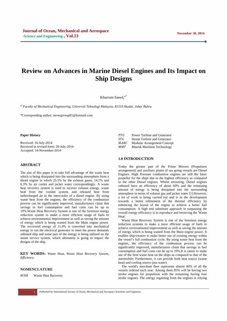
As per[6] MAN B and W the principle of the Waste heat recovery system for the low speed diesel engine is that part of the exhaust gas flow is bypassed the main engine turbochargers through an exhaust gas bypass. As a result, the total amount of intake air and exhaust gas is reduced. The reduction of the intake air amount and the exhaust gas amount results in an increased exhaust gas temperature after the main engine turbochargers and exhaust gas bypass. This means an increase in the maximum obtainable steam production power for the exhaust gas fired boiler that is the steam, which can be used in a steam turbine for electricity production. Also, the revised pressure drop in the exhaust gas bypass, which is part of the WHRS, can be utilized to produce electricity by applying a power turbine. The main WHRS principles are shown in Figure. 3. As mentioned before, a WHRS consist of different components, and may wary as a stand-alone installation or a combined installation.
Choosing a system for a project depends on the power demand on board the ship (electrical load at sea), the ship’s running profile (hours at different main engine loads at sea). A very important part of selecting the best WHRS for a ship project is choosing the best suited propulsion power and rpm for the ship, biggest possible propeller, so as to ensure the lowest possible fuel consumption for the basic performance of the ship.
In many cases, WHRS will be able to supply the total electricity need of the ship as a standalone power source, but it can also run in parallel with a shaft generator, shaft motor and auxiliary diesel generating sets. This type of advanced power system requires an advanced power management system.
Journal of Ocean, Mechanical and Aerospace -Science and Engineering-, Vol.13
November 20, 2014
3 Published by International Society of Ocean, Mechanical and Aerospace Scientists and Engineers
Figure 3: Waste Heat Recovery System Principle 3.0 WASTE HEAT RECOVERY INSTALLATION OPTIONS Today several different WHRS are readily available. Depending on the level of complexity acceptable to the owner and shipyard and the actual electrical power consumption onboard, it is possible to choose between the following systems: • ST-PT: Steam Turbine-Power Turbine generator. Power
turbine and steam turbine generator with single or dual pressure steam turbine.
• STG: Steam Turbine Generator unit (Stand-alone, single or Dual steam pressure).
• PTG: Power Turbine Generator Power turbine stand-alone generator.
3.1 Power Turbine and Generator (PTG) The simplest and cheapest system consists of an exhaust gas turbine (also called a power turbine) installed in the exhaust gas bypass, and a generator that converts power from the power turbine to electricity onboard the ship as shown in Figure. 4.
Figure 4: Schematic Diagram of the TCS-PTG System
The power turbine is driven by part of the exhaust gas flow which bypasses the turbochargers. The power turbine produces extra output power for electric power production, which depends on the bypassed exhaust gas flow amount. The TCS-PTG WHRS solution offers both standalone and parallel running electric power sourcing for the ship.
The exhaust gas bypass valve will be closed at an engine power lower than about 50% SMCR, where the engine will run with the same high efficiency as for a normal MAN B and W low speed two strokes engine. 3.2 Steam Turbine Generator (STG) The second system builds on the principle exhaust gas by pass and, thereby, increasing the exhaust gas temperature before the
boiler without using a power turbine. When applying the steam turbine (ST) as a stand-alone solution, the exhaust gas bypass stream is mixed with the exhaust outlet from the turbocharger(s), increasing the exhaust gas temperature before the boiler inlet.
When part of the exhaust gas flow is by passed the turbocharger, the total amount of air and gas will be reduced, and the exhaust gas temperature after the turbo charger and bypass will increase. This will increase the obtained able steam production power for the exhaust gas fired boiler. By installing a steam turbine (often called a turbo generator), the obtained able steam production from the exhaust boiler system can be used for electric power production. The steam turbine is installed on a common bedplate with the generator in the same manner as the power turbine and the generator.
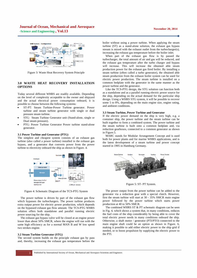
Like the TCS-PTG design, the STG solution can function both as a standalone and as a parallel running electric power source for the ship, depending on the actual demand for the particular ship design. Using a WHRS STG system, it will be possible to recover some 5 to 8%, depending on the main engine size, engine rating, and ambient conditions. 3.3 Steam Turbine, Power Turbine and Generator If the electric power demand on the ship is very high, e.g. a container ship, the power turbine and the steam turbine can be built together to form a combined system. The power turbine and the steam turbine is built onto a common bedplate and, via reduction gearboxes, connected to a common generator as shown in Figure.5.
MARC stands for Modular Arrangement Concept and is used both for power plants and for marine WHRS applications, and is the latest development of a steam turbine and power concept started in 1905 in Hamburg Germany.
Figure 5: ST- PT System.
The power output from the power turbine can be added to the generator via a reduction gear with a special clutch. However, first the steam turbine will start at 30 - 35% SMCR main engine power followed by the power turbine which starts power production at 40 to 50% SMCR.
The combined WHRS ST & PT schematic diagram can be seen in Fig. 4, which shows a system that, in many conditions, reduces the fuel costs of the ship considerably by being able to cover the total electric power needs in many conditions onboard the ship. Otherwise, a shaft motor / generator (PTI/PTO) connected to the main engine shaft could be an option as shown in Figure. 6, making it possible to add either electric power to the ship grid if needed, or to boost propulsion by supplying the electric power to the PTI.
Journal of Ocean, Mechanical and Aerospace -Science and Engineering-, Vol.13
November 20, 2014
4 Published by International Society of Ocean, Mechanical and Aerospace Scientists and Engineers
Selecting the full WHRS, combining both steam and power turbines, some8-11% power can be recovered, depending on the main engine size, engine rating and ambient conditions.
Figure 6: Schematic Diagram for the WHRS ST-PT System 4.0 CASE STUDY 4.1 Maersk Maersk Maritime Technology has been an early pioneer with use of waste heat recovery technology. Maersk Maritime Technology (MMT) has previously stated that high fuel efficiency can be expected from installing waste heat recovery technology, compared to other systems, onboard vessels.
According to the company, currently 32 Maersk container ships in total have been fitted with the technology since the 1980s, achieving reductions in fuel costs of 9%. Since 2008, WHR has been installed on all containerships that have been ordered and will be on the ten new Triple E ships currently under construction. The first installation of the high efficiency WHR plant entered service in the 7500 TEU container ship Gurdun Maersk in June 2005. It successfully confirmed the benefits of the new WHR plant concept. During sea trials and in operation, the performance of the WHR plant exceeded expectations.
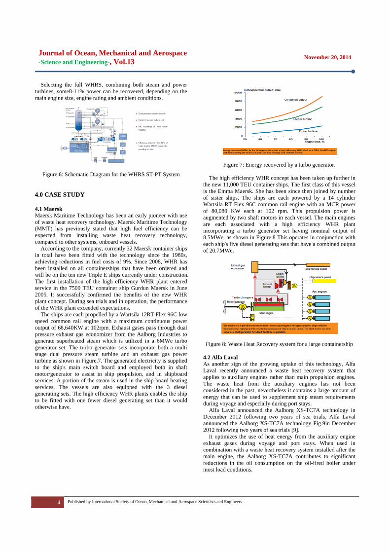
The ships are each propelled by a Wartsila 12RT Flex 96C low speed common rail engine with a maximum continuous power output of 68,640KW at 102rpm. Exhaust gases pass through dual pressure exhaust gas economizer from the Aalborg Industries to generate superheated steam which is utilized in a 6MWe turbo generator set. The turbo generator sets incorporate both a multi stage dual pressure steam turbine and an exhaust gas power turbine as shown in Figure.7. The generated electricity is supplied to the ship's main switch board and employed both in shaft motor/generator to assist in ship propulsion, and in shipboard services. A portion of the steam is used in the ship board heating services. The vessels are also equipped with the 3 diesel generating sets. The high efficiency WHR plants enables the ship to be fitted with one fewer diesel generating set than it would otherwise have.
Figure 7: Energy recovered by a turbo generator.
The high efficiency WHR concept has been taken up further in the new 11,000 TEU container ships. The first class of this vessel is the Emma Maersk. She has been since then joined by number of sister ships. The ships are each powered by a 14 cylinder Wartsila RT Flex 96C common rail engine with an MCR power of 80,080 KW each at 102 rpm. This propulsion power is augmented by two shaft motors in each vessel. The main engines are each associated with a high efficiency WHR plant incorporating a turbo generator set having nominal output of 8.5MWe. as shown in Figure.8 This operates in conjunction with each ship's five diesel generating sets that have a combined output of 20.7MWe.
Figure 8: Waste Heat Recovery system for a large containership
4.2 Alfa Laval As another sign of the growing uptake of this technology, Alfa Laval recently announced a waste heat recovery system that applies to auxiliary engines rather than main propulsion engines. The waste heat from the auxiliary engines has not been considered in the past, nevertheless it contains a large amount of energy that can be used to supplement ship steam requirements during voyage and especially during port stays.
Alfa Laval announced the Aalborg XS-TC7A technology in December 2012 following two years of sea trials. Alfa Laval announced the Aalborg XS-TC7A technology Fig.9in December 2012 following two years of sea trials [9].
It optimizes the use of heat energy from the auxiliary engine exhaust gases during voyage and port stays. When used in combination with a waste heat recovery system installed after the main engine, the Aalborg XS-TC7A contributes to significant reductions in the oil consumption on the oil-fired boiler under most load conditions.
Journal of Ocean, Mechanical and Aerospace -Science and Engineering-, Vol.13
November 20, 2014
5 Published by International Society of Ocean, Mechanical and Aerospace Scientists and Engineers
Unlike the continual operation of the main engine during oceangoing voyages, the operation of the auxiliary engines varies. The Aalborg XS-TC7A, therefore, has been developed as a customized solution focused on generating energy under varying load conditions. To ensure the most advantageous design, the Aalborg XS-TC7A will be specially tailored to the individual ship and engine design with due consideration to the existing uptake back pressure and other critical factors.
Figure 9: Aalborg XS - TC7A WHR System.
The economizer features an optimized and specialized convection part, which augments heat transfer caused by increased turbulence at the exhaust gas boundary layer. This provides the capability to increase steam production while reducing the weight and maintenance cost of the Aalborg XS-TC7A compared to other WHR systems. 5.0 ECONOMICAL BENEFIT The economic benefits of the high efficiency waste heat recovery system can be illustrated as shown in figure. 10, by a case of a container ship powered by 12 cylinder Wartsila RT-Flex96C engine. In the case, the engine would operate at an average of 85% load for about 6500 hours a year on bunkers costing US$ 250/tonne, with an average total electrical load of 5350KW,including refer containers. The annual operating costs for the main and auxiliary engines, including fuel, maintenance and lubricating oil, would be US$ 19.54 million without a waste heat recovery plant and US$ 17.29 million with a high efficiency waste heat recovery plant.
Figure 10: Economical Benefit of a WHR Plant.
There would thus be annual savings of US$ 2.25 million. If the
bunker price increased from US$ 250 to US$ 400/tonne, then the annual savings would increase to about 3.48 million. The complete high efficiency waste heat recovery plant and its installation would call for an investment cost of about US$ 9.5
million. This would thus have an expected payback time of less than five years. 6.0 NEW WASTE HEAT RECOVERY ON HORIZON An innovative new waste heat recovery system is also set to enter the marine market. GE Marine announced a new licensing agreement with Echogen Power Systems LLC that will see the Echogen system sold to commercial and military marine vessels worldwide.
The Echogen system is different to traditional systems due to its use of supercritical carbon dioxide (CO2), heated CO2 that has properties of both a liquid and a gas, as its working fluid, rather than steam. This is said to make the system more compact and economical than a traditional waste heat recovery system.
As per Echogen Fig. 11, the CO2 heat engine will mainly be comprising of five main components, namely exhaust and recuperator heat exchangers, condenser, system pump and power turbine. Auxiliary components involve valves and sensors which provides the system monitoring and control. Heat energy is introduced into the sCO2 power cycle by the exhaust heat exchanger being mounted into the exhaust stack from a diesel engine. The available technology converts energy that traditionally gets exhausted out of a stack into useful power allows the overall system efficiency to increase by up to 30%. The product can operate efficiently in a broad range of exhaust temperatures, and the working fluid can be expanded for cooling or a combination of power and cooling.
Figure 11: Supercritical CO2 Power Cycle.
7.0 CONCLUSION The overall concept of this paper is to provide ways of recovering waste heat from the exhaust gases of the diesel engine. The engine manufacturer Wartsila states that their high-efficiency WHR system which uses both power and steam turbines could cut exhaust emissions and deliver fuel savings of up to 12%, with a return on investment of less than 5 years. The engine manufacturer MAN Diesel and Turbo is more conservative in their claims. They suggest energy savings of 4-11% for their WHR systems, depending on a range of factors such as the operational profile of the ship, electricity demand whilst at sea, and the power level of the engine.
It must be remembered that the modern age, low speed engines are very highly developed and there is little potential for achieving significant savings in fuel consumption, and thereby

Journal of Ocean, Mechanical and Aerospace -Science and Engineering-, Vol.13
November 20, 2014
6 Published by International Society of Ocean, Mechanical and Aerospace Scientists and Engineers
reducing CO2 by engine developments alone. Yet major improvements can be gained by using proven technology and hardware through applying the high efficiency waste heat recovery plant. ACKNOWLEDGEMENT I would like to convey a great appreciation to Ocean and Aerospace Engineering Research Institute, Indonesia for supporting this research. REFERENCES
1. Shu, G., Liang, Y., Wei, H., Tian, H., Zhao, J., & Liu, L. A review of waste heat recovery on two-stroke IC engine aboard ships.Renewable and Sustainable Energy Reviews
2. Scappin F, Stefansson SH, Haglind F, Andreasen A, LarsenU. Validation of a zero-dimensional model for prediction of NOx and engine performance for electronically controlled marine two-stroke diesel engines. Applied Thermal Engineering 2012; 37: 344 – 352.
3. He M, Zhang X, Zeng K, Gao K. A Combined Thermodynamic Cycle Used for Waste Heat Recovery of Internal Combustion Engine. Energy 2011; 36: 6821–6829.
4. Shu, G., Liang, Y., Wei, H., Tian, H., Zhoa, J., & Liu, L. A Review of Waste Heat Recovery on Two-Stroke IC Engine aboard Ships. Renewable and Sustainable Energy Reviews. Retrieved December 12, 2012
5. Eyringer V, K¨ohler HW,Lauer A, Lemper B. Emissions From International Shipping: Impact of Future Technologies on Scenarios Until 2050. Journal of Geophysical Research2005; 110: D17306.
6. Ramesh, U., and Kalyani, T. Improving the Efficiency of Marine Power Plan Using Stirling Engine in Waste Heat Recovery Systems. International Journal of innovative research and development
Journal of Ocean, Mechanical and Aerospace -Science and Engineering-, Vol.13
November 20, 2014
7 Published by International Society of Ocean, Mechanical and Aerospace Scientists and Engineers
Study on Strut Effect on Turning Characteristics of LNG Carrier
Mohd Amirul Hamdi Bin Mohd Alwi,a Jaswar Koto,a, b,* and Zulkarnain,b
a)Department of Aeronautics, Automotive and Ocean Engineering,Mechanical Engineering, Universiti Teknologi Malaysia b)Ocean and Aerospace Engineering Research Institute, Indonesia *Corresponding author: [email protected] and [email protected] Paper History Received: 10-November-2014 Received in revised form: 15-November-2014 Accepted: 19-November-2014 ABSTRACT There are many types of propulsion system used to propel the ship. One of them is podded propulsion system. Up to date, there is still no LNG carrier that was installed with this kind of propulsion system. The idea of installing podded propulsion system onto LNG carrier is till at design and development stage. This paper presents about the study on effect of changing the size of strut of podded propulsor to the turning characteristic of an LNG carrier named Tenaga Satu. The manoeuvring performance of this ship can be predicted by using numerical simulation method. This study is mainly focussing on modifying and developing mathematical model to simulate the turning characteristic of this LNG carrier. Three designs of pod propulsor with different strut length have been made to evaluate the effect to the turning characteristic. KEY WORDS: Podded Propulsion; Turning Characteristics; LNG Carrier; Manoeuvring; Mathematical Model; Numerical Simulation. NOMENCLATURE
International Maritime Organization Liquefied Natural Gas Longitudinal Center Buoyancy
1.0 INTRODUCTION According to the IMO “Standards for Ship Manoeuvrability”, manoeuvring performance of a ship should be predicted during the preliminary design stage. There are two methods that were widely used to predict the ship manoeuvrability. The first method is free-running model test, and the second one is by applying computer simulation using the mathematical method. [1] In this study, mathematical model method was applied. Before applying this method, it is a must to prepare the modelling of the equations describing the manoeuvring motions first. Then, computer simulation is carried out to determine manoeuvring characteristics by the means of the mathematical model.
For this project, an existing LNG carrier named “Tenaga Satu” was chosen. The problem with TenagaSatu is it is a ship that was installed with conventional propulsion system where it uses the common configuration of main engine, rudder, and propeller as it propulsion system but this study requires an LNG carrier with podded propulsion system. Since there is still no LNG carrier that is installed with podded propulsion system in operation today, it is considerable to select this Tenaga Satu LNG carrier for this study and all the prediction on manoeuvring and turning ability will be based on this ship.
Table 1: Technical Information of Tenaga Satu LNG Carrier. Principle Dimension
Length overall (Loa) (m) 289.119 Length water line (Lwl) (m) 277.653 Length between perpendicular (Lpp) (m) 266 Breadth moulded (Bm) (m) 41.6 Depth moulded (Dm) (m) 25.448
Hydrostatic coefficient Block Coefficient (Cb) 0.726
Journal of Ocean, Mechanical and Aerospace -Science and Engineering-, Vol.13
November 20, 2014
8 Published by International Society of Ocean, Mechanical and Aerospace Scientists and Engineers
Prismatic Coefficient (Cp) 0.734 Prismatic Coefficient at after (Cpa) 0.684 MidshipCoefficient (Cm) 0.989 Water Plane Coefficient (Cwp) 0.801
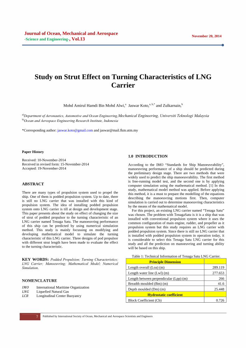
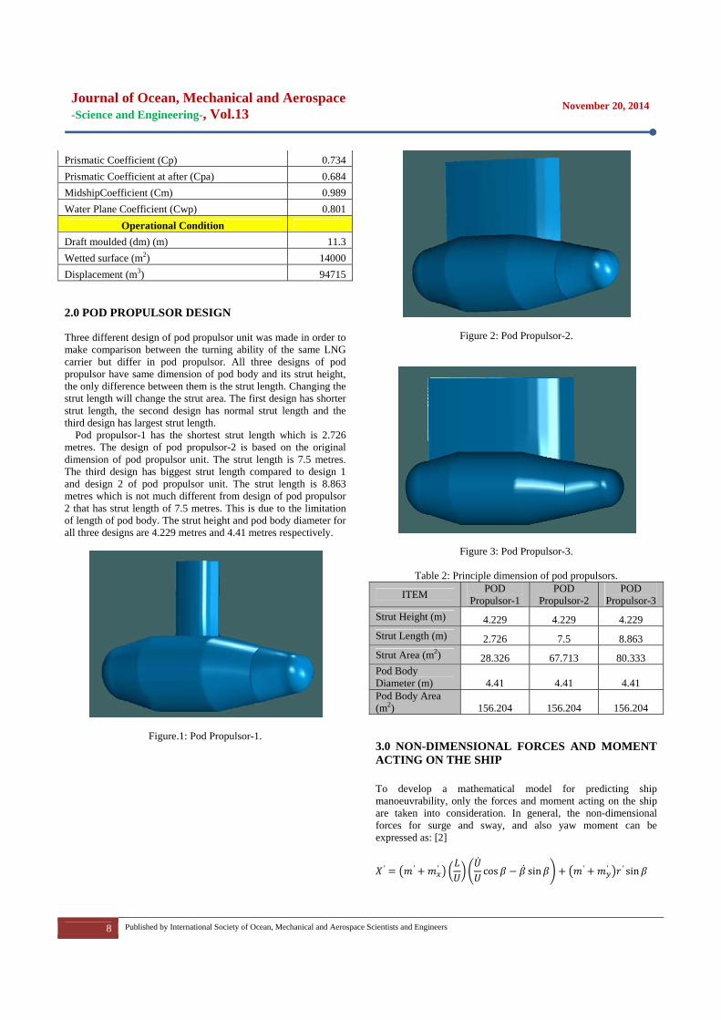
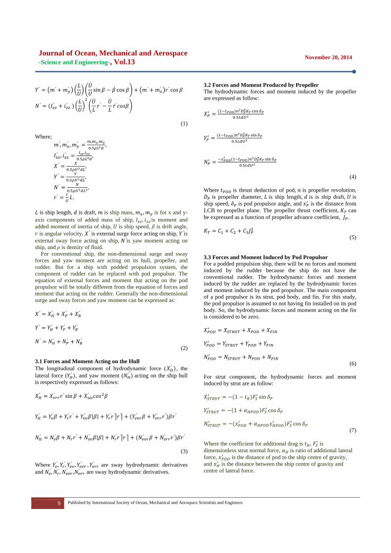
Operational Condition Draft moulded (dm) (m) 11.3 Wetted surface (m2) 14000 Displacement (m3) 94715 2.0 POD PROPULSOR DESIGN Three different design of pod propulsor unit was made in order to make comparison between the turning ability of the same LNG carrier but differ in pod propulsor. All three designs of pod propulsor have same dimension of pod body and its strut height, the only difference between them is the strut length. Changing the strut length will change the strut area. The first design has shorter strut length, the second design has normal strut length and the third design has largest strut length.
Pod propulsor-1 has the shortest strut length which is 2.726 metres. The design of pod propulsor-2 is based on the original dimension of pod propulsor unit. The strut length is 7.5 metres. The third design has biggest strut length compared to design 1 and design 2 of pod propulsor unit. The strut length is 8.863 metres which is not much different from design of pod propulsor 2 that has strut length of 7.5 metres. This is due to the limitation of length of pod body. The strut height and pod body diameter for all three designs are 4.229 metres and 4.41 metres respectively.
Figure.1: Pod Propulsor-1.
Figure 2: Pod Propulsor-2.
Figure 3: Pod Propulsor-3.
Table 2: Principle dimension of pod propulsors.
ITEM POD Propulsor-1
POD Propulsor-2
POD Propulsor-3
Strut Height (m) 4.229 4.229 4.229 Strut Length (m) 2.726 7.5 8.863 Strut Area (m2) 28.326 67.713 80.333 Pod Body Diameter (m) 4.41 4.41 4.41 Pod Body Area (m2) 156.204 156.204 156.204 3.0 NON-DIMENSIONAL FORCES AND MOMENT ACTING ON THE SHIP To develop a mathematical model for predicting ship manoeuvrability, only the forces and moment acting on the ship are taken into consideration. In general, the non-dimensional forces for surge and sway, and also yaw moment can be expressed as: [2] ′ ′ ′ cos sin ′ ′ ′ sin
Journal of Ocean, Mechanical and Aerospace -Science and Engineering-, Vol.13
November 20, 2014
9 Published by International Society of Ocean, Mechanical and Aerospace Scientists and Engineers
′ ′ ′ sin cos ′ ′ ′ cos
′ ′ ′ ′ ′
(1)
Where;
′, ′ , ′ , ,.
, ′ , ′ ,
.,
′.
, ′
.,
′.
, ′ .
is ship length, is draft, is ship mass, , is for x and y-
axis components of added mass of ship, , is moment and added moment of inertia of ship, is ship speed, β is drift angle,
is angular velocity, ′ is external surge force acting on ship, ′is external sway force acting on ship, ′is yaw moment acting on ship, and ρ is density of fluid.
For conventional ship, the non-dimensional surge and sway forces and yaw moment are acting on its hull, propeller, and rudder. But for a ship with podded propulsion system, the component of rudder can be replaced with pod propulsor. The equation of external forces and moment that acting on the pod propulsor will be totally different from the equation of forces and moment that acting on the rudder. Generally the non-dimensional surge and sway forces and yaw moment can be expressed as:
′ ′ ′ ′
′ ′ ′ ′
′ ′ ′ ′
(2) 3.1 Forces and Moment Acting on the Hull The longitudinal component of hydrodynamic force ( ′ , the lateral force ( ′ , and yaw moment ( ′ acting on the ship hull is respectively expressed as follows:
′ ′ ′ sin ′
′ ′ ′ ′ ′ | | ′ ′ ′ ′ ′ ′ ′
′ ′ ′ ′ | | ′ ′ ′ ′ ′ ′ ′
(3)
Where ′ , ′ , ′ , ′ , ′ are sway hydrodynamic derivatives and ′ , ′ , ′ , ′ are sway hydrodynamic derivatives.
3.2 Forces and Moment Produced by Propeller The hydrodynamic forces and moment induced by the propeller are expressed as follow:
.
.
.
(4)
Where is thrust deduction of pod, is propeller revolution,
is propeller diameter, is ship length, is is ship draft, is ship speed, is pod propulsor angle, and is the distance from LCB to propeller plane. The propeller thrust coefficient, can be expressed as a function of propeller advance coefficient, .
(5) 3.3 Forces and Moment Induced by Pod PropulsorFor a podded propulsion ship, there will be no forces and moment induced by the rudder because the ship do not have the conventional rudder. The hydrodynamic forces and moment induced by the rudder are replaced by the hydrodynamic forces and moment induced by the pod propulsor. The main component of a pod propulsor is its strut, pod body, and fin. For this study, the pod propulsor is assumed to not having fin installed on its pod body. So, the hydrodynamic forces and moment acting on the fin is considered to be zero.
(6)
For strut component, the hydrodynamic forces and moment induced by strut are as follow:
1 sin
1 cos
cos
(7)
Where the coefficient for additional drag is , is dimensionless strut normal force, is ratio of additional lateral force, is the distance of pod to the ship centre of gravity, and is the distance between the ship centre of gravity and centre of lateral force.
Journal o-Science an
10 P
The hydrodynaexpressed as fo
4.0 SIMULA The simulationship was writtbe developed bthe hydrodynamrequired equatexplained in thconstructed as
F
Figures.5 - propulsors. ThPod Propulsordiameter of 5.4original strut lturning ability the advance ometres. Pod Prstrut area. Theship model dur
of Ocean, Mnd Engineerin
Published by Interna
amic forces andollow:
ATION AND
n programme tten in FORTRAbased on the mamic forces andtions involved he previous chaa guide to deve
Figure 4: Basic P
7 show turnhe simulation rer-1 has the adv4938 metres. Thength that is 7of the ship wi
of 6.2159 metrropulsor-3 has e simulation rering turning cir
Mechanical ng-, Vol.13
ational Society of O
d moment induc
RESULTS
to predict the tAN language. Tathematical modd moment acting
in this matheapter. A prograelop the program
Programme Flo
ning circle of esult yields thatvance of 6.725he design of Po.5 metres. The ith this design res and tacticalthe longest str
esult yields tharcle test is 6.209
and Aeros
Ocean, Mechanical a
ced by pod body
turning ability The programmedel where it cong on the ship. Aematical modeamme flow chamming coding.
owchart.
three different the ship mode1 metres and t
od Propulsor-2 hresult shows thof pod propulsl diameter of 4rut length and bt the advance 92 metres and t
space
and Aerospace Scie
y are
(8)
of the e must nsiders All the l were art was
nt pod el with tactical has the hat the sor has 4.7892 biggest of this tactical
d
4A
entists and Engineer
diameter is 4.74
Figur
Figur
Figur
4.1 ComparisonAccording to IM
rs
1 metres.
re 5: Turning C
re 6: Turning C
re 7: Turning C
n with IMO CrMO “Standard
No
ircle of Pod Pro
ircle of Pod Pro
ircle of Pod Pro
riteria for Ship Mano
ovember 20, 20
opulsor 1.
opulsor 2.
opulsor 3.
oeuvrability” in
014
n 76th

Journal of Ocean, Mechanical and Aerospace -Science and Engineering-, Vol.13
November 20, 2014
11 Published by International Society of Ocean, Mechanical and Aerospace Scientists and Engineers
Marine Safety Committee meeting in December 2002, all seagoing ships must comply with the minimum criteria to ensure its safety at seas. The criteria for turning ability of a ship is the ship must shows the advance of not more than 4.5 ship’s length and tactical diameter of not more than 5 ship’s length during turning circle with rudder angle executed at 35 degrees. Please note that the ship model used in this study is 3.5 metres in length. [3]
Table 3: Comparison with IMO Criteria
Item Advance
IMO Criteria
Tactical Diameter
IMO Criteria
Pod Propulsor 1
1.921L < 4.5L 1.570L < 5L
Pod Propulsor 2
1.776L < 4.5L 1.368L < 5L
Pod Propulsor 3
1.774L < 4.5L 1.354L < 5L
The results show that Tenaga Satu LNG carrier passes all IMO criteria for advance and tactical diameter during turning circle. The turning circle of the ship with three different designs of pod propulsor fulfils the minimum requirement by IMO. 5.0 CONCLUSIONS From this study on turning characteristic of an LNG carrier with podded propulsion system, few conclusions can be deducted. They are listed as follow: • The results for turning circle of Tenaga Satu LNG carrier
with podded propulsion system was obtained by the means of changing the strut size of pod propulsor.
• Computer programme was modified and developed based on the previous mathematical model to simulate the turning circle of the ship. The simulation tool used in this study is Visual FORTRAN Professional.
• The results from the simulation programme exhibit that LNG carrier with Pod Propulsor-1 (smallest strut area) has the biggest turning circle and LNG carrier with Pod Propulsor-3 (biggest strut area) has the smallest turning circle.
• Bigger strut area will generates bigger normal force and thus smaller turning circle.
• The turning circle results for the LNG carrier with three different designs of pod propulsors shows that all of them pass the minimum requirement under IMO “Standards for Ship Manoeuvrability” that is the advance should not exceed 4.5 ship’s length and tactical diameter not exceed than 5 ship’s length.
• Numerical simulation method is very useful tool to predict the ship manoeuvring characteristic (turning ability) of a ship during early design stage.
ACKNOWLEDGEMENTS The authors would like to convey a great appreciation to Universiti Teknologi Malaysia and Ocean and Aerospace Engineering Research Institute, Indonesian for supporting this
research. REFERENCES 1. Ho Young Lee, and Sang-Sung Shin. (1998); The Prediction
of Ship’s Manoeuvring Performance in Initial Design Stage, Hyundai Maritime Research Institute, Ulsan, Korea.
2. Jaswar and Ikeda, Y. (2002); A Feasibility Study on Podded Propulsion LNG Tanker in Arun, Indonesia-Osaka, Japan Route. Osaka Prefecture University, Sakai, Japan.
3. Standards for Ship Manoeuvrability, Report of the Maritime Safety, Committee on its Seventy-Sixth Session-Annex 6 (Resolution MSC.137 (76)), (2002); International Maritime Organization, London, UK.
4. Yasuo, Yoshimura. (August, 2005); Mathematical Model for Manoeuvring Ship Motion (MMG Model), Hokkaido University, Japan
5. Jaswar Koto, Amirul Amin, 2014, Performance of VLCC Ship with Podded Propulsion System and Rudder, Journal of Ocean, Mechanical and Aerospace -Science and Engineering-, Vol.3, pp: 18-24
6. Jaswar and Yoshiho Ikeda (2002), Project Report to SHI: A Feasibility Study of Podded Propulsion Double Acting Oil Tanker, Osaka Prefecture University.
7. Jaswar (2005), Determination of Optimum Hull of Ice Ship Going, Proceeding of the 5th Osaka Colloqium, Japan.
8. Jaswar, A.Amin, Agustin, A.Maimun, Munirah, Mufti F.M, Jonathan and C.L.Siow (2012), Study on Powering of Podded Propulsion VLCC, The 6th Asia-Pacific Workshop on Marine Hydrodynamics, Johor, Malaysia.

Journal of Ocean, Mechanical and Aerospace -Science and Engineering-, Vol.13
November 20, 2014
12 Published by International Society of Ocean, Mechanical and Aerospace Scientists and Engineers
Geotechnical and Rock Mass Characterization Using Seismic Refraction Method at Kajang Rock Quarry, Semenyih, Selangor
Darul Ehsan
Husnul Kausarian,a,* Abd. Rahim Shamsudin,b and Yuniarti Yuskar,a
a)Engineering Geology, Universitas Islam Riau b)Geology Program, Universiti Kebangsaan Malaysia *Corresponding author:[email protected] Paper History Received: 17-November-2014 Received in revised form: 18-November-2014 Accepted: 19-Novemver-2014 ABSTRACT Rock mass characterization study at the Kajang Rock quarry wasper formed with the use of refraction seismic method. Rock Quality Designation (RQD) can be measured in the field. Discontinuity survey and processing of seismic data determined from 4 locations have been examined in this site. Based on refraction seismic method, velocity of P waves (Vp) can be obtained, and the weathering grade of rock mass has been determined. Location 1 consist of 5 weathering zone with the range of Vp of 200-5400 m/s. Location 2 consist of 4 weathering zone with the Vp range of 600-5600 m/s. Location 3 consist of 4weathering zone with range of Vp of 800-5250 m/s. Location 4consist of 5 weathering grade with the range of Vp of 250-5000m/s. Rock Quality Designation (RQD) Location 1 shows the rock is excellent (98.63%), in Location 2, RQD shows the rock is good(98.38%), in Location 3 RQD shows the rock is excellent(99.03%), in Location 4 RQD shows the rock is excellent(96.43%). KEY WORDS: Kajang Rock Quarry; Seismic Refraction, RQD. NOMENCLATURE
RQD Rock Quality Designation Velocity of P Wave Velocity of S Wave
1.0 INTRODUCTION This study is based on research conducted at the quarry area which located in Kajang Rock quarry, Semenyih (Figure 1) where the quarry is a granite rocks quarry (Figure 2). Kajang Rock Quarry is located in the Semenyih district, Selangor. Kajang Rock quarry position on the map is located at Longitude 02º55,261’ and Latitude 101°50,376'. The quarry is under the auspices of the Rock Kajang Sdn. Bhd. is located in the north of Semenyih district, where the town is a developing area. Semenyih have many parishes quarry, it is visible from many former quarries in the area in the outskirts of town and also in the hill areas of this district.
Lithology in the quarry is granitic type. The study focused on the fresh rock and weathered granite only. Position of the study area is located in the middle line of the granite pluton body then there is only one type of lithology in this area.
Locations surveyed are slopes of a quarry outcrop which are Terrace 2 (SG1 (Location 1) and SG2 (location 2)), Terrace 5 (SG 3 (Location 3)) and terrace 8 (SG4 (Location 4)) (Figure 3). Studies were conducted on the quarry outcrop at the inactivity, which is not operational in the short term.
Geographical condition near the quarry is oil palm plantation. However, a highway was built near the quarry, the road linking the highway Reko, Kajang, Semenyih, Kuala Lumpur and Sungai Long. This highway called Kajang Silk Highway.
1.1 Literature Review Ng ThamFatt (1992a) studied of granite Schleroscope Shore

Journal of Ocean, Mechanical and Aerospace -Science and Engineering-, Vol.13
November 20, 2014
13 Published by International Society of Ocean, Mechanical and Aerospace Scientists and Engineers
hardness in the eastern part of Kuala Lumpur, said the hardness (Hs) of the Kuala Lumpur granite is between of values among 85 and 100. Ahya (2007) stated that the granite of Km 14.6 of SILK highway is composed by grade I and I-II and have coarse to medium texture. Ahya also find Rock Quality Designation (RQD) is 87.73%. SerAik Kong (2007) states the granite in Kajang Rock quarry consist of five types of granite, which are medium-coarse-grained porphyry granite, moderately coarse-grained granite, biotite granite, fine grain sheared white granite, clorite sheared granite. Ser centralize analysis of rock mass characterization and rock quality that found this area is starting from very low (V) to very good (I), but most are concentrated in low quality (IV) to moderate (III). Ser also stated that the rock mass classification system based on RMR Bieniawski 1979 found 44% of the rock mass is good quality (class II) and 56% of average quality (Class III).
Figure 1: (a) Map of Selangor State shows the field study at
Semenyih District, (b) Semenyih District Map; the Field Study.
Figure 2: Kajang Rock Quarry and the location (terrace) of the
field study.
Figure 3: Plan view of field study location (Sg1, Sg2, Sg 3,
Sg4), Kajang Rock Quarry, Semenyih (Modified from Ser, 2007).
2.0 OBJECTIVE The main purpose of this study was to determine the effectiveness of refraction seismic methods in the characterization of igneous rock mass. The main objective of this study is:
1. Characterizes the granitic rocks in Kajang Rock quarry using geophysical methods of seismic refraction.
2. Determine the Rock Quality Designation (RQD) for granitic rocks using geophysical methods used in the study area.
Determine the Rock Quality Designation (RQD) on the discontinuity of the granite rock and rock quality indicator to compare the value (RQD) derived from the geophysical method used. 3.0 METHODOLOGY 3.1Principal of Seismic Method Method that has been used during the study was determined by seismic refraction methods. The basis of seismic refraction method is based on the wave characterization of optical properties of physics that comply with Snell's Law. In the study of seismic refraction, waves generated by the stress or energy resources as either an explosion or impact hammer is applied to the surface of the earth. Generated waves are then detected by a geophone line on the surface of the earth. Subsequently, the received wave as a signal is sent to the seismograph to be displayed as seismic signals or seismic waves. Seismic method is using artificial seismic wave through the earth to obtain certain information which identify the nature of the earth with the ability to send a wave nature. This method is commonly used to identify the depth of bedrock, slope of the bedrock, the depth of groundwater levels, in certain circumstances, the general lithology. The use of seismology has been rapid in the petroleum and natural gas, where use of the seismic refraction method almost exclusively.
The tools that are used for seismic studies in the area is: Equipment Terraloc ABEM Mark 6, 24 geophone, two connection cables 12 button, hammer, HITACHI Battery HG44-12 (12V, 44Ah) and battery charger, steel plates, compass for measure the direction of survey lines.
A total of four line survey was carried out with long range is 69 meters each. A total of 24 geophone arranged in a straight line profile with the distance between the geophone is 3m. Battery will be used to supply current and operate the equipment, the ABEM Terraloc Mark 6. Each line profile has carried out seven times the emission wavelength on the relative distances specified (Table 1). The source wave generated from the hammer on a piece of steel plate with a vertical shock.
Table 1: Configuration of shock causes from the first geophone.
No. of Shock
Distance (Meter)
1 -10 2 1.5 3 6.5 4 34.5
3.2 Rock Quality Designation (RQD)

Journal of Ocean, Mechanical and Aerospace -Science and Engineering-, Vol.13
November 20, 2014
14 Published by International Society of Ocean, Mechanical and Aerospace Scientists and Engineers
Calculation of RQD values in the field can be obtained by the discontinuity survey techniques because these techniques more systematically. Based on this technique, the scanning line is made on outcrop horizontally and vertically. Vertical scan line is made in the intervening at several meters and perpendicular to the horizontal scan lines. Interval width depends on the density of the discontinuity sets to obtain the required data as shown in Figure 4.
Figure 4: Line of discontinuity in vertical scanning survey.
4.0 RESULT AND DISCUSSION 4.1 Thickness Profile Vp and Vs velocity and thickness profiles obtained from the testing method of seismic refraction (Vp) expressed for each layer of rock in all study areas. Vp velocity granitic rocks can show their level of weathering of the rock layer in the table of weathered granite rock mass in peninsular Malaysia by Rafiqul Islam @ Zaw Win, 2005 (Table 2). Seismic surveys started with the line located on the second terrace closest to the quarry floor. Results obtained have shown there are five zones of weathered granite, which is divided by the range of refractive wave velocity (Vp). Table 2: Weathered granite rock mass classification in peninsular Malaysia. (Source: Extracted and adapted from Islamic Rofiqul
@ Zaw Win 2005). Weathered
Grade P Wave Velocity (ms-1) Explanation
VI and V 300-900 Residual soil and overall weathered
IV 900-1500 Highlyweathered III 1500-2500 Moderatelyweathered II 2500-4000 Slightlyweathered I 4000-6000 Freshrock
4.2 Profile of Location 1 Study of seismic refraction survey for location1 found the Zone 5 as the closest zone to the surface. From recorded Vp velocity, the range of Vp is from 200-800 m/s consisting of residual soils and completely weathered granite. This zone is classified as a zone of weathering grade VI to V and the thickness was varied from 2 to 7 meters from the surface. Zone 4 is beneath of zone 5. Consist of weathered granitic rocks high, Grade IV. Vp velocities recorded ranged from 800-1500 m/s. This zone begins at a depth of 2-7 meters from the surface and the thickness range from 2-4 meters. The third zone consists of weathered granitic rocks of medium-grade III with a Vp velocity 1500-2500 m/s. The second zone beneath of slightly weathered granite rocks which have a Vp velocity 2500-4000 m/s and has a thickness of 2-3 meters. Which is the bedrock of the first zone is detected at a depth of Location 5 meters to 8 meters (maximum depth that can be detected), which has a Vp velocity range of 4000-5400 m/s and grade I. (Figure 5 and Figure 6).
Figure 5: First arrival time graphic at Location 1 (blue is the point used and black point thought by SeisOpt2D).
Figure 6: 2D of Vp model from refraction seismic with rock weathering grade and layer depth at Location 1.
4.3 Profile of Location 2 Study of seismic refraction survey for location 2 was also conducted on the same terrace with Location 1 and the position is N274ºE – N94ºE. According to Figure 7 there are four zones of the granite weathering can be observed.
Top zone of the four recorded velocity zone Vp ranges from 600-1100 m/s consists of completely weathered granite to highly weathered (grade V-IV). This zone has a thickness range from 1 to 10 meters. The third zone consist of moderately weathered to

Journal of Ocean, Mechanical and Aerospace -Science and Engineering-, Vol.13
November 20, 2014
15 Published by International Society of Ocean, Mechanical and Aerospace Scientists and Engineers
slightly weathered based on the record of velocity Vp range from1100-1700 m/s. This zone thickness is 2 to 5 meters. Zone beneath isthe zone consist of two materials with Vp velocity range from 1700-4000 m/s of the weathered rock grade III to II (moderate to slight). Fresh granite rock zone grade I was detected starting at a depth of 5 meters with a velocity Vp range from 4000-5600 m/s which is in zone one (Figure 7 and Figure 8).
Figure 7: First arrival time graphic at Location 2 (blue is the point
used and black point thought by SeisOpt2D).
Figure 8: 2D of Vp model from refraction seismic with rock weathering grade and layer depth at Location 2. 4.4 Profile of Location 3 Seismic refraction survey line for Location 3 is on the N465ºE-N226ºE. Seismic 2D profile (Figure 9 and Figure 10) shows that there are four zones of weathered granite.
Zone at the top of Location 3 has a Vp velocity range 800-1500 m/s, it can be interpreted as a zone of weathered granite at grade IV. The thickness of this zone is about 2 meters. Layer underneath has three zones of granitic rocks as the moderate weathered (grade III) with velocity Vp range 1500-2500 m/s and this zone was also detected at a depth of 10 meters below the zone of higher velocity. The thickness of this zone about 3-7 meters. The second zone consists of slightly weathered granite or grade II. Recorded velocity Vp range is 2500-4000 m/s and the thickness about 2-10 meters. Zone beneath which is the most basic zone is a zone consisting of fresh granite rock that can be detected starting at the depth of 8 meters and recorded Vp velocity range at 4000-5250 m/s. 4.5 Profile of Location 4 The fourth seismic survey line (Figure 11 and Figure 12) was
conducted on the highest terrace, the terrace8 N291ºE – N111ºE
Figure 9: First arrival time graphic at Location 3 (blue is the point used and black point thought by SeisOpt2D).
Figure 10: 2D of Vp model from refraction seismic with rock weathering grade and layer depth at Location 3. directional. 2D seismic section of the five zones of the weathering of granite can be classified.
Top zone is the residual soil grade VI to the overall weathered grade V. This zone has the thickness ranging from 2 to 7 meters and the velocity Vp ranges from 250-800 m/s. At the bottom layer of the fourth zone is a zone of thin granite (1-3meters), which suffered severe weathering of granite grade IV. Vp velocity recorded was 800-1500 m/s. Underneath, there are three zones of weathered granite zone with grade III at 2-4 meters average thickness. Vp velocity range 1500-2500 m/s were recorded. Zone consist of two slightly weathered granite and relatively thick (4-12 meters) recorded Vp velocity range from 2500-4000 m/s. Zone of fresh granite (Grade I) was detected at the depth of 7 meters which looks like a large block with 15 meters thick and this zone is marked as zone one. Vp velocity recorded in this zone is 4000 to 5000 m/s. 4.6 Profile of Rock Quality Designation (RQD) To obtain more effective RQD discontinuity a total of four discontinuity survey conducted in the study area. RQD discontinuity value obtained 98.63%, 98.38%, 99.03% and 96.43% and has very good rock mass quality standard in accordance with Deere (1968). During the survey, the discontinuity is the existence of very hard soil and weathered rock on the depth of 0.0-0.1 m. At the depth of 0.1-7.4 m, it is

Journal of Ocean, Mechanical and Aerospace -Science and Engineering-, Vol.13
November 20, 2014
16 Published by International Society of Ocean, Mechanical and Aerospace Scientists and Engineers
composed of fresh and a few weathered granite rocks.
Figure 11: First arrival time graphic at Location 4 (blue is the point used and black point thought by SeisOpt2D).
Figure 12: 2D of Vp model from refraction seismic with rock weathering grade and layer depth at Location 4. 4.7 Layer Formation and Weathering Zone Interpretation Based on P-wave velocity (Vp), which was obtained from Kajang Rock Quarry, most layer or zone recorded a non-uniform velocity along the survey lines. Vp has a certain range of velocities for each layer or zone in rock mass while at the same depth. This shown the layer of rock is not homogeneous due to the distribution and mineral content of rocks is not uniform even consists of a kind and is at the same depth. Vp velocity in the rock mass in the field is also heavily influenced by other factors such as the existence of cracks and squat (particularly in granitic rocks), porosity and ground water conditions.
Many of weathered zones layer and recorded for each line based on the velocity Vp survey showed decreasing weathering grade of rock depth although incomplete grade sequence. Since the process occurs with the active chemical weathering in the study area, located in hot and humid climates, the surface exposed to moisture and air will have a significant effect and this effect is decreasing in the deeper parts. Thus, with reference to the results obtained, grade VI residual soil and weathered rock are severe grade V at the very top or surface layer exposed. Grade VI residual soil has a velocity Vp less than 300 m/s while the Vp velocity of grade V ranged from 300-800 m/s. In term of applications in engineering and construction as the geotechnical and rock mass information, this section is the easiest to use tractor-dug D-9 (Caterpillar Tractor Company, 1988) and can also be broken using shovels, tractor, scraper, shovel and dredge loading without having first blown up (Atkinson, 1971).
Base on the observation the thickness of the weathered zone layer range from 2 to 15 meters (excluding fresh rock or grade I). The thickness of this layer is important to determine whether the type of weathering suffered or not, and erosion rate can also be determined. Therefore, the weathered layer thickness range as specified above, it can be interpreted that three study areas did not suffer because of weathering and erosion rate are high. This erosion rate is closely related to the slope of the topography and climate condition at the area. A steeper slope will increase the rate of erosion and transport of weathered material. Therefore, the formation does not occur because of weathering in the weathered material is transported rapidly to other areas. No specific classification to assess whether this study area have weathered or not but this interpretation is based on a comparison relative to other areas.
In summary, the relationship between Vp values obtained with the grade of weathering in each area of study can be summarized as in Table 3. Table 3: Relationship between P wave velocity and rock weathering grade obtained in Kajang Rock Quarry, Semenyih.
Velocity of P waves (ms-1)
Rock Weathered Grade
200-800 VI-V 800-1500 IV 1500-2500 III 2500-4000 II 4000-5600 I
5.0 CONLUSION Based on seismic refraction method Location 1 has 5 weathered granite zones which consist of grades VI-V, the fourth zone is grade IV. The third zone consists of moderate weathered granite rocks (grade III).The second zone of weathered granite rocksis a few and has a thickness of 2-3 meters. The last zone is found at a depth of 5-8 meters and grade I. On average, the value of fresh granitic rocks RQD survey line is 98.63%.
Location 2 has 4 weathered granite zones which consists of grades VI-V (1-10) meters from the surface, the third zone is weathered granite rocks of the medium to low and the thickness is 2-5 meters. The second zone consists of weathered rock grade III to II, the first zone was detected starting at a depth of 5 meters which consists of slightly weathered granitic rocks and has a thickness of 2-3 meters. The last zone is found at a depth of 5-8 meters and grade I. On average, the value of fresh granitic rocks RQD survey line is 98.38%.
Location 3 has 4 zones of weathered granite. The fourth zone consists of grade IV and thickness of 2 meters. Zone three consists of granite rocks that have moderate weathering (grade III) and detected at the depth of 10 meters. The second zone consists of slightly weathered granite (grade II) and the thickness is 2-10 meters. Zone one consists of a fresh granite rocks that can be detected starting at a depth of 8 meters. On average, the value of fresh granitic rocks PMB survey line is 99.03%.
Location 4 has 5 zones weathered granite. Zone 4 consists of grade VI residual soils and overall weathered or grade V. This zone has a thickness range from 2 to 7 meters. Zone 4 has thin granite (1-3 meters) which suffered severe weathering of grade IV.
Journal of Ocean, Mechanical and Aerospace -Science and Engineering-, Vol.13
November 20, 2014
17 Published by International Society of Ocean, Mechanical and Aerospace Scientists and Engineers
Zone 3 is the zone of grade III at 2-4 meter average thickness. Zone 2 consists of slightly weathered granite and relatively thick (4-12 meters). Zone of fresh granite (Grade I) was first detected at the depth of 7 meters which looks like a large block along about 15 meters and this zone is marked as zone one. On average, the value of fresh granitic rocks PMB survey line is 96.43%. ACKNOWLEDGEMENTS The authors would like to convey a great appreciation to collaboration networking between Universitas Islam Riau and Universiti Kebangsaan Malaysia for supporting this research. REFERENCE 1. Abdul Rahim Samsudin. 1990. Geofizik -
KonsepdanPenggunaan. Kuala Lumpur: DBP. 2. Atkinson, T. 1971. Selection of open pit excavating and
loading equipment. Transaction of The Institution of Mining and Metallurgy 80, Section A, Mining Industry: A101-129.
3. Bignell, J.D. & Snelling, N.J. 1977. Geochronology of Malayan granites. Overseas Geology and Mineral Resources 47: 77
4. Caterpillar Tractor Company (Caterpillar). 1988. Caterpillar Performance Handbook. 19th Ed. Peoria: Caterpillar Tractor Company.
5. Deere, D.U. 1968. Geological Considerations, Rock Mechanics in Engineering Practice. New York: Wiley.
6. Faizatul Ahya. 2007. Kestabilan Cerun di KM 14.6 Lebuhraya SILK, Hulu Langat, Selangor. Undergraduate Thesis, National University of Malaysia.
7. Gobbett, D.J. & Hutchison, C.S. 1973. Geology of the Malay Peninsula. New York: John Wiley & Sons.
8. Husnul Kausarian, Mursyidah Umar, Sugeng Wiyono. 2013. Silica Sand Potency of Bukit PelintungAs The Base Material Of Solar Cell, Journal of Ocean, Mechanical and Aerospace-Science and Engineering-, Vol.2, pp:20-24.
9. ISRM. 1981. Rock Characterization, Testing and Monitoring. In ISRM suggested Methods, Brown, E.T.(ed.), Oxford: Pergamon Press.
10. Mohd Azmi Ismail, Khairul Anuar Mohd Nayan, Abdul Rahim Samsudin and Abdul Ghani Rafek 2001. Spectral analysis of surface waves method: an initial assessment and its potentialuse in geology. Geological Society of Malaysia Annual Geological Conference: 185-190.
11. MohdKhairulAzmi. 2007. Anistoropi Seismos Batuan Granit Sebagai Penunjuk Kualitati Forientasi Ketak Selanjaran Utama. Master Tesis, UniversitiKebangsaan Malaysia.
12. Ng ThamFatt. 1992a. Shore Scleroscope Hardness of the Kuala Lumpur Granite, Peninsular Malaysia. Warta Geologi. 18(4): 154-159.
13. Priest, S.D. 1993. Discontinuity Analysis for Rock Engineering. London: Chapman & Hall.
14. Rofiqul Islam. 2005. Engineering geology and geophysical studies of granite weathering profile at Bukit Fraser, Pahang. Graduate Thesis. National University of Malaysia.
15. Ser Kong Aik. 2007. Pencirian Geomekanik Jasad Batuan Granit, Kuari Kajang Rock Dimukim Semenyih, Hulu Langat, Selangor Darul Ehsan. Undergraduate Thesis.
National University of Malaysia. 16. Sjogren, B., Ofsthus, A. and Sandberg, J. 1979. Seismic
Classification of Rock Mass Qualities. Geophysical Prospecting 27(2): 409-442.
17. Suharsono, Abdul Rahim Samsudin and Abdul GhaniRafek2004. Computation or rock quality designation (RQD) using spectral analysis surface wave method. Buletin Geological Society of Malaysia 49: 51-55.

Journal of Ocean, Mechanical and Aerospace -Science and Engineering-, Vol.13
November 20, 2014
18 Published by International Society of Ocean, Mechanical and Aerospace Scientists and Engineers
Review on Delivery Issues in Malaysian Traditional Ship Production Process
Surhan Jamil Haron,a Jaswar Koto,a,b,* Nofrizal,b and M.Dalil,c
a)Department of Aeronautics, Automotive and Ocean Engineering, Mechanical Engineering, Universiti Teknologi Malaysia b)Ocean and Aerospace Engineering Research Institute, Indonesia c)Mechanical Research Group, Mechanical Engineering, Universitas Riau, Indonesia *Corresponding author: [email protected] and [email protected] Paper History Received: 20-October-2014 Received in revised form: 10-November-2014 Accepted: 15-November-2014 ABSTRACT A study regarding the factor contribute toward the delivery issues of traditional ship production process in Malaysia was conducted with aims to identify the factor contributing to the issues and also offer some suggestion and recommendation to overcome the issues. This study was conducted based on literature material available from many resources such as the Malaysia timber council, journal publication, reports, magazines and other. The factors derived that can contribute to delivery of traditional ship building product are the issues of availability of the raw material, law that exist to protect the material and its trade, the production process, the issues of the worker’s skill and availability, the diminishing number of master shipbuilder and the payment methods. Some suggestion in overcoming the issues also been proposed like special permit to traditional shipbuilder for easier material obtain and the need of documentation of the traditional ship production process itself so that the actual problem existed can be further examine and solve. KEY WORDS: Delivery Issues; Ship design; Traditional shipbuilding.
1.0 INTRODUCTION Traditional ship building had been existed since the ancient times. Nowadays, it’s no longer hold the same degree of importance toward its function in modern society but more toward the historical value it hold especially in Malaysia and Indonesia culture heritage (Ingram K. 2007, Chin M. P. 2009). Traditional ship numbers and its builders are diminishing all around the world, some even lost against the progression of today’s advance technology. However, in some country, for example, Malaysia and Indonesia, wooden ship is still widely used, albeit with the used of modern machinery as a way of propulsion and operation. Most wooden ship in South East Asia countries like Malaysia, Indonesia are used in inland waterways transportation and for fisheries activities.
Traditional wooden ships in Malaysia and Indonesia are mostly constructing out of Chengal tree or Ironwood, Neobalanocarpus heimii,and Resak tree, a type of heavy hardwood timber with incredible durability and among the strongest timber in the wood. The construction process follow the skill of master shipwright or shipbuilder that were handed down from generation to generation and can be trace back towards the time of Protomalay migration that colonize this archipelago area.
Although there are many issues related with the traditional shipbuilding, this investigation aim to focus on the delivery issues of traditional shipbuilding, it is contributing factors and suggestion to overcome the issues. This is because, delivery of a product hold the same degree of importance as other steps in ship building process, what’s good for a product that couldn’t be deliver on necessary time, hence prompting the rise of some problem such as cost efficiency and other.
There are delivery issues in traditional ship production that causes delay in traditional ship production to produce it product, thus give rise to other issues such as the credibility of the shipwright and in some cases, increasing the cost needed. Current
Journal of Ocean, Mechanical and Aerospace -Science and Engineering-, Vol.13
November 20, 2014
19 Published by International Society of Ocean, Mechanical and Aerospace Scientists and Engineers
research seeks to highlight the issues exist in delivery system for traditional ship production and to offer some suggestion to deal with the delivery issues 2.0 MALAYSIA FORESTRY MANAGEMENT In Malaysia, matters related to forest management are manage and/or handled at the federal level by two ministries-the ministry of natural resources and environment, and the ministry of plantation industries and commodities. Although each of the state of Malaysia had their autonomy on their resources, they all adopted common set of laws and regulations for forest management with National Forestry Council (NFC) who act as facilitator to coordinate this particular matter (Malaysia Timber Council, 2010).
Malaysia is one of the highest percentages of forested land among developing countries such as Brazil, Indonesia, Philippines and Thailand with 74% or 14.29 million hectares of the forest are enlisted as Permanent Reserved Forest (PRF) under the National Forestry Act 1984 and relevant state enactments and ordinances. Another 1.83 million hectares outside PRF are considered as national parks and wildlife sanctuaries under various legislations. Only 78% within PRF is designated as production forest where commercial of timber on a predetermined rotational cycle is permitted, making only 57% of total forested area are compromise of production forest (Malaysia Timber Council, 2007).
Each state in Malaysia is required to draw up Forest Management Plan (FMP) using the concept of rational land use and multiple function of the forest which cover up the conservation of forest area, safeguarding water supplies, sound climatic conditions and other. Through these means, Malaysia capable of safeguarding its valuable national reserve and forest (Malaysia Timber Council, 2010).
Logging and associated activities are under the control of each of the state forestry departments through district forest offices and these rights to logging were given to companies under license in accordance with National Forestry Act 1984, rules and regulation. The licenses may be granted by the state authority by means of invited tenders, negotiated agreement or such other manner that fit with the circumstances of any particular case (Rusli M., Amat R. Y., 2001). However this particular license can be revoke at any time if the license holder committed any wrong doing while carried out the logging activities (Traffic International, 2004). 2.1 Chengal, Neobalanocarpus heimii Chengal (Malaysia), penak-bunga, penak-tembaga, penak-sabut (Indonesia), takian chan (Thailand) or the ironwood, scientific name Neobalanocarpus heimii is a type of endemic tree that can be found in Malaysia, Thailand and Indonesia (CIRAD, 2012). Endemic tree means that it can be only found in certain place in Malaysia (Tnah L. H, et al, 2011).
Chengal trees are very tall tree with height can be more than 60 meter and with 1 meter or more in diameter. The bole is straight and branchless for 30 meter while the young twigs are lenticellate, resinous, with prominent bitterness. The bark can be characterized as dark and scaly, exuding an almost colorless resin. The tree is a slow growing type which requires many years to
grow that is 75 years to achieve 64 cm in diameter (Orwa C, et al, 2009).
After freshly cut, it is called a sinker as it is denser than the water itself. Chengal is a type of heavy hardwood timber that have incredible resistant, regarded as one of the strongest timber in the world with breaking strength several time higher than oak and can last up to 100 years. Chengal trees nowadays are heavily overexploited either by illegal and legal logging, has poor regeneration and in need for conservation especially in Malaysia (Orwa C, et al, 2009).
Due to it incredible resistant and durability, Chengal is mostly used in construction of traditional ship, bridges, heavy carpentry, industrial or heavy flooring, railway sleeper and other (Orwa C, et al, 2009, CIRAD, 2012). As it reputation as one of the strongest timber and also its multiple usage, Chengal become one of the most expensive timber in Malaysia which is more than MYR15000 per tonne nowadays (Tony N., 2011). 3.0 MALAYSIAN TRADITIONAL WOODEN SHIPBUILDING The traditional shipbuilding in this archipelago area is already existed since the migration of Protomalay which colonize this region (Ismail A., 2009). The technique is passed down from generation to generation of shipwright master. In the early days, wooden ship were widely use by the Malay communities to travel the region and with the craftsmanship of their ship, they can travel up to Madagascar island in the west and the Polynesian islands in the east, a feat that show how much seaworthy their ship can be (Naga Pelangi II – History, 2011).
There are many type of Malay ship, among them were big ship or called perahu besar that can be further categorize such as Pinis and Bedar of Terengganu type, Phinisis of Indonesia, and also the small one which is called perahu. Most traditional shipyard nowadays tend to focus more in producing the smaller perahu and fishing vessels as the role of perahu besar were taken over by modern ship and cruise yacht, moreover the production of perahu besar required more time and money to be finish up.
Wooden ship is still widely use in Malaysia and Indonesia, mainly for inland transportation and near shore fishing activities although more and more boat and ship made out of fiberglass and composite material begin to replace this kind of wooden ship, especially the transportation boat. Traditional wooden ship nowadays, although retain most of its traditional features, some modification are still being made that is the usage of engine for propulsion purposes (Pisol M., 2003). 3.1 Workers The worker involve in traditional shipbuilding usually will be lead by a master called the master shipbuilder or master shipwright or master craftsman. He alone will have the plan inside his head by usually do consult with other experience worker and owner to ensure the ship they want to build will not only satisfied the owner but also capable of sailing (Mohd Y. A, 2002, Pisol M., 2003, Naga Pelangi II – History, 2011).
The worker assisting him will consist of a very many different of type, some were merely carpenter, hired to help him, some were friends, with knowledge and capabilities almost rival him, and some can even be inexperience family members or friends

Journal of Ocean, Mechanical and Aerospace -Science and Engineering-, Vol.13
November 20, 2014
20 Published by International Society of Ocean, Mechanical and Aerospace Scientists and Engineers
who wishes to master the art of shipbuilding. The inexperience worker however, will be under full supervision of the master to ensure everything will go accordingly.
This however, are not usually be the case, sometimes, the work also been done cooperatively with the villagers, for example moving heavy mast to be submerge into the river, if no machinery present, the log will be transfer using solely manpower and some traditional technique, same with lifting heavy planks and so on. However, safety wise, most traditional shipbuilder didn’t follow many safety requirements in building ship, exposing them to high risk of being injured (Naga Pelangi II – History. 2011). 3.2 Availability of Raw Materials and Price Chengal tree is slow growing type of tree. It takes almost 75 years to reach the diameter of 64 cm plus with its endemic nature, protection measure had been taken by Malaysian government in preserving the number of the tree. Various law and regulation had been implemented so that Chengal tree lumbering is conducted in manners that will not harm the future of this tree species. However these measures do affect the traditional shipbuilding as its result the low number of raw material available in the market.
Availability of raw material is one of factors contribute toward the delivery issues. As Chengal numbers begin to decrease because of over exploited and also its endemic nature, most Chengal trees nowadays can only be easily found in the protective area that is the national park, virgin forest reservation and other sort of sanctuary. This give rise to the scarcity of the material, making finding a suitable Chengal tree to build a ship will consume a lot of time; some even go as far as importing the material, mainly from Thailand or Indonesia. When the availability of the raw material is low, it also gives rises to new problems and also one of the contributing factors in delivery issue, which is the price.
Nowadays, Chengal timber is one of the most expansive timbers that priced MYR15000 per tonnage. This increase in price tends to give difficulties for many traditional shipbuilders to actually obtain the said material. More time are needed to actually search for material that provide both quality and good price suitable with the financial capability of the shipbuilders. This search consume a lot of time which may later result in delivery delays of the product. 3.3 Traditional Shipbuilding Process The traditional shipbuilding process follow a certain unique procedure, a procedure which been handed down from generation and generation. However, certain flaw does exist in these procedures. Among the procedures involve, there were step where after the timber being cut into planks, it will be dry out under the sun for almost one year.
The procedures itself are weather dependent thus making the time needed to finished up the process become inconsistent as the weather itself is always changing. To make matter even worse, Chengal wood itself, according to Malaysian Timber council is highly exposed to risk of distortion, meaning if the procedure hadn’t been done carefully, distortion in planks can easily occur. If distortion does occur, then time will be wasted to search for replacement material and as discuss in previous sub chapter, the material itself is not easily found and can be very expensive and not to mention that the procedure do require a very long time to finish up.
To change the procedure does not always means to change what being handed and practice from generation to generation but it can sometime be an improvement from the previous method. The previous generations of shipbuilder does have the luxury of today’s technology thus forcing them to use whatever method available to them to carry out the process so that they can finish up the construction of the ship.
Modern technology nowadays however, does allow the method to be carried out differently that is by simulating the process in a room instead of just drying outside under the sun. This allows a better and consistent result as the process can be fully controlled. However this way as an alternative to solve the factor contributing to delivery issues might give rise to another issue that is the production cost. 3.4 Master Shipbuilder and Worker Master shipbuilder is the person which led the construction team of the ship. No design, blueprint and other planning, just relying on his experience, he started from the very beginning that is the material selection until the delivery of the ship to the owner. Helping him is a few trustworthy workers which the master employed to help him build the ship.
Nothing wrong with how the operation were conducted but this kind of operation required dedicated master shipbuilder with high discipline to pull off this kind of operation, meaning that if something do happen to the master, the whole operation might be in risk of delay. The workers also do serve as factor in the delivery issue that is the skill they possessed and the status of their job either part or full time.
Some of the workers are only working part time, helping the master ship builder to construct the ship thus resulting in inconsistent of number of worker available in constructing the ship. This may result some work that require many man power will need to be delay. This particular operation also requires the master shipbuilder to be fully involved at the work site and may cause fatigue toward the master shipbuilder. 3.5 Contract and Payment Methods The main problem regarding traditional ship production contract and payment method that it is mainly based on trust, something that very easily been manipulated nowadays. Unlike the modern counterpart who will first assess the capability of each side that is the capability of the shipyard to actually build the ship and the capability of the owner to pay for the ship, traditional way of handling things are a bit risky.
Based on trust means there are no guaranteed that both side will have benefit from the agreement. If somehow one side betray the trust, the delay in production of the ship will almost likely to happen as without money, the project could not be carry on and without worker to built it, the project could not be carry on also.
However, seeing how other big projects were successfully carried out in the past means this method is not a total failure and its credibility although can be questionable, seems pretty high. All they lack is the some sort of improvement in the method where the well being of both party are being guaranteed so that this industry’s credibility will be far better than what it is now. 4.0 CONCLUSION AND RECOMMENDATION
Journal of Ocean, Mechanical and Aerospace -Science and Engineering-, Vol.13
November 20, 2014
21 Published by International Society of Ocean, Mechanical and Aerospace Scientists and Engineers
This study manage to identify some of the factor contribute toward the delivery issues of traditional ship production process. However, the study itself cannot be consider as complete as it lacking much more information to derived various other factor which contribute to this issue and further study and researcher is highly recommended to ensure this issues can somehow be overcome or minimize.
Nowadays, in Malaysia alone, the number of master shipbuilder is less than 20. Their number is diminishing, threatening their skill and knowledge to extinction, so a proper documenting of how exactly the traditional ship being construct should be done, avoiding this heritage from dying out and preserving it.
With this step taken, everything will be much clearer, the process, the planning, and the design, hence allowing easier allocation of any flaws that can be improved so that this issues can be better improve and solve. Certain measure can be taken, especially by the government such as special permit for traditional shipbuilder so that they can obtain the raw material easier as protecting the heritage that well defined Malaysia should be as important as protecting the flora and fauna of Malaysia.
Certain rule and regulation in meeting with the delivery time can be established to protect the customer right and also as an enhancement to improve the work etiquette of traditional ship builder but this recommendation should be carried out carefully to avoid discouragement toward the traditional shipbuilder. The establishing of school or training center in producing well skilled worker is also recommended so that every work can be done effectively. ACKNOWLEDGEMENTS The authors would like to convey a great appreciation to Universiti Teknologi Malaysia and Ocean and Aerospace Engineering Research Institute, Indonesian for supporting this research. REFERENCES
1. CIRAD, 2012, Chengal Database Sheet, Tropix 7 Report. 2. Chin M. P. 2009, Travel-Traditional Shipbuilding in
Terengganu, Jurutera, 32p. 3. Ingram K. 2007, Keeping the Tradition of Boat Building
Alive, Professional Skipper, 70-72p. 4. Ismail A., 2009, Culture of Outrigger Boat in the Malay
Archipelago: A Maritime Perspective, International for Historical Studies, 1 (1).
5. Isabelle F., 2007, Silolona: Sailing in Indonesia, Light Mediation.
6. Malaysia Timber Council, 2010, FAQs on Malaysia Forestry and Trade.
7. Malaysia Timber Council, 2007, Malaysia: Sustainable Forest Management.
8. Mohd Y. A, 2002, Bilbo: One of the Last Malay Junks for OceanTramping with Family, The Story of the Construction Following Ancient Traditions of the Master Craftsmen, and it’s Ocean Voyage towards the Mediterranean.
9. Naga Pelangi Project: From Rainforest to Sea. 2007, Education and Cooperation in Vocational and Technical, 50
Years Publication, 118-119p. 10. Naga Pelangi II – History. 2011, Diethelm Travel Malaysia,
Malaysia. 11. Orwa C, Mutua A, Kindt R, Jamnadass R, Simons A. 2009,
Agroforestree Database: A Tree Reference and Selection Guide Version 4.0. Pisol M., 2003, Tukang Timbal Membina Perahu: Tradisi dan Inovasi, Sari 21, 39-56p.
12. Rusli M., Amat R. Y., 2001, Overview of Forest Law Enforcement in Peninsular Malaysia, Illegal Logging in East Asia Workshop, Indonesia.
13. Tnah L. H., Lee S. L., Ng K. K. S., Bhassu S., Othman R. Y., 2011, Phylogeography and Refugia of the Penisular Malaysian Endemic Timber Species Neobalanocarpus heimeii (Dipterocarpaceae), Forest Research Institute Malaysia.
14. Tony N., 2011, Special Report, timber + Design International Australasia: Sustainable Building Solution, 28-30p.
15. Traffic International, 2004, Progress Report on the Study on: Forest Law Enforcement and Governance in Malaysia in Context of Sustainable Forest Management, International Tropical Timber Council, Thirty- Sixth Session, Interlaken, Switzerland.
16. Jaswar Koto, Munirah, Dodi Sofyan Arief, 2014, Occupational Safety in Production of Traditional Fishing Vessels in Indonesia, Journal of Ocean, Mechanical and Aerospace -Science and Engineering-, Vol.4, pp: 7-12.
17. Bayo-Philip Patrick, Jaswar Koto, C.L Siow, 2014, Lumber Drying Model in Traditional Shipbuilding, Journal of Ocean, Mechanical and Aerospace -Science and Engineering-, Vol.9, pp: 21-26.

Publishe
ed & Printed
ISOReJalPekhtt
d OMAse esty Menara Hlan Sisingamakanbaru-Riautp://www.isom
Hotel angaraja No.89u, Indonesia mase.org/
9
Teknik MFakultasUniversIndoneshttp://ft.
Mesin s Teknik itas Riau, ia .unri.ac.id/
IISSN: 2354-70065