vr705 ms-171f assemble sop - msi global english forum - … · 2011-04-29 ·...
TRANSCRIPT

VR705 (MS-171F)Assemble SOP
■ 1、LCD MODULE ASSY
■ 2、LOWER CASE ASSY
■ 3、UP CASE ASSY
■ 4、HINGE COVER ASSY
■ 5、WLAN、 RAM Module
■ 6、THERMAL-KIT And CPU Module
■ 7、HDD Module ASSY
■ 8、ODD Module ASSY
■ 9、BOTTOM DOOR ASSY
■ 10、BATTERY PACK
VR705(MS-171F)Assemble SOP
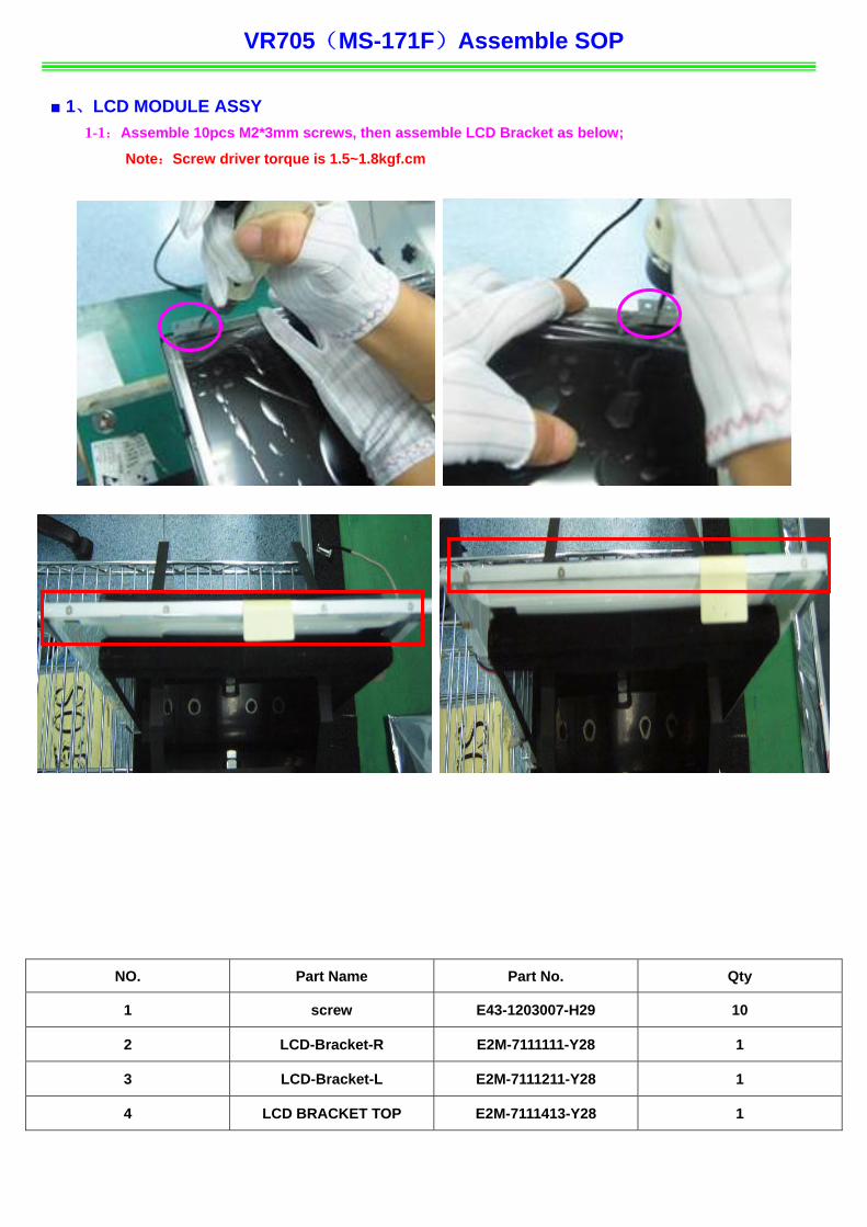
■ 1、LCD MODULE ASSY 1-1:Assemble 10pcs M2*3mm screws, then assemble LCD Bracket as below;
Note:Screw driver torque is 1.5~1.8kgf.cm
NO. Part Name Part No. Qty
1 screw E43- 29 1203007-H 10
2 LCD t-R -Bracke E2M-7111111-Y28 1
3 LCD-Bracket-L E2M-7111211-Y28 1
4 LC P D BRACKET TO E2M-7111413-Y28 1
VR705(MS-171F Assemble SOP
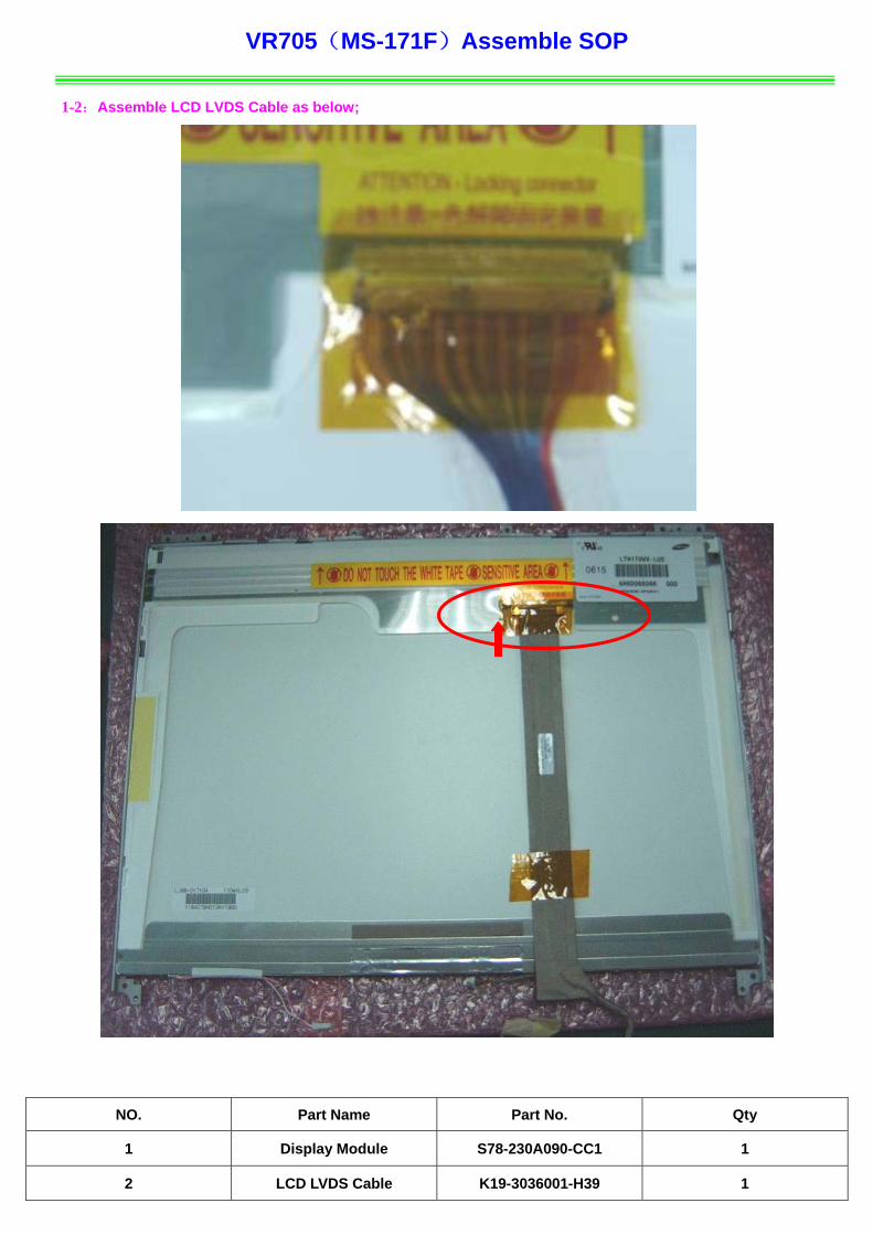
1-2:Assemble LCD LVDS Cable as b
NO. Part Name Part No. Qty
)
elow;
1 Display Module S78-230A090-CC1 1
2 LCD LVDS Cable K19-3036001-H39 1
VR 1F)Assemble SOP
NO. Part Name Part No. Qty
705(MS-17
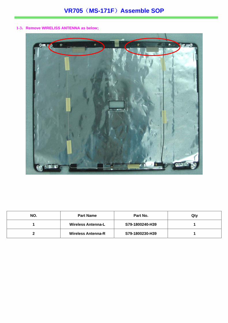
1-3:Remove WIRELISS ANTENNA as below;
1 Wire a-L S79- 39 less Antenn 1800240-H 1
2 Wireless Antenna-R S79-1800230-H39 1
VR705(MS-171F Assemble SOP
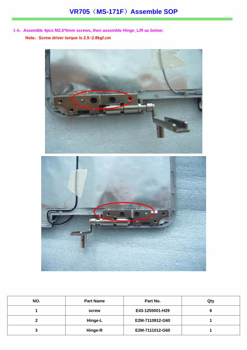
Note:Screw driver torque is 2.5~2.8kgf.cm
NO. Part Name Part No. Qty
)
1-4:Assemble 4pcs M2.5*5mm screws, then assemble Hinge_L/R as below;
1 screw E43-1255001-H29 6
2 Hinge-L E2M-7110912-G60 1
3 Hinge-R E2M-7111012-G60 1
VR70 -171F)Assemble SOP
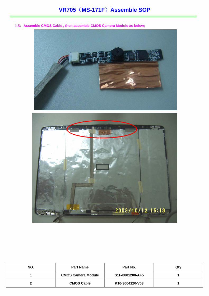
1-5:Assemble CMOS Cab
NO. Part Name Part No. Qty
5(MS
le , then assemble CMOS Camera Module as below;
1 CMOS Camera Module S1F-0001200-AF5 1
2 C K10 03 MOS Cable -3004120-V 1
V F)Assemble SOP
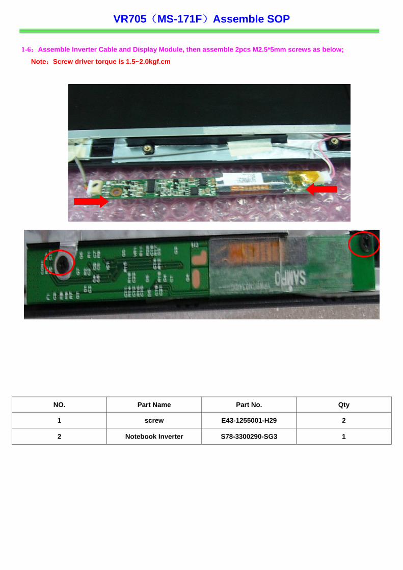
1-6:Assemble Inverter Cab rews as below;
NO. Part Name Part No. Qty
R705(MS-171
le and Display Module, then assemble 2pcs M2.5*5mm sc
Note:Screw driver torque is 1.5~2.0kgf.cm
1 screw E43-1255001-H29 2
2 Not ter S78- G3 ebook Inver 3300290-S 1
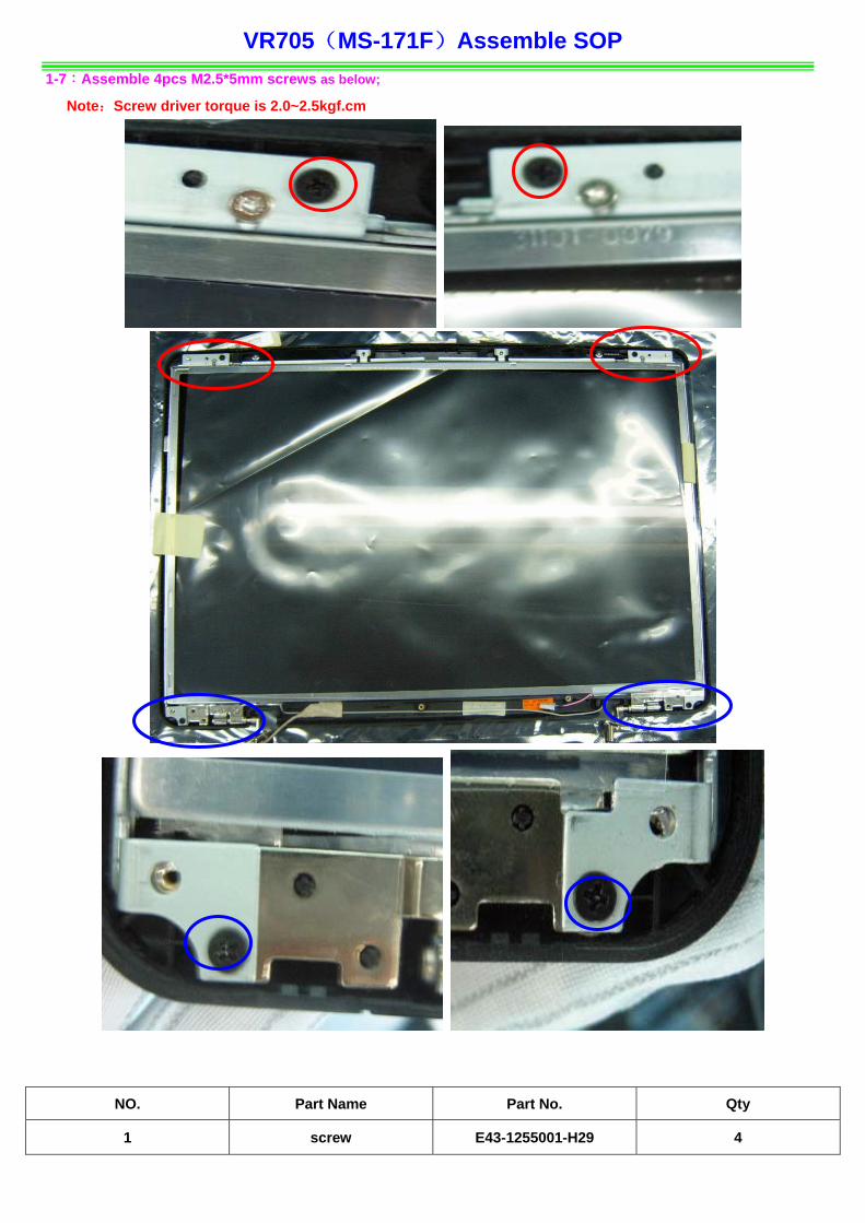
VR705(MS-171F Assemble SOP 1-7:Assemble 4pcs M2.5*5mm screws as below;
Note:Screw driver torque is 2.0~2.5kgf.cm
Part No. Qty
)
NO. Part Name
1 screw E43-1255001-H29 4
VR705(MS-171F Assemble SOP
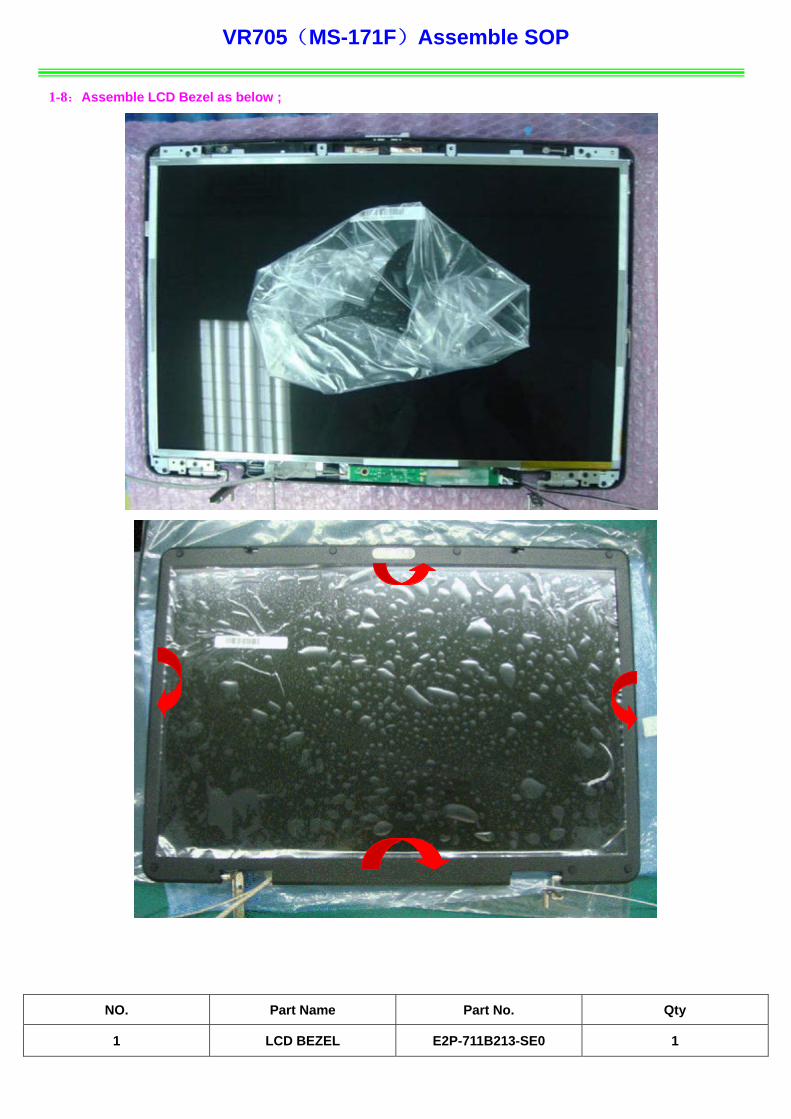
1-8:Assemble LCD Bezel as below ;
)
NO. Part Name Part No. Qty
1 LCD BEZEL E2P-711B213-SE0 1

VR705(MS-171F)Assemble SOP
1-9:Assemble 8pcs M2.5*5mm screws, then assemble 8pcs LCD Rubbers as below;
Note:Screw driver torque is 2.5~2.8kgf.cm
NO. Part Name Part No. Qty
1 LCD RUBBER E25-1035260 4 -Y40
2 LCD RUBBER E25-1035290-Y40 2
3 screw E43-I250551-H29 6
VR70 171F)Assemble SOP
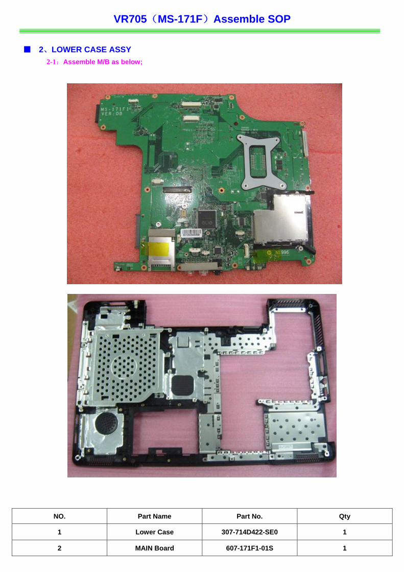
■ 2、L ER CASE ASSY2-1 ble M/B as below;
5(MS-
OW :Assem
Part Name Part No.
NO. Qty
1 Lower Case 307-714D422-SE0 1
2 MAIN Board 607-171F1-01S 1
VR705(MS-171F)Assemble SOP
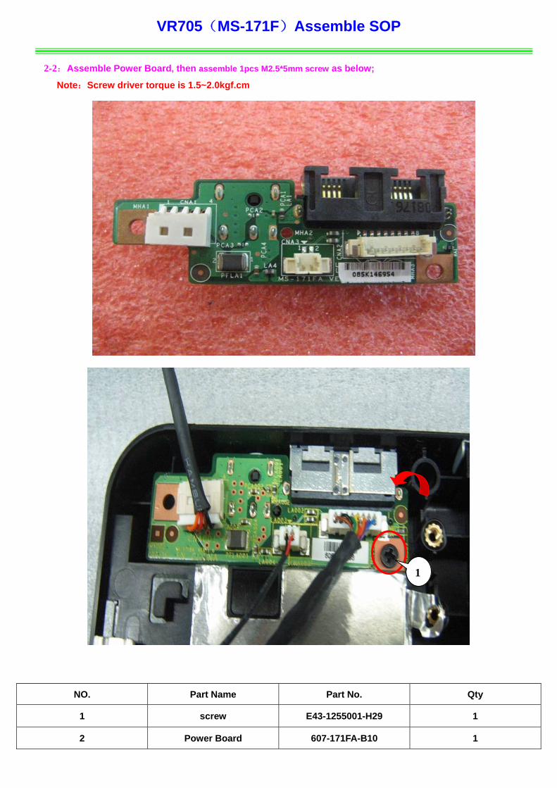
2-2:Assemble Power Board, then assemble 1pcs M2.5*5mm screw as below;
Note driver torque is :Screw 1.5~2.0kgf.cm
NO. y
Part Name Part No. Qt
1
1 screw E43-1255001-H29 1
2 Power Board 607-171FA-B10 1
VR70 171F)Assemble SOP
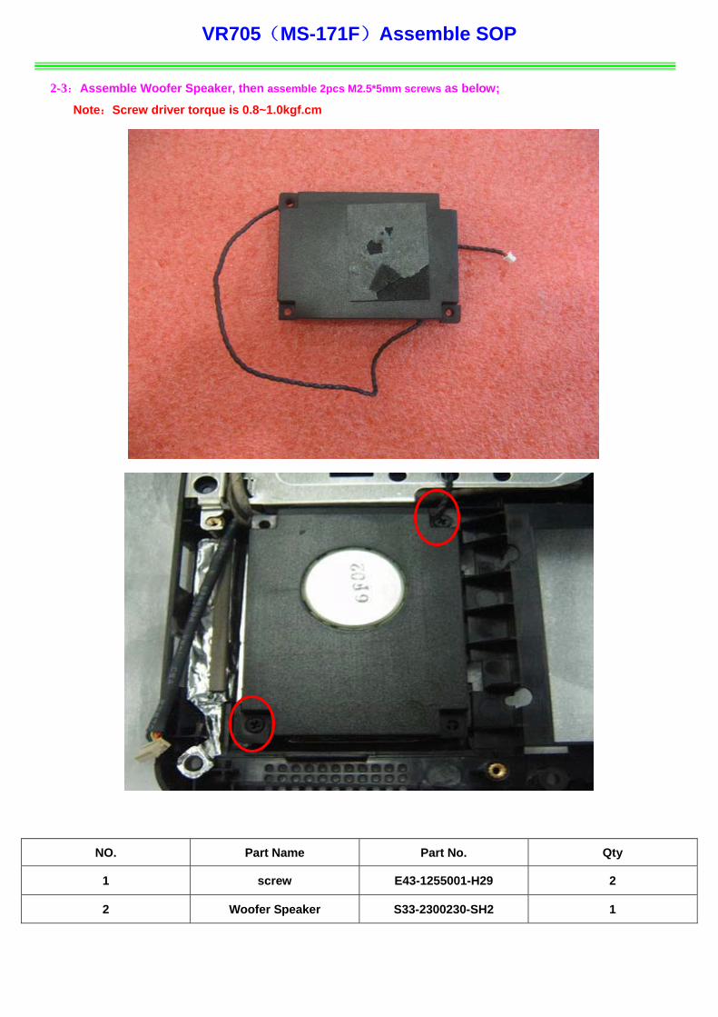
2-3:Assemble Woofer Speaker, 2pcs M2.5*5mm ;
Note:Screw driver torque is 0.8~1.0kgf.cm
5(MS-
then assemble screws as below
NO. Qty
Part Name Part No.
1 screw E43-1255001-H29 2
2 Woofer Speaker S33-2300230-SH2 1

VR705 -171F)Assemble SOP
2-4:Assemble USB Board, then assemble 1pcs M2.5*5mm screw as below;
Note:Screw driver torque is 1.5~2.0kgf.cm
NO. Qty
(MS
Part Name Part No.
1
1 screw E43-1255001-H29 1
2 USB Board 607-171FB-B10 1

VR705(MS-171F Assemble SOP
2-5:Assemble DVBT board, then a M2*3mm sc
Note:Screw driver torque is 1.0~1.5kgf.cm
2-6:
Not
NO. Part Name Part No. Qty
)
ssemble 3pcs rews as below;
Assemble 1pcs M2*3mm screw as below;
e:Screw driver torque is 1.0~1.5kgf.cm
1 screw E43-1203007-H29 4
2 DVBT board S99-0000100-V03 1
3 DVBT Cover 307-7110912-SE0 1
VR705(MS-171F)Assemble SOP
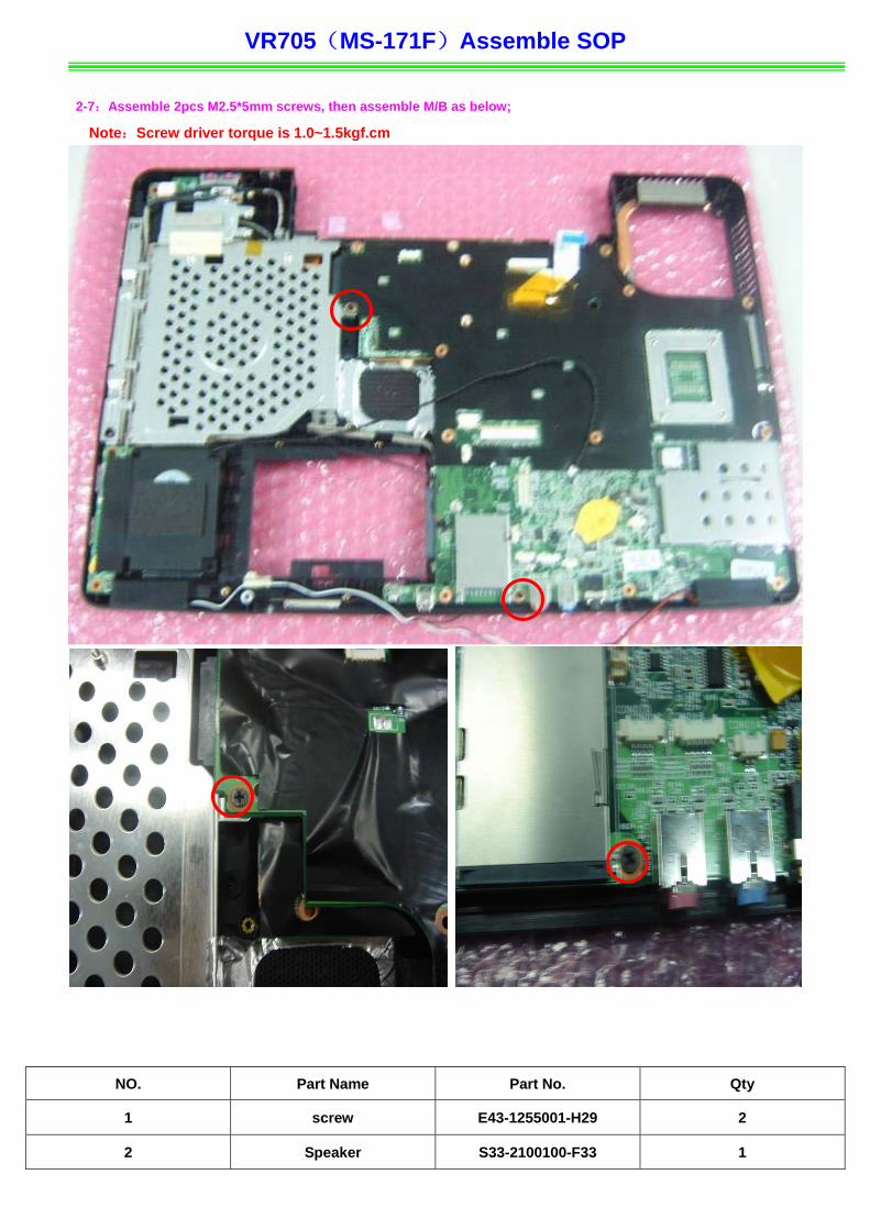
2-7:Assemble 2pcs M2.5*5mm screws, then assemble M/B as below;
Note:Screw driver torque is 1.0~1.5kgf.cm
NO. Part Name Part No. Qty
1 screw 001-H29 2 E43-1255
2 Speaker 100-F33 1 S33-2100
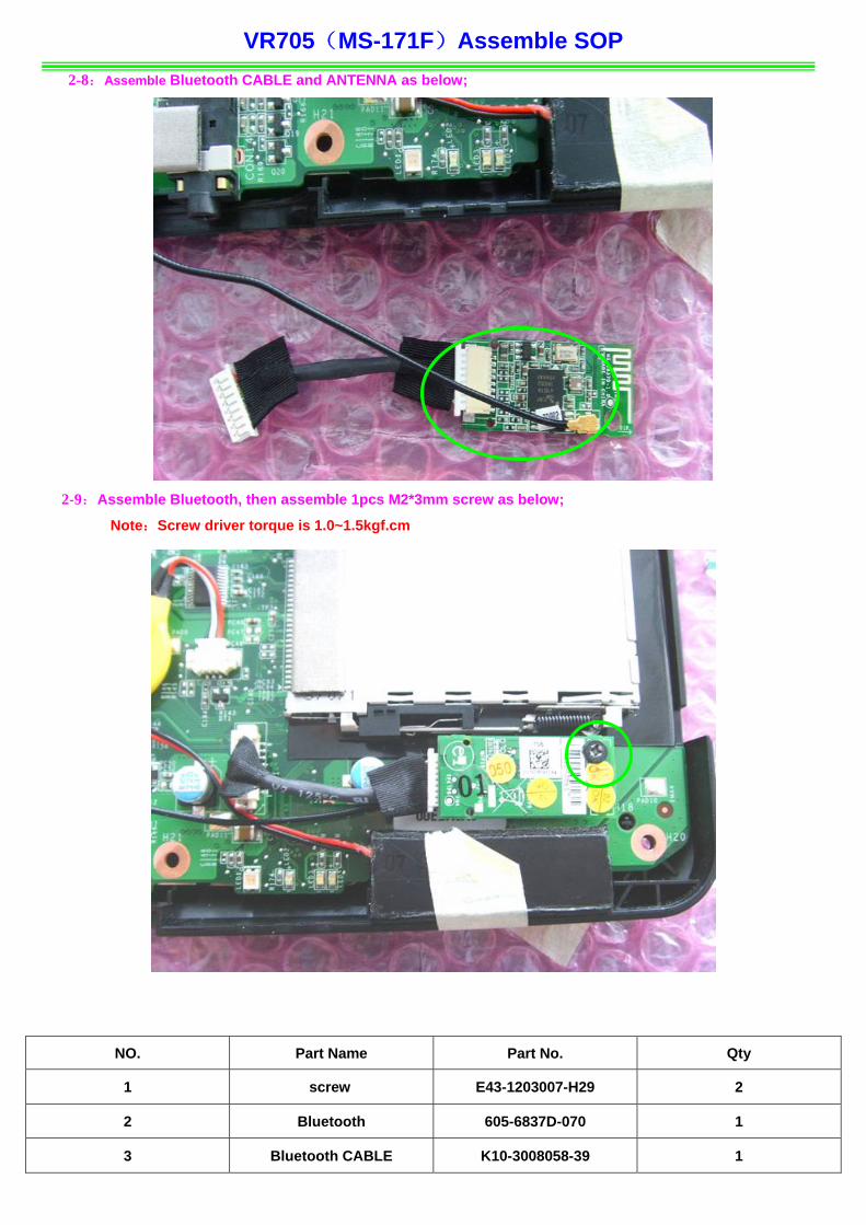
VR705(MS-171F)Assemble SOP 2-8:Assemble Bluetooth CABLE and ANTENNA as below;
2-9:Assemble Bluetooth, then asse 2*3mm scre
Note:Screw driver torque is 1.0~1.5kgf.cm
NO. Qty
mble 1pcs M w as below;
Part Name Part No.
1 screw E43-1203007-H29 2
2 Bluetooth 605-6837D-070 1
3 Bluetooth CABLE K10-3008058-39 1
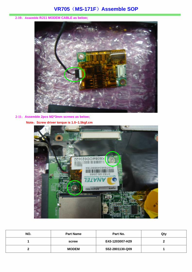
VR705(MS-171F)Assemble SOP 2-10:Assemble RJ11 MODEM CABLE as below;
2-11: 2*3mm s low;
Note:Screw driver torque is 1.0~
NO. Qty
Assemble 2pcs M crews as be
1.5kgf.cm
Part Name Part No.
1 screw E43-1203007-H29 2
2 MODEM S52-2801130-Q09 1
VR705(MS-171F)Assemble SOP
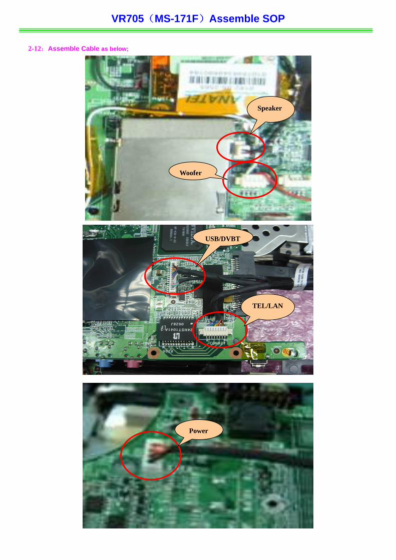
2-12:Assemble Cable as below;
Speaker
Woofer
USB/DVBT
TEL/LAN
Power
VR705(MS-171F)Assemble SOP
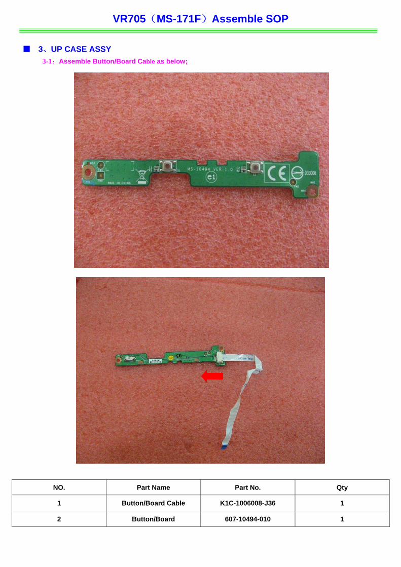
■ 3、UP CASE ASSY 3-1:Assemble Button/Board Cable as below;
NO. Part Name Part No. Qty
1 Button/Board Cable K1C-1006008-J36 1
2 Button/Board 607-10494-010 1

VR705(MS-171F)Assemble SOP
3-2:Assemble Touch Pad Board as below;
NO. Part Name Part No. Qty
1 Touchpad Module S78-3700118-E47 1
2 UPPER CASE 307-714C711-SE0 1
VR705(MS-171F)Assemble SOP
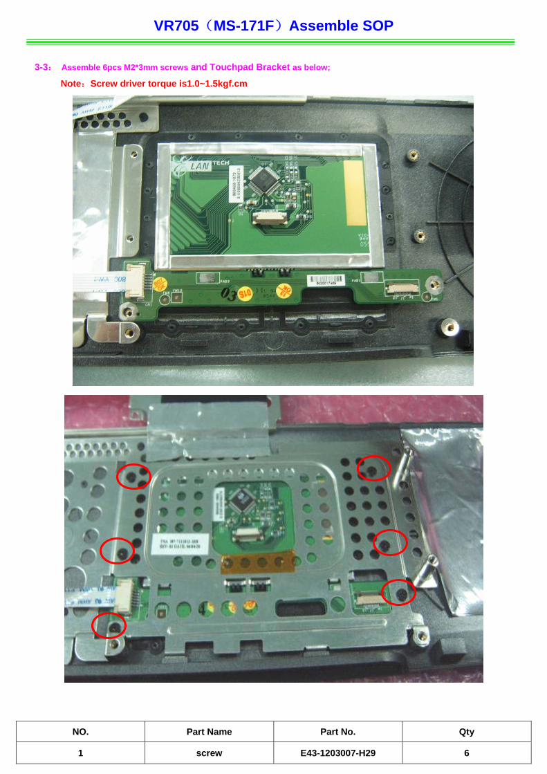
3-3: Assemble 6pcs M2*3mm screws and Touchpad Bracket as below;
Note:Screw driver torque is1.0~1.5kgf.cm
NO. Part Name Part No. Qty
1 screw E43-1203007-H29 6

VR705(MS-171F)Assemble SOP
3-4:Assemble Touch Pad FPC and Microphone as below;
NO. Part Name Part No. Qty
1 Microphone S34-2100120-K03 1
2 Touch Pad FPC K1C-1012010-J36 1
VR705(MS-171F)Assemble SOP
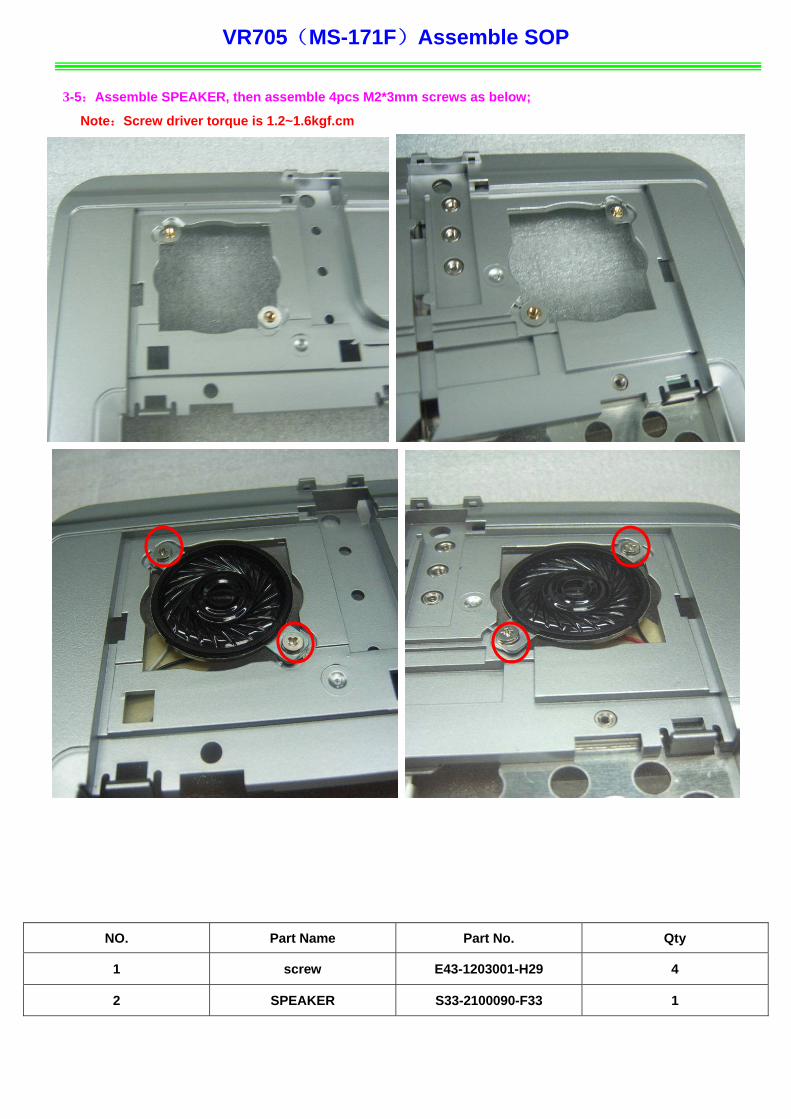
3-5:Assemble SPEAKER, then assemble 4pcs M2*3mm screws as below;
Note:Screw driver torque is 1.2~1.6kgf.cm
NO. Part Name Part No. Qty
1 screw E43-1203001-H29 4
2 SPEAKER S33-2100090-F33 1
VR705(MS-171F)Assemble SOP
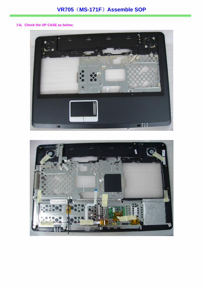
3-6:Check the UP CASE as below;

VR705(MS-171F)Assemble SOP
■ 4、MIDDLE COVER ASSY 4-1:Assemble Touchpad FPC (connected with M/B ) ,SPEAKER and MICROPHONE Cable as below;
Microphone Cable
Speaker Cable
VR705(MS-171F)Assemble SOP
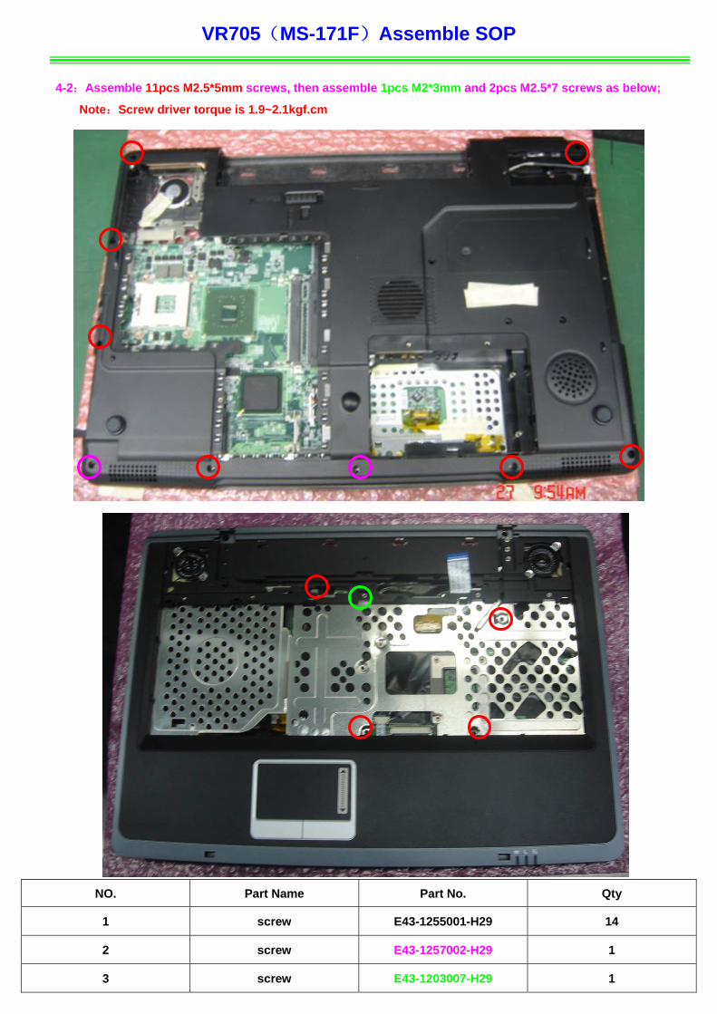
4-2:Assemble 11pcs M2.5*5mm screws, then assemble 1pcs M2*3mm and 2pcs M2.5*7 screws as below;
Note:Screw driver torque is 1.9~2.1kgf.cm
NO. Part Name Part No. Qty
1 screw E43-1255001-H29 14
2 screw E43-1257002-H29 1
3 screw E43-1203007-H29 1
VR705(MS-171F)Assemble SOP
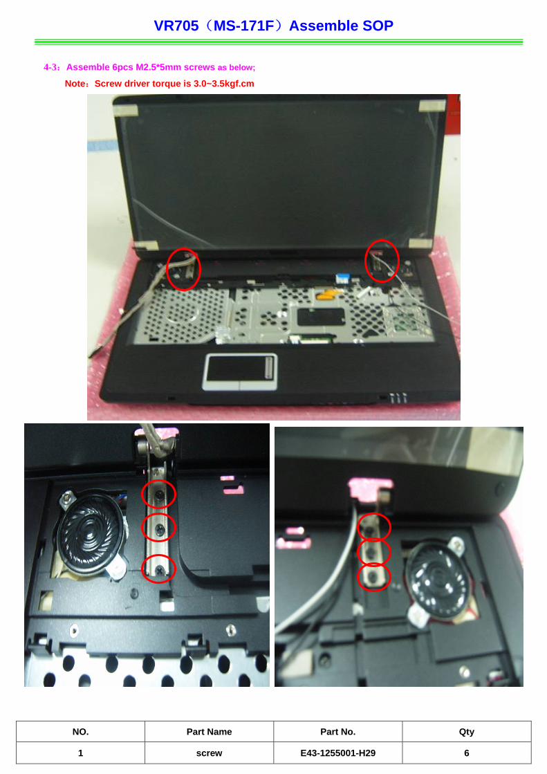
4-3:Assemble 6pcs M2.5*5mm screws as below;
Note:Screw driver torque is 3.0~3.5kgf.cm
NO. Part Name Part No. Qty
1 screw E43-1255001-H29 6

VR705(MS-171F)Assemble SOP
4-4:Check CABLE and ANTENNA as below;
4-5:Assemble LCD LVDS Cable, then assemble CMOS Cable as below;
NO. Part Name Part No. Qty
1 LCD LVDS Cable K19-3036001-H39 1
2 CMOS CABLE K10-3004120-V03 1
VR705(MS-171F)Assemble SOP
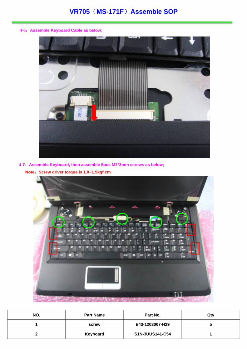
4-6:Assemble Keyboard Cable as below;
4-7:Assemble Keyboard, then assemble 5pcs M2*3mm screws as below;
Note:Screw driver torque is 1.0~1.5kgf.cm
NO. Part Name Part No. Qty
1 screw E43-1203007-H29 5
2 Keyboard S1N-3UUS141-C54 1
VR705(MS-171F)Assemble SOP
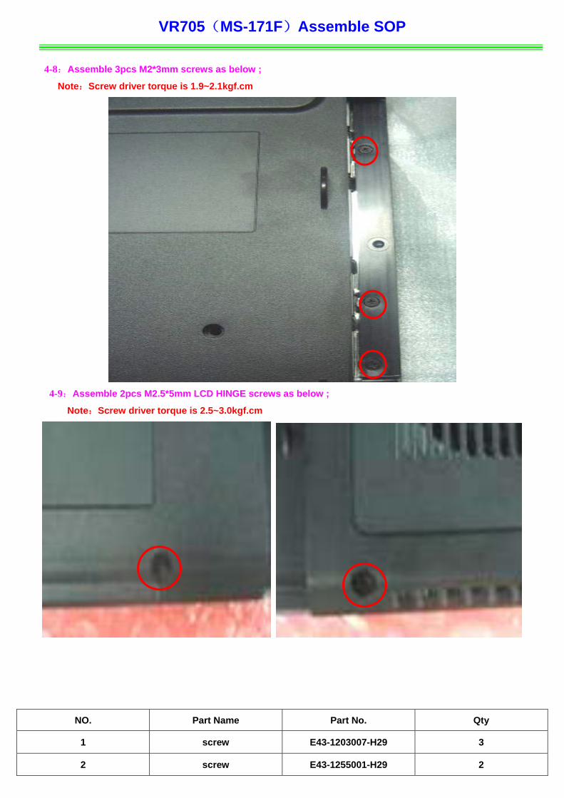
4-8:Assemble 3pcs M2*3mm screws as below ;
Note:Screw driver torque is 1.9~2.1kgf.cm
4-9:Assemble 2pcs M2.5*5mm LCD HINGE screws as below ;
Note:Screw driver torque is 2.5~3.0kgf.cm
NO. Part Name Part No. Qty
1 screw E43-1203007-H29 3
2 screw E43-1255001-H29 2

VR705(MS-171F)Assemble SOP
4-10:Assemble Middle Cover and Program Board, then assemble 3pcs M2*3mm screws as below;
Note:Screw driver torque is 0.8~1.2kgf.cm
sc
NO. Part Name Part No. Qty
1 HINGE COVER 307-714E411-SE0 1
2 Program Board 607-171G2-02S 1
3 Program Board Cable K1C-1014008-J36 1
VR705(MS-171F)Assemble SOP
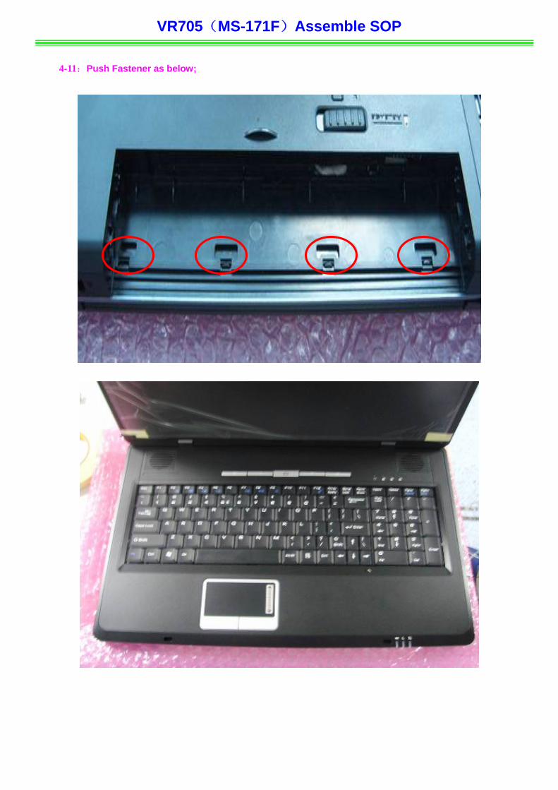
4-11:Push Fastener as below;
VR705(MS-171F)Assemble SOP
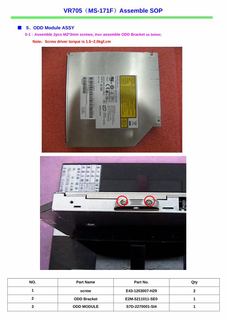
■ 5、ODD Module ASSY 5-1:Assemble 2pcs M2*3mm screws, then assemble ODD Bracket as below;
Note:Screw driver torque is 1.5~2.0kgf.cm
NO. Part Name Part No. Qty
1 screw E43-1203007-H29 2
2 ODD Bracket E2M-5211011-SE0 1
3 ODD MODULE S7D-2270001-SI4 1
VR705(MS-171F)Assemble SOP
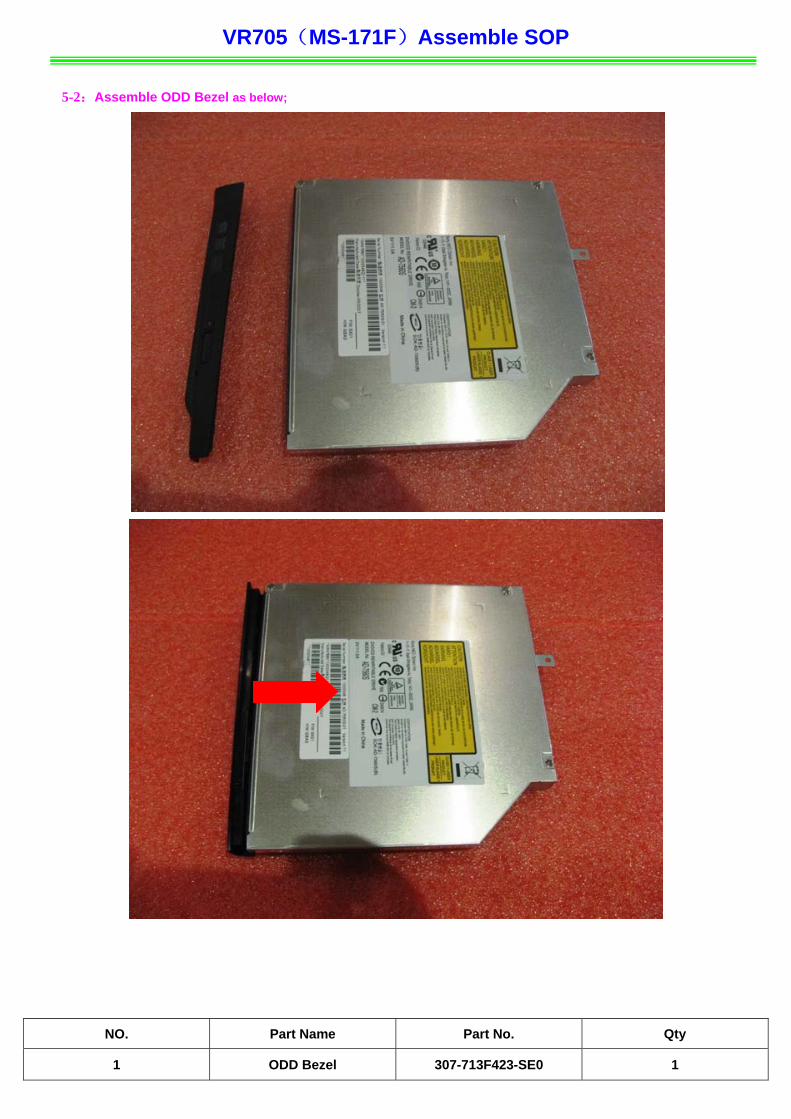
5-2:Assemble ODD Bezel as below;
NO. Part Name Part No. Qty
1 ODD Bezel 307-713F423-SE0 1
VR705(MS-171F)Assemble SOP
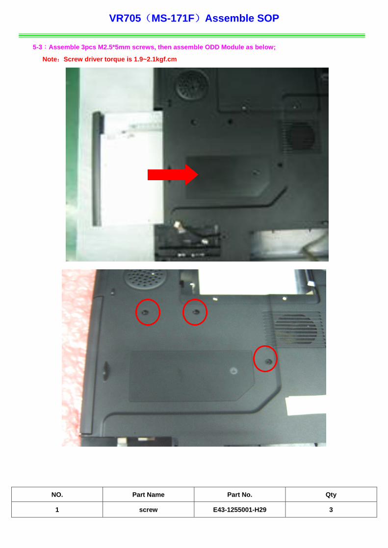
5-3:Assemble 3pcs M2.5*5mm screws, then assemble ODD Module as below;
Note:Screw driver torque is 1.9~2.1kgf.cm
NO. Part Name Part No. Qty
1 screw E43-1255001-H29 3
VR705(MS-171F)Assemble SOP
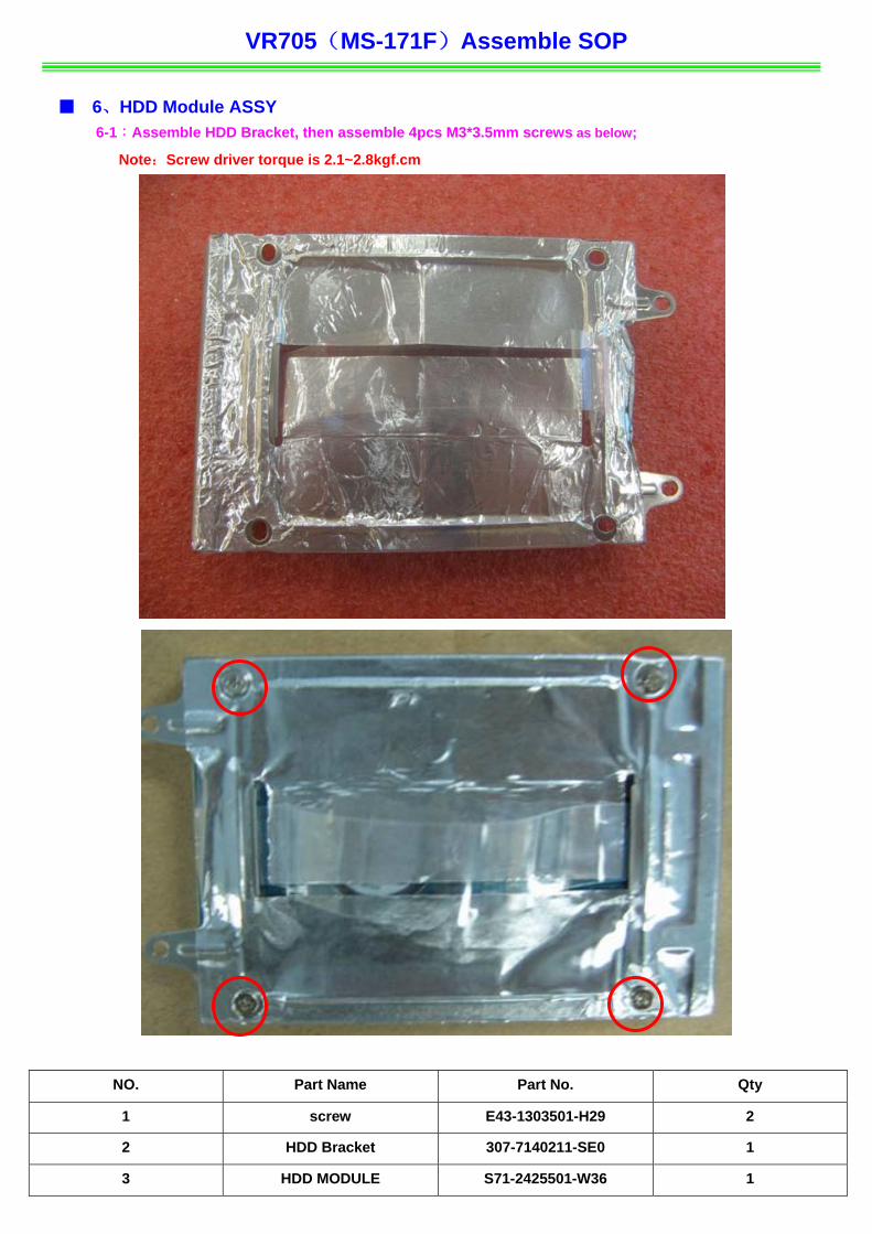
■ 6、HDD Module ASSY 6-1:Assemble HDD Bracket, then assemble 4pcs M3*3.5mm screws as below;
Note:Screw driver torque is 2.1~2.8kgf.cm
NO. Part Name Part No. Qty
1 screw E43-1303501-H29 2
2 HDD Bracket 307-7140211-SE0 1
3 HDD MODULE S71-2425501-W36 1
VR705(MS-171F)Assemble SOP
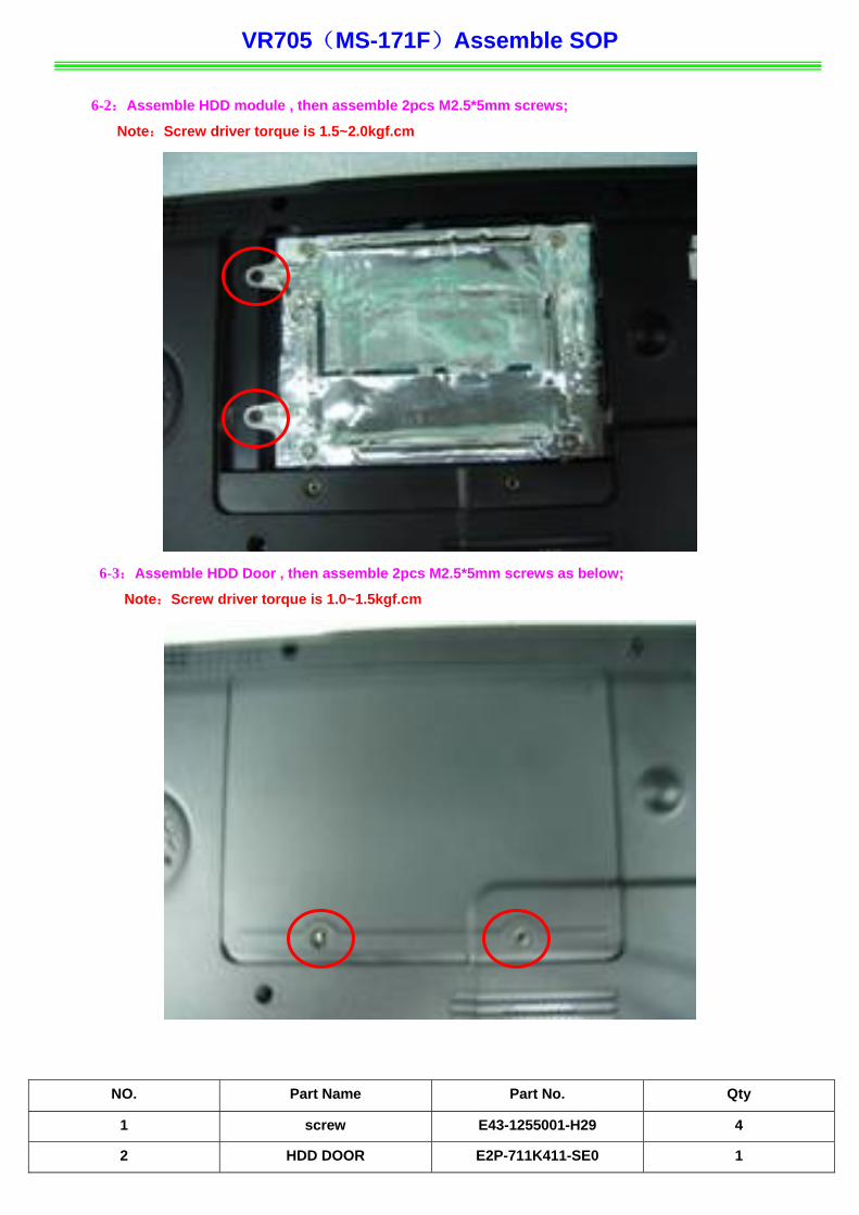
6-2:Assemble HDD module , then assemble 2pcs M2.5*5mm screws;
Note:Screw driver torque is 1.5~2.0kgf.cm
6-3:Assemble HDD Door , then assemble 2pcs M2.5*5mm screws as below;
Note:Screw driver torque is 1.0~1.5kgf.cm
NO. Part Name Part No. Qty
1 screw E43-1255001-H29 4
2 HDD DOOR E2P-711K411-SE0 1

VR705(MS-171F)Assemble SOP
■ 7、RAM、WLAN Module 7-1:Assemble WIRELESS CARD as below;
7-2:Assemble 1pcs M2*3mm screw, and then assemble ANTENNA/R-L as below;
Note:Screw driver torque is 1.0~1.5kgf.cm
1
NO. Part Name Part No. Qty
1 screw E43-1203007-H29 1
2 WIRELESS CARD S57-3800010-T46 1
VR705(MS-171F)Assemble SOP
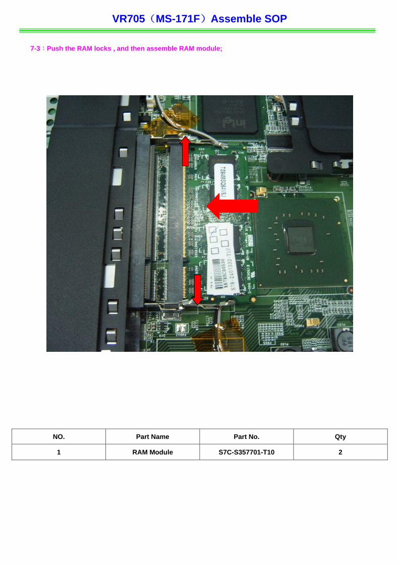
7-3:Push the RAM locks , and then assemble RAM module;
NO. Part Name Part No. Qty
1 RAM Module S7C-S357701-T10 2
VR705(MS-171F)Assemble SOP ■ 8、THERMAL-KIT And CPU Module
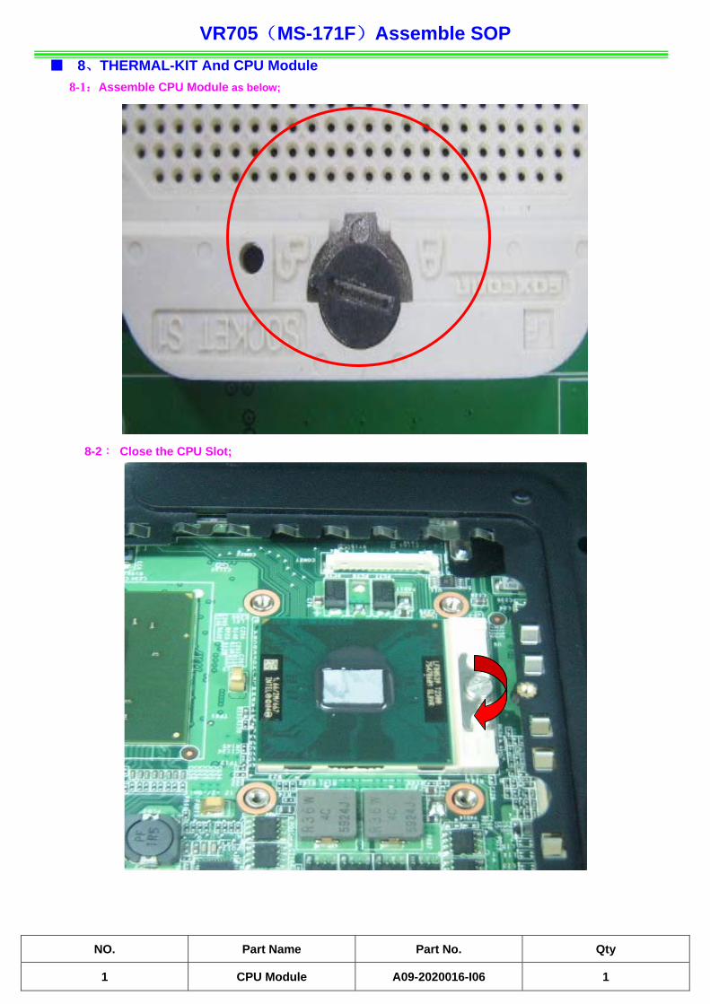
8-1:Assemble CPU Module as below;
8-2: Close the CPU Slot;
NO. Part Name Part No. Qty
1 C A09 I06 PU Module -2020016- 1
VR7 171F)Assemble SOP
NO. Part Name Part No. Qty
05(MS-
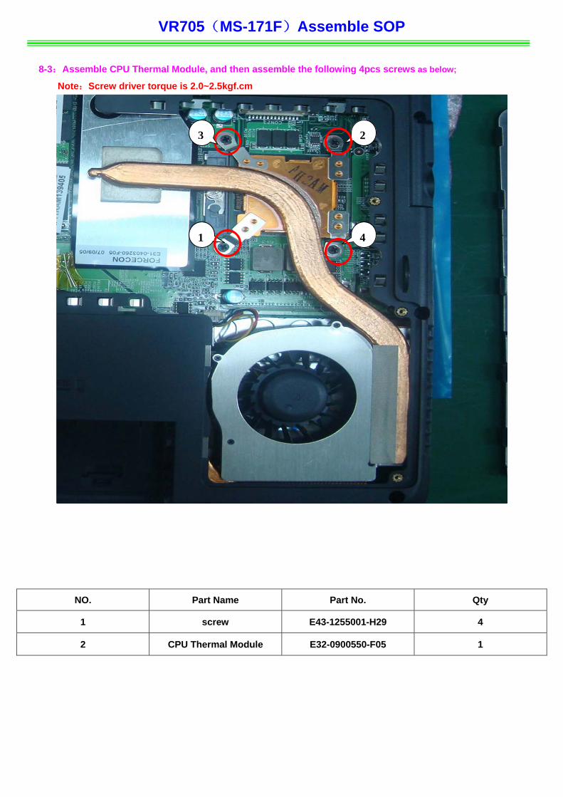
8-3:Assemble CPU Thermal Module, and then assemble the following 4pcs screws as below;
Note:Screw driver torque is 2.0~2.5kgf.cm
1 screw E43-1255001-H29 4
2 CPU dule E32 05 Thermal Mo -0900550-F 1
1
3 2
4
VR705(MS-171F Assemble SOP
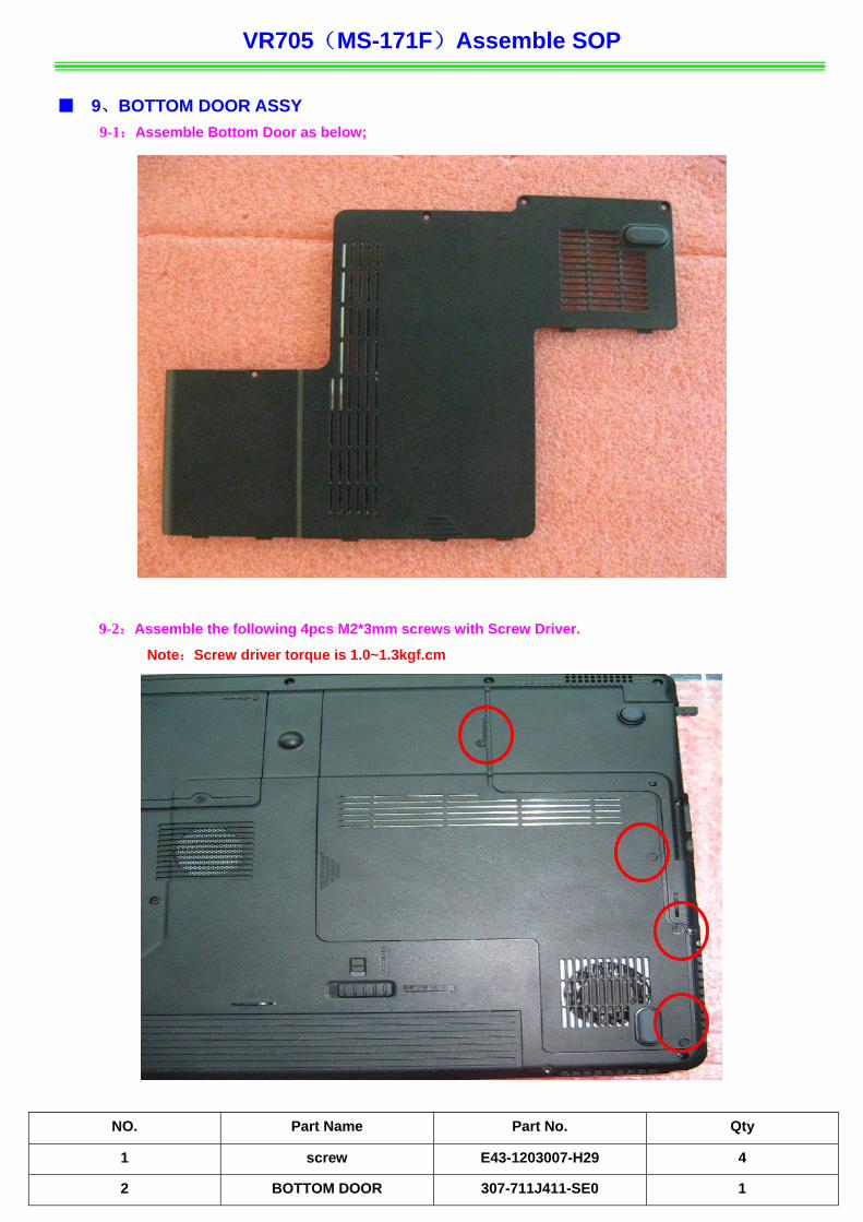
■ 9、BOTTOM DOOR ASSY
9-1:Assemble Botto
)
m Door as below;
9-2:Assemble the following 4pcs M2*3mm screws with Screw Driver.
Note:Screw driver torque is 1.0~1.3kgf.cm
NO. Qty
Part Name Part No.
1 screw E43-1203007-H29 4
2 1 BOTTOM DOOR 307-711J411-SE0
VR705(MS-171F Assemble SOP
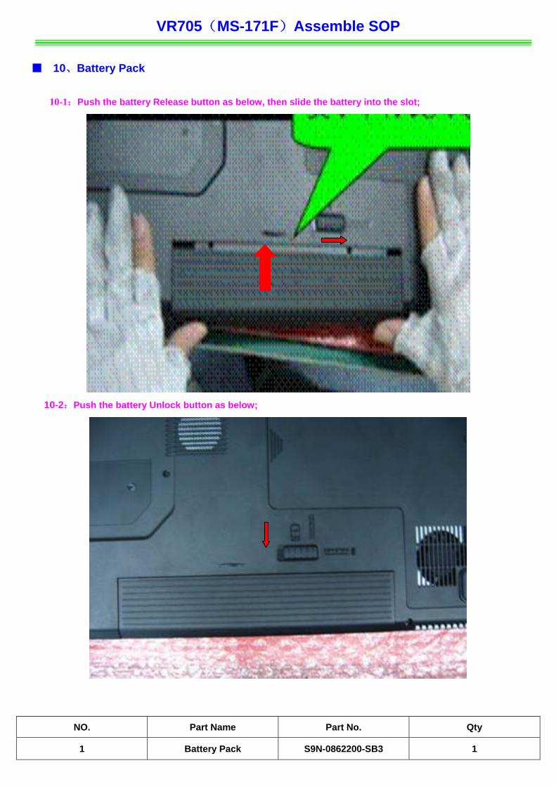
■ 10、 Pack
10-1:Push the battery R ot;
10-2:
NO. Qty
)
Battery
elease button as below, then slide the battery into the sl
Push the battery Unlock button as below;
Part Name Part No.
1 Battery Pack S9N-0862200-SB3 1
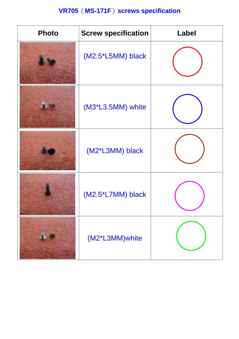
VR705(MS-171F)screws specification
Photo Screw specification Label
(M2.5*L5MM) black
(M3*L3.5MM) white
(M2*L3MM) black
(M2.5*L7MM) black
(M2*L3MM)white
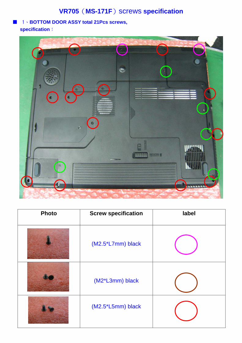
VR705(MS-171F)screws specification ■ 1、BOTTOM DOOR ASSY total 21Pcs screws,
specification:
Photo Screw specification label
(M2.5*L7mm) black
(M2*L3mm) black
(M2.5*L5mm) black
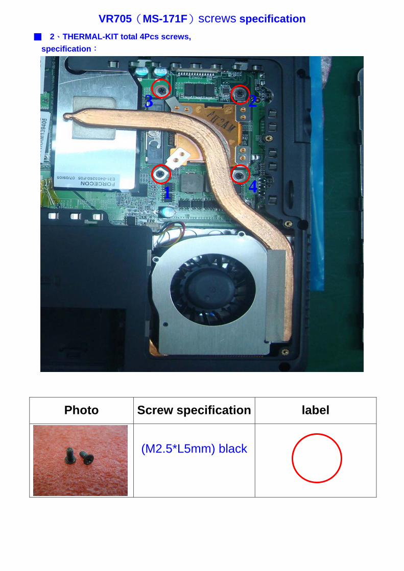
VR705(MS-171F)screws specification ■ 2、THERMAL-KIT total 4Pcs screws,
specification:
3
1
2
4
Photo Screw specification label
(M2.5*L5mm) black
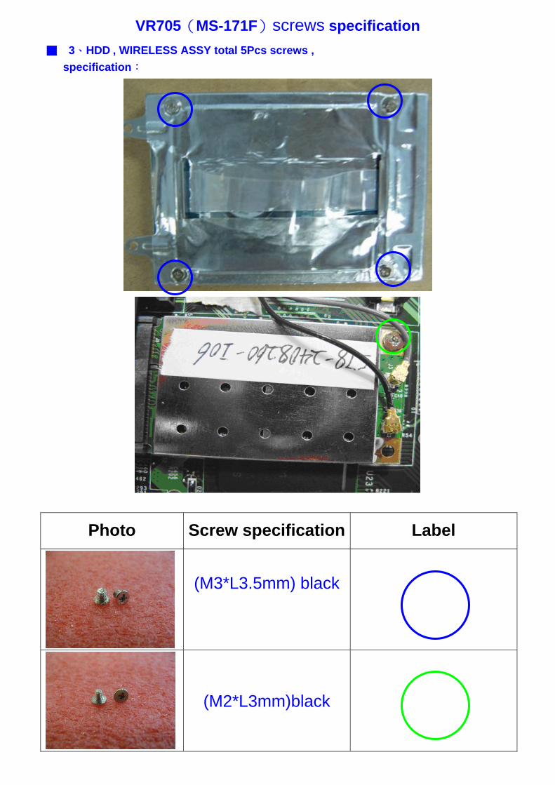
VR705(MS-171F)screws specification ■ 3、HDD , WIRELESS ASSY total 5Pcs screws ,
specification:
Photo Screw specification Label
(M3*L3.5mm) black
(M2*L3mm)black
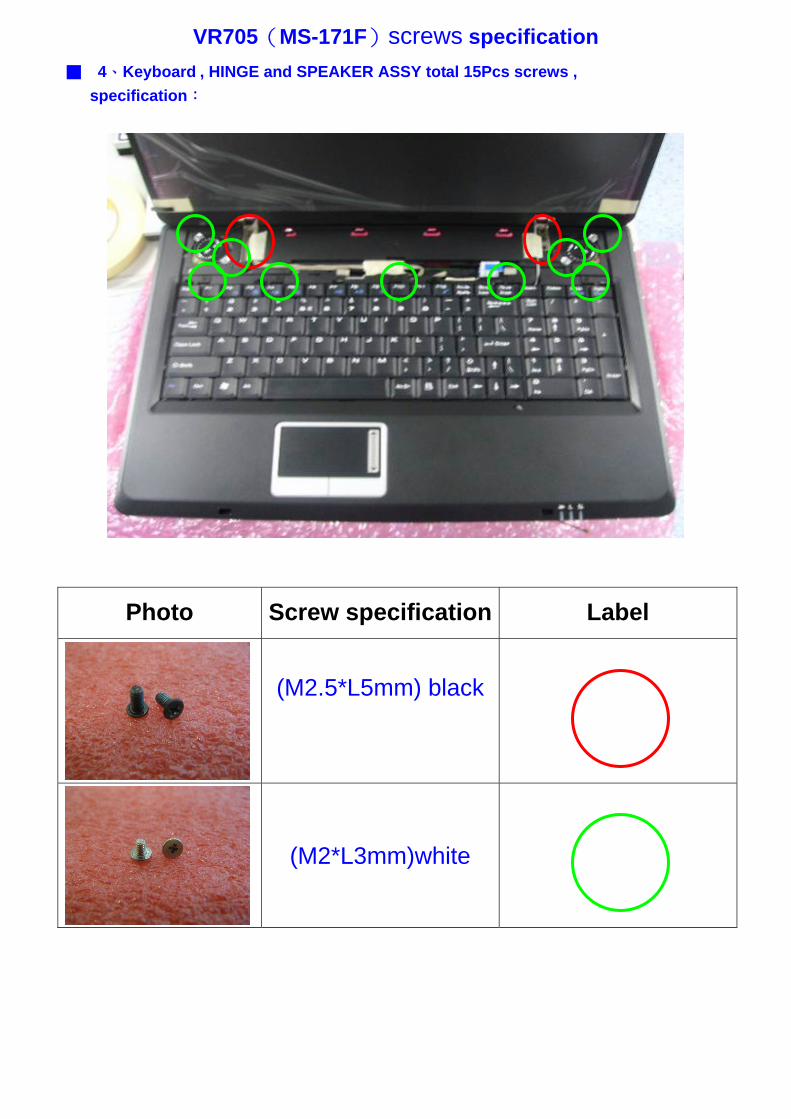
VR705(MS-171F)screws specification ■ 4、Keyboard , HINGE and SPEAKER ASSY total 15Pcs screws ,
specification:
Photo Screw specification Label
(M2.5*L5mm) black
(M2*L3mm)white
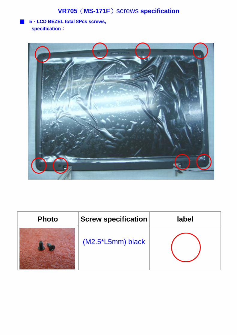
VR705(MS-171F)screws specification ■ 5、LCD BEZEL total 8Pcs screws,
specification:
Photo Screw specification label
(M2.5*L5mm) black
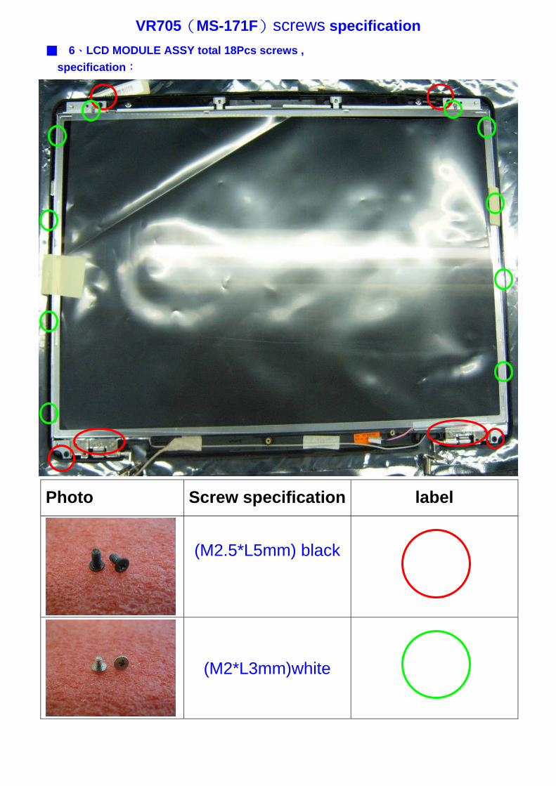
VR705(MS-171F)screws specification ■ 6、LCD MODULE ASSY total 18Pcs screws ,
specification:
Photo Screw specification label
(M2.5*L5mm) black
(M2*L3mm)white
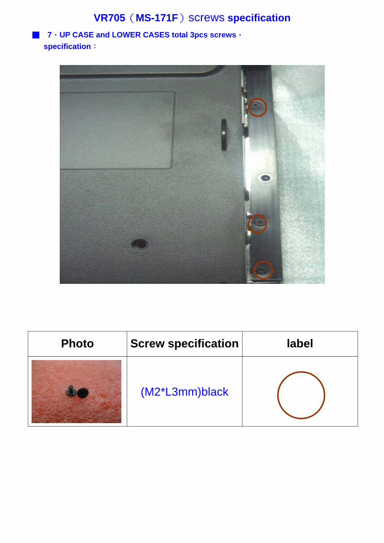
VR705(MS-171F)screws specification ■ 7、UP CASE and LOWER CASES total 3pcs screws,
specification:
Photo Screw specification label
(M2*L3mm)black
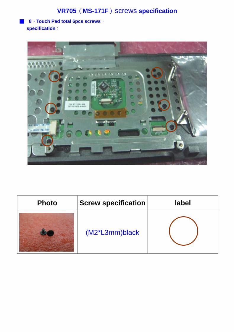
VR705(MS-171F)screws specification ■ 8、Touch Pad total 6pcs screws,
specification:
Photo Screw specification label
(M2*L3mm)black

VR705(MS-171F)screws specification ■ 9、NB total 2pcs screws
specification:
Photo Screw specification label
(M2.5*L5mm) black