waimakariri (ped, ash & leg) installation & operation manual · waimakariri (ped, ash &...
TRANSCRIPT

1
WAIMAKARIRI (PED, ASH & LEG) Ultra-low Emission Burner Installation & Operation Manual
THIS MANUAL CONTAINS IMPORTANT INFORMATION. PLEASE KEEP IT IN A SAFE PLACE FOR FUTURE REFERENCE.
Manufactured in New Zealand by: GLEN DIMPLEX NEW ZEALAND LIMITED P.O. Box 58473, Botany, Manukau - 2163 Ph: 0800 666 2824 Fax: 09 274 8472 Email: [email protected] Web: www.glendimplex.co.nz 4th Mar 2020 Part No. 599386 V1.1 *Glen Dimplex New Zealand Ltd reserves the right to change specifications, the content of this manual, or the design of its product without prior notice.

2
CONTENTS
PAGE
1.0 INTRODUCTION 3
1.1 ITEMS SUPPLIED WITH THE FIRE 3
1.2 HANDLING AND TRANSPORT 3
1.3 WARNINGS 4
1.4 CAUTIONS 4
2.0 TECHNICAL SPECIFICATIONS 5
3.0 INSTALLATION OF THE WAIMAKARIRI ULEB 6
3.1 UNPACKING 6
3.2 POSITIONING 6
3.3 FLUE REQUIREMENTS 6
3.4 FLOOR PROTECTOR REQUIREMENTS 7
3.5 REDUCING CLEARANCES 7
3.6 SEISMIC RESTRAINT 8
3.7 PREPARING THE BURNER FOR FIRST LIGHT-UP 9
4.0 PERMITTED FUELS 13
4.1 TESTING YOUR WOOD MOISTURE 13
4.2 RECOMMENDED FUEL LOG SIZES 13
5.0 OPERATIONAL SEQUENCE 14
5.1 BEFORE FIRST LIGHT-UP 14
5.2 COLD START-UP 14
5.2.1 KINDLING + INTERMEDIATE LOAD 1 14
5.2.2 INTERMEDIATE LOAD 2 14
5.2.3 MAIN LOAD 15
5.2.4 RE-FUELING & SHUT-DOWN 15
6.0 CATALYTIC COMBUSTOR & MAINTENANCE 16
6.1 HOW IT WORKS 16
6.2 BEST PRACTICES TO ENHANCE LIFE OF COMBUSTOR 16
6.3 INSPECTING CATALYTIC COMBUSTOR 17
6.4 REMOVAL OF CATALYTIC COMBUSTOR 17
6.5 CLEANING OF CATALYTIC COMBUSTOR 17
6.6 WHEN TO REPLACE CATALYTIC COMBUSTOR 18
6.7 DIFFERENT STATES OF CATALYTIC COMBUSTOR 19
6.8 MAINTENANCE OF OTHER WAIMAKARIRI PARTS 20
7.0 WAIMAKARIRI REPLACEMENT PARTS 21
8.0 TROUBLESHOOTING: CAUSES & REMEDY 22
WAIMAKARIRI WARRANTY REGISTRATION 25
WAIMAKARIRI WARRANTY TERMS & CONDITIONS 27

3
1.0 Introduction
Congratulations! You are the owner of a state-of-the-art Ultra Low Emission Burner “Masport Waimakariri” designed and developed by Glen Dimplex New Zealand. Thank you for purchasing a Masport appliance. The WAIMAKARIRI ULEB is a new generation catalytic wood fire, designed to provide you with all the warmth and comfort of a fireplace, at the same time having ULTRA LOW emissions to dramatically reduce the impact on the environment. Environment Canterbury has approved the installation of this burner in all clean air zones that have been previously banned for the installation of a conventional wood burner. As it bears the Masport brand, it promises to provide you with the economy, safety, and efficiency. To make the most of your appliance, it is important to install, operate, and maintain the burner correctly. Please read this installation and operations manual carefully before installing or operating your WAIMAKARIRI ULEB. Please take the time to understand the basic principles of this new burner which uses a catalytic combustion technology. Your Waimakariri ULEB burns less fuel and produces more consistent heat than a conventional wood burner while producing fewer particulates. The catalytic combustor fitted in this burner is made out of special high-grade stainless steel, which is coated with a catalytic coating. When heated to over 3000C, it will begin to light off (glow), and the combustor begins to burn off small fine unburnt particulates from the combustion gases. The catalyst will then rise in temperature up to approximately 5000C and reaches its optimum stage. During the initial light-up phase with the damper in the open position, the combustion gases are allowed to pass over and through the catalyst, preheating the catalyst. After approx. 20 minutes, the catalyst will reach the required temperature. At this stage, the damper is closed, and all combustion gases are passed through the catalyst, which will start burning the finer unburnt particles. Overall, the catalytic combustion technology is a more effective and efficient way of burning wood, which gives significantly fewer emissions and returns maximum heat from reduced fuel consumption.
1.1 Items supplied with the fire
- Waimakariri ULEB - 1 x Baffle - 1 x Catalytic Combustor Assembly - 1 x Stainless Steel Flame Arrestor Plate - 2 x Full + 4 x Cut Masonry Bricks - 345mm x 345mm Ceiling plate - Accessory Pack – which contains
- 1 x Installation and Operations Manual - Tool for removing flame arrestor plate - 1 x Door Handle
1.2 Handling and Transport The WAIMAKARIRI ULEB has a total weight of 135 kg. Single person handling could cause injury; hence Glen Dimplex recommends suitable handling equipment and two persons while handling, both outside and inside the house. Removing bricks and loose items inside the firebox will help to reduce weight and will ease the handling of the burner during installation. All precautions have been taken during the design of packaging to avoid transport damage until the burner reaches the customer’s house. In case any damage is found while opening the fire, please report it to your dealer immediately before installing the burner.

4
1.3 Warnings
The installation of the Waimakariri ULEB requires a building consent before installation commences. Check with your local Building Authority whether there are any extra requirements before commencing installation.
The Waimakariri ULEB and flue system shall be installed in accordance with AS/NZS 2918:2001 and appropriate requirements of the relevant local building codes.
Glen Dimplex highly recommends NZHHA trained SFAIT (Solid Fuel Appliance Installation technician) installer for installation of the Waimakariri ULEB. Your dealer or heating specialist will be able to help with recommendations as well as advice on permits/consents required for the installation in your area.
Please read carefully all the dimensions and recommendations provided on the technical specification section of this manual. The dimensions given comply with the required safety standard AS/NZS 2918:2001.
Safety and emissions performance of WAIMAKARIRI can be affected by altering the appliance; hence no modifications are allowed without written permission from the manufacturer.
Please ensure that only components approved by Glen Dimplex New Zealand are used for the installation, as substitutes may adversely affect performance and might nullify compliance with the requirements of AS/NZS 2918 safety standard.
The Waimakariri ULEB should be installed with a Masport flue system. Modifying the dimensional specification of components may result in hazardous conditions. Where
such action is considered, the manufacturer should be consulted in the first instance. The Waimakariri ULEB must be serviced at least once every 2 years from service agent trained
and authorized by Glen Dimplex New Zealand. The catalytic combustor used in the Waimakariri ULEB must be inspected and maintained
periodically. Read section 6.0 on the monitoring and maintenance of the catalyst carefully and follow the instructions.
1.4 Caution
This appliance is not intended for use by persons (including children) with reduced physical, sensory, or mental capabilities, or lack of experience and knowledge unless they have been given supervision or instruction concerning use of the appliance by a person responsible for their safety.
Do not leave children unattended near the alighted fire and keep them well away from the fire when in use. Supervise young children to ensure that they do not play with the appliance.
Do not use flammable liquids or aerosols to start or rekindle the fire. Also, do not use such flammable materials near this appliance when it is operating.
Always keep clothing, firewood, furnishing, and other combustible materials at a safe distance from the fire.
Do not touch any part of the fire other than the door and the damper handle when in use as all other parts can be extremely hot.
Cracked/broken door glass, makes the installation unsafe. Do not operate the fire with cracked glass.
Do not attempt to clean or maintain the fire when in use or with hot embers in the combustion chamber. Ensure that embers and all other parts of the fire have cooled down completely before starting ash removal or other maintenance.
Do not use the fire if there is a malfunction, a suspicion of breakage or unusual noises. Contact your nearest Masport dealer or customer service team at Glen Dimplex New Zealand.
This appliance should always be operated & maintained as per instructions in this manual.
Failure to follow above warnings, cautionary measures and instruction given in this installation and operation manual will void the Masport warranty of this product.
5
Waimakariri ULEB (PED, ASH & LEG) – Technical Specifications
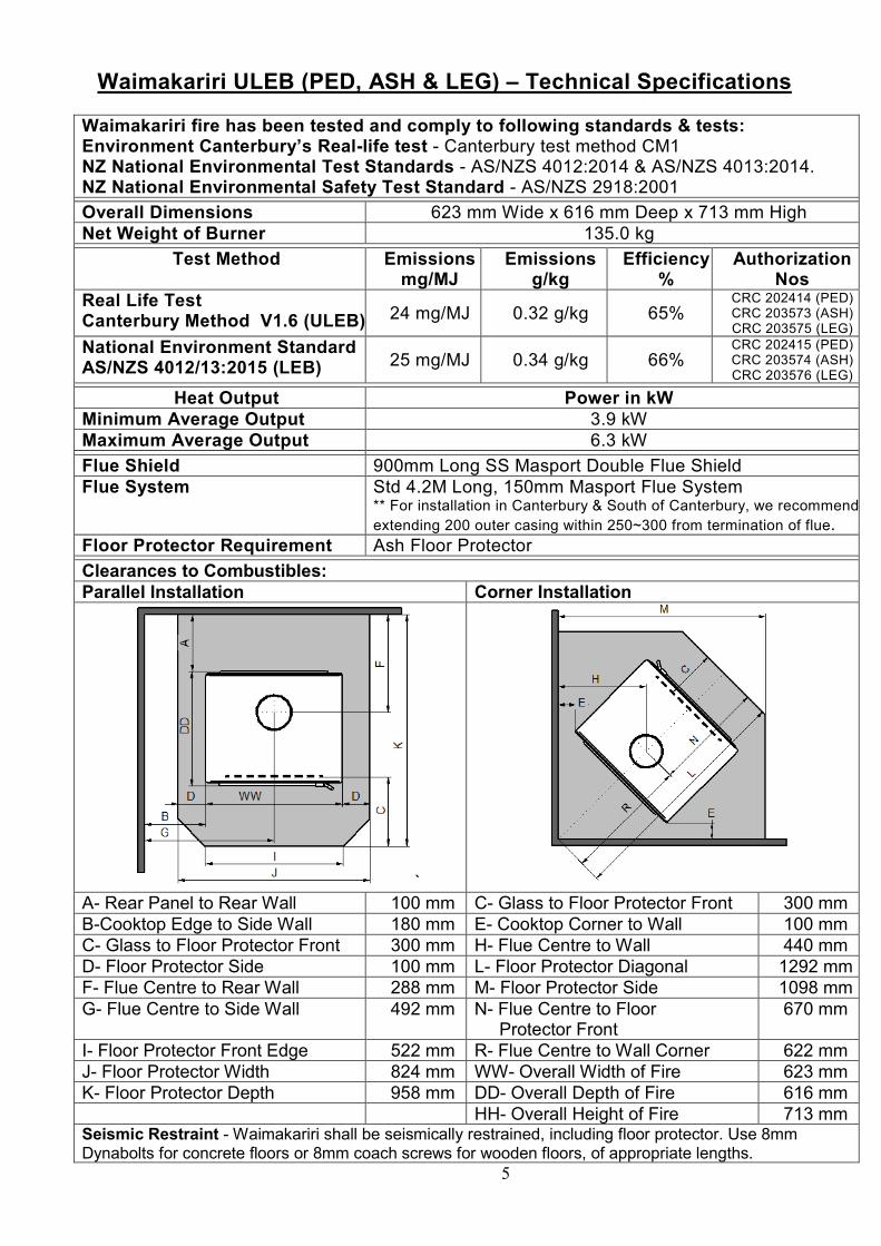
Waimakariri fire has been tested and comply to following standards & tests: Environment Canterbury’s Real-life test - Canterbury test method CM1 NZ National Environmental Test Standards - AS/NZS 4012:2014 & AS/NZS 4013:2014. NZ National Environmental Safety Test Standard - AS/NZS 2918:2001
Overall Dimensions 623 mm Wide x 616 mm Deep x 713 mm High Net Weight of Burner 135.0 kg
Test Method Emissions mg/MJ
Emissions g/kg
Efficiency %
Authorization Nos
Real Life Test Canterbury Method V1.6 (ULEB) 24 mg/MJ 0.32 g/kg 65%
CRC 202414 (PED) CRC 203573 (ASH) CRC 203575 (LEG)
National Environment Standard AS/NZS 4012/13:2015 (LEB) 25 mg/MJ 0.34 g/kg 66%
CRC 202415 (PED) CRC 203574 (ASH) CRC 203576 (LEG)
Heat Output Power in kW Minimum Average Output 3.9 kW Maximum Average Output 6.3 kW
Flue Shield 900mm Long SS Masport Double Flue Shield Flue System Std 4.2M Long, 150mm Masport Flue System
** For installation in Canterbury & South of Canterbury, we recommend
extending 200 outer casing within 250~300 from termination of flue. Floor Protector Requirement Ash Floor Protector
Clearances to Combustibles: Parallel Installation Corner Installation
`
A- Rear Panel to Rear Wall 100 mm C- Glass to Floor Protector Front 300 mm B-Cooktop Edge to Side Wall 180 mm E- Cooktop Corner to Wall 100 mm C- Glass to Floor Protector Front 300 mm H- Flue Centre to Wall 440 mm D- Floor Protector Side 100 mm L- Floor Protector Diagonal 1292 mm F- Flue Centre to Rear Wall 288 mm M- Floor Protector Side 1098 mm G- Flue Centre to Side Wall 492 mm N- Flue Centre to Floor
Protector Front 670 mm
I- Floor Protector Front Edge 522 mm R- Flue Centre to Wall Corner 622 mm J- Floor Protector Width 824 mm WW- Overall Width of Fire 623 mm K- Floor Protector Depth 958 mm DD- Overall Depth of Fire 616 mm HH- Overall Height of Fire 713 mm Seismic Restraint - Waimakariri shall be seismically restrained, including floor protector. Use 8mm Dynabolts for concrete floors or 8mm coach screws for wooden floors, of appropriate lengths.
6
3.0 Installation of the Waimakariri ULEB 3.1 Unpacking Remove the shipping wooden crate and packing around the burner. Remove the loose pieces from the firebox. Remove and discard the screws holding the wood fire to the shipping pallet. Using appropriate lifting equipment, move the burner close to its installation position. Correct lifting procedures should be observed to avoid injury while handling a Masport Waimakariri ULEB.
3.2 Positioning The Waimakariri ULEB has been tested and complies with a parallel or corner wall configuration, with minimum distances to heat-sensitive materials in accordance with the AS/NZ 2918:2001 safety test standard. Determine the installation position for your Waimakariri ULEB only after considering the necessary clearances (See Technical Specifications on page 5 of this manual) and checking the practicability of installing the flue system. No wall or other fixed objects should be closer to the front of the Waimakariri ULEB than two meters. Regard heat resistant walls with heat-sensitive surface treatments (e.g., wallpaper or heat-sensitive paints) as heat-sensitive walls. Any proposed deviation from the specified clearances or installation configurations should be discussed with a registered “NZHHA” approved installer or GDNZ’s technical team, thus ensuring that progression after that is in accordance with the guidelines in the AS/NZ 2918:2001 test standard and subsequently no compromise on safety.
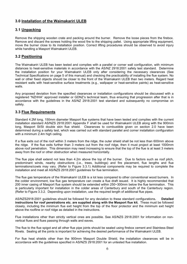
3.3 Flue Requirements Standard 4.2M long, 150mm diameter Masport flue systems that have been tested and complies with the current installation standard AS/NZS 2918:2001 Appendix F shall be used for Waimakariri ULEB along with the 900mm long, Masport St/St double skin flue shield. Clearances to combustible given on section 2.0 have been determined during a safety test, which was carried out with standard parallel and corner installation configuration with a minimum 2.4m high ceiling. If a flue exits out of the roof within 3 meters from the ridge, the outer shield shall be not less than 600mm above the ridge. If the flue exits further than 3 meters out from the roof ridge, then it must project at least 1000mm above roof penetration. This dimension may need increasing to ensure that the top of the flue is at least 3 meters away from the roof or other obstruction when measured horizontally. The flue pipe shall extend not less than 4.2m above the top of the burner. Due to factors such as roof pitch, predominant winds, nearby obstructions (i.e., trees, buildings) and fire placement, flue lengths and flue terminations/cowls may vary. (Refer to Figure 3.3.1) Additional components may be required to complete the installation and meet all AS/NZS 2918:2001 guidelines for flue termination. The flue gas temperature of the Waimakariri ULEB is a lot less compared to other conventional wood burners. In the colder environment, low flue gas temperature can create a flue draft issued. It is highly recommended that 200 inner casing of Masport flue system should be extended within 250~300mm below the flue termination. This is particularly important for installation in the colder areas of Canterbury and south of the Canterbury region. (Refer to Figure 3.3.2. Depending upon installation, use the required length of additional flue pipes. AS/NZS2918:2001 guidelines should be followed for any deviation to these standard configurations. Detailed instructions for roof penetrations etc. are supplied along with the Masport flue kit. These must be followed closely, including the minimum flue exit height from the top of the floor protector and the minimum exit height above the roofline or roof ridge as detailed in the instructions. Flue installations other than strictly vertical ones are possible. See AS/NZS 2918:2001 for information on non-vertical flues and flues passing through walls and eaves. The flue to the flue spigot and all other flue pipe joints should be sealed using firebox cement and Stainless-Steel Rivets. Sealing all the joints is important for achieving the desired performance of the Waimakariri ULEB. For flue heat shields other than the 900mm Masport Double Shield, the installation clearances will be in accordance with the guidelines specified in AS/NZS 2918:2001 for an untested flue installation.
7
Figure 3.3.1
3.4 Floor Protector Requirements The Waimakariri ULEB can be installed on any non-combustible ash floor protector with minimum dimensions given on page 4 if this manual. Please note that the dimensions given are minimum, and we recommend using a slightly larger floor protector size. Please note that the Waimakariri ULEB is heavy, having a total weight of 155 Kg. The floor and the materials used as floor protector should be strong enough to bear this load. The minimum requirements for material to be used as floor protectors on a combustible material are
- 6mm fiber cement board (e.g., Hardies Tile & Slate Underlay) plus 8mm ceramic tiles on a firm base. - 4mm mild steel floor protector supplied by Glen Dimplex - Or equivalent.
3.5 Reducing Clearances The clearances to combustible specified in section 2.0 of this manual, can be safely reduced by following guidelines specified in AS/NZS 2918:2001 table 3.1 & 3.2.
- Heatshield should be made of non-combustible material like metal or masonry. - Installed between the burner and the combustible wall - With an air gap behind it and vented top and bottom - The shield should extend a minimum of 450mm beyond the top of the appliance and extend width-wise so
that unshielded rear clearance is maintained
Clearance factors for heat shield which is within 45 degrees of the vertical
Heat Shield Construction Minimum Air Gap Dimension Clearance Factor
Single-layer of continuous material 12mm 0.4
Single-layer of continuous material 25mm 0.3
Two spaced layers of continuous material 12mm+12mm 0.2
Clearance factors for heat shield which is more than 45 degrees off the vertical Heat Shield Construction Minimum Air Gap Dimension Clearance Factor
Single-layer of continuous material 12mm 0.8 Single-layer of continuous material 25mm 0.6
8
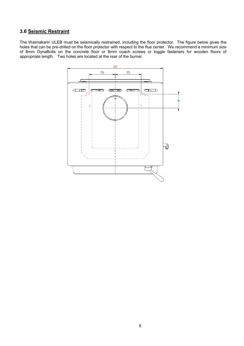
3.6 Seismic Restraint The Waimakariri ULEB must be seismically restrained, including the floor protector. The figure below gives the holes that can be pre-drilled on the floor protector with respect to the flue center. We recommend a minimum size of 8mm DynaBolts on the concrete floor or 8mm coach screws or toggle fasteners for wooden floors of appropriate length. Two holes are located at the rear of the burner.

9
3.7 Preparing the Burner for First Light-up The Catalytic Combustor, Stainless Steel Flame Arrestor Plate, and Masonry bricks are packed loose and separately along with the main burner. These items need to be installed carefully to make the burner ready for use.
Glen Dimplex highly recommends NZHHA trained SFAIT (Solid Fuel Appliance Installation technician) installer for installation of Waimakariri ULEB and carrying out the following initial set up. Step 1 – - Install Bricks in the following configurations. - First, install two x 208 long cut bricks on the rear wall of the firebox by locking under the brick retainer. - Then install one x 250 long full brick on each left and the right side wall of the firebox on its side edge. Push these bricks towards the rear of the firebox. - Lastly, install one x 123 long cut brick each on the left and right side wall towards the front of the firebox.
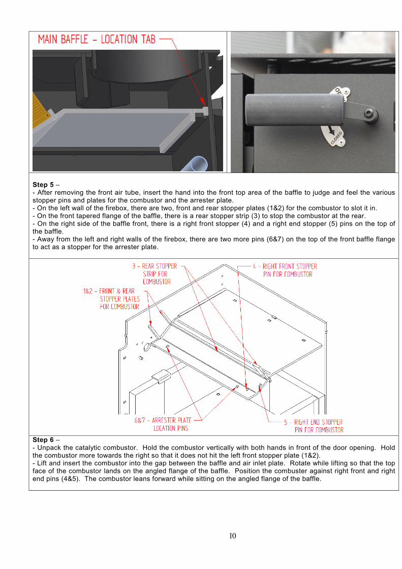
Step 2 – - The baffle is already in place. Check that the baffle is locked in place by trying to move it front to back, there is a location tab at the rear which locks it in place, and there should be no more than a couple of mm’s movement. Step 3 – - The front and the rear air tubes are already in place. The front tube needs to be removed to fit the catalytic combustor in place. - Remove the R-clip of the front air tube. - Slide the tube towards the right to unhook the left tab from the pin. Drop and slide the tube on the left side to remove the tube from the firebox. Step 4 – - Gently lift the damper handle to the “OPEN” position and leave in that position.
10
Step 5 – - After removing the front air tube, insert the hand into the front top area of the baffle to judge and feel the various stopper pins and plates for the combustor and the arrester plate. - On the left wall of the firebox, there are two, front and rear stopper plates (1&2) for the combustor to slot it in. - On the front tapered flange of the baffle, there is a rear stopper strip (3) to stop the combustor at the rear. - On the right side of the baffle front, there is a right front stopper (4) and a right end stopper (5) pins on the top of the baffle. - Away from the left and right walls of the firebox, there are two more pins (6&7) on the top of the front baffle flange to act as a stopper for the arrester plate.
Step 6 – - Unpack the catalytic combustor. Hold the combustor vertically with both hands in front of the door opening. Hold the combustor more towards the right so that it does not hit the left front stopper plate (1&2). - Lift and insert the combustor into the gap between the baffle and air inlet plate. Rotate while lifting so that the top face of the combustor lands on the angled flange of the baffle. Position the combuster against right front and right end pins (4&5). The combustor leans forward while sitting on the angled flange of the baffle.
11
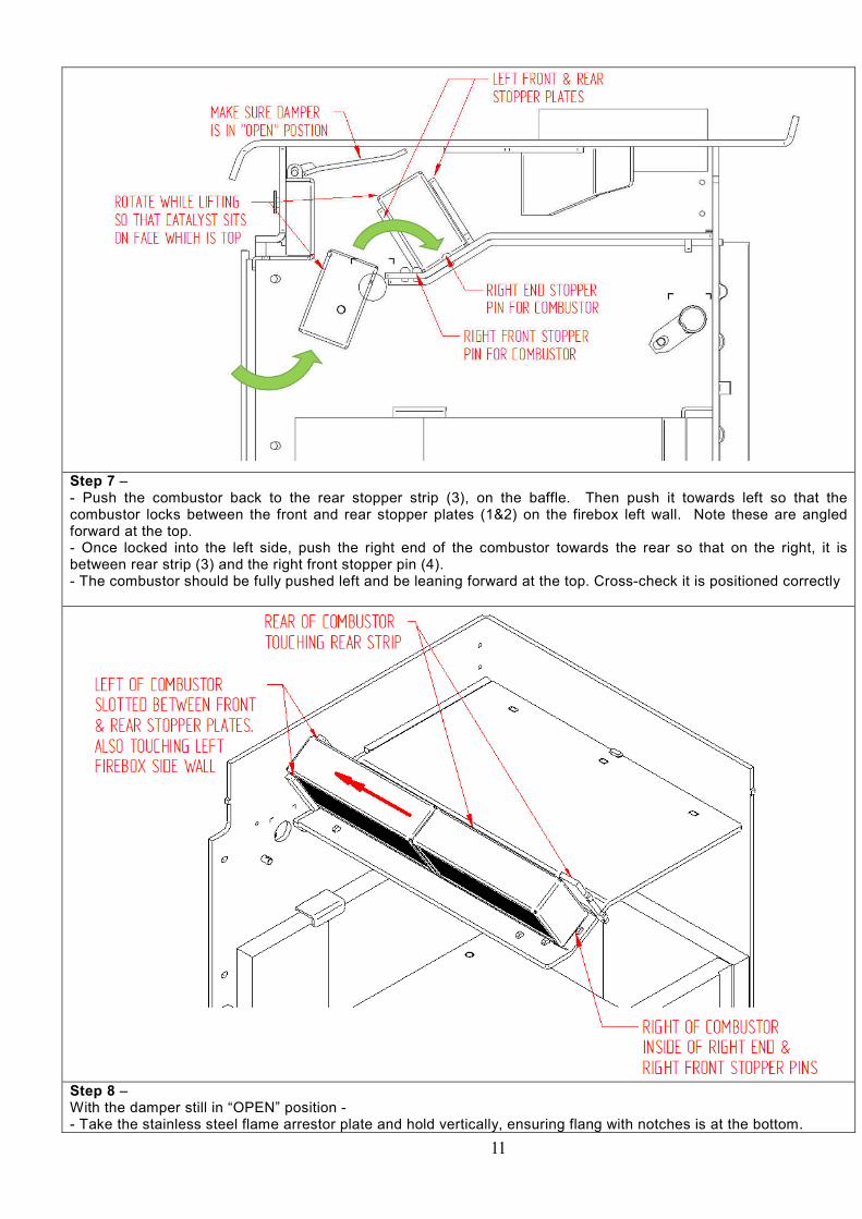
Step 7 – - Push the combustor back to the rear stopper strip (3), on the baffle. Then push it towards left so that the combustor locks between the front and rear stopper plates (1&2) on the firebox left wall. Note these are angled forward at the top. - Once locked into the left side, push the right end of the combustor towards the rear so that on the right, it is between rear strip (3) and the right front stopper pin (4). - The combustor should be fully pushed left and be leaning forward at the top. Cross-check it is positioned correctly
Step 8 – With the damper still in “OPEN” position - - Take the stainless steel flame arrestor plate and hold vertically, ensuring flang with notches is at the bottom.

12
- Lift the arrestor into the baffle gap until it hits the damper plate. Then position the bottom of the plate onto the front edge of the baffle.
- Push the plate to the left and the rear. Make sure that the plate nothches locate on two location pins (6&7) on the baffle front flange and the top of the arrestor plate is resting on the rear of the front air deflector.
Step 9 – - Reinstall the removed front tube. - Insert the without tab end of the tube into the hole on the right wall of the firebox. Tilt and lift the tube till the tab on the tube can be engaged with the pin on the left wall of the firebox. - Weave the R-clip into the small hole on the pin on the right. - Ensure that the tube is secured by pushing the tube both towards left and right. Step 10 – - Refer schematic below to check the configuration of all internal firebox components.
Before the first light-up, make sure that the burner is correctly installed and signed off by an approved installer. All local council’s wood fire permission or permit requirements have been completed satisfactorily.

13
4.0 Permitted Fuels The quality of the firewood you burn can have a considerable effect on the performance of the Waimakariri ULEB. Moisture content, tree species, and log size are the main factors that affect the emissions that are produced by any wood burner. The Waimakariri ULEB is designed to burn wood fuel that meets the following criteria:
- Less than 25% moisture content - Has not been treated with preservatives or impregnated with chemicals or glue - Is not chipboard, particleboard, or laminated board - Is not painted, stained or oiled - Is not driftwood or other salt impregnated wood
Burning materials that do not meet the above criteria can damage the firebox and put you at the risk of voiding the warranty of the Waimakariri ULEB. In NZ, radiata pine or macrocarpa is the most commonly available softwood species that are suitable as firewood. Other hardwood species like eucalyptus (bluegum) can also be mixed with softwood to achieve longer burns. If you are cutting your firewood, only wood that has been air-dried in a sheltered, well-ventilated stack, preferably for at least 12 months, maybe burned in the Waimakariri ULEB. To ensure that the wood has a moisture content of 25% or less, store it under a roof or protected against heavy rain. If you purchase firewood, buy firewood that is well seasoned and having moisture level below 25%. We recommend “Good Wood” merchants approved by your local council. Do not burn coal, driftwood, treated or painted wood, highly resinous wood, such as “Old Man’s Pine,” plastic, plywood, chipboard, garbage, flammable fluids such as gasoline, naphtha, engine oil, refuse, milk cartons, colored or printed paper. The combustion of such materials can emit toxic, corrosive, and hazardous fumes that will pollute the environment.
4.1 Testing Your Wood Moisture There are several ways to confirm if the wood is dry enough.
- The wood moisture meter is the best way to check the moisture content of the wood fuel. Split a piece of wood and then press the metering prongs firmly into the long side of a split piece to test moisture content. 15-20% percent of moister content is ideal.
- If you are purchasing firewood, ask for dry seasoned wood and get it tested from your wood merchant. - Dry wood weighs much less than wet wood. - Wet wood is hard to light and will emit moisture from the ends while burning. - Two dry pieces banged together sound hollow, and wet pieces sound solid and dull.
4.2 Recommended Log Sizes & Fire Starters - A packet of matches or lighter - A packet of firelighters. We recommend green firelighters made of wood waste - Seasoned firewood about 240~270mm long in various sizes
o (3.2A) For kindling - 15-16 finely split, dry softwood (total 1.0 kg approximately) o (3.2B) For intermediate 1 load – 4 pieces (total 1.2 kg, 300 g each approximately) o (3.2C) For intermediate 2 loads – 4 pieces (total 2.5 kg, 625 g each approximately) o (2D) For main load – 3 or more pieces (Total 3.0 kg, 1.0 kg each approximately)
3.2A 3.2B 3.2C 3.2D
Using well-seasoned firewood is key to maintain and improve the life of catalytic combustor.

14
5.0 Operational Sequence (For various steps refer images shown in the bracket) 5.1 Before First Light-up - Make sure that all the packing material has been removed from the combustion chambers. - Make sure the catalytic combustor and stainless steel flame arrestor plate are installed correctly. Please note that the special high-temperature paint is used in the firebox that will emit some smoke as it cures during the initial two to three sessions of running. Ventilate the house during these initial burns. While curing the surface, heated paint softens, so do not touch hot surfaces during this process. Babies, small children, pregnant women, elderly persons, persons subject to pulmonary hypersensitivity, and pets should avoid exposure to this smoke. Open doors and windows and use a fan, if necessary. After these initial burns, there should be no smoke.
5.2 Cold Startup 5.2.1 Initial light-up with kindling and intermediate load
1. Gently lift the damper handle and set it to the “OPEN” position and the air slide to the “HIGH” position. 2. Stack the intermediate load made of 4 small size logs, at the base of the firebox. 3. Stack around 15-16 very small kindling pieces on top of these logs. This initial light up procedure is the
“Top-Down Start-Up” method, which reduces the particle emission during the start-up phase considerably.
4. Place the firelighters on top of kindling and light the fire. We recommend green firelighters made of wood waste.
(1) (2) (3) (4)
5.2.2 Intermediate load 2 5. Keep the door ajar slightly. 6. Close the door approximately after 10 mins making sure that the kindling is well alight. Do not change
the damper or air slide position at this stage. At this stage, the combustion gases are passing over the combustor and pre-heating it.
7. After 15~17 mins, once the small logs are more than 50% burnt, open the door to add 2nd intermediate load, i.e., 4 pieces of medium firelogs. Close the door and continue to lite the fire on the “HIGH” air slide setting.
8. After 20~22 mins, gently turn the damper handle to the “CLOSE” position. By now, the combustor will be preheated to the required temperature. Closing the damper will divert all combustion gases through the combustor only. The combustor will start glowing in a few mins.
(5) (6) – 10 mins (7) – 15~17 mins (8) – 20~22 mins
DO NOT LEAVE BURNER UNATTENDED DURING THIS INITIAL LIGHT-UP PERIOD ALWAYS SWITCH DAMPER TO “OPEN” POSITION BEFORE OPENING THE DOOR

15
5.2.3 Main load and controlling output
9. Around 40~45 mins, when the intermediate load 2 is burnt more than 50%, switch the damper to the “OPEN” position and open the door for loading the main load.
10. Add 3 large size logs and close the main door. 11. Once the main load is fully lit, switch the damper to “CLOSE” positions. 12. Once the large size logs are fully alight, the burner is ready to adjust the output by operating the air slide.
At this stage, the burner combustion is stabilized, and catalyst is active and unburnt particles in the combustion gases are getting burnt while passing through the glowing combuster
13. Adjust the air slide to the medium of low position to control the output.
(9) – 40+mins (10) (11) (12)
Always open the door in three stages : 1. Switch the damper handle to “OPEN” position, air slide to “HIGH” setting and
wait for at least 30 secs 2. Unlatch the door and keep it slightly ajar for 15~20 seconds 3. Then open the door fully.
Always switch the damper handle gently and gradually. This practice is important to avoid puff of smoke coming into room or damage to the catalytic combustor.
5.2.4 Refueling and Shut-down
14. Before opening the door for reloading, make sure that the damper handle is switch to the “OPEN” position and air slide is on the “HIGH” setting. Reload one or two logs at a time. After reloading, keep the air slide to the “HIGH” position and keep damper “OPEN” till logs are fully alight.
15. To shut down the burner, let the fire extinguish and leave the burner doors closed until it has cooled down
DO NOT EVER USE THE BURNER WITHOUT
THE CATALYTIC COMBUSTOR AND FLAME ARRESTOR PLATE.
Note – The timing given for various steps of the light-up process may vary slightly depending upon wood, log length. After a couple of burns, the user will be able to judge for themselves.

16
6.0 Catalytic Combustor 6.1 How it works The Waimakariri ULEB uses a catalytic combustor to reduce emissions more effectively and control burn rates. This combustor is fitted in the front top portion of the firebox, above the front baffle in the exhaust gas stream. This combustor is made of thin high-grade stainless steel sheets encased in a thicker outer body and is coated with a hi-tech chemical composition. The particles within the combustion gases burn off when they pass through this coated combustor.
6.2 Best practices to enhance the life of catalytic combustor The catalytic combustor is the most critical part of the Waimakariri ULEB. The following precautions must be taken while operating the Waimakariri ULEB. - Always use well-seasoned natural firewood. Read section 4.0 carefully for permitted wood fuels for the
Waimakariri ULEB. Never use wet, painted, highly resinous, or driftwood. Never burn garbage or plastic material.
- Keep the damper open until the catalytic combustor becomes sufficiently hot (approximately 20~25 mins). During the start-up phase, the lower firebox temperature creates a larger volume of unburnt particles. These particles will tend to adhere to the combustor’s surfaces due to insufficient temperature. If the damper is closed during start-up, these may block the combustor and make it less efficient.
- Avoid leaving the door open for a long period. Too much air will cool the combustion process and the flue,
which can result in the combustion gases spilling out of the door. - Always make sure that the stainless steel flame arrestor plate is installed in front of the combustor. Direct
exposure of flames to combustor can damage the overall integrity of the combustor. - Regular monitoring and cleaning of the combustor are essential to maintain the combustor’s integrity and
effectiveness. Read the following sections 6.3 & 6.4 for monitoring and cleaning of Waimakariri catalytic combustor.
- Handle your combustor with care – Take care while handling the combuster so as not to damage the
combustor plates as this could reduce the flow through the combustor.

17
6.3 Inspection of the Catalytic Combustor
CAUTION: Inspect the combustor only when the burner is cold. The catalytic combustor used in the Waimakariri ULEB should be inspected periodically to ensure that it is not clogged and or damaged. A non-functioning combustor will affect heating efficiency and will increase emissions. Soot or darker granular material generated due to improper operation or poor quality fuel can lead to clogging of the combustor. Reduced heat output or sluggish performance are typical signs of clogging. The following are the steps to monitor and check the condition of the combustor periodically: 6.3.1 Visual Inspection while running the fire - During regular operation, when the main load of big fire logs is fully alight, ensure the damper is in the
“CLOSE” position. This fully stabilized state is achieved around 40~60 mins. You can see the catalytic combustor glowing parts through the perforated flame arrestor plate. To avoid exposure to radiating heat from the door, we recommend using a mirror from a lower level to view the glowing combustor.
- The glowing combustor is a sign of combustor working. - Also, note that at the end of the burn cycle, the combustor may not glow as there will be no combustibles in
the burner to activate the catalyst. - If the combustor does not glow during normal operation, go to the next step 6.3.2 Visual inspection by removing the flame arrestor plate - Using the tool provided with the Waimakariri ULEB, remove the flame arrestor plate and inspect the
combustor with the help of a small torch. - If the surface of the combustor is clean without any signs of clogging with fly ash or creosotes, put back the
flame arrestor plate and continue to use the burner and look for other signs. - If there are visible signs of clogging, Use methods described in section 6.4 to clean the clogged combustor. - If the clogging is due to tarry or granular brown substance, use the “Hot Burn technique” described in section
6.5 to burn off the clogging.
6.4 Removal of Catalytic Combustor - The first step is to remove the flame arrestor plate. Use special tool supplied with your burner to remove the
flame arrestor plate. Insert the tool into the holes which are at the center of the flame arrestor plate and push the plate upwards. Alternatively, you can use a medium-size flat screwdriver.
- Slowly push the plate upwards so that it disengages from it’s locating tabs on the front baffle and dangles vertically on the tip of the tool.
- Gently lower it down out of the firebox and keep it in a safe place. - Next, remove the front air tube. - Remove the R-Clip on the left. Then push the tube towards the right to disengage the tab. - Tilt and drop down the tube from the left side, till it comes out of the hole on the right of the firebox. - Next, put two hands inside and over the catalytic combustor. - First, push the combustor towards the right so that it comes out of left stopper plates fully. - Then roll it through 900 in the forward direction on the baffle flange. Gently pull it forward till it tips over the
front edge of the front baffle. Care should be taken so that the combustor does not dropdown. - Once tipped over, slowly and gradually take it out of front baffle and front air deflector gap. Keep it on a flat
surface for inspection and cleaning.
6.5 Cleaning of Catalytic Combustor Normally the catalytic combustor in the Waimakariri requires little or no maintenance. It generates high temperatures when active and therefore is self-cleaning. However, should the combustor becomes covered with soot or creosote, it can be cleaned using the following methods. Method 1 – In-situ Cleaning using a brush - If the combustor mesh is covered or filled up with fly-ash, use a paint-brush or soft-bristled brush and dust the
combustor. - Never use a wire brush or anything abrasive. Never use high-pressure air to clean as this may damage the
fine plates of the combustor.

18
Method 2 – In-situ Cleaning using a vacuum cleaner - Use a vacuum cleaner in low to medium suction mode to remove any build-up of fly-ash accumulated on the
surface of the combustor. - Never use high pressured air to blow the cells of any build-up. It can damage the cell walls. Both methods 1 & 2 should be attempted without removing the combustor from the burner. Remove the combustor for closer inspection only if the “Hot Burn” technique doesn’t burn off all the clogging. Method 3 – “Hot Burn” technique - Make sure that natural, good quality, dry wood fuel is used for this process. - Light up burner following steps in section 5.0. - After loading the main load, i.e., 2~3 large logs are well alight continue to keep the air slide on “HIGH”
positions for 10~15 mins. This process will create a ‘Hot’ fire. - Position the damper handle midway between OPEN & CLOSE position and keep it burning with this setting
for 30~40 mins. - The clogged particles will burn off during this Hot-Burn period and will help to clean the clogged combustor.
Never use cleaning solvents or spray to clean catalytic combustor. It can damage the combustor and other parts of the Waimakariri ULEB. The use of such a method will void the warranty of the Waimakariri ULEB.
6.6 When to replace the catalytic combustor The Waimakariri catalytic combustor will degrade with use and will need to be replaced accordingly. The life of the combustor will depend upon usage, type of fuel burnt, and care taken during operations and maintenance.
Major signs of an aged combustor - Lack of performance
- Less output - Increased fuel consumption
- Visual deterioration of the combustor plates. - Visual increase in emissions Before concluding that the combustor needs replacement, ensure that you are using your burners with all the tips given in section 6.2. Mainly the correct fuel and the damper operation. Further, inspect the combuster carefully by following steps in section 6.3 & 6.4 and if needed, clean the combustor by following steps in section 6.5 The ultimate and important way to check the status of the combustor is to check emissions coming out of your chimney. You can get an indication of whether the catalyst is working by comparing the amount of emissions leaving the chimney when exhaust gases are going through the combustor, i.e., when damper is “CLOSED,” to the amount of emissions leaving the chimney when the emission is routed over the combustor, i.e., when the damper is “OPEN.” For checking emissions, strictly follow the procedure given below:
- Make sure that natural, good quality, dry wood fuel is used for this process. - Light the stove by the following instruction in section 5 and run it for at least 80~90 mins - Load a couple of large size logs and wait for few mins till they are alight. - Switch the damper to the “OPEN” position, go out and observe the emissions leaving the chimney. - Switch the damper to the “CLOSE” position and again observe the emissions leaving the chimney.
Significantly less emissions are expected when the damper is in the “CLOSE” position. - Follow the above steps at least 2~3 times before contacting your dealer for replacement.
Follow steps 4, 5 & 6 outlined in section 3.7 to replace the combustor.
A non-functioning combustor should be replaced with a new catalytic combustor
sourced from Glen Dimplex New Zealand.

19
6.7 Conditions of Catalytic Combustor Waimakariri combustor pictures in different states:
New combustor
Combustor
fitted inside the
firebox
Flame
arrestor plate
installed
Glowing
combustor inside the
firebox
The tool provided
for removal of
arrestor plate
Damaged combustor
Clogged
combustor

20
6.8 Maintenance of Other Waimakariri Parts Further sections will describe the systematic process of carrying out servicing of different parts of the firebox, and flue. Replace parts only with genuine GLEN DIMPLEX spare components:
1. Door and other seals 2. Firebox bricks & Baffle 3. Flue inspection and cleaning
6.8.1 Door and Other Seals Door seals of the main door should be checked and, if required, will need replacement periodically depending upon the usage of the Waimakariri ULEB.
Do not operate the burner If the door seal is damaged or missing. Excessive air input can cause overfiring and damage burner parts, including vital catalytic combustor. If any part of the burner or flue system is glowing, the burner is being over-fired.
6.8.2 Firebox Masonry Bricks The masonry bricks in your Waimakariri ULEB are an important part of the burner to achieve clean and efficient burn. These bricks are likely to degrade with time and will need to be replaced accordingly. The life of the bricks will depend upon usage, type of fuel burnt, and care taken during operations and maintenance. The bricks are held in place using the brackets welded to the firebox sides and the rear. Due to the high temperature in the firebox, the bricks may crack with use, and this is regarded as a normal occurrence. If the bricks crack but remain in place, it will not affect the performance of the fire and subsequently can continue to be used. The bricks should be replaced only when they are damaged enough in place and cannot perform their intended task. Refer section 3.7 for location and sequence of assembly of bricks in the firebox of the Waimakariri ULEB. After removing the old bricks, remove all the ash from the firebox by removing the ash plug and collect it in the ash drawer using a brush. For pedestal or leg models, scoop out the ash using a suitable tools. Refer Step 1 in section 3.7, for replacing the old bricks.
6.8.3 Flue Inspection & Cleaning Flue system should be checked at least once a year depending upon usage and, if needed, be swept by a professional chimney sweep. Do not use chemical chimney cleaners. Check the flue sections nearest the firebox. If a flue system is becoming excessively blocked or needs frequent cleaning, investigate the installation, fuel, and operation of the burner with the help of a professional. Refer section 6.4 for carrying out the following steps: - Remove the flame arrestor plate using the special tool provided - Remove the front and the rear air tube - Remove catalytic combustor. - To remove the baffle, lift and tilt the baffle from either left or right side till it sides off the side baffle supports.
Bring it down within the firebox and then take it out of the door at an angle. - This will enable to drop and collect all the chimney dirt into the firebox without removing the main flue pipe. Once chimney sweep operation is complete, clean the firebox chamber properly and put back the baffle, rear air tube, catalytic combustor, flame arrestor plate, and the front tube.

21
7.0 Waimakariri Replacement Parts Some parts of the Waimakariri ULEB are considered consumable. These parts will wear out or degrade over time. The life of these parts will vary upon - How frequently the fire is used - Type of fuel. Some species of wood fuel are harsher than others. Following items are considered as consumables: Bricks - Set of masonry bricks for the main combustion chamber or firebox. Seals Main Door Seal Catalytic combustor related parts - Catalytic Combustor - St/St Flame Arrestor Plate - Damper plate & lifting mechanism - Baffle - Front air deflector - Front Air Tube - Rear Air Tube Glass - Main Door Glass Other Spare Parts/Kits available - Damper Handle Kit - Main Door Handle Kit These consumable parts should be replaced as soon as they show signs of wear. Running your burner with worn or broken parts may result in reduced output, an increase in fuel consumption, and even can damage the firebox or other vital parts of the burner. We highly recommend a frequent visual check of these consumables and other parts of the burner. Refer to the schematic below of various Waimakariri parts.

22
8.0 Problem Solving
Problem Reason for Problem Solution Dark, dirty film on the door glass
Burning wet or green firewood OR Leaking door seals.
Ensure only dry seasoned wood is used. As per the new air plan, it is an offense in the Environment Canterbury region to burn wood with greater than 25% moisture. Check the door and glass seals. Your Masport Dealer can help with this. To remove dirty film try following: 1. Burn with the damper open for 30 minutes. 2. Try to clean glass with damp newspaper and
ash when the fire has completely cooled down
3. Try using non-caustic oven cleaner Caution: Do not scrub using steel products or abrasive material, as it can leave scratch marks on the glass and damage printing on the glass.
Smoke entering room due to extreme negative pressure in the house
Such a situation will occur when the air circulates down from the chimney towards the interior of the house, which is at negative pressure. Energy efficiency practices and new building code rules are making our houses increasingly airtight. These practices make the house’s energy-efficient but also makes them more sensitive to negative pressure when air is exhausted from the house. The reasons can be because of large extraction fans, which cause extreme negative pressure in the house when they are operating. This negative pressure works against the flue system draft. In severe cases, the negative pressure in the house overcomes the flue system draft, and the appliance begins to spill smoke, especially when a fire is started or when it dries down to coals. Also, it can starve fire from air needed resulting in poor performance.
To prevent this extreme negative pressure, open a window approximately 6mm to allow combustion air to enter the room. If this doesn’t work carry out visual inspection of combustor by following steps in section 6.3
The poor performance of the fire – not enough heat or drop in output
Number of causes can result in less output 1. Green/wet wood or inappropriate fuel
2. Burner operated with the damper in
“OPEN” position 3. Combuster not functioning
1. Use seasoned wood. Refer Section 4 for details of appropriate fuel and testing fuel. Run the burner a couple of times using correct fuel and steps given in section 5.2
2. It is important to “CLOSE” the damper when the burner has reached a sufficiently hot temperature. Refer section 5.2 and follow correct start-up, loading and re-fuelling steps
3. Follow the steps in section 6.3 and carry out
the visual inspection of the combuster. Also, ensure that tips in section 6.2 are followed. If the combustor is found to be clogged, follow steps in section 6.4 to clean the combustor.

23
Run the burner again using correct fuel and steps given in section 5.2
Increased consumption of fuel
1. Burner operated with the damper in “OPEN” position
2. After extensive use of the combustor or use of inappropriate fuel, the combustor will lose its efficiency to generate extra heat.
1. It is important to “CLOSE” the damper when the burner has reached a sufficiently hot temperature. Refer section 5.2 and follow correct start-up, loading and re-fuelling steps
2. Carry out visual inspection and cleaning of combustor by following section 6.3, 6.4 & 6.5.
Check emission coming out of your chimney by following steps in section 6.6 Consult your dealer about the other possible causes

24

25
GLEN DIMPLEX WARRANTY REGISTRATION WAIMAKARIRI ULTRA LOW EMISSION BURNER
Thank you for purchasing a Masport Fire. We ask you to complete the following information and return to the Glen Dimplex Warranty Registration Department on the following address: New Zealand : P O Box 58473, Botany, Manukau 2163, Auckland Australia : Unit 1, 21 Lionel Road, Mount Waverley, Victoria 3149 Mr / Mrs / Miss / Ms Name: _______________________________________________
Address: ________________________________________________________________
_________________________ Post Code: ___________________________
Telephone: _________________________ Fax: ________________________________
Email ________________________________________________________________
Model: _________________________ Serial Number: ________________________
Retailer: _________________________ Purchase Date: ________________________
Price: ________________________________________________________________
Installed By: _________________________ Date Installed: _________________________
We at Glen Dimplex strive to provide you with quality products and have a continuous product development program. To help achieve our objectives to our mutual benefit, we would welcome your feedback on the following questionnaire.
Question Please tick appropriate remark
1.General presentation of Product □ Excellent □ Good □ Ok □ Needs to Improve 2.Styling and Looks □ Excellent □ Good □ Ok □ Needs to Improve 3.Packaging □ Excellent □ Good □ Ok □ Needs to Improve
4.Is documentation easy to follow and informative?
□ Excellent □ Good □ Ok □ Needs to Improve
5.Fixtures & Fittings (Loose parts) □ In order □ Items missing □ Needs to Improve 6.Do you currently own Masport or Dimplex product?
□ Yes □ No Which? -
7.Why did you decide on Masport? (tick one or more options)
□ Knew this brand □ Suggested by Friend □ Dealer recommended □ Better Price □ Performance □ Features
8.Other Comments
Privacy Act Notice: the owner named on the Warranty Registration consents and agrees that Glen Dimplex may retain and use the information in this warranty card, including details about the owner for marketing and development purposes. The owner also agrees that Glen Dimplex may also share purposes with [intended recipients of such information]. In accordance with the New Zealand Privacy Act 1993 and the Australian Privacy Act 1988, the owner shall have the right to request the correction of, as well as inspect, all personal information held by Glen Dimplex on that owner.
------------------------------------------------------------------------------------------------------------------------------ Please cut and mail this completed form within 30 days of installation to your
Glen Dimplex Warranty Registration Department at the above address
Cut H
ere
C
ut H
ere
C
ut H
ere

26

27
WARRANTY FOR MASPORT WAIMAKARIRI ULTRA-LOW EMISSION BURNER (PED, ASH & LEG Versions)
This warranty is provided in New Zealand by Glen Dimplex New Zealand Ltd and in Australia by Glen Dimplex Australia Pty Ltd. (together referred as “Glen Dimplex”) This warranty is provided to the first domestic purchaser of a Masport Waimakariri Ultra-low Emission Burner. It applies from the date of purchase from or through an authorized Masport Fire Distributor in relation to each product or component for the period below.
During the warranty period, Glen Dimplex will repair or replace (at its option) any Masport Wood Fire, which is found to be defective in materials or workmanship. Repairs will be carried out by an approved Masport Heating Service Agent. What is covered under this warranty?
Repair or replacement of parts Labor costs relating to the Wood Burner Reasonable transport or travel costs.
Consumers may have additional rights under the Consumer Guarantees Act 1993 (New Zealand) or the Australian Trade Practices Act 1974, including the Australian Consumer Law. Conditions
This warranty does not apply and will be void where: The Wood Burner is not installed in accordance with AS/NZS2918/:2001 or any building
code or consent; The Wood Burner is not installed by a qualified specialist installer; Any electrical work has not been carried out by a Registered Electrician; The Wood Burner has been moved and reinstalled, or has been modified in a manner
that is not consistent with the Installation Guide or the Owner's Manual; The Wood Burner has not been installed, operated, or maintained according to the
Installation and Operations Manual; The Wood Burner is acquired for business use in any way.
PARTS LABOUR
BURNER's STEEL FIRE BOX 20 10
RAKAIA CATALYTIC COMBUSTOR &
DAMPER RELATED PARTS * 2 1
DOOR GLASS & SEAL 2 1
MASONRY BRICKS 2 1
GLEN DIMPLEX FLUE SYSTEM 2 1
* REFER SECTION 7 ON PAGE 21, FOR LIST OF PARTS
28
What is not covered?
Labor costs relating exclusively to components not manufactured by Glen Dimplex. Damage caused by incorrect use or the burning of treated or painted wood, driftwood or
other fuels which are not recommended; Travel costs for a distance greater than 50 km from the nearest approved Masport
Heating Service Agent. (The location of the Wood Fire must be advised to Glen Dimplex or its sales agents at the time of purchase or using warranty registration form)
Defects, malfunctions, or failures caused by incorrect installation, poor installation, normal wear and tear, misuse, neglect, accidental damage, or failure to follow operating instructions in the Owner's Manual (including fuel selection, product operation and maintenance instructions), repairs or modifications by persons not authorised by Glen Dimplex, use of parts not supplied by Glen Dimplex, or damage or other events which have occurred since the product left the control of Glen Dimplex.
Direct, indirect, or consequential losses or special damages of any kind (including costs of collection and delivery) other than repair or replacement of products or components under this warranty, where any goods are acquired or used for the purposes of a business;
How to obtain warranty service?
Completed Warranty registration form (previous page) needs to be mailed within 30 days of installation to your Glen Dimplex Warranty Registration Department.
Warranty Claims must be made at the place of purchase.
Reasonable proof of purchase date is required to make a warranty claim. You should
keep your purchase receipt.
Warranty repair will be completed according to the normal work practices of the service
agent.
Make the faulty part(s) available to Glen Dimplex for inspection so that the validity of the
claim can be established by them.
Manufactured in New Zealand by:
GLEN DIMPLEX NEW ZEALAND LTD
NZ Registration No – 1506305
P.O. Box 58473, Botany,
Manukau, Auckland 2163
Phone: 0800 666 2824
Fax : 09 274 8472
Email : [email protected]
Web : www.glendimplex.co.nz
*Glen Dimplex New Zealand Ltd reserves the right to change specifications, the content of this manual or the design of its product without prior notice.