welcome to the airah sa technical seminar ‘lessons learnt
TRANSCRIPT

Welcome to the AIRAH SA Technical Seminar
‘Lessons Learnt From Commissioning HVAC’
Presented by:Richard Cooper, AM.AIRAH – Air Con Serve
Alek Wcislo – A G O’Connor

LESSONS LEARNT FROM COMMISSIONING CONTROLS
Richard Cooper

• Things are not Ready– Power is not available– The plant is not wired– It’s not plumbed up
Not installed as per the specification. Been installed as per the specification and still does not work. Been value managed by the managing contractor and the mechanical contractor
and something fundamental is now missing.• Impossible Schedule.
– The Managing Contractor allocated us 2 weeks to do 8 weeks worth of commissioning.
• 1 week before handover they are still building the building.• Meters are Modbus when they are supposed to be LONworks.• We have pressure controlled laboratories to commission and the building is not
sealed.• WE HAVE ALL BEEN THERE AND WHY DOES THIS HAPPEN?
What Affects Commissioning
Rio Olympicshad to cancel Cycling tests as Velodrome
not ready

• Preparation for commissioning should start from the moment you receive a purchase order.– You must have this philosophy.– If you install what is specified and just let everyone do their own thing, the job
will not commission well.– If you do the above, and you cut costs, you will be lucky to ever get out of the
project.
If you coordinated the trades and make sure what you are installing is engineered to work, the project will commission faster.
Commissioning time is Money. Achieving completion on time is good.
LET’S LOOK AT HOW TO AVOID THESE THINGS

• DX A/C systems are oversized and cannot control evenly and effectively. • Pumping equipment is sized so marginally that motors fall of their curves.• Fans are already at 100% speed and have no room to speed up as HEPA filters get dirty
and PC2 Rooms are not sealed.• Light load chillers are selected with compressors larger than the smallest compressor on
the duty chiller.• Buffer Tanks are not installed or are too small on chilled water systems
So what are the most common problems ACS are finding with systems that we go to commission?

• Headers or Heat Separating Buffer Tanks are piped incorrectly.• Cooling tower Nozzles are not selected correctly.• Cooling towers have incorrectly size balancing lines.• Cooling/Heating Coils are too close to each other in de-humidification applications.• Air distribution is not even, in particular the areas with ceiling based return air, are over
heating, stratification is occurring, and they are not warming up.
So what are the most common problems ACS are finding with systems that we go to commission? Cont’d

• An over sized DX unit is just as bad as an undersized DX unit. • Oversized single compressor or dual compressor units will short cycle.• They will over cool & over heat, dump cold air or stratify hot air and will make the
occupants very unhappy.• As much as everyone will try and blame the BMS there is nothing we can do with an
oversized unit to stop complaints, unless the units were selected with variable or digital Scroll compressors and still they, need to be sized correctly.
DX A/C Systems are oversized and cannot control evenly and effectively
Note we have done some projects with some Temperzone digital scrolls selected correctly and we can control the condensation levels on test tubes in laboratories.

• Designers fall for this all the time.• It just seems that not enough time is being given to working out the actual
Best Efficiency Point and too many jobs are designed so marginally or using exactly what was specified, that we are hitting the run-out point where we are off the curve.
Pumping equipment is sized so marginally that motors fall off their curves
The wrong Pump size. Will reduce the project efficiency. Slow down commissioning. Cost Money to fix.

• Fans like pumps need to be sized with spare capacity, so be proactive and size with some spare.
• Be astute get on the builders early, and warn them that they need to seal the space, door frames, GPOs and light fittings.
• Too much time is being lost during commissioning because people just are not aware how these areas react.
• This adds cost to everyone involved.
Fans are already at 100% speed and have no room to speed up as HEPA filters get dirty and PC2 Rooms are not sealed

• We now have quite a few projects where this has happened, and it is not a good outcome.
• We have seen chiller providers even quote jobs this way.
• Not enough engineering is being done.• Price base decisions are made with out checking.• Basically the client ends up purchasing an oversized
backup machine that will not ever run as intended, and save energy.
• So check the supplier's selections. • Run the compressor sizing past the controls engineer
who is going to write staging for strategy for the chillers.
Light load chillers are selected with compressors larger than the smallest compressor on the Duty Chiller.
Light Load Chiller
Duty Chiller

• A buffer tank is not a Minimum volume tank so do not get the 2 confused.
• Minimum Volume is the amount, set by the manufacturer, that a chiller needs to pass to achieve its Minimum on cycle time with out faulting.
• Where as a buffer tank must be sized to maintain the system Leaving Water Temperature when ever the chiller cycles off to maintain and protect the load.
Buffer Tanks are not installed or are too small on Chilled Water Systems
On Primary Only Systems the Buffer Tank should be located before the pump and chiller.

• On Primary / Secondary Chilled water systems, the buffer tank must be located in the decoupling line to work correctly.
• It is normally installed to ride out staging times between chillers starting and stopping.
Buffer Tanks in Primary Secondary Systems

• If your system flow is 1 LPS and your chiller cycles off for 15 minutes.
• Your Buffer Tank must be • 15Min x 60 Sec x 1 LPS = 900 Litres.• Any smaller and you will loose control of
the system when the chiller cycles off and effect the load.
• Not good when your system is serving a Hospital MRI Machine.
• So ask the supplier what is the maximum starts per hour for the chiller and work out the minimum off time to be applied to size an appropriate tank.
Sizing Buffer Tanks on Chilled Water Systems

• This problem is surprising as it is so basic but still gets piped incorrectly.• It is so simple heat rises and cold sinks.• Deliver the heat from the source to the top.• Take the heat from the top to the Load.• Deliver the cold return from the load to the bottom. • Pull from the bottom back to the heat source.• The opposite for Cooling.• Simple Physics.• But the industry still gets it wrong.
Heat separating Buffer Tanks piped incorrectly

• The CHW is going in and out too close together, and field supply is not being taken from the cold bottom of the tank.
• This system did not deliver all of the cold water to the field.• The final modifications were at great cost, and ensured that
cold went IN and OUT at the bottom, and warm went back to the tank and back to the chiller from the TOP.
• Please don’t get it wrong.
Cooling separating Tank piped incorrectly

• This header is piped correctly and will commission very well.• These systems can be initially commissioned without the BMS controls even being ready.
Primary / Secondary Headers Piped Incorrectly
The water mixes evenly from the chillers to the field.
It has TD and Magnetic flow meters for monitoring COP and flow in the primary, and energy and flow in the secondary.
All pumps are variable. You can achieve positive primary
flow by measuring the °C from decoupling sensor to ensure you are sending all the cold leaving directly to the field.
It has a turbulator on the return to allow even mixing back to the chillers.
It ticks all the boxes.

• Example 1 Primary Secondary Header that is difficult to commission.
Primary / Secondary Headers Piped Incorrectly
With one chiller running.
The water mixes Unevenly from the Chiller during load up and supplies half the field with cold water.
Building control is lost during staging and will take time to recover.

• Example 2 Primary Secondary Header that is difficult to commission.
Primary / Secondary Headers Piped Incorrectly
The secondary return does not go through a turbulator.
The water mixes Unevenly from the field.
The Chillers will always load unevenly unless the system is at full capacity.

• Example 3 Primary Secondary Header that is difficult to commission.
Primary / Secondary Headers Piped Incorrectly
The second chiller some times feeds on to itself with out having a chance of mixing with the first chiller.
The first chiller receives all of the load from the field.
Unless the system is at full capacity the Chillers will load unevenly.

• Primary Secondary CHW Systems with instruments, are good to commission and will provide ongoing energy savings.
Primary / Secondary Header Piped Correctly
In a correctly installed and designed, low loss primary / secondary common coupled header.
You do not have the induced pressure drops.
You can control the equilibrium of flow and temperature, in both the primary and secondary piping loops, to be only what is required, and optimise the building demands.
When these systems are piped correctly they commission very quickly.

• Often these days we like to couple the towers together and take advantage of low fan speed with natural adiabatic cooling to save energy.
• When cooling tower nozzles are not sized correctly for low flow we get dry patches on the tower fill material and the air bypasses the wet fill and the water does not get cooled.
• Nozzle selection should be designed to cope with low to maximum flow to allow full tower optimization and commissioning.
Cooling Tower Nozzles are not selected correctly
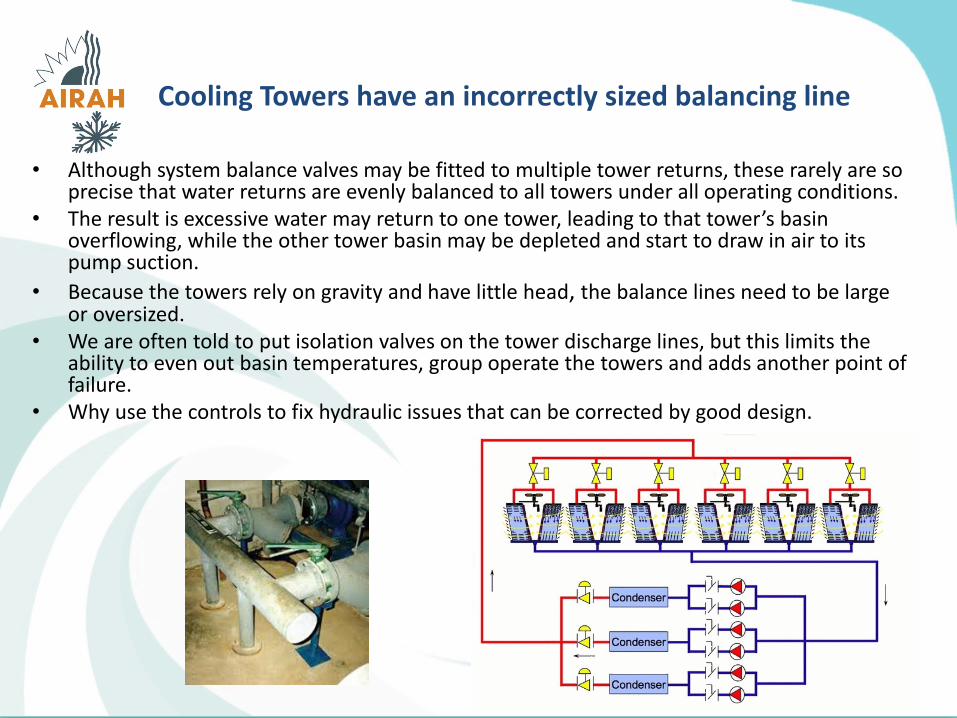
• Although system balance valves may be fitted to multiple tower returns, these rarely are so precise that water returns are evenly balanced to all towers under all operating conditions.
• The result is excessive water may return to one tower, leading to that tower’s basin overflowing, while the other tower basin may be depleted and start to draw in air to its pump suction.
• Because the towers rely on gravity and have little head, the balance lines need to be large or oversized.
• We are often told to put isolation valves on the tower discharge lines, but this limits the ability to even out basin temperatures, group operate the towers and adds another point of failure.
• Why use the controls to fix hydraulic issues that can be corrected by good design.
Cooling Towers have an incorrectly sized balancing line

• Too often we are finding that incorrect selections are being made for dehumidification applications.
• I have been involved in several jobs now, and when we go to commission the dehumidification control, we find the cooling coil is often too close to the heating coil.
• If the heating coil is going to warm the cooling coil by either conduction or radiated heat, you limit the ability to reach dew point and dehumidify.
• You need distance between the coils for any such system to work.• The coil arrangement needs the room for the condensate to settle and for heat
not to be transmitted back into the cooling coil.• Check what arrangement you are getting before you install?
Cooling/Heating Coils are too close to each other in de-humidification applications

• If you deliver air at 8 to 10°C hotter than space temperature, to a room with a ceiling return air path, even with the best diffusion, the air will tend to stratify, and you will loose a good percentage of the heat back out the return air.
• Whenever the room is colder than the supply air, the supply air will be buoyant and will rise after delivery.
• Cooler warm supply air will have more room penetration and heat the space better and faster.
• Typically 28°C to 30°C air will work better for a 22.5°C Setpoint.• Leaving Air sensors following any heating coil are essential for better
control.
Air distribution is not even, in particular areas with ceiling-based return air, are over heating, stratification is occurring,
and they are not warming up

• Analytics is the hot topic at the moment in regard to BMS systems and Fine Tuning Mechanical Plant.
• Basically as we see it Analytic Rules are applied to a BMS system to try and find problems that could be causing plant to run incorrectly or could be wasting energy.
• Analytics come in two forms.– Part of a BMS system either built in, or an add on to the main BMS software.– Independent to the BMS operated by a 3rd party and the reads information from a
BMS system using BACnet High Level Interface protocol, or from trend information written to a separate Windows SQL Server.
– There are a lot of people getting into this you would have heard or seen the term, BIG DATA.
When coupled with Cloud Storage this can be a powerful tool.
ANALYTICS / COMMISSIONING

• Initially we were against independent Analytics companies attaching themselves to our BMS systems.
• We had the attitude that, “what are they going to find if we have set it up properly in the first place”.
• And this can be true, BUT it was not until an INDEPENDANT Analytics company put their system on some of our sites and some of our oppositions sites that the real picture came in to play.
• Our BMS sites came up almost clean.• When the Oppositions BMS site did not.• Further the Analytics started confirming some of the mechanical issues that we
had also highlighted on these sites.• We concluded 3rd party Data Analytics can find BMS and Mechanical faults quite
well.
ANALYTICS / COMMISSIONING

ANALYTICS / COMMISSIONING
We feel analytics in some form will keep moving forward with BMS systems. Clients may choose to enter into long term analytics contracts with either there trusted
incumbent BMS contractors or select an Independent analytics contractor. The more Data that is brought into a BMS system the more benefit analytics will be to
the client. You can’t analyse what is not measured. Some essential items to be measured for analytics are proving to be.
Leaving Air Sensors. Multi function meters, the more the better. Temperature difference and flow on CHW and HW systems to calculate Coefficients
of performance COP. CO2 and air quality Levels. Even Humidity

• When BMS systems are installed on a budget you only get what you pay for.• The same with Mechanical systems.• We know of at least 3 significant buildings, in Adelaide, where we have been asked to
review an oppositions BMS, that has been deemed uncommissioned.• How does this happen, I think we know?
– They were screwed to a ridiculous price, – The project was design and construct with impossible deadlines. – The building was occupied before the commissioning was fully finished, access
became difficult – The list goes on.
• The fact is we were smashed price wise, on all of these building at tender, and I truly believe this is because we allowed more hours to commission.
• The industry has tried to prevent this from happening by adding the independent commissioning agent, and in some cases this has been very successful.
ANALYTICS AS A COMMISSIONING TOOL

• We think however the independent commissioning process could be taken a step further by Introducing the Independent commissioning Analytics Agent.– Hired by the client and engaged at the beginning of the design period.– Oversees the way the building must perform.– Works with the Mechanical and BMS contractors during design.– Activates a third party analytics package at practical completion.– Highlights what is not operating correctly or needs tunning during the
defects liability period. A BMS contractor that always allows the instruments and hours to commission
correctly, will have no problem working with this. A BMS contractor who does not allow the instruments and hours, as a result of
this process, will soon start allowing to do so. It is very important that this Agent is not working for the Managing contractor,
the Mechanical contractor or the BMS contractor. They work for the Client to make sure the system is what was the Client paid
for and is commissioned as intended.
ANALYTICS AS A COMMISSIONING TOOL

If you coordinated the trades and make sure what you are installing is engineered to work, the project will commission quicker.
• Take more time to review plant that is selected that is application specific and think about the ongoing operation and commissioning.
• Data Analytics is the way of the future and we believe if applied during construction will improve the whole industry to a level where projects are commissioned correctly.
SUMMARY

MECHANICAL SERVICES COMMISSIONING
PROCESS
CHALLENGES
AND LESSONS LEARNT
Alek Wcislo

PRESENTATION OVERVIEW
• WHAT IS MECHANICAL SERVICES COMMISSIONING
• COMMISSIONING STAGES
PLANNING EXECUTION AND DELIVERABLES
• CHALLENGES
• LESSONS LEARNT

WHAT IS MECHANICAL SERVICES COMMISSIONING
is a quality process focused on enhancing the delivery of a project.
The process focuses upon verifying and documenting that the facility and all of its systems and assemblies are planned, designed, installed, tested, operated, and maintained to meet the Owner's Project Requirements.
COMMISSIONING THEN
• Air and Water Balance
• Air/Water Balance Sheets
HVAC Commissioning by ASHRAE definition
AND TODAY…
• Early planning
• More methodical
• ICA
• Green Star and NABERS
• Complete as installed documentation
• Handover

… and Who and Why benefits from Commissioning…
• Fewer call backs• Customer satisfaction, trust and confidence• Service DLP within budget
Building Owner ?
Contractor ?
Builder ?
• Comprehensive TAB of equipment• Complete commissioning documentation• Building operation to intended design • Functionality testing of equipment and controls• Occupant’s comfort conditions• Problems identified early and rectified • Improved building efficiency• Lower maintenance cost
Community ?
WHAT IS MECHANICAL SERVICES COMMISSIONING
• Ability to deliver complete project to customer
• Better system efficiency• Lower green gas emission

Initial Commissioning, occurs during construction of a new building or on a new HVAC system within an existing building.
Three types of Commissioning
WHAT IS MECHANICAL SERVICES COMMISSIONING
Re-commissioning is commissioning of HVAC systems that were already commissioned at construction but the owner wants to verify, improve and document their performance
Retro-commissioning commissioning focused on fixing notorious problems of existing buildings, improving efficiency of plant and reducing running costs

NEBB Australia, working under licence from NEBB USA is an organisation dedicated to the implementation and promotion of established industry standards, procedures and specifications for work in the various disciplines related to environmental systems. Established in 2006 has now over 140 NEBB Professionals and Technicians in Australia and New Zealand
• Commissioning conducted as per NEBB or eg. CIBSE requirements
• Calibrated instrumentation and equipment
• NEBB technicians undergo continuous training
• Proven “in action” commissioning procedures
• Networking
… and why NEBB?
WHAT IS MECHANICAL SERVICES COMMISSIONING
• Consultant specified NEBB commissioning

COMMISSIONING PROCESS
• COMMISSIONING PRELIMINARIES
• PRECOMMISSIONING
• ELEMANTAL COMMISSIONING
• SYSTEM COMMISSIONING
• FUNCTIONAL AND PERFORMANCE TEST
• PROJECT HANDOVER

PRELIMINARIES
RESOURCES
• Commissioning Team – Internal e.g. water balance and air balance teams, MechElec and BMS
• Commissioning Team – External e.g. water treatment, HEPA Filters, Thermal Plant… non-HVAC Systems…
DOCUMENTATION
• Mechanical Specification• Standards and Regulations• For Construction Drawings, Schematics• BMS Functional Description• Commissioning Procedures - Project Specific• Commissioning SWMSs – Project Specific• Equipment Technical Data, fan/pump curves etc• Fire Matrix• Commissioning Report Proformas• COMMISSIONING PLAN !!!
COMMISSIONING PROCESS

COMMISSIONING EQUIPMENT AND INSTRUMENTATION
• Duct Air Leakage Test Rig
• TAB Instrumentation Air and Water
• Temperature and Humidity
• Other as required (refrigeration, rotation, sound meter…)
• CALIBRATION CERTIFICATES !!!…
COMMISSIONING PROCESS

PRECOMMISSIONING
• CONSTRUCTION ITPs – construction team
• CHW and HHW PIPE PRESSURE TEST – HVAC plumbers)
• DALT – DUCT AIR LEAKAGE TESTING
• EQUIPMENT PRE-COMMISSIONING
• AIR DISTRIBUTION SYSTEM PRECOMMISSIONING
• WATER SYSTEM PRECOMMISSIONING
• CONDITIONS PRECEDENT• Builders Works Complete – zone safe to work in• MSSBs Commissioned and COC-ed• Mechanical Works (ductwork, air diffusion installed, piping, equipment installed• Control Valves, Dampers Point to Point Tested
COMMISSIONING PROCESS

DALT
• AS 4254.2:2012 Testing of systems >3000 L/s is mandatory
• Minimum of 10% of duct systems to be tested
• Testing involves construction and commissioning teams
• Recent projects prove rising awareness among installers and improved installation standards
• Test Equipment and Instrumentation
• Duct Leakage impacts on: • energy efficiency• greenhouse gas emission • system performance • commissioning progress
COMMISSIONING PROCESS

ELEMENTAL COMMISSIONING
• AHUs, FCUs, Fans, Evap. Coolers etc… Initial Set-up and Start-up
• Pumps, Make-up units, VSDs, Initial Set-up and Start-up
• DX Systems
• Non-HVAC Plant e.g. Fume Cupboards, CRAC Units, HEPA filters
• Duct Heater Banks, Humidifiers
• Cool Rooms, Cold Rooms, Freezer Rooms
• Thermal Plant: Chillers, HHWUs, Heat Exchangers
COMMISSIONING PROCESS

SYSTEM COMMISSIONING• Air Balance
• Commissioning procedure customised and project specific
• Water Balance• Commissioning procedure customised
and project specific
• Thermal Plant Integration• Involves Mechanical Services, BMS and
Plant Commissioning Crew
• Non-HVAC Systems• Compressed Air and Lab Gases• Fume Cupboards
• Fire/Smoke Management Systems• AHU/Fans Plant and Systems• Stair Press• Smoke Exhaust• Smoke Dampers
COMMISSIONING PROCESS

FUNCTIONAL AND PERFORMANCE TESTS
• Smoke/Fire Management System Commissioning
• Thermal Plant Functional and Performance Testing
• Air and Water Distribution Systems• System optimisation• Operating Set Points
• Trendlogs
COMMISSIONING PROCESS
• System Automation and Tuning

PROJECT HANDOVER
• Plant and Systems Statutory Certification• Chillers, Air/Gas Receiver: Pressure Vessels• HHWUs and Boilers: appl. Type “B”• NATA Certification: HEPAs, Fume Cupboards• Electrical and Gas COCs
• O&M manuals
• Final Witnessing
• System Monitoring and Data Logging
• Handover Training
COMMISSIONING PROCESS

COMMISSIONING FLOW DIAGRAM - sample
COMMISSIONING PROCESS

FIRE/SMOKE MODE COMMISSIONING
• Significant mile-stone in commissioning process
• From simple Fire Shutdown to Complex Fire/Smoke Management System Commissioning
CHALLENGES
• Very challenging… physically and mentally
• Certificate of Occupancy depends on Fire/Smoke Management System Commissioning
• Requires coordinated planning and involves many trades
• Fire Matrix• Fire-Mechanical Services-BMS Interface Testing• Functional Testing (Fire Matrix)• Operation of non-HVAC plant and equipment (e.g. Smoke Curtins, gas shutdown etc…)• Performance Testing
• Stair Press Systems, • Smoke Exhaust Systems, • Operation of AHUs/Fans etc…

CONSOLIDATED FUNCTIONAL COMMISSIONING
• Close cooperation with BMS contractor
• … and how important it is for the building owner to take over functionally tested HVAC systems?
CHALLENGES
• Needs development of Specific Functional Test Schedule
• At the end of construction process… no time allocated by builder
• Often “dragged over” PC date into DLP

MANAGEMENT ISSUES
• Fire testing poorly coordinated
• ITPs not followed
• PtoP testing incomplete
• Poor communication between trades
• No time for proper functional/performance commissioning
• For Construction documentation not followed by subcontractors• Working of superseded drawings, equipment schedules…• Electrician installed wrong size O/Ls, VSDs…• BMS contractor selected wrong control valves…
• Duct contractor poorly managed e.g. balancing to start now and no registers fitted
CHALLENGES

INSTALLATION ISSUS
• ACCESS • ACCESS • ACCESS
• Incomplete building and HVAC works
• Poor Workmanship• Duct joints leaking• Plastic foil left in ductwork
• Crossovers….Most Notorious• Pipes• Ducts• Control and/or Balancing Valves installed back to front• Temperature Sensors• VRF Systems – Piping and Controls Wiring
• CTRL/Balancing Valves• not enough straight pipe up/downflow• no ID Tags, poor access to binders
CHALLENGES
• Equipment, dampers, valves…

DESIGN/ENGINEERING ISSUES
CHW-HHW-CW SYSTEMS
• Undersized expansion vessels –excessive system static pressure
• Undersized by-pass valve, or oversized without balancing valve
• No Low Load Chiller
• CHW Loop – insufficient loop volume, no buffer tank… chiller will short-cycle
CHALLENGES
• Buffer Tank – no bypass installed

DESIGN/ENGINEERING ISSUES
CHW-HHW-CW SYSTEMS
CHALLENGES
• STAD-STAF valves oversized – line size – need to be engineered
• PICC Valves selected at near max setting – no margin left
• CTRL Valves kv – select 25mm valve…
• CHW System – how to control Pump Speed and By-Pass Valve ?

AIR DISTRIBUTION SYSTEMS
• VAV registers used in constant flow systems
• Different type registers make balancing difficult
• Swirl diffusers, adj. geometry diffusers - wrong selection, installed incorrectly causing noise, draft…
• Flow Control Air Valves – selected with small margin
• Fire dampers – curtain in flat ducts – restricts flow
• FCUs with V-belts in ceiling space – not a great idea
• No branch dampers
CHALLENGESDESIGN/ENGINEERING ISSUES

DESIGN/ENGINEERING ISSUES
AIR DISTRIBUTION SYSTEMS
• AHUs with adjustable pulleys and VSDs ???
• AHUs with Plug Fans • Fan Effect no allowance for
pressure drop• Duty stand-by• No manual 0-10 V signal
• FCUs sized for Cooling with excess AirFlow
CHALLENGES
• Fans - poor inlet conditions
• Mission Impossible Ductwork

DESIGN/ENGINEERING ISSUES
AIR DISTRIBUTION SYSTEMS
CHALLENGES
• R/A Path not though of…
• Undersized Flex/cushion heads
• Balancing Damper installed in cushion head
• Undersized O/A duct not picked at in-house engineering
• Fan Assisted or Not - O/A path
LESSONS LEARNT
• Most of those issues are PREVENTABLE
• Commissioning Crew to start on site Not Too Early Not Too Late
• Enforce DALT testing, duct risers in particular
• Pre-commissioning is vital to successful outcome
• Early involvement; eg examination of for construction documentation, access…
• Push PMs to execute ITPs
• Manage regular commissioning meeting
• Ensure ALL subcontractors working of up to date drawings, equipment selections…

• Fire Mode Test Coordination needs to start early and involve ALL participants
LESSONS LEARNT
• Suction diffusers – work well, remove fine mesh after preclean
• Enforce Cleaning Strainers
• VRF System – Commission ONE at a time
• CW system commissioning can start only when Water Treatment is available
• Access to BMS speeds up commissioning process eg. VAV boxes
• By-Pass Valve – install away from chillers
• Air/Dirt Separators seem like a good idea

Thank you for your attention