what’s new? - synthmind · beep codes ... displayed error messages..... 74 glossary ... •intel...
TRANSCRIPT

What’s New?
User’s Manual Revision 2.x corresponds to S1832DL motherboardrevision B as indicated in the corner of the board near the DIMM slotsand IDE ports.
We have added a glossary to our manuals and have expanded ourinstallation guide. We think you will find both more thorough, andthoroughly helpful. Our simple but accurate glossary explanations makeit possible for the most novice of end users to understand the technicaljargon that pops up in these pages. The numerous pictures in the step-by-step installation guide make it easy for you to put together yoursystem without help from technical support personnel.
Don’t like an explanation? Want to see terms explained that we left out?Have any other comments? Visit the TYAN web page and let us knowabout it at www.tyan.com/html/contacts.html

Table of Contents
1. Introduction...........................................................................4Overview........................................................................ 4Icons.............................................................................. 5Hardware Specifications/Features................................... 6Software Specifications...................................................8Technical Support...........................................................8Returning Merchandise for Service................................ 9Trademarks.................................................................. 9
2. Board Installation.............................................................. 10Unpacking....................................................................10Installation....................................................................10Setting Jumpers.............................................................25
3. Onboard Resource Settings.............................................. 26Quick Reference for Jumpers........................................26Map of Motherboard Jumpers....................................... 27Soft Power Connector.................................................. 31Speaker Connector Installation...................................... 31Hardware Reset Switch Connector Installation............... 31External SMI............................................................... 32Chassis Intrusion Alarm Connector................................ 32CMOS RTC................................................................. 32Flash EEPROM........................................................... 33Hardware CMOS & Password Reset............................ 33RAM Installation.......................................................... 33Cache Memory.............................................................35Frequently Asked Questions.......................................... 35
4. BIOS Configuration........................................................... 38Standard Setup............................................................. 40Advanced Setup........................................................... 45Chipset Setup............................................................... 50Power Management Setup............................................ 56PnP/PCI Setup............................................................. 60Peripheral Setup........................................................... 64

Supervisor and User Security.........................................67Anti-Virus Security....................................................... 68Detect IDE Utility.........................................................69Language Utility........................................................... 69Flash Writer Utility........................................................ 69
5. System Resources............................................................. 72Beep Codes................................................................. 72Troubleshooting System Problems.................................. 73Displayed Error Messages............................................ 74Glossary....................................................................... 76
http://www.tyan.com
4
Chapter 1Introduction
Overview
The S1832DL Tiger 100 is a quality, high performance mainboarddesigned for dual Intel Pentium II microprocessors. This mainboardutilizes the Intel 440BX AGPset and can support CPU speeds of233MHz through 450MHz, and host bus speeds of 66MHz to 100MHz.
The S1832DL mainboard, with built-in AGP slot, provides high perfor-mance capabilities that are ideal for a wide range of demanding appli-cations such as CAD, CAM, CAE, desktop publishing, 3D animation,and video production.
This integrated system board achieves high reliability with numerousfeatures and yet is small enough to be supported in an ATX formfactor. Some of the features included are onboard dual channel PCIPIO, Bus Master IDE and UltraDMA/33, onboard floppy controller,and onboard high speed I/O.
Flexibility and expandability have been designed into the Tiger 100.With I/O and drive controller support built onboard, the one AGP slot,
chap
ter 1
Introduction
http://www.tyan.com
5
INT
RO
five PCI and two ISA slots (one shared, seven usable slots) are freefor numerous add-on expansion cards.
Remember to take a look at TYAN Computer’s web site located athttp://www.tyan.com. There you can find information on all of TYAN’sproducts along with FAQs, distributors list, drivers, and BIOS settingexplanations.
Icons
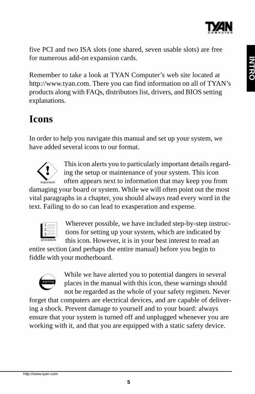
In order to help you navigate this manual and set up your system, wehave added several icons to our format.
This icon alerts you to particularly important details regard-ing the setup or maintenance of your system. This iconoften appears next to information that may keep you from
damaging your board or system. While we will often point out the mostvital paragraphs in a chapter, you should always read every word in thetext. Failing to do so can lead to exasperation and expense.
Wherever possible, we have included step-by-step instruc-tions for setting up your system, which are indicated bythis icon. However, it is in your best interest to read an
entire section (and perhaps the entire manual) before you begin tofiddle with your motherboard.
While we have alerted you to potential dangers in severalplaces in the manual with this icon, these warnings shouldnot be regarded as the whole of your safety regimen. Never
forget that computers are electrical devices, and are capable of deliver-ing a shock. Prevent damage to yourself and to your board: alwaysensure that your system is turned off and unplugged whenever you areworking with it, and that you are equipped with a static safety device.
!important!
procedure
1.2.3.
warning
http://www.tyan.com
6
Chapter 1Introduction
Hardware Specifications/Features
Processor Information •Two SEC slots (Slot One type).•66 to 100MHz BIOS selectable bussupport.•Pentium II 233-450MHz.•Supports Celeron CPU (single only).
Chipset Information •Intel 440BX AGPset.•Intel PIIX4e controller.•National 309 Super I/O chipset.
Voltage and Power •ATX power supply connector.Information •+12V power source for DC fan
onboard.•3.3V DRAM support.•Utilizes GTL+ bus to reduce powerconsumption and EMI.
Main Memory •Up to 1024MB onboard.•Four 168-pin DIMM sockets.•Supports 100MHz SDRAM withSPD.
System Management •National LM79 and LM75ASICs with onboard alarm formonitoring temperature,supplyvoltages, and fan speed.•Intel LANDesk Client Managersoftware•Chassis intrusion detection capable.
Expansion Slots •One 32-bit AGP slot.•Five 32-bit PCI Bus Master slots.•Two 16-bit ISA slots.
http://www.tyan.com
7
INT
RO
•One shared, seven usable slots.
Physical Dimensions •ATX design.•12 inches x 9.8 inches.•Requires Intel Venus compatible I/Oshield.
BIOS Information •AMI Plug and Play flash BIOS.•Deep Green, Energy Star, ACPI,Year 2000, and PC98 compliant.•Soft power-down, multiple bootoptions.•Win98/NT5 ready, DMI 2.0compliant.•PCI 2.1, APM 1.1 compliant.
Disk Drive & System I/O •Two PCI bus mastering EIDEchannels.•Supports EIDE CD-ROMs.•PIO Mode 3 & 4 (up to 17MB/secDTR).•UltraDMA/33 bus mastering mode(up to 33MB/sec DTR).•Support for two floppy drives (up to2.88MB).•Two serial ports (16550 UARTs).•One ECP/EPP parallel port.•One IR (InfraRed) I/O interface port.•Two USB rev 1.2 (universal serialbus) connectors.•One PS/2 mouse connector.•One PS/2 keyboard connector.
Warranty •3 year manufacturer’s warranty.
http://www.tyan.com
8
Chapter 1Introduction
Software Specifications
OS •Operates with MS-DOS, Windows3.x, Windows for WorkGroup 3.x,Windows 95, Windows 98, WindowsNT, OS/2, Novell Netware, Solaris,and SCO Unix.
Information presented in this publication has been carefully checked forreliability. However, no responsibility is assumed for inaccuracies. Theinformation contained in this document is subject to change withoutnotice.
Technical Support
If a problem arises with your system, you should turn to your dealer forhelp first. Your system has most likely been configured by them, andthey should have the best idea of what hardware and software yoursystem contains. Hence, they should be of the most assistance. Further,if you purchased your system from a dealer near to you, you canactually bring your system in to them to have it serviced, instead ofattempting to do so yourself (which can have expensive consequences).
If your dealer is unable to assist you,try our web page, http:// www.tyan.comuser newsgroup, alt.comp.periphs.mainboard.tyantechnical support phone line, (510) 440-8808or e-mail address [email protected]

http://www.tyan.com
9
Returning Merchandise for Service
During the warranty period, contact your distributor or system vendorFIRST for any product problems. This warranty only covers normalcustomer use and does not cover damages incurred during shipping orfailure due to the alteration, misuse, abuse, or improper maintenance ofproducts.
For Resellers Only:A receipt or copy of your invoice marked with the date of purchase isrequired before any warranty service can be rendered. You can obtainservice by calling the manufacturer for a Return Merchandise Authori-zation (RMA) number. The RMA number should be prominentlydisplayed on the outside of the shipping carton and the package shouldbe mailed prepaid, or hand-carried to the manufacturer. TYAN will payto have the board shipped back to you.
Trademarks
AMIBIOS is a trademark of American Megatrend Incorporated.Windows is a trademark of Microsoft Corporation.IBM, PC, AT, PS/2 are trademarks of IBM Corporation.INTEL, Pentium II, Celeron are trademarks of Intel Corporation.S1832DL Tiger 100 are trademarks of TYAN Computer Corporation.All other trademarks are the property of their respective companies.
INT
RO
http://www.tyan.com
10
Chapter 2Board Installation
chap
ter 2
Board Installation
Unpacking
The mainboard package should contain the following:· S1832DL mainboard· One IDE 40-pin cable· One 34-pin floppy cable· User’s manual· Two retention modules· One Tyan System Management & Driver CD
Installation
You are now ready to install your mainboard. The mounting holepattern of the S1832DL matches the ATX system board specifications.Your chassis should be that of a standard ATX mainboard form factor.

http://www.tyan.com
11
How to install our products right...the first time.
What’s the first thing I should do?The first thing you should do is read this user’s manual. It containsimportant information which will make configuration and setup mucheasier.
The next step is to properly ground yourself. First, unplug the powerfrom your computer case and then touch the metal casing of the powersupply or any metal part on the computer case. This will discharge anyelectricity from your body. Take the motherboard out of the cardboardbox and static bag, holding it by its edges, and place it on a groundedanti-static surface, component side up. Inspect the board for damage.
DO NOT APPLY POWER TO THE BOARD IF IT HAS BEENDAMAGED!
Press down on any of the socket ICs if it appears that they are notproperly seated (the board should still be on an anti-static mat). Do nottouch the bottom of the board. Remember, don’t take any electronicdevice out of its protective bag until you are ready to actually install itinto the computer case. If you don’t discharge yourself and you zap themotherboard or adapter card, problems may not arise immediatelybecause electrostatic discharge damage, unlike physical damage, causesthe device to fail over time.
Install the motherboard into your case.Follow the instructions provided by the case manufacturer for properinstallation guidelines. TYAN recommends that you use only one screwto hold down the motherboard. The rest of the mounting holes should beused for the plastic standoffs. If your case does not have a hole for astandoff, simply cut off the bottom of the plastic standoff so that the flatportion rests on the metal. The adapter cards and the screws holdingthem down will keep your board flat. The fastening screw should notshort any of the traces on the motherboard. Make certain that you donot overtighten the screw, as it will damage the motherboard andpossibly break internal traces in the surrounding area. The hole you
!important!
procedure
1.2.3.
INS
TALL
http://www.tyan.com
12
Chapter 2Board Installation
should use is located at the top-center of the board where the adaptercards are fastened to the case.
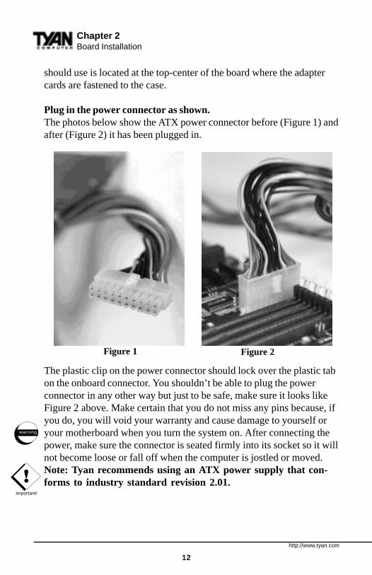
Plug in the power connector as shown.The photos below show the ATX power connector before (Figure 1) andafter (Figure 2) it has been plugged in.
The plastic clip on the power connector should lock over the plastic tabon the onboard connector. You shouldn’t be able to plug the powerconnector in any other way but just to be safe, make sure it looks likeFigure 2 above. Make certain that you do not miss any pins because, ifyou do, you will void your warranty and cause damage to yourself oryour motherboard when you turn the system on. After connecting thepower, make sure the connector is seated firmly into its socket so it willnot become loose or fall off when the computer is jostled or moved.Note: Tyan recommends using an ATX power supply that con-forms to industry standard revision 2.01.
Figure 1 Figure 2
!important!
warning
http://www.tyan.com
13
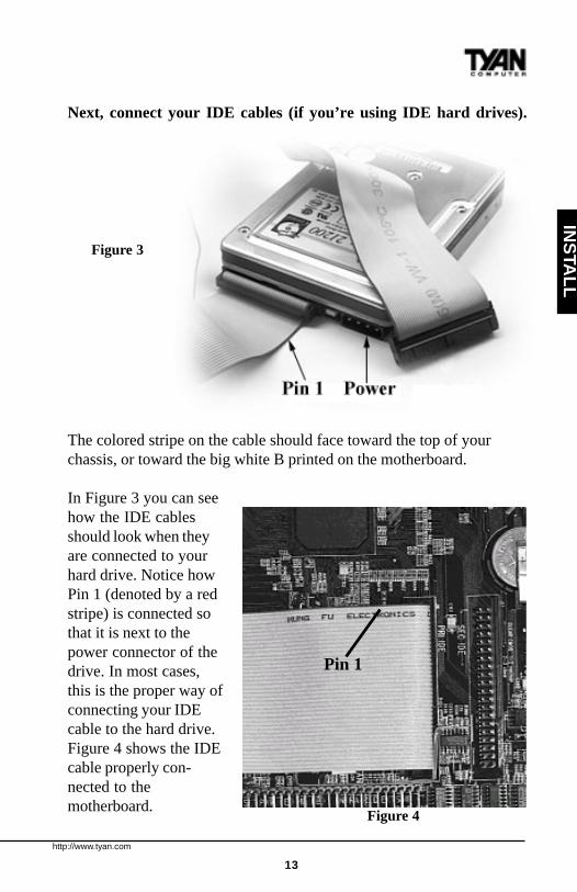
Next, connect your IDE cables (if you’re using IDE hard drives).
The colored stripe on the cable should face toward the top of yourchassis, or toward the big white B printed on the motherboard.
In Figure 3 you can seehow the IDE cablesshould look when theyare connected to yourhard drive. Notice howPin 1 (denoted by a redstripe) is connected sothat it is next to thepower connector of thedrive. In most cases,this is the proper way ofconnecting your IDEcable to the hard drive.Figure 4 shows the IDEcable properly con-nected to themotherboard.
INS
TALL
Figure 3
Figure 4
Pin 1

http://www.tyan.com
14
Contact your hard disk drive manufacturer or documentation for moreinformation.
Some symptoms of incorrectly installed HDDs are:• Hard disk drives are not auto-detected: may be a Master/Slave
problem or a bad IDE cable. Contact your vendor.• Hard Disk Drive Fail message at bootup: may be a bad cable or
lack of power going to the drive.• No video or beeps on bootup: usually means the cable is on
backwards.• Hard drive lights are constantly on: bad IDE cable or defective
drives/motherboard. Try another HDD.• Hard drives do not power up: check power cables and cabling.
May also be a bad power supply or IDE drive.
Now that you have installed your IDE drives, your floppies are next.
Pin 1 on the floppy cable is usually denoted by a red or colored stripedown one side of the cable (see Figure 5). Most of the current floppydrives on the market require that the colored stripe be positioned so thatit is right next to the power connector. In most cases, there will be a keypin on the cable which will force you to connect the cable properly.
Chapter 2Board Installation
Figure 5

http://www.tyan.com
15
Drive A: is usually attached to the end of the cable with the twist in it.Drive B: is usually connected to the middle of the cable. Refer to yourinstallation instructions or call your dealer if you are unsure aboutattaching floppy drives. Refer to Figure 5 on the previous page for adetailed anatomy of the floppy cable. Remember, you can only have 2floppy drives connected at any given time.
The color stripe on the cable should face toward the top of yourchassis, or toward the big white B printed on the motherboard. Pleaserefer to your documentation for proper installation, or see Figure 4 onpage 13.
Some symptoms of incorrectly installed floppies are:• Floppy drives are not detected: usually caused by faulty cables,
backward cables, or a bad floppy or motherboard. Try anothersingle floppy drive to verify the problem or try another cable. Also,check to see if the onboard floppy is enabled in the BIOS.
• Floppy Drive Fail message at bootup: the cable, floppy, ormotherboard may be faulty. Try another cable or floppy drive toverify.
• Light on the floppy is on constantly: a dead give-away that thecable is on backwards. Reverse the cable at the motherboard endand try again.
Next are the Com and Printer ports.
Warning: When plugging in your keyboard and mouse, or whenplugging anything into a serial or Com port, make sure that the power isoff. Connecting these devices and ports while the power is on is called“hot plugging,” and may damage your system.
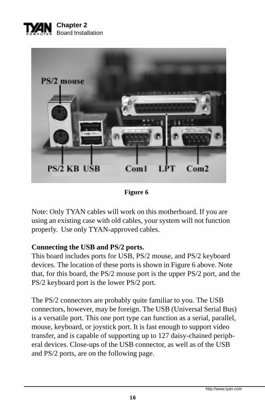
Figure 6 at the top of the next page shows the ATX double row connec-tors on this board. The Com and Printer ports, as well as the otherports, are labeled.
INS
TALL
!important!
http://www.tyan.com
16
Chapter 2Board Installation
Note: Only TYAN cables will work on this motherboard. If you areusing an existing case with old cables, your system will not functionproperly. Use only TYAN-approved cables.
Connecting the USB and PS/2 ports.This board includes ports for USB, PS/2 mouse, and PS/2 keyboarddevices. The location of these ports is shown in Figure 6 above. Notethat, for this board, the PS/2 mouse port is the upper PS/2 port, and thePS/2 keyboard port is the lower PS/2 port.
The PS/2 connectors are probably quite familiar to you. The USBconnectors, however, may be foreign. The USB (Universal Serial Bus)is a versatile port. This one port type can function as a serial, parallel,mouse, keyboard, or joystick port. It is fast enough to support videotransfer, and is capable of supporting up to 127 daisy-chained periph-eral devices. Close-ups of the USB connector, as well as of the USBand PS/2 ports, are on the following page.
Figure 6
http://www.tyan.com
17
INS
TALL
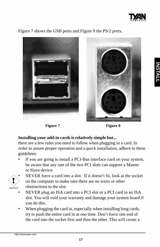
Figure 7 shows the USB ports and Figure 8 the PS/2 ports.
Installing your add-in cards is relatively simple but...there are a few rules you need to follow when plugging in a card. Inorder to assure proper operation and a quick installation, adhere to theseguidelines:• If you are going to install a PCI-Bus interface card on your system,
be aware that any one of the two PCI slots can support a Masteror Slave device.
• NEVER force a card into a slot. If it doesn’t fit, look at the socketon the computer to make sure there are no wires or otherobstructions to the slot.
• NEVER plug an ISA card into a PCI slot or a PCI card in an ISAslot. You will void your warranty and damage your system board ifyou do this.
• When plugging the card in, especially when installing long cards,try to push the entire card in at one time. Don’t force one end ofthe card into the socket first and then the other. This will create a
Figure 7 Figure 8
!important!

http://www.tyan.com
18
Chapter 2Board Installation
rocking motion between the card and the slot and it will damage thepins within the socket.
• Make sure that the cards are seated securely into the slots.• Before turning on the system, make sure no cards are touching
each other or are shorting.
If you follow these basic guidelines, there shouldn’t be any problemswith installation. However, if you do encounter any problems, have aqualified professional install your cards for you or contact your cardmanufacturer.
Remember, always read the manuals and installation notes that comewith the adapter cards. They contain important information which willhelp you install the components right, the first time.
Next, you need to install your memory.Since TYAN boards are manufactured with performance in mind, youshould use add-in components that match. Some DIMM modules mayseem to be high quality because of name or feel but that does notguarantee real-world usability. Some cheaper or OEM memory mayhave brand-name components, but they may be on inferior or substan-dard parts which do not meet the critical tolerances our productsrequire. Because of this, your memory may not work correctly in aTYAN board though it may work well in a competitor’s board. This isbecause many of our competitors do not adhere to the strict tolerancesrequired for high performance. If you buy a TYAN board, you aregetting the best system available. To make installation easy and troublefree, get high quality parts. Some brands we recommend are AdvantageMemory, Corsair Microsystems, Millenium, Kingston Memory, QesTecIncorporated, Unigen, Micron Technology, and Crucial Technology.These DIMMs have proven to be very stable on our boards and performextremely well.
http://www.tyan.com
19
INS
TALL
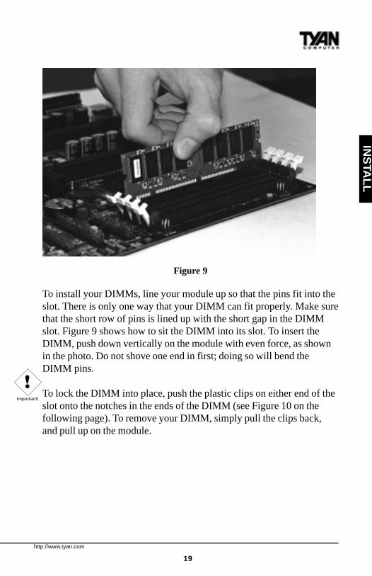
Figure 9
To install your DIMMs, line your module up so that the pins fit into theslot. There is only one way that your DIMM can fit properly. Make surethat the short row of pins is lined up with the short gap in the DIMMslot. Figure 9 shows how to sit the DIMM into its slot. To insert theDIMM, push down vertically on the module with even force, as shownin the photo. Do not shove one end in first; doing so will bend theDIMM pins.
To lock the DIMM into place, push the plastic clips on either end of theslot onto the notches in the ends of the DIMM (see Figure 10 on thefollowing page). To remove your DIMM, simply pull the clips back,and pull up on the module.
!important!
http://www.tyan.com
20
Chapter 2Board Installation
!important!
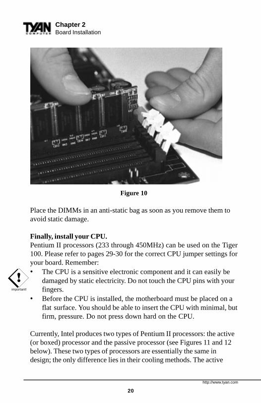
Figure 10
Place the DIMMs in an anti-static bag as soon as you remove them toavoid static damage.
Finally, install your CPU.Pentium II processors (233 through 450MHz) can be used on the Tiger100. Please refer to pages 29-30 for the correct CPU jumper settings foryour board. Remember:• The CPU is a sensitive electronic component and it can easily be
damaged by static electricity. Do not touch the CPU pins with yourfingers.
• Before the CPU is installed, the motherboard must be placed on aflat surface. You should be able to insert the CPU with minimal, butfirm, pressure. Do not press down hard on the CPU.
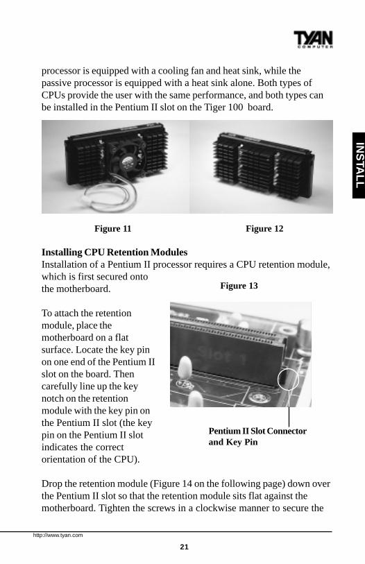
Currently, Intel produces two types of Pentium II processors: the active(or boxed) processor and the passive processor (see Figures 11 and 12below). These two types of processors are essentially the same indesign; the only difference lies in their cooling methods. The active
http://www.tyan.com
21
INS
TALL
processor is equipped with a cooling fan and heat sink, while thepassive processor is equipped with a heat sink alone. Both types ofCPUs provide the user with the same performance, and both types canbe installed in the Pentium II slot on the Tiger 100 board.
Figure 11 Figure 12
Installing CPU Retention ModulesInstallation of a Pentium II processor requires a CPU retention module,which is first secured ontothe motherboard.
To attach the retentionmodule, place themotherboard on a flatsurface. Locate the key pinon one end of the Pentium IIslot on the board. Thencarefully line up the keynotch on the retentionmodule with the key pin onthe Pentium II slot (the keypin on the Pentium II slotindicates the correctorientation of the CPU).
Drop the retention module (Figure 14 on the following page) down overthe Pentium II slot so that the retention module sits flat against themotherboard. Tighten the screws in a clockwise manner to secure the
Pentium II Slot Connectorand Key Pin
Figure 13

http://www.tyan.com
22
module to the board. Warning: Do notovertighten the screws as you may damagethe module and/or the motherboard.Installing the Active ProcessorWhen the retention module is securely in-stalled, you are ready to plug in the CPU.Press down firmly on the CPU until you heara “click” (see Figure 15). This clicking soundindicates that the CPU is fully locked into the retention module. If you
have an active processor, you will also need to con-nect the CPU’s cooling fan cable to the cooling fanpower connector on the board.
Locate the cooling fan connector (e.g. FAN1) on themotherboard. Plug the CPU’s cooling fan cable intothe cooling fan connector on the board. There will be aplastic clip assembly similar to that of the ATX powerconnector that will force you to connect the fan cablecorrectly (see Figure 16 below).
Figure 16
Figure 14
Figure 15
Chapter 2Board Installation

http://www.tyan.com
23
Installing the Passive ProcessorThe installation of the passive processor differs only slightly from thatof the active processor. Your passive CPU package should contain oneCPU retention module, one heat sink retention bracket with mountinglocks, two mounting attachments, and one heat sink lock.Install theretention module as explained in the active processor section.
The heat sink mount (Figure17) has two pins on thebottom and four pins on thetop. Notice that the bottomtwo pins are of differentsizes. The size of the pins and
the holes in the motherboard will determine the correct orientation.When the bracket is correctly installed, the four pins on top will be rightnext to the Pentium II CPU slot.
Insert the heat sink mount into the holes on the motherboard. When thebracket is properly inserted into the holes on the motherboard, you willhear a clicking noise.
Align the CPU with the CPU retention module. Make sure the heat sinkis lined up with the heat sink mount bracket. If you put the CPU in thewrong way, you may damage the CPU, the motherboard, and/or theCPU socket. Slowly press down on the CPU module until the CPUlocks into place. You will hear a clicking noise when the CPU is lockedsecurely into the module.
The heat sink lock (Figure 18) hasfour notches which will correspondto the four pins on the heat sinkmounting bracket. Gently slide thelock between the heat sink and theheat sink mounting bracket until both sides of the lock are firmlysecured. A clicking sound will be heard when the lock is securelyfastened to the heat sink mounting bracket. To remove the lock from
Figure 17
Figure 18
INS
TALL
http://www.tyan.com
24
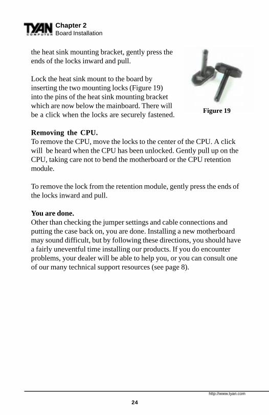
the heat sink mounting bracket, gently press theends of the locks inward and pull.
Lock the heat sink mount to the board byinserting the two mounting locks (Figure 19)into the pins of the heat sink mounting bracketwhich are now below the mainboard. There willbe a click when the locks are securely fastened.
Removing the CPU.To remove the CPU, move the locks to the center of the CPU. A clickwill be heard when the CPU has been unlocked. Gently pull up on theCPU, taking care not to bend the motherboard or the CPU retentionmodule.
To remove the lock from the retention module, gently press the ends ofthe locks inward and pull.
You are done.Other than checking the jumper settings and cable connections andputting the case back on, you are done. Installing a new motherboardmay sound difficult, but by following these directions, you should havea fairly uneventful time installing our products. If you do encounterproblems, your dealer will be able to help you, or you can consult oneof our many technical support resources (see page 8).
Figure 19
Chapter 2Board Installation
http://www.tyan.com
25
Setting Jumpers
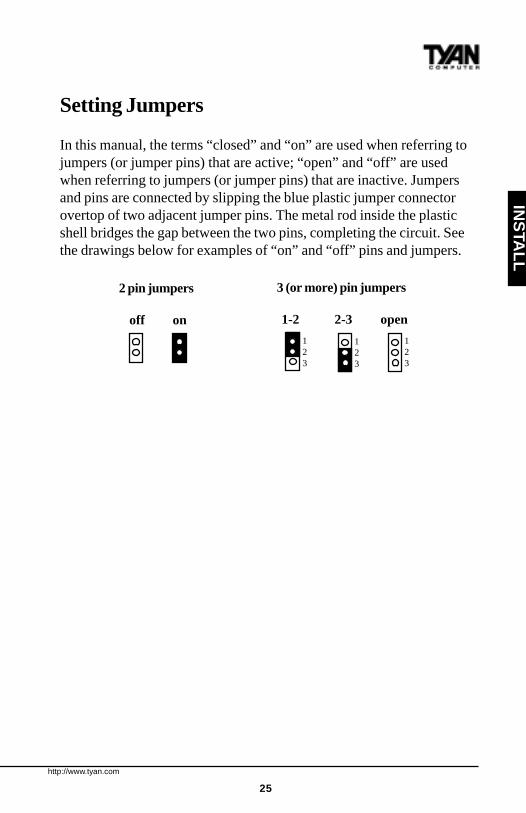
In this manual, the terms “closed” and “on” are used when referring tojumpers (or jumper pins) that are active; “open” and “off” are usedwhen referring to jumpers (or jumper pins) that are inactive. Jumpersand pins are connected by slipping the blue plastic jumper connectorovertop of two adjacent jumper pins. The metal rod inside the plasticshell bridges the gap between the two pins, completing the circuit. Seethe drawings below for examples of “on” and “off” pins and jumpers.
2 pin jumpers
off on
3 (or more) pin jumpers
1-2 2-3 open
123
123
123
INS
TALL

http://www.tyan.com
26
Quick References for Jumpers
The tables on the pages which follow will help you set the jumpers forCPU speed, InfraRed, and external connector pin assignments, amongothers. The miniature motherboard maps will help you locate the jumperson your board. A full-page map of the motherboard can be found on thefacing page.
These jumper settings (manual revision 2.x) correspond to S1832DL re-vision B. Your motherboard should have a large B printed in the corner ofthe board next to the DIMM sockets. If not, please get the correct manualfrom the Tyan web site or contact your dealer.
Chapter 3Onboard Resource Settings
chap
ter 3
Onboard Resource Settings
http://www.tyan.com
27
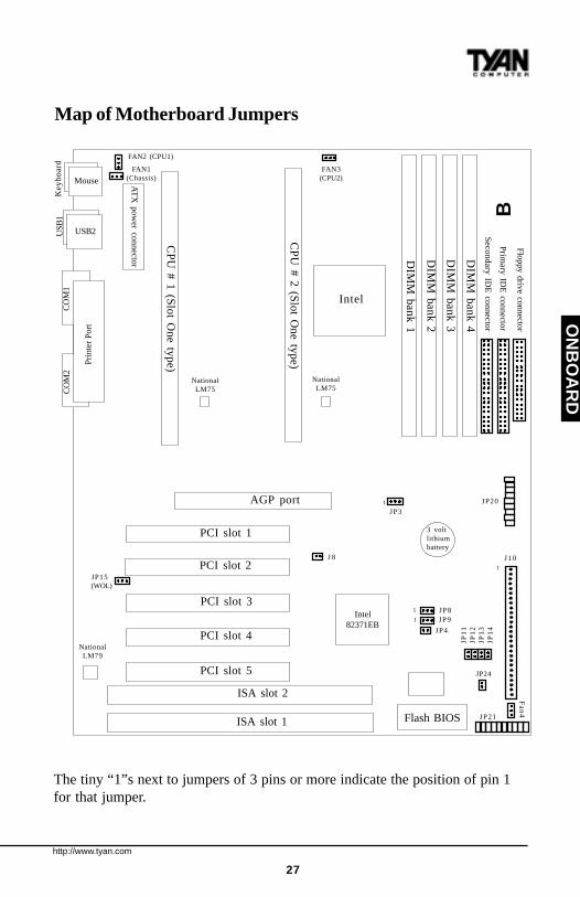
The tiny “1”s next to jumpers of 3 pins or more indicate the position of pin 1for that jumper.
ON
BO
AR
D
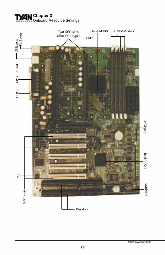
Map of Motherboard Jumpers
US
B1
Ke
ybo
ard
USB2
Mouse
DIM
M b
an
k 3
DIM
M b
an
k 4
3 voltlithiumbattery
CO
M2
CO
M1
Prin
ter
Por
t
PCI slot 2
PCI slot 3
AGP port
PCI slot 4
PCI slot 5
ISA slot 2
ISA slot 1 Flash BIOS
Intel
PCI slot 1
CP
U #
2 (S
lot O
ne
type
)
Intel82371EB
NationalLM75
FAN2 (CPU1)
NationalLM79
DIM
M b
an
k 2
DIM
M b
an
k 1
CP
U #
1 (S
lot O
ne
type
)
1
J10
Floppy drive connector
AT
X p
ow
er co
nn
ecto
r
Se
con
da
ry IDE
con
ne
ctor
Prim
ary ID
E co
nn
ecto
r
FAN1(Chassis)
FAN3(CPU2)
NationalLM75
Fa
n4
JP
11
JP
12
JP
13
JP
14
JP31
JP24
JP21
1 JP8
JP4
1 JP9
J 8
JP15(WOL)
JP20B
http://www.tyan.com
28
Chapter 3Onboard Resource Settings
Intel 443BX
LM75
4 DIMM slots
Intel PIIX
4eA
MIB
IOS
LM
79
2 ISA slots
5 P
CI s
lots
Two SEC slots(Slot One type)
PS
/2 p
orts
US
B p
orts
CO
M2
LPT
1
CO
M1
AG
P port
http://www.tyan.com
29
ON
BO
AR
D
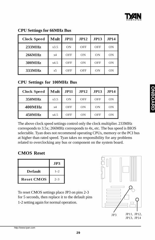
CPU Settings for 66MHz Bus
CPU Settings for 100MHz Bus
The above clock speed settings control only the clock multiplier. 233MHzcorresponds to 3.5x; 266MHz corresponds to 4x, etc. The bus speed is BIOSselectable. Tyan does not recommend operating CPUs, memory or the PCI busat higher than rated speed. Tyan takes no responsibility for any problemsrelated to overclocking any bus or component on the system board.
CMOS Reset
To reset CMOS settings place JP3 on pins 2-3for 5 seconds, then replace it to the default pins1-2 setting again for normal operation.
deepSkcolC tluM 11PJ 21PJ 31PJ 41PJ
zHM332 5.3x NO FFO FFO NO
zHM662 4x FFO NO NO NO
zHM003 5.4x FFO NO FFO NO
zHM333 5x FFO FFO NO NO
deepSkcolC tluM 11PJ 21PJ 31PJ 41PJ
zHM053 5.3x NO FFO FFO NO
zHM004 4x FFO NO NO NO
zHM054 5.4x FFO NO FFO NO
3PJ
tluafeD 2-1
SOMCteseR 3-2
JP11, JP12,JP13, JP14
JP3
http://www.tyan.com
30
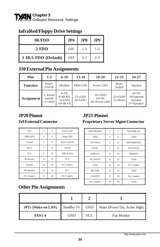
InfraRed/Floppy Drive Settings
J10 External Pin Assignments
JP20 Pinout JP21 Pinout2x9 External Connector Proprietary Server Mgmt Connector
sniP 2-1 01-6 61-31 02-81 32-22 72-42
noitcnuF rewoPffO/nO
deRarfnI DELDDH DELrewoPteseRhctiwS
rekaepS
tnemngissArewoP=1
ffO/nODNG=2
V5=6XRRI=8DNG=9XTRI=01
-DEL=51+DEL=61
DNG=81CN=91
DELrewoP=02
DNG=22teseR=32
V5=42lanretnI=62
rekaepS-rekaepS=72
Chapter 3Onboard Resource Settings
1 2 3
)NALno-ekaW(51PJ V5ybdnatS DNG )hgiHevitcA,nOrewoP(ekaW
4-1NAF DNG CCV rotinoMnaF
DDF/RI 4PJ 8PJ 9PJ
DDF2 NO 2-1 2-1
)tluafeD(DDF1/RI1 FFO 3-2 3-2
CCV 1 2 DELrewoP
DELDDH 3 4 DELpeelS
dnuorG 5 6 ffO/nOrewoP
teseR 7 8 dnuorG
CCV 9 01 hctiwSIMS
evieceRRI 11 21 CCV
dnuorG 31 41 tcennoCoN
timsnarTRI 51 61 CCV
tcennoCoN 71 81 tcennoCoN
#IMSREVRES 1 2 KLCBMSMN
DNG 3 4 DNG
niFFO/NO 5 6 ATADBMSNM
KOPL 7 8 KLNUYEK
TUOIMN 9 01 V3BSMN
#TESR_PF 11 21 DNG
DNG 31 41 tcennoCoN
ERUCES 51 61 DNG
TNISIHC 71 81 tcennoCoN
tcennoCoN 91 02 DNG
Other Pin Assignments

http://www.tyan.com
31
ON
BO
AR
D
Soft Power Connector
The Soft Power Connector is located on pins 1 and 2 of jumper blockJ10. The Tiger 100 uses the PIIX4e chip for power management,including turning on and off the system. If the Power Button Functionoption in the Power Mangement Menu is set to On/Off (which is thedefault), pressing the power button once, after the BIOS has booted up,will turn the system on and off. If the Power Button Function option isset to Suspend, pressing the power button once will wake the system orsend it in to Suspend mode. In this case, you cannot turn the system offunless you shut down through the Windows operating system or youhold the power button down for four seconds.
Speaker Connector Installation
The Tiger 100 provides a 4-pin header to connect the speaker. Thespeaker is connected to pins 24-27 of jumper block J10.
Hardware Reset Switch ConnectorInstallation
The Reset switch on your case’s display panel provides you with theHardware Reset function, which is the same as power on/off. Thesystem will do a cold start after the Reset button is pushed. The Reset
FAN2(CPU1)
FAN3(CPU2)
FAN1(Chassis)
J10
JP4, JP8,JP9
JP15(WOL)
FAN4(Chassis)
http://www.tyan.com
32
Chapter 3Onboard Resource Settings
!important!
switch is a 2-pin connector and should be installed on pins 22 and 23 ofjumper block J10.
Chassis Intrusion Alarm Connector
The J8 connector is an intrusion alarm, that can be connected to thesystem chassis. When active (J8 is closed), this alarm will alert thesystem administrator anytime someone opens the system’s case.
Windows 95 Users:You may encounter problems with some of the devices in the Intel 82371EBchipset. Neither the PCI Bridge nor the PCI Universal Serial Bus deviceIDs for this chipset (also called PIIX4e) are recognized by Windows 95.This is a software problem, not a hardware problem, and can be easilyremedied by either upgrading to Windows 98 or by installing the Win-95Patch found on the Tyan Driver CD and on the Tyan internet and ftpsites: http://www.tyan.com/html/drivers.html or at ftp://download.intel.com/design/pcisets/busmastr/setupex.exe. Note that USB requires Windows95 OSR 2.1 or above; please contact Microsoft for the USB update.
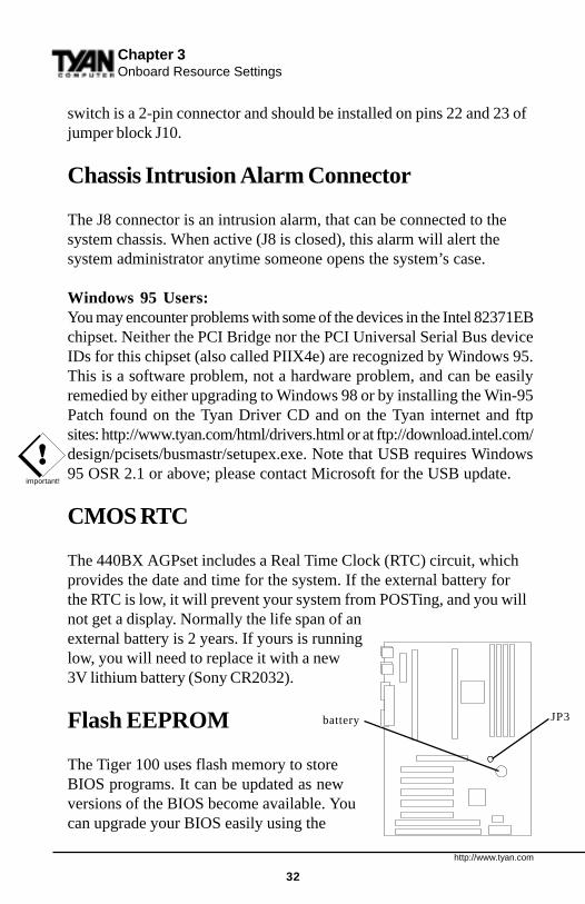
CMOS RTC
The 440BX AGPset includes a Real Time Clock (RTC) circuit, whichprovides the date and time for the system. If the external battery forthe RTC is low, it will prevent your system from POSTing, and you willnot get a display. Normally the life span of anexternal battery is 2 years. If yours is runninglow, you will need to replace it with a new3V lithium battery (Sony CR2032).
Flash EEPROM
The Tiger 100 uses flash memory to storeBIOS programs. It can be updated as newversions of the BIOS become available. Youcan upgrade your BIOS easily using the
battery JP3
http://www.tyan.com
33
procedure
1.2.3.
ON
BO
AR
D
Flash Writer Utility (see page 69).
Hardware CMOS & Password Reset
If you have been locked out of your system because you forgot yourpassword or set the CMOS incorrectly, follow the instructions below.
1. Power off the system2. Set jumper JP3 to pins 2 and 3 (see previous page for location of JP3).3. Wait for 2 seconds, then return jumper JP3 to pins 1 and 2.4. Power on the system again.
By following this procedure, you will erase your password and reset theCMOS to the BIOS defaults.
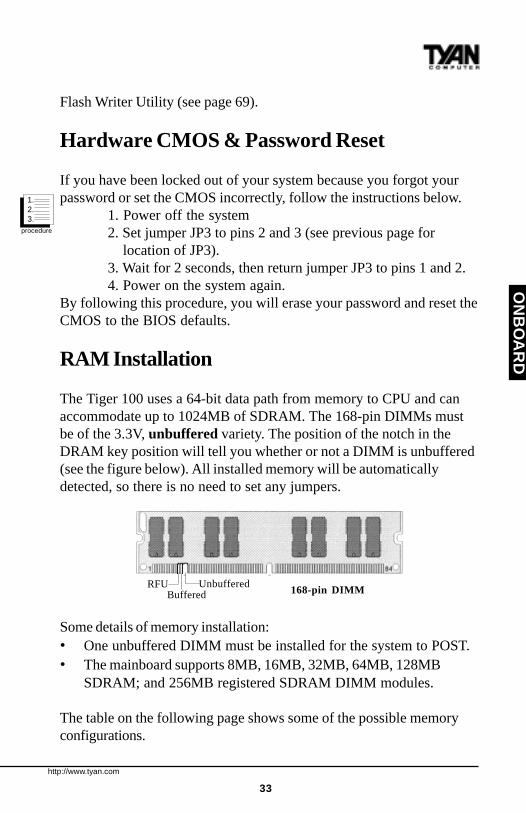
RAM Installation
The Tiger 100 uses a 64-bit data path from memory to CPU and canaccommodate up to 1024MB of SDRAM. The 168-pin DIMMs mustbe of the 3.3V, unbuffered variety. The position of the notch in theDRAM key position will tell you whether or not a DIMM is unbuffered(see the figure below). All installed memory will be automaticallydetected, so there is no need to set any jumpers.
Some details of memory installation:• One unbuffered DIMM must be installed for the system to POST.• The mainboard supports 8MB, 16MB, 32MB, 64MB, 128MB
SDRAM; and 256MB registered SDRAM DIMM modules.
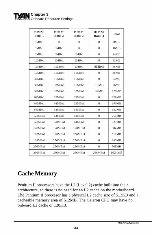
The table on the following page shows some of the possible memoryconfigurations.
RFUBuffered
Unbuffered168-pin DIMM
http://www.tyan.com
34
Cache Memory
Penitum II processors have the L2 (Level 2) cache built into theirarchitecture, so there is no need for an L2 cache on the motherboard.The Pentium II processor has a physical L2 cache size of 512KB and acacheable memory area of 512MB. The Celeron CPU may have noonboard L2 cache or 128KB.
Chapter 3Onboard Resource Settings
MMID1knaB
MMID2knaB
MMID3knaB
MMID4knaB
latoT
1xBM8 0 0 0 BM8
1xBM8 1xBM8 0 0 BM61
1xBM8 1xBM8 1xBM8 0 BM42
1xBM61 1xBM8 1xBM8 0 BM23
1xBM61 1xBM61 1xBM8 1xBM8 BM84
1xBM61 1xBM61 1xBM61 0 BM84
1xBM23 1xBM61 1xBM61 0 BM46
1xBM23 1xBM23 1xBM61 BM61 BM69
1xBM23 1xBM23 1xBM23 BM23 BM821
1xBM46 1xBM23 1xBM23 0 BM821
1xBM46 1xBM46 1xBM23 0 BM061
1xBM46 1xBM46 1xBM46 0 BM291
1xBM821 1xBM46 1xBM46 0 BM652
1xBM821 1xBM821 1xBM46 0 BM023
1xBM821 1xBM821 1xBM821 0 BM483
1xBM821 1xBM821 1xBM652 0 BM215
1xBM821 1xBM652 1xBM652 0 BM046
1xBM652 1xBM652 1xBM652 0 BM867
1xBM652 1xBM652 1xBM652 1xBM652 BM4201
http://www.tyan.com
35
ON
BO
AR
D
Frequently Asked Questions
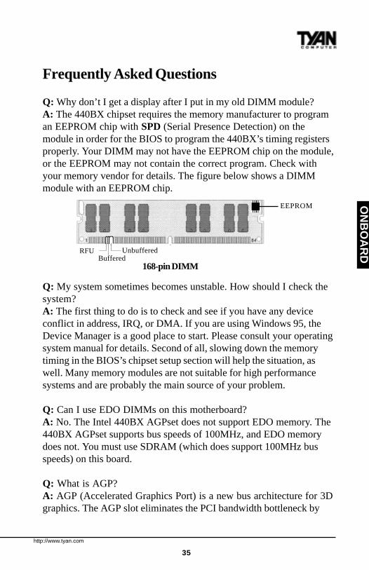
Q: Why don’t I get a display after I put in my old DIMM module?A: The 440BX chipset requires the memory manufacturer to programan EEPROM chip with SPD (Serial Presence Detection) on themodule in order for the BIOS to program the 440BX’s timing registersproperly. Your DIMM may not have the EEPROM chip on the module,or the EEPROM may not contain the correct program. Check withyour memory vendor for details. The figure below shows a DIMMmodule with an EEPROM chip.
Q: My system sometimes becomes unstable. How should I check thesystem?A: The first thing to do is to check and see if you have any deviceconflict in address, IRQ, or DMA. If you are using Windows 95, theDevice Manager is a good place to start. Please consult your operatingsystem manual for details. Second of all, slowing down the memorytiming in the BIOS’s chipset setup section will help the situation, aswell. Many memory modules are not suitable for high performancesystems and are probably the main source of your problem.
Q: Can I use EDO DIMMs on this motherboard?A: No. The Intel 440BX AGPset does not support EDO memory. The440BX AGPset supports bus speeds of 100MHz, and EDO memorydoes not. You must use SDRAM (which does support 100MHz busspeeds) on this board.
Q: What is AGP?A: AGP (Accelerated Graphics Port) is a new bus architecture for 3Dgraphics. The AGP slot eliminates the PCI bandwidth bottleneck by
RFUBuffered
Unbuffered
168-pin DIMM
EEPROM

http://www.tyan.com
36
Chapter 3Onboard Resource Settings
bypassing the PCI interface and accessing the system memory directly.Currently, the AGP supports 1X and 2X modes, which yield bandwidthsof 264MB/s (at 33MHz bus speed) and 533MB/s (at 66MHz busspeed), respectively. Compare this with the mere 132MB/s (at 33MHzbus speed) that you get with the PCI bus.
Q: Does my operating system support AGP?A: Currently, only Windows 98 and Windows NT 5.0 will have built-insupport for AGP. Some AGP cards require Windows 95 OSR2.1 or aspecial driver from Intel. Please check with your graphics vendor formore details.

http://www.tyan.com
37
This page has been intentionally left blank.
http://www.tyan.com
38
Chapter 4BIOS Configuration
chap
ter 4
BIOS Configuration
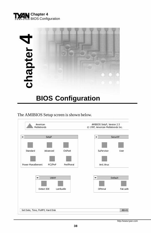
The AMIBIOS Setup screen is shown below.
Setup Security
Standard Advanced Chipset Supervisor User
Power Management PCI/PnP Peripheral Anti-Virus
American AMIBIOS Setup, Version 2.5 Megatrends © 1997, American Megatrends Inc.
Set Date, Time, Floppy, Hard Disk Alt+H:
Utility Default
Detect IDE Language Optimal Fail-safe

http://www.tyan.com
39
BIO
S
You can select a Setup option by manuevering the pointer with yourmouse and clicking the left mouse button, or by using the followingkeyboard keys:
The pages which follow contain explanations of the settings for theAMIBIOS Setup menus. Drawings have been included for ease ofreference, but note that only the first ten lines of any Setup category(e.g. Advanced Setup) are visible in the menu at any time. For example,when you first bring up the Advanced Setup menu, you can only see“Quick Boot” through “Try Other Boot Devices.” In order to see theother options, you must scroll down the menu using either the scroll barat the left hand side, or the arrow keys.
If you are confused, press <Alt> and <H> at the same time to bring upthe help menu. You should not have any trouble, though: the AMIBIOSSetup program is easy to use, and fairly intuitive. Note that the graphicsin the manual are simpler than those that appear on your screen.
yeK noitcnuF
baT .txenehtotxobenomorfsevoM
syekworrA .xobanihtiwnoitcelessegnahC
retnE .noitcelesdethgilhgihsnepO
http://www.tyan.com
40
Chapter 4BIOS Configuration
Standard Setup
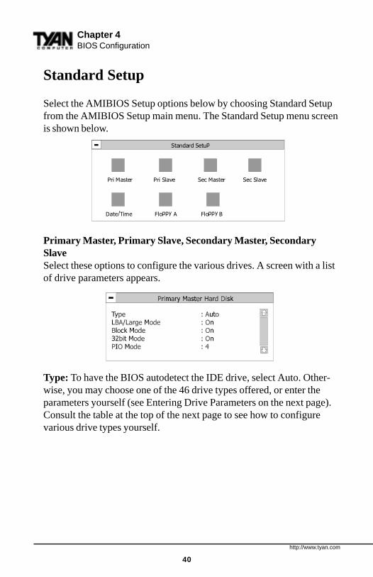
Select the AMIBIOS Setup options below by choosing Standard Setupfrom the AMIBIOS Setup main menu. The Standard Setup menu screenis shown below.
Primary Master, Primary Slave, Secondary Master, SecondarySlaveSelect these options to configure the various drives. A screen with a listof drive parameters appears.
Type: To have the BIOS autodetect the IDE drive, select Auto. Other-wise, you may choose one of the 46 drive types offered, or enter theparameters yourself (see Entering Drive Parameters on the next page).Consult the table at the top of the next page to see how to configurevarious drive types yourself.
Standard Setup
Pri Master Pri Slave Sec Master Sec Slave
Date/Time Floppy A Floppy B
http://www.tyan.com
41
BIO
S
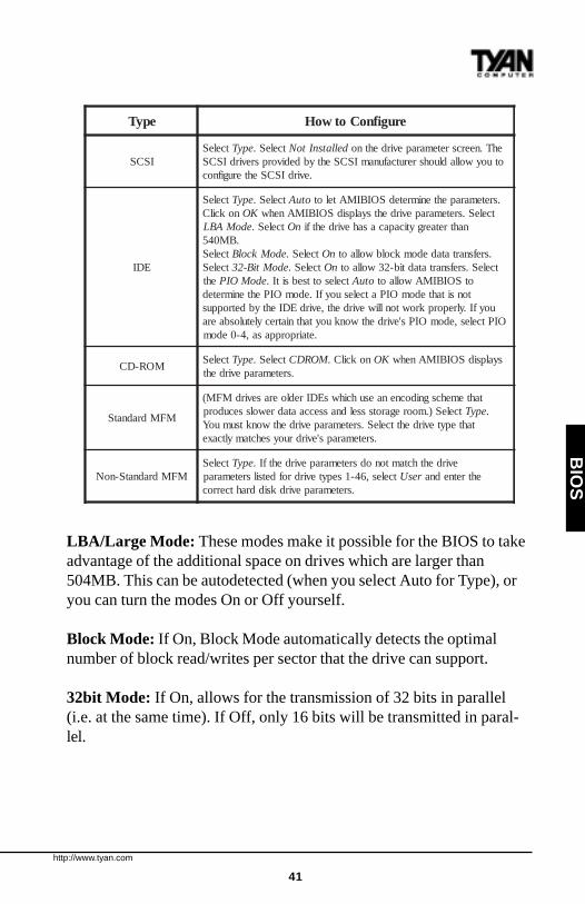
LBA/Large Mode: These modes make it possible for the BIOS to takeadvantage of the additional space on drives which are larger than504MB. This can be autodetected (when you select Auto for Type), oryou can turn the modes On or Off yourself.
Block Mode: If On, Block Mode automatically detects the optimalnumber of block read/writes per sector that the drive can support.
32bit Mode: If On, allows for the transmission of 32 bits in parallel(i.e. at the same time). If Off, only 16 bits will be transmitted in paral-lel.
epyT erugifnoCotwoH
ISCStceleS epyT tceleS. dellatsnItoN ehT.neercsretemarapevirdehtno
otuoywolladluohsrerutcafunamISCSehtybdedivorpsrevirdISCS.evirdISCSehterugifnoc
EDI
tceleS epyT tceleS. otuA .sretemarapehtenimretedSOIBIMAtelotnokcilC KO tceleS.sretemarapevirdehtsyalpsidSOIBIMAnehw
edoMABL tceleS. nO nahtretaergyticapacasahevirdehtfi.BM045
tceleS edoMkcolB tceleS. nO .srefsnartatadedomkcolbwollaottceleS edoMtiB-23 tceleS. nO tceleS.srefsnartatadtib-23wollaot
eht edoMOIP tcelesottsebsitI. otuA otSOIBIMAwollaottonsitahtedomOIPatcelesuoyfI.edomOIPehtenimreted
uoyfI.ylreporpkrowtonlliwevirdeht,evirdEDIehtybdetroppusOIPtceles,edomOIPs'evirdehtwonkuoytahtniatrecyletulosbaera
.etairporppasa,4-0edom
MOR-DCtceleS epyT tceleS. MORDC nokcilC. KO syalpsidSOIBIMAnehw
.sretemarapevirdeht
MFMdradnatS
tahtemehcsgnidocnenaesuhcihwsEDIredloerasevirdMFM(tceleS).mooregarotssseldnasseccaatadrewolssecudorp epyT .
tahtepytevirdehttceleS.sretemarapevirdehtwonktsumuoY.sretemaraps'evirdruoysehctamyltcaxe
MFMdradnatS-noNtceleS epyT evirdehthctamtonodsretemarapevirdehtfI.
tceles,64-1sepytevirdrofdetsilsretemarap resU ehtretnedna.sretemarapevirdksiddrahtcerroc
http://www.tyan.com
42
Chapter 4BIOS Configuration
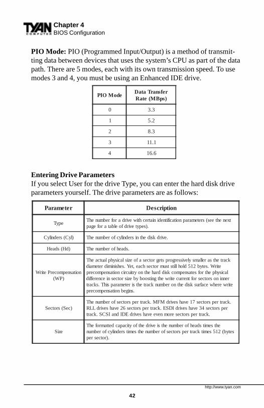
PIO Mode: PIO (Programmed Input/Output) is a method of transmit-ting data between devices that uses the system’s CPU as part of the datapath. There are 5 modes, each with its own transmission speed. To usemodes 3 and 4, you must be using an Enhanced IDE drive.
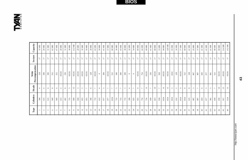
Entering Drive ParametersIf you select User for the drive Type, you can enter the hard disk driveparameters yourself. The drive parameters are as follows:
retemaraP noitpircseD
epyTtxenehtees(sretemarapnoitacifitnediniatrechtiwevirdarofrebmunehT
.)sepytevirdfoelbatarofegap
)lyC(srednilyC .evirdksidehtnisrednilycforebmunehT
)dH(sdaeH .sdaehforebmunehT
noitasnepmocerPetirW)PW(
kcartehtsarellamsylevissergorpstegrotcesafoezislacisyhplautcaehTetirW.setyb215dlohllitstsumrotceshcae,teY.sehsinimidretemaid
lacisyhpehtrofsetasnepmocksiddrahehtnoyrtiucricnoitasnepmocerprenninosrotcesroftnerrucetirwehtgnitsoobybezisrotcesniecnereffid
etirwerehwecafrusksidehtnorebmunkcartehtsiretemarapsihT.skcart.snigebnoitasnepmocerp
)ceS(srotceS.kcartrepsrotces71evahsevirdMFM.kcartrepsrotcesforebmunehT
repsrotces43evahsevirdIDSE.kcartrepsrotces62evahsevirdLLR.kcartrepsrotceseromneveevahsevirdEDIdnaISCS.kcart
eziSehtsemitsdaehforebmunehtsievirdehtfoyticapacdettamrofehT
setyb(215semitkcartrepsrotcesforebmunehtsemitsrednilycforebmun.)rotcesrep
edoMOIPrefsnarTataD)spBM(etaR
0 3.3
1 2.5
2 3.8
3 1.11
4 6.61
http
://w
ww
.tyan
.com
43
BIOS
epyTsrednily
Csdae
Hetir
Wnoitasnep
mocerPsrotceS
yticapaC
1603
48
2171
BM
01
2516
40
0371
BM
02
3516
60
0371
BM
13
4049
82
1571
BM
26
5049
62
1571
BM
74
6516
45
355671
BM
02
7264
86
5271
BM
13
8337
55
355671
BM
03
9009
5153556
71B
M211
01028
35
355671
BM
02
11558
55
355671
BM
53
21558
75
355671
BM
05
31603
88
2171
BM
02
41337
75
355671
BM
34
61216
40
71
BM
02
71779
50
0371
BM
14
81779
75
355671
BM
75
914201
72
1571
BM
06
02337
50
0371
BM
03
12337
70
0371
BM
34
22337
50
0371
BM
03
32603
40
71
BM
01
42529
70
71
BM
45
52529
95
355671
BM
96
62457
74
5771
BM
44
72457
1153556
71B
M96
82996
76
5271
BM
14
92328
0153556
71B
M86
03819
78
1971
BM
35
134201
1153556
71B
M49
234201
5153556
71B
M821
334201
54
20171
BM
34
43216
28
2171
BM
01
534201
95
355671
BM
77
634201
82
1571
BM
86
73516
88
2171
BM
14
83789
37
8971
BM
52
93789
77
8971
BM
75
04028
60
2871
BM
14
14779
57
7971
BM
14
115189
51
8971
BM
14
34038
72
1571
BM
84
44038
0153556
71B
M96
54719
5153556
71B
M411
644221
5153556
71B
M251

http://www.tyan.com
44
Chapter 4BIOS Configuration
Date/TimeYou can type the date and time in directly, or select the portion of thedate or time that you want to modify and adjust it using the plus andminus keys. The plus and minus keys can be activated by clicking onthem with your mouse, or by using the <+> and <-> keys on yourkeyboard. The clock runs on a 24-hour cycle (i.e. 1:00 PM is 13:00).
Floppy Drive A: and B:Move the cursor to these fields via the arrow keys and select the floppytype. The settings are 360KB 5¼ inch, 1.2 MB 5¼ inch, 720KB 3½inch, 1.44MB 3½ inch, or 2.88MB 3½ inch. If you are not sure whattype of floppy drive you have, consult the documentation that came withyour drive.
Date/Time
Date : Tue, Feb 13, 1998
Time : 23:39:23
+
-
http://www.tyan.com
45
BIO
S
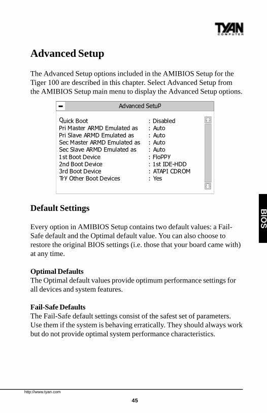
Advanced Setup
The Advanced Setup options included in the AMIBIOS Setup for theTiger 100 are described in this chapter. Select Advanced Setup fromthe AMIBIOS Setup main menu to display the Advanced Setup options.
Default Settings
Every option in AMIBIOS Setup contains two default values: a Fail-Safe default and the Optimal default value. You can also choose torestore the original BIOS settings (i.e. those that your board came with)at any time.
Optimal DefaultsThe Optimal default values provide optimum performance settings forall devices and system features.
Fail-Safe DefaultsThe Fail-Safe default settings consist of the safest set of parameters.Use them if the system is behaving erratically. They should always workbut do not provide optimal system performance characteristics.
Advanced Setup
Quick Boot : DisabledPri Master ARMD Emulated as : Auto
Pri Slave ARMD Emulated as : AutoSec Master ARMD Emulated as : AutoSec Slave ARMD Emulated as : Auto
1st Boot Device : Floppy2nd Boot Device : 1st IDE-HDD3rd Boot Device : ATAPI CDROMTry Other Boot Devices : Yes
Initial Display Mode : BIOS

http://www.tyan.com
46
Chapter 4BIOS Configuration
Advanced Setup
Quick BootSet this option to Enabled to instruct AMIBIOS to boot quickly whenthe computer is powered on. This option replaces the old Above 1 MBMemory Test Advanced Setup option. The settings are:
The Optimal and Fail-safe default settings are Disabled.
Pri/Sec Master/Slave ARMD Emulated asATAPI Removable Media Disks (e.g. ZIP drives) are hybrid drives.They are removable, and can be used as floppy drives, but also havegreat capacity and so are sometimes used as hard drives. These fouroptions ensure that, if you have an ARMD attached as a master or slavedevice, it can be properly detected by the system. The settings are Auto,Floppy, and Hard Disk. The Optimal and Fail-safe default settings areAuto.
1st Boot DeviceThis option sets the type of device for the first boot drive that theAMIBIOS attempts to boot from after AMIBIOS POST completes. Thesettings are Disabled, 1st IDE-HDD, 2nd IDE-HDD, 3rd IDE-HDD,4th IDE-HDD, Floppy, ARMD-FDD, ARMD-HDD, ATAPI CDROM,SCSI, NETWORK, and I
2O. The Optimal and Fail-safe default settings
are Floppy.
gnitteS noitpircseD
delbasiD
.yromemmetsysllastsetSOIBIMA5.rofstiawSOIBIMA.evirdksiddrahEDIehtmorflangisYDAERarofsdnoces04otpustiawSOIBIMA
.niagaydaertegotemitevirdEDIehtwollaotevirdEDIehtotlangisTESERagnidnesretfasdnoces.desserpneebsahyekehtfiputeSSOIBIMAsnurdnasserpyek>leD<arofskcehcSOIBIMA
delbanE
.BM1evobayromemmetsystsettonseodSOIBIMAlangisYDAERafI.evirdksiddrahEDIehtmorflangisYDAERarofsdnoces04otputiawtonseodSOIBIMA
tonseodSOIBIMA.evirdtahterugifnoctonseodSOIBIMA,evirdEDIehtmorfyletaidemmideviecertonsi.niagaydaertegotemitevirdEDIehtwollaotevirdEDIehtotlangisTESERagnidnesretfasdnoces5.roftiaw
ehtrofyaledonsierehtesuaceb,toobmetsystaputeSSOIBIMAnurtonnacuoY puteSnurot>leD<tiH.egassem
http://www.tyan.com
47
2nd Boot DeviceThis option sets the type of device for the second boot drive that theAMIBIOS attempts to boot from after AMIBIOS POST completes. Thesettings are Disabled, 1st IDE-HDD, 2nd IDE-HDD, 3rd IDE-HDD,4th IDE-HDD, Floppy, ARMD-FDD, ARMD-HDD, ATAPI CDROM,and SCSI. The Optimal and Fail-safe default settings are 1st IDE-HDD.
3rd Boot DeviceThis option sets the type of device for the third boot drive that theAMIBIOS attempts to boot from after AMIBIOS POST completes. Thesettings are Disabled, 1st IDE-HDD, 2nd IDE-HDD, 3rd IDE-HDD,4th IDE-HDD, Floppy, ARMD-FDD, ARMD-HDD, ATAPI CDROM.The Optimal and Fail-safe default settings are ATAPI CDROM.
Try Other Boot DevicesSet this option to Yes to instruct AMIBIOS to attempt to boot from anyother drive in the system if it cannot find a boot drive among the drivesspecified in the 1st Boot Device, 2nd Boot Device, and 3rd Boot Deviceoptions. The settings are Yes or No. The Optimal and Fail-safe defaultsettings are Yes.
Floppy Access ControlThis option specifies the read-write access that is set when bootingfrom a floppy drive. The settings are Read-Write or Read-Only. TheOptimal and Fail-safe default settings are Read-Write.
Hard Disk Access ControlThis option specifies the read-write access that is set when bootingfrom a hard disk drive. The settings are Read-Write or Read-Only. TheOptimal and Fail-safe default settings are Read-Write.
S.M.A.R.T. for Hard DisksSet this option to Enabled to permit AMIBIOS to use the SMART(System Management and Reporting Technologies) protocol forreporting server system information over a network. Enabling thisfeature allows you to back up your data when your hard disk is about tofail. The settings are Enabled or Disabled. The Optimal and Fail-safe
BIO
S
http://www.tyan.com
48
Chapter 4BIOS Configuration
default settings are Disabled.
Boot Up Num-LockSet this option to Off to turn the Num Lock key off when the computeris booted so you can use the arrow keys on both the numeric keypadand the keyboard. The settings are On or Off. The default settings areOn.
PS/2 Mouse SupportSet this option to Enabled to enable AMIBIOS support for a PS/2-typemouse. The BIOS will allocate IRQ12 for the PS/2 mouse. Thesettings are Enabled or Disabled. The Optimal and Fail-safe defaultsettings are Enabled.
Primary DisplayThis option configures the type of monitor attached to the computer.The settings are Absent, VGA/EGA, CGA40x25, CGA80x25, orMono. The Optimal and Fail-safe default settings are VGA/EGA.
Password CheckThis option enables password checking every time the system boots orwhen you run AMIBIOS Setup. If Always is chosen, a user passwordprompt appears every time the computer is turned on. If Setup ischosen, the password prompt appears if AMIBIOS is executed. Seethe Advanced Setup chapter for instructions on changing a password.The Optimal and Fail-safe default settings are Setup.
Boot To OS/2Set this option to Yes if you are running an OS/2 operating system andusing more than 64 MB of system memory on the motherboard. Thesettings are Yes or No. The Optimal and Fail-safe default settings areNo.
Internal CacheThis option sets the type of caching algorithm used by the L1 internalcache memory on the CPU. The settings are Disabled, WriteThru, orWriteBack. The Optimal and Fail-safe default settings are WriteBack.

http://www.tyan.com
49
System BIOS CacheableWhen set to Enabled, the contents of the F0000h system memorysegment can be read from or written to cache memory. The contents ofthis memory segment are copied from the BIOS ROM to system RAMfor faster execution. The settings are Enabled or Disabled. The Optimaldefault setting is Enabled. The Fail-safe default setting is Disabled.
Cache Bus ECCWhen Enabled, this option permits ECC error checking on the L2 cachebus. This ensures that cached data is not improperly altered. Thesettings are Enabled or Disabled. The Optimal and Fail-safe defaultsettings are Enabled.
C000,16K Shadow and C400,16K ShadowThese options specify how the 32 KB of video ROM at C0000h istreated. The settings are:
The Optimal and Fail-safe default settings are Cached.
C800,16K Shadow; CC00,16K Shadow; D000,16K Shadow;D400,16K Shadow; D800, 16K Shadow; and DC00,16K ShadowThese options enable shadowing of the contents of the ROM areanamed in the option. The ROM area not used by ISA adapter cards isallocated to PCI adapter cards. The settings are:
BIO
S
gnitteS noitpircseD
delbasiD .MARotdeipoctoneraMORoedivehtfostnetnocehT
delbanEotMORmorf)dewodahs(deipocerahFFF7C-h000CmorfaeraMORoedivehtfostnetnocehT
.noitucexeretsafrofMAR
dehcaCnacdnaMARotMORmorfdeipocerahFFF7C-h000CmorfaeraMORoedivehtfostnetnocehT
.yromemehcacmorfdaerrootnettirweb
gnitteS noitpircseD
delbasiD .MARotdeipoctoneraMORoedivehtfostnetnocehT
delbanEretsafrofMARotMORmorf)dewodahs(deipoceraaeraMORdetangisedehtfostnetnocehT
.noitucexe
dehcaCrootnettirwebnacdnaMARotMORmorfdeipoceraaeraMORdetangisedehtfostnetnocehT
.yromemehcacmorfdaer
The Optimal and Fail-safe default settings are Disabled.

http://www.tyan.com
50
Chipset Setup
Choose Chipset Setup on the AMIBIOS Setup main menu. All ChipsetSetup options are then displayed. AMIBIOS Setup can be customized.AMIBIOS Setup can be customized via AMIBCP. See the AMIBIOSUtilities Guide for additional information.
USB FunctionSet this option to Enabled to enable USB (Universal Serial Bus) sup-port. The settings are Enabled or Disabled. The Optimal and Fail-safedefault settings are Disabled.
USB KB/Mouse Legacy SupportSet this option to Enabled to enable support for older keyboards andmouse devices if the USB Function option is set to Enabled. Thesettings are Enabled or Disabled. The Optimal and Fail-safe defaultsettings are Disabled.
Port 64/60 EmulationSetting this option to Enabled allows a USB keyboard to act like alegacy keyboard. If this option is not Enabled, USB keyboard lights willnot work under Windows NT. With other operating systems, a USBkeyboard will work normally with this option Disabled. The settings areEnabled or Disabled. The Optimal and Fail-safe default settings areDisabled.
Chapter 4BIOS Configuration
http://www.tyan.com
51
BIO
S
SERR#Set this option to Enabled to enable the SERR# signal on the bus. Thesettings are Enabled or Disabled. The Optimal and Fail-safe defaultsettings are Disabled.
PERR#Set this option to Enabled to enable the PERR# signal on the bus. Thesettings are Enabled or Disabled. The Optimal and Fail-safe defaultsettings are Disabled.
WSC# HandshakeSet this option to Enabled to enable handshaking for the WSC# signal.Handshaking is a form of encryption; see the Glossary for more infor-mation. The settings are Enabled or Disabled. The Optimal and Fail-safe default settings are Enabled.
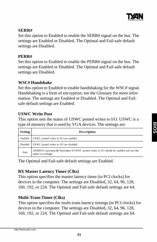
USWC Write PostThis option sets the status of USWC posted writes to I/O. USWC is atype of memory that is used by VGA devices. The settings are:
The Optimal and Fail-safe default settings are Enabled.
BX Master Latency Timer (Clks)This option specifies the master latency timer (in PCI clocks) fordevices in the computer. The settings are Disabled, 32, 64, 96, 128,160, 192, or 224. The Optimal and Fail-safe default settings are 64.
Multi-Trans Timer (Clks)This option specifies the multi-trans latency timings (in PCI clocks) fordevices in the computer. The settings are Disabled, 32, 64, 96, 128,160, 192, or 224. The Optimal and Fail-safe default settings are 64.
gnitteS noitpircseD
delbanE .delbaneeraO/IotsetirwdetsopCWSU
delbasiD .delbasideraO/IotsetirwdetsopCWSU
otuAsihtstesdnadelbaneebdluohsO/IotsetirwdetsopCWSUfisenimretedyllacitamotuaSOIBIMA
.ylgnidroccanoitpo
http://www.tyan.com
52
PCI1 to PCI0 AccessSet this option to Enabled to enable access between two different PCIbuses (PCI1 and PCI0). The settings are Enabled or Disabled. TheOptimal and Fail-safe default settings are Disabled.
Method of Memory DetectionThis option determines how your system will detect the type of systemmemory you have installed. Options are Auto+SPD or Auto only.Optimal and Fail-safe default settings are Auto only.
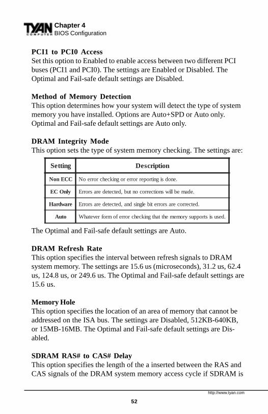
DRAM Integrity ModeThis option sets the type of system memory checking. The settings are:
The Optimal and Fail-safe default settings are Auto.
DRAM Refresh RateThis option specifies the interval between refresh signals to DRAMsystem memory. The settings are 15.6 us (microseconds), 31.2 us, 62.4us, 124.8 us, or 249.6 us. The Optimal and Fail-safe default settings are15.6 us.
Memory HoleThis option specifies the location of an area of memory that cannot beaddressed on the ISA bus. The settings are Disabled, 512KB-640KB,or 15MB-16MB. The Optimal and Fail-safe default settings are Dis-abled.
SDRAM RAS# to CAS# DelayThis option specifies the length of the a inserted between the RAS andCAS signals of the DRAM system memory access cycle if SDRAM is
gnitteS noitpircseD
CCEnoN .enodsignitroperrorrerognikcehcrorreoN
ylnOCE .edameblliwsnoitcerrocontub,detcetederasrorrE
erawdraH .detcerrocerasrorretibelgnisdna,detcetederasrorrE
otuA .desusistroppusyromemehttahtgnikcehcrorrefomrofrevetahW
Chapter 4BIOS Configuration
http://www.tyan.com
53
BIO
S
installed. The settings are Auto, 2 SCLKs or 3 SCLKs. The Optimaldefault setting is Auto. The Fail-Safe default setting is 3 SCLKs.
SDRAM RAS# Precharge(CHANGE) This option specifies the length of the RAS precharge partof the DRAM system memory access cycle when SDRAM systemmemory is installed in this computer. The settings are Auto, 2 SCLKs,or 3 SCLKs. The Optimal default setting is Auto. The Fail-safe defaultsetting is 3 CLKs.
Power Down SDRAMIf this option is set to Enabled, the SDRAM Power Down feature isenabled. The settings are Enabled or Disabled. The Optimal and Fail-safe default settings are Enabled.
ACPI Control RegisterSet this option to Enabled to enable the ACPI (Advanced Configurationand Power Interface) control register. The settings are Enabled orDisabled. The Optimal and Fail-safe default settings are Enabled.
Gated ClockSet this option to Enabled to enable the gated clock. The settings areEnabled or Disabled. The Optimal and Fail-safe default settings areDisabled.
Graphics Aperture SizeThis option specifies the amount of system memory that can be used bythe Accelerated Graphics Port (AGP). The settings are 4 MB, 8 MB,16 MB, 32 MB, 64 MB, 128 MB, or 256 MB. The Optimal and Fail-safe default settings are 64 MB.
Search for MDA ResourcesSet this option to Yes to let AMIBIOS search for MDA resources. Thesettings are Yes or No. The Optimal and Fail-safe default settings areYes.
http://www.tyan.com
54
AGP Mlti-Trans Timer (AGP Clks)This option sets the AGP multi-trans timer. The settings are in units ofAGP Clocks. The settings are Disabled, 32, 64, 96, 128, 160, 192, or224. The Optimal default setting is 16. The Fail-safe default setting isDisabled.
AGP Low-Priority Timer (Clks)This option sets the AGP low priority timer. The settings are in units ofAGP Clocks. The settings are Disabled, 32, 64, 96, 128, 160, 192, or224. The Optimal default setting is 32. The Fail-safe default setting isDisabled.
AGP SERR#Set this option to Enabled to enable the AGP SERR# signal. Thesettings are Enabled or Disabled. The Optimal and Fail-safe defaultsettings are Disabled.
AGP Parity Error ResponseSet this option to Enabled to enable AGP parity error response. Thesettings are Enabled or Disabled. The Optimal and Fail-safe defaultsettings are Disabled.
8bit I/O Recovery TimeThis option specifies the length of a delay inserted between consecutive8-bit I/O operations. The settings are Disabled and from 1 to 8 Sysclk(system clocks) in increments of one. The Optimal and Fail-safedefault settings are Disabled.
16bit I/O Recovery TimeThis option specifies the length of a delay inserted between consecutive16-bit I/O operations. The settings are Disabled and from 1 to 4 Sysclk(system clocks) in increments of one. The Optimal and Fail-safedefault settings are Disabled.
Chapter 4BIOS Configuration
http://www.tyan.com
55
BIO
S
PIIX4 SERR#Set this option to Enabled to enable the SERR# signal for the IntelPIIX4 chip. The settings are Enabled or Disabled. The Optimal andFail-safe default settings are Disabled.
USB Passive ReleaseSet this option to Enabled to enable passive release for USB. Thesettings are Enabled or Disabled. The Optimal and Fail-safe defaultsettings are Enabled.
PIIX4 Passive ReleaseSet this option to Enabled to enable passive release for the Intel PIIX4echip. This option must be Enabled to provide PCI 2.1 compliance. Thesettings are Enabled or Disabled. The Optimal and Fail-safe defaultsettings are Enabled.
PIIX4 DELAYED TRANSACTIONSet this option to Enabled to enable delayed transactions for the IntelPIIX4 chip. This option must be Enabled to provide PCI 2.1 compli-ance. The settings are Enabled or Disabled. The Optimal and Fail-safedefault settings are Enabled.
TypeF DMA Buffer Control1 and 2These options specify the DMA channel where TypeF buffer control isimplemented. The settings are Disabled, Channel-0, Channel-1, Chan-nel-2, Channel-3, Channel-5, Channel-6, or Channel-7. The Optimaland Fail-safe default settings are Disabled.
DMA- n TypeThese options specify the bus that the specified DMA channel can beused on. The settings are Normal ISA, PC/PCI, or Distributed. TheOptimal and Fail-safe default settings are Normal ISA.
http://www.tyan.com
56
Chapter 4BIOS Configuration
Power Management Setup
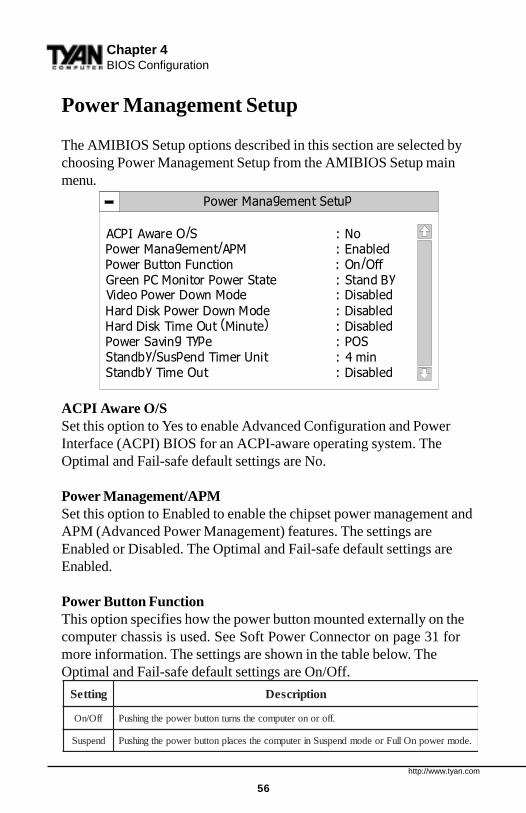
The AMIBIOS Setup options described in this section are selected bychoosing Power Management Setup from the AMIBIOS Setup mainmenu.
ACPI Aware O/SSet this option to Yes to enable Advanced Configuration and PowerInterface (ACPI) BIOS for an ACPI-aware operating system. TheOptimal and Fail-safe default settings are No.
Power Management/APMSet this option to Enabled to enable the chipset power management andAPM (Advanced Power Management) features. The settings areEnabled or Disabled. The Optimal and Fail-safe default settings areEnabled.
Power Button FunctionThis option specifies how the power button mounted externally on thecomputer chassis is used. See Soft Power Connector on page 31 formore information. The settings are shown in the table below. TheOptimal and Fail-safe default settings are On/Off.
gnitteS noitpircseD
ffO/nO .fforonoretupmocehtsnrutnottubrewopehtgnihsuP
dnepsuS .edomrewopnOlluFroedomdnepsuSniretupmocehtsecalpnottubrewopehtgnihsuP
Power Management Setup
ACPI Aware O/S : NoPower Management/APM : EnabledPower Button Function : On/OffGreen PC Monitor Power State : Stand ByVideo Power Down Mode : Disabled
Hard Disk Power Down Mode : DisabledHard Disk Time Out (Minute) : DisabledPower Saving Type : POSStandby/Suspend Timer Unit : 4 minStandby Time Out : Disabled

http://www.tyan.com
57
BIO
S
Green PC Monitor Power StateThis option specifies the power state that the green PC-compliant videomonitor enters when AMIBIOS places it in a power saving state afterthe specified period of display inactivity has expired. The settings areOff, Stand By, or Suspend. The Optimal default setting is Suspend. TheFail-safe default setting is Stand By.
Video Power Down ModeThis option specifies the power state that the video subsystem enterswhen AMIBIOS places it in a power saving state after the specifiedperiod of display inactivity has expired. The settings are Stand By,Suspend, or Disabled. The Optimal default setting is Suspend. The Fail-safe default settings is Disabled.
Hard Disk Power Down ModeThis option specifies the power conserving state that the hard disk driveenters after the specified period of hard drive inactivity has expired. Thesettings are Disabled, Stand By, or Suspend. The Optimal defaultsetting is Suspend. The Fail-safe default settings is Disabled.
Hard Disk Time Out (Minute)This option specifies the length of a period of hard disk drive inactivity.When this length of time expires, the computer enters power-conservingstate specified in the Hard Disk Power Down Mode option (see theprevious page). The settings are Disabled, and from 1 to 15 minutes, inone minute intervals. The Optimal and Fail-safe default settings areDisabled.
Power Saving TypeThere are several types of sleeping states within the general sleepstate. This option allows you to choose how “asleep” you want yoursystem to be. In deeper sleep modes, more energy is saved. However,upon waking up, the system must “reorient” itself, and reestablishcontrol over the system’s sleeping components. The settings are POS,Sleep, Stop Clock, and Deep Sleep. POS is the lightest sleep mode;Deep Sleep is the heaviest. The Optimal and Fail-safe default settingsare POS.
http://www.tyan.com
58
Chapter 4BIOS Configuration
Standby/Suspend Timer UnitThis option specifies the unit of time used for the Standby and Suspendtime out periods. The settings are 4 msec, 4 sec, 32 sec, or 4 min. TheOptimal and Fail-safe default settings are 4 min.
Standby Time OutThis option defines the length of time that the system, while in Full Onstate, must be inactive before it enters Standby mode. The settings areDisabled and from 4 minutes to 508 minutes, in increments of 4 min-utes. The Optimal and Fail-safe default settings are Disabled.
Suspend Time OutThis option defines the length of time that the system, while in Standbymode, must be inactive before it enters Suspend mode.The settings areDisabled and from 4 minutes to to 508 minutes, in increments of 4minutes. The Optimal and Fail-safe default settings are Disabled.
Slow Clock RatioThis option specifies the speed at which the system clock runs in theStandby Mode power saving state. The settings are expressed as apercentage of the normal CPU clock speed. The settings are 0-12.5%,12.5%-25%, 25%-37.5%, 37.5%-50%, 50%-62.5%, 62.5%-75%, or75-87.5%. The Optimal and Fail-safe default settings are 50%-62.5%.
Display ActivityWhen set to Monitor, this option enables event monitoring on the videodisplay. If set to Monitor and the computer is in a power saving state,display activity will cause the system to enter the Full On state.AMIBIOS reloads the Standby and Suspend timeout timers if displayactivity occurs. The settings are Monitor or Ignore. The Optimal andFail-safe default settings are Ignore.
Device n (Device identity)When set to Monitor, these options enable event monitoring on thespecified hardware interrupt request line. If set to Monitor and thecomputer is in a power saving state, any activity on the IRQ line willcause the system to enter the Full On state. AMIBIOS reloads the
http://www.tyan.com
59
BIO
S
Standby and Suspend timeout timers if activity occurs on the specifiedIRQ line. The settings for each of these options are Monitor or Ignore.The Optimal and Fail-safe default settings are Monitor for all devices.
LAN Wake-upWhen this option is Enabled, the system will wake up when a signal isreceived on the Wake-on LAN header. In order for this wake upfunction to work, the system must have been brought up at least pastthe POST before it was last shut down (i.e. if you turn the system offbefore the POST, the registry will not be set, and the system will not beable to wake up using this function). This function requires an ATX2.01 compliant power supply with 5V standby (STB5V) current of atleast 800mA. The settings are Enabled or Disabled. The Optimal andFail-safe default settings are Enabled.
PC98 Power LEDWhen this option is Enabled, your power LED will turn to yellow whenyour system is in Suspend mode. Note that if you do not have a two-color LED, your LED will turn off when the system is in Suspend modeif this option is set to Enabled. The settings are Enabled or Disabled.The Optimal and Fail-safe default settings are Disabled.
FAN OFF at SuspendIf this option is Enabled, the CPU fan will turn off when the system isin Suspend mode. If Disabled, the CPU fan will remain on while thesystem is in Suspend mode. The settings are Enabled or Disabled. TheOptimal and Fail-safe default settings are Enabled.
RTC Wake-upIf Enabled, this option allows you to set an hour and minute for thesystem to wake up. The next two fields allow you to choose the wakeup time. Note that the time fields will not be available if this option isset to Disabled. In order for this wake up function to work, the systemmust have been brought up at least past the POST before it was lastshut down (i.e. if you turn the system off before the POST, the registrywill not be set, and the system will not be able to wake up using thisfunction). The settings are Enabled or Disabled. The Optimal and Fail-safe default settings are Disabled.
http://www.tyan.com
60
Chapter 4BIOS Configuration
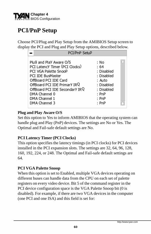
PCI/PnP Setup
Choose PCI/Plug and Play Setup from the AMIBIOS Setup screen todisplay the PCI and Plug and Play Setup options, described below.
Plug and Play Aware O/SSet this option to Yes to inform AMIBIOS that the operating system canhandle plug and Play (PnP) devices. The settings are No or Yes. TheOptimal and Fail-safe default settings are No.
PCI Latency Timer (PCI Clocks)This option specifies the latency timings (in PCI clocks) for PCI devicesinstalled in the PCI expansion slots. The settings are 32, 64, 96, 128,160, 192, 224, or 248. The Optimal and Fail-safe default settings are64.
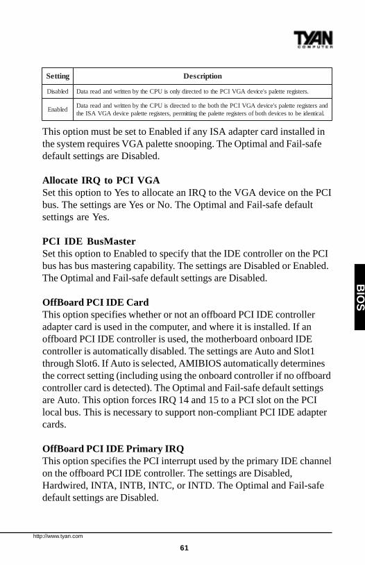
PCI VGA Palette SnoopWhen this option is set to Enabled, multiple VGA devices operating ondifferent buses can handle data from the CPU on each set of paletteregisters on every video device. Bit 5 of the command register in thePCI device configuration space is the VGA Palette Snoop bit (0 isdisabled). For example, if there are two VGA devices in the computer(one PCI and one ISA) and this field is set for:
PCI/PnP Setup
Plug and Play Aware O/S : NoPCI Latency Timer (PCI Clocks) : 64PCI VGA Palette Snoop : Disabled
OffBoard PCI IDE Card : AutoOffBoard PCI IDE Primary IRQ : Disabled
OffBoard PCI IDE Secondary IRQ : DisabledDMA Channel 0 : PnPDMA Channel 1 : PnPDMA Channel 3 : PnP
PCI IDE BusMaster : Disabled
http://www.tyan.com
61
BIO
S
This option must be set to Enabled if any ISA adapter card installed inthe system requires VGA palette snooping. The Optimal and Fail-safedefault settings are Disabled.
Allocate IRQ to PCI VGASet this option to Yes to allocate an IRQ to the VGA device on the PCIbus. The settings are Yes or No. The Optimal and Fail-safe defaultsettings are Yes.
PCI IDE BusMasterSet this option to Enabled to specify that the IDE controller on the PCIbus has bus mastering capability. The settings are Disabled or Enabled.The Optimal and Fail-safe default settings are Disabled.
OffBoard PCI IDE CardThis option specifies whether or not an offboard PCI IDE controlleradapter card is used in the computer, and where it is installed. If anoffboard PCI IDE controller is used, the motherboard onboard IDEcontroller is automatically disabled. The settings are Auto and Slot1through Slot6. If Auto is selected, AMIBIOS automatically determinesthe correct setting (including using the onboard controller if no offboardcontroller card is detected). The Optimal and Fail-safe default settingsare Auto. This option forces IRQ 14 and 15 to a PCI slot on the PCIlocal bus. This is necessary to support non-compliant PCI IDE adaptercards.
OffBoard PCI IDE Primary IRQThis option specifies the PCI interrupt used by the primary IDE channelon the offboard PCI IDE controller. The settings are Disabled,Hardwired, INTA, INTB, INTC, or INTD. The Optimal and Fail-safedefault settings are Disabled.
gnitteS noitpircseD
delbasiD .sretsigerettelaps'ecivedAGVICPehtotdetceridylnosiUPCehtybnettirwdnadaerataD
delbanEdnasretsigerettelaps'ecivedAGVICPehthtobehtotdetceridsiUPCehtybnettirwdnadaerataD.lacitnediebotsecivedhtobfosretsigerettelapehtgnittimrep,sretsigerettelapecivedAGVASIeht
http://www.tyan.com
62
Chapter 4BIOS Configuration
Offboard PCI IDE Secondary IRQThis option specifies the PCI interrupt used by the secondary IDEchannel on the offboard PCI IDE controller. The settings are Disabled,Hardwired, INTA, INTB, INTC, or INTD. The Optimal and Fail-safesettings are Disabled.
PCI Slot n IRQ PriorityThese options specify the IRQ priority for PCI devices installed in thePCI devices installed in the PCI expansion slots. The settings are Auto,IRQ 3, 4, 5, 7, 9, 10, and 11, in priority order. The Optimal and Fail-safedefault settings are Auto.
DMA Channel nThese options allow you to specify the bus type used by each DMAchannel. The settings are PnP or ISA/EISA . The Optimal and Fail-safedefault settings are PnP.
IRQnThese options specify the bus that the specified IRQ line is used on.These options allow you to reserve IRQs for legacy ISA adapter cards.These options determine if AMIBIOS should remove an IRQ from thepool of available IRQs passed to devices that are configurable by thesystem BIOS. The available IRQ pool is determined by reading theESCD NVRAM. If more IRQs must be removed from the pool, you canuse these options to reserve the IRQ by assigning an ISA/EISA settingto it. Onboard I/O is configured by AMIBIOS. All IRQs used byonboard I/O are configured as PCI/PnP. IRQ12 only appears if theMouse Support option in Advanced Setup is set to Disabled. IRQ14 and15 will not be available if the onboard PCI IDE is enabled. If all IRQsare set to ISA/EISA and IRQ14 and 15 are allocated to the onboardPCI IDE, IRQ9 will still be available for PCI and PnP devices, becauseat least one IRQ must be available for PCI and PnP devices. Thesettings are ISA/EISA or PCI/PnP. The Optimal and Fail-safe defaultsettings are PCI/PnP.
http://www.tyan.com
63
BIO
S
Reserved Memory Size This option specifies the size of the memory area reserved for legacyISA adapter cards. The settings are Disabled, 16K, 32K, or 64K. TheOptimal and Fail-safe default settings are Disabled.
Reserved Memory AddressThis option specifies the beginning address (in hex) of the reservedmemory area. The specified ROM memory area is reserved for use bylegacy ISA adapter cards. This option does not appear if the ReservedMemory Size option is set to Disabled. The settings are C0000, C4000,C8000, CC000, D0000, D4000, D8000, or DC000. The Optimal andFail-safe default settings are C8000.
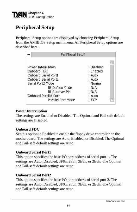
http://www.tyan.com
64
Peripheral Setup
Peripheral Setup options are displayed by choosing Peripheral Setupfrom the AMIBIOS Setup main menu. All Peripheral Setup options aredescribed here.
Power InterruptionThe settings are Enabled or Disabled. The Optimal and Fail-safe defaultsettings are Disabled.
Onboard FDC Set this option to Enabled to enable the floppy drive controller on themotherboard. The settings are Auto, Enabled, or Disabled. The Optimaland Fail-safe default settings are Auto.
Onboard Serial Port1 This option specifies the base I/O port address of serial port 1. Thesettings are Auto, Disabled, 3F8h, 2F8h, 3E8h, or 2E8h. The Optimaland Fail-safe default settings are Auto.
Onboard Serial Port2 This option specifies the base I/O port address of serial port 2. Thesettings are Auto, Disabled, 3F8h, 2F8h, 3E8h, or 2E8h. The Optimaland Fail-safe default settings are Auto.
Peripheral Setup
Power Interruption : DisabledOnboard FDC : EnabledOnboard Serial Port1 : AutoOnboard Serial Port2 : AutoSerial Port2 Mode : Normal
IR Duplex Mode : N/AIR Receiver Pin : N/A
OnBoard Parallel Port : AutoParallel Port Mode : ECP
Chapter 4BIOS Configuration
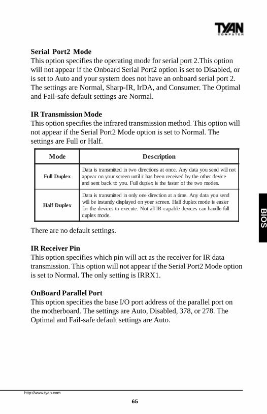
http://www.tyan.com
65
BIO
S
Serial Port2 ModeThis option specifies the operating mode for serial port 2.This optionwill not appear if the Onboard Serial Port2 option is set to Disabled, oris set to Auto and your system does not have an onboard serial port 2.The settings are Normal, Sharp-IR, IrDA, and Consumer. The Optimaland Fail-safe default settings are Normal.
IR Transmission ModeThis option specifies the infrared transmission method. This option willnot appear if the Serial Port2 Mode option is set to Normal. Thesettings are Full or Half.
There are no default settings.
IR Receiver PinThis option specifies which pin will act as the receiver for IR datatransmission. This option will not appear if the Serial Port2 Mode optionis set to Normal. The only setting is IRRX1.
OnBoard Parallel Port This option specifies the base I/O port address of the parallel port onthe motherboard. The settings are Auto, Disabled, 378, or 278. TheOptimal and Fail-safe default settings are Auto.
edoM noitpircseD
xelpuDlluFtonlliwdnesuoyatadynA.ecnotasnoitceridowtnidettimsnartsiataD
ecivedrehtoehtybdeviecerneebsahtilitnuneercsruoynoraeppa.sedomowtehtforetsafehtsixelpudlluF.uoyotkcabtnesdna
xelpuDflaH
dnesuoyatadynA.emitatanoitceridenoylnonidettimsnartsiataDreisaesiedomxelpudflaH.neercsruoynodeyalpsidyltnatsnieblliwllufeldnahnacsecivedelbapac-RIllatoN.etucexeotsecivedehtrof
.edomxelpud

http://www.tyan.com
66
Parallel Port ModeThis option specifies the parallel port mode. The settings are:
The Optimal and Fail-safe default settings are Normal.
EPP VersionThis option specifies the Enhanced Parallel Port specification versionnumber that is used in the system. This option only appears if theParallel Port Mode option is set to EPP. The settings are 1.7 or 1.9.Version 1.9 is common on newer devices; consult your device’s userinformation for the appropriate port type. There are no default settings.
Parallel Port IRQThis option specifies the IRQ used by the parallel port, and onlyappears if OnBoard Parallel Port is set to 278 or 378. The settings are 5or 7. The Optimal and Fail-safe default settings are Auto.
Parallel Port DMA ChannelThis option is only available if the setting for the Parallel Port Modeoption is set to ECP and the OnBoard Parallel Port option is set to 378,278, or 3BC. This option sets the DMA channel used by the parallelport. The settings are 0 through 7 in increments of one. The Optimaland Fail-safe default settings are 3.
Onboard IDEThis option specifies the IDE channel used by the onboard IDE control-ler. The settings are Disabled, Primary, Secondary, or Both. TheOptimal and Fail-safe default settings are Both.
gnitteS noitpircseD
lamroN .desusiedomtroplellaraplamronehT
riD-iB .troplellarapehtnosrefsnartlanoitceridibtroppusotgnittessihtesU
PPEtroPlellaraPdecnahnEehtoterehdatahtsecivedhtiwdesuebnactroplellarapehTcirtemmysaedivorpotslangistroplellarapgnitsixeehtsesuPPE.snoitacificeps)PPE(
.ecivedtsohehtybnevirdrefsnartatadlanoitceridib
PCEtroPseitilibapaCdednetxEehtoterehdatahtsecivedhtiwdesuebnactroplellarapehT
pufosetarrefsnartatadeveihcaotlocotorpAMDehtsesuPCE.snoitacificeps)PCE(.noitacinummoclanoitceridibcirtemmyssedivorpPCE.dnocesrepstibageM5.2ot
Chapter 4BIOS Configuration
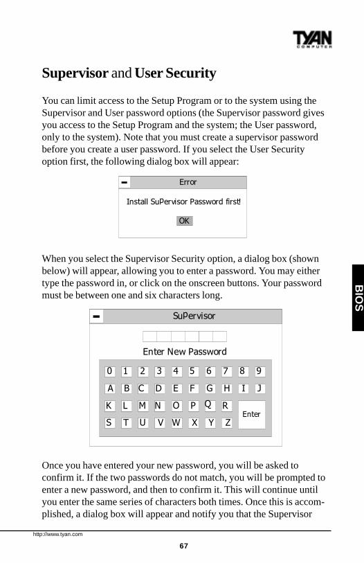
http://www.tyan.com
67
BIO
S
Supervisor and User Security
You can limit access to the Setup Program or to the system using theSupervisor and User password options (the Supervisor password givesyou access to the Setup Program and the system; the User password,only to the system). Note that you must create a supervisor passwordbefore you create a user password. If you select the User Securityoption first, the following dialog box will appear:
When you select the Supervisor Security option, a dialog box (shownbelow) will appear, allowing you to enter a password. You may eithertype the password in, or click on the onscreen buttons. Your passwordmust be between one and six characters long.
Once you have entered your new password, you will be asked toconfirm it. If the two passwords do not match, you will be prompted toenter a new password, and then to confirm it. This will continue untilyou enter the same series of characters both times. Once this is accom-plished, a dialog box will appear and notify you that the Supervisor
Error
Install Supervisor Password first!
OK
Supervisor
Enter New Password
0 1 2 3 4 5 6 7 8 9
A B C D E F G H I J
K L M N O P Q R
S T U V W X Y ZEnter
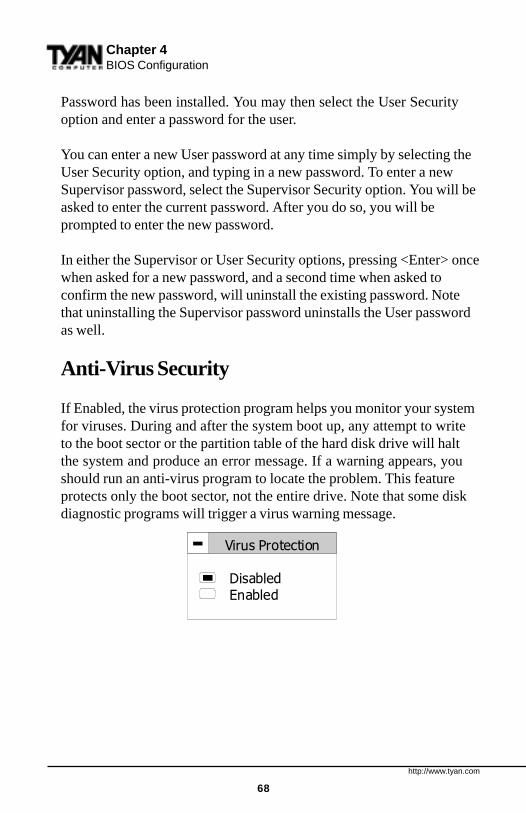
http://www.tyan.com
68
Password has been installed. You may then select the User Securityoption and enter a password for the user.
You can enter a new User password at any time simply by selecting theUser Security option, and typing in a new password. To enter a newSupervisor password, select the Supervisor Security option. You will beasked to enter the current password. After you do so, you will beprompted to enter the new password.
In either the Supervisor or User Security options, pressing <Enter> oncewhen asked for a new password, and a second time when asked toconfirm the new password, will uninstall the existing password. Notethat uninstalling the Supervisor password uninstalls the User passwordas well.
Anti-Virus Security
If Enabled, the virus protection program helps you monitor your systemfor viruses. During and after the system boot up, any attempt to writeto the boot sector or the partition table of the hard disk drive will haltthe system and produce an error message. If a warning appears, youshould run an anti-virus program to locate the problem. This featureprotects only the boot sector, not the entire drive. Note that some diskdiagnostic programs will trigger a virus warning message.
Chapter 4BIOS Configuration
Virus Protection
Disabled
Enabled
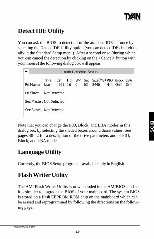
http://www.tyan.com
69
Detect IDE Utility
You can ask the BIOS to detect all of the attached IDEs at once byselecting the Detect IDE Utility option (you can detect IDEs individu-ally in the Standard Setup menu). After a second or so (during whichyou can cancel the detection by clicking on the <Cancel> button withyour mouse) the following dialog box will appear:
Note that you can change the PIO, Block, and LBA modes in thisdialog box by selecting the shaded boxes around those values. Seepages 40-42 for a description of the drive parameters and of PIO,Block, and LBA modes.
Language Utility
Currently, the BIOS Setup program is available only in English.
Flash Writer Utility
The AMI Flash Writer Utility is now included in the AMIBIOS, and soit is simpler to upgrade the BIOS of your mainboard. The system BIOSis stored on a flash EEPROM ROM chip on the mainboard which canbe erased and reprogrammed by following the directions on the follow-ing page.
BIO
S
Auto Detection Status
Type Cyl Hd WP Sec Size(MB) PIO Block LBAPri Master: User 4969 16 0 63 2446 4 On On
Pri Slave: Not Detected
Sec Master: Not Detected
Sec Slave: Not Detected

http://www.tyan.com
70
Chapter 4BIOS Configuration
1. From the DOS prompt, rename the BIOS file that you have down-loaded to “amiboot.rom” and copy it on to a floppy disk.2. Insert the floppy disk with the BIOS upgrade into the A: drive.3. Turn the power off.4. While holding the <Ctrl> and <Home> keys, turn the power on. Thesystem will begin to read from the A: drive, and write the BIOSinformation contained on the floppy disk in that drive to the EEPROMROM chip. When the BIOS has been totally reprogrammed, thesystem will reboot with the new BIOS in operation.5. If the system does not reboot in three minutes, power down the0system, wait a few seconds, and then turn the power back on again.You will be prompted to press <F1> to run Setup. You may check yoursettings at this time, or simply save and exit the program.

http://www.tyan.com
71
BIO
S
This page has been intentionally left blank.
http://www.tyan.com
72
Chapter 6System Resources
chap
ter 5
System Resources
Beep Codes
Fatal errors, which halt the boot process, are communicated through aseries of audible beeps. If AMIBIOS POST can initialize the systemvideo display, it displays the error message. Displayed error messages,in most cases, allow the system to continue to boot. Displayed errormessages are described on pages 74-75. See the top of the next pagefor the beep code chart.

http://www.tyan.com
73
SY
ST
EM
Troubleshooting System Problems
If the computer beeps... then...1, 2, or 3 times... reseat the memory SIMMs or DIPs.
If the system still beeps, replace thememory.
6 times... reseat the keyboard controller chip. Ifit still beeps, replace the keyboardcontroller. If it still beeps, try adifferent keyboard, or replace thekeyboard fuse, if there is one.
8 times... there is a memory error on the videoadapter. Replace the video adapter, orthe RAM on the video adapter.
9 times... the BIOS ROM chip is bad. Thesystem probably needs a new BIOSROM chip.
11 times... reseat the cache memory on themotherboard. If it still beeps, replacethe cache memory.
4, 5, 7, or 10 times... the motherboard must be replaced.
speeB egasseMrorrE noitpircseD
1 eruliaFhserfeR .ytluafsiyrtiucrichserferyromemehT
2 rorrEytiraP .yromemfo)kcolbBK46tsrifeht(yromemesabehtnirorreytiraP
3 eruliaFyromeMBK46esaB .BK46tsrifnieruliafyromeM
4 lanoitarepOtoNremiTtonsi1remiTro,yromemfoBK46tsrifehtnieruliafyromemA
.gninoitcnuf
5 rorrErossecorP .rorrenadetarenegUPCehT
6 eruliaF02AetaG-2408 .edomdetcetorpothctiwstonnaC
7 rorrEtpurretnInoitpecxErossecorP .tpurretninoitpecxenadetarenegdraCUPCehtnoUPCehT
8 rorrEetirW/daeRyromeMyalpsiDsisihT.ytluafsiyromemstirognissimrehtiesiretpadaoedivmetsysehT
.rorrelatafaton
9 rorrEmuskcehCMORnidedocneeulavehthctamtonseodeulavmuskcehcMORehT
.SOIBIMA
01 rorrEetirW/daeRretsigeRnwodtuhSSOMC .deliafsahMARSOMCrofretsigernwodtuhsehT
11 ehcaCelbanEtoNoD—daByromeMehcaCsserptonoD.delbasidsiyromemehcaC.deliaftsetyromemehcacehT
.yromemehcacelbaneot>+<>tfihS<>tlA<>lrtC<
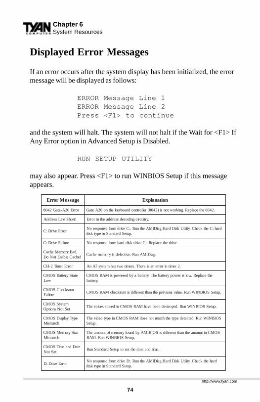
http://www.tyan.com
74
egasseMrorrE noitanalpxE
rorrE02A-etaG2408 .2408ehtecalpeR.gnikrowtonsi)2408(rellortnocdraobyekehtno02AetaG
!trohSeniLsserddA .yrtiucricgnidocedsserddaehtnirorrE
rorrEevirD:Cdrah:CehtkcehC.ytilitUksiDdraHgaiDIMAehtnuR.:CevirdmorfesnopseroN
.puteSdradnatSniepytksid
eruliaFevirD:C .evirdehtecalpeR.:CevirdksiddrahmorfesnopseroN
,daByromeMehcaC!ehcaCelbanEtoNoD
.gaiDIMAnuR.evitcefedsiyromemehcaC
rorrEremiT2-HC .2remitnirorrenasierehT.sremitowtsahmetsysTAnA
etatSyrettaBSOMCwoL
ehtecalpeR.wolsirewopyrettabehT.yrettabaybderewopsiMARSOMC.yrettab
muskcehCSOMCeruliaF
.puteSSOIBNIWnuR.eulavsuoiverpehtnahttnereffidsimuskcehcMARSOMC
metsySSOMCteStoNsnoitpO
.puteSSOIBNIWnuR.deyortsedneebevahMARSOMCniderotsseulavehT
epyTyalpsiDSOMChctamsiM
SOIBNIWnuR.detcetedepytehthctamtonseodMARSOMCniepytoedivehT.puteS
eziSyromeMSOMChctamsiM
SOMCnitnuomaehtnahttnereffidsiSOIBIMAybdnuofyromemfotnuomaehT.puteSSOIBNIWnuR.MAR
etaDdnaemiTSOMCteStoN
.emitdnaetadehttesotputeSdradnatSnuR
rorrEevirD:DdrahehtkcehC.ytilitUksiDdraHgaiDIMAehtnuR.:DevirdmorfesnopseroN
.puteSdradnatSniepytksid
Displayed Error Messages
If an error occurs after the system display has been initialized, the errormessage will be displayed as follows:
ERROR Message Line 1ERROR Message Line 2Press <F1> to continue
and the system will halt. The system will not halt if the Wait for <F1> IfAny Error option in Advanced Setup is Disabled.
RUN SETUP UTILITY
may also appear. Press <F1> to run WINBIOS Setup if this messageappears.
Chapter 6System Resources

http://www.tyan.com
75
egasseMrorrE noitanalpxE
eruliafevird:D .evirdehtecalpeR.:DevirdksiddrahmorfesnopseroN
eruliaFtooBetteksiDesU.metsysehttoobotdesuebtonnac:AevirdnietteksidtoobehT
.snoitcurtsnineercsehtwollofdnaetteksidtoobrehtona
toNhctiwSyalpsiDreporP
rorolocrehtieottesebhctiwsoedivaeriuqersmetsysemoS.norewopneht,ylreporphctiwsehttes,ffometsysehtnruT.emorhconom
rorrEAMD .rellortnocAMDehtnirorrE
rorrE1AMD .lennahcAMDtsrifehtnirorrE
rorrE2AMD .lennahcAMDdnocesehtnirorrE
eruliaFrellortnoCDDF.rellortnocevirdksidyppolfehthtiwetacinummoctonnacSOIBIMA.nwodderewopsimetsysehtretfasnoitcennocetairporppallakcehC
eruliaFrellortnoCDDHkcehC.rellortnocevirdksiddrahehthtiwetacinummoctonnacSOIBIMA
.nwodderewopsimetsysehtretfasnoitcennocetairporppalla
rorrE1RTNI .TSOPdeliaf1lennahctpurretnI
rorrE2RTNI .TSOPdeliaf2lennahctpurretnI
etteksiDtooBdilavnIehttoobtonnactitub,:AevirdyppolfnietteksidehtdaernacSOIBIMA
.snoitcurtsnineercsehtwollofdnaetteksidtoobrehtonaesU.tihtiwmetsys
sIdraobyeKtIkcolnU...dekcoL
ebtsummetsysehT.degagnesimetsysehtnokcoldraobyekehT.tooboteunitnocotdekcolnu
rorrEdraobyeKrellortnoCdraobyeKaerusekaM.melborpgnimitasahdraobyekehT
dellatsnItoNotputeSdecnavdAnidraobyeKteS.dellatsnisiSOIBIMA.senituorTSOPdraobyekehtpiksot
rorrEecafretnI/BK .rotcennocdraobyekehtnirorrenasierehT
CISABMORoNSOIBIMA.:Cro:AevirdrehtienorotceselbatoobreporpadniftonnaC
.cisaBMORdniftonnac
rorrEytiraPdraoBffO
.tolsnoisnapxenanidracretpadananodellatsniyromemnirorreytiraP:sitamrofehT
)XXXX(=RDDARORREYTIRAPDRAOBFFOdnadnifotgaiDIMAnuR.derruccororreehterehwsserddaxehehtsiXXXX
.smelborpyromemtcerroc
rorrEytiraPdraoBnO
:sitamrofehT.yromemdraobrehtomnirorreytiraP)XXXX(=RDDARORREYTIRAPDRAOBNO
dnifotgaiDIMAnuR.derruccororreehterehwsserddaxehehtsiXXXX.smelborpyromemtcerrocdna
????rorrEytiraPotgaiDIMAnuR.sserddanwonknunatayromemmetsysnirorreytiraP
.smelborpyromemtcerrocdnadnif
SY
ST
EM

http://www.tyan.com
76
Chapter 6System Resources
Glossary
ACPI (Advanced Configuration and Power Interface) is a power manage-ment specification that allows the operating system to control the amount ofpower distributed to the computer’s devices. Devices not in use can be turnedoff, reducing unnecessary power expenditure.
AGP (Accelerated Graphics Port) is a PCI-based interface which wasdesigned specifically for demands of 3D graphics applications. The 32-bitAGP channel directly links the graphics controller to the main memory.While the channel runs at only 66MHz, it supports data transmission duringboth the rising and falling ends of the clock cycle, yielding an effective speedof 133MHz.
The AT was the original form factor of IBM’s PC.
ATAPI (AT A ttachment Packet Interface), also known as IDE or ATA, is adrive implementation that includes the disk controller on the device itself. Itallows CD-ROMs and tape drives to be configured as master or slave devices,just like hard drives.
The ATX form factor was designed to replace the AT form factor. It improveson the AT design by rotating the board ninety degrees, so that the IDEconnectors are closer to the drive bays, and the CPU is closer to the powersupply and cooling fan. The keyboard, mouse, serial, USB, and parallel portsare built in.
Bandwidth refers to carrying capacity. The greater the bandwidth, themore data the bus, phone line, or other electrical path, can carry. Greaterbandwidth, then, also results in greater speed.
A BBS (Bulletin Board System) is a computer system with a number ofmodems hooked up to it which acts as a center for users to post messages andaccess information.
The BIOS (Basic Input/Output System) program resides in the ROM chip,and provides the basic instructions for controlling your computer’s hardware.
http://www.tyan.com
77
Both the operating system and application software use BIOS routines toensure compatibility.
A buffer is a portion of RAM which is used to temporarily store data, usuallyfrom an application, though it is also used when printing, and in most key-board drivers. The CPU can manipulate data in a buffer before copying it, all atonce, to a disk drive. While this improves system performance--reading to orwriting from a disk drive a single time is much faster than doing so repeatedly--there is the possibility of losing your data should the system crash. Informa-tion stored in a buffer is temporarily stored, not permanently saved.
A bus is a data pathway. The term is used especially to refer to the connec-tion between the processor and system memory, and between the processorand PCI or ISA local buses.
Bus mastering allows peripheral devices and IDEs to access the systemmemory without going through the CPU (similar to DMA channels).
A cache is a temporary storage area for data that will be needed often by anapplication. Using a cache lowers data access times, since the neededinformation is stored in the SRAM instead of in the slower DRAM. Note thatthe cache is also much smaller than your regular memory: a typical cachesize is 512KB, while you may have as much as 1GB of regular memory.
Cache size refers to the physical size of the cache onboard. This should notbe confused with the cacheable area, which is the total amount of memorywhich can be scanned by the system in search of data to put into the cache. Atypical setup would be a cache size of 512KB, and a cacheable area of512MB. In this case, up to 512MB of the main memory onboard is capable ofbeing cached. However, only 512KB of this memory will be in the cache atany given moment. Any main memory above 512MB could never be cached.
Closed and open jumpers Jumpers and jumper pins are active whenthey are On or Closed, and inactive when they are Off or Open.
CMOS Complementary Metal-Oxide Semiconductors are chips that holdthe basic start-up information for the BIOS.
SY
ST
EM
http://www.tyan.com
78
The COM port is another name for the serial port, which is so-calledbecause it transmits the eight bits of a byte of data along one wire, andreceives data on another single wire (that is, the data is transmitted in serialform, one bit after another). Parallel ports transmit the bits of a byte on eightdifferent wires at the same time (that is, in parallel form, eight bits at the sametime).
DIMM Dual In-line Memory Modules are a faster and more capaciousform of RAM than SIMMs, and do not need to be installed in pairs.
DIMM bank DIMM banks are sometimes called DIMM sockets, becausethe physical slot and the logical unit are the same. That is, one DIMMmodule fits into one DIMM socket, which is capable of acting as a memorybank.
DMA Direct Memory Access channels are similar to IRQs. DMA channelsallow hardware devices (like sound cards or keyboards) to access the mainmemory without involving the CPU. This frees up CPU resources for othertasks. As with IRQs, it is vital that you do not double up devices on a singleline. Plug and Play devices will take care of this for you.
In Doze mode, only the CPU’s speed is slowed.
DRAM Dynamic RAM is a widely available, very affordable form of RAMwhich has the unfortunate tendency to lose data if it is not recharged regu-larly (every few milliseconds). This refresh requirement makes DRAMslower three to ten times slower than non-recharged RAM such as SRAM.
EDO RAM (Extended Data-Out RAM ) speeds access to memory loca-tions by assuming that memory addresses are static: the next time it looks fora bit of data, it will be at the same spot, or one nearby.
EEPROM Electrically Erasable Programmable ROM, also called FlashBIOS, is a ROM chip which can, unlike normal ROM, be updated. Thisallows you to keep up with changes in the BIOS programs without having tobuy a new chip. TYAN’s BIOS updates can be found at http://www.tyan.com/html/drivers.html
Chapter 6System Resources
http://www.tyan.com
79
ESCD (Extended System Configuration Data) is a format for storing informa-tion about Plug and Play devices in the system BIOS. This information helpsproperly configure the system each time it boots.
Firmware is low level software that controls the system hardware.
Form factor is an industry term for the size, shape, power supply type,and external connector type of the PCB (personal computer board) ormotherboard. The standard form factors are the AT and ATX, althoughTYAN also makes some Baby-AT boards.
A Global timer is an onboard hardware timer, such as the Real TimeClock.
Handshaking is a form of encryption. One system, typically the server,sends an encryption scheme to another agent, typically a client. Thus, theclient’s data is protected during transmittal to the server.
HDD stands for Hard Disk Drive.
H-SYNC controls the horizontal properties of the monitor.
IC (Integrated Circuit) is the formal name for the computer chip.
IDE Integrated Device (or Drive) Electronics is a simple, self-containedhard drive interface. It can handle drives up to 8.4GB in size. Almost allIDEs sold now are in fact Enhanced IDEs (EIDEs).
IDE INT (IDE Int errupt) is a hardware interrupt signal that goes to theIDE.
I/O Input/Output is the connection between your computer and anotherpiece of hardware (mouse, keyboard, etc.).
IRQ An Interrupt Request is an electronic request that runs from a hard-ware device to the CPU. The interrupt controller assigns priorities to incom-ing requests and delivers them to the CPU. It is important that there is onlyone device hooked up to each IRQ line; doubling up devices on IRQ lines can
SY
ST
EM
http://www.tyan.com
80
lock up your system. Happily, Plug and Play operating systems take care ofthese details for you.
ISA stands for Industry Standard Architecture. ISA is a slower 8- or 16-bitBUS (data pathway).
Latency is the amount of time that one part of a system spends waiting foranother part to catch up. This is most common when the system sends dataout to a peripheral device, and is waiting for the peripheral to send some databack (peripherals tend to be slower than onboard system components).
NVRAM ROM and EEPROM are both examples of Non-Volatile RAM ,memory that holds its data without power. DRAM, in contrast, is volatile.
OEMs (Original Equipment Manufacturers) like Compaq or IBM packageother companies’ motherboards and hardware inside their case and sell them.
The parallel port transmits the bits of a byte on eight different wires at the
same time (that is, in parallel form, eight bits at the same time).
PCI stands for Peripheral Component Interconnect. PCI is a 32-bit local bus(data pathway) which is faster than the ISA bus. Local buses are those whichoperate within a single system (as opposed to a network bus, which connectsmultiple systems).
The PCI PIO (PCI Programmable Input/Output) modes are the datatransfer modes used by IDE drives. These modes use the CPU for datatransfer (DMA channels do not). PCI refers to the type of bus used by thesemodes to communicate with the CPU.
PCI-to-PCI bridge allows you to connect multiple PCI devices onto one
PCI slot.
Pipeline burst SRAM is a fast secondary cache. It is used as a secondarycache because SRAM is slower than SDRAM, but usually larger. Data iscached first to the faster primary cache, and then, when the primary cache isfull, to the slower secondary cache.
Chapter 6System Resources
http://www.tyan.com
81
Pipelining improves system performance by allowing the CPU to beginexecuting a second instruction before the first is completed. A pipeline can belikened to an assembly line, with a given part of the pipeline repeatedlyexecuting a set part of an operation on a series of instructions.
PM timers (Power Management timers) are software timers that countdown the number of seconds or minutes until the system times out and enterssleep, suspend, or doze mode.
PnP is an acronym for Plug and Play, a design standard that has becomeascendant in the industry. Plug and Play devices require little set-up to use.Novice end users can simply plug them into a computer that is running on aPlug and Play-aware operating system (such as Windows 95), and go towork. Devices and operating systems that are not Plug and Play require youto reconfigure your system each time you add or change any part of yourhardware.
The term RAM (Random Access Memory), while technically referring to atype of memory where any byte can be accessed without touching theadjacent data, is often used to refer to the system’s main memory. Thismemory is available to any program running on the computer.
ROM (Read-Only Memory) is a storage chip which contains the BIOS(Basic Input/Output System), the basic instructions required to boot thecomputer and start up the operating system.
SDRAM (Synchronous Dynamic RAM ) is so-called because it can keeptwo sets of memory addresses open simultaneously. By transferring dataalternately from one set of addresses, and then the other, SDRAM cuts downon the delays associated with non-synchronous RAM, which must close oneaddress bank before opening the next.
The serial port is so called because it transmits the eight bits of a byte ofdata along one wire, and receives data on another single wire (that is, thedata is transmitted in serial form, one bit after another).
SIMM Single In-line Memory Modules are the most common form of RAM.They must be installed in pairs, and do not have the carrying capacity or thespeed of DIMMs.
SY
ST
EM

http://www.tyan.com
82
SIMM bank/socket SIMM sockets are the physical slots into which youstick SIMM modules. A pair of SIMM sockets form a SIMM bank, and act asa unit. If only one socket is filled, the bank will not operate.
In Sleep/Suspend mode, all devices except the CPU shut down.
SRAM Static RAM , unlike DRAM, does not need to be refreshed in orderto prevent data loss. Thus, it is faster, and more expensive.
In Standby mode, the video and fixed disk drive shut down; all otherdevices operate normally.
UltraDMA/33 is a fast version of the old DMA channel. UltraDMA isalso called UltraATA. Without UltraDMA your system cannot take advantageof the higher data transmission rates of the new UltraATA hard drives.
Universal Serial Bus or USB, is a versatile port. This one port type canfunction as a serial, parallel, mouse, keyboard, or joystick port. It is fastenough to support video transfer, and is capable of supporting up to 127daisy-chained peripheral devices.
VGA (Video Graphics Array) is the PC video display standard.
V-SYNC controls the vertical properties of the monitor.
ZIF socket Zero Insertion Force sockets make it possible to insert CPUswithout damaging the sensitive pins. The CPU is lightly placed in an openZIF socket, and the metal lever pulled down. This shifts the processor overand down, guiding it into place on the board.
Chapter 6System Resources

http://www.tyan.com
83
Notice for the USACompliance Information Statement (Declaration of Conformity Proce-dure) DoCFCC Part 15: This Device complies with Part 15 of the FCC Rules.Operation is subject to the following conditions:1) this device may not cause harmful interference, and2) this device must accept any interference received including interfer-ence that may cause undesired operation. If this equipment does causeharmful interference to radio or television reception, which can bedetermined by turning the equipment off and on, the user is encouragedto try one or more of the following measures:
· Reorient or relocate the receiving antenna.· Increase the separation between the equipment and receiver.· Plug the equipment into an outlet on a circuit different from
that of the receiver.· Consult the dealer or an experienced radio/television
technician for help.
CAUTION : LITHIUM BATTERIES included with This PC board.Danger of explosion if battery is incorrectly replaced. Replace ONLYwith the same or equivalent type recommended by manufacturer.Dispose of used batteries according to manufacturer instructions.
Notice for CanadaThis apparatus complies with the Class B limits for radio interferenceas specified in the Canadian Department of Communications RadioInterference Regulations.
Cet appareil est conforme aux normes de Classe B d’ interferenceradio tel que spécifié par le Ministére Canadien des Communicationsdans les réglements d’interférence radio.
Notice for Europe (CE Mark)This product is in conformity with the Council Directive 89/336/EEC,92/31/EEC (EMC).
Document # D1308-020
SY
ST
EM