wintex user guide - texecom ltd1...commissioning an account.....25 engineer database .....25...
TRANSCRIPT

MAINTEX™
User Guide
INS571

MAINTEX™ User Guide
ContentsContents .................................................................... 2 Introduction .............................................................. 3
Installation .................................................................. 3 Starting Maintex ......................................................... 3
User Logon ................................................................ 4 How to create a new Operator ................................... 5
Connection Setup ..................................................... 7 Modem Setup.............................................................. 8 Network Setup .......................................................... 10 Serial/ USB Setup ..................................................... 10 Time Slots ................................................................. 11 General ...................................................................... 11
Account Setup ........................................................ 13 Account icon status.................................................. 19 Accounts Overview .................................................. 20
Maintenance Schedule & History ......................... 21 ALL ............................................................................ 21 Completed................................................................. 22 Scheduled ................................................................. 22 History ....................................................................... 23
Remote Monitoring ................................................ 24 Commissioning an account ................................... 25
Engineer Database ................................................... 25 Commissioning from the PC ................................... 25 Commissioning from site ......................................... 26
Debug View ............................................................. 27

MAINTEX™ User Guide
INS571 3
Introduction Maintex is a user friendly Windows based software, designed for use with the Premier24/48/88/168 (all firmware versions are supported) and all Premier Elite 12/24/48/88/168 & 640 control panels, and provides a means of remote servicing for Texecom intrusion systems.
The Premier 640 is NOT supported by Maintex.
Remote Maintenance can be achieved via;
• IP connections using a Texecom Com-IP module/ Emizon unit/ Web-Way one and GPRS (using our Elite com GSM)
a fixed IP SIM card is required to achieve this • PSTN connections using USB/Serial modems, such as the Texecom USB Modem
the Control panel modem MUST be a COM2400 for calls initiated from the panel. Panels fitted with a COM300 may be used, however the call MUST be initiated from the PC, meaning that the call charges will be with the installer and NOT the end user. Using a COM300, because of its lower baud rate WILL result in lengthy calls and may incur significant telephone call costs.
• Direct local connections via USB/ Serial leads.
Maintex software allows you to set maintenance dates and times, and allows individual site parameters for all of the testing options. These include voltages, system current and any active faults.
Installation Maintex will function on any Windows™ based PC with an operating system that is XP/Vista/ 7/ 8. 32 Bit and 64Bit systems are supported.
Maintex can be downloaded from the Texecom website providing you are a Registered Installer. Please visit http://www.texe.com to register.
Maintex will be installed in C:\Program Files\Texecom where C: is the designated hard drive. In the case of 64 bit systems, the program will be installed in C:\Program Files (x86)\Texecom.
Wintex is also required to allow importing of account information, a common database ensures both programs information are always up to date.
Once installation is complete you can use Maintex for the first time.
Starting Maintex To open the program click on the icon created during setup, if you chose not to create an Icon the application can be started from the program list under the Texecom folder.
The following window will appear;

MAINTEX™ User Guide
User Logon You can log in by selecting the ‘Login’ icon or by selecting ‘Operator’ – ‘Login’;
Once you have selected one of the mentioned methods of Login the following window will appear;
Default Username = Master
Default Password = 123456
Once you have successfully logged into Maintex your screen will be populated with all the Maintex options and operations;

MAINTEX™ User Guide
INS571 5
How to create a new Operator Although it is not essential to the operation of Maintex to have individual operators it is strongly recommended that you assign individual user names and passwords for any person who will use the program. An audit trail of activity is required by PD6662 and DD263.
Select from the top toolbar ‘Operator’ and ‘Operator Db’ (Operator Database)
the below window will open;
1. This is where all created operators will appear
2. These are the individual rights assigned to the operator
3. Selecting this icon will allow the addition of a new operator
4. Selecting this Icon will delete the selected operator
5. Selecting this Icon will edit the current highlighted operator
6. This will close the current window
MAINTEX™ User Guide
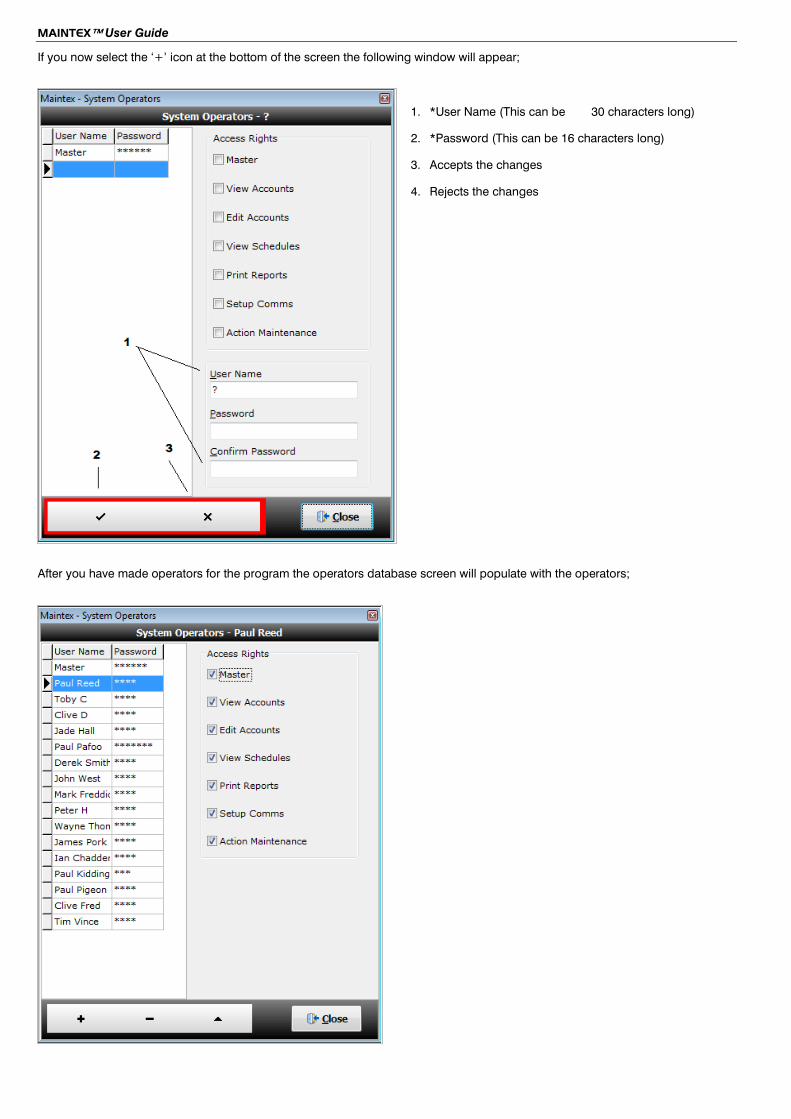
If you now select the ‘+’ icon at the bottom of the screen the following window will appear;
1. *User Name (This can be 30 characters long)
2. *Password (This can be 16 characters long)
3. Accepts the changes
4. Rejects the changes
After you have made operators for the program the operators database screen will populate with the operators;

MAINTEX™ User Guide
INS571 7
Connection Setup To achieve remote maintenance you will need to ensure you have Maintex configured correctly for the connection type.
To gain access to the setup menu you will need to ensure that your user login has access to the ‘Setup Comms’ menu (see previous pages) you can select the ‘setup’ icon, or from the top tool bar select ‘Comms’ > ‘Setup’.
The following window will appear;
There are 5 tabs to select from;
• Modem • Network • Serial/USB • Time Slots • General

MAINTEX™ User Guide
Modem Setup
Communication Port Select the Com Port that the modem is connected to. This can be set to Com1 - Com 64 (this will be the comport number of your USB on your PC, this can be obtained from device manager on your PC when the modem is connected and powered)
Baud Rate Select the Baud Rate that the modem will use.
Modem Name Select the Modem type from the drop down selection box.
When you select a modem the Configuration String for the modem is also loaded and displayed in the Configuration String edit box. If required the modem may be edited by clicking on the ‘Edit Modem button’. This will display all configuration information for the selected modem:

MAINTEX™ User Guide
INS571 9
Modem Edit screen information – Commands Name The Name of the selected modem. ( This cannot be changed through Maintex)
Initialize The command used to reset the modem, normally ATZ^M.
Dial The command used to dial, normally ATD.
Dial suffix The command used to initiate the dialling sequence, normally ^M.
Cancel Dial The command used to cancel a dialling attempt, normally ^M.
Hang-up The command used to hang up the modem, normally ~~~+++~~~ATH0^M.
Answer The command used to answer an incoming call, normally ~ATA^M.
Configure The custom configuration string; see Modem Configuration String Guidelines below
V21 The parameter for 300 baud speed used by the panel, normally S37=3
V22bis The parameter for 2400 baud speed used by the panel, normally S37=6
Return Codes Okay The modem response to a valid command, normally OK.
Connect The modem response when connected with another modem, normally CONNECT.
Busy The modem response when a busy line is detected, normally BUSY.
Voice The modem response when a voice response is detected, normally VOICE.
No Carrier The modem response when a carrier could not be detected, normally NO CARRIER.
No Dial tone The modem response when a no dial tone is detected, normally NO DIALTONE.
Error The modem response to an invalid command, normally ERROR.
Ring The modem response when ringing is detected, normally RING.
If you are unsure about any of these command strings you will need to contact the manufacture of your modem.

MAINTEX™ User Guide
Network Setup
Under the Network tab – you have the above options available to edit – under normal circumstances you should not need to edit these settings; however it is advised to check with the host of the network to ensure these settings are correct.
Serial/ USB Setup
When using a PC com (Serial 9 pin lead)/ USB com or Radio Pad you must ensure you have set the correct port number to be used for Maintex.
Using the provided dropdown boxes you can set which comport is being used – for each individual means of connection.
this is not the Com-Port of the control panel, this is the comport being used by the PC.

MAINTEX™ User Guide
INS571 11
Time Slots
Under the Time slots tab you can specify the time frames in which you wish for the remote maintenance to initialise.
Maintex already has pre defined time windows; however you can create your own time windows by adding a Schedule Name/ Start Time and End Time.
this has to be set in a 24 hour clock period.
General
MAINTEX™ User Guide
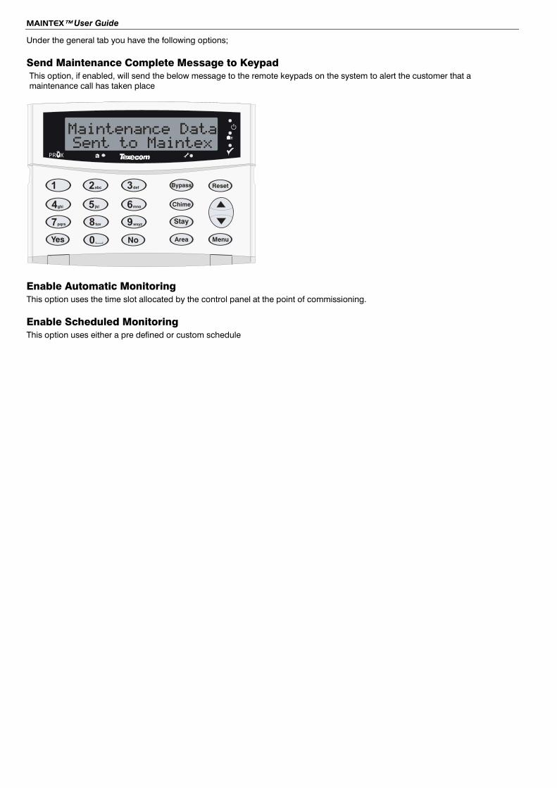
Under the general tab you have the following options;
Send Maintenance Complete Message to Keypad This option, if enabled, will send the below message to the remote keypads on the system to alert the customer that a maintenance call has taken place
b
eF
1 2 3
4 5 6
7 8 9
0y n
B
C
s
A
R
N
PMaintenance Data
PR XSent to Maintex
Enable Automatic Monitoring This option uses the time slot allocated by the control panel at the point of commissioning.
Enable Scheduled Monitoring This option uses either a pre defined or custom schedule

MAINTEX™ User Guide
INS571 13
Account Setup To add a new account you will need to ensure that your operator login has access to add/edit accounts.
From the main screen select the ‘+’ icon at the bottom of the screen;
This will now direct you to the accounts details screen;
Each new installation to be included in the remote maintenance schedule will require a Maintex account.
To create a new account in Maintex You will need to import your Wintex profile, using the import account icon located at the bottom of the form, the relevant panel information from the customer file will then populate the fields;

MAINTEX™ User Guide
if Maintex does not automatically locate your Wintex customer files you will need to view in Wintex where your customer files are being stored – Please see our Wintex user guide INS549 by pressing the help button in Wintex for information.

MAINTEX™ User Guide
INS571 15
As can be seen in the above example Maintex gathers all panel information from the Wintex file – These details can be edited from Maintex if required which will update the Wintex profile also.
Once your profile has been correctly imported into Maintex select the ‘Tick’ icon on the bottom of the form. This will save the configuration for the profile – and will now allow you database control on the bottom tray to Add/Edit and View other Maintex accounts;
1 – These controls allow the operator to;
• Go to the first saved Maintex account • Step back an account • Step forward an account • Go to the last saved Maintex account • Add a new Maintex account • Disable a Maintex account • Edit a Maintex account
2 – The operator can search for a specific user account by a means of different search options listed in the above screen capture.
MAINTEX™ User Guide
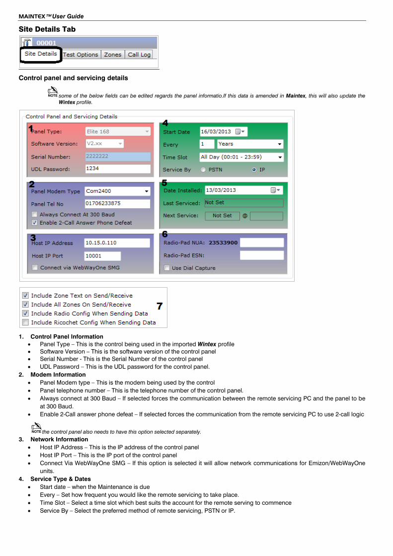
Site Details Tab
Control panel and servicing details
some of the below fields can be edited regards the panel informatio.If this data is amended in Maintex, this will also update the Wintex profile.
1. Control Panel Information • Panel Type – This is the control being used in the imported Wintex profile • Software Version – This is the software version of the control panel • Serial Number - This is the Serial Number of the control panel • UDL Password – This is the UDL password for the control panel.
2. Modem Information • Panel Modem type – This is the modem being used by the control • Panel telephone number – This is the telephone number of the control panel. • Always connect at 300 Baud – If selected forces the communication between the remote servicing PC and the panel to be
at 300 Baud. • Enable 2-Call answer phone defeat – If selected forces the communication from the remote servicing PC to use 2-call logic
the control panel also needs to have this option selected separately. 3. Network Information
• Host IP Address – This is the IP address of the control panel • Host IP Port – This is the IP port of the control panel • Connect Via WebWayOne SMG – If this option is selected it will allow network communications for Emizon/WebWayOne
units. 4. Service Type & Dates
• Start date – when the Maintenance is due • Every – Set how frequent you would like the remote servicing to take place. • Time Slot – Select a time slot which best suits the account for the remote serving to commence • Service By – Select the preferred method of remote servicing, PSTN or IP.

MAINTEX™ User Guide
INS571 17
5. Installation information • Date installed – Select the date of installation of the control panel • Last serviced – This will provide information regards the date of the last Remote service • Next Service – This will display information regards the next service Date and Time
6. Radio Pad settings • Radio-Pad NUA – This is NUA number of the Radio-Pad unit • Radio-Pad ESN – This is the ESN number of the Radio-Pad unit • Use Dial Capture – If this option is selected the panel will communicate with the system via Dualcom or RedCare Solo.
For dial capture or outgoing maintenance calls, set the account up for IP communications and ensure the 'Use Dial Capture' box is ticked. For the BT Solo unit, put the device id in the 'Panel Tel No' box. For the CSL DualCom unit put the device id in the 'Radio-Pad NUA' box and ensure the Panel Tel No' box is left blank. For the outgoing maintenance calls, put the panel telephone number in the 'Panel Tel No' box as usual.
7. Additional Information • Include Zone text on Send/Receive – During a Maintenance Maintex will gather all Zone Text information • Include all Zones on Send/Receive – All zone date will be obtained during a Maintenance • Include Radio Config when Sending Data – Radio configuration will be sent during the Maintenance • Include Ricochet Config when Sending Data – Ricochet configuration will be sent during Maintenance.
Test Options Tab
Under the ‘Test Options’ tab you can customise all of the test parameters for the account you are editing.
unticking the check box will mean that the item is NOT included in a remote service.
Zones Tab
MAINTEX™ User Guide
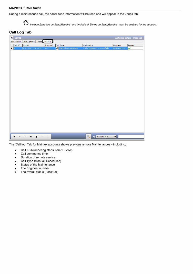
During a maintenance call, the panel zone information will be read and will appear in the Zones tab.
‘Include Zone text on Send/Receive’ and ‘Include all Zones on Send/Receive’ must be enabled for the account.
Call Log Tab
The ‘Call log’ Tab for Maintex accounts shows previous remote Maintenances – including;
• Call ID (Numbering starts from 1 – xxxx) • Call commence time • Duration of remote service • Call Type (Manual/ Scheduled) • Status of the Maintenance • The Engineer number • The overall status (Pass/Fail)

MAINTEX™ User Guide
INS571 19
Account icon status In the accounts tab on every account before the account ID number there is an Icon to help diagnose the status of each individual account,
This indicates a partially defined account. Insufficient data has been added for this account to be active.
This is the status indicated for a newly defined account, awaiting initial commissioning.
This is the status indicated for a account following successful commissioning, and also following automatic maintenance when new reports have been printed.
The page icon indicates a recent automatic or manual maintenance has been performed. It indicates that no errors were reported by the remote alarm panel, and that a new report is available for this account.
The highlighted warning triangle indicates an automatic or manual maintenance has been performed, where the remote alarm panel has detected one or more error conditions. The highlighting (red dashes) indicates that the report for last maintenance has not been printed.
The un-highlighted warning triangle is as per the above case, but where the last maintenance report has been printed.
The red background clock indicates that the scheduled automatic maintenance has not been performed for this account. This status is indicated approximately 15 minutes after the scheduled maintenance time.
The red X icon indicates a disabled account. These accounts do not appear in the scheduled or completed schedule views. Disabled accounts will not initiate automatic listen, or accept data input from panel to Maintex.
However historical reports may still be read and printed for these accounts by finding the account in the All schedule view and then viewing the History view for this account

MAINTEX™ User Guide
Accounts Overview Under the Heading of ‘Accounts’ in Maintex you can select an overview of all the accounts present within Maintex.
This will display the following basic information;
• Account ID (Created by Maintex) • Site Ref (Imported from Wintex) • Address field for the account • Telephone number of the account • IP address information for the account • IP Port information for the account • Status – this gives the operator a basic oversight of the accounts current state.
Double clicking on a highlighted account will take you to that accounts details page, where more information can be acquired.

MAINTEX™ User Guide
INS571 21
Maintenance Schedule & History Under the schedule option there are 4 categories > All/ Completed/Scheduled/History
ALL The Schedule ‘All’ view is similar to the Accounts Overview, all accounts are shown.
The emphasis of this view is the scheduled automatic maintenance date which sets the default sort order.
Accounts without a date set will appear at the top of account to indicate attention is required.
Whilst highlighted in the Schedule ‘All’ view the operator can service a control panel instantly by selecting the ‘Service Panel’ icon at the bottom of the form;
This will perform a full maintenance on the control panel via any of the shown connection options.

MAINTEX™ User Guide
Completed The Schedule ‘Completed’ view shows all accounts where automatic maintenance has been completed.
The emphasis of this view is the date and time that maintenance was completed, which sets the default sort order.
Scheduled The ‘Scheduled’ view is similar to the Schedule ‘All’ view, events are ordered by scheduled maintenance date.
The scheduled view only shows accounts that have been commissioned and have a forthcoming scheduled maintenance date.

MAINTEX™ User Guide
INS571 23
History The ‘History’ view shows the maintenance history for the selected account. The dates where maintenance has been recorded are shown in the grid on the left. Selection of a record (maintenance date) from the grid permits the various maintenance records (Overview, System Faults, Zones, Voltages and Currents and Panel Event Log) to be viewed.
A grid column indicates if a maintenance record has been printed.
Print report options for a selected maintenance date are print Selected maintenance overview, or print Faults for a selected maintenance date.
Printing the Selected maintenance overview record changes the grid status for the selected maintenance date from not printed to printed.

Remote Monitoring
Before being able to use the remote monitoring section of Maintex you will need to configure and test the modem – failure to do this will result in the following warning message;
Once you have selected "Monitor" it will then make the modem attached to the PC await a call to perform the remote Maintenance;
Before Monitor is enabled
After Monitor is enabled

MAINTEX™ User Guide
INS571 25
Commissioning an account Each site setup for Remote Maintenance must be commissioned. This action sets the maintenance date on the PC and in the control panel, and can either be initiated remotely from the PC or on site by the installing engineer. When using IP or Dial Capture (outgoing calls from the PC) the maintenance date for the panel is held in the PC. When the panel dials into the PC the maintenance date will be sent to the control panel.
When commissioning from site, it is highly recommended that you create unique ID's for each Engineer, see below this will then create an audit record to identify the Engineer who setup the maintenance schedule from the site.
Engineer Database
Creating Engineers ID An engineer ID can be programmed in Maintex for when the installer is using remote controls from the control panel to identify which installer is commissioning/requesting commands from the control panel to the office PC. (See:
Engineer ID is programmed in the following location;
Commissioning from site)
Operator (top tool bar) > Engineers DB
Use the + sign to add Engineers, enter and ID number for the engineer and their name.
Use the - symbol to delete and engineer.
When finished select Close
Commissioning from the PC
Select the account you want to commission from the accounts screen. Clicking the ‘Commission’ button starts commissioning the account with the communications method that was chosen during initial setup of the account – PSTN/ IP. This is a ‘quick’ method of commissioning an account, and leaves the control of the process with the office.

Commissioning from site Systems may be commissioned from site by the installing/commissioning engineer. The process is initiated from the system keypad via a number of commands.
The on-site engineer should be given the Maintex account number for the site he is working on.
Premier 24 When using the Commission mode on a Premier 24, call back No.2 should be used. Call-back No.2 can be programmed on the control panel under Communication Options/UDL Options. The number programmed should be the telephone number for the Remote PC.
Premier 48/88/168 When using the Commission mode on a Premier 48/88/168, call back No.3 should be used. Call-back No.3 can be programmed on the control panel under Communication Options/UDL Options. The number programmed should be the telephone number for the Remote PC.
The Premier 640 is NOT supported by Maintex.
Premier Elite 12/24/48/88/168 & 640 When using the Commission mode on a Premier Elite 24/48/88/168 & 640, call back No.3 should be used. Call-back No.3 can be programmed on the control panel under Communication Options/UDL Options. The number programmed should be the telephone number for the Remote PC.
Keypad Command Structure [Remote PC Tel No]#$$[Account No]E[Engineer ID] e.g. 01706233875#M1234E987
Office Tel No The Maintex modem telephone number.
#$$ A hash character followed by a one or two character command (see Command Table).
Account No This is the account number used by Maintex. You only need to enter this the first time you communicate with the Maintex. Thereafter, it can be omitted from the command sequence.
E An optional command to indicate the Engineer ID is included in the command sequence.
Engineer ID: A one, two or three digit ID of the engineer who is making the call to the office. The engineer ID and name are allocated in Maintex.
Maintex Command Table
Command Name Function
#C Commission Synchronises the control panel Time & Date and sets the Time & Dates for the next maintenance call.
#S Save Uploads the control panel program data and saves a copy of the data in the account profile on the Remote PC.
#L Load Downloads the control panel program data from the Remote PC to the panel on-site
#CS Commission & Save Performs a Commission & Save command as described above but in one call.
#CL Commission & Load Performs a Commission & Load command as described above but in one call.
#M Maintenance Forces a remote maintenance call to occur and sets the Time & Date for the next remote maintenance call.

MAINTEX™ User Guide
INS571 27
Debug View Maintex provides a Debug function to allow viewing of all the data that is being sent/ received.
To access this section you will need to select from the top tool bar ‘Comms’ > ‘Debug’
The following screen will be opened;
The top screen displayed will show information for the connections and commissioning as they take place.
You can select what will be displayed in the window be selecting or deselecting the following;
• Raw Data • Command Text • Modem Events • Header Info • Verbal • RX Data
Below is an example screen;
The second debug window will detail communising data in a processed format – see below screen also as an example;

Texecom Limited, Bradwood Court, St. Crispin Way, Haslingden, Lancashire BB4 4PW, England. Technical Support:
UK Customers Tel: 08456 300 600 (Calls charged at 3.36 pence per minute from a BT landline. Calls from other networks may vary.)
International Customers Tel: +44 1706 233875 Email: [email protected]
© Texecom Limited 2013 INS571