wire-edm - seekpartfile.seekpart.com/keywordpdf/2010/12/23/2010122392836484.pdfwire-edm gibbscam...
TRANSCRIPT
EDM Manual.book Page a Wednesday, May 31, 2006 1:14 PM
Wire-EDMGibbsCAM 2006
May 2006

EDM Manual.book Page b Wednesday, May 31, 2006 1:14 PM
ProprietaryNoticeThis document contains propriety information of Gibbs and Associates and is to be used only pursu-ant to and in conjunction with the license granted to the licensee with respect to the accompanying Gibbs and Associates licensed software. Except as expressly permitted in the license, no part of this document may be reproduced, transmitted, transcribed, stored in a retrieval system, or translated into any language or computer language, in any form or by any means, electronic, magnetic, optical, chemical, manual or otherwise, without the prior expressed written permission from Gibbs and Asso-ciates or a duly authorized representative thereof.
It is strongly advised that users carefully review the license in order to understand the rights and obli-gations related to this licensed software and the accompanying documentation.
Use of the computer software and the user documentation has been provided pursuant to a Gibbs and Associates licensing agreement.
© Copyright 2001-2006 Gibbs and Associates, Inc. All rights reserved. The Gibbs logo,GibbsCAM, GibbsCAM logo, Virtual Gibbs, Gibbs SFP, MTM, SolidSurfacer, and “PowerfullySimple. Simply Powerful.” are either trademark(s) or registered trademark(s) of Gibbs andAssociates in the United States and/or other countries. Windows is a registered trademark ofMicrosoft Corporation in the United States and other countries. All other brand or productnames are trademarks or registered trademarks of their respective owners. Contains Autodesk®RealDWG by Autodesk, Inc., Copyright © 1998-2006 Autodesk, Inc. All rights reserved.
Acknowledgements:Written by Wil Gaffga, Lori Turner & Mike O’NeillThanks to Bill Gibbs, Steve Aughinbaugh & Mario Guerrero for their input and assistance.
Printed in the United States of America
Gibbs and Associates323 Science Drive
Moorpark, CA 93021
Modified: 5/30/06

Table of Contents
Table of Contents
EDM Manual.book Page i Wednesday, May 31, 2006 1:14 PM
GENERAL INFORMATION 1
What Is Wire EDM? . . . . . . . . . . . . . . . . . . . . . . . . . . . . . . . . . . . . . . . . . . . . . . . . . . . . . . . . . . . . . . . . . . 3Wire EDM Package Overview. . . . . . . . . . . . . . . . . . . . . . . . . . . . . . . . . . . . . . . . . . . . . . . . . . . . . . . . . . 4Wire EDM Package Detail . . . . . . . . . . . . . . . . . . . . . . . . . . . . . . . . . . . . . . . . . . . . . . . . . . . . . . . . . . . . . 5
USE AND REFERENCE 7
Overview . . . . . . . . . . . . . . . . . . . . . . . . . . . . . . . . . . . . . . . . . . . . . . . . . . . . . . . . . . . . . . . . . . . . . . . . . . . 9Interface. . . . . . . . . . . . . . . . . . . . . . . . . . . . . . . . . . . . . . . . . . . . . . . . . . . . . . . . . . . . . . . . . . . . . . . . . . . . 9
Menu Items . . . . . . . . . . . . . . . . . . . . . . . . . . . . . . . . . . . . . . . . . . . . . . . . . . . . . . . . . . . . . . . . . . . . . 11File Menu . . . . . . . . . . . . . . . . . . . . . . . . . . . . . . . . . . . . . . . . . . . . . . . . . . . . . . . . . . . . . . . . . . . . 12Dimension Menu. . . . . . . . . . . . . . . . . . . . . . . . . . . . . . . . . . . . . . . . . . . . . . . . . . . . . . . . . . . . . . 13Info Menu. . . . . . . . . . . . . . . . . . . . . . . . . . . . . . . . . . . . . . . . . . . . . . . . . . . . . . . . . . . . . . . . . . . . 13Settings Menu . . . . . . . . . . . . . . . . . . . . . . . . . . . . . . . . . . . . . . . . . . . . . . . . . . . . . . . . . . . . . . . . 14Display . . . . . . . . . . . . . . . . . . . . . . . . . . . . . . . . . . . . . . . . . . . . . . . . . . . . . . . . . . . . . . . . . . . . . . 16Help . . . . . . . . . . . . . . . . . . . . . . . . . . . . . . . . . . . . . . . . . . . . . . . . . . . . . . . . . . . . . . . . . . . . . . . . 17
Toolbar. . . . . . . . . . . . . . . . . . . . . . . . . . . . . . . . . . . . . . . . . . . . . . . . . . . . . . . . . . . . . . . . . . . . . . . . . 18Display Commands . . . . . . . . . . . . . . . . . . . . . . . . . . . . . . . . . . . . . . . . . . . . . . . . . . . . . . . . . . . . 18Configuration . . . . . . . . . . . . . . . . . . . . . . . . . . . . . . . . . . . . . . . . . . . . . . . . . . . . . . . . . . . . . . . . 19View Commands . . . . . . . . . . . . . . . . . . . . . . . . . . . . . . . . . . . . . . . . . . . . . . . . . . . . . . . . . . . . . . 20Undo/Redo . . . . . . . . . . . . . . . . . . . . . . . . . . . . . . . . . . . . . . . . . . . . . . . . . . . . . . . . . . . . . . . . . . 21Solid Rendering . . . . . . . . . . . . . . . . . . . . . . . . . . . . . . . . . . . . . . . . . . . . . . . . . . . . . . . . . . . . . . . 21Return to GibbsCAM . . . . . . . . . . . . . . . . . . . . . . . . . . . . . . . . . . . . . . . . . . . . . . . . . . . . . . . . . . 22
Top Level Palette . . . . . . . . . . . . . . . . . . . . . . . . . . . . . . . . . . . . . . . . . . . . . . . . . . . . . . . . . . . . . . . . . 23Wire Strategy/Configuration. . . . . . . . . . . . . . . . . . . . . . . . . . . . . . . . . . . . . . . . . . . . . . . . . . . . 23Machining . . . . . . . . . . . . . . . . . . . . . . . . . . . . . . . . . . . . . . . . . . . . . . . . . . . . . . . . . . . . . . . . . . . 24Add or Edit Gluestops . . . . . . . . . . . . . . . . . . . . . . . . . . . . . . . . . . . . . . . . . . . . . . . . . . . . . . . . . . 24Modify Taper . . . . . . . . . . . . . . . . . . . . . . . . . . . . . . . . . . . . . . . . . . . . . . . . . . . . . . . . . . . . . . . . . 25Specify Conic or Cylindrical Radius . . . . . . . . . . . . . . . . . . . . . . . . . . . . . . . . . . . . . . . . . . . . . . . 25Sync . . . . . . . . . . . . . . . . . . . . . . . . . . . . . . . . . . . . . . . . . . . . . . . . . . . . . . . . . . . . . . . . . . . . . . . . 26No-Core Cutting . . . . . . . . . . . . . . . . . . . . . . . . . . . . . . . . . . . . . . . . . . . . . . . . . . . . . . . . . . . . . . 26Edit or Modify Geometry . . . . . . . . . . . . . . . . . . . . . . . . . . . . . . . . . . . . . . . . . . . . . . . . . . . . . . . 26Dimensions . . . . . . . . . . . . . . . . . . . . . . . . . . . . . . . . . . . . . . . . . . . . . . . . . . . . . . . . . . . . . . . . . . 26Information . . . . . . . . . . . . . . . . . . . . . . . . . . . . . . . . . . . . . . . . . . . . . . . . . . . . . . . . . . . . . . . . . . 27Resequence the Operations . . . . . . . . . . . . . . . . . . . . . . . . . . . . . . . . . . . . . . . . . . . . . . . . . . . . . 27Operation Sheet. . . . . . . . . . . . . . . . . . . . . . . . . . . . . . . . . . . . . . . . . . . . . . . . . . . . . . . . . . . . . . . 28Machining Simulation . . . . . . . . . . . . . . . . . . . . . . . . . . . . . . . . . . . . . . . . . . . . . . . . . . . . . . . . . . 29Create CNC code. . . . . . . . . . . . . . . . . . . . . . . . . . . . . . . . . . . . . . . . . . . . . . . . . . . . . . . . . . . . . . 30
Using the Package - Detail . . . . . . . . . . . . . . . . . . . . . . . . . . . . . . . . . . . . . . . . . . . . . . . . . . . . . . . . . . . . 31
i

Table of Contents
EDM Manual.book Page ii Wednesday, May 31, 2006 1:14 PM
Wire Configuration/Strategy . . . . . . . . . . . . . . . . . . . . . . . . . . . . . . . . . . . . . . . . . . . . . . . . . . . . . . . 31Wire Configuration - Machine Configuration Tab . . . . . . . . . . . . . . . . . . . . . . . . . . . . . . . . . . . 31
Machine 32Wire diameter. . . . . . . . . . . . . . . . . . . . . . . . . . . . . . . . . . . . . . . . . . . . . . . . . . . . . . . . . . . . . . . . . 36Wire guides . . . . . . . . . . . . . . . . . . . . . . . . . . . . . . . . . . . . . . . . . . . . . . . . . . . . . . . . . . . . . . . . . . . 36Material . . . . . . . . . . . . . . . . . . . . . . . . . . . . . . . . . . . . . . . . . . . . . . . . . . . . . . . . . . . . . . . . . . . . . . 36Output Z Planes . . . . . . . . . . . . . . . . . . . . . . . . . . . . . . . . . . . . . . . . . . . . . . . . . . . . . . . . . . . . . . . 37Part Orientation . . . . . . . . . . . . . . . . . . . . . . . . . . . . . . . . . . . . . . . . . . . . . . . . . . . . . . . . . . . . . . . 37Check Travel Limits When Creating Code. . . . . . . . . . . . . . . . . . . . . . . . . . . . . . . . . . . . . . . . . . 37Advanced Settings . . . . . . . . . . . . . . . . . . . . . . . . . . . . . . . . . . . . . . . . . . . . . . . . . . . . . . . . . . . . . 38Machining Report. . . . . . . . . . . . . . . . . . . . . . . . . . . . . . . . . . . . . . . . . . . . . . . . . . . . . . . . . . . . . . 39Wire Configuration - Machining Strategy Tab . . . . . . . . . . . . . . . . . . . . . . . . . . . . . . . . . . . . . . 40Skim cut direction . . . . . . . . . . . . . . . . . . . . . . . . . . . . . . . . . . . . . . . . . . . . . . . . . . . . . . . . . . . . . 40
Skim cut transition 41Gluestop Removal: 41Multiple Parts: 42Parts with Land: 44Corner Loop and Corner Relief: 44
Wire Configuration - Display Settings Tab: . . . . . . . . . . . . . . . . . . . . . . . . . . . . . . . . . . . . . . . . . 45Display Settings: 46Show / Hide: 46Wire guide display: 46Simulation Speed: 46Viewport Selection: 46Display datums: 46
Agie machines . . . . . . . . . . . . . . . . . . . . . . . . . . . . . . . . . . . . . . . . . . . . . . . . . . . . . . . . . . . . . . . . . . . 47AGIE Output . . . . . . . . . . . . . . . . . . . . . . . . . . . . . . . . . . . . . . . . . . . . . . . . . . . . . . . . . . . . . . . . . . . . 49Charmilles CT machines . . . . . . . . . . . . . . . . . . . . . . . . . . . . . . . . . . . . . . . . . . . . . . . . . . . . . . . . . . . 51Creating a Wire EDM Part . . . . . . . . . . . . . . . . . . . . . . . . . . . . . . . . . . . . . . . . . . . . . . . . . . . . . . . . . 52Add or Edit a GlueStop . . . . . . . . . . . . . . . . . . . . . . . . . . . . . . . . . . . . . . . . . . . . . . . . . . . . . . . . . . . . 55Modify Taper Angle . . . . . . . . . . . . . . . . . . . . . . . . . . . . . . . . . . . . . . . . . . . . . . . . . . . . . . . . . . . . . . . 56Wire Synchronization . . . . . . . . . . . . . . . . . . . . . . . . . . . . . . . . . . . . . . . . . . . . . . . . . . . . . . . . . . . . . 57No-Core Cutting . . . . . . . . . . . . . . . . . . . . . . . . . . . . . . . . . . . . . . . . . . . . . . . . . . . . . . . . . . . . . . . . . 57
Number of cuts: 57Overlap: 58
Dimensioning the Part. . . . . . . . . . . . . . . . . . . . . . . . . . . . . . . . . . . . . . . . . . . . . . . . . . . . . . . . . . . . . 59Information . . . . . . . . . . . . . . . . . . . . . . . . . . . . . . . . . . . . . . . . . . . . . . . . . . . . . . . . . . . . . . . . . . . . . 60Resequence the Operations. . . . . . . . . . . . . . . . . . . . . . . . . . . . . . . . . . . . . . . . . . . . . . . . . . . . . . . . . 62Machining Simulation . . . . . . . . . . . . . . . . . . . . . . . . . . . . . . . . . . . . . . . . . . . . . . . . . . . . . . . . . . . . . 62Creating CNC Code. . . . . . . . . . . . . . . . . . . . . . . . . . . . . . . . . . . . . . . . . . . . . . . . . . . . . . . . . . . . . . . 63
Right-Click Editing . . . . . . . . . . . . . . . . . . . . . . . . . . . . . . . . . . . . . . . . . . . . . . . . . . . . . . . . . . . . . . . . . . 64Post Processing Enhancements. . . . . . . . . . . . . . . . . . . . . . . . . . . . . . . . . . . . . . . . . . . . . . . . . . . . . . . . . 66creating your own posts . . . . . . . . . . . . . . . . . . . . . . . . . . . . . . . . . . . . . . . . . . . . . . . . . . . . . . . . . . . . . . 67
ii

Table of Contents
EDM Manual.book Page iii Wednesday, May 31, 2006 1:14 PM
About creating your own posts . . . . . . . . . . . . . . . . . . . . . . . . . . . . . . . . . . . . . . . . . . . . . . . . . . . . . 67Valid Variable Definitions . . . . . . . . . . . . . . . . . . . . . . . . . . . . . . . . . . . . . . . . . . . . . . . . . . . . . . . 68
Drilling. . . . . . . . . . . . . . . . . . . . . . . . . . . . . . . . . . . . . . . . . . . . . . . . . . . . . . . . . . . . . . . . . . . . . . . . . . . . 68
TUTORIALS 69
Tutorial #1 Wire EDM 2-Axis . . . . . . . . . . . . . . . . . . . . . . . . . . . . . . . . . . . . . . . . . . . . . . . . . . . . . . . . . 71Tutorial #2 Wire EDM 4-axis . . . . . . . . . . . . . . . . . . . . . . . . . . . . . . . . . . . . . . . . . . . . . . . . . . . . . . . . . 79Tutorial #3 Wire EDM Open Profile . . . . . . . . . . . . . . . . . . . . . . . . . . . . . . . . . . . . . . . . . . . . . . . . . . . 92
INDEX 101
iii

Table of Contents
EDM Manual.book Page iv Wednesday, May 31, 2006 1:14 PM
iv
GENERAL INFORMATION
EDM Manual.book Page 1 Wednesday, May 31, 2006 1:14 PM

EDM Manual.book Page 2 Wednesday, May 31, 2006 1:14 PM

General Information
CHAPTER 1
: Gen e r a l I n f o rma t i o n
EDM Manual.book Page 3 Wednesday, May 31, 2006 1:14 PM
WHAT IS WIRE EDM?Wire EDM (Electric Discharge Machining) is a process by which stock is cut by the means of a gapbeing burned through the material by the heat produced by electrical sparks between the stock and awire. The part and wire are immersed in a dielectric (electrically nonconducting) fluid which also actsas a coolant and flushes away debris.
1 - A charged wire approaches the workpiece in a dielectric fluid.2 - At a certain distance, the charge arcs to the workpiece3 - The wire and workpiece are heated and a vacuum is formed.4 - Material is stripped off the wire and the workpiece.5 - There is a small implosion and more material is removed from the workpiece and wire.
Figure 1: Example of how Wire EDM cuts through material.
3
General Information
EDM Manual.book Page 4 Wednesday, May 31, 2006 1:14 PM
WIRE EDM PACKAGE OVERVIEWThe Wire EDM package works in conjunction with GibbsCAM and not as a stand-alone product. It isintended to be used as a supplement to existing milling and/or turning clients. To this end, it includesfunctionality to produce most 2-axis parallel, 2-axis tapered and 4-axis parts. A key feature is the easeof use; therefore, some functions which are only required for special one-off situations are not directlyimplemented. This is to keep the interface uncluttered and to retain the ease of use. As for mostthings, there will normally be a work-around to handle these odd situations.
The Wire EDM package is designed to produce Wire EDM toolpath from GibbsCAM geometry.Given the fact that EDM is quite different from milling or turning, the Wire EDM package is a self-contained module that includes machining, simulation and code creation.
Using the package you will be able to create punches or dies (closed parts) and:
2-axis parts, with parallel walls
2-axis tapered parts, with or without parallel land
4-axis parts, with or without land
Machine open shapes using 2-axis cuts
The 4-axis parts require two 2-axis profiles that represent the top and bottom of the tapered part of thecomponent. Each closed part can have a user-specified number of rough/skim cuts and may have oneor more gluestops.
You can machine a single part or multiple parts with Wire EDM. When more than one part isrequired, an overall machining strategy will dictate how the sequence of machining will occur. Thiswill include the option to complete each part, rough each part first or rough and skim each part first.
As for the removal of gluestops, an overall strategy indicates whether they are removed after the initialrough cut, after all skim cuts, or left in the part for manual removal.
It should be noted that the Wire EDM product is a system that deals solely with the machining of wireparts and contains minimal geometry creation or editing facilities. Most geometry creation or editingmust be done within GibbsCAM.
4
General Information
EDM Manual.book Page 5 Wednesday, May 31, 2006 1:14 PM
WIRE EDM PACKAGE DETAILThis product has been designed with ease of use as a priority. In GibbsCAM, you select the geometrythat represent the parts to be cut, then load the geometry into the Wire EDM product where you canindicate how each part is machined, view the toolpath simulation and create CNC code.
To create a wire part, you must first define the geometry that represents the part boundaries withinGibbsCAM using standard 2-axis geometry. Next, select all of the geometry required to define thewire part(s), including points for gluestop start locations. Wire EDM is designed to apply machining to2D profiles; therefore, the only geometry entities it requires are 2D lines, arcs, circles and points. Oncethe geometry is selected, click on the Launch EDM option from the GibbsCAM Wire EDM menu toswitch to the Wire EDM package.
The Wire EDM package interface is a complete window that covers the GibbsCAM window. Theinterface is similar to GibbsCAM but is designed for Wire EDM work.
The main functions within Wire EDM are:
Wire Strategy: Defining the overall machining strategy, including:
Part orientation—land on top or bottom.
How gluestops are removed—after rough cuts, after skim cuts or manually.
How multiple parts are machined—complete each part, rough cuts first or rough/skim first.
How skim cuts are transitioned to change offsets—either by adding small lines off/on thepart, or tangential arc off/on.
Machine configuration—travel limits, wire guide limits.
Machine a part
Select a profile and indicate the start point of the wire for the first gluestop.
Indicate how many and which rough/skim cuts are to be used for the selected part.
Specify gluestop width.
Specify first element to be machined on the profile.
Select part type as either parallel, tapered (with optional land) or 4-axis (with optional land).For a 4-axis part, a second profile must be selected to represent the bottom of the part
5

General Information
EDM Manual.book Page 6 Wednesday, May 31, 2006 1:14 PM
Add a gluestop
Add an additional gluestop to a machined part. Select the element for the gluestop, the startpoint and the gluestop width.
Modify the taper angle of an individual element.
Select any element on a 2-axis tapered part and you can change the angle of taper for thatelement only. Note that if the element is an arc, then the elements immediately before andafter the arc must also be changed.
Using the Wire EDM product, you are able to machine either a single part or multiple parts. Each partcan be either a 2-axis part with parallel walls, 2-axis tapered (with or without land) or 4-axis (againwith or without land cuts).
The product enables you to allocate attributes to each part and to specify an overall strategy for allparts.
Attributes applying to each part include:
• The number of skim cuts• The number of gluestops (and their respective locations)• The type of part (2-axis, 2-axis tapered, 4-axis, etc.)• The direction around the partThe overall machining strategy covers:
• When gluestops are removed - after the first roughing cut, after all the skim cuts, or not removed at all (manuallyremoved)
• If all cuts are the same direction around each part, or alternate skim cuts are reversed (to reduce the number oftimes the wire need to be broken and re-threaded)
• How offsets are changed between each skim cut (by adding small moves away from the part and back on again)• Whether all of each part is completed before moving to the next one, or if all parts are roughed and then skimmedThe strategy can be changed at any time and the toolpath will automatically be updated to reflect thechanges.
6
USE AND REFERENCE
EDM Manual.book Page 7 Wednesday, May 31, 2006 1:14 PM

EDM Manual.book Page 8 Wednesday, May 31, 2006 1:14 PM
Use and Reference
CHAPTER 2
: U s e a n d R e f e r e n c e
EDM Manual.book Page 9 Wednesday, May 31, 2006 1:14 PM
OVERVIEWGibbsCAM Wire EDM is able to machine both open and closed profiles and create 2-axis or 4-axisparts.
• Each 2-axis part (parallel or tapered walls) requires a single closed profile and a point to represent the start position(wire thread location).
• Each 4-axis part requires two closed profiles, one to represent the top of the part and one to represent the bottom.You will also need a point for each gluestop start position.
• Open profiles may be machined, but these can only be done with parallel or tapered cuts (not 4-axis). They do notneed a gluestop (it is optional) and only require a point for the wire thread position if the wire starts away from theprofile.
You are also able to create No-Core Cutting. This functionality enables you to either remove a free-formshape or circular hole. Free-form shapes require a closed profile and a point for the wire start position,and holes simply require a circle.
Within GibbsCAM, you select the profiles and points required to define each part together with anyprofiles and/or circles for No-Core cuts. Click on Launch EDM from the Wire EDM menu and you will beautomatically taken into the Wire EDM product.
INTERFACEThe Wire EDM interface resembles the GibbsCAM interface and uses both icons and pull-downmenus. Virtually everything is done by using the icons at the top and right of the screen, but a list ofthe pull-down menu options is included for completeness. If you leave the mouse over an icon, youwill get a short Tooltip describing the functionality of the icon. By right-clicking on an icon you willget a more detailed description.
Most of the screen area, the Workspace, is reserved for graphics. Like in GibbsCAM, the stock area isdisplayed with grid lines. At the bottom of the screen area are 2 boxes. Each time you select a
TIP
If you do not select any geometry before clicking on the EDM option, you will begiven the opportunity to start the EDM package without transferring anygeometry—this is useful if you want to check/modify a previously saved WireEDM program.
9

Use and Reference
EDM Manual.book Page 10 Wednesday, May 31, 2006 1:14 PM
command that requires input, the name of the command will be displayed in the first box and the typeof input required will be displayed in the second box.
Figure 1: Elements of the Wire EDM interface.
1 - Menu2 - Toolbar
3 - Top Level palette4 - Workspace
5 - Input requirements6 - Mouse Position
10

Use and Reference
EDM Manual.book Page 11 Wednesday, May 31, 2006 1:14 PM
MENU ITEMSThe pull-down menus at the top of the screen contain the following functions:
11
Use and Reference
EDM Manual.book Page 12 Wednesday, May 31, 2006 1:14 PM
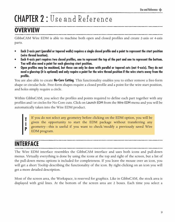
File MenuRevert to original data: Reverts back to original geometry fromGibbsCAM. All functions, commands and processes that you haveexecuted will be erased.Open part: Open a previously saved Wire EDM part.Save part: Save current part.Save part as : Save current part as a new filename.Notes: Select this item to enter data about the part file.
Copy (clipboard): Copy graphics to clipboard.Print: The Print sub-menu provides access to several printoptions. Print current view: Print current view.Print part full size: Print entire full sized part.
Plot to scale : Brings up a dialog in which you can select orenter the exact scale at which you wish to plot or print.Printer set-up: Change printer settings.
12
Use and Reference
EDM Manual.book Page 13 Wednesday, May 31, 2006 1:14 PM
Dimension Menu
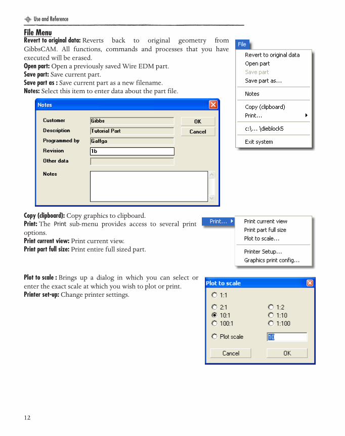
Info MenuMeasure: Measure the distance between two points. Select thetwo points and an alert dialog will open with the datarequested
Area/perimeter: Calculate the area/perimeter of a profile. Selectthe closed shape and an alert dialog will open with the datarequested.
Graphics print config: Configure how graphics areprinted.Exit System: Exit Wire-EDM and return to GibbsCam.
XY Point: XY position of a point.Line horizontal: Dimension a line using its horizontal distance (X).Line vertical : Dimension a line using its vertical distance (Y).Line parallel : Dimension a line using actual line length.2 pts horizontal : Dimension between two points (horizontal distance).2 pts vertical: Dimension between two points (vertical distance).2 pts parallel: Dimension between two points (actual distance).Angle of line : Dimension the angle of one line.Angle 2 lines: Dimension angle between two lines.Arc radius: Dimension the radius of an arc.Arc angle : Dimension the included angle of an arc.Configure: Configure dimension text height and decimal places.
For more details on Dimensions see page 23.
13

Use and Reference
EDM Manual.book Page 14 Wednesday, May 31, 2006 1:14 PM
Calculator: Brings up the desktop calculator that includes memory/recall and trig functions.
Settings MenuPoints : Show/hide gluestop start points/circles.Dimensions: Show/hide dimensions.Axes: Show/hide axes (XY, XZ or YZ) symbol.
Language: Select operating language.Interface: Select the interface style you prefer to work with. Gibbs style -fixed is the default and locks the Top Level palette in the top rightcorner. Gibbs style - floating unlocks the Top Level palette so it may beplaced anywhere on your screen.
14

Use and Reference
EDM Manual.book Page 15 Wednesday, May 31, 2006 1:14 PM
Setup post editor: Allows the user to assign specific preferences for post editing.
Setup Technology data: This dialog allows you to define a list of material types, wire types and wirediameters. In Wire strategy/configuration settings, drop down menus are used to select material andwire. The corresponding technology data entered here will be automatically loaded into those lists.
15
Use and Reference
EDM Manual.book Page 16 Wednesday, May 31, 2006 1:14 PM
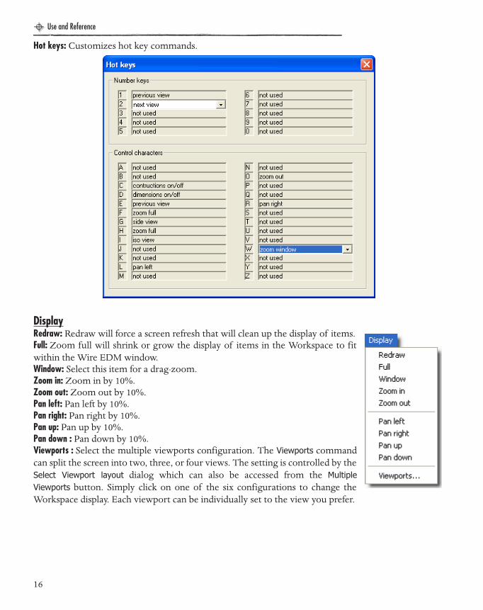
Hot keys: Customizes hot key commands.
DisplayRedraw: Redraw will force a screen refresh that will clean up the display of items.Full: Zoom full will shrink or grow the display of items in the Workspace to fitwithin the Wire EDM window.Window: Select this item for a drag-zoom.Zoom in: Zoom in by 10%.Zoom out: Zoom out by 10%.Pan left: Pan left by 10%.Pan right: Pan right by 10%.Pan up: Pan up by 10%.Pan down : Pan down by 10%.Viewports : Select the multiple viewports configuration. The Viewports commandcan split the screen into two, three, or four views. The setting is controlled by theSelect Viewport layout dialog which can also be accessed from the MultipleViewports button. Simply click on one of the six configurations to change theWorkspace display. Each viewport can be individually set to the view you prefer.
16

Use and Reference
EDM Manual.book Page 17 Wednesday, May 31, 2006 1:14 PM
HelpAbout GibbsCAM Wire EDM: Displays information about the product and theversion currently being used.
Posts : Displays a help window (shown below) with topics relating toEDM post processing.
17

Use and Reference
EDM Manual.book Page 18 Wednesday, May 31, 2006 1:14 PM
TOOLBARThe Toolbar provides quick access to commonly used commands such as setting the display and viewsettings, part configuration and undo/redo functions.
Display CommandsThe first four buttons control the display of items in the Workspace, similar toseveral of the items in the GibbsCAM View palette. These commands includeRedraw, Zoom Full, Zoom In and Zoom Out.
Redraw: Redraw will force a screen refresh that will clean up the display of items.
Zoom Full : Zoom Full will shrink or grow the display of items in the Workspace to fit within the WireEDM window.
Zoom In: The Zoom In command will increase the display of items in the Workspace by 10%. You mayalso Zoom In on the part by using Shift + “+” or the mouse wheel or by dragging the mouse on anarea that you want to zoom in on.
Zoom Out: The Zoom Out command will decrease the display of items in the Workspace by 10%. Youmay also Zoom Out on the part by using Shift - “-” or the mouse wheel.
In addition, Ctrl + arrow keys will pan the part in the specified direction. Right-clicking a part anddragging it will also move it in the specified direction.
1 - Display Commands2 - Configuration3 - View Commands
4 - Undo / Redo5 - Miscellaneous Commands6 - Solid Rendering
7 - Return to GibbsCAM
18
Use and Reference
EDM Manual.book Page 19 Wednesday, May 31, 2006 1:14 PM
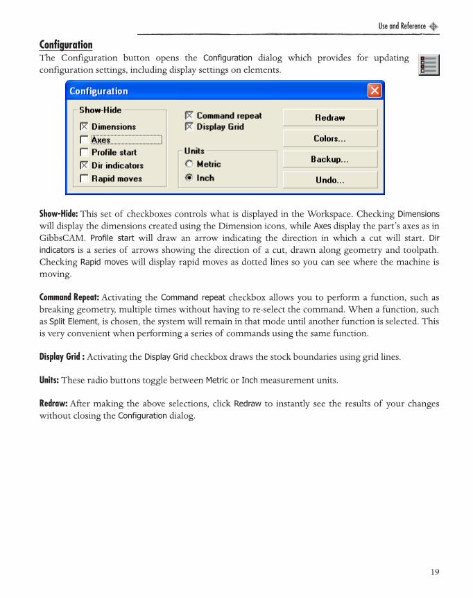
ConfigurationThe Configuration button opens the Configuration dialog which provides for updatingconfiguration settings, including display settings on elements.
Show-Hide: This set of checkboxes controls what is displayed in the Workspace. Checking Dimensionswill display the dimensions created using the Dimension icons, while Axes display the part’s axes as inGibbsCAM. Profile start will draw an arrow indicating the direction in which a cut will start. Dirindicators is a series of arrows showing the direction of a cut, drawn along geometry and toolpath.Checking Rapid moves will display rapid moves as dotted lines so you can see where the machine ismoving.
Command Repeat: Activating the Command repeat checkbox allows you to perform a function, such asbreaking geometry, multiple times without having to re-select the command. When a function, suchas Split Element, is chosen, the system will remain in that mode until another function is selected. Thisis very convenient when performing a series of commands using the same function.
Display Grid : Activating the Display Grid checkbox draws the stock boundaries using grid lines.
Units: These radio buttons toggle between Metric or Inch measurement units.
Redraw: After making the above selections, click Redraw to instantly see the results of your changeswithout closing the Configuration dialog.
19

Use and Reference
EDM Manual.book Page 20 Wednesday, May 31, 2006 1:14 PM
Colors: This dialogallows you toconfigure thedisplay colors ofthe Wire EDMsystem. Click onthe name of theitem to changethe color. CheckUse wire color foreach wire cut tobe rendered in adifferent color (ifunchecked, allmachining isrendered in the same color).
Backup: This setting allows you to designate the backup file and frequency of backups. Select theAutobackup enabled checkbox to activate this function.
Undo: This setting allows you to set the number and types of undos the system tracks.
View CommandsThe View control buttons set the view orientation of the partgeometry. Settings include Plan, Front, Side, Isometric, MultipleViewports, and Mouse View Rotation.
Plan: The Plan button sets the view to the top of the part, looking down on the XY plane.
Front : The Front button sets the view to the front of the part, looking at the XZ plane.
20

Use and Reference
EDM Manual.book Page 21 Wednesday, May 31, 2006 1:14 PM
Side: The Side button sets the view to the top of the part, looking at the YZ plane.
Isometric view : The Isometric button sets the view to a three-axis view of the part. While in isometricview, click the Dynamic Rotation button and the cursor will change into an axes icon when it ispositioned over the part in isometric view. Left-click and hold the mouse button to dynamically rotatethe view. Remember to deactivate this feature after you have finished with it by right clicking or byclicking on the icon again.
Multiple Viewports: The Multiple Viewports button can split the screen into two, three, or four views. Thesetting is controlled by the Select viewport layout dialog which is accessed from the Multiple Viewportsbutton. Simply click on one of the six configurations to change the Workspace display. Each viewportcan be individually set to the view you prefer.
Undo/RedoThe Undo and Redo buttons allow you to remove changes on a part. The undone changescan also be re-done. The Undo command logs the last 100 modifications made to the partfile including syncs, geometry changes and machining functions. The Undo function maybe fine tuned or disabled in the Configuration dialog.
Figure 2: The Select viewport layout dialog and a part displayed with multiple viewports
21
Use and Reference
EDM Manual.book Page 22 Wednesday, May 31, 2006 1:14 PM
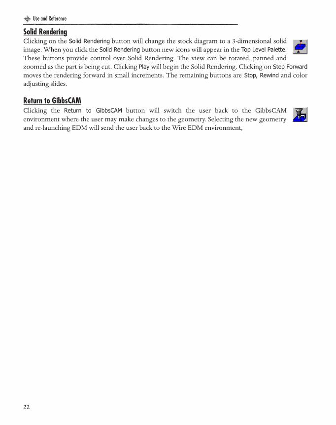
Solid RenderingClicking on the Solid Rendering button will change the stock diagram to a 3-dimensional solidimage. When you click the Solid Rendering button new icons will appear in the Top Level Palette.These buttons provide control over Solid Rendering. The view can be rotated, panned andzoomed as the part is being cut. Clicking Play will begin the Solid Rendering. Clicking on Step Forwardmoves the rendering forward in small increments. The remaining buttons are Stop, Rewind and coloradjusting slides.
Return to GibbsCAMClicking the Return to GibbsCAM button will switch the user back to the GibbsCAMenvironment where the user may make changes to the geometry. Selecting the new geometryand re-launching EDM will send the user back to the Wire EDM environment,
22
Use and Reference
EDM Manual.book Page 23 Wednesday, May 31, 2006 1:14 PM
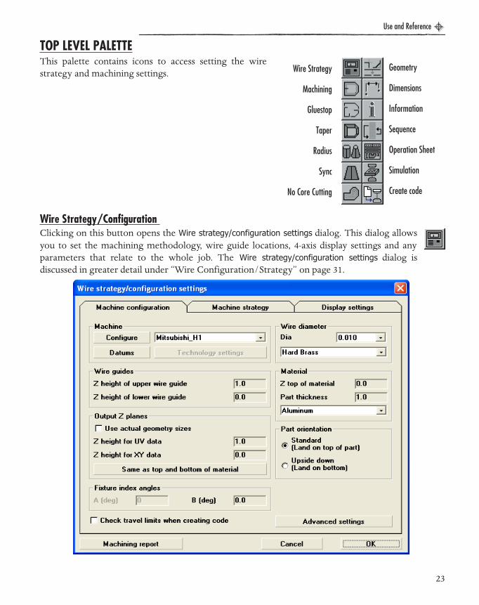
TOP LEVEL PALETTEThis palette contains icons to access setting the wirestrategy and machining settings.
Wire Strategy/Configuration Clicking on this button opens the Wire strategy/configuration settings dialog. This dialog allowsyou to set the machining methodology, wire guide locations, 4-axis display settings and anyparameters that relate to the whole job. The Wire strategy/configuration settings dialog isdiscussed in greater detail under “Wire Configuration/Strategy” on page 31.
Wire Strategy
Machining
Gluestop
Taper
Radius
Sync
No Core Cutting
Geometry
Dimensions
Information
Sequence
Operation Sheet
Simulation
Create code
23

Use and Reference
EDM Manual.book Page 24 Wednesday, May 31, 2006 1:14 PM
Machining Clicking on this button allows you to create or edit a wire part. Select the geometry thatrepresents the profile to be cut. On 4-axis parts, the top profile should be selected. Moreinformation may be found in the section “Creating a Wire EDM Part” on page 52.
Add or Edit GluestopsClicking on this button allows you to add, edit or delete a gluestop. Select an element (line orarc) on an existing wire part where you require an additional gluestop to be created. Select thestart point for the wire and a gluestop will be added. If you select an element that represents anexisting gluestop, you will be able to change the gluestop attributes (gluestop width) or to remove thegluestop altogether. More information may be found in the section “Add or Edit a GlueStop” onpage 55.
24

Use and Reference
EDM Manual.book Page 25 Wednesday, May 31, 2006 1:14 PM
Modify Taper Clicking on this button enables you to modify the taper angle of individual or a range ofelements on a 2-axis tapered part. Simply click on the element of the part that you want tochange and you will be shown the overall part taper angle and the angle for the selectedelement. Enter a new angle and you will see the part change accordingly. More information may befound in the section “Modify Taper Angle” on page 56.
Specify Conic or Cylindrical Radius Clicking on this button enables you to specify whether the radius of an arc is conical orcylindrical or you may enter your own radius value. Cylindrical arcs have a constant radiuswhile conic arcs have a larger radius at the end of a taper. This option can be applied to taperedparts only.
25
Use and Reference
EDM Manual.book Page 26 Wednesday, May 31, 2006 1:14 PM
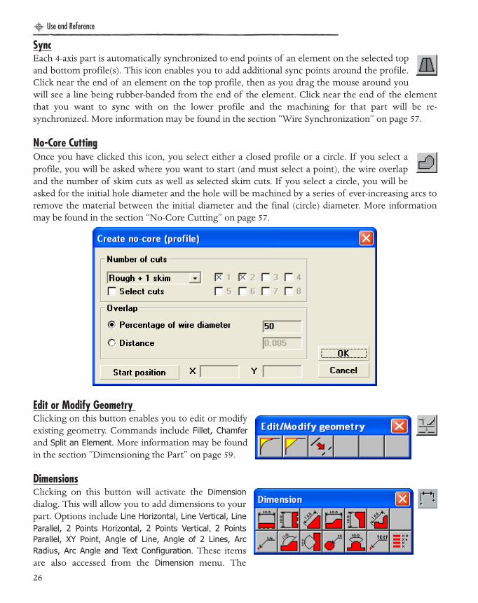
SyncEach 4-axis part is automatically synchronized to end points of an element on the selected topand bottom profile(s). This icon enables you to add additional sync points around the profile.Click near the end of an element on the top profile, then as you drag the mouse around youwill see a line being rubber-banded from the end of the element. Click near the end of the elementthat you want to sync with on the lower profile and the machining for that part will be re-synchronized. More information may be found in the section “Wire Synchronization” on page 57.
No-Core CuttingOnce you have clicked this icon, you select either a closed profile or a circle. If you select aprofile, you will be asked where you want to start (and must select a point), the wire overlapand the number of skim cuts as well as selected skim cuts. If you select a circle, you will beasked for the initial hole diameter and the hole will be machined by a series of ever-increasing arcs toremove the material between the initial diameter and the final (circle) diameter. More informationmay be found in the section “No-Core Cutting” on page 57.
Edit or Modify Geometry Clicking on this button enables you to edit or modifyexisting geometry. Commands include Fillet, Chamferand Split an Element. More information may be foundin the section “Dimensioning the Part” on page 59.
DimensionsClicking on this button will activate the Dimensiondialog. This will allow you to add dimensions to yourpart. Options include Line Horizontal, Line Vertical, LineParallel, 2 Points Horizontal, 2 Points Vertical, 2 PointsParallel, XY Point, Angle of Line, Angle of 2 Lines, ArcRadius, Arc Angle and Text Configuration. These itemsare also accessed from the Dimension menu. The
26
Use and Reference
EDM Manual.book Page 27 Wednesday, May 31, 2006 1:14 PM
descriptions of each item are under “Dimension Menu” on page 13 and more details on dimensioninga part may be found in the section “Dimensioning the Part” on page 59.
Information Clicking on this button will activate the Info dialog. The Infodialog has several utilities. Commands include Any ConstructionElement, Any Non-construction Element, Measure, Area/Perimeterand Calculator. Select an element to get data relating to its startpoint, end point, angle etc. More information may be found inthe section “Information” on page 60.
Resequence the Operations Resequence the order of machining. The machining isnormally carried out in the order in which you have created it.To change this sequence, click on this icon and simply selecteach part or No-Core shape/circle that you want to machinein the order that you want to cut them. If you only select someparts, then those selected will be machined before the othersthat were not selected. Note that all No-Core cuts will alwaysbe performed before the parts are cut. More information maybe found in the section “Resequence the Operations” on page 62.
27

Use and Reference
EDM Manual.book Page 28 Wednesday, May 31, 2006 1:14 PM
Operation Sheet Clicking on this button generates an Operation sheet that includes part notes, a listing of alloperations and a part preview. The content may be customized by selecting the Notes itemfrom the File menu. The data entered in Notes will be reflected in the Operations sheet.
28
Use and Reference
EDM Manual.book Page 29 Wednesday, May 31, 2006 1:14 PM
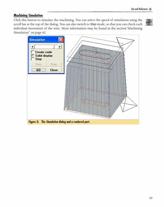
Machining Simulation Click this button to simulate the machining. You can select the speed of simulation using thescroll bar at the top of the dialog. You can also switch to Step mode, so that you can check eachindividual movement of the wire. More information may be found in the section“MachiningSimulation” on page 62
Figure 3: The Simulation dialog and a rendered part.
29

Use and Reference
EDM Manual.book Page 30 Wednesday, May 31, 2006 1:14 PM
Create CNC code Clicking this button will allow you to simultaneously generate the CNC code and view the CutPart Rendering. When Go is clicked, you will be prompted to enter a program number. Whenyou click OK after entering a program number, the rendering and code generation will begin.The code is saved to the file “W1” on your C:\ drive by default. More information may be found in thesection“Creating CNC Code” on page 63.
Figure 4: Dialogs involved in creating code.
30

Use and Reference
EDM Manual.book Page 31 Wednesday, May 31, 2006 1:14 PM
USING THE PACKAGE - DETAILWIRE CONFIGURATION/STRATEGYThe Wire Strategy/Configuration Settings dialog is split into three areas, each selected by clickingon the relevant tab near the top of the dialog.
Wire Configuration - Machine Configuration TabThe settings found in the Machine configuration tab enable you to set the parameters for the machinethat will be used to cut the part.
31
Use and Reference
EDM Manual.book Page 32 Wednesday, May 31, 2006 1:14 PM
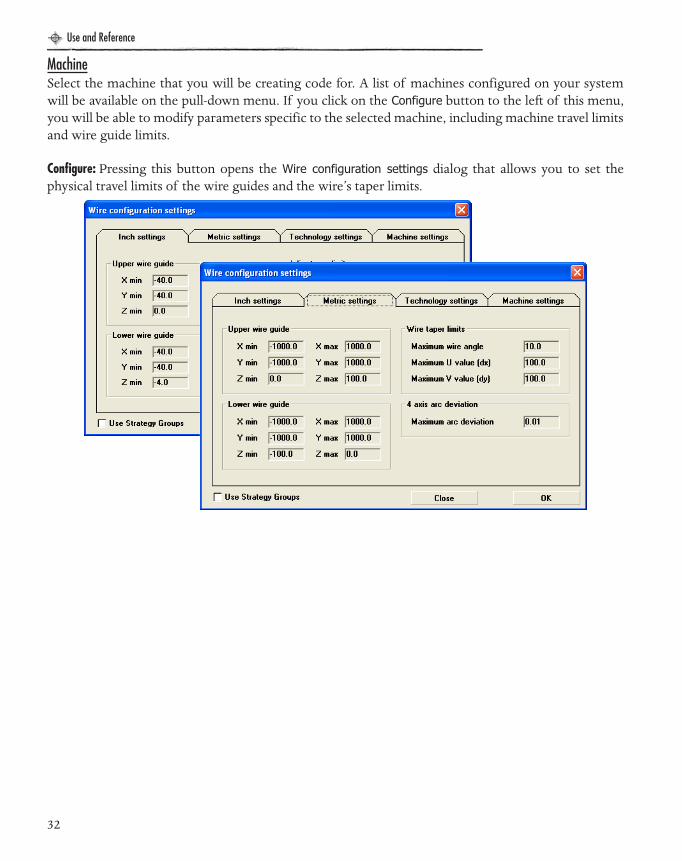
MachineSelect the machine that you will be creating code for. A list of machines configured on your systemwill be available on the pull-down menu. If you click on the Configure button to the left of this menu,you will be able to modify parameters specific to the selected machine, including machine travel limitsand wire guide limits.
Configure: Pressing this button opens the Wire configuration settings dialog that allows you to set thephysical travel limits of the wire guides and the wire’s taper limits.
32
Use and Reference
EDM Manual.book Page 33 Wednesday, May 31, 2006 1:14 PM
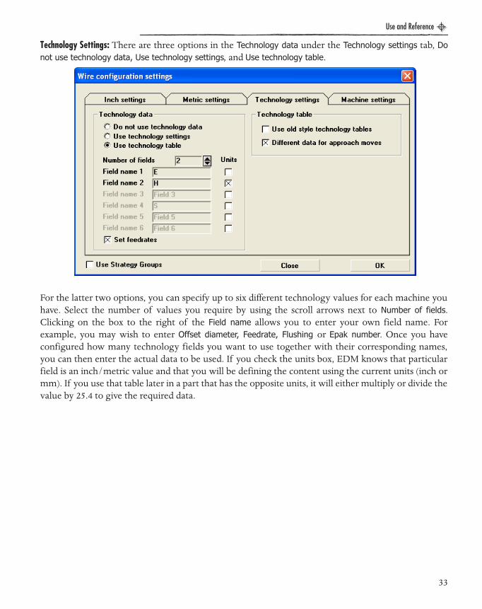
Technology Settings: There are three options in the Technology data under the Technology settings tab, Donot use technology data, Use technology settings, and Use technology table.
For the latter two options, you can specify up to six different technology values for each machine youhave. Select the number of values you require by using the scroll arrows next to Number of fields.Clicking on the box to the right of the Field name allows you to enter your own field name. Forexample, you may wish to enter Offset diameter, Feedrate, Flushing or Epak number. Once you haveconfigured how many technology fields you want to use together with their corresponding names,you can then enter the actual data to be used. If you check the units box, EDM knows that particularfield is an inch/metric value and that you will be defining the content using the current units (inch ormm). If you use that table later in a part that has the opposite units, it will either multiply or divide thevalue by 25.4 to give the required data.
33

Use and Reference
EDM Manual.book Page 34 Wednesday, May 31, 2006 1:14 PM
When employing the Use technology settings option, this is done by clicking on the Technology settingsbutton under the Machine section in the Wire strategy/configuration settings dialog.
The above table enables you to provide values for each technology field against each wire number thatyou will use to machine the parts. You can specify up to eight different wire numbers, one roughingand seven skim. The values entered in this table will be available next time you start the system;alternatively, you can save specific sets of data and reload them later and therefore build up a library oftechnology data for different material types, thicknesses, etc.
When Use technology table is selected, click the Technology table button under the machine section inthe Wire strategy/configuration settings dialog to define the technology table using the dialog shownabove.
A technology table contains a number of pre-defined machining methods which indicate how manyskim cuts are to be used and the settings associated with the rough and each individual skim cut. Inthe example shown above, we have selected Rough + 1 Skim and entered data for these two cuts. Oncethe technology table is defined, click Save table to save it for future use.
Set Feedrates: Set Feedrates checkbox at the bottom of the Technology Settings dialog enables the input offeedrates against each wire offset. If this checkbox is enabled, the Machining Report button at thebottom of the Wire strategy/configuration settings dialog becomes active. The Machining Report is alsodiscussed on page 39.
34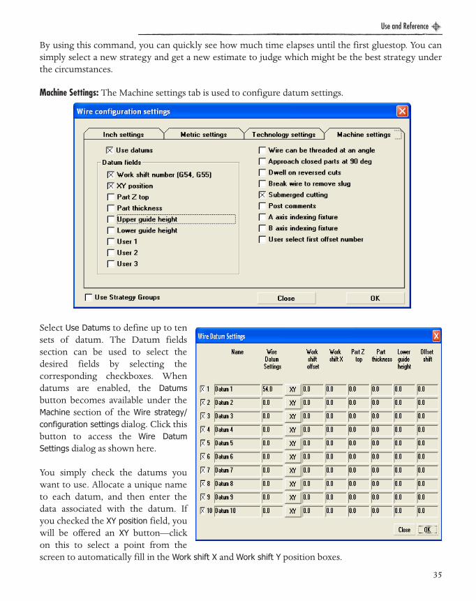
Use and Reference
EDM Manual.book Page 35 Wednesday, May 31, 2006 1:14 PM
By using this command, you can quickly see how much time elapses until the first gluestop. You cansimply select a new strategy and get a new estimate to judge which might be the best strategy underthe circumstances.
Machine Settings: The Machine settings tab is used to configure datum settings.
Select Use Datums to define up to tensets of datum. The Datum fieldssection can be used to select thedesired fields by selecting thecorresponding checkboxes. Whendatums are enabled, the Datumsbutton becomes available under theMachine section of the Wire strategy/configuration settings dialog. Click thisbutton to access the Wire DatumSettings dialog as shown here.
You simply check the datums youwant to use. Allocate a unique nameto each datum, and then enter thedata associated with the datum. Ifyou checked the XY position field, youwill be offered an XY button—clickon this to select a point from thescreen to automatically fill in the Work shift X and Work shift Y position boxes.
35
Use and Reference
EDM Manual.book Page 36 Wednesday, May 31, 2006 1:14 PM
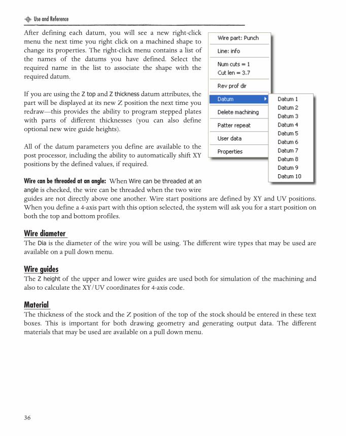
After defining each datum, you will see a new right-clickmenu the next time you right click on a machined shape tochange its properties. The right-click menu contains a list ofthe names of the datums you have defined. Select therequired name in the list to associate the shape with therequired datum.
If you are using the Z top and Z thickness datum attributes, thepart will be displayed at its new Z position the next time youredraw—this provides the ability to program stepped plateswith parts of different thicknesses (you can also defineoptional new wire guide heights).
All of the datum parameters you define are available to thepost processor, including the ability to automatically shift XYpositions by the defined values, if required.
Wire can be threaded at an angle: When Wire can be threaded at anangle is checked, the wire can be threaded when the two wireguides are not directly above one another. Wire start positions are defined by XY and UV positions.When you define a 4-axis part with this option selected, the system will ask you for a start position onboth the top and bottom profiles.
Wire diameter The Dia is the diameter of the wire you will be using. The different wire types that may be used areavailable on a pull down menu.
Wire guidesThe Z height of the upper and lower wire guides are used both for simulation of the machining andalso to calculate the XY/UV coordinates for 4-axis code.
Material The thickness of the stock and the Z position of the top of the stock should be entered in these textboxes. This is important for both drawing geometry and generating output data. The differentmaterials that may be used are available on a pull down menu.
36

Use and Reference
EDM Manual.book Page 37 Wednesday, May 31, 2006 1:14 PM
Output Z Planes These entries are used when generating code. It is recommended that you click on the Same as top andbottom of material button to automatically set these values based on the material settings.
The system outputs code based on the Z height of XY data. If your part is on a block, a customarrangement or below the top of the table, you will need to enter the proper values manually.
Part Orientation Specify how the part is situated. Rendering will be modified to match your setup.
Check Travel Limits When Creating CodeIf this option is checked, you will get a warning message if you try to move outside the travel limitsyou set for your machine.
Figure 5: Output is done at the Z height of the XY data.
37

Use and Reference
EDM Manual.book Page 38 Wednesday, May 31, 2006 1:14 PM
Advanced SettingsThe Advance Settings button opens a dialog that contains additional strategy options for control overthree areas of machining, No-Core circles, Circular dies and the entry moves made on Rough cuts.
No-Core Circles - Skim cut entry positions : This option is similar to that for circular dies (below). The skimcut entry positions may be adjusted for No-Core operations on a circle.
Rough cut entry moves : This option offers the facility to select the type of entry move for the rough cutfor each shape. The line and arc option will require the input of an arc radius (which will be used forall entry moves).
When a line and arc entry is selected, the line will start at the wire thread position and end tangent tothe arc (to form a teardrop shape). If the wire start position is less than the arc radius from the shape,then the line cannot be tangential to the arc (as it will start inside the arc) - in such cases 90 degrees ofarc will always be used.
For parts with land, a line-arc will only be used for roughing the land, unless the skim taper optionshas been selected on the second page of wire strategy settings.
TIP
To get skim cut entry position evenly spaced, the following conditions must be met:• You must select the machining strategy to remove gluestops with the rough cut.
• The shape must be a circle (not a circular contour).
!
There is no gouge checking for any arc entry moves, the user must ensure that gluestops arenot placed such that the arc will cut through any other part of the shape. In cases where landparts have line-arc entries for both land and taper, the user must check that the two arc entriesdo not create any loose material which may fall from the part.
38
Use and Reference
EDM Manual.book Page 39 Wednesday, May 31, 2006 1:14 PM
Circular dies - Skim cut entry positions: When gluestops are removed with the roughing cut, dies will havethe slug removed before any skim cuts. For circular dies, we have added the option to adjust the entrymoves for each of these skim cuts such that each skim will start at a different position. The entriespositions will be equally divided around the circular shape, so for 3 skim cuts they will be 120 degreesapart, 4 skim cuts 90 degrees apart and so on.
Each skim cut will comprise 2 circular arcs (of equal length) and each skim cut will go past theprevious exit position. So for 3 skim cuts, each skim cut will comprise two 240 degree arcs (to cover360 degrees, plus 120 degrees to the next skim cut start position).
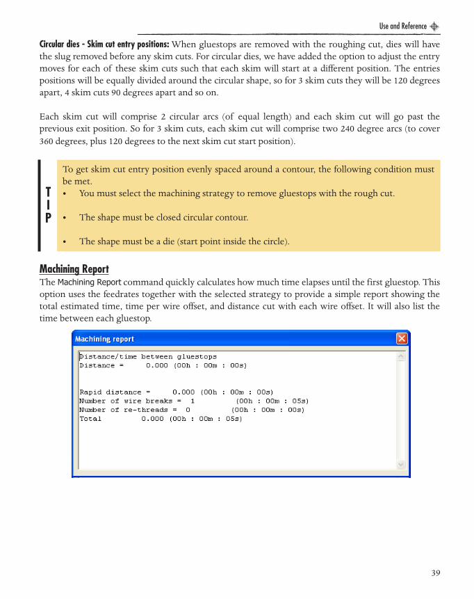
Machining ReportThe Machining Report command quickly calculates how much time elapses until the first gluestop. Thisoption uses the feedrates together with the selected strategy to provide a simple report showing thetotal estimated time, time per wire offset, and distance cut with each wire offset. It will also list thetime between each gluestop.
TIP
To get skim cut entry position evenly spaced around a contour, the following condition mustbe met.• You must select the machining strategy to remove gluestops with the rough cut.
• The shape must be closed circular contour.
• The shape must be a die (start point inside the circle).
39
Use and Reference
EDM Manual.book Page 40 Wednesday, May 31, 2006 1:14 PM
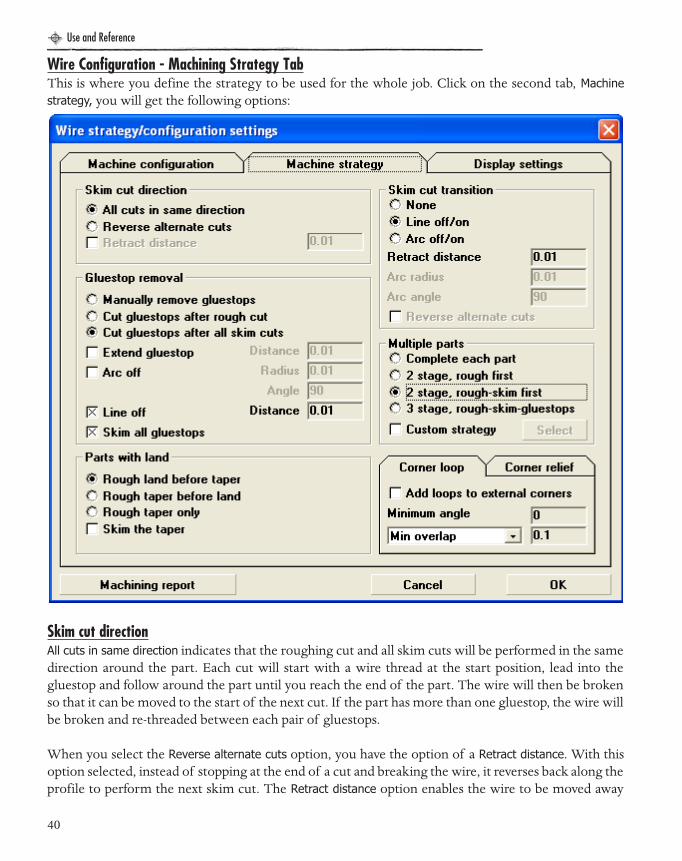
Wire Configuration - Machining Strategy TabThis is where you define the strategy to be used for the whole job. Click on the second tab, Machinestrategy, you will get the following options:
Skim cut directionAll cuts in same direction indicates that the roughing cut and all skim cuts will be performed in the samedirection around the part. Each cut will start with a wire thread at the start position, lead into thegluestop and follow around the part until you reach the end of the part. The wire will then be brokenso that it can be moved to the start of the next cut. If the part has more than one gluestop, the wire willbe broken and re-threaded between each pair of gluestops.
When you select the Reverse alternate cuts option, you have the option of a Retract distance. With thisoption selected, instead of stopping at the end of a cut and breaking the wire, it reverses back along theprofile to perform the next skim cut. The Retract distance option enables the wire to be moved away
40

Use and Reference
EDM Manual.book Page 41 Wednesday, May 31, 2006 1:14 PM
from the part (normal to the end of the element) so that a new offset can be selected. The wire is thenmoved back onto the part with the new offset before reversing back around the shape. Thus, for a partwith a single gluestop, the wire only needs to be broken once.
For multiple gluestops, the roughing cut and all skim cuts will be performed using alternately reversedcuts between each pair of gluestops. So, for a part with three gluestops, the part will be machined asfollows:
• All cuts will be performed between the first and second gluestop.
• Wire break, then re-threaded at start position for second gluestop.
• All cuts performed between second and third gluestop.
• Wire break, then re-threaded at start position for third gluestop.
• All cuts performed between third and first gluestop.
• Wire break.
Skim cut transitionWhen all skim cuts are performed in the same direction around the part, the wire offset needs to bechanged between each cut. This option provides for the wire to be moved away from the part in orderto change the offset before proceeding with the next cut. The move away can be either a straight lineor a tangential arc. When you select the Reverse alternate cuts instead of stopping at the end of a cutand breaking the wire, it reverses back along the profile to perform the next skim cut. The Retractdistance option enables the wire to be moved away from the part (normal to the end of the element) sothat a new offset can be selected.
Gluestop Removal: There are three options in this area. The first, Manually remove gluestops, simply means that all of thegluestops will be left in place. This option is useful when parts are held in with small micro-joints, sothat the parts do not fall out and the job can be run unmanned.
With the Cut gluestops after rough cut option, the wire will stop at each gluestop (ready for theoperator to clamp the part), then continue to remove the gluestop, with the final gluestop on the part
TIP
Please note that transitions on tapered or 4-axis parts can only be made by a line. Arcs are only available for parallel cuts.
41

Use and Reference
EDM Manual.book Page 42 Wednesday, May 31, 2006 1:14 PM
being extended by an optional extend distance. The wire will either be left in position on the part atthe end of the gluestop, or an optional arc away from the part can be added.
With the Cut gluestops after all skim cuts option, each cut will leave the gluestops in place. Only whenthe final skim cut has been performed will the gluestops be removed. When you select this optionwith the Complete each part wire strategy, the rough and skim cuts are treated as one set of cuts whenpairing the cuts together (the wire is reversed after the rough cut, avoiding the need to break and re-thread). If you check the Skim all gluestops box, then the gluestop will be cut with the same number ofskim cuts as the part; otherwise, it will be removed by a single roughing cut.
Multiple Parts: The Complete each part option indicates that each part must be roughed, skimmed and the gluestopsremoved before moving onto the next part. 2 Stage, Rough first roughs all parts, then goes back to eachpart for a second stage of skim cuts and gluestop removal before proceeding to the next part. 2 Stage,Rough-skim first roughs and skims each part, and then goes back to each part for a second stage of cutsconsisting of the removal of gluestops. 3 stage, rough-skim-gluestops roughs each part skims each part,and then removes the glues stops from each part.
Selecting the Custom Strategy checkbox will enable the Select button. Click this button to define yourindividual strategy for machining multiple parts using the dialog shown below.
TIP
If you use this option, since all of the gluestops will be removed beforeany skim cuts, the reverse skim cuts option will be ignored. There is noneed to reverse cuts—all skim cuts will follow the same direction.
42

Use and Reference
EDM Manual.book Page 43 Wednesday, May 31, 2006 1:14 PM
You will see a list of each operation type (rough, skim, gluestops) which is further divided by part type(parallel, tapered, etc.). Deselect Treat open and closed profiles the same or the Treat punches and dies thesame checkbox to get an extended list where parts are further subdivided into open and closed shapesas shown.
There are also three options available for removal of gluestops. They are Cut gluestops after all skimcuts, Cut gluestops after all rough cuts and Manually remove gluestops for Open profiles, Dies or Punches.These gluestop options are fully discussed on page 41.
A custom strategy defines how to machine multiple parts using up to eight separate passes across theentire machining process. All of the operations to be undertaken for the first pass will be listed in thefirst (left-hand) box. To move an operation to the next pass, simply click on it to highlight it, then pressthe left or right arrow key to move it to the previous or following passes.There are four defined passes
43

Use and Reference
EDM Manual.book Page 44 Wednesday, May 31, 2006 1:14 PM
in this example. there will be four operations on the first pass, two on the second, only a parallel skimcut on the third and so forth.
You can save or load your custom strategies for use on other jobs by using the buttons at the bottomof the dialog.
Parts with Land: This set of radio buttons define how land may be handled. The options include roughing the landbefore the taper, roughing the taper first or roughing the taper only (ignoring the land). Check Skimthe taper to skim both the land and the taper for parts with land, and uncheck this option to skim theland only.
Corner Loop and Corner Relief: These two mini-tabs enable automatic corner looping and corner relief moves. They both work insimilar fashion and you can choose to use either, both, or neither of the options. Corner looping andcorner Relief is available for nocore parts as well.
44

Use and Reference
EDM Manual.book Page 45 Wednesday, May 31, 2006 1:14 PM
When Add loops to external corners is enabled, all parallel cuts (including the land on parts with land)will have corner loops automatically added to external corners (including external corners inside dies).A loop will be added by extending the two elements by at least the distance specified (which can be amultiple of the wire diameter or a specific value, selected by using the pull-down menu). Havingextended the elements, a tangential arc will be added from the end of the first element to the start ofthe second. Note that the radius of the loop will be automatically calculated and will be larger forsharper corners. The Minimum angle setting is used to enter the smallest change in angles betweenelements before a loop is added.
Three options are offered for corner relief: Do not relieve internal corners, Add loops to internal corners,and Add lines to internal corners. Loops are added by moving back along each element by the specifieddistance (again, either a multiple of the wire diameter or a specific value) and adding an arc whosecenter is located at the original corner position. Lines are added at the corner itself, one away from thecorner and another back along the same path to return to the corner. These lines will follow a paththat bisects the angle of the corner; the length of each move is the distance specified (same as loopradius).
Wire Configuration - Display Settings Tab:The third tab in this dialog provides some control on how the parts are drawn.
45

Use and Reference
EDM Manual.book Page 46 Wednesday, May 31, 2006 1:14 PM
Display Settings:Since each skim cut follows the same path as the first roughing cut, if they were all drawn on top ofeach other, you would have no idea how many cuts had been programmed. Therefore, each skim cutis displayed above the previous cut, with the Z distance between each skim cut being set on this form.
Four-axis parts are drawn with a series of lines between the top and bottom profile to indicate how thetwo profiles are joined together and synchronized. The distance between these 4-axis lines is also seton this form using Distance between 4 axis display lines.
Show / Hide:You can optionally switch off the display of skim cuts, 4-axis lines and sync lines that have beeninteractively added to 4-axis parts. By pressing the button to the left of the colored boxes, you are alsoable to change the colors used to display the lines used for 4-axis display. This is particularly useful fordifferentiating between system-defined syncs and user-defined syncs.
Wire guide display:Choose your preferences for the Wire guide display; you may prefer to display them as Rendered (small),or Rendered (large).
Extend wire through guides is used to provide a more realistic simulation. The wire will be drawnthrough and past the guides.
Simulation Speed:Adjust the Simulation speed during rendering using the slide control in this section.
Viewport Selection:Under Viewport selection, choose Mouse click to select a particular viewport by moving the mouse overthe view and clicking on it. Choose Mouse over to automatically select the view that the mouse is over.
Display datums:Under the Display datums section, you have the option of displaying datum symbols at the XY positiondefined together with the name of any datum associated with a particular shape.
TIP
Mouse over makes it much faster to move between views and to use the mouse zoom and/or pan to get the display you want. However, should you wish to change a particular view (say, plan view to side view), make sure that you move the mouse out of the view and up to the icon to select the new view at the top of the screen without going through another view (since you will simply select a new view as the mouse moves over it). If this is something that you do more often, you may prefer to select Mouse click instead of Mouse over.
46

Use and Reference
EDM Manual.book Page 47 Wednesday, May 31, 2006 1:14 PM
AGIE MACHINESThis version includes Agie Evolution, Excellence and Progress post processors. When one of theseposts are selected, a new button, ‘AgieCut Settings,’ will be available on the first page of Wire Strategy/Configuration Settings.
The Agie post processorsrequire the selection ofMaterial type, Wire type andMachining quality. Thisselection is displayed byclicking the ‘Agie Settings’button which opens the newinput form shown on the right.
Quality: The surface quality of awhole workpiece.The qualityof machining is done by thesefive parameters.
Ra: Roughness.
Te: Corner precision.
Tkm: Tolerance of form.
Speed high: Priority for speed.
Quality high: Priority for high quality.
47
Use and Reference
EDM Manual.book Page 48 Wednesday, May 31, 2006 1:14 PM
Output Taper Parts As: There are two different taper modes:
Agie Standard Conic: Taper value is constant on the whole contour (cylindrical).
4 Axis Geometry: The standard 4 axis taper (non-cylindrical).
Material: Material of the pieces that are defined in a technological database. The default material is“Cold die Steel.”
Wire: Wires are defined in a technological database insie the AGIEVISION. The default wire is “CobraCut A 0.25.”
Entry / Exit Start Holes / Minimum Dia (num): The minimum diameter of all Entry and Exit Start Holes.
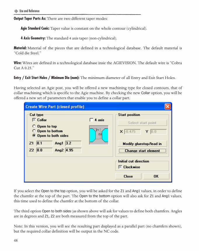
Having selected an Agie post, you will be offered a new machining type for closed contours, that ofcollar machining which is specific to the Agie machine. By checking the new Collar option, you will beoffered a new set of parameters that enable you to define a collar part.
If you select the Open to the top option, you will be asked for the Z1 and Ang1 values, in order to definethe chamfer at the top of the part. The Open to the bottom option will also ask for Z1 and Ang1 values,this time used to define the chamfer at the bottom of the collar.
The third option Open to both sides (as shown above will ask for values to define both chamfers. Anglesare in degrees and Z1, Z2 are both measured from the top of the part.
Note: In this version, you will see the resulting part displayed as a parallel part (no chamfers shown),but the required collar definition will be output in the NC code.
48

Use and Reference
EDM Manual.book Page 49 Wednesday, May 31, 2006 1:14 PM
AGIE OUTPUTWhen you create code using an Agie post processor, the NC output filename you select is used as thebasis for all of the output files created.
For example, if you provide a filename of c: \Evolution\ABC, the following files will be created (all inthe c:\ABC folder):
Note: In this version, you will see the resulting part displayed as a parallel part (no chamfers shown),but the required collar definition will be output in the NC code.
ABC.SBR and ABC.SBL The job files
For each part (contour) you will get 2 files
ABCn.ISO and ABCn.ISR Geometry files
Where n is the part number (1 for the first part, 2 for second and so on).
For each no-core part you will get 4 files:
ABCnr.ISO and ABCnr.ISR Geometry files for roughing
ABCns.ISO and ABCns ISR Geometry files for skim cuts
For example, for a job with 2 parts and 1 no-core circle, you will get the following files (for the inputfilename ABC):
ABC.SBR and ABC.SBL Job files
ABC1.ISO and ABC1.ISR Part 1 (contour)
ABC2r.ISO and ABC2r.ISR Part 2 (no-core roughing)
ABC2sISO and ABC2s ISR Part 2 (no-core skim)
!
Since the Agie post processor expects filenames to be no more than 8 characters, you must ensure that the filename you specify is no more than 5 characters (files are numbered, so if you have more than 10 parts, you must only use 4 characters.). You must also make certain that you do not add any suffix to a filename.
49

Use and Reference
EDM Manual.book Page 50 Wednesday, May 31, 2006 1:14 PM
The Agie post processorsrequire the selection ofMaterial type, Wire type andMachining quality. Thisselection is displayed byclicking the ‘Agie Settings’button which opens the newinput form shown on the right.
Quality: The surface quality of awhole workpiece.The qualityof machining is done by thesefive parameters.
Ra: Roughness.
Te: Corner precision.
Tkm: Tolerance of form.
Speed high: Priority for speed.
Quality high: Priority for high quality.
Output Taper Parts As: There are two different taper modes:
50

Use and Reference
EDM Manual.book Page 51 Wednesday, May 31, 2006 1:14 PM
CHARMILLES CT MACHINESWhen this post is selected a ‘CT’ icon will appear in the toolbar, this opens ‘CT Expert.’ A ‘CTExpert Settings’ button also will appear on the first page of Wire Strategy Settings.
Charmille Machine, Wire andPart information, also SequenceDefinition are displayed byclicking the ‘CT Expert Setting’button which opens the formshown below.
Configure CT Expert Interface: Showor change where the ‘CTExpert’ Files are kept .
Get data from CT Expert: Get datafrom ‘CT Expert’ such as wiretype and/or diameter,workpiece material and heightand the desired surface finish.
Apply these CT Expert settings:Applies new data from ‘CTExpert’ to the currentapplication.
51

Use and Reference
EDM Manual.book Page 52 Wednesday, May 31, 2006 1:14 PM
CREATING A WIRE EDM PARTWhen you click on this icon and select a profile, you will be presented with the followingoptions to describe how the part is to be machined.
The first thing you must do is to select a start point. Click on the Select start point button and select apoint that represents where the wire is to be threaded, prior to leading into the start of the part.
If the shape is closed, then the first element to be machined on the part will be the element youselected when you picked the profile. The lead-in will be created normal to this element, starting atthe selected point. If the shape is an open profile, you have the option of starting at the start of the firstelement in the profile, or starting away from the profile (you will need to select a start point).
TIP
If you choose to start on the profile, then you can add entry/exit moves (to apply/cancel compensation) which will take the form of straight line moves either tangential to the profile, or at 90 degrees. You can also opt to extend the start/end of the end elements. If you select a gluestop, this will always be added at the end of the profile (before any extension is added).
52

Use and Reference
EDM Manual.book Page 53 Wednesday, May 31, 2006 1:14 PM
Having selected your start point, you mustthen specify the gluestop width. This is donein the Gluestop lead in/out dialog, shown below.This opens once a point is selected.
You can also enter the diameter of the starthole. This value will be available to the postprocessor in the event that you would like theapproach move split in accordance with thisdiameter so that you might use different Epaksettings for approaching the edge of the holeand approaching the part itself. If you select a circle for the start hole, the circle diameter willautomatically be used for the start hole diameter. The start point coordinates are displayed forinformational purposes only. These values can only be changed by pressing the Start point button andselecting a new point.
Once you press OK you will be returned to the previous form tospecify how the part is to be cut. You will see that the form haschanged slightly, so that you can modify this start gluestop.
The Modify gluestop/lead in button is now enabled, and clicking itwill bring back the Gluestop lead in/out dialog to enable you tochange either the start position, start hole diameter, or thegluestop width.
The Change start element button is also enabled. Clicking here willallow you to select a different element at which to start. This isuseful if you picked the wrong element on the profile and would like to start somewhere else on thepart.
Having selected your start point, it is a goodidea to select the Number of cuts. You have theoption of selecting between one and eight.Simply click on the required number at thebottom of the form. Note that this numberincludes the first roughing cut so, for example,four cuts would equal one roughing and three skim cuts. You may also select which specific wireoffsets to use simply by checking the appropriate boxes under Select cuts.
53

Use and Reference
EDM Manual.book Page 54 Wednesday, May 31, 2006 1:14 PM
Having selected the start element on the upper profile, EDM automatically projects an entry line fromthe start point to the start element and calculates which element on the lower profile this lineintersects—this is the default start point on the lower profile. Once you have selected the lower profile
Cut type: The Parallel cut option needs nofurther data. The wire is simply kept verticalto produce parallel walls. Selecting Full heighttaper requires a Taper angle (in degrees). Thepart will always be assumed to be larger at thebottom than at the top, so if this is not thecase, you will need to enter a negative angle.
You can change the angle of individualelements of a 2-axis tapered part using theTaper icon. This is the fourth item in the leftcolumn of the Top Level palette and is described on page 25 and under “Modify Taper Angle” onpage 56.
Adding land to a part requires the Land heightto be specified. A part with land will be cutonce with a roughing offset at the taper angle,then roughed and skimmed with parallel cutsto machine the land.
Near the top right-hand side of this section is acheckbox to indicate if this is to be a 4 axispart; checking this will change your options toinclude Full 4 axis and 4 axis with land.
Regardless of whether you choose Full 4 axis or4 axis with land, you must select a secondprofile to represent the bottom of the part. Todo this, click on the Select lower profile buttonand then pick the required profile, makingsure that the element you select on the profileis the first element to be machined. If you do not select the correct element, the part will appeartwisted—this can be corrected later, but it is better to get it correct now.
54
Use and Reference
EDM Manual.book Page 55 Wednesday, May 31, 2006 1:14 PM
of a 4-axis shape, click on Select start point on lower profile to select a different element at which to starton the lower profile.
The 4 axis with land option requires a Land height and is treated in similar fashion as 2-axis with land.The 4-axis cuts will be performed once, with a roughing offset, followed by one roughing and all skimcuts parallel to the top profile.
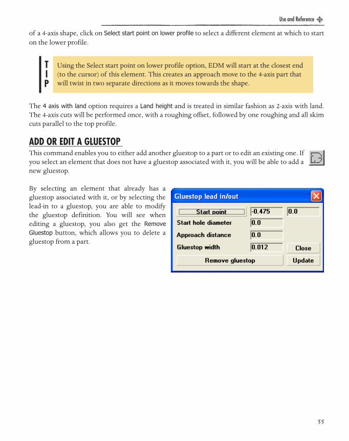
ADD OR EDIT A GLUESTOP This command enables you to either add another gluestop to a part or to edit an existing one. Ifyou select an element that does not have a gluestop associated with it, you will be able to add anew gluestop.
By selecting an element that already has agluestop associated with it, or by selecting thelead-in to a gluestop, you are able to modifythe gluestop definition. You will see whenediting a gluestop, you also get the RemoveGluestop button, which allows you to delete agluestop from a part.
TIP
Using the Select start point on lower profile option, EDM will start at the closest end (to the cursor) of this element. This creates an approach move to the 4-axis part that will twist in two separate directions as it moves towards the shape.
55

Use and Reference
EDM Manual.book Page 56 Wednesday, May 31, 2006 1:14 PM
MODIFY TAPER ANGLEBy selecting this icon, you can then select anelement or multiple elements of a 2-axistapered part for which you can modify thetaper angles.
Select the element you wish to modify to getthis form.
To modify a single element, enter the value ofthe New taper angle and click OK. To modifymultiple elements, click Select final elementand select the element at the other end of therange of elements; the number of selectedelements will be indicated in the boxunderneath this button. Clicking OK willupdate all the elements in the range with thenew taper angle.
Different start and end angles can be specifiedunder the Variable taper tab. Since this can only beapplied to one element at a time, the Range ofelements option is not provided in this case.
56

Use and Reference
EDM Manual.book Page 57 Wednesday, May 31, 2006 1:14 PM
WIRE SYNCHRONIZATIONThis icon enables you to add a sync line to a 4-axis part. Sync lines are added between the endsof elements on the two profiles that represent the top and bottom of the part. First, select theelement on the top profile, picking near to the end where the synchronization is to occur, thenclick on the corresponding element on the bottom profile.
If you require the wire toremain stopped on oneprofile, while it continues onthe other profile (e.g. stoppedon the top and move arounda radius on the bottom), thenyou may add two sync linesto the same element on the profile where the wire is to stop, each of these corresponding to a differentelement on the other profile. No point may have more than two syncs.
When a 4-axis part has the same number of elements on both the upper and lower profiles, you canright-click on the part and be offered the option to automatically synchronize the cut.
If you have already added user syncs, then this option will further auto-sync between each pair of usersyncs.
NO-CORE CUTTINGAfter selecting this icon, youwill be asked to select eithera profile or a circle. If youselect a profile, it must beclosed—you will then beable to cut all of the areawithin the profile by usingthe dialog shown here.Corner loop and CornerRelief is also available. Formore information see“Corner Loop and CornerRelief:” on page 44.
Number of cuts:You can add optional skimcuts around the profile shape by selecting a number from one to eight in the Number of skim cuts tab.You may also select which specific wire offsets to use under the Selected skim cuts tab.
57

Use and Reference
EDM Manual.book Page 58 Wednesday, May 31, 2006 1:14 PM
Overlap:The Overlap between cuts can be defined either by a percentage of wire diameter or by an actualdistance. If you select Percentage of wire diameter and then change the wire diameter in the wirestrategy control, the resulting destruction cuts will automatically be re-calculated based on the newwire size.
Click on the Start position button to select a start point where the wire will be threaded.
If you select a circle for No-Core cutting, then you willbe presented with thedialog shown. As for thecutting profile, you canspecify the Overlap as eithera distance or as apercentage of the wirediameter (automatic re-calculation also applies,should you change the wirediameter).
The start position will bedisplayed as the center ofthe selected circle and theFinal diameter is also takenfrom the selected circle. You can change the Initial diameter to be a value other than zero, in which casethe No-Core cutting will start at that specified diameter, rather than at the center of the circle.
Checking the CW box will create clockwise arcs, and leaving it unchecked will create counter-clockwise cuts.
58
Use and Reference
EDM Manual.book Page 59 Wednesday, May 31, 2006 1:14 PM
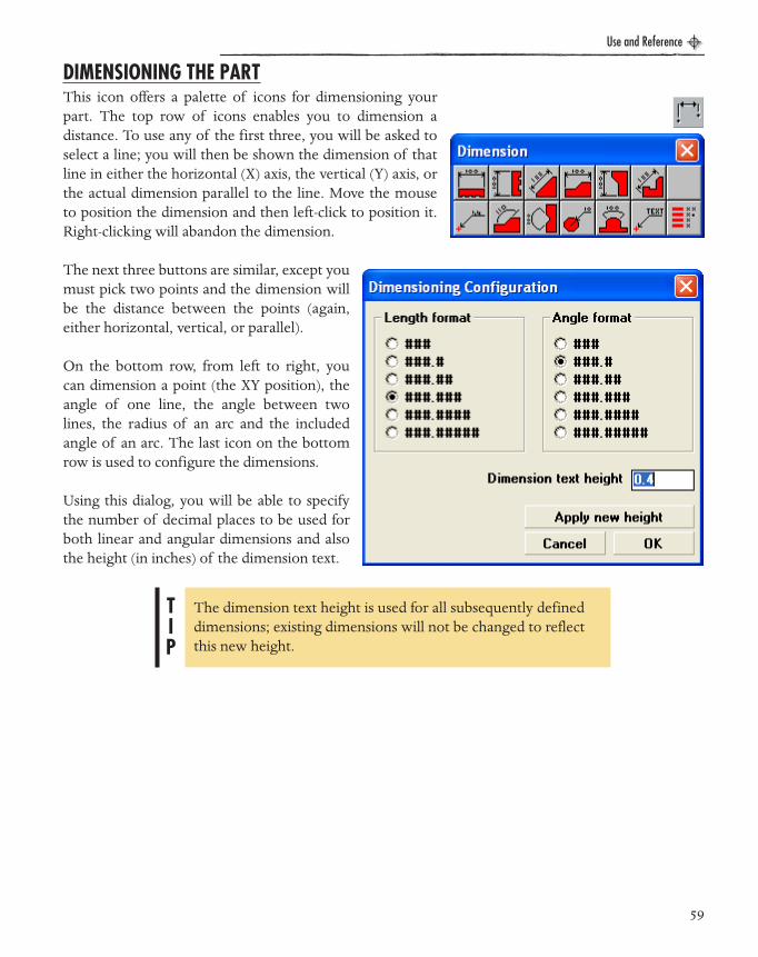
DIMENSIONING THE PARTThis icon offers a palette of icons for dimensioning yourpart. The top row of icons enables you to dimension adistance. To use any of the first three, you will be asked toselect a line; you will then be shown the dimension of thatline in either the horizontal (X) axis, the vertical (Y) axis, orthe actual dimension parallel to the line. Move the mouseto position the dimension and then left-click to position it.Right-clicking will abandon the dimension.
The next three buttons are similar, except youmust pick two points and the dimension willbe the distance between the points (again,either horizontal, vertical, or parallel).
On the bottom row, from left to right, youcan dimension a point (the XY position), theangle of one line, the angle between twolines, the radius of an arc and the includedangle of an arc. The last icon on the bottomrow is used to configure the dimensions.
Using this dialog, you will be able to specifythe number of decimal places to be used forboth linear and angular dimensions and alsothe height (in inches) of the dimension text.
TIP
The dimension text height is used for all subsequently defined dimensions; existing dimensions will not be changed to reflect this new height.
59

Use and Reference
EDM Manual.book Page 60 Wednesday, May 31, 2006 1:14 PM
INFORMATIONThis icon offers several methods of obtaining informationrelating to the part via the following palette of icons.
The first two icons provide information on a selected element.Use the first icon to select a construction element (point orcircle).
The second icon is for a profile line or arc. Click on the icon and then select the required element andyou will be shown information specific to the type of element selected. This may include start/endpoint, length, and angle.
The third icon is used to measure the distance between two points. After selecting the two points, youwill be shown the distance between them relative to the X axis and the Y axis as well as the actualdistance between them.
60
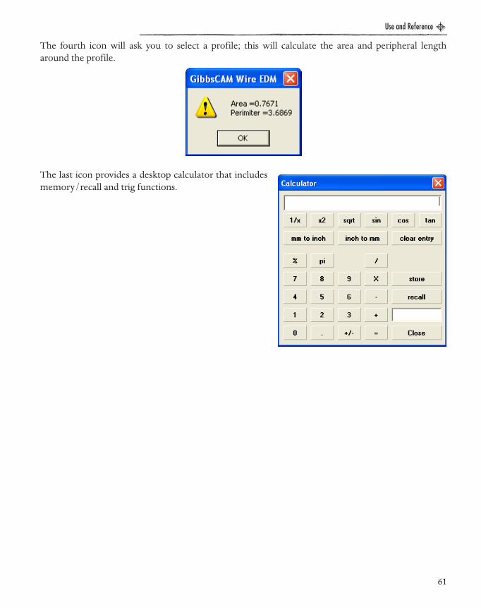
Use and Reference
EDM Manual.book Page 61 Wednesday, May 31, 2006 1:14 PM
The fourth icon will ask you to select a profile; this will calculate the area and peripheral lengtharound the profile.
The last icon provides a desktop calculator that includesmemory/recall and trig functions.
61
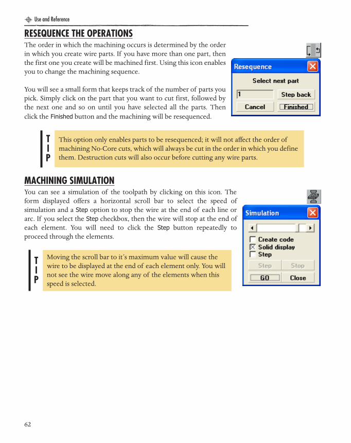
Use and Reference
EDM Manual.book Page 62 Wednesday, May 31, 2006 1:14 PM
RESEQUENCE THE OPERATIONSThe order in which the machining occurs is determined by the orderin which you create wire parts. If you have more than one part, thenthe first one you create will be machined first. Using this icon enablesyou to change the machining sequence.
You will see a small form that keeps track of the number of parts youpick. Simply click on the part that you want to cut first, followed bythe next one and so on until you have selected all the parts. Thenclick the Finished button and the machining will be resequenced.
MACHINING SIMULATIONYou can see a simulation of the toolpath by clicking on this icon. Theform displayed offers a horizontal scroll bar to select the speed ofsimulation and a Step option to stop the wire at the end of each line orarc. If you select the Step checkbox, then the wire will stop at the end ofeach element. You will need to click the Step button repeatedly toproceed through the elements.
TIP
This option only enables parts to be resequenced; it will not affect the order of machining No-Core cuts, which will always be cut in the order in which you define them. Destruction cuts will also occur before cutting any wire parts.
TIP
Moving the scroll bar to it’s maximum value will cause the wire to be displayed at the end of each element only. You will not see the wire move along any of the elements when this speed is selected.
62

Use and Reference
EDM Manual.book Page 63 Wednesday, May 31, 2006 1:14 PM
CREATING CNC CODEThis icon provides the same toolpath simulation as described above, but CNC code is createdas the machining is being simulated. You will see a list of post processors that you haveavailable and also a box containing the file name of the CNC code file. To select a new codefilename, simply double-click on the box containing the filename. As the simulation is displayed, youwill also see the code being created.
63
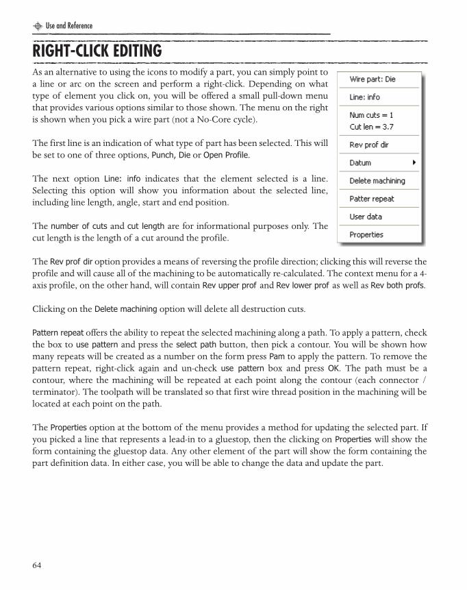
Use and Reference
EDM Manual.book Page 64 Wednesday, May 31, 2006 1:14 PM
RIGHT-CLICK EDITINGAs an alternative to using the icons to modify a part, you can simply point toa line or arc on the screen and perform a right-click. Depending on whattype of element you click on, you will be offered a small pull-down menuthat provides various options similar to those shown. The menu on the rightis shown when you pick a wire part (not a No-Core cycle).
The first line is an indication of what type of part has been selected. This willbe set to one of three options, Punch, Die or Open Profile.
The next option Line: info indicates that the element selected is a line.Selecting this option will show you information about the selected line,including line length, angle, start and end position.
The number of cuts and cut length are for informational purposes only. Thecut length is the length of a cut around the profile.
The Rev prof dir option provides a means of reversing the profile direction; clicking this will reverse theprofile and will cause all of the machining to be automatically re-calculated. The context menu for a 4-axis profile, on the other hand, will contain Rev upper prof and Rev lower prof as well as Rev both profs.
Clicking on the Delete machining option will delete all destruction cuts.
Pattern repeat offers the ability to repeat the selected machining along a path. To apply a pattern, checkthe box to use pattern and press the select path button, then pick a contour. You will be shown howmany repeats will be created as a number on the form press Pam to apply the pattern. To remove thepattern repeat, right-click again and un-check use pattern box and press OK. The path must be acontour, where the machining will be repeated at each point along the contour (each connector /terminator). The toolpath will be translated so that first wire thread position in the machining will belocated at each point on the path.
The Properties option at the bottom of the menu provides a method for updating the selected part. Ifyou picked a line that represents a lead-in to a gluestop, then the clicking on Properties will show theform containing the gluestop data. Any other element of the part will show the form containing thepart definition data. In either case, you will be able to change the data and update the part.
64

Use and Reference
EDM Manual.book Page 65 Wednesday, May 31, 2006 1:14 PM
If you right-click on part of a wire No-Core cycle, you will get a slightlydifferent menu.
The first line indicates whether you selected a circle or a profile. The thirdline provides access to element information. The cut length is the totalperipheral length of all the cuts used to destroy the circle /shape. Clicking onthe Delete machining option will delete all destruction cuts.
Clicking on the Properties option will show the form that was used to createthe cycle so that you can change the machining parameters.
Right-clicking on a 4-axis sync line provides a menu option to delete the syncline.
If you Right Click on a 4-axis line or arc or on a No-Core cycle, you will get themenu shown below.
If you have already addeduser syncs, then this optionwill further auto-syncbetween each pair of usersyncs.
If you right click on any othertype of element (a point, adimension, or a line/arc that has not been used to create a wire part), you will be presented with amenu that simply offers element information (in the case of a dimension, you can also delete theselected dimension).
Select the (Element): info option to bring up the Element info dialog asshown.
65

Use and Reference
EDM Manual.book Page 66 Wednesday, May 31, 2006 1:14 PM
POST PROCESSING ENHANCEMENTSA new post processor (‘drill.pp’) has been added to the library of posts. This will create a filecontaining only XY positions of the wire thread positions to be used to drill the material prior to useon the EDM machine.
A new document has been provided to help those wishing to modify or write their own postprocessors. This will include details on new post processing functionality added to this release:
• Simpler commands to format the output, thereby enabling easy switching between inch/metric and absolute/incremental output.
• Current single-line IF command enhanced to include IF/THEN blocks and IF/ELSE.• The ability to output part profile data (rather than toolpath data) as required by machines such as the Agie
Evolution.• Added flag in posts to indicate if part is upside-down.• Added new post variables for Part name, Part Filename, Tape Name, and variables for the new
datum functionality.
66
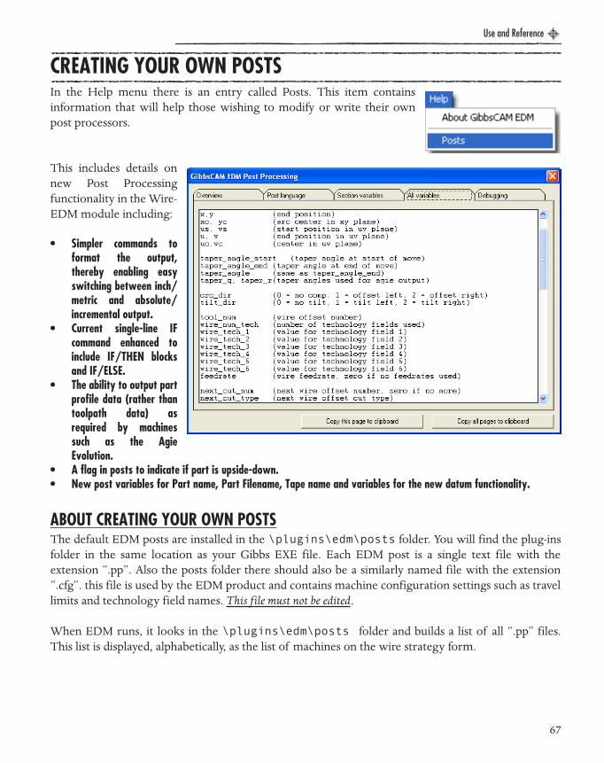
Use and Reference
EDM Manual.book Page 67 Wednesday, May 31, 2006 1:14 PM
CREATING YOUR OWN POSTS
ABOUT CREATING YOUR OWN POSTSThe default EDM posts are installed in the \plugins\edm\posts folder. You will find the plug-insfolder in the same location as your Gibbs EXE file. Each EDM post is a single text file with theextension “.pp”. Also the posts folder there should also be a similarly named file with the extension“.cfg”. this file is used by the EDM product and contains machine configuration settings such as travellimits and technology field names. This file must not be edited.
When EDM runs, it looks in the \plugins\edm\posts folder and builds a list of all “.pp” files.This list is displayed, alphabetically, as the list of machines on the wire strategy form.
In the Help menu there is an entry called Posts. This item containsinformation that will help those wishing to modify or write their ownpost processors.
This includes details onnew Post Processingfunctionality in the Wire-EDM module including:
• Simpler commands toformat the output,thereby enabling easyswitching between inch/metric and absolute/incremental output.
• Current single-line IFcommand enhanced toinclude IF/THEN blocksand IF/ELSE.
• The ability to output partprofile data (rather thantoolpath data) asrequired by machinessuch as the AgieEvolution.
• A flag in posts to indicate if part is upside-down.• New post variables for Part name, Part Filename, Tape name and variables for the new datum functionality.
67
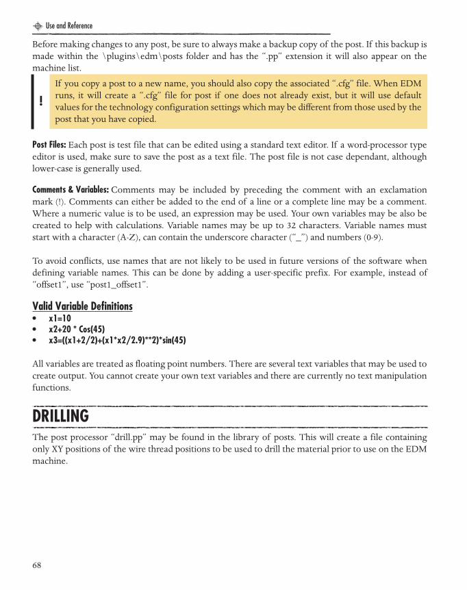
Use and Reference
EDM Manual.book Page 68 Wednesday, May 31, 2006 1:14 PM
Before making changes to any post, be sure to always make a backup copy of the post. If this backup ismade within the \plugins\edm\posts folder and has the “.pp” extension it will also appear on themachine list.
Post Files: Each post is test file that can be edited using a standard text editor. If a word-processor typeeditor is used, make sure to save the post as a text file. The post file is not case dependant, althoughlower-case is generally used.
Comments & Variables: Comments may be included by preceding the comment with an exclamationmark (!). Comments can either be added to the end of a line or a complete line may be a comment.Where a numeric value is to be used, an expression may be used. Your own variables may be also becreated to help with calculations. Variable names may be up to 32 characters. Variable names muststart with a character (A-Z), can contain the underscore character (“_”) and numbers (0-9).
To avoid conflicts, use names that are not likely to be used in future versions of the software whendefining variable names. This can be done by adding a user-specific prefix. For example, instead of“offset1”, use “post1_offset1”.
Valid Variable Definitions• x1=10• x2+20 * Cos(45)• x3=((x1+2/2)+(x1*x2/2.9)**2)*sin(45)
All variables are treated as floating point numbers. There are several text variables that may be used tocreate output. You cannot create your own text variables and there are currently no text manipulationfunctions.
DRILLINGThe post processor “drill.pp” may be found in the library of posts. This will create a file containingonly XY positions of the wire thread positions to be used to drill the material prior to use on the EDMmachine.
!
If you copy a post to a new name, you should also copy the associated “.cfg” file. When EDMruns, it will create a “.cfg” file for post if one does not already exist, but it will use defaultvalues for the technology configuration settings which may be different from those used by thepost that you have copied.
68
TUTORIALS
EDM Manual.book Page 69 Wednesday, May 31, 2006 1:14 PM

EDM Manual.book Page 70 Wednesday, May 31, 2006 1:14 PM

Tutorials
CHAPTER 3 : Tu t o r i a l s
EDM Manual.book Page 71 Wednesday, May 31, 2006 1:14 PM
The Tutorials section of the manual is designed to introduce you to actually working with theGibbsCAM Wire EDM package. There are three tutorials, one covering 2-axis parts, anothercovering 4-axis parts and the last covering open profile parts. All of the tutorials start with a part filethat came with your Wire EDM package. If you are unclear on a topic brought up in the tutorial,please refer to the Reference section of this manual.
TUTORIAL #1 WIRE EDM 2-AXIS
In this tutorial you will become familiar with working with the GibbsCAM Wire EDM interfaceand creating a simple 2-axis EDM part. You will need to have GibbsCAM and the Wire EDMpackage installed and licensed.
� Launch GibbsCAM.
� Open the file die block.vnc. The file should be located in a folder that was installed along with your Wire EDM package.
71
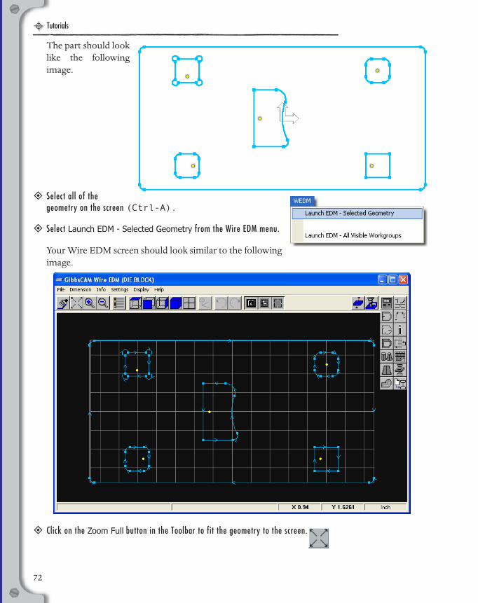
Tutorials
EDM Manual.book Page 72 Wednesday, May 31, 2006 1:14 PM
The part should looklike the followingimage.
� Select all of the geometry on the screen (Ctrl-A).
� Select Launch EDM - Selected Geometry from the Wire EDM menu.
Your Wire EDM screen should look similar to the followingimage.
� Click on the Zoom Full button in the Toolbar to fit the geometry to the screen.
72
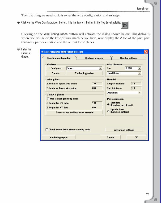
Tutorials
EDM Manual.book Page 73 Wednesday, May 31, 2006 1:14 PM
The first thing we need to do is to set the wire configuration and strategy.
� Click on the Wire Configuration button. It is the top left button in the Top Level palette.
Clicking on the Wire Configuration button will activate the dialog shown below. This dialog iswhere you will select the type of wire machine you have, wire display, the Z top of the part, partthickness, part orientation and the output for Z planes.
� Enter the values as shown.
73
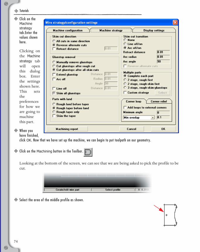
Tutorials
EDM Manual.book Page 74 Wednesday, May 31, 2006 1:14 PM
� Click on the Machine strategy tab.Enter the values shown here.
Clicking onthe Machinestrategy tabwill openthis dialogbox. Enterthe settingsshown here.This setsthepreferencesfor how weare going tomachinethis part.
� When you have finished, click OK. Now that we have set up the machine, we can begin to put toolpath on our geometry.
� Click on the Machining button in the Toolbar.
Looking at the bottom of the screen, we can see that we are being asked to pick the profile to becut.
� Select the area of the middle profile as shown.
74
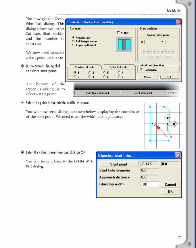
Tutorials
EDM Manual.book Page 75 Wednesday, May 31, 2006 1:14 PM
You now get the CreateWire Part dialog. Thisdialog allows you to setCut type, Start positionand the number ofskim cuts.
We now need to selecta start point for the cut.
� In the current dialog click on Select start point.
The bottom of thescreen is asking us toselect a start point.
� Select the point in the middle profile as shown.
You will now see a dialog, as shown below, displaying the coordinatesof the start point. We need to set the width of the gluestop.
� Enter the value shown here and click on OK.
You will be sent back to the Create WirePart dialog.
75

Tutorials
EDM Manual.book Page 76 Wednesday, May 31, 2006 1:14 PM
� Click OK.
� Click on the Isometric View button in the Toolbar.
� Click on the Zoom Full button in the Toolbar.
This will put the part into isometric view and fit the geometry and thetoolpath to the screen.The results of your toolpath should look likethe image on the right.
This is a simple example of how to create a wire path. Now we will goback and modify the toolpath.
� Right-click anywhere on the profile to open the right-click menu.
� Select Properties.
Clicking on Properties opens the Modify Wire Part dialog. This dialoglooks similar to the Create Wire Part dialog that we used to generate thetoolpath. We will use this dialog to modify the toolpath in order to seta taper and the number of skim cuts.
76

Tutorials
EDM Manual.book Page 77 Wednesday, May 31, 2006 1:14 PM
� Click on the Full height taper radio button.
This modifies the dialog to include a Taper angle text box and a different graphic.
� Enter a taper angle of 5 degrees.
Next we will add some skim cuts.
� In the Number of cuts section, click on 4 to set four skim cuts.
Your dialog should look like the image above.
� Click on Update.
The dialog should close and the result is anupdated toolpath that should look similar to theimage shown here.
The actual height between each displayed skimcut and the number as well as the color of thedashed 4-axis lines will vary depending on yourDisplay settings found in the Wire strategy/configuration settings dialog.
There is geometry on this part that was notcovered in this tutorial. You can use thisgeometry for continued practice with differentmachine settings, tapers etc.
77
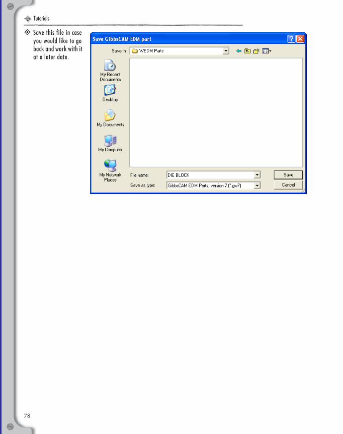
Tutorials
EDM Manual.book Page 78 Wednesday, May 31, 2006 1:14 PM
� Save this file in case you would like to go back and work with it at a later date.
78
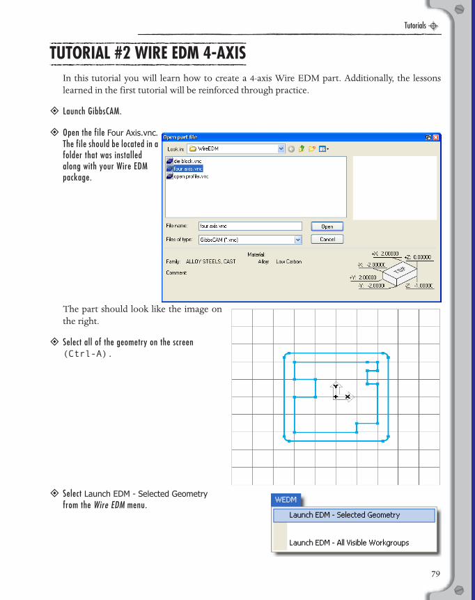
Tutorials
EDM Manual.book Page 79 Wednesday, May 31, 2006 1:14 PM
TUTORIAL #2 WIRE EDM 4-AXIS
In this tutorial you will learn how to create a 4-axis Wire EDM part. Additionally, the lessonslearned in the first tutorial will be reinforced through practice.
� Launch GibbsCAM.
� Open the file Four Axis.vnc. The file should be located in a folder that was installed along with your Wire EDM package.
The part should look like the image onthe right.
� Select all of the geometry on the screen (Ctrl-A).
� Select Launch EDM - Selected Geometry from the Wire EDM menu.
79
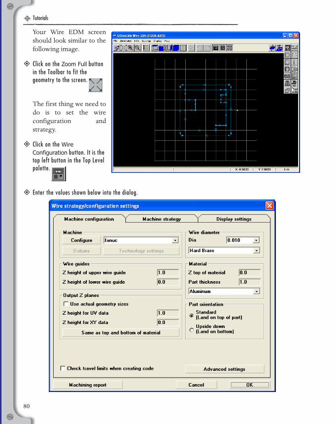
Tutorials
EDM Manual.book Page 80 Wednesday, May 31, 2006 1:14 PM
Your Wire EDM screenshould look similar to thefollowing image.
� Click on the Zoom Full button in the Toolbar to fit the geometry to the screen.
The first thing we need todo is to set the wireconfiguration andstrategy.
� Click on the Wire Configuration button. It is the top left button in the Top Level palette.
� Enter the values shown below into the dialog.
80

Tutorials
EDM Manual.book Page 81 Wednesday, May 31, 2006 1:14 PM
� Click on the Machine strategy tab and enter the settings shown here.
� When you have finished, click OK.
Now that we have set up the machine, we can begin to put a toolpath on our geometry.
� Click on the Machining button in the Top Level palette.
Looking at thebottom of thescreen, we can seethat we are beingasked to pick theprofile to be cut.
81
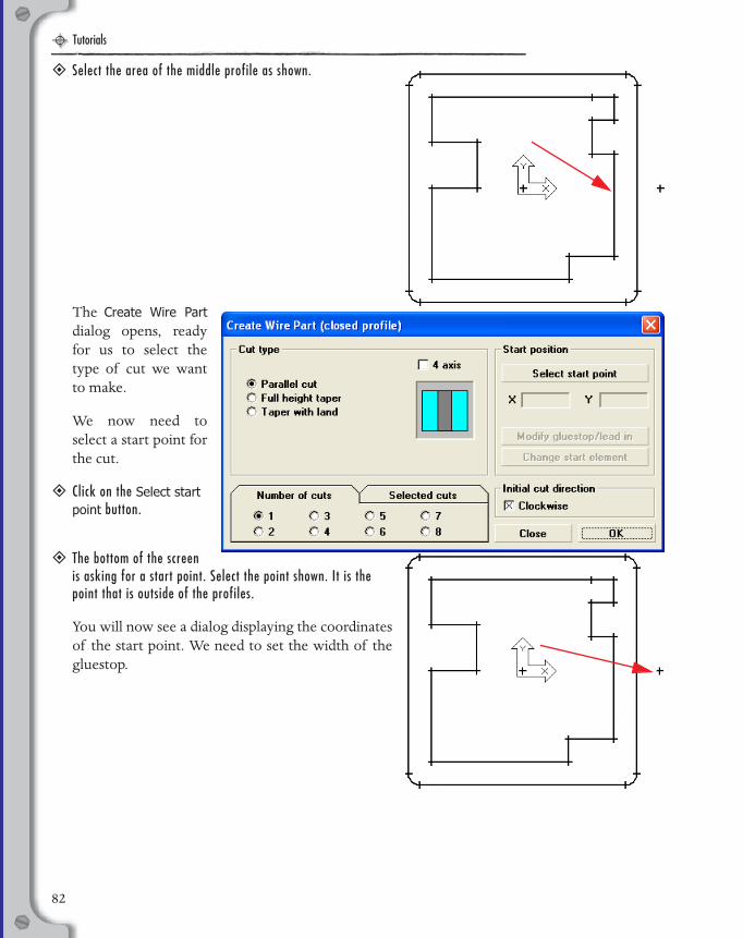
Tutorials
EDM Manual.book Page 82 Wednesday, May 31, 2006 1:14 PM
� Select the area of the middle profile as shown.
The Create Wire Partdialog opens, readyfor us to select thetype of cut we wantto make.
We now need toselect a start point forthe cut.
� Click on the Select start point button.
� The bottom of the screen is asking for a start point. Select the point shown. It is the point that is outside of the profiles.
You will now see a dialog displaying the coordinatesof the start point. We need to set the width of thegluestop.
82
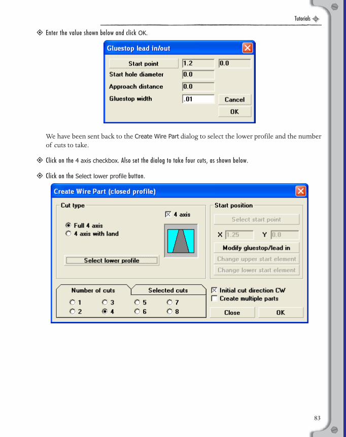
Tutorials
EDM Manual.book Page 83 Wednesday, May 31, 2006 1:14 PM
� Enter the value shown below and click OK.
We have been sent back to the Create Wire Part dialog to select the lower profile and the numberof cuts to take.
� Click on the 4 axis checkbox. Also set the dialog to take four cuts, as shown below.
� Click on the Select lower profile button.
83

Tutorials
EDM Manual.book Page 84 Wednesday, May 31, 2006 1:14 PM
� Select the profile as shown to designate the lower profile.
When you select the lower profile, we are sent backto the Create Wire Part dialog to finish setting up thetoolpath.
� Click OK.
The results of our workshould look something likethe following image.Looking at the toolpath, weprobably have some morework to do, as is often thecase with 4-axis parts. Weneed to synchronize the wirepath.
In order to sync this toolpath,we need to break some of theelements. To make thiseasier, we are first going toturn on the Command repeatoption.
� Click on the Configuration button in the Toolbar to open the Configuration dialog. It is the fifth button from the left.
84
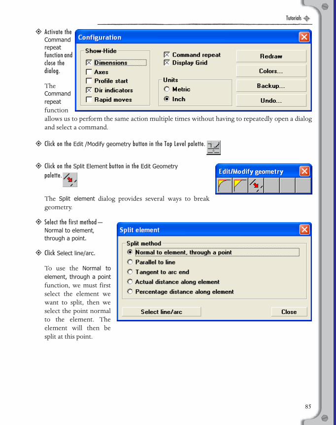
Tutorials
EDM Manual.book Page 85 Wednesday, May 31, 2006 1:14 PM
� Activate the Command repeat function and close the dialog.
TheCommandrepeatfunctionallows us to perform the same action multiple times without having to repeatedly open a dialogand select a command.
� Click on the Edit /Modify geometry button in the Top Level palette.
� Click on the Split Element button in the Edit Geometry
palette.
The Split element dialog provides several ways to breakgeometry.
� Select the first method—Normal to element, through a point.
� Click Select line/arc.
To use the Normal toelement, through a pointfunction, we must firstselect the element wewant to split, then weselect the point normalto the element. Theelement will then besplit at this point.
85
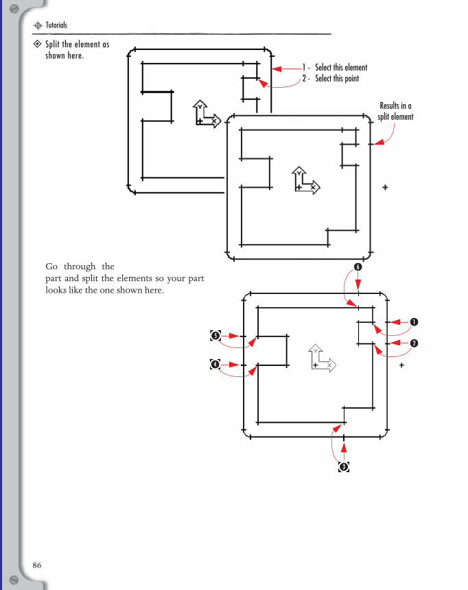
Tutorials
EDM Manual.book Page 86 Wednesday, May 31, 2006 1:14 PM
� Split the element as shown here.
Go through thepart and split the elements so your partlooks like the one shown here.
1 - Select this element2 - Select this point
Results in a split element
86
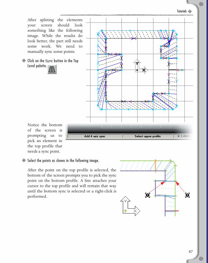
Tutorials
EDM Manual.book Page 87 Wednesday, May 31, 2006 1:14 PM
After splitting the elementsyour screen should looksomething like the followingimage. While the results dolook better, the part still needssome work. We need tomanually sync some points.
� Click on the Sync button in the Top Level palette.
Notice the bottomof the screen isprompting us topick an element inthe top profile thatneeds a sync point.
� Select the points as shown in the following image.
After the point on the top profile is selected, thebottom of the screen prompts you to pick the syncpoint on the bottom profile. A line attaches yourcursor to the top profile and will remain that wayuntil the bottom sync is selected or a right-click isperformed.
87

Tutorials
EDM Manual.book Page 88 Wednesday, May 31, 2006 1:14 PM
After clicking the two pointsyou will see that the points arenow synced. The toolpathlooks a little better. We havesome more syncs to addhowever to complete the part.
� Add syncs at each of the elements that we split. When you are done, the toolpath should look like the image on the right.
This is better, but the toolpath at thecorners is still not optimal. We will notget clean, sharp corners with thistoolpath. We will need to add syncs fromsome of the corners of the top profile tothe rounded corners of the bottomprofile. Remember each element mayhave two syncs.
88

Tutorials
EDM Manual.book Page 89 Wednesday, May 31, 2006 1:14 PM
� Add a sync from the corners to the ends of the rounded corners as shown here.
This is better. The exterior corners arecontrolled but the toolpath is still notoptimal in the interior corners. Theway to fix this is to have overlappingsyncs from the interior corners.
89
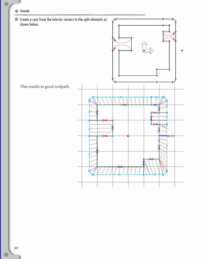
Tutorials
EDM Manual.book Page 90 Wednesday, May 31, 2006 1:14 PM
� Create a sync from the interior corners to the split elements as shown below.
This results in good toolpath.
90

Tutorials
EDM Manual.book Page 91 Wednesday, May 31, 2006 1:14 PM
� Switch to isometric view to see the part complete with all of the skim cuts.
� Click on the Simulation button to see the rendered part.
� Be sure to save the part.
91

Tutorials
EDM Manual.book Page 92 Wednesday, May 31, 2006 1:14 PM
TUTORIAL #3 WIRE EDM OPEN PROFILE
In this tutorial you will learn how to create a Wire EDM part from open profile geometry. Anopen profile part is really not that different than a closed profile part, but there are certain thingsto keep in mind.
� Launch GibbsCAM and open the part Open Profile.vnc.
The part should look like the following image.
� Select all of the geometry on the screen and transfer the data to the Wire EDM package.
The first thing we need to do is to set the wire configuration andstrategy.
� Click on the Wire Configuration button. It is the top left button in the Top Level palette.
92
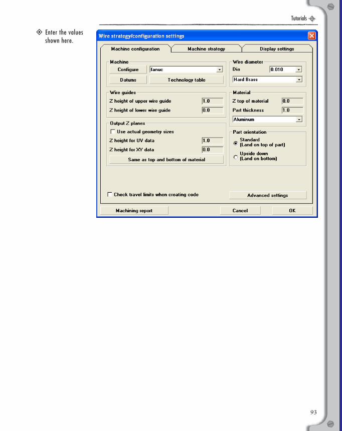
Tutorials
EDM Manual.book Page 93 Wednesday, May 31, 2006 1:14 PM
� Enter the values shown here.
93
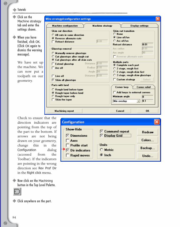
Tutorials
EDM Manual.book Page 94 Wednesday, May 31, 2006 1:14 PM
� Click on the Machine strategy tab and enter the settings shown.
� When you have finished, click OK. (Click OK again to dismiss the warning message).
We have set upthe machine. Wecan now put atoolpath on ourgeometry.
Check to ensure that thedirection indicators arepointing from the top ofthe part to the bottom. Ifarrows are not beingdrawn on your geometry,change this in theConfiguration dialog(accessed from theToolbar). If the indicatorsare pointing in the wrongdirection see Rev Prof Dirin the Right click menu.
� Now click on the Machining button in the Top Level Palette.
� Click anywhere on the part.
94
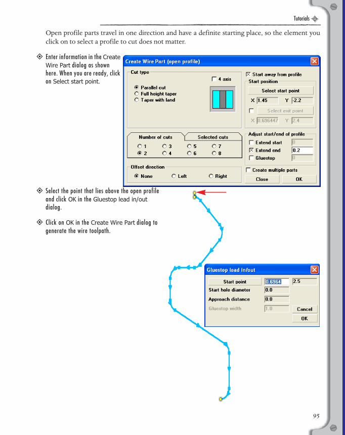
Tutorials
EDM Manual.book Page 95 Wednesday, May 31, 2006 1:14 PM
Open profile parts travel in one direction and have a definite starting place, so the element youclick on to select a profile to cut does not matter.
� Enter information in the Create Wire Part dialog as shown here. When you are ready, click on Select start point.
� Select the point that lies above the open profile and click OK in the Gluestop lead in/out dialog.
� Click on OK in the Create Wire Part dialog to generate the wire toolpath.
95
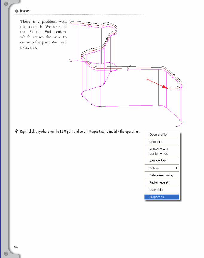
Tutorials
EDM Manual.book Page 96 Wednesday, May 31, 2006 1:14 PM
96
There is a problem withthe toolpath. We selectedthe Extend End option,which causes the wire tocut into the part. We needto fix this.
� Right-click anywhere on the EDM part and select Properties to modify the operation.

Tutorials
EDM Manual.book Page 97 Wednesday, May 31, 2006 1:14 PM
� Turn off Start away from profile and Extend end. Enter a Normal Entry/Exit move of 0.25 as shown here and click on Update to change the operation.
The results of the modifiedoperation look much betterwith a sufficient lead-in andlead-out. We are now goingto make one lastmodification to this part,which is to add a taper.
97
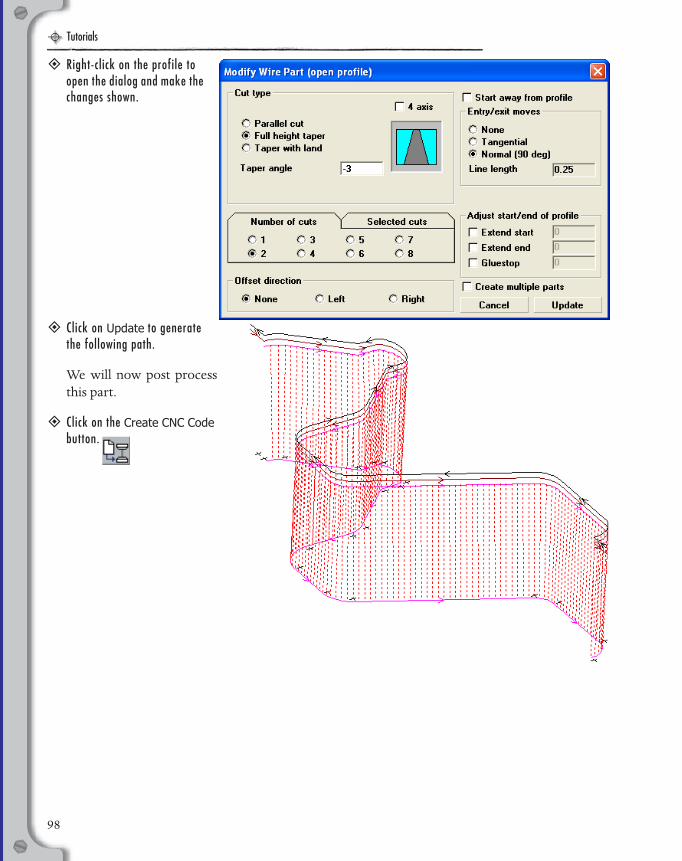
Tutorials
EDM Manual.book Page 98 Wednesday, May 31, 2006 1:14 PM
� Right-click on the profile to open the dialog and make the changes shown.
� Click on Update to generate the following path.
We will now post processthis part.
� Click on the Create CNC Code button.
98
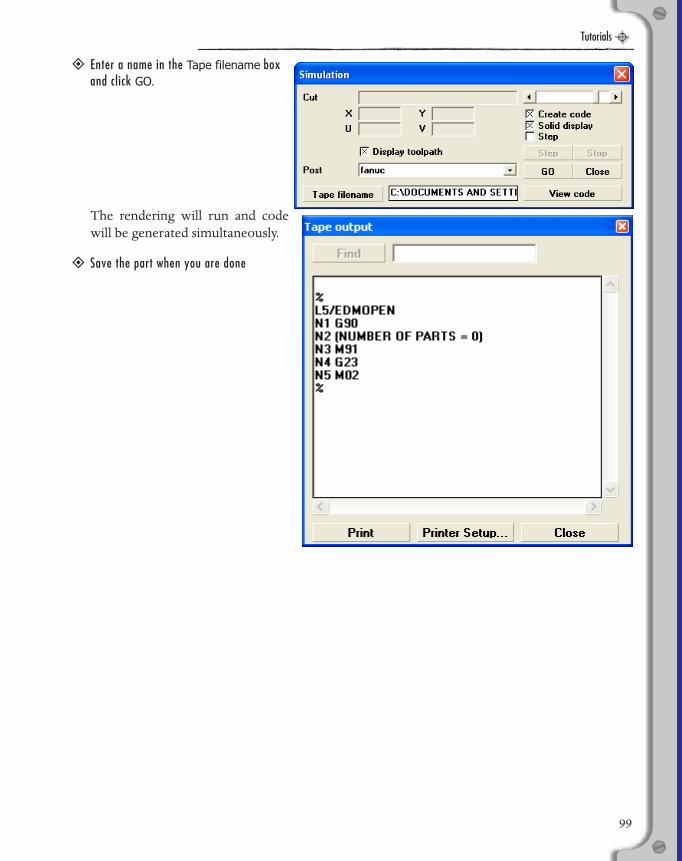
Tutorials
EDM Manual.book Page 99 Wednesday, May 31, 2006 1:14 PM
� Enter a name in the Tape filename box and click GO.
The rendering will run and codewill be generated simultaneously.
� Save the part when you are done
99

Tutorials
EDM Manual.book Page 100 Wednesday, May 31, 2006 1:14 PM
100
EDM Manual.book Page 101 Wednesday, May 31, 2006 1:14 PM
INDEX

EDM Manual.book Page 102 Wednesday, May 31, 2006 1:14 PM
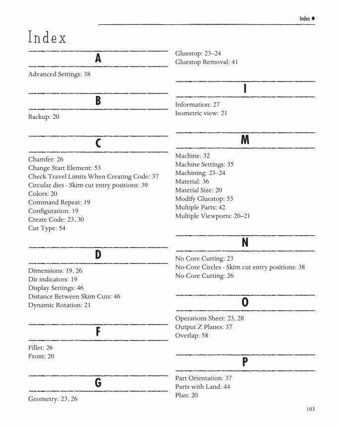
Index ◆
I n d e x
EDM Manual.book Page 103 Wednesday, May 31, 2006 1:14 PM
AAdvanced Settings: 38
BBackup: 20
CChamfer: 26Change Start Element: 53Check Travel Limits When Creating Code: 37Circular dies - Skim cut entry positions: 39Colors: 20Command Repeat: 19Configuration: 19Create Code: 23, 30Cut Type: 54
DDimensions: 19, 26Dir indicators: 19Display Settings: 46Distance Between Skim Cuts: 46Dynamic Rotation: 21
FFillet: 26Front: 20
GGeometry: 23, 26
Gluestop: 23–24Gluestop Removal: 41
IInformation: 27Isometric view: 21
MMachine: 32Machine Settings: 35Machining: 23–24Material: 36Material Size: 20Modify Gluestop: 53Multiple Parts: 42Multiple Viewports: 20–21
NNo Core Cutting: 23No-Core Circles - Skim cut entry positions: 38No-Core Cutting: 26
OOperations Sheet: 23, 28Output Z Planes: 37Overlap: 58
PPart Orientation: 37Parts with Land: 44Plan: 20
103
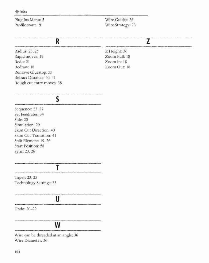
Index
EDM Manual.book Page 104 Wednesday, May 31, 2006 1:14 PM
Plug-Ins Menu: 5Profile start: 19
RRadius: 23, 25Rapid moves: 19Redo: 21Redraw: 18Remove Gluestop: 55Retract Distance: 40–41Rough cut entry moves: 38
SSequence: 23, 27Set Feedrates: 34Side: 20Simulation: 29Skim Cut Direction: 40Skim Cut Transition: 41Split Element: 19, 26Start Position: 58Sync: 23, 26
TTaper: 23, 25Technology Settings: 33
UUndo: 20–22
WWire can be threaded at an angle: 36Wire Diameter: 36
Wire Guides: 36Wire Strategy: 23
ZZ Height: 36Zoom Full: 18Zoom In: 18Zoom Out: 18
104