wireless electronics model # osi-433n remote … · the foregoing mechanical instructions apply to...
TRANSCRIPT
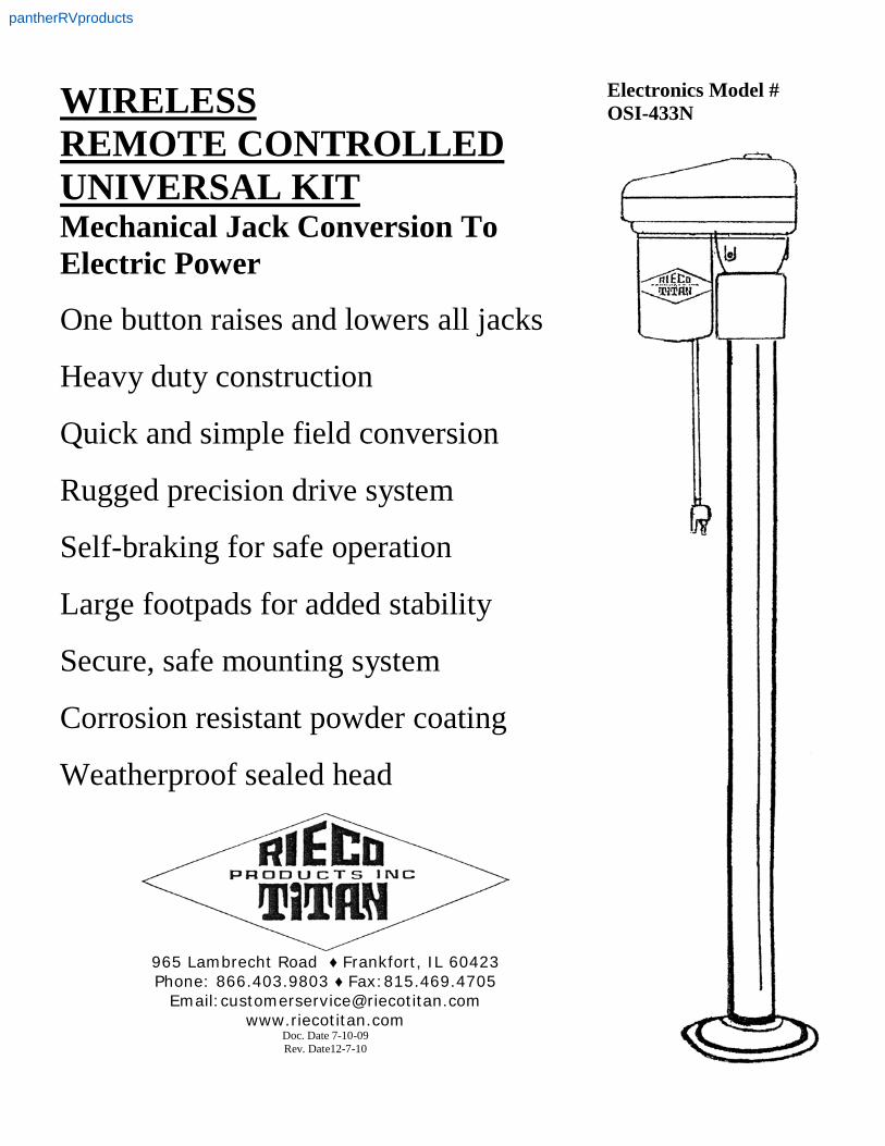
WIRELESS REMOTE CONTROLLED UNIVERSAL KIT Mechanical Jack Conversion To Electric Power
One button raises and lowers all jacks
Heavy duty construction
Quick and simple field conversion
Rugged precision drive system
Self-braking for safe operation
Large footpads for added stability
Secure, safe mounting system
Corrosion resistant powder coating
Weatherproof sealed head
965 Lambrecht Road ♦ Frankfort, IL 60423 Phone: 866.403.9803 ♦ Fax:815.469.4705
Email:[email protected] www.riecotitan.com
Doc. Date 7-10-09 Rev. Date12-7-10
Electronics Model # OSI-433N
pantherRVproducts
2
CAUTION !!! If your jacks are ball screw type, with tube welded to side of gear box, make sure your camper is on your truck or supported on blocks, so that the camper cannot tip over while you are working on this conversion! Note -The installation instructions for this conversion kit follow. Basic instructions are shown for the Acme screw drive jacks. Alternate instructions are included for installation of the conversion kit on Atwood ball screw drive jacks. REMINDER: Make sure your camper is supported by your truck bed or on blocks to prevent it from tipping over while you do this electric conversion.
Revised 8-24-08
pantherRVproducts
3
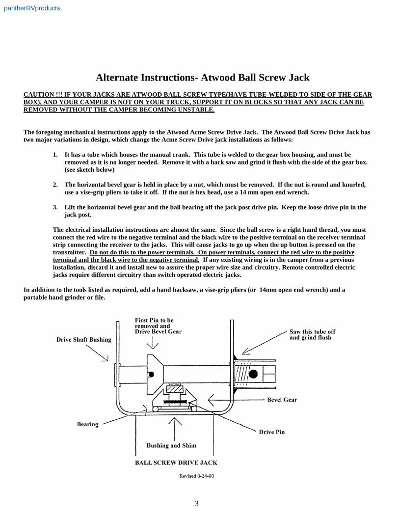
Alternate Instructions- Atwood Ball Screw Jack CAUTION !!! IF YOUR JACKS ARE ATWOOD BALL SCREW TYPE(HAVE TUBE-WELDED TO SIDE OF THE GEAR BOX), AND YOUR CAMPER IS NOT ON YOUR TRUCK, SUPPORT IT ON BLOCKS SO THAT ANY JACK CAN BE REMOVED WITHOUT THE CAMPER BECOMING UNSTABLE. The foregoing mechanical instructions apply to the Atwood Acme Screw Drive Jack. The Atwood Ball Screw Drive Jack has two major variations in design, which change the Acme Screw Drive jack installations as follows:
1. It has a tube which houses the manual crank. This tube is welded to the gear box housing, and must be
removed as it is no longer needed. Remove it with a hack saw and grind it flush with the side of the gear box. (see sketch below)
2. The horizontal bevel gear is held in place by a nut, which must be removed. If the nut is round and knurled,
use a vise-grip pliers to take it off. If the nut is hex head, use a 14 mm open end wrench. 3. Lift the horizontal bevel gear and the ball bearing off the jack post drive pin. Keep the loose drive pin in the
jack post. The electrical installation instructions are almost the same. Since the ball screw is a right hand thread, you must connect the red wire to the negative terminal and the black wire to the positive terminal on the receiver terminal strip connecting the receiver to the jacks. This will cause jacks to go up when the up button is pressed on the transmitter. Do not do this to the power terminals. On power terminals, connect the red wire to the positive terminal and the black wire to the negative terminal. If any existing wiring is in the camper from a previous installation, discard it and install new to assure the proper wire size and circuitry. Remote controlled electric jacks require different circuitry than switch operated electric jacks.
In addition to the tools listed as required, add a hand hacksaw, a vise-grip pliers (or 14mm open end wrench) and a portable hand grinder or file.
Revised 8-24-08
pantherRVproducts
4
Rieco-Titan Products, Inc. 965 Lambrecht Road Frankfort, IL 60423 Phone: 866.403.9803 Fax: 815.469.4705
MECHANICAL JACK CONVERSION TO ELECTRIC POWER
INSTALLATION & OPERATING
INSTRUCTIONS
Universal Kit
Revised 6-13-08
2000# Mechanical Jacks
SAFETY ALERT! This symbol - !!! is used here to alert you to potential personal safety hazards and property damage. Obey all safety messages that follow this symbol to avoid possible property damage, injury or death. Camper manufacturers must insure that camper wall corners are adequately reinforced for mounting jacks. MECHANICAL INSTALLATION- Tools Required: Adjustable Wrench, 5/16” open end wrench, standard straight blade screwdriver and hammer. Vise-grip pliers for holding pin punch.
1. Remove all components from shipping cartons and check to assure that the following components are included. Notify Rieco-Titan if any parts are missing.
(4) Electric Gearmotors and (4) gearbox covers (4) Electric Receptacles with wiring (1) Hand Held Transmitter (1) Transmitter to Receiver Cable (1) Receiver/Control Relay Box (8) 5/8 – 18 x ¾ long Hex Cap Screws (1) Remote Switch Panel (8) 5/8- 18 Hex Thin Jam Locknuts (4) ¾ Diameter x 3 27/32” L Drive Tube w/ Collars (1) 5/32 Pin Punch & (1) 5/32 Allen Key (4) Gearmotor Mounting Brackets (4) 5/32 x ¾ “ Drive Pins (4) Round Rubber Gaskets (4) Steel Bushings
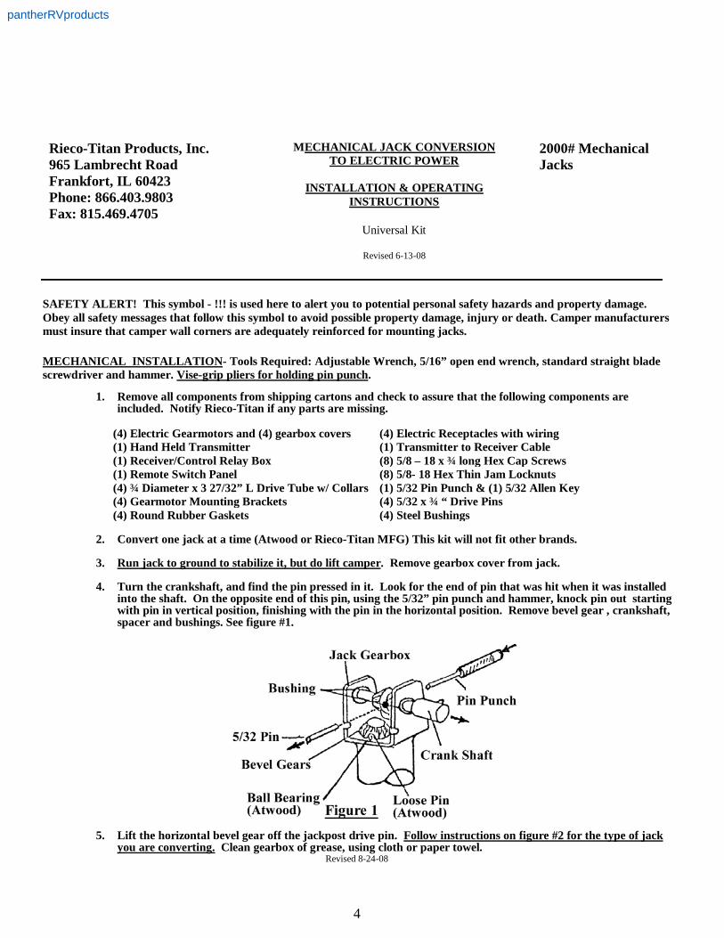
2. Convert one jack at a time (Atwood or Rieco-Titan MFG) This kit will not fit other brands. 3. Run jack to ground to stabilize it, but do lift camper. Remove gearbox cover from jack. 4. Turn the crankshaft, and find the pin pressed in it. Look for the end of pin that was hit when it was installed
into the shaft. On the opposite end of this pin, using the 5/32” pin punch and hammer, knock pin out starting with pin in vertical position, finishing with the pin in the horizontal position. Remove bevel gear , crankshaft, spacer and bushings. See figure #1.
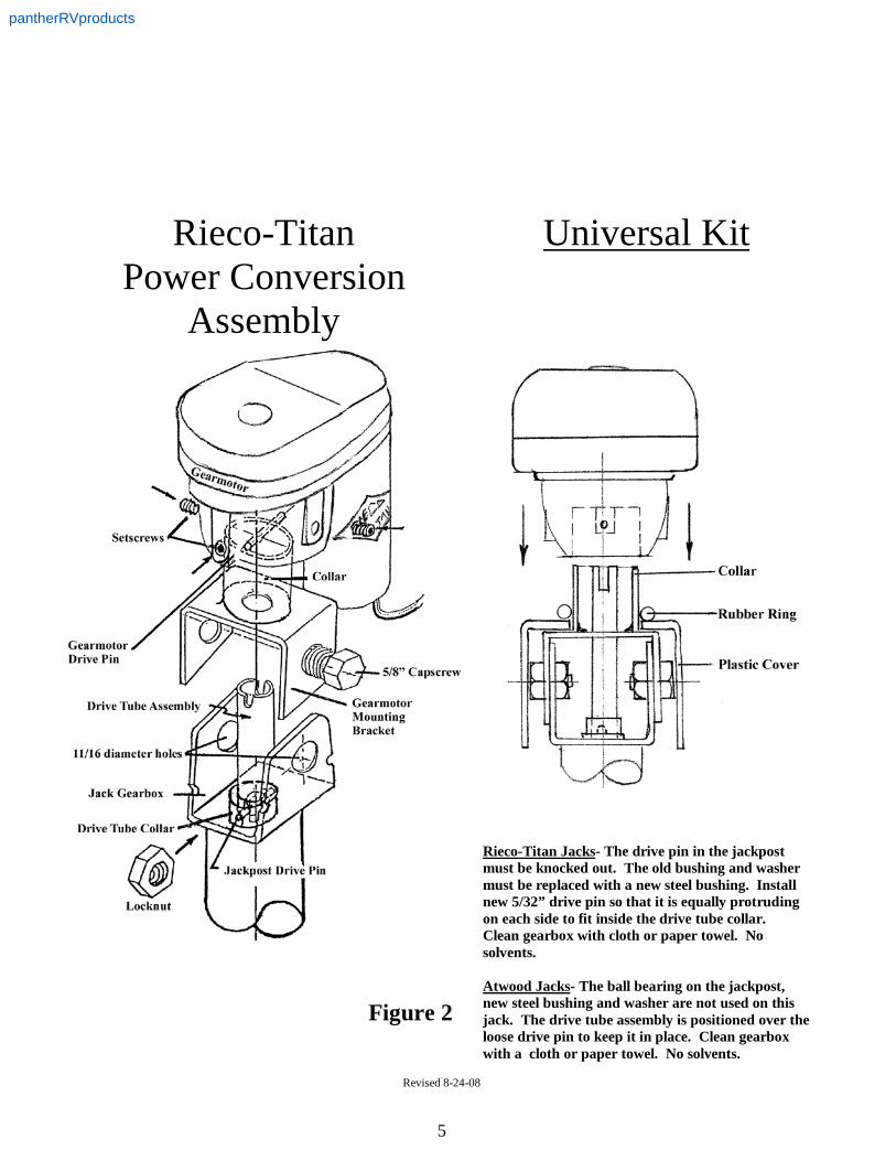
5. Lift the horizontal bevel gear off the jackpost drive pin. Follow instructions on figure #2 for the type of jack
you are converting. Clean gearbox of grease, using cloth or paper towel. Revised 8-24-08
pantherRVproducts
5
Rieco-Titan
Power Conversion Assembly
Figure 2
Universal Kit
Rieco-Titan Jacks- The drive pin in the jackpost must be knocked out. The old bushing and washer must be replaced with a new steel bushing. Install new 5/32” drive pin so that it is equally protruding on each side to fit inside the drive tube collar. Clean gearbox with cloth or paper towel. No solvents. Atwood Jacks- The ball bearing on the jackpost, new steel bushing and washer are not used on this jack. The drive tube assembly is positioned over the loose drive pin to keep it in place. Clean gearbox with a cloth or paper towel. No solvents.
Revised 8-24-08
pantherRVproducts

6
MECHANICAL INSTALLATION (continued)
6. Obtain the gearmotor mounting bracket. Position it so that the 11/16 diameter holes line up with the holes in
the jack gearbox. The mounting bracket collar is offset 1/8” to one side. On Rieco-Titan jacks, install bracket so that the bracket offset matches offset in gearbox. On Atwood jacks, mount bracket without regard to offset in bracket. Gearbox drive pin and mounting bracket hole must be aligned vertically with torque tube, so that the slots engage the drive pin on the jackpost driveshaft. Turn torque tube with screwdriver to line up drive pin as shown in Figure 2.
7. Obtain the two 5/8 Cap Screws and two locknuts and assemble them into the holes in the gearmotor mounting
bracket and jack gearbox. Start the locknuts inside the jack gearbox. (As shown in Figure 2) 8. Tighten cap screws and locknuts using a 15/16” open wrench inside, adjustable wrench outside. 9. Obtain a gearmotor, a plastic gearbox cover, and a rubber gasket. 10. Position the plastic gearbox cover , the rubber gasket and gearmotor onto the collar of the gearmotor
mounting bracket. Make sure that the gearmotor drive pin lines up as shown on figure 2 and that the slot in the torque tube engages freely. Tighten the three set screws in the gearmotor hub to fasten them in place.
11. !!! Check and tighten the lag screws holding the jacks and mounting brackets to the camper. Repeat steps 3
through 11 on the remaining jacks. 12. As a final installation procedure, it is necessary that you coat the entire surface of the jacks and brackets with
a liquid wax such as Mother’s Polish, McGuires, or Turtle Wax. An excellent alternate is Mercury’s Corrosion Guard. This will prevent corrosion and maintain the beauty of the jacks.
ELECTRICAL INSTALLATION
1. The electric jack kit comes equipped with four (4) female receptacles and cords. Each jack has a cord with a male plug that accesses power through the receptacle. The receptacle must be mounted in close proximity to the jack near each corner of the camper.
2. Wire the receptacles as shown on the diagram in figure 3. The receptacle is a flange design which fits snugly
into a 7/8" diameter hole which must be drilled into the exterior wall of the camper. Fasten to the camper wall with two screws 6“ from the edge of the camper.
3. Interior wires connecting the receptacles to the receiver control box should be #10 AWG copper stranded 600
V, UL wire, using locking spade connectors for #10 studs. 4. The interior wiring from these receptacles can be routed up to the top of the camper, and run above the
ceiling line to avoid the tedious routing through the various lower compartment walls. Alternately, they can be brought out and routed externally to a point where they re-enter the camper for connection to the receiver control box terminals.
5. Install a heavy duty Marine/RV battery in the camper with charging provisions. Locate the battery in a
separate compartment, but near the receiver control box.
Revised 8-24-08
pantherRVproducts
7
ELECTRICAL INSTALLATION ( continued )
6. Connect the two wires from each jack to the receiver. The left front jack should be connected to the receiver
terminals marked LF. The right front to the RF terminals, and so on for the rear jacks. Each set of terminals has a (+) and a (-) side. Connect according to the wiring diagram shown in figure 3. Red wire is positive; black wire is negative.
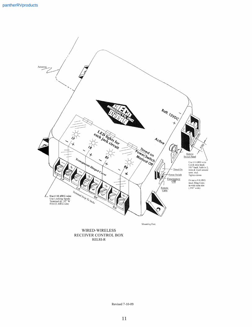
7. Mount the receiver control box near a compartment door to maximize transmitter wire length outside the
camper. Also, locate it as close to the battery compartment as feasible. Use #8 AWG wire to connect the battery terminals to the power input terminals in the receiver control box. Use a ring connector (or split wire)
8. !!! Install a 60 amp circuit breaker in the wiring to protect the receiver control box electronics.*
9. The negative lead from the battery must be connected to the negative terminal, and the positive lead from the battery must connect to the positive terminal in the receiver control box. !!! ( See special note of caution, below )
10. The transmitter can be used in either one of these modes: (1) Wired, with a cable and plug connection to the
receiver control box or remote switch panel (2) Wireless, which is operated with a 12 volt battery, sending radio frequency signals to an antennae in the receiver control box.
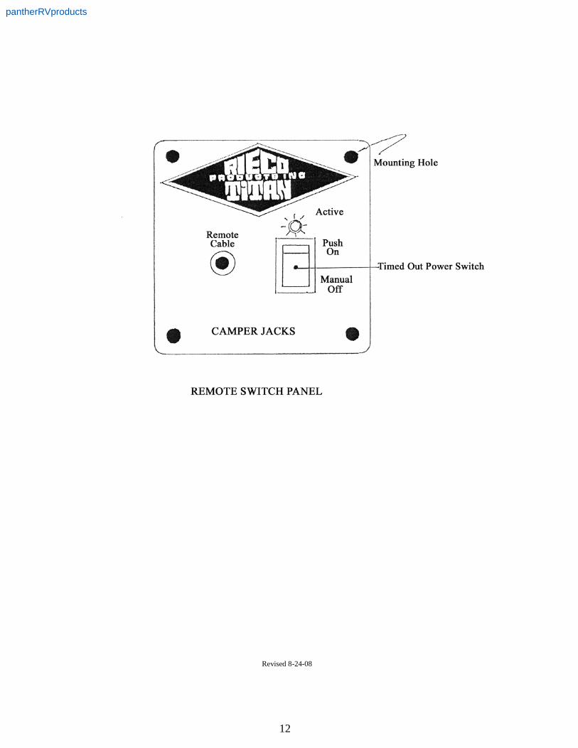
11. A remote “ on-off “ switch panel is provided to control the power to the system. This switch should be
mounted inside the camper, near the door. The switch is equipped with an LED light which is lit when the power is on. The power stays on for 15 minutes, and then automatically shuts off along with the LED light, stopping any possible operation of the jack system. (This safety feature eliminates the need to remember to switch the system "off") Plug the attached cable from the remote switch panel into the receiver control box. Whenever the LED light is off, it will be necessary to press the "on" switch to restore power to the system to operate the jacks. The receiver control box and the remote switch panel have manual off controls.
12. The wireless transmitter needs no wired connection from the transmitter to the receiver control box, but
instead, an antennae wire is provided to pick up the RF (radio frequency) commands. !!! CAUTION !!! Do not connect 12VDC power from the battery to any receiver terminals except the two 12VDC battery terminals marked on the receiver case. To do so will burn out the receiver. This is not covered by the warranty. * Item # 8 above - 60 Amp circuit breaker can be acquired from Rieco- Titan Products, Inc. 866-403-9803. Part # 46931
Revised 8-24-08
pantherRVproducts
8
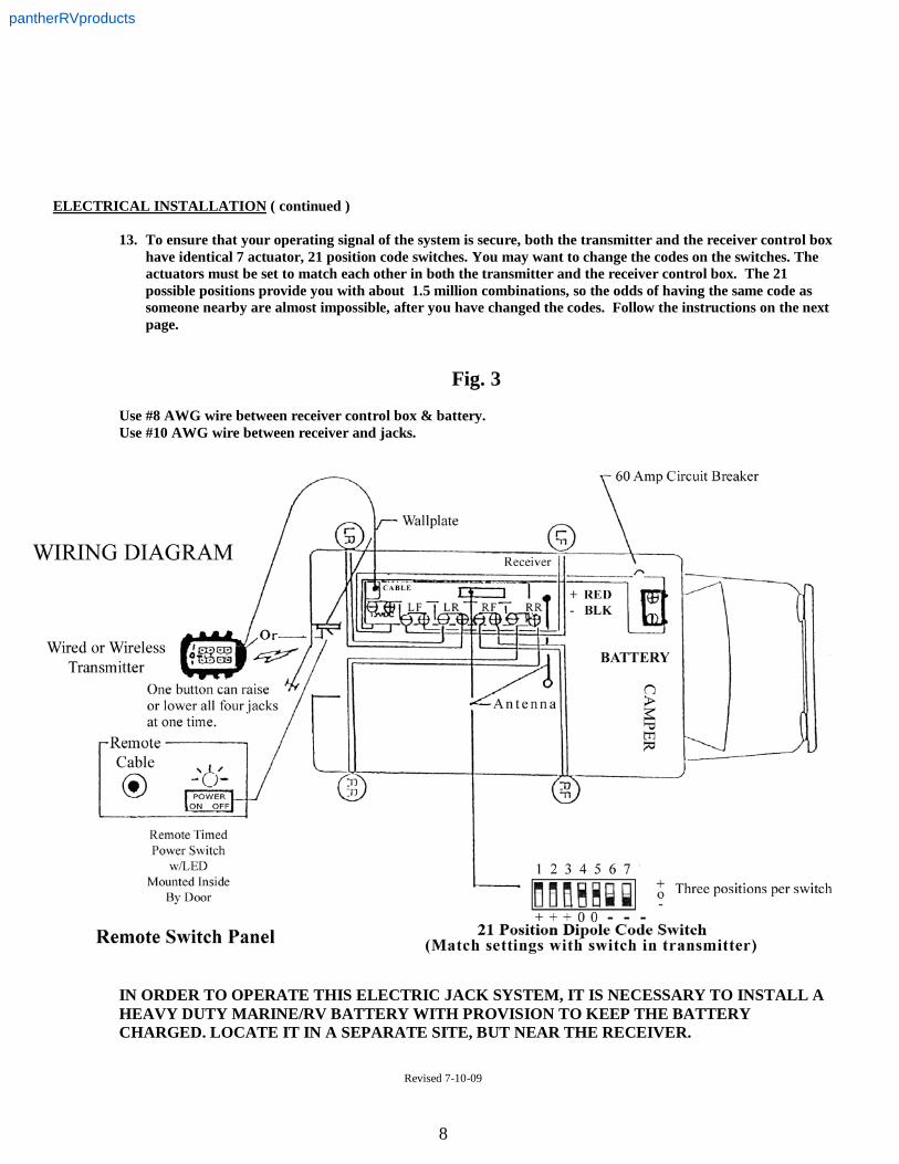
ELECTRICAL INSTALLATION ( continued ) 13. To ensure that your operating signal of the system is secure, both the transmitter and the receiver control box
have identical 7 actuator, 21 position code switches. You may want to change the codes on the switches. The actuators must be set to match each other in both the transmitter and the receiver control box. The 21 possible positions provide you with about 1.5 million combinations, so the odds of having the same code as someone nearby are almost impossible, after you have changed the codes. Follow the instructions on the next page.
Fig. 3
Use #8 AWG wire between receiver control box & battery. Use #10 AWG wire between receiver and jacks.
IN ORDER TO OPERATE THIS ELECTRIC JACK SYSTEM, IT IS NECESSARY TO INSTALL A HEAVY DUTY MARINE/RV BATTERY WITH PROVISION TO KEEP THE BATTERY CHARGED. LOCATE IT IN A SEPARATE SITE, BUT NEAR THE RECEIVER.
Revised 7-10-09
pantherRVproducts
9
ELECTRICAL INSTALLATION ( Continued )
14. CODE SWITCH SETTING The codes in the code switches are set at the factory to match both the receiver and the transmitter as a set. If you wish to reset the codes to your own selection, follow this procedure: The code switches are located inside the receiver, and inside the transmitter.
a. Remove the four screws and the cover.
b. Inside the enclosure, locate the code switch block. There are seven (7) switches. Each switch has three (3) positions +, 0 , —.
c. As you read the numbers left to right, set the switches to one of the three positions on each switch.
d. Record your setting on a slip of paper i.e. sw 1=0 or sw 1=+ or sw= —. Proceed to record all seven (7)
settings in this fashion.
e. Take your recorded switch settings to the next unit to be set and begin setting switches left to right as shown on your recorded slip of paper, making the settings exactly the same as the last unit set.
f. Put the receiver and the transmitter side by side and carefully check to make sure that they are set
identically.
g. Replace the covers on both units and save the code setting record for future reference. (On units that have serial numbers, a code setting is given at the factory. This setting can be used as is or any new setting should be recorded.)
NOTE : IF YOU DO NOT HAVE A CODE SETTING LIST FROM YOUR DEALER, OR IF YOU DO NOT HAVE A SERIAL NUMBER AFFIXED TO YOUR RECEIVER OR TRANSMITTER, THE CODES ARE ALL AT "0", AND YOU SHOULD RESET THEM TO A CODE OF YOUR SELECTION. IF YOU HAVE SERIAL NUMBERS ON YOUR UNITS, YOUR FACTORY CODE SETTING IS AVAILABLE FROM RIECO-TITAN PRODUCTS, INC.
15. Our new receiver control box is equipped with an LED light in the top for each jack circuit. When the jack is
activated by the remote button control, the LED for that jack or jacks is illuminated indicating a completed circuit. Also included inside the box are eight 30 amp automotive blade type fuses (2 per jack). If a short circuit occurs, or a current overload happens, the fuse will burn protecting the electronics and the motors.
It is important to find the cause of the blown fuse before replacing the fuse.
16. EMERGENCY REMOTE CONTROL The electronic control system now includes a remote emergency
button control, which can take a great deal of the exasperation and sweat out of the lost or damaged remote control situation. The emergency button control is colored bright red, and is intended for use in emergency situations only. It will operate your electric jacks with electricity, rather than have you mechanically crank them to get you on the road again. This new control operates in the wired mode only, not RF (wireless) , but will do the job. It will be found attached to the receiver control box in the camper. The control comes with a special red connector wire to plug into the remote switch panel to operate the system. We suggest that as soon as a replacement is obtained for the lost or damaged remote control, the emergency units be returned to their storage location for possible future emergency use. This emergency control has the same security code setting as your regular remote and receiver control box.
Revised 4-1-10
pantherRVproducts

10
Fig. 4 The “C” clamp and the 5” bracket are intended to be used when the camper manufacturer recommends their use. When they are called for, use three (3) bolts on the 13” bracket and one (1) on the 5” bracket. The 5” bracket is used on the left and right rear of the camper beneath the 13” bracket. Fig. 5 The wired remote transmitter is shown here. It is the electrical control device that operates the electric jacks. The operation buttons are arranged by jack location. The left side is the driver’s side, and the right side is the passenger’s side of the camper. The top section buttons control the front jacks, middle section, all jacks and the bottom section, the rear jacks. The “UP” arrow signifies lift the camper, while the “DOWN” arrow means lower the camper. The cable on the wired transmitter is plugged into the remote switch panel. * The wireless transmitter contains a 12-volt battery to power the RF (radio frequency) signal commands it sends to the antenna coming out of the receiver control box. * For best wireless performance of the electric jack controls, it is recommended that you install a fresh battery in the hand held remote control at the begining of each season ( 1 per year ) This will insure that the radio control signal is strong and effective. The battery is # A-23 12 Volt Alkaline. It is available at Walgreens, Radio Shack, and battery stores. * The transmitter cable can also be plugged directly into the receiver control box.
NOTE: THE BUTTONS ON THE TRANSMITTER FUNCTION AS FOLLOWS: THE “UP” ARROW SIGNIFIES LIFT THE CAMPER, WHILE THE “DOWN” ARROW MEANS LOWER THE CAMPER. Revised 8-24-08
pantherRVproducts
11
Revised 7-10-09
pantherRVproducts
12
Revised 8-24-08
pantherRVproducts
13
!!! FOLLOW THE SAFETY RECOMMENDATIONS LISTED BELOW TO AVOID POSSIBLE INJURY AND/OR PROPERTY DAMAGE
1. This jack system is designed and intended for loading, unloading, and stabilizing your truck camper while in storage. Do not allow a person or persons in your camper while the jacks
are in use.
2. Never exceed the rated capacity of your camper and jack system. This jack system is rated at 2,500 lbs. per jack, 5,000 lbs. net camper weight.
3. Do not store your camper in a windy area, or on spongy soil. Do not place blocks under your jacks for additional lift or clearance. These jacks lift a full 36".
4. Maintain a fully charged battery.
5. When using jacks, always remain in full view of jacks being moved.
6. Never raise the rear of the camper higher than the front of the camper.
7. In freezing weather, when your camper is up on jacks, be aware that your jack footpads may be buried or frozen in ice. This can cause damage to the corners of your camper when you lift the jacks off the ground. Clear off any ice before you lift the jacks up.
8. Always keep the power switch in the “OFF” position when system is not in use.
9. Never over- extend or over- retract jacks past their full travel limits. Jacks have a slip clutch that prevents damage. However, when a clicking noise is heard, release the transmitter button immediately. The wiring is equipped with circuit breakers that automatically reset in 20 seconds if motors become over heated.
10. Store transmitter in a secure location inaccessible to children.
OPERATING INSTRUCTIONS
UNLOADING THE CAMPER
1. !!! Disconnect all camper tie downs and electric devices from truck. Always keep front of camper higher or level with rear of the camper.
2. Push the power switch "ON". This powers the jack system so that one, two or four jacks may be actuated simultaneously.
3. Press the "UP" buttons on the transmitter for the two front jacks until the jacks make contact with the ground.
4. Repeat step 3 for the two rear jacks.
5. Press the "UP" buttons for the two front jacks, raise the front of the camper 3-4".
6. Press the "UP" buttons for the two rear jacks until the rear of the camper is level with the front.
7. Continue the above lifting procedure until the camper is approximately 6" above the truck bed or until it clears the highest point on the truck bed.
8. !!! Carefully drive the truck forward taking care not to hit or rub the camper jacks, truck wheels or fenders.
LOWERING THE CAMPER
Always lower the rear of the camper first, 3-4" at a time. Lower the rear jacks then the front jacks until they are level with the rear. Then lower the rear jacks again. Continue this procedure until the desired height is reached. Turn off power on the receiver control box when lowering is complete.
Doc. Date 8-24-08 Rev. Date 2-02-09
pantherRVproducts
14
LOADING THE CAMPER
1. Push the rocker switch "ON" in the receiver unit or the remote switch panel.
2. Press the "UP" buttons on the transmitter until the two front jacks have raised the camper 3-4".
3. Raise the two rear jacks 3-4" until level with front.
4. Repeat steps 2 & 3 until camper is approximately 6" above truck bed or highest point on truck bed.
5. !!! Back truck carefully under the camper, making sure to not hit or rub the camper jacks, truck wheels or fenders.
6. Make sure any ice is cleared away from the jack footpads(see safety recommendations, page 9)
7. Lower the camper onto the truck by following the instructions in the "LOWERING THE CAMPER" section.
MANUAL OPERATION
If the battery power is low, switch the power "OFF" to the receiver. This will eliminate the dynamic braking effect of the motor. Remove the access cap on the top of the powerhead. The crank shaft of the gearbox will be accessible to turn with a 3/8" ratchet wrench. Rotate the wrench counter-clockwise to raise the jack and clockwise to lower the jack. Do not activate the motor with the wrench still on the crank shaft.
CAMPER STORAGE
Jacks can be used for permanent storage. However, for best stability, set the camper on blocks, and use the jacks for stabilizing only.
LIFTING AND LOWERING - ALL JACKS MODE
The front jacks lift the heaviest load, and consequently will raise slower than the rear jacks. Conversely, the front jacks will lower faster than the rear jacks. This phenomenon will be most noticeable when using the "ALL" jacks button on the transmitter. It is necessary that the camper level condition be closely watched so as to prevent the rear of the camper from being at a higher level than the front. It will be necessary to stop the "ALL" jacks operation to keep the level condition of the camper even front to back and side to side.
MAINTENANCE
The internal parts of the jack system are permanently lubricated and should not require further lubrication. Once each year, run each jack out to its full extent, and clean the outer surface of the inner tube. Spray this surface with silicone spray lubricant. Clean outer surface of housing and spray the manual crank shaft with silicone lubricant. Apply a good auto wax to the outer surfaces of the jack system to maintain an attractive appearance. In coastal, rainy, or humid areas, we recommend that a liquid wax such as Mother’s Polish, McGuires, or Turtle Wax be applied to the entire surface of the jacks and brackets. Keep the wax intact with a spray wax periodically. Repeat each year. An excellent alternate is Mercury’s Corrosion Guard.
The electronic components of the jack system also require very little maintenance. The remote transmitter can be cleaned periodically with a soft damp cloth. Solvents or cleaners are to be avoided since they can leak inside causing electrical damage. Wipe battery contacts with a dry lint-free cloth. If the transmitter or receiver get wet, open their respective covers, and dry thoroughly before re-using.
Doc. Date 8-24-08 Rev. Date 2-02-09
pantherRVproducts
15
TROUBLE SHOOTING
For any control or electrical malfunction, check the following things to find the cause: -- Make sure that the receiver power switch is "ON". -- Make sure all cables are firmly plugged into the receptacles. Re-plug if jack is not responding. -- Check camper batteries for charge status. -- Check transmitter for wetness or damage. -- Check transmitter battery and code switches to make sure they match those in control box. After checking the above, if a jack in the system will not operate, replace it, or have it repaired. Call for assistance at Rieco-Titan Products 866-403-9803 !!! You are alerted to avoid interference with blasting operations. Do not use your remote near any area where electrical blasting caps arc stored or used, or in areas posted : TURN OFF TWO- WAY RADIO. Obey all signs and instructions that you see in such areas. Be especially alert in areas with explosive atmospheres. Signs and warnings are not always clearly posted; such as in fueling, and fuel or chemical storage areas where the air contains chemicals, dust, powders or anywhere you are instructed to turn off your vehicle engine.
********* LIMITED WARRANTY *********
The REL-2 is warranted against manufacturing defects and workmanship for two (2) years from the date of purchase. Within this period, RIECO-TITAN PRODUCTS, INC. will at its option, repair or replace the product or any part thereof without charge for parts and labor. To exercise the warranty, the original consumer-owner must return the original invoice, and the product freight prepaid and insured to RIECO-TITAN PRODUCTS, INC.
This warranty does not apply in the following cases; Product finish, improper installation, misuse, failure to follow installation and operating instructions, alterations, abuse, tampering, accident or acts of God or nature. All statements, technical information and recommendations contained herein are based on tests we believe to be reliable, but the accuracy or completeness thereof is not guaranteed and the following is made in lieu of all warranties, expressed or implied. Seller's and manufacturer's only obligation shall be to replace such quantity of the product proved to be defective in accordance with published Warranty Policy. Neither seller nor manufacturer shall be liable for any injury, loss or damage, direct or consequential arising out of the use of or the inability to use the product. Before using, user shall determine the stability of the product for his intended use and user assumes all risk and liability whatsoever in connection therewith.
Except as provided herein, RIECO-TITAN PRODUCTS, INC. makes no express warranties and any implied warrant of merchantability or fitness for a particular purpose is limited to the duration of the written limited warranties set forth herein.
There will be charges rendered on repairs to the product made after the expiration of the aforesaid two (2) year Warranty Period.
This warranty gives you specific legal rights and you may have other rights which may vary from state to state.
********************************************************************************************* Electronic Controls
Model #OSI – 433N FCC ID#PM6HOMPETOSI43 This device complies with part 15 of the FCC rules. Operation is subject to the following two conditions: ( 1 ) This device may not cause harmful interference and ( 2 ) This device must accept any interference received, including interference that may cause undesired operation.
Doc. Date 7-10-09 Rev. Date 12-7-10
pantherRVproducts