wireless image transmission systems of uavs
TRANSCRIPT

sensors
Article
The Improved Image Scrambling Algorithm for theWireless Image Transmission Systems of UAVs
Jie Dong 1, Guowei Wu 1, Tingting Yang 2,* and Yangyang Li 2
1 School of Software, Dalian University of Technology, Road No. 8, Dalian 116620, China;[email protected] (J.D.); [email protected] (G.W.)
2 School of Navigation, Dalian Maritime University, Dalian 116620, China; [email protected]* Correspondence: [email protected]; Tel.: +86-189-0098-2596
Received: 2 September 2018; Accepted: 3 October 2018; Published: 12 October 2018�����������������
Abstract: With the deepening of modern military reforms, information has become the key to winningmodern warfare. The use of unmanned aerial vehicle (UAV) to capture image information has becomean important means of reconnaissance in modern warfare and plays an irreplaceable role. The imageinformation usually uses a wireless image transmission system, since image information is interceptedor stolen easily during the information transmission, encrypting an image is a common method forensuring image security. However, traditional encryption algorithms have some deficiencies in termsof efficiency and security. In order to overcome these shortcomings, a new algorithm is proposed inthis paper-an improved image scrambling encryption algorithm based on Fibonacci-p coding. The firstnew idea of the algorithm is to separate the positive and negative signs and data of the scrambled DCTcoefficients, then form the symbol matrix and the data matrix respectively, perform the scramblingencryption operation on the symbol matrix. The second new idea is to encrypt the color RGB imageby converting the R, G, and B colors into Y, Cb, and Cr, and converting the normal image operationinto operations on Y, Cb, and Cr, thereby implementing the encryption operation. The comprehensiveperformance of the algorithm is optimal with different image information. Experiments resultsvalidate the favorable performance of the proposed improved encryption algorithm.
Keywords: UAV; high-definition long-distance wireless digital image transmission system; improvedimage scrambling encryption algorithm; Fibonacci-p coding
1. Introduction
The biggest advantage of UAVs in combat operations has always been reflected in intelligencereconnaissance. The reconnaissance images obtained by the UAV loaded with various imaging sensorsmust be transmitted to the commanders in real time to make the battlefield transparent. Therefore,the transmission of reconnaissance information is a major aspect of the UAV system and an importantpart of the UAV measurement and control system. Video and flight data collected by various types ofdrones are usually transmitted using a wireless image transmission system. Compared with wiredimage transmission, wireless image transmission has great advantages in terms of mobility and powerconsumption, its real-time performance and image transmission speed and quality are much lowerthan wired image transmission: (1) the image transmission clarity is not enough and the transmissiondistance is close and the application requirements cannot be fulfilled; (2) the communication corridorhas no communication link, and the transmission line patrol video cannot be transmitted back to themonitoring center in real time; (3) patrol data processing, patrol pictures, video analysis, naming,archiving, and query are all manual operations, with low intelligence and low efficiency. Especially thepatrol video and the live tower number cannot automatically correspond, rely on manual operations
Sensors 2018, 18, 3430; doi:10.3390/s18103430 www.mdpi.com/journal/sensors
Sensors 2018, 18, 3430 2 of 16
mainly. Therefore, in connection with the development of drone inspection technology, high-definitionlong-distance wireless digital image transmission system has far-reaching significance.
Image scrambling technology is a common method of image encryption, and is often used as apreprocessing technique for digital watermarking. In the field of image scrambling, many expertsand scholars at home and abroad have proposed different theoretical systems [1], the purpose ofwhich is to provide safer encryption methods. The purpose of image scrambling is to make theencrypted image and the original image statistical information completely different by a certaintransformation algorithm, thereby conserving the real content of the original image. The imagescrambling schemes that have been summarized can be divided into three categories: (1) space-basedscrambling algorithm; (2) color space-based scrambling algorithm [2]; (3) scrambling algorithm basedon position and color space. For the first type of program, experts have proposed many classicalalgorithms, such as Arnold transform, magic square transform, Fibonacci transform, panel changer,Hilbert curve method, Tangram algorithm, IFS model, chaos and so on. This kind of algorithm doesnot change the gray value of the image, no matter how exquisite the algorithm is designed, it can’tchange the basic statistical features of the image (such as histogram), which is easy to attract theattention of the attacker. For the scrambling of the image color space, the classic Gray Code conversionis often used. Hu designed a scrambling transformation system based on Logistic and standardmapping, which changes the image pixel values and generates mutual dependence by alternativetransformation [3], so the encryption algorithm has the basic elements of encryption system such asscrambling, substitution and diffusion. The second type of scheme changes the statistical informationof digital images greatly, but the algorithm itself has limitations, such as the encryption effect is notgood, and the application is not wide, compared with the first two types of schemes, the third schemeof the system scheme expands the algorithm. The key space combines pixel location scramblingand pixel value scrambling to compensate for the mutual defect that is the development direction ofimage scrambling.
In this paper, according to specific requirements of the wireless image transmission systemand combining with the research progress of image encryption technology that an improved imagescrambling encryption algorithm based on Fibonacci-p coding is used. The algorithm combineswith the process of video compression and regulates the parameters of the encryption process thataccording to the content of the video image, so that the comprehensive performance of the algorithmis optimal for different image information. The results of the experiment that the algorithm has goodperformance in the influence of adjacent pixels, and the information entropy of images is more idealthan other algorithms. This work targets to investigate the security issues in military communicationsystem, which is featured by protecting important data. Specifically, the contributions of this paper arethree-fold:
(1) We propose a high-definition long-distance wireless image transmission system to transmit imageinformation to the command center in real time in order to make the battlefield transparent.
(2) A novel algorithm namely improved image scrambling encryption algorithm based on Fibonacci-pcoding is proposed, which has optimal comprehensive performance with respect to thesecurity issue.
(3) It has been proved from the experimental results that the superior performance of the proposedimproved image scrambling encryption algorithm.
The rest of the paper is organized as follows: the Materials and Methods are presented in Section 2.The system model is presented in Section 3. Section 4 presents the improved image encryptionalgorithm. Section 5 provides the experimental results and related analysis. Finally, we conclude ourmain work in Section 6.

Sensors 2018, 18, 3430 3 of 16
2. Materials and Methods
There are two main concepts in wireless image transmission that is real-time video transmission.One is mobile transmission that is mobile communication, and the other is broadband transmissionthat is broadband communication. In the past, wireless image transmission was mainly based onone-way analog TV broadcasting service [4–9]. Mainly, a set of TV programs use a single frequencypoint. The single frequency network can improve the utilization of frequency resources. However,when TV programs are broadcast at the same frequency and at the same frequency in different places,they will interfere with each other. In addition, Since the receiving or transmitting party is in amoving state, whether it is transmitting or receiving, it will encounter strong multipath interference,that is, echo interference. Therefore, the processing of echo interference may fundamentally affect thereal-time transmission of a wireless high-definition video. The performance of the system, and theCOFDM transmission technology in the VFORD8000 wireless digital high-definition video real-timetransmission system is the problem that can effectively use the echo instead of negatively eliminatingthe echo.
In image encryption technology, digital image scrambling technology is very important.In general, the better the effect of image scrambling, as the secret information hidden in the carrierinformation, the stronger the anti-detection capability, the higher the hiding ability. At present,the research on scrambling encryption algorithms for grayscale images has made great progress.Nowadays, the image scrambling algorithms commonly used by researchers include Arnold transform,Hilbert transform, magic square transform, Fibonacci transform and affine transform. Digital imagescrambling technology only scrambles the image space at the beginning, but today, for digital images,only scrambling the image position can’t meet our needs, so people continue to study on this basisand find. In addition to scrambling in the spatial domain of the digital image (including color spaceand location space), the scrambling process can also be performed in the frequency domain of thedigital image. This discovery has led to further improvements in the implementation of digital imagetechnology. As one of the digital image encryption methods, digital image scrambling technologyallows legal users to freely control parameter selection, algorithm selection and random numbertechnology to improve the difficulty of attackers and illegal attacks. For the spatial disturbance of theimage, it just uses an algorithm to destroy the order of the individual pixel positions of the image,making an image “unrecognizable”, in fact the total number of pixels is unchanged, the histogramis also unchanged, and the transformation The latter image does not reflect the information of theoriginal image, so even if the image information is illegally acquired, the acquirer has no way todirectly obtain valuable information from it. For example, Lu and Sun proposed an image encryptionalgorithm based on four-dimensional chaos system [10]. Penvy at al. proposed an LSB matchingdetection algorithm that implements image encryption using a method of eliminating pixel adjacencymatrix (SPAM) [11]. Monga and Mihcak proposed a safe and robust image hashing algorithm bynon-negative matrix factorization, which changes the pixel position of the image and changes the pixelvalue of the image [12].
We study image scrambling technology mainly for two purposes: the first purpose is to encryptthe image so that it is difficult to restore the previous image without knowing the algorithm used forscrambling. The second is scrambling technology as a preprocessing method for information hiding toenhance the robustness of image processing. Networks put everybody in contact and collect imageinformation. They have been applied to all aspects of human social life as a large-capacity informationcarrier. The technique of scrambling digital images is one of the most important image encryptionmeasures that have been studied in recent years. This image encryption technology is independent,and its scrambling method does not generate redundant information, which is especially suitable.Combine large images for encryption. The digital image processing technology can be that the visualeffect of the image presents a random distribution of each pixel, and the image information is very wellencrypted, thereby improving the security of image transmission to a certain extent. Image scramblingis used as a pre-processing of information hiding, interfering with the grayscale distribution of secret

Sensors 2018, 18, 3430 4 of 16
information, making it more like noise added to image files. The scrambling of information is not onlyconducive to concealment, but also plays a very important role in covert communication in terms ofcovert communication against attacks against, detection and imperceptibility of secret information.
3. System Model
Unmanned aerial vehicles are an indispensable part of modern warfare. Together with spysatellites, reconnaissance planes and early warning planes they make up a modern investigationnetwork (Figure 1). With its unmanned, low-cost and flexible maneuvering features, the UAV hasreplaced the large-scale reconnaissance aircraft as the most important investigative force on the frontierof the battlefield. As an advanced remote sensing data acquisition method, UAV reconnaissance hasbeen used in military reconnaissance widely, target surveillance, damage assessment, map mapping,land surveying, disaster monitoring, meteorological detection, etc. Resulting in huge economic,military and social benefits and show a wide range of application prospects. Designed airbornemodule, integrated the camera and the wireless transmitting module to form a camera with wirelesstransmission function, the camera is divided into high-definition video capture and compression andencryption, and the video capture module adopts High-end movement that the functions such asautomatic glare suppression and high-speed auto focus. By adopting automatic glare suppression andauto focus movement, the airborne module can perform video capture efficiently and obtain camerafocal length information in real time; the video compression module adopts H.265 hard compressionmethod, compared with other methods, the time required less, and the effect is better, the videoencryption use image scrambling encryption algorithm based on Fibonacci-p coding. The wirelesstransmitting module consists of information modulation and power amplifier. The wireless receivingpart consists of a buffer and demodulation, decoding, and display modules. More importantly, it cancomplete high quality video and transfer of focal length information up to 5 km.
Sensors 2018, 18, x FOR PEER REVIEW 4 of 16
communication in terms of covert communication against attacks against, detection and imperceptibility of secret information.
3. System Model
Unmanned aerial vehicles are an indispensable part of modern warfare. Together with spy satellites, reconnaissance planes and early warning planes they make up a modern investigation network (Figure 1). With its unmanned, low-cost and flexible maneuvering features, the UAV has replaced the large-scale reconnaissance aircraft as the most important investigative force on the frontier of the battlefield. As an advanced remote sensing data acquisition method, UAV reconnaissance has been used in military reconnaissance widely, target surveillance, damage assessment, map mapping, land surveying, disaster monitoring, meteorological detection, etc. Resulting in huge economic, military and social benefits and show a wide range of application prospects. Designed airborne module, integrated the camera and the wireless transmitting module to form a camera with wireless transmission function, the camera is divided into high-definition video capture and compression and encryption, and the video capture module adopts High-end movement that the functions such as automatic glare suppression and high-speed auto focus. By adopting automatic glare suppression and auto focus movement, the airborne module can perform video capture efficiently and obtain camera focal length information in real time; the video compression module adopts H.265 hard compression method, compared with other methods, the time required less, and the effect is better, the video encryption use image scrambling encryption algorithm based on Fibonacci-p coding. The wireless transmitting module consists of information modulation and power amplifier. The wireless receiving part consists of a buffer and demodulation, decoding, and display modules. More importantly, it can complete high quality video and transfer of focal length information up to 5 km.
Figure 1. Information Transmission Diagram.
The overall scheme of wireless transmission is roughly divided into the following five blocks: (1) video acquisition; (2) video codec; (3) system core control; (4) radio frequency communication. The video capture part function is to complete the collection of video information, collect external video information through CMOS image sensor chip and convert it into electric signal for video encoding processing; the codec part is used for signal encoding of high definition video and decoding of receiving end mainly; The function of system core control part is to control the acquisition, transmission and reception of the video signal; the radio frequency communication part transmits and receives the high-definition video by directly transmitting and receiving the electromagnetic wave signal to achieve the purpose of communication.
Figure 1. Information Transmission Diagram.
The overall scheme of wireless transmission is roughly divided into the following five blocks:(1) video acquisition; (2) video codec; (3) system core control; (4) radio frequency communication.The video capture part function is to complete the collection of video information, collect external videoinformation through CMOS image sensor chip and convert it into electric signal for video encodingprocessing; the codec part is used for signal encoding of high definition video and decoding of receivingend mainly; The function of system core control part is to control the acquisition, transmission andreception of the video signal; the radio frequency communication part transmits and receives thehigh-definition video by directly transmitting and receiving the electromagnetic wave signal to achievethe purpose of communication.
Sensors 2018, 18, 3430 5 of 16
3.1. Video Capture Section
The video data acquisition module is the initial input of information, and its performance iscrucial to the whole system. The quality of the original video image will determine the image claritythat can be displayed at the headquarters command center. This section uses the GoPro outdoor sportssatellite camera and corresponding control components. The monitoring content includes the situationat the time of a battle, the battlefield situation after a war ends, and the reconnaissance situation beforea war begins.
3.2. Video Coding Part
The compression and encryption modules of the video data are the core of the wireless imagetransmission system. The performance of the module directly affects the overall performance of theentire system. The compression of video data is limited by multiple conditions, such as the bandwidthof the network, the resolution and frame rate of the image, the maximum delay of the code, and theperformance of the processor. Therefore, the video compression module needs to be coordinated withthe transmission module. At the same time, since the encryption process is integrated into the processof compression, the relationship between the two is very close and affects each other. The video codecpart of the system uses the Hai Si Hi3516A video codec chip, which is implemented by the industry’slatest H.265 video compression encoder and Secure Core processor with DSP core, while adoptingadvanced low-power process. And low-power architecture design, they will make the Hi3516A have ahuge advantage in its class, not only has a low bit rate, and excellent image clarity, at the same timelow power is also an important reason to choose it.
3.3. System Core Control Part
The core control part of the system controls the acquisition, transmission and reception of videosignals. OMAP5910 is used as the main control chip of the system to receive other module informationand send command control to other module functions. The dual-core application processor OMAP5910enables multiple interconnects, embedded, remote, and many other applications. Among them,TI’s used TMS320C55XDSP can be used for real-time multimedia, while the fully functional ARM925can meet control and interface demands.
3.4. Radio Communication Part
Radio frequency means that the carrier power of the frequency can be transmitted through theantenna, and propagates in the free space at the speed of light in the form of alternating electromagneticfields. When the medium encounters different media, the propagation rate will change, electromagneticwave reflection and refraction will occur meantime, diffraction. And penetration will cause variouslosses. It has a skin effect phenomenon when the metal wire is transmitted. Radio frequencytechnology has a wide and irreplaceable role in the field of wireless communication. The radiofrequency communication part transmits and receives high-definition video by directly transmittingand receiving electromagnetic wave signals to achieve communication purposes. By comparing severalpopular transceiver chips on the market, the nRF905 is finally used, and the whole chip is packaged inQFN, which is only 5 × 5 mm.
4. Improved Image Scrambling Algorithm Based on Fibonacci-p Coding
4.1. Fibonacci-p Transform
Fibonacci-p coding is defined as:
Fp(n)
0, n < 11, n = 1
F(n− 1) + F(n− p− 1), n > 1(1)

Sensors 2018, 18, 3430 6 of 16
In the formula, p is a non-negative integer. According to the above definition, the Fibonacci-pcoding sequence will vary depending on the p-value. The following special situations are pointed out:
(1) when p = 0, the Fibonacci-0 coding sequence is a power sequence of 2 that 1, 2, 4, 8, 16, ...(2) when p = 1, the Fibonacci-1 coding sequence is the classical Fibonacci sequence 1, 1, 2, 3, 5, 8, 13,
21, ...(3) When p > 1, Such as a Table 1.
Table 1. Coding sequences corresponding to different p values.
pn
1 2 3 4 5 6 7 8 . . .
0 1 2 4 8 16 32 64 128 . . .1 1 1 2 3 5 8 13 21 . . .2 1 1 1 2 3 4 6 9 . . .3 1 1 1 1 2 3 4 5 . . .
. . . . . . . . . . . . . . . . . . . . . . . . . . . . . .∞ 1 1 1 1 1 1 1 1 . . .
Suppose Fp(n) and Fp(n + 1) are two adjacent Fibonacci-p coding terms that called the permutation{T1, T2, T3, ..., TFp(n+1)−1} of the input sequence {1, 2, 3, 4, ..., TFp(n+1)−1} is a one-dimensional Fibonacci-ptransformation, where {T1, T2, T3, ..., TFp(n+1)−1} is defined as:
Tk = k[Fp(n) + i]modFp(n + 1) (2)
In the above formula, k = 0, 1, ..., Fp(n + 1) − 1; i = −3, −2, −1, 0, 1, 2, 3; Fp(n) + i < Fp(n + 1).For example, an M × N grayscale image whose data is a two-dimensional matrix A, expressed as:
A =
a11 a12 . . . a1Na21 a22 . . . a2N...
......
aM1 aM3 . . . aMN
(3)
A column coefficient matrix is generated using Equation (3) according to different p values.The image has N columns, and the input sequence is k = 1, 2, 3, ..., N, so N = Fp(n + 1) − 1.
For a p-value, the output sequence W(N) shall be an arrangement of the input sequence {1, 2, 3, ...,N}, expressed as:
W(N) = (Tp1, Tp2, Tp3, . . . TpN)
(4)
The calculation method of the column coefficient matrix Tp(N,N) of the two-dimensionalFibonacci-p transformation is:
Tp(i, j) =
{1, (Tpj, j)
0, other(5)
Similarly, this image matrix has M rows, for a p value, the output sequence should be anarrangement of the input sequence {1, 2, 3, ..., M}, expressed as:
W(
M) =(Tp1, Tp2, Tp3, . . . TpM
)(6)
The calculation method of the row coefficient matrix Tr(M,M) of the two-dimensional Fibonacci-ptransformation is:
Tr(i, j) =
{1, (i, Tpi)
0, other(7)
Sensors 2018, 18, 3430 7 of 16
Suppose B is the original image matrix, TR is the row coefficient matrix, and Tc is the columncoefficient matrix. Then the following matrix is called the two-dimensional Fibonacci-p transform,that is:
S = TrBTc (8)
In the formula, S is a scrambled image matrix which size is M × N. The essence is touse the row transformation and the column transformation sequence to perform row-by-rowcolumn-by-column scrambling. Firstly, the floating-point chaotic sequence is generated, and thenthe ascending (or descending) order is arranged to obtain the original sequence in the chaotic state.The sorting sequence is obtained directly. According to the above analysis, when the row and columntransformation sequences are obtained, the chaotic transformation can be performed, and the resultthat Fibonacci-p transformation [13–17].
For 256 × 256 images, N + 1 = 257, there is:
F(16) = 189 < N + 1 < F(17) = 277,L(16) = 249 < N + 1 < L(17) = 365
(9)
Suppose the key p = 2, i = 1, according to the above formula:
Tf (k) = k× [F(16) + 1]modF(17) = k× 190mod277(k = 1, 2, 3, . . . , 256) (10)
Tf (k) = k× [L(16) + 1]modL(17) = k× 250mod365(k = 1, 2, 3, . . . , 256) (11)
Used for row transform and column transform scrambling sequences, respectively [18–20].The following data is the first 20 numbers of the Fibonacci-2 (i = 1) transformation generated accordingto Equation (10).
Fibonacci-p Transformation:
190, 103, 16, 206, 119, 32, 222, 135, 48, 238151, 65, 254, 167, 80, 183, 96, 9, 199, 112
It is not difficult to verify k × 250/356 = k × 50/73, so Tl (73) = 0, Tl (73 + k) = Tl (k), k = 1, 2, 3, ...The above calculation results are consistent with the theoretical analysis, which indicates that
when Fp(n) + i and Fp(n + 1) are not mutually prime, it is impossible to generate the arrangement of {1,2, ..., 256} by using Equation (10) or Equation (11). In fact, the following theorem holds [21]:
Tk = k×MmodN(k = 1, 2, 3, . . . , N) (12)
The necessary and sufficient condition for the generated set {T(1), T(2), T(3), ..., T(N)} to be anarrangement of {0, 1, 2, ..., N − 1} is M and N are mutual. If the notation gcd(A, B) is used to representthe greatest common factor of the integers A and B, the sufficient and necessary condition of the appealtheorem can be expressed as:
gcd(M, N) = 1 (13)
Proof: (adequacy). We adopt the counter-evidence. Suppose Equation (13) is established, assumingthat the set {T(1), T(2), T(3), ..., T(N)} $generated by Equation (10) is not an arrangement of {0, 1, 2, ..., N− 1}, there are two numbers at least, so that T(p) = T(q)(p < q ≤ N). Suppose T(p) = T(q) = r, accordingto the Equation (12), that is:
p•M = p′•M + r, q•M = q′•M + r

Sensors 2018, 18, 3430 8 of 16
The meaning of the first expression of the above formula is that P is divided by N to obtain thedivisor p’ and the remainder r, and the meaning of the second expression is similar. The remainder ofthe two equations is the same. then
(q− p)•M = q•M− p•M = q′•N − p′•N =(q′ − p′
)•N (14)
In the equation, the right side of the equal sign indicates that the prime number N can be divisibleby (q − p)•M, which can be expressed mathematically as N|[(q − p)•M]. N|(q − p) can be derivedfrom Equation (13), but 0 < q − p < N, so this is not true. Proof of the end.
(Necessity). Assuming that conditional expression (13) does not hold, there is an integer d > 1,so that:
gcd(M, N) = d (15)
Thus, there are positive integers m and n (m < N) respectively, so that:
M = m • d, N = n • d
Thus, Equation (12) is:
(q•p)T(k) = k•MmodN = k•(m•d) mod(n•d) (16)
Because m < n, it is obtained by Equation (16)
T(1) = m•d
On the other hand, it can be obtained by Equation (16):
T(n + 1) = (n + 1)•(m•d)(modN)
= n•m•d + m•d(modN)
= m•N + m•d(modN)
= m•d = T(1)
Because n + 1, we get an arrangement where the set {T(1), T(2), T(3), ..., T(N)} is not {0, 1, 2, ..., N− 1}. Proof of the end.
Suppose S is a scrambling image matrix, TR is a row coefficient matrix, and Tc is a columncoefficient matrix. The following matrix is called a two-dimensional inverse p-Fibonacci transform,that is:
R = Tr−1STc
−1 (17)
In the formula, R is a reconstructed image matrix.
4.2. Color Space and Its Conversion
YCbCr is a common color space, the common JPEG image format usually uses this color space,which is derived from the YUV color space adopted by the European TV system, where Y representstransparency, and Cb and Cr are the components obtained by making a small adjustment of U andV [22]:
YCbCr1
=
0.2290 0.5870 0.1140 0−0.1687 −0.3313 0.5000 1280.5000 −0.4187 −0.0813 128
0 0 0 1
RGB1
(18)
and the inverse conversion formula is:

Sensors 2018, 18, 3430 9 of 16
RGB
=
1 1.40200 01 −0.34414 −0.714141 1.77200 0
Y
Cb− 128Cr− 128
(19)
4.3. Improved Image Scrambling Algorithm
In this paper, the algorithm applies two-dimensional Fibonacci-p transform DCT coefficients andsymbols. It is proven that proposed algorithm is a lossless scrambling algorithm.
The steps of the image scrambling algorithm are as follows:
Input: Color or grayscale image that needs to be scrambled.Output: Scrambling color images or scrambling grayscale images.Step–1: Select the key parameter P to calculate the matrix row and column coefficient matrix of
the two-dimensional Fibonacci-p transform.Step–2: Convert the color image into YCbCr form and divide it into Y, Cb and Cr those three
components. Each component is a two-dimensional matrix (the grayscale image omits this step).Step–3: Transform each component into the frequency domain using a DCT transform
(the grayscale image is applied to the DCT transform directly).Step–4: The DCT domain data matrix of each component is scrambled using a two-dimensional
Fibonacci-p transform.Step–5: Separate the positive and negative symbols and the other size values of the Scrambled
DCT domain data into two matrices (the grayscale image separates the positive and negative symbolsand their size values into two matrices directly).
Step–6: The two-dimensional Fibonacci-p transform is used to scramble the positive and negativesymbol matrices of each color component DCT domain again that to obtain a scrambled symbol matrix,(the grayscale image directly applies the two-dimensional Fibonacci-p transform to the symbol matrixof the DCT domain to obtain a scrambled symbol matrix).
Step–7: Combine the scrambled symbol matrix with the data matrix to obtain a YCbCr image andconvert it into RGB scrambled color image (the grayscale image scrambles the DCT domain symbolmatrix and its value Matrix synthesis directly then get scrambled images).
The steps of disarming the frequency domain scrambling algorithm are the following:
Input: Scrambled color or grayscale images.Output: Reconstruct color image or scramble grayscale image.Step–1: Calculate the inverse matrix row and column coefficient matrix of the two-dimensional
Fibonacci-p transform by using the keys p and i.Step–2: Convert the color scrambled image into YCbCr form and divide it into three components
Y, Cb, and Cr. Each component is a two-dimensional matrix (the gray image separates the positive andnegative symbols and their size values those two matrices directly).
Step–3: Transform the positive and negative symbols matrix of the DCT domain data of eachcomponent with a two-dimensional inverse Fibonacci-p transform, and obtain a reconstructed symbolmatrix of three components (the positive and negative symbol matrix of the gray image is transformedby a two-dimensional inverse Fibonacci-p directly and the reconstructed symbol matrix is obtained).
Step–4: Combine the reconstructed symbol matrix and the numerical matrix of the threecolor components (combine reconstructed symbol matrices and numerical matrices directly ingrayscale images).
Step–5: The two-dimensional inverse Fibonacci-p transform is performed on the synthetic matrixobtained in step 4.
Step–6: Perform the DCT inverse transform on the matrix obtained in step 5 (the grayscale imageperforms the DCT inverse transform on the grayscale image obtained).
Step–7: Combine the three reconstructed color components to obtain a YCbCr image and convertit into an RGB image (the grayscale image omits this step).
Sensors 2018, 18, 3430 10 of 16
5. Experimental Results and Analysis
5.1. Correlation Analysis of Adjacent Pixels
Calculating Image Adjacent Pixel Correlation. The individual pixels in the digital image do notexist independently, and the correlation between the pixels is large, which means that there is a smalldifference in the gray value in a large area of the image. One of the goals of an encrypted image is toreduce the correlation of adjacent pixels, which mainly includes the correlation between horizontalpixels, vertical pixels, and diagonal pixels. The smaller the correlation, the better the encryption effectand the higher the security:
rxy =cov(x, y)√
D(y)√
D(x)(20)
D(x) =1N
N
∑i=1
(xi − E(x))2 (21)
cov(x, y) =1N
N
∑i=1
(xi − E(x))(yi − E(x)) (22)
In the formula, x and y are the gray values of two adjacent pixels in the image. E (.), D (.) andCov (.) are the expectation, variance and covariance respectively, r is the correlation coefficient ofadjacent two pixels. The higher the value of its value is close to 1, the higher the correlation ofadjacent pixels. If images were encrypted by original scrambling encryption algorithm and improvedscrambling encryption algorithm respectively, then compare the correlation between adjacent pixels in3 directions.
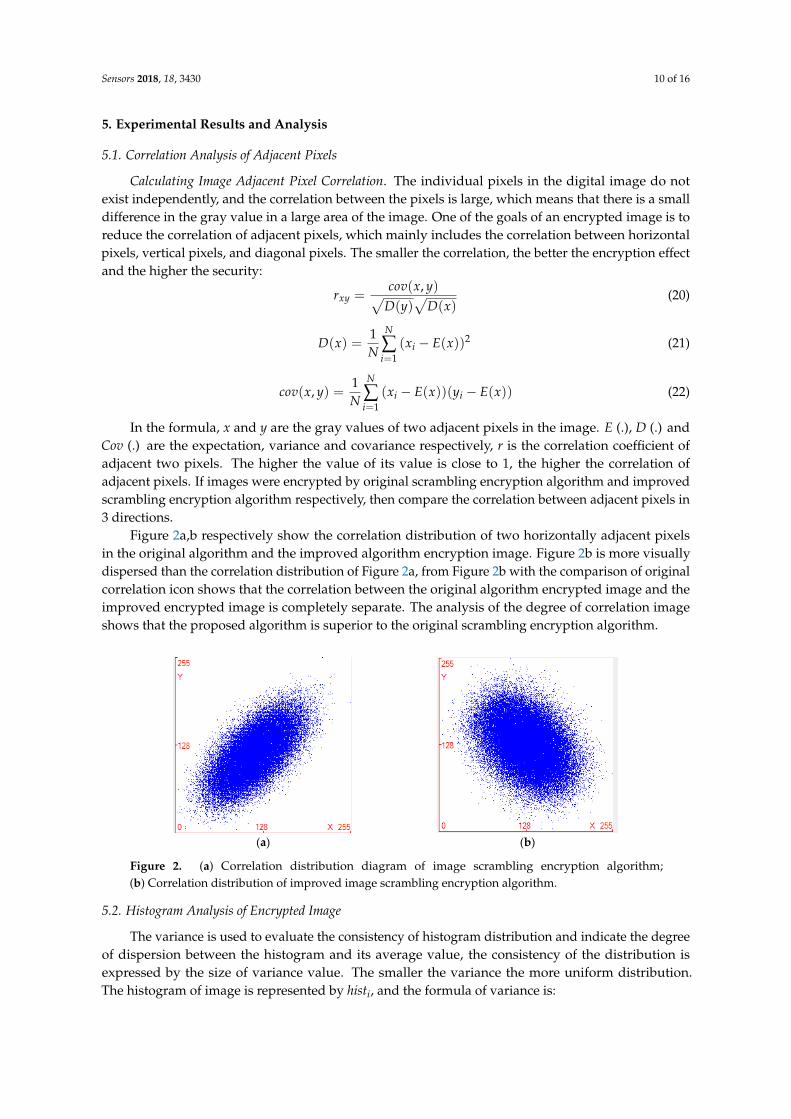
Figure 2a,b respectively show the correlation distribution of two horizontally adjacent pixelsin the original algorithm and the improved algorithm encryption image. Figure 2b is more visuallydispersed than the correlation distribution of Figure 2a, from Figure 2b with the comparison of originalcorrelation icon shows that the correlation between the original algorithm encrypted image and theimproved encrypted image is completely separate. The analysis of the degree of correlation imageshows that the proposed algorithm is superior to the original scrambling encryption algorithm.
Sensors 2018, 18, x FOR PEER REVIEW 10 of 16
( )( ) (x)xy
cov x, yr =D y D
(20)
2
1
1( ) ( ( ))N
ii
D x x E xN =
= − (21)
1
1( ) ( ( ))( ( ))N
i ii
cov x, y x E x y E xN =
= − − (22)
In the formula, x and y are the gray values of two adjacent pixels in the image. E (.), D (.) and Cov (.) are the expectation, variance and covariance respectively, r is the correlation coefficient of adjacent two pixels. The higher the value of its value is close to 1, the higher the correlation of adjacent pixels. If images were encrypted by original scrambling encryption algorithm and improved scrambling encryption algorithm respectively, then compare the correlation between adjacent pixels in 3 directions.
Figure 2a,b respectively show the correlation distribution of two horizontally adjacent pixels in the original algorithm and the improved algorithm encryption image. Figure 2b is more visually dispersed than the correlation distribution of Figure 2a, from Figure 2b with the comparison of original correlation icon shows that the correlation between the original algorithm encrypted image and the improved encrypted image is completely separate. The analysis of the degree of correlation image shows that the proposed algorithm is superior to the original scrambling encryption algorithm.
(a) (b)
Figure 2. (a) Correlation distribution diagram of image scrambling encryption algorithm; (b) Correlation distribution of improved image scrambling encryption algorithm.
5.2. Histogram Analysis of Encrypted Image
The variance is used to evaluate the consistency of histogram distribution and indicate the degree of dispersion between the histogram and its average value, the consistency of the distribution is expressed by the size of variance value. The smaller the variance the more uniform distribution. The histogram of image is represented by histi, and the formula of variance is:
2552
0
1 ( )256 i
iS hist aver
=
= − (23)
And the average (aver) is: 255
0
1256 i
iaver hist
=
= (24)
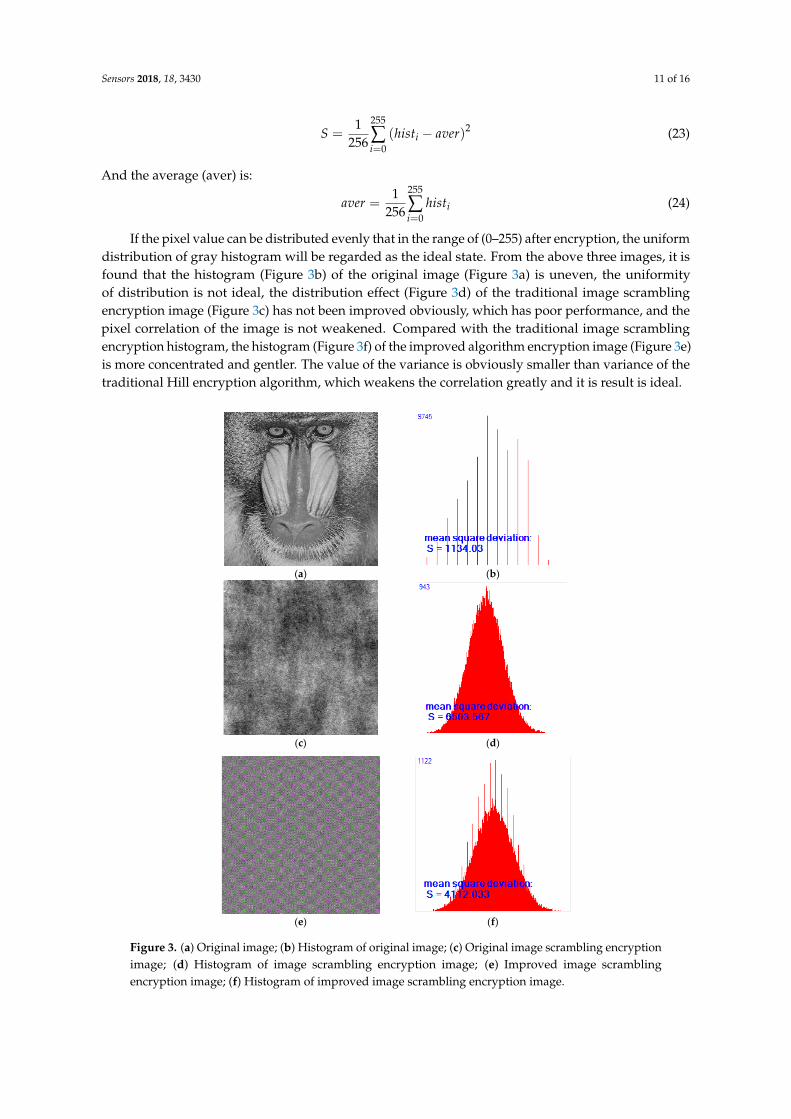
If the pixel value can be distributed evenly that in the range of (0–255) after encryption, the uniform distribution of gray histogram will be regarded as the ideal state. From the above three images, it is found that the histogram (Figure 3b) of the original image (Figure 3a) is uneven, the uniformity of distribution is not ideal, the distribution effect (Figure 3d) of the traditional image
Figure 2. (a) Correlation distribution diagram of image scrambling encryption algorithm;(b) Correlation distribution of improved image scrambling encryption algorithm.
5.2. Histogram Analysis of Encrypted Image
The variance is used to evaluate the consistency of histogram distribution and indicate the degreeof dispersion between the histogram and its average value, the consistency of the distribution isexpressed by the size of variance value. The smaller the variance the more uniform distribution.The histogram of image is represented by histi, and the formula of variance is:
Sensors 2018, 18, 3430 11 of 16
S =1
256
255
∑i=0
(histi − aver)2 (23)
And the average (aver) is:
aver =1
256
255
∑i=0
histi (24)
If the pixel value can be distributed evenly that in the range of (0–255) after encryption, the uniformdistribution of gray histogram will be regarded as the ideal state. From the above three images, it isfound that the histogram (Figure 3b) of the original image (Figure 3a) is uneven, the uniformityof distribution is not ideal, the distribution effect (Figure 3d) of the traditional image scramblingencryption image (Figure 3c) has not been improved obviously, which has poor performance, and thepixel correlation of the image is not weakened. Compared with the traditional image scramblingencryption histogram, the histogram (Figure 3f) of the improved algorithm encryption image (Figure 3e)is more concentrated and gentler. The value of the variance is obviously smaller than variance of thetraditional Hill encryption algorithm, which weakens the correlation greatly and it is result is ideal.
Sensors 2018, 18, x FOR PEER REVIEW 11 of 16
scrambling encryption image (Figure 3c) has not been improved obviously, which has poor performance, and the pixel correlation of the image is not weakened. Compared with the traditional image scrambling encryption histogram, the histogram (Figure 3f) of the improved algorithm encryption image (Figure 3e) is more concentrated and gentler. The value of the variance is obviously smaller than variance of the traditional Hill encryption algorithm, which weakens the correlation greatly and it is result is ideal.
(a) (b)
(c) (d)
(e) (f)
Figure 3. (a) Original image; (b) Histogram of original image; (c) Original image scrambling encryption image; (d) Histogram of image scrambling encryption image; (e) Improved image scrambling encryption image; (f) Histogram of improved image scrambling encryption image.
Figure 3. (a) Original image; (b) Histogram of original image; (c) Original image scrambling encryptionimage; (d) Histogram of image scrambling encryption image; (e) Improved image scramblingencryption image; (f) Histogram of improved image scrambling encryption image.

Sensors 2018, 18, 3430 12 of 16
5.3. Information Entropy and Peak Signal to Noise Ratio
Information Entropy is a concept that used to measure the amount of information in informationtheory, which contains information content of an image, the system is more orderly that informationentropy is lower. The information entropy of the image is:
H(m) = −L−1
∑i=0
p(mi)log2 p(mi),L−1
∑i=0
p(mi) = 0 (25)
where L and mi indicate that gray value is mi and description is L, Pmi indicates the probability of theappearance of the gray value. When the probability of gray value appears in the image is equally, it islargest that information entropy of the image, and its gray distribution is identical. When informationentropy is equal to 8 that is proved the random distribution of images is more ideal.
The Peak Signal-to-Noise Ratio is used to estimate the distortion of some lossy encryption. PNSRreflects the quality of the encryption algorithm, which indicates the change between the original pictureand the encrypted picture. Its calculation formula is:
PSNR = 10× lg
M× N × 2552
M−1∑
i=0
N−1∑
j=0(p(i, j)− c(i, j))2
(26)
In the formula, M and N represent the width and height of the image, and p(i,j) and c(i,j) are thepixel values of the original image and the decrypted image, respectively, and the smaller the value,the better the encryption quality. When p(i,j) and C(i,j) are the original picture and the decryptionpicture, respectively, the PSNR reflects the distortion of the encryption algorithm on the other hand.The larger the value, the smaller the algorithm’s amount distortion, and the encrypted the higher thequality [23–29].
Diffusion is an important feature in the encryption algorithm and as proposed by Shannon [30],an excellent encryption system must have good diffusivity. The meaning is that when a bit is changedin the original image, the encryption image will be changed in an unpredictable way. The diffusivityof the image encryption algorithm indicates that the output pixels of the encrypted image shouldbe dependent on the input pixels of the original image in a very complicated way, which can resistthe attacker’s analysis of the algorithm. Attackers usually make small changes to the original image,and then use the algorithms used as attackers to encrypt the original and modified images, and comparethe relationship between the original and the encrypted images by comparing two images. This kindof attack becomes a difference attack [31–33]. One pixel of the original image is modified by theattacker, looking at the changes in the result, it is possible for attacker to find a relationship between theoriginal image and the encrypted image. If a small change in the original image can cause significantchanges in the effects of diffusion and chaos, the efficiency of the differential attack is very low and theattack is invalid. In order to verify the influence of a pixel change in the entire encrypted image, twomeasurement methods are commonly used one is pixel change rate and the other is uniform averagechange intensity. Two encrypted images are represented by C1 and C2 respectively, only one pixel isdifferent in their corresponding original images, the gray values of images C1 and C2 at coordinates (i,j)are represented by C1(i,j) and C2(i,j), respectively. The uniform average change intensity UACI isdefined as:
UACI =
M−1∑
i=0
N−1∑
j=0|C1(i, j)− C1(i, j)|
255×M× N× 100% (27)
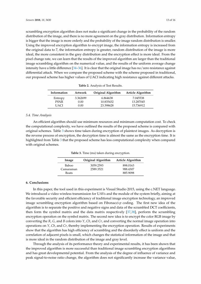
From Table 2, we can know the information entropy of the original image is equal to 3, the entropyof the traditional image scrambling encryption image is about 6. It is shown that the traditional image
Sensors 2018, 18, 3430 13 of 16
scrambling encryption algorithm does not make a significant change in the probability of the randomdistribution of the image, and there is no more agreement on the gray distribution. Information entropyis bigger that the image is more orderly and the probability of the image random distribution is smaller.Using the improved encryption algorithm to encrypt image, the information entropy is increased fromthe original data to 7, the information entropy is greater, random distribution of the image is moreideal, the more consistent in the grey distribution and the encryption effect is more ideal. From thepixel change rate, we can learn that the results of the improved algorithm are larger than the traditionalimage scrambling algorithm on the numerical value, and the results of the uniform average changeintensity have a little difference [34–36]. It is clear that the original image has no/zero resistance againstdifferential attack. When we compare the proposed scheme with the scheme proposed in traditional,our proposed scheme has higher values of UACI indicating high resistance against different attacks.
Table 2. Analysis of Test Results.
Information Artwork Original Algorithm Article Algorithm
Entropy 3.362699 6.864638 7.045538PSNR 0.00 10.835432 13.287045UACI 0.00 23.398628 15.736912
5.4. Time Analysis
An efficient algorithm should use minimum resources and minimum computation cost. To checkthe computational complexity, we have outlined the results of the proposed scheme is compared withoriginal schemes. Table 3 shows time taken during encryption of plaintext images. As decryption isthe reverse process of encryption, the decryption time is almost the same as the encryption time. It ishighlighted from Table 3 that the proposed scheme has less computational complexity when comparedwith original schemes.
Table 3. Time (ms) taken during encryption.
Image Original Algorithm Article Algorithm
Baboo 3059.2593 898.0163Camaraman 2589.3521 988.4307
Boats 885.9098
6. Conclusions
In this paper, the tool used in this experiment is Visual Studio 2015, using the c.NET language.We introduced a video wireless transmission for UAVs and the module of the system briefly, aiming atthe favorable security and efficient efficiency of traditional image encryption technology, an improvedimage scrambling encryption algorithm based on Fibonacci-p coding. The first new idea of thealgorithm is to separate the positive and negative signs and data of the scrambled DCT coefficients,then form the symbol matrix and the data matrix respectively [37,38], perform the scramblingencryption operation on the symbol matrix. The second new idea is to encrypt the color RGB image byconverting the R, G, and B colors into Y, Cb, and Cr, and converting the normal image operation intooperations on Y, Cb, and Cr, thereby implementing the encryption operation. Results of experimentsshow that the algorithm has high efficiency of scrambling and the disorderly effect is uniform and thecorrelation of adjacent pixels is small, which changes the statistical information of the image and thatis more ideal in the random distribution of the image and gray level.
Through the analysis of its performance theory and experimental results, it has been shown thatthe improved algorithm is more successful than traditional image scrambling encryption algorithmsand has great developmental potential. From the analysis of the degree of influence of variance andpeak signal-to-noise ratio change, the algorithm does not significantly increase the variance value,

Sensors 2018, 18, 3430 14 of 16
the value has been improved compared to the original algorithm but still does not achieve the desiredrange. Therefore, considering the improvement of this aspect will be the future direction.
Author Contributions: Conceptualization, J.D. and G.W.; Methodology, J.D.; Software, T.Y. and Y.L.; Validation,J.D. and G.W.; Formal Analysis, T.Y.; Investigation, J.D.; Data Curation, G.W.; Writing-Original Draft Preparation,J.D.; Writing-Review & Editing, J.D.
Funding: This work was supported in part by Research Project for FY2017 of International Association of MaritimeUniversities, China Postdoctoral Science Foundation under Grant 2015T80238, Natural Science Foundation ofChina under Grant 61771086 and 61401057, The Military Commission Equipment for the 13th Five-Year Field FundProject under Grant 61403120402, Dalian Outstanding Young Science and Technology Talents Foundation, NaturalScience Foundation of Liaoning Province under Grant 201602083, Science and Technology research program ofLiaoning under Grant L2014213, Dalian Science And Technology Project under Grant 2015A11GX018, ResearchFunds for the Central Universities 3132018144, 017180327 and 01760325. Dalian High-level Innovative TalentProject under Grant 2016RQ035.
Conflicts of Interest: The authors declare no conflict of interest.
Appendix A
The other two images that were used:
Sensors 2018, 18, x FOR PEER REVIEW 14 of 16
Author Contributions: Conceptualization, J.D. and G.W.; Methodology, J.D.; Software, T.Y. and Y.L.; Validation, J.D. and G.W.; Formal Analysis, T.Y.; Investigation, J.D.; Data Curation, G.W.; Writing-Original Draft Preparation, J.D.; Writing-Review & Editing, J.D.
Funding: This work was supported in part by Research Project for FY2017 of International Association of Maritime Universities, China Postdoctoral Science Foundation under Grant 2015T80238, Natural Science Foundation of China under Grant 61771086 and 61401057, The Military Commission Equipment for the 13th Five-Year Field Fund Project under Grant 61403120402, Dalian Outstanding Young Science and Technology Talents Foundation, Natural Science Foundation of Liaoning Province under Grant 201602083, Science and Technology research program of Liaoning under Grant L2014213, Dalian Science And Technology Project under Grant 2015A11GX018, Research Funds for the Central Universities 3132018144, 017180327 and 01760325. Dalian High-level Innovative Talent Project under Grant 2016RQ035.
Conflicts of Interest: The authors declare no conflict of interest.
Appendix A
The other two images that were used:
Cameraman Boats
References
1. Ye, G. Image scrambling encryption algorithm of pixel bit based on chaos map. Pattern Recogn. Lett. 2010, 31, 347–354.
2. Li, C.; Lin, D.; Lu, J. Cryptanalyzing an Image-Scrambling Encryption Algorithm of Pixel Bits. IEEE Multimed. 2017, 24, 64–71.
3. Tang, Z.J. Image Scrambling Encryption Algorithm Based on Chaotic Mapping. J. Changsha Aeronaut. Vocat. Tech. Coll. 2017, 17, doi:10.13829/j.cnki.issn.1671-9654.2017.02.022. (In Chinese)
4. Xu, L.; Gou, X.; Li, Z.; Li, J. A novel chaotic image encryption algorithm using block scrambling and dynamic index based diffusion. Opt. Lasers Eng. 2017, 91, 41–52.
5. Chen, Y.X. Image encryption algorithm based on scrambling switching decision mechanism harmony search. J. Shenyang Univ. Technol. 2017, 39, 333–339, doi:10.7688/j.issn.1000-1646.2017.03.17. (In Chinese)
6. Liu, J.; Yang, D.; Zhou, H.; Chen, S. A new image encryption algorithm based on improved logistic map and block-mod algorithm. In Proceedings of the 2017 IEEE 2nd Advanced Information Technology, Electronic and Automation Control Conference (IAEAC), Chongqing, China, 25–26 March 2017; pp. 2314–2319.
7. Tang, R.; Duan, J.; Deng, H. Image encryption algorithm based on Logistic chaotic sequence and DES. J. Comput. Appl. 2017. Available online: http://en.cnki.com.cn/Article_en/CJFDTOTAL-JSJY2017S1019.htm (accessed on 6 October 2018).
8. Luo, H.; Ge, B.; Wang, J.; Wu, B. Dynamic self-feedback chaotic system image encryption based on neural network scrambling image. J. Image Graph. 2018, 23, doi:10.11834 /jig.170464. (In Chinese)
9. Zeng, L.; Liu, R.; Zhang, L.Y.; Liu, Y.; Wong, K.W. Cryptanalyzing an image encryption algorithm based on scrambling and Veginère cipher. Multimed. Tools Appl. 2016, 75, 5439–5453.
10. Cui, Y.; Ding, G. Chaotic image encryption algorithm based on single image local scrambling and dynamic feedback diffusion. Telecommun. Sci. 2016, doi:10.11959/j.issn.1000-0801.2016286. (In Chinese)
References
1. Ye, G. Image scrambling encryption algorithm of pixel bit based on chaos map. Pattern Recogn. Lett. 2010, 31,347–354. [CrossRef]
2. Li, C.; Lin, D.; Lu, J. Cryptanalyzing an Image-Scrambling Encryption Algorithm of Pixel Bits. IEEE Multimed.2017, 24, 64–71. [CrossRef]
3. Tang, Z.J. Image Scrambling Encryption Algorithm Based on Chaotic Mapping. J. Changsha Aeronaut. Vocat.Tech. Coll. 2017, 17. (In Chinese) [CrossRef]
4. Xu, L.; Gou, X.; Li, Z.; Li, J. A novel chaotic image encryption algorithm using block scrambling and dynamicindex based diffusion. Opt. Lasers Eng. 2017, 91, 41–52. [CrossRef]
5. Chen, Y.X. Image encryption algorithm based on scrambling switching decision mechanism harmony search.J. Shenyang Univ. Technol. 2017, 39, 333–339. (In Chinese) [CrossRef]
6. Liu, J.; Yang, D.; Zhou, H.; Chen, S. A new image encryption algorithm based on improved logistic map andblock-mod algorithm. In Proceedings of the 2017 IEEE 2nd Advanced Information Technology, Electronicand Automation Control Conference (IAEAC), Chongqing, China, 25–26 March 2017; pp. 2314–2319.
7. Tang, R.; Duan, J.; Deng, H. Image encryption algorithm based on Logistic chaotic sequence and DES.J. Comput. Appl. 2017. Available online: http://en.cnki.com.cn/Article_en/CJFDTOTAL-JSJY2017S1019.htm(accessed on 6 October 2018).
8. Luo, H.; Ge, B.; Wang, J.; Wu, B. Dynamic self-feedback chaotic system image encryption based on neuralnetwork scrambling image. J. Image Graph. 2018, 23. (In Chinese) [CrossRef]
9. Zeng, L.; Liu, R.; Zhang, L.Y.; Liu, Y.; Wong, K.W. Cryptanalyzing an image encryption algorithm based onscrambling and Veginère cipher. Multimed. Tools Appl. 2016, 75, 5439–5453. [CrossRef]

Sensors 2018, 18, 3430 15 of 16
10. Cui, Y.; Ding, G. Chaotic image encryption algorithm based on single image local scrambling and dynamicfeedback diffusion. Telecommun. Sci. 2016. (In Chinese) [CrossRef]
11. Xie, G.; Yang, B. Computer Chaos Image Encryption Algorithm Based on Bit Scrambling. Comput. Eng.2017. Available online: http://en.cnki.com.cn/Article_en/CJFDTOTAL-JSJC201707031.htm (accessed on 6October 2018).
12. Xie, G.B.; Wang, T. A Novel Hyperchaotic Image Encryption Algorithm Based on Bit Scrambling.Microelectron. Comput. 2016, 33. (In Chinese) [CrossRef]
13. Elhoseny, M.; Farouk, A.; Batle, J.; Shehab, A.; Hassanien, A.E. Secure Image Processingand Transmission Schema in Cluster-Based Wireless Sensor Network. 2017. Available online:https://www.igi-global.com/chapter/secure-image-processing-and-transmission-schema-in-cluster-based-wireless-sensor-network/180983 (accessed on 6 October 2018).
14. Wang, Y.; Wang, D.; Zhang, X.; Chen, J.; Li, Y. Energy-Efficient Image Compressive Transmission for WirelessCamera Networks. IEEE Sens. J. 2016, 16, 3875–3886. [CrossRef]
15. Senthamilselvan, K.; Dhevi, L. Wireless Transmission Based Image Quality Analysis Using Uni-Level HaarWavelet Transform. Circuits Syst. 2016, 7, 1816–1821. [CrossRef]
16. Ziaullah, M.; Shetty, P.; Kamal, S. Image feature based authentication and digital signature for wirelessdata transmission. In Proceedings of the 2016 International Conference on Computer Communication andInformatics (ICCCI), Coimbatore, India, 7–9 January 2016.
17. Ali, H.S.; Atallah, A.M.; Abdalla, M.I. An Efficient Source–Channel Coding for Wireless Image TransmissionOver Underwater Acoustic Channel. Wirel. Pers. Commun. 2017, 96, 1–12. [CrossRef]
18. Hayami, H.; Takehara, H.; Nagata, K.; Haruta, M.; Noda, T.; Sasagawa, K.; Tokuda, T.; Ohta, J. Wirelessimage-data transmission from an implanted image sensor through a living mouse brain by intra bodycommunication. Jpn. J. Appl. Phys. 2016, 55, 04EM03. [CrossRef]
19. Salwe, S.S.; Naik, K.K. Discrete image data transmission in heterogeneous wireless network using verticalhandover mechanism. IET Image Process. 2017, 11, 550–558. [CrossRef]
20. Rahman, A.M.A. Color Image Transmission on MIMO MC-CDMA Wireless Communication System.2016. Available online: https://www.lap-publishing.com/catalog/details//store/gb/book/978-3-659-88252-4/color-image-transmission-on-mimo-mc-cdma-wireless-communication-system (accessed on 6October 2018).
21. Zhu, R.B. Optical Wireless Transmission under Static Image Information Hiding Method Exhibits theSimulation. Comput. Simul. 2017, 34, 187–190. (In Chinese)
22. Zhang, L.N. A High-speed Image Two-Scrambling Encryption Algorithm Based on Self-Generating UnitMatrix Model m. Sci. Technol. Eng. 2013, 9, 48.
23. Niu, Y.J.; Zhao, Y.F. New Image Scrambling Hiding Algorithm Based on Chaotic Proliferation Encryption.Comput. Modern. 2013. Available online: http://en.cnki.com.cn/Article_en/CJFDTOTAL-JYXH201306027.htm (accessed on 6 October 2018).
24. Fan, Y.; Liu, D. Digital Image Random Scrambling Encryption Algorithm Based on Chaotic System. J. AnyangInst. Technol. 2013. (In Chinese) [CrossRef]
25. Liu, Z.; Li, S.; Liu, W.; Wang, Y.; Liu, S. Image encryption algorithm by using fractional Fourier transformand pixel scrambling operation based on double random phase encoding. Opt. Lasers Eng. 2013, 51, 8–14.[CrossRef]
26. Zhang, Y. Cryptanalysis of an Image Encryption Algorithm Based on Chaotic Modulation of Arnold DualScrambling and DNA Computing. Adv. Sci. Focus 2014, 2, 67–82. [CrossRef]
27. Yang, B.; Deng, C.; Wu, P.; Xi, J.; Shi, L. Image encryption algorithm based on two-one-dimension logisticchaotic inter-scrambling systems and m-sequence. In Proceedings of the 2014 IEEE 5th InternationalConference on Software Engineering and Service Science, Beijing, China, 27–29 June 2014; pp. 521–524.
28. Sivakumar, T.; Venkatesan, R. A Novel Image Encryption Using Calligraphy Based Scan Method and RandomNumber. KSII Trans. Internet Inf. Syst. 2015, 9, 2317–2337.
29. Lai, Q.M. Validation of Image Encryption Algorithm Based on Arnold Transform. Electron. Qual. 2015.Available online: http://en.cnki.com.cn/Article_en/CJFDTotal-DZZN201506010.htm (accessed on 8 October2018).
30. Wang, K.; Ye, F. Improved Encryption Algorithm of Images Based on Three-Dimensional Chaos. Int. J. Cogn.Inform. Nat. Intell. 2015, 9, 73–83. [CrossRef]

Sensors 2018, 18, 3430 16 of 16
31. Kuang, L.; Yang, L.; Feng, J.; Dong, M. Secure Tensor Decomposition Using Fully Homomorphic EncryptionScheme. IEEE Trans. Cloud Comput. 2018, 6, 868–878. [CrossRef]
32. Ahmad, J.; Hwang, S.O. A secure image encryption scheme based on chaotic maps and affine transformation.Multimed. Tools Appl. 2016, 75, 13951–13976. [CrossRef]
33. Wu, J.; Ota, K.; Dong, M.; Li, J.; Wang, H. Big Data Analysis-Based Security Situational Awareness for SmartGrid. J. Intell. Fuzzy Syst. 2017, 33, 3753–3765. [CrossRef]
34. Saval-Calvo, M.; Azorin-Lopez, J.; Fuster-Guillo, A.; Garcia-Rodriguez, J.; Orts-Escolano, S.; Garcia-Garcia, A.Evaluation of sampling method effects in 3D non-rigid registration. Neural Comput. Appl. 2017, 28, 953–967.[CrossRef]
35. Tao, M.; Ota, K.; Dong, M.; Qian, Z. AccessAuth: Capacity-aware security access authentication infederated-IoT-enabled V2G networks. J. Parallel Distrib. Comput. 2018, 118, 107–117. [CrossRef]
36. Enayatifar, R.; Abdullah, A.H.; Isnin, I.F. Chaos-based image encryption using a hybrid genetic algorithmand a DNA sequence. Opt. Lasers Eng. 2014, 56, 83–93. [CrossRef]
37. Khan, F.A.; Ahmed, J.; Khan, J.S.; Ahmad, J.; Khan, M.A. A novel image encryption based on Lorenz equation,Gingerbreadman chaotic map and S8 permutation. J. Intell. Fuzzy Syst. 2017, 33, 1–13. [CrossRef]
38. Liu, X.; Liu, Y.; Xiong, N.; Zhang, N.; Liu, A.; Shen, H.; Huang, C. Construction of Large-Scale Low CostDeliver Infrastructure using Vehicular Networks. IEEE Access 2018, 6, 21482–21497. [CrossRef]
© 2018 by the authors. Licensee MDPI, Basel, Switzerland. This article is an open accessarticle distributed under the terms and conditions of the Creative Commons Attribution(CC BY) license (http://creativecommons.org/licenses/by/4.0/).