wireless pneumatic thermostat- wpt-800 series …cypressenvirosystems.com/files/pdf/910-00005-01...
TRANSCRIPT
WPT Installation Manual
Document No. 910-00005-01 rev 09
Wireless Pneumatic Thermostat- WPT-800 Series
Page 1 of 14
1. Overview
Cypress Envirosystems Wireless Pneumatic Thermostat (WPT) retrofits existing Pneumatic
Thermostats in minutes to deliver Direct Digital Control (DDC) like zone control functionality in
a fraction of a time and cost without disturbing the occupants.
The WPT enables remote monitoring of zone temperature, branch pressure, remote control of
setpoints, and programmable setback or setup of the pneumatic HVAC systems. It also
enables integration with utility Demand Response programs.
The WPT either works as a standalone system or integrates with the existing Building
Management System via BACnet/IP. As a result, the WPT helps building owner and tenants
to save energy, improve comfort, and reduce the maintenance cost of the legacy pneumatic
HVAC systems.
1.1 Parts Included
The parts included in the WPT- 800 Series kit are as follows:
WPT
Universal wall bracket
Mounting screws (x2)
CR123 Batteries (x2)
1.2 Prerequisites for Installation
The WPT relies on a wireless network for communication. Before installing the WPT's, the
wireless network has to be set up, as per the WPT Network Planning Guide (Document no.
910-00006-01). It must also be ensured that the following tasks are completed before
proceeding to WPT installation:
Installation of WPT Web Server and Hub
Installation of WPT Repeaters
Assigning the network ID
Assigning node ID‟s (Each WPT requires a unique node ID to identify itself within the
network).

WPT Installation Manual
Document No. 910-00005-01 rev 09
Page 2 of 14
1.3 Special Tools Needed
The special hand tools needed for WPT installation are the following:
Philips head screw driver
1/16” hex Allen key
2mm hex Allen key
2. WPT Installation
Installation of the WPT consists of the following:
Mounting the WPT on the wall
Configuring the WPT
Calibrating the WPT
2.1 Mounting the WPT
The mounting of WPT consists of the following:
Removing existing thermostat
Installing WPT
2.1.1 Removing Existing Thermostat
To remove the existing thermostat:
1. Remove the external cover, if any.
2. Locate and remove the mounting screws and carefully withdraw the unit from the wall along
with the pneumatic tubes attached.
3. Detach the old thermostat unit from the air pipes carefully.
In a 2-pipe system, note the positions of branch and main pipes.
WPT Installation Manual
Document No. 910-00005-01 rev 09
Page 3 of 14
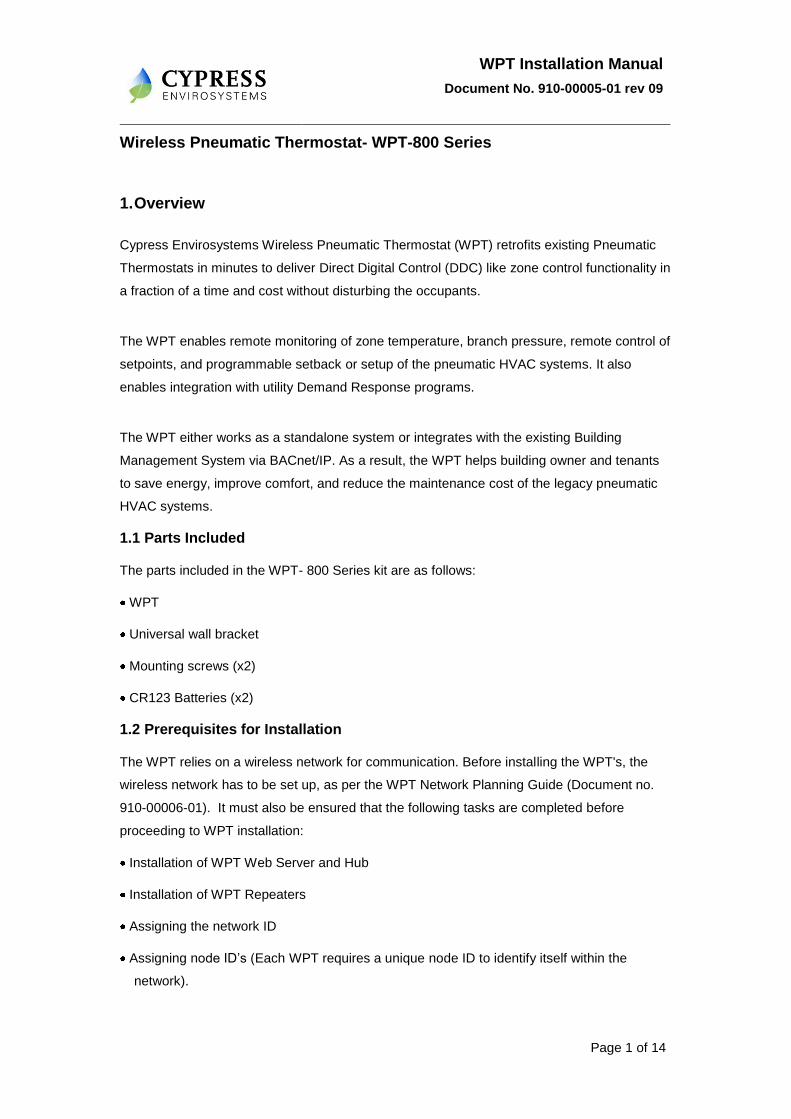
Warning !
2.1.2 ESD Handling Precautions
The WPT contains ESD sensitive circuit cards and components.
Great care must be exercised while handling WPT with the cover open.
Do not touch any of the circuit boards with fingers or any part of the body.
Touching the circuit boards may cause the unit to fail due to Electrostatic discharge.
Hold and handle the unit as shown in figure 1, using the external bottom plastic cover
as the support.
Figure 1- Handling WPT
WPT Installation Manual
Document No. 910-00005-01 rev 09
Page 4 of 14
2.1.3 Installing WPT
The WPT is installed in the existing thermostat location using a universal wall bracket
provided with the WPT kit. To install the WPT:
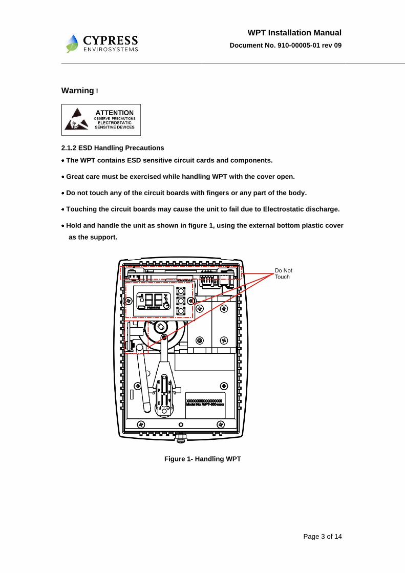
1. Remove the universal wall mounting bracket from the WPT.
This can be done by unscrewing the two captive screws on the bottom of the WPT, as
shown in figure 2.
Figure 2- Removing Universal Wall Bracket
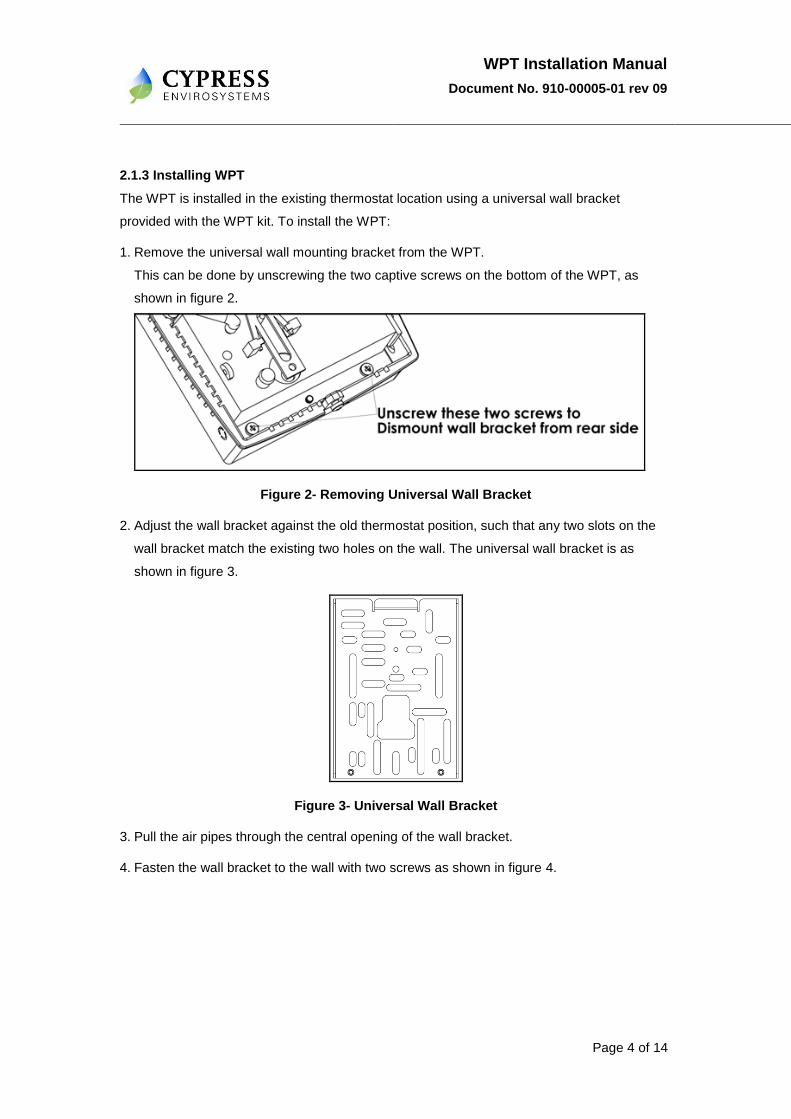
2. Adjust the wall bracket against the old thermostat position, such that any two slots on the
wall bracket match the existing two holes on the wall. The universal wall bracket is as
shown in figure 3.
Figure 3- Universal Wall Bracket
3. Pull the air pipes through the central opening of the wall bracket.
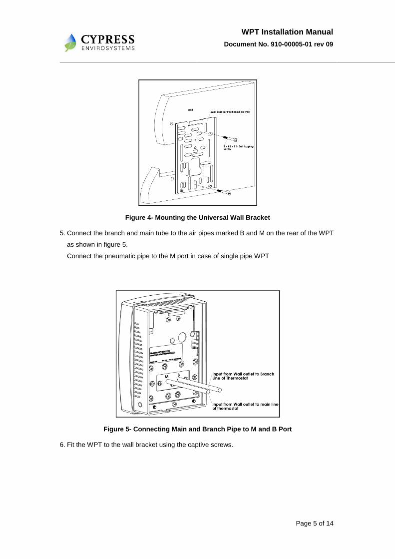
4. Fasten the wall bracket to the wall with two screws as shown in figure 4.
WPT Installation Manual
Document No. 910-00005-01 rev 09
Page 5 of 14
Figure 4- Mounting the Universal Wall Bracket
5. Connect the branch and main tube to the air pipes marked B and M on the rear of the WPT
as shown in figure 5.
Connect the pneumatic pipe to the M port in case of single pipe WPT
Figure 5- Connecting Main and Branch Pipe to M and B Port
6. Fit the WPT to the wall bracket using the captive screws.
WPT Installation Manual
Document No. 910-00005-01 rev 09
Page 6 of 14
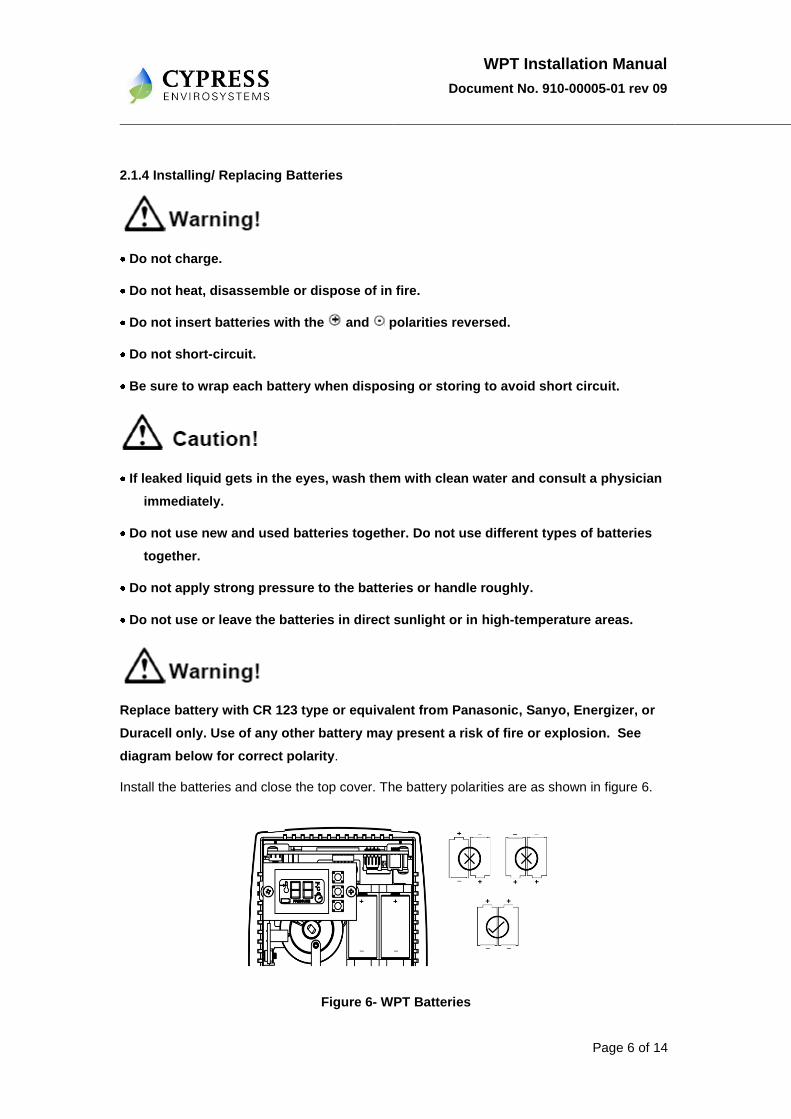
2.1.4 Installing/ Replacing Batteries
Do not charge.
Do not heat, disassemble or dispose of in fire.
Do not insert batteries with the and polarities reversed.
Do not short-circuit.
Be sure to wrap each battery when disposing or storing to avoid short circuit.
If leaked liquid gets in the eyes, wash them with clean water and consult a physician
immediately.
Do not use new and used batteries together. Do not use different types of batteries
together.
Do not apply strong pressure to the batteries or handle roughly.
Do not use or leave the batteries in direct sunlight or in high-temperature areas.
Replace battery with CR 123 type or equivalent from Panasonic, Sanyo, Energizer, or
Duracell only. Use of any other battery may present a risk of fire or explosion. See
diagram below for correct polarity.
Install the batteries and close the top cover. The battery polarities are as shown in figure 6.
Figure 6- WPT Batteries
WPT Installation Manual
Document No. 910-00005-01 rev 09
Page 7 of 14
2.2 Configuring the WPT
The WPT has to be configured with a valid network ID and node ID for the WPT to be
operational. The network ID is a single digit number while the node ID is a four digit number.
The four digit node ID is displayed in groups of two (D2, D1 together and D4, D3 together).
D4 D3 D2 D1
Figure 7- WPT Node ID Digits
Before configuring the WPT, insert the batteries in the holder and press any key. The system
will switch on and perform initialization. During initialization and every time when the WPT
starts a discovery process, a “dy” symbol is displayed on the LCD for a few seconds. During
this period the stat is attempting to discover its nearest RWALs and HUB. This process
should not be disturbed. The operator must wait for the “dy” to disappear from the LCD before
commencing any operation. After initialization, the LCD displays either E0 or current
temperature. The WPT is now ready for the configuration of the network ID and the node ID.
To configure the network ID and the node IDs, perform the following:
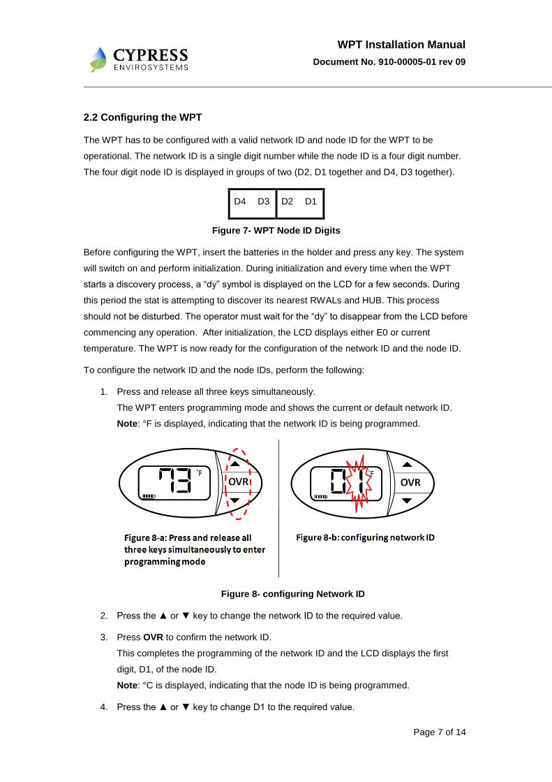
1. Press and release all three keys simultaneously.
The WPT enters programming mode and shows the current or default network ID.
Note: °F is displayed, indicating that the network ID is being programmed.
Figure 8- configuring Network ID
2. Press the ▲ or ▼ key to change the network ID to the required value.
3. Press OVR to confirm the network ID.
This completes the programming of the network ID and the LCD displays the first
digit, D1, of the node ID.
Note: °C is displayed, indicating that the node ID is being programmed.
4. Press the ▲ or ▼ key to change D1 to the required value.
WPT Installation Manual
Document No. 910-00005-01 rev 09
Page 8 of 14
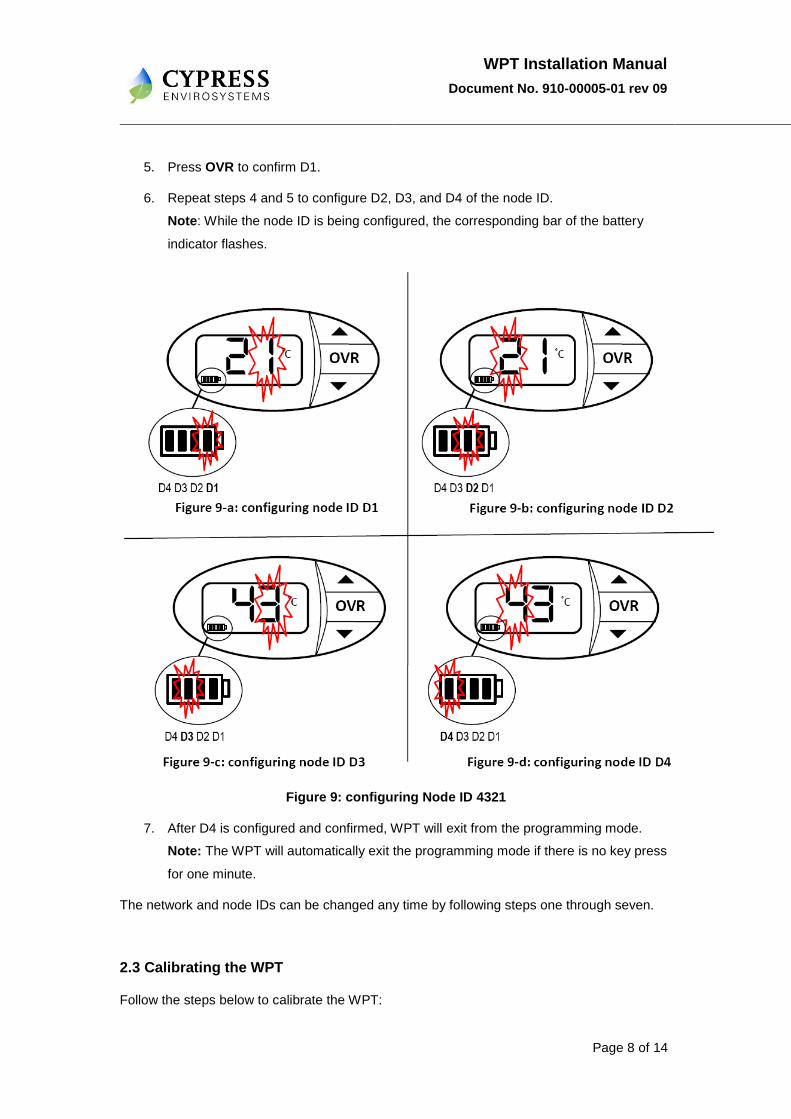
5. Press OVR to confirm D1.
6. Repeat steps 4 and 5 to configure D2, D3, and D4 of the node ID.
Note: While the node ID is being configured, the corresponding bar of the battery
indicator flashes.
Figure 9: configuring Node ID 4321
7. After D4 is configured and confirmed, WPT will exit from the programming mode.
Note: The WPT will automatically exit the programming mode if there is no key press
for one minute.
The network and node IDs can be changed any time by following steps one through seven.
2.3 Calibrating the WPT
Follow the steps below to calibrate the WPT:
WPT Installation Manual
Document No. 910-00005-01 rev 09
Page 9 of 14
1. Remove the front cover of WPT.
2. Make sure that the WPT is acclimatized to the ambient temperature. This can take 5
to 10 minutes after attachment to the wall. The Bi-metallic spring is very sensitive to
body heat. Keep hands and breathe away from WPT to minimize calibration error.
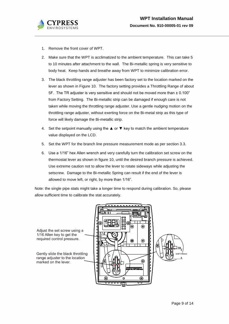
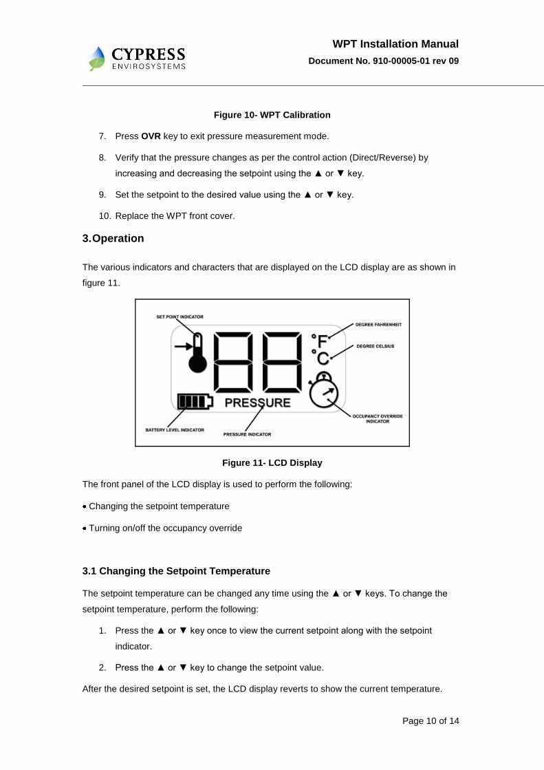
3. The black throttling range adjuster has been factory set to the location marked on the
lever as shown in Figure 10. The factory setting provides a Throttling Range of about
5F. The TR adjuster is very sensitive and should not be moved more than ± 0.100”
from Factory Setting. The Bi-metallic strip can be damaged if enough care is not
taken while moving the throttling range adjuster. Use a gentle nudging motion on the
throttling range adjuster, without exerting force on the Bi-metal strip as this type of
force will likely damage the Bi-metallic strip.
4. Set the setpoint manually using the ▲ or ▼ key to match the ambient temperature
value displayed on the LCD.
5. Set the WPT for the branch line pressure measurement mode as per section 3.3.
6. Use a 1/16” hex Allen wrench and very carefully turn the calibration set screw on the
thermostat lever as shown in figure 10, until the desired branch pressure is achieved.
Use extreme caution not to allow the lever to rotate sideways while adjusting the
setscrew. Damage to the Bi-metallic Spring can result if the end of the lever is
allowed to move left, or right, by more than 1/16”.
Note: the single pipe stats might take a longer time to respond during calibration. So, please
allow sufficient time to calibrate the stat accurately.
WPT Installation Manual
Document No. 910-00005-01 rev 09
Page 10 of 14
Figure 10- WPT Calibration
7. Press OVR key to exit pressure measurement mode.
8. Verify that the pressure changes as per the control action (Direct/Reverse) by
increasing and decreasing the setpoint using the ▲ or ▼ key.
9. Set the setpoint to the desired value using the ▲ or ▼ key.
10. Replace the WPT front cover.
3. Operation
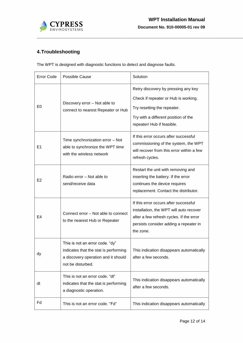
The various indicators and characters that are displayed on the LCD display are as shown in
figure 11.
Figure 11- LCD Display
The front panel of the LCD display is used to perform the following:
Changing the setpoint temperature
Turning on/off the occupancy override
3.1 Changing the Setpoint Temperature
The setpoint temperature can be changed any time using the ▲ or ▼ keys. To change the
setpoint temperature, perform the following:
1. Press the ▲ or ▼ key once to view the current setpoint along with the setpoint
indicator.
2. Press the ▲ or ▼ key to change the setpoint value.
After the desired setpoint is set, the LCD display reverts to show the current temperature.

WPT Installation Manual
Document No. 910-00005-01 rev 09
Page 11 of 14
3.2 Turning ON/OFF the Occupancy Override
To change the occupancy override, perform the following:
1. Press the OVR key to activate the occupancy override.
The LCD display flashes the override duration in hours.
2. Press the ▲ or ▼ key to change the override duration to desired value.
During the override duration, the LCD displays the Occupancy Override indicator.
3.3 Measuring the Branch Line Pressure
To measure the branch line pressure, perform the following:
1. Press the ▼ key and OVR key together and then release them.
Note: The display shows „dt‟.
2. Press OVR twice. The LCD displays the branch pressure in PSI along with
PRESSURE indicator.
3. Press OVR to exit.
WPT Installation Manual
Document No. 910-00005-01 rev 09
Page 12 of 14
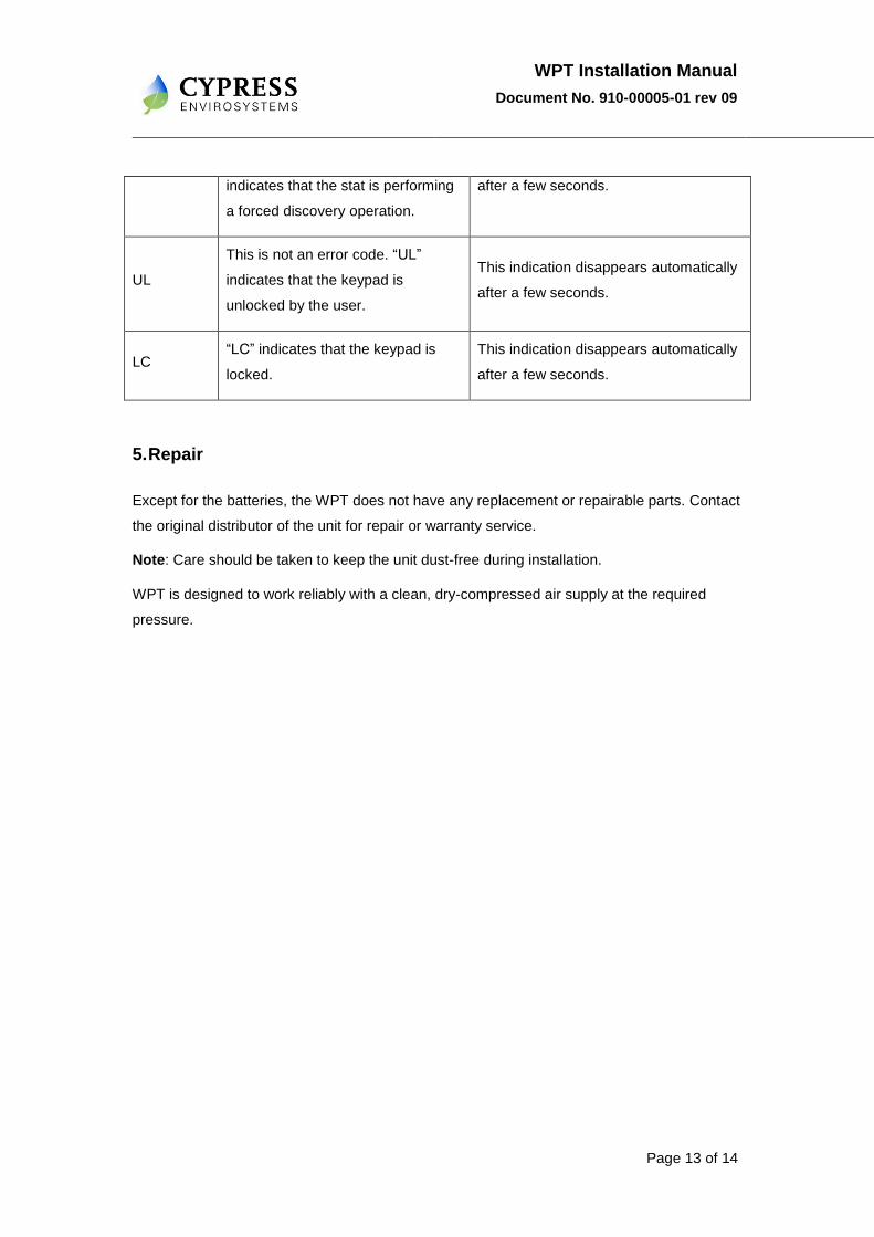
4. Troubleshooting
The WPT is designed with diagnostic functions to detect and diagnose faults.
Error Code Possible Cause Solution
E0 Discovery error – Not able to
connect to nearest Repeater or Hub
Retry discovery by pressing any key
Check if repeater or Hub is working.
Try resetting the repeater.
Try with a different position of the
repeater/ Hub if feasible.
E1
Time synchronization error – Not
able to synchronize the WPT time
with the wireless network
If this error occurs after successful
commissioning of the system, the WPT
will recover from this error within a few
refresh cycles.
E2 Radio error – Not able to
send/receive data
Restart the unit with removing and
inserting the battery. If the error
continues the device requires
replacement. Contact the distributor.
E4 Connect error – Not able to connect
to the nearest Hub or Repeater
If this error occurs after successful
installation, the WPT will auto recover
after a few refresh cycles. If the error
persists consider adding a repeater in
the zone.
dy
This is not an error code. “dy”
indicates that the stat is performing
a discovery operation and it should
not be disturbed.
This indication disappears automatically
after a few seconds.
dt
This is not an error code. “dt”
indicates that the stat is performing
a diagnostic operation.
This indication disappears automatically
after a few seconds.
Fd This is not an error code. “Fd” This indication disappears automatically
WPT Installation Manual
Document No. 910-00005-01 rev 09
Page 13 of 14
indicates that the stat is performing
a forced discovery operation.
after a few seconds.
UL
This is not an error code. “UL”
indicates that the keypad is
unlocked by the user.
This indication disappears automatically
after a few seconds.
LC “LC” indicates that the keypad is
locked.
This indication disappears automatically
after a few seconds.
5. Repair
Except for the batteries, the WPT does not have any replacement or repairable parts. Contact
the original distributor of the unit for repair or warranty service.
Note: Care should be taken to keep the unit dust-free during installation.
WPT is designed to work reliably with a clean, dry-compressed air supply at the required
pressure.

WPT Installation Manual
Document No. 910-00005-01 rev 09
Page 14 of 14
6. Technical Specification
The technical specifications of the WPT are as follows:
Action Direct/ Reverse Acting
Number of pipes Single/ Dual pipe
Setpoint Temperature Range 55 ºF to 85 ºF
Air connections 3/32 in (2.5mm) ID tube
Maximum Operating Pressure 25 psi (170 kPa)
Airflow Usage 0.011 scfm (5.2 mL/s)
Sensitivity Factory Adjusted to 2.0 - 2.5 PSI/F
Operating Frequency Band 2.4 GHz ISM Band
Battery Life More than 2 years*
Operating Condition 32 to 122 ºF (0 to 50 ºC); 95%RH Max, Noncondensing
Storage Condition -40 to 122 ºF (-40 to 50 ºC); 95%RH Max, Noncondensing
Dimensions
Length – 141mm(5.6”)
Width – 28.5 mm(1.2”)
Depth – 103.5mm(4.1”)
* With four setpoint changes per day.
Cypress Envirosystems
198 Champion Court
San Jose, CA-95134, US
Phone: +1(408)943-2800