(without nav) (with color screen) dash disassembly 99...
TRANSCRIPT
METRA. The World’s best kits.® metraonline.com © COPYRIGHT 2017 METRA ELECTRONICS CORPORATION
REV.
12/
14/2
017
INS
T99-
7627
HG
CAUTION: Metra recommends disconnecting the negative battery terminal before beginning any installation, unless the vehicle manufacturer recommends against so. Please check with your local Dealership for more information. All accessories, switches, climate controls panels, and especially air bag indicator lights must be connected before reconnecting the battery or cycling the ignition. Also, do not remove the factory radio with the key in the on position, or the vehicle running. It would be best to remove the key from the ignition and then wait a few seconds before removing the factory radio.
Installation instructions for part 99-7627HG U.S. PATENT # D789,351
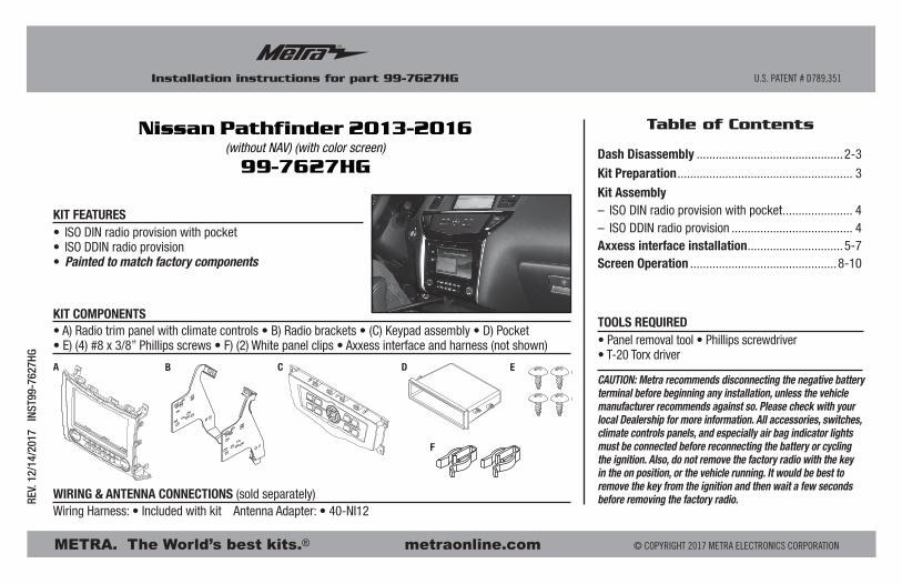
• ISO DIN radio provision with pocket• ISO DDIN radio provision• Painted to match factory components
• A) Radio trim panel with climate controls • B) Radio brackets • (C) Keypad assembly • D) Pocket • E) (4) #8 x 3/8” Phillips screws • F) (2) White panel clips • Axxess interface and harness (not shown)
KIT FEATURES
KIT COMPONENTS
WIRING & ANTENNA CONNECTIONS (sold separately)Wiring Harness: • Included with kit Antenna Adapter: • 40-NI12
• Panel removal tool • Phillips screwdriver • T-20 Torx driver
TOOLS REQUIRED
Nissan Pathfinder 2013-2016(without NAV) (with color screen)
99-7627HG
A DC E
F
B
Dash Disassembly ..............................................2-3
Kit Preparation ....................................................... 3
Kit Assembly– ISO DIN radio provision with pocket ...................... 4– ISO DDIN radio provision ...................................... 4Axxess interface installation ..............................5-7Screen Operation ..............................................8-10
Table of Contents
99-7627HG
2
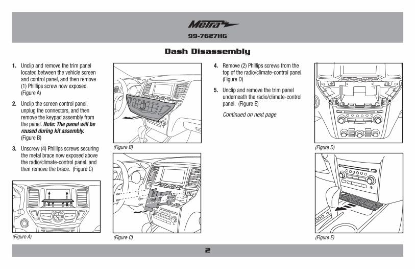
Dash Disassembly
1. Unclip and remove the trim panel located between the vehicle screen and control panel, and then remove (1) Phillips screw now exposed. (Figure A)
2. Unclip the screen control panel, unplug the connectors, and then remove the keypad assembly from the panel. Note: The panel will be reused during kit assembly. (Figure B)
3. Unscrew (4) Phillips screws securing the metal brace now exposed above the radio/climate-control panel, and then remove the brace. (Figure C)
4. Remove (2) Phillips screws from the top of the radio/climate-control panel. (Figure D)
5. Unclip and remove the trim panel underneath the radio/climate-control panel. (Figure E)
Continued on next page
(Figure A) (Figure E)
(Figure D)(Figure B)
(Figure C)
99-7627HG
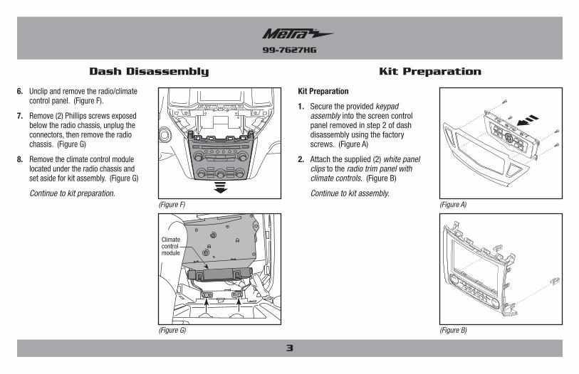
6. Unclip and remove the radio/climate control panel. (Figure F).
7. Remove (2) Phillips screws exposed below the radio chassis, unplug the connectors, then remove the radio chassis. (Figure G)
8. Remove the climate control module located under the radio chassis and set aside for kit assembly. (Figure G)
Continue to kit preparation.
3
Kit PreparationDash Disassembly
Kit Preparation
1. Secure the provided keypad assembly into the screen control panel removed in step 2 of dash disassembly using the factory screws. (Figure A)
2. Attach the supplied (2) white panel clips to the radio trim panel with climate controls. (Figure B)
Continue to kit assembly.(Figure F) (Figure A)
(Figure G) (Figure B)
Climate control module
99-7627HG
4
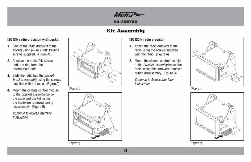
Kit Assembly
ISO DIN radio provision with pocket
1. Secure the radio brackets to the pocket using (4) #8 x 3/8” Phillips screws supplied. (Figure A)
2. Remove the metal DIN sleeve and trim ring from the aftermarket radio.
3. Slide the radio into the pocket/bracket assembly using the screws supplied with the radio. (Figure A)
4. Mount the climate control module to the bracket assembly below the radio and pocket, using the hardware removed during disassembly. (Figure B)
Continue to Axxess Interface Installation
ISO DDIN radio provision
1. Attach the radio brackets to the radio using the screws supplied with the radio. (Figure A)
2. Mount the climate control module to the bracket assembly below the radio, using the hardware removed during disassembly. (Figure B)
Continue to Axxess Interface Installation
(Figure A)
(Figure B)
(Figure A)
(Figure B)
99-7627HG
5
Axxess Interface Installation
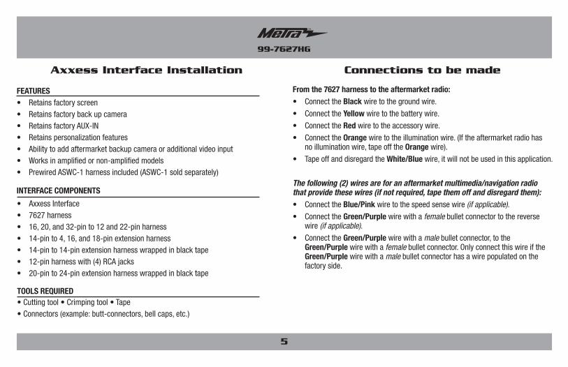
• Retains factory screen• Retains factory back up camera• Retains factory AUX-IN• Retains personalization features• Ability to add aftermarket backup camera or additional video input• Works in amplified or non-amplified models• Prewired ASWC-1 harness included (ASWC-1 sold separately)
FEATURES
• Cutting tool • Crimping tool • Tape • Connectors (example: butt-connectors, bell caps, etc.)
TOOLS REQUIRED
• Axxess Interface• 7627 harness• 16, 20, and 32-pin to 12 and 22-pin harness• 14-pin to 4, 16, and 18-pin extension harness• 14-pin to 14-pin extension harness wrapped in black tape• 12-pin harness with (4) RCA jacks• 20-pin to 24-pin extension harness wrapped in black tape
INTERFACE COMPONENTS
Connections to be made
From the 7627 harness to the aftermarket radio:• Connect the Black wire to the ground wire.
• Connect the Yellow wire to the battery wire.
• Connect the Red wire to the accessory wire.
• Connect the Orange wire to the illumination wire. (If the aftermarket radio has no illumination wire, tape off the Orange wire).
• Tape off and disregard the White/Blue wire, it will not be used in this application.
The following (2) wires are for an aftermarket multimedia/navigation radio that provide these wires (if not required, tape them off and disregard them):• Connect the Blue/Pink wire to the speed sense wire (if applicable).
• Connect the Green/Purple wire with a female bullet connector to the reverse wire (if applicable).
• Connect the Green/Purple wire with a male bullet connector, to the Green/Purple wire with a female bullet connector. Only connect this wire if the Green/Purple wire with a male bullet connector has a wire populated on the factory side.
99-7627HG
Connections to be made
6
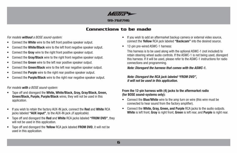
• If you wish to add an aftermarket backup camera or external video source, connect the Yellow RCA jack labeled “Backcam” into the desired source.
• 12-pin pre-wired ASWC-1 harness:
This harness is to be used along with the optional ASWC-1 (not included) to retain steering wheel audio controls. If the ASWC-1 is not being used, disregard this harness. If it will be used, please refer to the ASWC-1 instructions for radio connections and programming.
Note: Disregard the harness that comes with the ASWC-1.
Note: Disregard the RCA jack labeled “FROM DVD”, it will not be used in this application.
From the 12-pin harness with (4) jacks to the aftermarket radio (for BOSE sound-systems only):• Connect the Blue/White wire to the amp turn on wire (this wire must be
connected to hear sound from the factory amplifier).
• Connect the White, Gray, Green, and Purple RCA jacks to the audio outputs. White is left front, Gray is right front, Green is left rear, and Purple is right rear.
For models without a BOSE sound-system:
• Connect the White wire to the left front positive speaker output.
• Connect the White/Black wire to the left front negative speaker output.
• Connect the Gray wire to the right front positive speaker output.
• Connect the Gray/Black wire to the right front negative speaker output.
• Connect the Green wire to the left rear positive speaker output.
• Connect the Green/Black wire to the left rear negative speaker output.
• Connect the Purple wire to the right rear positive speaker output.
• Connect the Purple/Black wire to the right rear negative speaker output.
For models with a BOSE sound-system:
• Tape off and disregard the White, White/Black, Gray, Gray/Black, Green, Green/Black, Purple, Purple/Black wires, they will not be used in this application.
• If you wish to retain the factory AUX-IN jack, connect the Red and White RCA jacks labeled “AUX input”, to the AUX-IN jack (if applicable).
• Tape off and disregard the Red and White RCA jacks labeled “FROM DVD”, they will not be used in this application.
• Tape off and disregard the Yellow RCA jack labeled FROM DVD, it will not be used in this application.
99-7627HG
7
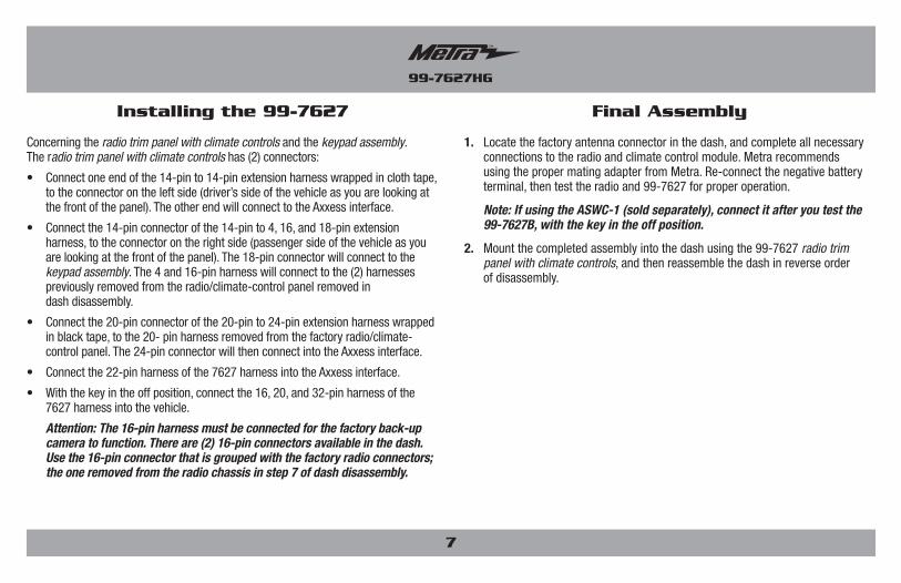
Installing the 99-7627 Final Assembly
Concerning the radio trim panel with climate controls and the keypad assembly. The radio trim panel with climate controls has (2) connectors:
• Connect one end of the 14-pin to 14-pin extension harness wrapped in cloth tape, to the connector on the left side (driver’s side of the vehicle as you are looking at the front of the panel). The other end will connect to the Axxess interface.
• Connect the 14-pin connector of the 14-pin to 4, 16, and 18-pin extension harness, to the connector on the right side (passenger side of the vehicle as you are looking at the front of the panel). The 18-pin connector will connect to the keypad assembly. The 4 and 16-pin harness will connect to the (2) harnesses previously removed from the radio/climate-control panel removed in dash disassembly.
• Connect the 20-pin connector of the 20-pin to 24-pin extension harness wrapped in black tape, to the 20- pin harness removed from the factory radio/climate-control panel. The 24-pin connector will then connect into the Axxess interface.
• Connect the 22-pin harness of the 7627 harness into the Axxess interface.
• With the key in the off position, connect the 16, 20, and 32-pin harness of the 7627 harness into the vehicle.
Attention: The 16-pin harness must be connected for the factory back-up camera to function. There are (2) 16-pin connectors available in the dash. Use the 16-pin connector that is grouped with the factory radio connectors; the one removed from the radio chassis in step 7 of dash disassembly.
1. Locate the factory antenna connector in the dash, and complete all necessary connections to the radio and climate control module. Metra recommends using the proper mating adapter from Metra. Re-connect the negative battery terminal, then test the radio and 99-7627 for proper operation.
Note: If using the ASWC-1 (sold separately), connect it after you test the 99-7627B, with the key in the off position.
2. Mount the completed assembly into the dash using the 99-7627 radio trim panel with climate controls, and then reassemble the dash in reverse order of disassembly.
99-7627HG
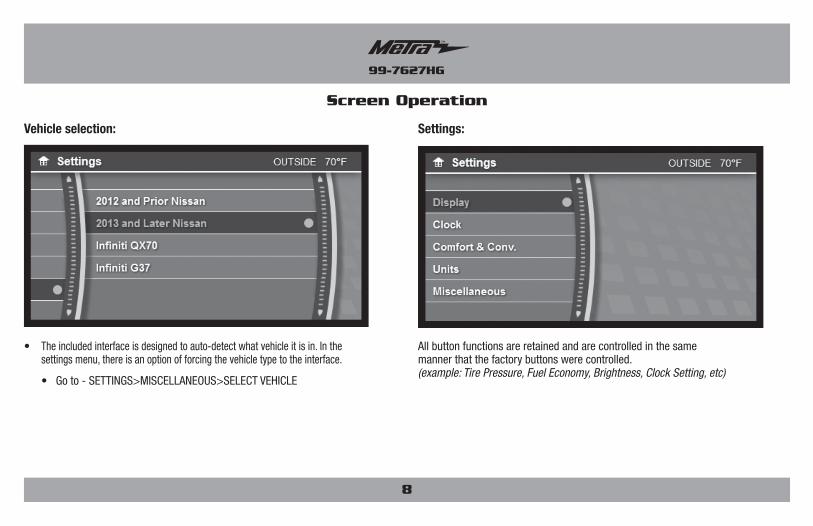
• The included interface is designed to auto-detect what vehicle it is in. In the settings menu, there is an option of forcing the vehicle type to the interface.
• Go to - SETTINGS>MISCELLANEOUS>SELECT VEHICLE
Vehicle selection:
Screen Operation
8
All button functions are retained and are controlled in the same manner that the factory buttons were controlled. (example: Tire Pressure, Fuel Economy, Brightness, Clock Setting, etc)
Settings:
99-7627HG
Screen Operation
9
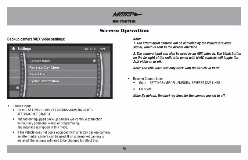
Note: 1. The aftermarket camera will be activated by the vehicle’s reverse
signal, which is sent to the Axxess interface.
2. The camera input can also be used as an AUX video in. The blank button on the far right of the radio trim panel with HVAC controls will toggle the AUX video on or off.
Note: The AUX video will only work with the vehicle in PARK.
• Reverse Camera Lines • Go to – SETTINGS>MISCELLANEOUS> REVERSE CAM LINES
• On or off
Note: By default, the back-up lines for the camera are set to off.
Backup camera/AUX video settings:
• Camera Input • Go to – SETTINGS> MISCELLANEOUS>CAMERA INPUT>
AFTERMARKET CAMERA • The factory equipped back-up camera will continue to function
without any additional wiring or programming. The interface is shipped in this mode.
• If the vehicle does not come equipped with a factory backup camera, an aftermarket camera can be used. If an aftermarket camera is installed, the settings will need to be changed to reflect this.
99-7627HG
10
Screen Operation Updating the 99-7627
• Download and install the WebXXpress software update from axxessinterfaces.com.
• Connect the USB-MINI-CAB update cable (sold separately) between the 99-7627 and the computer. The cable will connect into the port on the rear of the kit labeled “A”.
Note: The 99-7627 will need to be powered up to be updated.
• From the Start Menu of the computer, click on “USB Bootloader”, and then click “Update Board”. The software will begin to download at this point.
Note: If 30 seconds elapses before you finish this step, you will need to remove power from the 99-7627, then reapply power, and then start the update process again.
Note: Please note which firmware downloaded to the interface. This will help in troubleshooting, if need be.
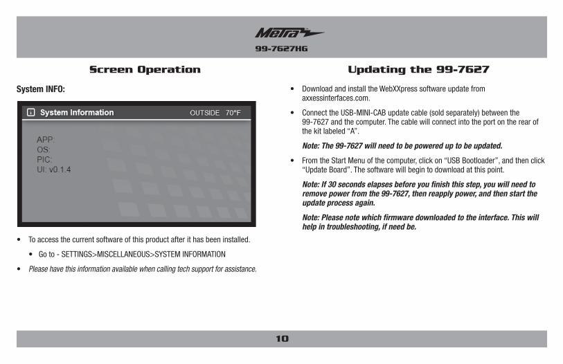
• To access the current software of this product after it has been installed.
• Go to - SETTINGS>MISCELLANEOUS>SYSTEM INFORMATION
• Please have this information available when calling tech support for assistance.
System INFO:
99-7627HG
11
REV.
12/
14/2
017
INS
T99-
7627
HG
KNOWLEDGE IS POWEREnhance your installation and fabrication skills by enrolling in the most recognized and respected mobile electronics school in our industry.Log onto www.installerinstitute.com or call 800-354-6782 for more information and take steps toward a better tomorrow.
Metra recommends MECP certified technicians
Installation instructions for part 99-7627HG
METRA. The World’s best kits.® metraonline.com © COPYRIGHT 2017 METRA ELECTRONICS CORPORATION
IMPORTANTIf you are having difficulties with the installation of this product, please call our Tech Support line at 1-800-253-TECH. Before doing so, look over the instructions a second time, and make sure the installation was performed exactly as the instructions are stated. Please have the vehicle apart and ready to perform troubleshooting steps before calling.
INSTRUCCIONES DE INSTALACIÓN PARA LA PIEZA 99-7627HG
REV.
12/
14/2
017
INS
T99-
7627
HG
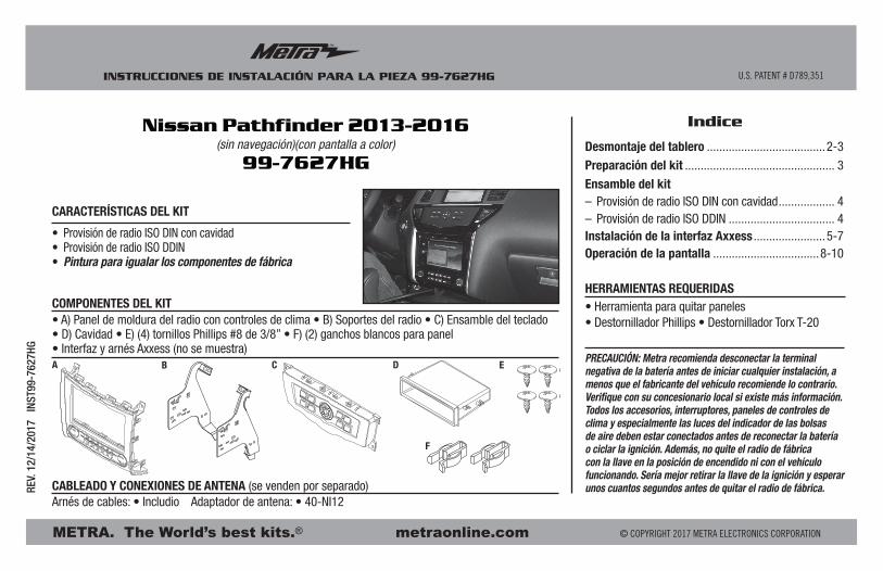
PRECAUCIÓN: Metra recomienda desconectar la terminal negativa de la batería antes de iniciar cualquier instalación, a menos que el fabricante del vehículo recomiende lo contrario. Verifique con su concesionario local si existe más información. Todos los accesorios, interruptores, paneles de controles de clima y especialmente las luces del indicador de las bolsas de aire deben estar conectados antes de reconectar la batería o ciclar la ignición. Además, no quite el radio de fábrica con la llave en la posición de encendido ni con el vehículo funcionando. Sería mejor retirar la llave de la ignición y esperar unos cuantos segundos antes de quitar el radio de fábrica.
Indice
U.S. PATENT # D789,351
METRA. The World’s best kits.® metraonline.com © COPYRIGHT 2017 METRA ELECTRONICS CORPORATION
• Herramienta para quitar paneles • Destornillador Phillips • Destornillador Torx T-20
HERRAMIENTAS REQUERIDAS
• Provisión de radio ISO DIN con cavidad• Provisión de radio ISO DDIN• Pintura para igualar los componentes de fábrica
• A) Panel de moldura del radio con controles de clima • B) Soportes del radio • C) Ensamble del teclado • D) Cavidad • E) (4) tornillos Phillips #8 de 3/8” • F) (2) ganchos blancos para panel • Interfaz y arnés Axxess (no se muestra)
CARACTERÍSTICAS DEL KIT
COMPONENTES DEL KIT
CABLEADO Y CONEXIONES DE ANTENA (se venden por separado) Arnés de cables: • Includio Adaptador de antena: • 40-NI12
Nissan Pathfinder 2013-2016(sin navegación)(con pantalla a color)
99-7627HG
A DC E
F
B
Desmontaje del tablero ......................................2-3
Preparación del kit ................................................ 3
Ensamble del kit– Provisión de radio ISO DIN con cavidad .................. 4– Provisión de radio ISO DDIN .................................. 4Instalación de la interfaz Axxess .......................5-7Operación de la pantalla ..................................8-10
99-7627HG
Desmontaje del tablero
2
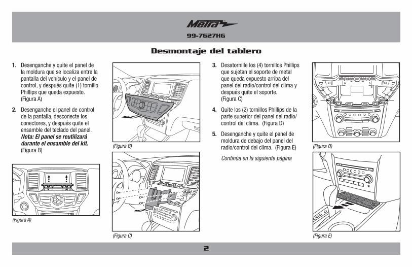
1. Desenganche y quite el panel de la moldura que se localiza entre la pantalla del vehículo y el panel de control, y después quite (1) tornillo Phillips que queda expuesto. (Figura A)
2. Desenganche el panel de control de la pantalla, desconecte los conectores, y después quite el ensamble del teclado del panel. Nota: El panel se reutilizará durante el ensamble del kit. (Figura B)
3. Desatornille los (4) tornillos Phillips que sujetan el soporte de metal que queda expuesto arriba del panel del radio/control del clima y después quite el soporte. (Figura C)
4. Quite los (2) tornillos Phillips de la parte superior del panel del radio/ control del clima. (Figura D)
5. Desenganche y quite el panel de moldura de debajo del panel del radio/control del clima. (Figura E)
Continúa en la siguiente página
(Figura A)
(Figura E)
(Figura D)(Figura B)
(Figura C)
99-7627HG
3
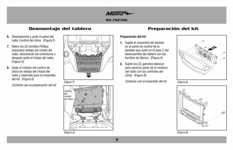
6. Desenganche y quite el panel del radio /control del clima. (Figura F)
7. Retire los (2) tornillos Phillips expuestos debajo del chasis del radio, desconecte los conectores y después quite el chasis del radio. (Figura G)
8. Quite el módulo del control de clima de debajo del chasis del radio y resérvelo para el ensamble del kit. (Figura G)
Continúe con la preparación del kit
Desmontaje del tablero Preparación del kit
(Figura F)
(Figura G)
módulo del control de clima
Preparación del kit
1. Sujete el ensamble del teclado en el panel de control de la pantalla que quitó en el paso 2 del desensamble del tablero con los tornillos de fábrica. (Figura A)
2. Sujete los (2) ganchos blancos para panel al panel de la moldura del radio con los controles del clima. (Figura B)
Continúe con el ensamble del kit (Figura A)
(Figura B)
99-7627HG
Ensamble del kit
4
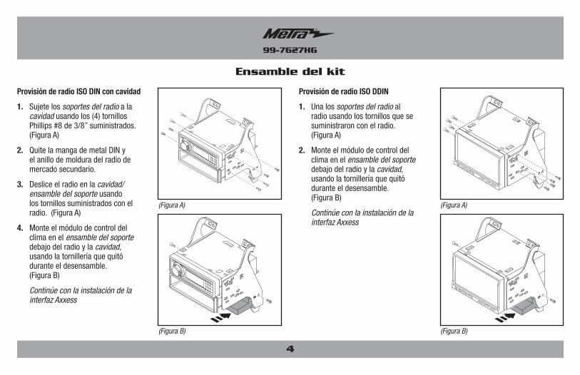
Provisión de radio ISO DIN con cavidad
1. Sujete los soportes del radio a la cavidad usando los (4) tornillos Phillips #8 de 3/8” suministrados. (Figura A)
2. Quite la manga de metal DIN y el anillo de moldura del radio de mercado secundario.
3. Deslice el radio en la cavidad/ensamble del soporte usando los tornillos suministrados con el radio. (Figura A)
4. Monte el módulo de control del clima en el ensamble del soporte debajo del radio y la cavidad, usando la tornillería que quitó durante el desensamble. (Figura B)
Continúe con la instalación de la interfaz Axxess
Provisión de radio ISO DDIN
1. Una los soportes del radio al radio usando los tornillos que se suministraron con el radio. (Figura A)
2. Monte el módulo de control del clima en el ensamble del soporte debajo del radio y la cavidad, usando la tornillería que quitó durante el desensamble. (Figura B)
Continúe con la instalación de la interfaz Axxess
(Figura A)
(Figura B)
(Figura A)
(Figura B)
99-7627HG
5
Instalación de la interfaz Axxess Conexiones que se deben hacer
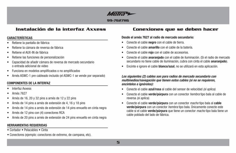
• Retiene la pantalla de fábrica• Retiene la cámara de reversa de fábrica• Retiene el AUX-IN de fábrica• Retiene las funciones de personalización• Capacidad de añadir cámara de reversa de mercado secundario
o entrada adicional de video• Funciona en modelos amplificados o no amplificados• Arnés ASWC-1 pre cableado incluido (el ASWC-1 se vende por separado)
CARACTERÍSTICAS
• Cortador • Pelacables • Cinta• Conectores (ejemplo: conectores de extremo, de campana, etc).
HERRAMIENTAS REQUERIDAS
• Interfaz Axxess• Arnés 7627• Arnés de 16, 20 y 32 pins a arnés de 12 y 22 pins• Arnés de 14 pins a arnés de extensión de 4, 16 y 18 pins• Arnés de 14 pins a arnés de extensión de 14 pins envuelto en cinta negra• Arnés de 12 pins con (4) conectores RCA• Arnés de 20 pins a arnés de extensión de 24 pins envuelto en cinta negra
COMPONENTES DE LA INTERFAZ
Desde el arnés 7627 al radio de mercado secundario:• Conecte el cable negro con el cable de tierra.
• Conecte el cable amarillo con el cable de la batería.
• Conecte el cable rojo con el cable de accesorios.
• Conecte el cable anaranjado con el cable de iluminación. (Si el radio de mercado secundario no tiene cable de iluminación, cubra con cinta el cable anaranjado).
• Encinte e ignore el cable blanco/azul, no se utilizará en esta aplicación.
Los siguientes (2) cables son para radios de mercado secundario con multimedios/navegación que tienen estos cables (si no se requieren, encíntelos e ignórelos):• Conecte el cable azul/rosa al cable del sensor de velocidad (si aplica).
• Conecte el cable verde/púrpura con un conector hembra tipo bala al cable de reversa (si aplica).
• Conecte el cable verde/púrpura con un conector macho tipo bala al cable verde/púrpura con un conector hembra tipo bala. Únicamente conecte este cable si el cable verde/púrpura que tiene un conector macho tipo bala tiene un cable poblado del lado de fábrica.
99-7627HG
6
Conexiones que se deben hacer
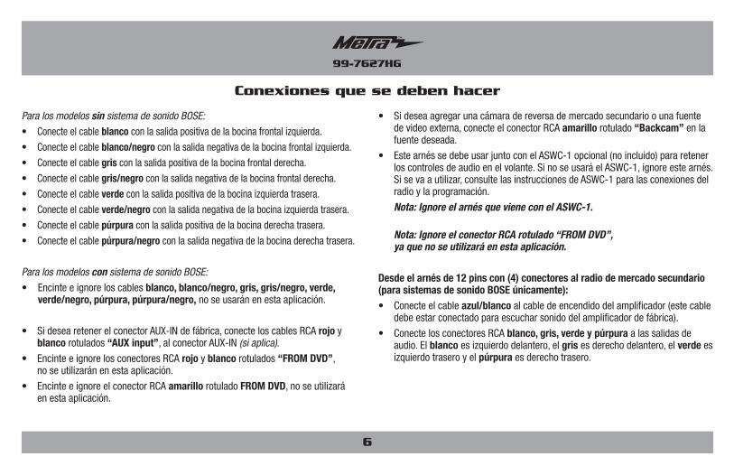
• Si desea agregar una cámara de reversa de mercado secundario o una fuente de video externa, conecte el conector RCA amarillo rotulado “Backcam” en la fuente deseada.
• Este arnés se debe usar junto con el ASWC-1 opcional (no incluido) para retener los controles de audio en el volante. Si no se usará el ASWC-1, ignore este arnés. Si se va a utilizar, consulte las instrucciones de ASWC-1 para las conexiones del radio y la programación.
Nota: Ignore el arnés que viene con el ASWC-1.
Nota: Ignore el conector RCA rotulado “FROM DVD”, ya que no se utilizará en esta aplicación.
Desde el arnés de 12 pins con (4) conectores al radio de mercado secundario (para sistemas de sonido BOSE únicamente):• Conecte el cable azul/blanco al cable de encendido del amplificador (este cable
debe estar conectado para escuchar sonido del amplificador de fábrica).
• Conecte los conectores RCA blanco, gris, verde y púrpura a las salidas de audio. El blanco es izquierdo delantero, el gris es derecho delantero, el verde es izquierdo trasero y el púrpura es derecho trasero.
Para los modelos sin sistema de sonido BOSE:
• Conecte el cable blanco con la salida positiva de la bocina frontal izquierda.
• Conecte el cable blanco/negro con la salida negativa de la bocina frontal izquierda.
• Conecte el cable gris con la salida positiva de la bocina frontal derecha.
• Conecte el cable gris/negro con la salida negativa de la bocina frontal derecha.
• Conecte el cable verde con la salida positiva de la bocina izquierda trasera.
• Conecte el cable verde/negro con la salida negativa de la bocina izquierda trasera.
• Conecte el cable púrpura con la salida positiva de la bocina derecha trasera.
• Conecte el cable púrpura/negro con la salida negativa de la bocina derecha trasera.
Para los modelos con sistema de sonido BOSE:
• Encinte e ignore los cables blanco, blanco/negro, gris, gris/negro, verde, verde/negro, púrpura, púrpura/negro, no se usarán en esta aplicación.
• Si desea retener el conector AUX-IN de fábrica, conecte los cables RCA rojo y blanco rotulados “AUX input”, al conector AUX-IN (si aplica).
• Encinte e ignore los conectores RCA rojo y blanco rotulados “FROM DVD”, no se utilizarán en esta aplicación.
• Encinte e ignore el conector RCA amarillo rotulado FROM DVD, no se utilizará en esta aplicación.
99-7627HG
7
Instalación del 99-7627 Ensamble final
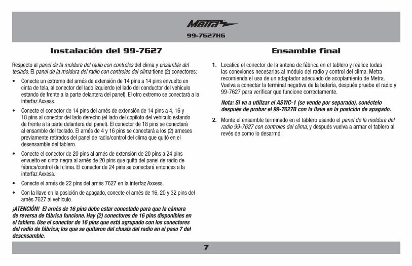
Respecto al panel de la moldura del radio con controles del clima y ensamble del teclado. El panel de la moldura del radio con controles del clima tiene (2) conectores:
• Conecte un extremo del arnés de extensión de 14 pins a 14 pins envuelto en cinta de tela, al conector del lado izquierdo (el lado del conductor del vehículo estando de frente a la parte delantera del panel). El otro extremo se conectará a la interfaz Axxess.
• Conecte el conector de 14 pins del arnés de extensión de 14 pins a 4, 16 y 18 pins al conector del lado derecho (el lado del copiloto del vehículo estando de frente a la parte delantera del panel). El conector de 18 pins se conectará al ensamble del teclado. El arnés de 4 y 16 pins se conectará a los (2) arneses previamente retirados del panel de radio/control del clima que quitó en el desensamble del tablero.
• Conecte el conector de 20 pins al arnés de extensión de 20 pins a 24 pins envuelto en cinta negra al arnés de 20 pins que quitó del panel de radio de fábrica/control del clima. El conector de 24 pins se conectará entonces a la interfaz Axxess.
• Conecte el arnés de 22 pins del arnés 7627 en la interfaz Axxess.
• Con la llave en la posición de apagado, conecte el arnés de 16, 20 y 32 pins del arnés 7627 al vehículo.
¡ATENCIÓN! El arnés de 16 pins debe estar conectado para que la cámara de reversa de fábrica funcione. Hay (2) conectores de 16 pins disponibles en el tablero. Use el conector de 16 pins que está agrupado con los conectores del radio de fábrica; los que se quitaron del chasis del radio en el paso 7 del desensamble.
1. Localice el conector de la antena de fábrica en el tablero y realice todas las conexiones necesarias al módulo del radio y control del clima. Metra recomienda el uso de un adaptador adecuado de acoplamiento de Metra. Vuelva a conectar la terminal negativa de la batería, después pruebe el radio y 99-7627 para verificar que funcione correctamente.
Nota: Si va a utilizar el ASWC-1 (se vende por separado), conéctelo después de probar el 99-7627B con la llave en la posición de apagado.
2. Monte el ensamble terminado en el tablero usando el panel de la moldura del radio 99-7627 con controles del clima, y después vuelva a armar el tablero al revés de como lo desarmó.
99-7627HG
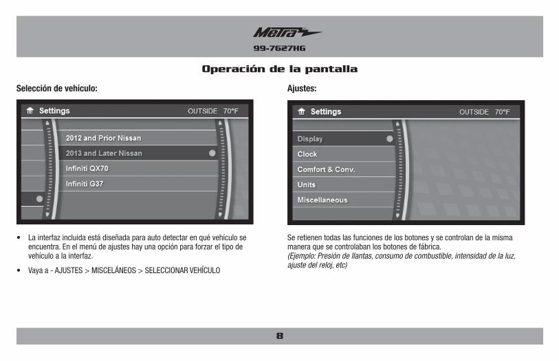
• La interfaz incluida está diseñada para auto detectar en qué vehículo se encuentra. En el menú de ajustes hay una opción para forzar el tipo de vehículo a la interfaz.
• Vaya a - AJUSTES > MISCELÁNEOS > SELECCIONAR VEHÍCULO
Selección de vehículo:
Operación de la pantalla
8
Se retienen todas las funciones de los botones y se controlan de la misma manera que se controlaban los botones de fábrica. (Ejemplo: Presión de llantas, consumo de combustible, intensidad de la luz, ajuste del reloj, etc)
Ajustes:
99-7627HG
Operación de la pantalla
9
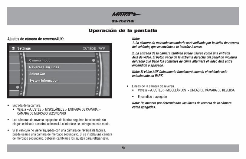
Nota: 1. La cámara de mercado secundario será activada por la señal de reversa
del vehículo, que es enviada a la interfaz Axxess.
2. La entrada de la cámara también puede usarse como una entrada AUX de video. El botón vacío de la extrema derecha del panel de moldura del radio que tiene los controles de clima alternará el video AUX entre encendido o apagado.
Nota: El video AUX únicamente funcionará cuando el vehículo esté estacionado en PARK.
• Líneas de la cámara de reversa • Vaya a – AJUSTES > MISCELÁNEOS > LÍNEAS DE CÁMARA DE REVERSA
• Encendido o apagado
Nota: De manera pre determinada, las líneas de reversa de la cámara están apagadas.
Ajustes de cámara de reversa/AUX:
• Entrada de la cámara • Vaya a – AJUSTES > MISCELÁNEOS > ENTRADA DE CÁMARA >
CÁMARA DE MERCADO SECUNDARIO
• Las cámaras de reversa equipadas de fábrica seguirán funcionando sin ningún cableado o control adicional. La interfase se entrega en este modo.
• Si el vehículo no viene equipado con una cámara de reversa de fábrica, puede usarse una cámara de mercado secundario. Si se instala una cámara de mercado secundario, deberán cambiarse los ajustes para reflejar esto.
99-7627HG
10
Operación de la pantalla Actualización del 99-7627
• Descargue e instale la actualización del software WebXXpress en axxessinterfaces.com.
• Conecte el cable de actualización USB-MINI-CAB (se vende por separado) entre el 99-7627 y la computadora. El cable se conectará al puerto de la parte posterior del kit rotulada “A”.
Nota: El 99-7627 no necesitará estar encendido para actualizarse.
• Desde el menú de inicio de la computadora, haga clic en “USB Bootloader” y luego haga clic en “Actualizar tablero”. El software empezará a descargarse en este momento.
Nota: Si pasan 30 segundos antes de que termine este paso, tendrá que desconectar la alimentación al 99-7627, luego reaplicar la alimentación e iniciar de nuevo el proceso de actualización.
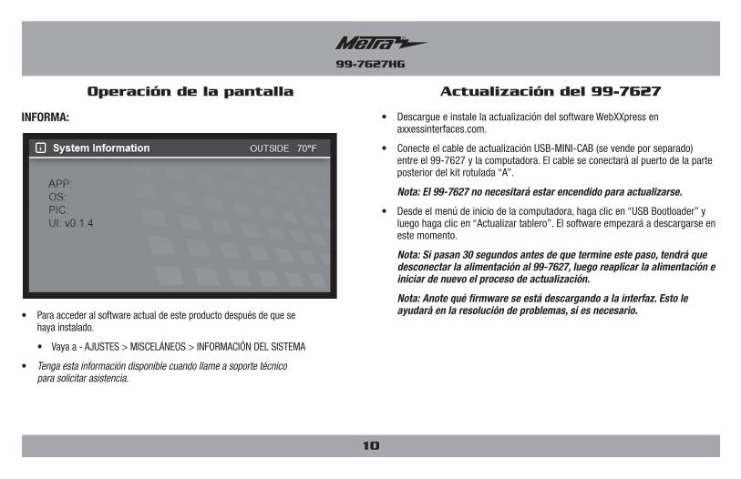
Nota: Anote qué firmware se está descargando a la interfaz. Esto le ayudará en la resolución de problemas, si es necesario.• Para acceder al software actual de este producto después de que se
haya instalado.
• Vaya a - AJUSTES > MISCELÁNEOS > INFORMACIÓN DEL SISTEMA
• Tenga esta información disponible cuando llame a soporte técnico para solicitar asistencia.
INFORMA:
99-7627HG
11
INSTRUCCIONES DE INSTALACIÓN PARA LA PIEZA 99-7627HG
REV.
12/
14/2
017
INS
T99-
7627
HG
KNOWLEDGE IS POWEREnhance your installation and fabrication skills by enrolling in the most recognized and respected mobile electronics school in our industry.Log onto www.installerinstitute.com or call 800-354-6782 for more information and take steps toward a better tomorrow.
Metra recomienda técnicos con certificación del Programa de Certificación en Electrónica Móvil (Mobile Electronics Certification Program, MECP).
EL CONOCIMIENTO ES PODERMejore sus habilidades de instalación y fabricación inscribiéndose en la escuela de dispositivos electrónicos móviles más reconocida y respetada de nuestra industria. Regístrese en www.installerinstitute.com o llame al 800-354-6782 para obtener más información y avance hacia un futuro mejor.
IMPORTANTESi tiene dificultades con la instalación de este producto, llame a nuestra línea de soporte técnico al 1-800-253-TECH. Antes de hacerlo, revise las instrucciones por segunda vez y asegúrese de que la instalación se haya realizado exactamente como se indica en las instrucciones. Por favor tenga el vehículo desarmado y listo para ejecutar los pasos de resolución de problemas antes de llamar.
METRA. The World’s best kits.® metraonline.com © COPYRIGHT 2017 METRA ELECTRONICS CORPORATION