wm1 serieswm1 series - toolimpex.com · wm1 serieswm1 series workshop microscope high tech – low...
TRANSCRIPT

WM1 SeriesWM1 Series
Workshop Microscope
High Tech – Low Budget, with integrated image analysisideal for measuring
punched parts
plastic parts
rubber parts
tools
seal
profiles
and many more parts
SIMPLY PRECISE

WM1 Series
Three tailor-made solutionsto your measuring task.
For more detailed information, please visit ourWebsite: www.dr-schneider.de
A wide range of accessories are available.
WM1 250 / WM1 300
• Multicount 3000• High-resolution CCD camera• 1.5x magnification• Incident light illumination through LED ring light,• 4 sectors and 1 ring – separately switchable• Needle-bearing supported precision measuring stage with quick-adjustment feature
for axes X and Y• Diode laser indicating camera position
Your benefits at a glance
• Camera-based acquisition of measurement data• Precise edge detection in transmitted and incident light
thanks to intelligent image analysis algorithms• Small size – great performance• Fast and easy handling combined with impressive
measurement precision
Regardless of whether you opt for the manual model equippedwith either Multicount 3000, which features an integrated imageanalysis module, or with SAPHIR, an accurate measuring andanalysis software – or whether you choose the CNC-operatedmodel, which can be optionally expanded into a ‘small’ multi-sensor device: the WM1 series ensures tailor-made solutions designed to match your needs and budget, 100% and no less.

WM1 250 S / WM1 300 S
• Measuring and analysis software SAPHIR• CCD camera with ultra-high resolution• 1.5x magnification• Incident light illumination through LED ring light• 4 sectors and 1 ring – separately switchable• Needle-bearing supported precision measuring stage with quick-adjustment feature
for axes X and Y• Diode laser indicating camera position• Colour inkjet printer• 19” TFT flat screen monitor
WM1 250 CNC / WM1 300 CNC / WM1 400 CNC
• Measuring and analysis software SAPHIR• 3-axis CNC control • CCD camera with ultra-high resolution• 1.5x magnification• Incident light illumination through LED ring light,
4 sectors and 1 ring – separately switchable• Needle-bearing supported precision measuring stage
for axes X and Y• Diode laser indicating of camera position• Colour inkjet printer• Joystick for axis motion control, with fast/slow speed selection• 19” TFT flat screen monitor• Optional: touch-trigger probe TP200
A valuable option:
Touch-trigger probe
TP200

Type Multicount 3000
SAPHIR manual model
SAPHIR CNC model
Measuring range X x Y mm
Z mm
Objective
Magnification
Image field mm
Working distance mm
Resolution mm
Max. workpiece weight
on glass plate kg
Length measurement uncertainty1 1)
DIN EN ISO 10360-2
VDI/VDE 2617
Our measurement is based on
Dimensions mm
Weight kg
Electric power supply
WM1 250 WM1 300 –
WM1 250 S WM1 300 S –
WM1 250 CNC WM1 300 CNC WM1 400 CNC
250 x 125 300 x 200 400 x 300
200 200 200
other objectives available upon request
1.5 x 3 x
4.3 x 3.2 2.1 x 1.6
77 77
0.0001
20
E1 = (1.9+L/100 mm)µm
E2 = (2.9+L/100 mm)µm
E1Z = (3.9+L/100 mm)µm
measuring length L in mm
� 2) = 1.5 -̂ objective 1.5 x (image field 4 x 3 mm) – smaller image fields (3 x,5 x,10 x) enable greater accuracy
W 520 W 900 W 1200
D 650 D 950 D 1200
H 750 H 950 H 1000
110 140 500
220-240VAC, 50-60Hz, 1kW
1) Prerequisites: Admissible ambient conditions 20 °C ± 1K, Temperature gradient �th = 0.5 K/h, �td = 4.0 K/d2) � = Magnification factor
Technical Specifications of the WM1 Series
Dr. Heinrich Schneider Messtechnik GmbH · Rotlay-Mühle · 55545 Bad Kreuznach · GermanyTel. +49 (0) 671 291 02 · Fax +49 (0) 671 291 200 · [email protected] · www.dr-schneider.de Te
chni
cal m
odifi
catio
ns r
eser
ved
– 04
.200
9/W
D/R
DL
SAPHIR measuring and analysis softwareThe foundations for efficient and cost-conscious work are already laid at theearly stage of programme development. Since “Schneider” is the Germanword for “tailor”, you can rightly conclude that SAPHIR is a truly “tailor-made”measuring software that will leave nothing to be desired: from “A” as in “axisalignment” to “Z” as in “zero-point administration” - SAPHIR offers a wealthof useful features. Further details are provided in our “SAPHIR” brochure,which we will be pleased to send to you, free of charge, upon request.
Geometry measurement computer Multicount 3000 - brings data to lifeFor the first time ever, MC 3000 combines recorded position data with the live imageof the object being measured in one device. Whereas formerly either digital display ele-ments or readouts such as Multicount 200/2000 were used on measuring projectors,the new Multicount 3000 device is a real “all-rounder”, offering all the advantages ofMulticount 200/2000 with the added benefits of image analysis, live imaging and auto-matic edge detection. Further details can be gleaned from our “MULTICOUNT” bro-chure, which we will be pleased to send to you, free of charge, upon request.

WMM 100/200WMM 100/200
Shaft Measuring Machines WMM 100/200
As easy as it gets.
Diameters
Lengths
Radii
Chamfers
Threads
Fast as a flash, safe,
accurate, precise
SIMPLY PRECISE

WMM 100 WMM 200
100 200
60 60
0.3x
100x60
3
E2 = (2,0+L/100 mm)µm measuring length L in mm
� = 0,3 -̂ objective 0.3x (image field 100 x 60mm) – the measurement uncertainty value is valid for the indicated image field
W=1000 D=750 H=800 W=1000 D=750 H=900
100 120
220-240VAC, 50-60Hz, 1kW
Model
Measuring range mm
Length
Diameter
Objective
Magnification mm
Image field mm
Workpiece weight max. kg
Length measurement uncertainty 1)
DIN EN ISO 10360-2, VDI/VDE 2617
Our measurement is based on
Machine dimensions 2) mm
Weight kg
Power supply
1) Ambient conditions 20 °C ± 1K, Temperature gradient �th = 1K/h, �td = 4.0 K/d,
measured with a calibrated standard, working conditions: 15…35 °C. 2) Height incl. touch screen
Technical Specifications of WMM 100/200
Tech
nica
l mod
ifica
tions
res
erve
d –
04.2
010/
AV
/RD
L
Dr. Heinrich Schneider Messtechnik GmbH · Rotlay-Mühle · 55545 Bad Kreuznach · GermanyTel. +49 (0) 671 291 02 · Fax +49 (0) 671 291 200 · [email protected] · www.dr-schneider.de
Benefits of WMM 100/200
• Easy and fast measurement providing results within seconds
• Intuitive user interface• No instruction required• Portable design• Accurate and precise measurement
Standard features of WMM 100/200
• Image field 100*60 mm• 16-megapixel camera• Touch-screen PC• Table-top design
Optional features of WMM 100/200
• Rotary axis• 200 mm measuring length
WMM100/200As easy as it gets.Fields of application of WMM 100/200
The newest member in the family of shaftmeasuring machines has all it takes to bea star. Its large image field of 100*60mmensures accurate, precise and reliablemeasuring results. Quality counts in ourworld, and so does time. We therefore donot need to go back to ancient wisdomto discover that time is the most valuablething we can spend – and save. Since theWMM machine is equipped with apowerful 16-megapixel CCD camera,quality measurement becomes a matterof seconds. What easier way could therebe to save time without compromisingquality! Thanks to the intuitive user inter-face, which is backed by the proven mea-surement and analysis software SAPHIR,even newcomers to the world of metrolo-gy can rest assured that their quickly andeasily obtained measurement results willleave nothing to be desired in terms ofreliability.
WMM – As easy as it gets.
For further information, please visit our website: www.dr-schneider.de

VideoCAD SeriesVideoCAD Series
2D Optical Measuring Device
For fast and accurate measurementof two-dimensional geometries
SIMPLY PRECISE

VideoCAD Series
2D optical area measurement device – for objects of up to 230 mm in size.
Fields of operation
The products of the VideoCAD series developedby Dr. Heinrich Schneider Messtechnik ensureprecise and fast measurement of two-dimensio-nal geometries. They come in three sizes(VideoCAD 1, 2 and 3) and are ideally suited formeasuring profiles made of plastic, aluminium,wood, rubber, rubber-metal and metal, as well asfor measuring stamped / punched parts of anykind, templates, seals, layouts and many moreobjects – also in serial production.
The high-resolution optics of all VideoCAD mea-suring devices ensure distortion-free measure-ment with excellent depth of field over the enti-re calibrated measuring range. In this way, evenworkpieces of up to 60 mm in height can bemeasured in different planes.
Outstanding features
• Unsurpassed measuring speed: The acquisition and analysis of measured data only takes a few milliseconds
• Two-dimensional geometries are captured in one image
• Monochrome ultra-high definition camera ensures resolutions in the µm range
For more detailed information, please visit our Website at: www.dr-schneider.de
VideoCAD 1 is a portable video measuring device for acqui-sition of data relating to two-dimensional objects of up to60 x 80 mm in size.
Special features of the VideoCAD series
• Ultra-high resolution camera with high-precision telecentric objectives• Distortion-free calibrated measuring range• Both the level of geometrical resolution and the measuring range depend on the camera/objective
combination used (cf. table for details).
Further assets of the VideoCAD series
• 2D digitisation and BestFit function included in the basic scope of supply• Axis movement is not required, which enables data acquisition within fractions of a second• Mobile integration into the manufacturing process is an option
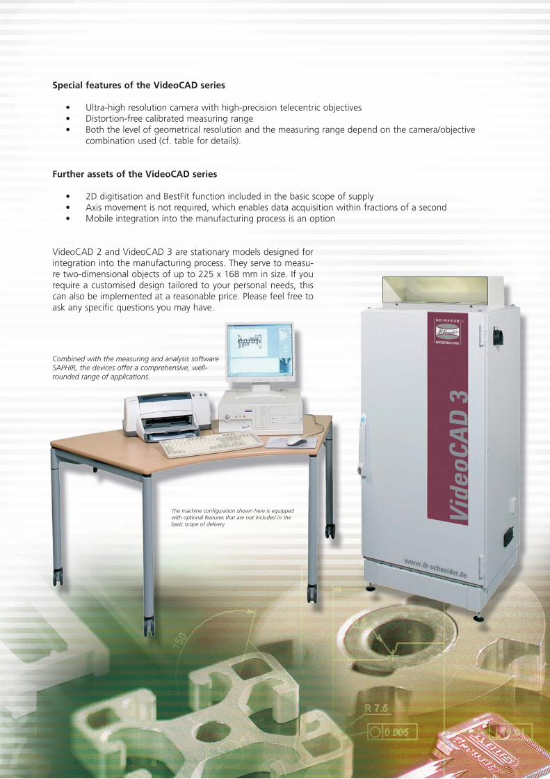
VideoCAD 2 and VideoCAD 3 are stationary models designed forintegration into the manufacturing process. They serve to measu-re two-dimensional objects of up to 225 x 168 mm in size. If yourequire a customised design tailored to your personal needs, thiscan also be implemented at a reasonable price. Please feel free toask any specific questions you may have.
Combined with the measuring and analysis softwareSAPHIR, the devices offer a comprehensive, well-rounded range of applications.
The machine configuration shown here is equippedwith optional features that are not included in thebasic scope of delivery

Type
Measuring range mm
Object height max. mm
Objective
Magnification
Camera
Max. workpiece weight
on glass plate kg
Length measurement uncertainty 1)
DIN EN ISO 10360-2
VDI/VDE 2617
Dimensions mm
PC workstation not included
Weight kg
Electrical power supply
VideoCAD 1 VideoCAD 2 VideoCAD 3
X 80 X 144 X 225
Y 60 Y 108 Y 168
other measuring ranges upon request
60
Telecentric special objective
0.1x 0.06x 0.036x
5 mega pixel b/w CCD matrix camera
20
E2 = (4.0+L/50 mm)µm E2 = (6.0+L/50 mm)µm E2 = (10.0+L/50 mm)µm
Measuring length L in mm
W 290 W 650 W 650
D 720 D 680 D 680
H 550 H 1800 H 1800
50 150 150
220-240VAC, 50-60Hz, 1kW
1) Prerequisites: Admissible ambient conditions 20 °C ± 1K, Temperature gradient �th = 0.5 K/h, �td = 4.0 K/d
Technical Specifications of the VideoCAD Series
Dr. Heinrich Schneider Messtechnik GmbH · Rotlay-Mühle · 55545 Bad Kreuznach · GermanyTel. +49 (0) 671 291 02 · Fax +49 (0) 671 291 200 · [email protected] · www.dr-schneider.de Te
chni
cal m
odifi
catio
ns r
eser
ved
– 04
.200
9/W
D/R
DL
SAPHIR measuring and analysis softwareThe foundations for efficient and cost-conscious work are already laid at theearly stage of programme development. Since “Schneider” is the Germanword for “tailor”, you can rightly conclude that SAPHIR is a truly “tailor-made”measuring software that will leave nothing to be desired: from “A” as in “axisalignment” to “Z” as in “zero-point administration” – SAPHIR offers a wealthof useful features. Further details are provided in our “SAPHIR” brochure,which we will be pleased to send to you, free of charge, upon request.

WMM SeriesWMM Series
Shaft Measuring Machines
Precise measurement of lengths, diameters, radii, angles,chamfers, as well as of concentricity and coaxiality – forreduced cycle times on workpieces of up to 1000 mm in length.
SIMPLY PRECISE

WMM Series
Shaft measuring machinefor measuring of objectsup to 1000 mm in length
The machine configurationshown here has optional features that are not includedin the basic scope of delivery.
The machines of the WMM 300 line are designed for measuring shafts of up to 300 mm in length and 80 mm in diameter.
Fields of application of the WMM series
The machines of the WMM series provide anultra-fast solution for the precise measurementof rotationally objects of up to 1000 mm inlength and 400 mm in diameter. Lengths anddiameters, as well as radii, angles, and chamferscan be measured in one single operation.
The WMM programme will help you to reduce your cycle times.
Thanks to its exceptionally high measuringspeed, easy operation, as well as SAPHIR-basedmeasurement and analysis features, this system isparticularly appropriate for use in the workshopand in the measuring room.
It's main advantages over comparable systemsare it's high accuracy and precision not only inthe measurement of diameters, but also oflengths, small contours, radii, as well as of groo-ves in rotationally symmetric measuring objects.Another benefit of the machine is its ability toperform incident-light measurements on botto-med holes/blind holes, grooves as well as onother elements and contours that are not suitablefor measurement in transmitted light.
Highly efficient additional options, such as afully integrated CNC rotation axis and precisemeasurement in sectoral incident illuminati-on, make this system an indispensable, time-and money-saving asset for a wide variety ofmeasuring tasks.
The modular design of the WMM seriesensures customised solutions for almostany application
Do you require longer measuring lengths, a spe-cial clamping device, or do you need a devicewith features that goes beyond the standardconfiguration? No problem for us: All machinesof the WMM series can be equipped with featu-res tailored to your specific needs.
The WMM series is specially designed for measuring shafts up to 1000 mm in length

The premium class of measuringsystems for turned parts and shaftshas been newly defined with thedevelopent of WMM 1000. “Everything from one source” is the principle applied in the design of the WMM series.
Now you can also reduce your cycle times.
Because WMM will help you capture the smallest detail quickly and reliably.
Optional features of the WMM series
• Fully integrated CNC rotation axis SK40, SK50 or HSK63• Incident illumination for the measurement of grooves, oil gallery bores, blind holes, and milling contours• Touch-trigger or scanning probe allowing measurement of special shapes,
such as gear teeth, non-cylindrically symmetric contours, impeller wheels etc.• Digitisation and BestFit• Wide variety of clamping devices, such as dead and live centres, precision jaw chucks, precision collet chucks,
hollow centres, etc.
Standard features of the WMM series
• Measuring range of up to 1000 mm in length, and up to 400 mm in diameter • Ultra-fast measuring technique due to triggered data acquisition by means of a high-resolution
CCD matrix camera• Highly accurate measurement also of lengths by means of a contour focussing element,
even beyond the central axis• Teach-in programming• Automatic generation of measurement reports,
graphical measurement reports, and first-sample test reports in accordance with VDA (Association of the German Automotive Industry)
Special assets of the WMM series
• High measuring accuracy and precision• Easy operation• Outstanding
measuring speed• Excellent data
reporting• Ergonomic design
with optimum accessibility
For further information, please visit our Website: www.dr-schneider.de
A touch-trigger or scanning probe for the measurementof special shapes, such as gear teeth,non-cylindrically symmetric contours,impeller wheels etc., is optionally available.

WMM 300 WMM 600 WMM 1000 WMM 1000/400
300 600 1000 1000
80 200 200 400
telecentric
5.6 x4.1
0.1
3 axes, optionally 4 axes
50 50 50 50
– 200 200 200
E2 = (2.0+L/200 mm)µm Measuring length L in mm
� 3) = 1.0 -̂ objektive1.0x (image field 5.6 x 4.1mm) – with smaller image fields (1.5x,3x,5x) greater accuracy can be achieved!
W 620 W 950 W 950 W 1400
D 640 D 1000 D 1000 D 1370
H 870 H 2200 H 2500 H 2500
– 800 x 800
400 2600 3200 4500
220-240VAC, 50-60Hz, 1kW
Dr. Heinrich Schneider Messtechnik GmbH · Rotlay-Mühle · 55545 Bad Kreuznach · GermanyTel. +49 (0) 671 291 02 · Fax +49 (0) 671 291 200 · [email protected] · www.dr-schneider.de
Type
Measuring range mm
Length
Diameter
Objective
Image field mm
Resolution µm
Motorised axial adjustment
Workpiece weight 1) kg 1) Optional kg
Length measurement uncertainty 2)
DIN EN ISO 10360-2, VDI/VDE 2617
Our measurement is based on
Machine dimensions mm
Switch cabinet mm
Weight kg
Power supply
1) Clamping device included2) Specified at: Admissible ambient conditions 20 °C ± 1K, Temperature gradient �th = 0.5 K/h, �td = 4.0 K/d3) � = Magnification factor
Measuring software SAPHIR
Efficiency and cost-effectiveness at work begins at the stage of machi-ne programming. Since “Schneider” is the German word for “tailor”,you can rightly conclude that with SAPHIR you have a truly “tailor-made” measuring software at your disposal that will leave nothing tobe desired: from “A” as in “axis alignment” to “Z” as in “zero-pointadministration” – SAPHIR offers a wealth of useful features. Furtherdetails are provided in our “SAPHIR” brochure which we will be plea-sed to send to you, free of charge, upon request.
Technical Specifications of the WMM Series
Tech
nica
l mod
ifica
tions
res
erve
d –
03.2
009/
WD
/RD
L

PMS SeriesPMS Series
3D Multi-Sensor Coordinate Measuring Machines
Fast, precise, efficient – reliable measurementat your fingertips!
SIMPLY PRECISE

The machine configurationshown here is equippedwith optional features thatare not included in thebasic scope of delivery.
PMS Series
3D Multi-Sensor Coordinate MeasuringMachines
A unique feature: The probeonly moves down for the mea-suring process, which eliminatesthe risk of collision with othersensors.
All products of the PMS seriesfeature a highly flexible design –they are ideal for measuringworkpieces of up to 2,000 mm in size.
Fields of operation of the PMS series
This sturdy portal-type measuring machine hasnot only been conceived for the measuring room,but also for use directly on the shop floor. If mea-surement is performed in immediate proximity tothe point of manufacture, this will considerablyreduce idle times, and, in the long term, help tosave enormous amounts of money.
The machine features an ultra-high-resolutionCCD camera, as well as a touch-trigger or scan-ning probe and/or an optionally available lasersensor and is thus appropriate for universal use ina wide variety of industries. A rotating/pivotingprobe head, which complements the probesystems offered, provides additional options forthree-dimensional measurement.
The measuring machines of the series PMS 200 – 700are equipped with measuring stages and portals madeof granite. This ensures highest stability even underextreme conditions of temperature, shock and vibration.
The switch cabinet of model PMS 200and 300 is space-savingly integrated inthe machine chassis.
For more detailed information, please visit our Website at: www.dr-schneider.de

The portal-type design of the machinesbelonging to the series PMS 1500 - 1700guarantees long-term stable measurementprecision and accuracy, even in harshmanufacturing conditions.
The name Dr. Heinrich Schneider Messtechnik stands for state-of-the-art metrology, epitomised in measuring machines and devices for all types of manu-facturing processes and appli-cations. Without exception, the measuring instruments feature high speed, outstan-ding durability as well as exceptional robustness, and they can handle any work-piece, whatever its size.
Optional features of the PMS series
• Touch-trigger probe TP200• Scanning probe SP25• Sectored incident illumination (switchable)• 2D and 3D digitisation/BestFit• Conoscopic measuring laser
Further assets of the PMS series
• Inexpensive, customised solutions can be implemented thanks to the modular design• Retrofitting with additional sensors is possible at any time• Temperature stability thanks to the solid, sturdy granite construction and the optionally available
temperature compensation function for both the tool and the machine• Excellent price/performance ratio• The CONFORMITY software ensures measurement data
acquisition and management as well as programme manage-ment that are in full compliance with the requirements of FDA 21 CFR part 11 ( Code of Federal Regulation Title 21 Part 11 "Electronic Records, Electronic Signature"; Food and Drug Administration USA / GMP )
Special features of the PMS series
• Control, measurement, and analysis are performed with the same software
• Dust-protected precision guides (PMS 200 – 700)• Air bearing technology on all 3 axes (PMS 1500 – 1700)• Ceramic-coated X axis guide rail (PMS 1500 – 1700)• Mechanically protected cabling system• Sturdy granite table with high stiffness• Highest measuring precision and great speed

Your Task – Our Solution
Both the scanning probe and the touch-trigger probe can be optionally equipped with the motorised, rotating/pivotingprobe head PH10. Thanks to 3D continuous path control,even inclined holes can be easily measured.
A variety of probe configurationsprovide even more options forcustomised combination and thusqualify for complex tasks.
Measurement of rotatio-nally symmetric or amor-phous objects (such asshaped parts made ofsheet steel) can be easilyperformed with the helpof the PMS product series.
An optionally available head-stock (rotating spindle support)and tailstock (opposite support)system, designed as a fully inte-grated, continuously adjustableCNC axis equipped with bothstandard and customer-specificinterfaces, offers a broad spec-trum of measurement options.

SP25 – Scanning measuring probeThe scanning probe SP25 opens a broad spectrum ofmeasurement options. It is ideal for continuous surfacescanning and also enables measurement of individualpoints.
Measurement in incident light
Measurement in transmitted light
TP200 – Touch-trigger measuring probeViele Wege führen nach Rom; der 6-Wege-TasterTP200 kennt sie alle und misst in jede Richtung.
PMS Sensor Technology at a GlanceState-of-the-art multi-sensor measuring machines made by Dr. Heinrich Schneider Messtechnik offer a wide variety of options to suit individual customer needs with regard to optimum sensor configuration.
X+
Y+
Z–
X–
Y–
Z+
Ultra-high resolution b/w CCD camera
Telecentric objective
Sectored LED incident light
Telecentric LED incident light
Conoscopic measuring laserPrecise three-dimensional measurement is ensured by the conoscopic measurement principle. Workpieces are measured withoutbeing touched, which is particularly important for themeasurement of soft parts and for objects requi-ring non-contact measurement. In addi-tion to enabling an exact determinationof planes, it also allows smooth measure-ment and geometric assessment of blind holes,grooves and surface characteristics.

Type
Measuring range X mm
Y mm
* optional 600 mm Z mm
Objektive
Magnification
Image field mm
Working distance mm
Resolution mm
Max. travel speed mm/s
Max. acceleration mm/s2
Positioning accuracy mm
Max. workpiece weight
on glass plate kg
Length measurement uncertainty 1)
DIN EN ISO 10360-2
VDI/VDE 2617
Our measurement is based on
Dimensions mm
Switch cabinet mm
Weight kg
Electric power supply
PMS 200 PMS 300 PMS 400 PMS 500 PMS 600 PMS 700 PMS 900 PMS 1200 PMS 1500 PMS 1700
Fixed bridge Moving bridge
200 300 400 500 600 700 900 1000 1000 1500
200 300 400 500 600 700 700 1200 1500 1700
200 300 300 300 300* 300* 300* 300* 300* 300*
other measuring range available upon request
telecentric
1,5x 3x 5x 10x
4x3 2x1.5 1.2x0.9 0.6x0.45
80 80 50 24
0.0001
100
400
0.0001
20
E1 = (1.0+L/300 mm)µm Measuring length L in mm
E2 = (2.0+L/300 mm)µm Measuring length L in mm
E3 = (2.8+L/300 mm)µm Measuring length L in mm
� 2) = 1.5 -̂ objective 1.5 x (image field 4 x 3 mm) – smaller image fields (3 x,5 x,10 x) enable greater accuracy
W 600 W 700 W 800 W 1100 W 1200 W 1600 W 2000 W 2400 W 2700 W 2900
D 750 D 850 D 950 D 1400 D 1600 D 2500 D 2900 D 2700 D 2900 D 3200
H 1950 H 1950 H 1950 H 1950 H 1950 H 1950 H 2320 H 2700 H 3100 H 3100
– 800 x 800
450 680 1000 1550 3670 4500 8500 10000 11000 13000
220-240VAC, 50-60Hz, 1kW
Dr. Heinrich Schneider Messtechnik GmbH · Rotlay-Mühle · 55545 Bad Kreuznach · GermanyTel. +49 (0) 671 291 02 · Fax +49 (0) 671 291 200 · [email protected] · www.dr-schneider.de
1) Prerequisites: Admissible ambient conditions 20 °C ± 1K, Temperature gradient �th = 0.5 K/h, �td = 4.0 K/d2) � = Magnification factor
SAPHIR measuring and analysis software
The foundations for efficient and cost-conscious work are already laid at theearly stage of programme development. Since “Schneider” is the German wordfor “tailor”, you can rightly conclude that SAPHIR is a truly “tailor-made” mea-suring software that will leave nothing to be desired: from “A” as in “axisalignment” to “Z” as in “zero-point administration” – SAPHIR offers a wealthof useful features. Further details are provided in our “SAPHIR” brochure, whichwe will be pleased to send to you, free of charge, upon request.
Tech
nica
l mod
ifica
tions
res
erve
d –
04.2
009/
AD
X/R
DL
Technical Specifications of the PMS Series
Measuring SoftwareMeasuring Software
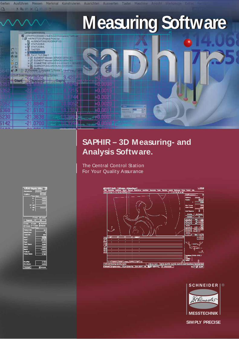
SAPHIR – 3D Measuring- andAnalysis Software.
The Central Control StationFor Your Quality Assurance
SIMPLY PRECISE

The interface between humanand machine.
The view of sophisticated software tools as an essential link betweenhumans and their machines has guided the development of the 3Dmeasuring software SAPHIR from its earliest stages of design. Theseamless integration of the software into existing environmentsmore than ever testifies to its outstanding flexibility and adaptability.
For fifteen years, our forward-looking team of expert developershas been continuously dedicated to preparing SAPHIR for evolvingmarket requirements. Thanks to the reliable integration of ever-increasing functions, SAPHIR is fit for the future. It counts amongthe most renowned products for this field of application worldwide.
Among the main appeals of the measuring software, which hasreceived certification from the German National MetrologyInstitute PTB, are its clear architecture and easy operation. Thanksto its specific structure in terms of control, sensor technology anddata exchange, SAPHIR is multi-sensor capable and can also managemultiple control axes.
Lower costs thanks to multi-sensor technology
Attention to detail is crucial in the world of measurement because detail has a cumulative effect onthe accuracy of the whole. This is why the selection of the proper sensor is so essential for efficientmeasurement.
The 3D measuring software SAPHIR, which has been specially designed for this type of fine-tunedapplication, uniquely combines the use of a wide range of different sensors in one software package.No matter whether you wish to measure parts manufactured to loose or tight tolerances, parts withmatte or glossy surfaces, light or dark parts, the sensor which best suits your measurement needs isalways available. An integrated black and white or colour camera for measurements in incident ortransmitted light with programmable 16-sector incident illumination, touch-trigger or scanning pro-bes, optionally equipped with a swivel head system, or a high-precision measuring laser system willallow you to use your measuring machine in a targeted and cost-effective way.
All sensors can be automatically swapped and inserted during the measuring process without stop-ping or changing the selected programme.
One software solution for all types of sensor: efficient and user-friendly because human attention canbe fully dedicated to the measuring task proper.
3D Measuring- andAnalysis Software SAPHIR
Measuring head of PMSSeries with CCD matrixcamera, touch probe TP200,which moves back afterusing and conoscopic measuring laser.

3
Thanks to the wide range of import formats, even complex shapes can be easily programmed.
The perfect fit!
In the rear too short, in the front too long – thosegloomy days are over: Thanks to the 2D and 3DBestFit feature, your measurements will always“cut a good figure”. The actual measured valuesare optimally aligned with the 2D target valuesdelivered in DXF and IGES format. The best possibleexploitation of tolerances is thus guaranteed.Optionally, formats such as CATIA, AutoCAD(DWG), 3D Studio (.3ds), Lightwave (.lwo), Step(.stp, .step), Raw Triangles (.raw), STL (.stl), VDA(.vda), VRML (.vrml, .wrl), Wavefront (.obj), PDF(.pdf, .ai, .eps) as well as TXT (.txt) can be processed.
Paperless quality assurance
You know of it from hearsay, but have never seenit implemented? Then don’t miss out on yourchance. Automated reporting ensures documen-ted quality in each measuring operation, withoutthe hassle of paper! The results can immediatelybe sent via network to the predefined server loca-tions, where they can be stored in the form of PDFfiles for further processing.Automated reporting includes:
• First sample test report• Graphic record• Inspection record
After each measuring operation you are provided with paperless, environmentally friendly quality documentation as a PDF file.
The accurate point graphic depicts an exact representation ofcritical workpiece areas.

4
Tool barThe tool bar offers typically arrangedfunctions such as “Open”, “Save”,“Print”, “Copy” etc. that are knownfrom other Windows applications.
Coordinate system of the workpieceSpatially disoriented? – No way! Onelook, and you know where exactly yourworkpiece is in relation to the measuringmachine.
To illustrate this, we composed the 3D- and 2D-image in one screen-design.
Control barThe control bar displays selected iconsfor quick access. These may include:
Displacement of the measuring machine’sarm by mouse control, virtual workpieceillumination, freely selectable workpieceviews, or whatever you consider impor-tant features to speed up your workflow.
IndexHere you will find the tabs relevant for the respective programme status.They include:
• Elements - Display of all measured geometrical elements in list form• Protocol - set of measurement records• Points - Depending on the elements measured, a list of their respective measuring points is displayed• LearnProg - The suitable programme is recorded during manual measurement• ProbeCfg - List of calibrated probe and stylus data.
Title barThe expanded title bar displays not only the usual information, butalso provides data regarding the workpiece, the working position ofthe sensor and the selected mode.

5
Status barClear display of the current programme status.
Virtual workpiece positionIt is up to you to decide how youwant to move the workpiece: eitherby button press or mouse click. Use the right-hand mouse button torotate the workpiece, the left-handmouse button to push it, and pressboth mouse buttons simultaneouslyfor zooming.
View port2D or 3D representation of the work-piece or measuring process, depen-ding on the selected active probe.
Task barSAPHIR is, of course, capable of multi-tasking. Use the task bar to change to another opened programme at any time.
Probe informationJust one look, and all relevant parame-ters on the active probe, the stylusused and probe configuration are available.
Position displayInformation about the current probeposition for a maximum of 5 axes.
Menu barSAPHIR offers several menus allowing access to essential programme functions. The various pull-down menus lead to further features.

Fast familiarisation with the measuring software SAPHIRthanks to shopfloor-oriented measuring
• Results are available in only a few steps.• Intuitive operator guidance facilitates familiarisation with the software.• Automatic measuring of unknown contours.• Automatic recognition of circles and straight lines.• Clearly structured user interface for convenient measurement.• Fast generation of automatic measuring programmes.• No previous programming knowledge is required for programme creation.• Measuring programmes are displayed in plain text tree format. • Macros, sub-programmes as well as loop programming features facilitate
programme compilation for continuous measurement tasks.• All elements can be represented graphically; individual elements
can be linked up with each other so that new, composite elements can be constructed.
• Graphic and inspection record.
Fast, precise and accurate in all circumstances – thanks to the contour
recognition feature, workpiece dimensions can be determined even
without a drawing.
Travelling unknown paths …
… may prove a risky venture, yet not so for SAPHIR: The 3D measuring softwareautomatically recognises and scans not only known, but also unknown contours. 2D contours are scanned by means of a camera, 3D contours with a scanningprobe – a powerful tool that is complemented by 2D and 3D BestFit features.
7
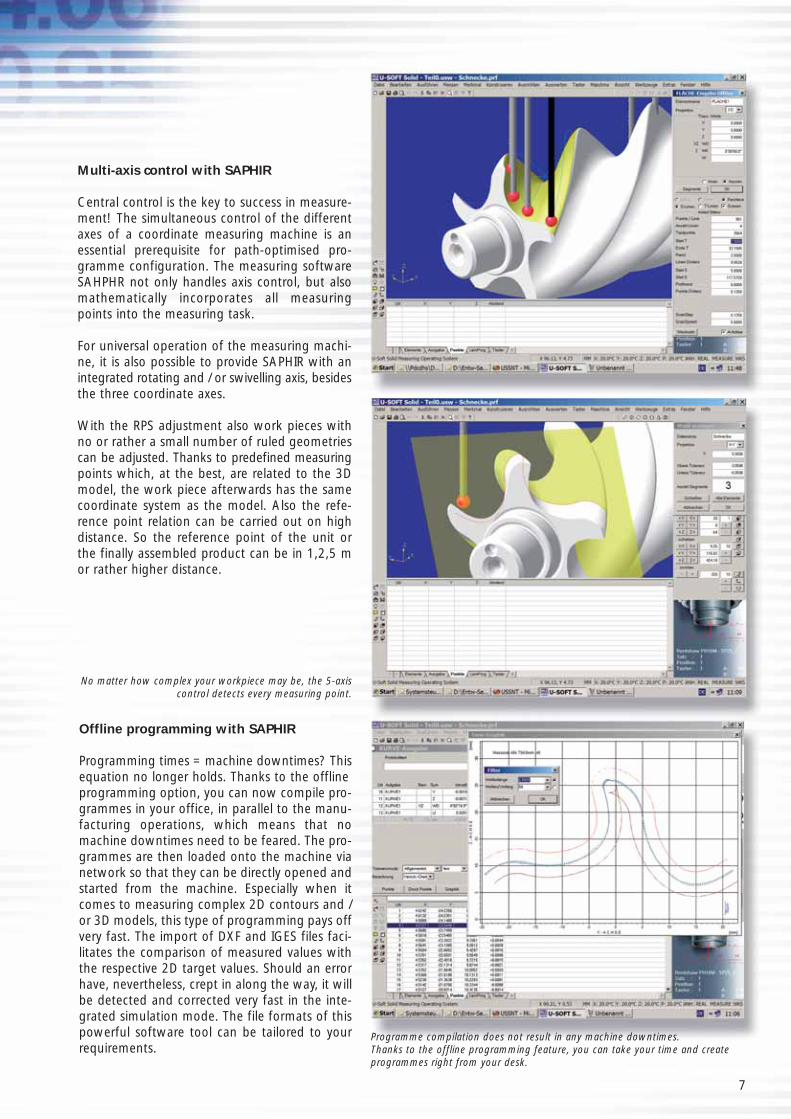
Offline programming with SAPHIR
Programming times = machine downtimes? Thisequation no longer holds. Thanks to the offline programming option, you can now compile pro-grammes in your office, in parallel to the manu-facturing operations, which means that nomachine downtimes need to be feared. The pro-grammes are then loaded onto the machine vianetwork so that they can be directly opened andstarted from the machine. Especially when itcomes to measuring complex 2D contours and /or 3D models, this type of programming pays offvery fast. The import of DXF and IGES files faci-litates the comparison of measured values withthe respective 2D target values. Should an errorhave, nevertheless, crept in along the way, it willbe detected and corrected very fast in the inte-grated simulation mode. The file formats of thispowerful software tool can be tailored to yourrequirements.
No matter how complex your workpiece may be, the 5-axiscontrol detects every measuring point.
Programme compilation does not result in any machine downtimes. Thanks to the offline programming feature, you can take your time and createprogrammes right from your desk.
Multi-axis control with SAPHIR
Central control is the key to success in measure-ment! The simultaneous control of the differentaxes of a coordinate measuring machine is anessential prerequisite for path-optimised pro-gramme configuration. The measuring softwareSAHPHR not only handles axis control, but alsomathematically incorporates all measuringpoints into the measuring task.
For universal operation of the measuring machi-ne, it is also possible to provide SAPHIR with anintegrated rotating and / or swivelling axis, besidesthe three coordinate axes.
With the RPS adjustment also work pieces withno or rather a small number of ruled geometriescan be adjusted. Thanks to predefined measuringpoints which, at the best, are related to the 3Dmodel, the work piece afterwards has the samecoordinate system as the model. Also the refe-rence point relation can be carried out on highdistance. So the reference point of the unit orthe finally assembled product can be in 1,2,5 mor rather higher distance.

Standard features ( �) and Options ( �)
� Element linkage and construction of composite elements*, also at the graphical level � Processing of theoretical elements� Intersections (polygon) � Integrated CAD functions� Flexible setup of inspection records� First sample test report after VDA, Version I & II� 2D CAD data import/export (DXF, IGES)� Graphic and inspection record � Graphical representation of elements*� Automatic vertex generation� Administration of measuring sensors such as optics, laser system, touch-trigger and scanning probes� Spatial alignment� Axial alignment� Alignment of the rotation axis� Shape and position tolerances� Pitch measurement� Macro and sub-programme technology� Loops and conditional jumps� Integrated tolerance table� Programme simulation� Probe calibration with readout of calibration quality� Eight different image processing probes� Debug and editing functions for programme optimisation� Coordinate system memory� Fine positioning via mouse functions� SPC interface for ASCII, Excel and qs-STAT, Böhme & Weihs, customer-specific about layout function� Automatic following of known and unknown contours� Offline programming with CAD linkup� SPC module for quality management system evaluation� User administration� Measurement of palletised workpieces� 2D digitisation and BestFit function� 3D digitisation and BestFit function� User access and managementsoftware in compliance with 21 CFR part 11
by the FDA (Food and Drug Administration)� Parameter programming� CAD import: CATIA, AutoCAD (DWG), 3D Studio (.3ds), Lightwave (.lwo), Step (.stp, .step), VRML (.vrml,.wrl),
Raw Triangles (.raw), STL (.stl), VDA (.vda), Wavefront (.obj), PDF (.pdf, .ai, .eps) as well as TXT (.txt)
* Elements are points, straight lines, circles, cones, sphere, cylinder, plane, torus, ellipse.
Programme Characteristics
Dr. Heinrich Schneider Messtechnik GmbH · Rotlay-Mühle · 55545 Bad Kreuznach · GermanyTel. +49 (0) 671 291 02 · Fax +49 (0) 671 291 200 · [email protected] · www.dr-schneider.de Te
chni
cal m
odifi
catio
ns r
eser
ved
– 04
.200
9/W
D/R
DL
Network-capable and compatible
Windows is among today’s most widely used operation systems. The SAPHIR measuring software puts this benefit to use in a unique way; it is fully network-capable and easily communicates with CAD or SPC systems. The interfaces required for these systems are already provided in the SAPHIR standard version.

Series PMS LLSeries PMS LL
Ultra-Accurate 3D Multi-Sensor Portal Measuring Machines
SIMPLY PRECISE
High-end device for sophisticated measurement tasks
Accurate
Precise
Flexible
Fast
The products of the series PMS LL offer a perfect blend of maximum precision,outstanding flexibility and optimum measuring speed.
Series PMS LL
Ultra-accurate 3D multi-sensorportal measuring machines
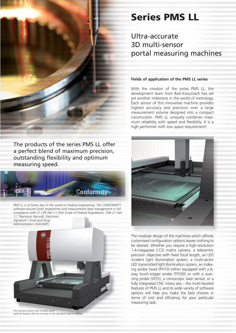
Fields of application of the PMS LL series
With the creation of the series PMS LL, thedevelopment team from Bad Kreuznach has setyet another milestone in the world of metrology.Each sensor of this innovative machine provideshighest accuracy and precision over a largemeasurement volume designed into a compactconstruction. PMS LL uniquely combines maxi-mum reliability with speed and flexibility. It is ahigh performer with low space requirement!
The modular design of the machines which affordscustomised configuration options leaves nothing tobe desired. Whether you require a high-resolution1.4-megapixel CCD matrix camera, a telecentricprecision objective with fixed focal length, an LEDincident light illumination system, a multi-sectorLED transmitted light illumination system, an index-ing probe head (PH10) either equipped with a 6-way touch-trigger probe (TP200) or with a scan-ning probe (SP25), a conoscopic laser sensor, or afully integrated CNC rotary axis – the multi-facetedfeatures of PMS LL and its wide variety of softwareoptions will help you make the best choices interms of cost and efficiency for your particularmeasuring task.
PMS LL is at home also in the world of medical engineering: The CONFORMITYsoftware ensures both programme and measurement data management in fullcompliance with 21 CFR Part 11 FDA (Code of Federal Regulations, Title 21 Part11 “Electronic Records, Electronic Signature”; Food and Drug Administration USA/GMP).
The machine shown here includes some optional features that are not part of the standard scope of delivery

For more detailed information, please visit our website at: www.dr-schneider.de
Optional features of the PMS LL series
• 5-axis computer numerical control (CNC)• Renishaw touch-trigger probe TP200
with SCR200 stylus change rack• Motorised indexing probe head PH10 allowing
workpiece positioning at a precise angle or interval of rotation
• Segmented (multi-sector) LED incident light • Coaxial scanning point laser• Active temperature compensation function for
the workpiece and the machine• 2D and 3D digitisation/BestFit
Special features of the PMS LL series
• Air-bearing guideway system in all axes• Torsion-resistant, high-precision granite construction• Total height of 2300mm affording 600mm
of Z axis travel
Benefits of the PMS LL series
• Well-conceived modular system• Compact design• Customised measuring ranges upon request
Optimum space utilisation: Maximum measuringrange meets minimum floor space. The ergonomi-cally designed workstation also offers plenty ofbenefits because it integrates the control cabinetof the machine, thus helping to save even morespace and cost.
The machine shown here includes some optional features that arenot part of the standard scope of delivery.
Standard features of the PMS LL series
• 3-axis computer numerical control (CNC)• 1.4-mexapixel CCD camera• Telecentric precision objective• Telecentric LED transmitted light
illumination system• High-performance software package
SAPHIR

Model
Measuring range mm
Objective1)
Magnification
Image field mm
Working distance mm
Resolution mm
Travel speed max. mm/s
Acceleration max. mm/s
Positioning accuracy µm
Workpiece weight max.
on glass plate alone kg
with granite stage support kg
Length measurement uncertainty 2)
DIN EN ISO 10360-2
VDI/VDE 2617
Our measurement is based on
Dimensions mm
Control cabinet mm
Workstation desk 130 mm
Weight kg
Power supply
PMS 600 LL PMS 700 LL PMS 900 LL PMS 1200 LL
X 600 X 700 X 900 X 1200
Y 600 Y 700 Y 700 Y 1200
Z 600 Z 600 Z 600 Z 600
1.0x
5.6x4.2
190
0.0001
100
400
0.1
20
100
E1 = (0.9+L/600 mm)µm Measuring length L in mm
E2 = (1.2+L/500 mm)µm Measuring length L in mm
E3 = (1.9+L/400 mm)µm Measuring length L in mm
� = 1,0 -̂ objective 1.0x (image field 5.6 x 4.2mm) – the measurement uncertainty value is valid for the indicated image field
W 1750 W 1850 W 2050 W 2350
D 2700 D 2800 D 2800 D 3800
H 2350 H 2350 H 2350 H 2350
1300 x 900
4500 5500 7500 10500
220-240VAC, 50-60Hz, 1kW
Technical Specifications of the PMS LL Series
Tech
nica
l mod
ifica
tions
res
erve
d –
04.2
010/
AV
/RD
L
Dr. Heinrich Schneider Messtechnik GmbH · Rotlay-Mühle · 55545 Bad Kreuznach · GermanyTel. +49 (0) 671 291 02 · Fax +49 (0) 671 291 200 · [email protected] · www.dr-schneider.de
1) Other objectives are available upon request2) Ambient conditions 20 °C ± 1K, Temperature gradient �th = 1K/h, �td = 4.0 K/d, measured with a calibrated standard; 15…35 °C,
we recommend use of an air-conditioned control cabinet if ambient temperatures are >25°C.
Measuring and analysis software SAPHIREfficient workflows are essential to successful business operations, and so isconsistent cost optimisation. It is, therefore, not by coincidence that choosingthe right machinery with the right software is a key part of any corporatestreamlining process. Since “Schneider” is the German word for “tailor”, youcan rightly conclude that SAPHIR is a truly “tailor-made” measuring softwarethat leaves nothing to be desired: from “A” as in “axis alignment” to “Z” asin “zero-point administration” – SAPHIR is a valuable resource with invaluablefeatures. For further information, please request our free “SAPHIR” brochure.

Digital Projector DP Digital Projector DP
Digital Projector for Fast and EasyMeasurement and Comparison of 2D Workpiece Contours
SIMPLY PRECISE

DP 200
200 x 100
60
1.5x 1.0x 0.5x 0.33x 0.25x 0.20x
62-fold 41-fold 21-fold 14-fold 10-fold 8-fold
4.3x3.4 6.5x5.2 13.2x10.5 20.0x16.0 26.5x21.2 33.0x26.5
20
W=780 D=570 H=700
80
220-240VAC, 50-60Hz, 1kW
Model
Measuring range mm
X-Y
Z
Objective
Magnification monitor mm
Image field mm
Workpiece weight max. kg
Dimensions 1) mm
Weight kg
Power supply
1) Height incl. touch screen
Technical Specifications of Digital Projector DP Te
chni
cal m
odifi
catio
ns r
eser
ved
– 04
.201
0/A
V/R
DL
Dr. Heinrich Schneider Messtechnik GmbH · Rotlay-Mühle · 55545 Bad Kreuznach · GermanyTel. +49 (0) 671 291 02 · Fax +49 (0) 671 291 200 · [email protected] · www.dr-schneider.de
Your benefit
• Integrated overlays, e.g. crosshairs and concentric circles• User-definable elements such as radii, circles, chamfers,
angles• Reading in of DXF files on a scale of 1:1• Display of different drawing layers• Comparison processes complete within seconds• Intuitive user interface• Portable design• Available with different fixed objectives• LED incident light illumination system• No instruction required
Special features of DP
• DP software with CCD camera and touch screen PC• Digital scales in all travel axes• Upper cross slide with 4 T-grooves• Table-top design• Sturdy granite construction• High-precision measuring stage with
non-corroding frame
Digital Projector DP
For more detailed information, please visit our website at: www.dr-schneider.de
Fields of application of DP
The administration of templates and overlays takestime and money. The new digital projector develo-ped by Schneider Messtechnik combines the manyadvantages of the proven projector with the digitalimage processing and analysis. All you have to dois load your DXF drawing onto the screen and posi-tion it accurately over the image of your workpie-ce. Once the drawing is aligned with the workpie-ce, it will move in synchrony with table motion sothat the user always have in focus the relevant sec-tion of the drawing. Another key feature allows theuser to define circles, lines and angles directly atthe device, which ensures high-quality measure-ment at top speed. The device is of course alsoequipped with many other powerful functions, forexample with a feature for accurate edge detection.

Measuring ProjectorsMeasuring Projectors
Vertical and Horizontal Measuring Projectors
High-end projectors for the reliable measurement of:
Stamped parts
Plastic parts
Tools
Seals and gaskets
Turned parts
Profiles
Punches
Dies
Pipes and tubes
Shafts
… and many more
SIMPLY PRECISE

Measuring projectors
For vertical and horizontal measurement– available as bench-top or floor models
Thanks to an integrated edge sensor, an optional CCD matrixcamera and exactly defined measurement uncertainty values inaccordance with ISO 10360-2, these projectors ensure reliablemeasuring results both in the manufacturing environment and inthe measurement room.
Areas of use
State-of-the-art measuring projectors developed by Dr. Heinrich Messtechnik have come to play a promi-nent role in the field of metrology, setting new standards in terms of accuracy and precision. The wellthought-out rigid overall structure of the machines in tandem with standard feature Multicount 2000 andan ultra-accurate and precise edge sensor are an ideal technological combination and thus constitute awinning team when speed and precision are key on the shopfloor and in the measuring room. All projectors have been designed to provide easy and intuitive operation to a broad range of users. Sincethey allow measurement operations to be performed in close proximity to the manufacturing area, effi-ciency is maximised whilst idle times are greatly reduced. What better way could there be to save money?
Especially when it comes to measuring turnedparts, projector ST 360 H shows its particularstrengths: Simply place the object to be inspec-ted on the stage of the device vertically, andmeasurement can begin.
Outstanding benefit
• Easy measurement of heavy workpieces of up to 50 kg
Standard equipment
• 360 mm screen with engraved crosshairs(graticule)
• Edge sensor incorporated into the light path
• Transmitted and incident illumination, 150 Watt each, halogen bulbs with cold-light filter
• Beam deflection mirror for incident illumination
Optional features
• Incident illumination via four-core optical fibre with cold-light source
• Swivelling light arm for transmitted illumination
• Multicount 3000 (geometric readout with image analysis function) equipped with a CCD camera
• Dual-objective changer (nosepiece)For more detailed information, please visit our website at: www.dr-schneider.de
Horizontal MeasuringProjector ST 360 H
An ideal choice for reliable measurement of• turned parts• pipes/tubes• tools• shafts• and many
more
The picture includes some optional machine features that are not part of the standard scope of delivery.

Available options
• Measuring and analysis software SAPHIR in manual or CNC configuration
• Helix-type swivel option thanks to a pivot-mounted plate superposed on the measuring stage
• Multicount 3000 (geometric readout with image analysis function) equipped with a CCD camera
• Digital angle indicator• Further options are available upon request
Available accessories
• Centre support block• Precision spindle support block SK40 • Stop bracket • Precision vice• Adjustment plate ± 6°
Standard equipment
• 360 mm screen with crosshairs• Edge sensor integrated into the beam path• Transmitted and incident illumination, 150 Watt each,
halogen bulbs with cold-light filter• Beam deflection mirror for incident illumination
Additional standard equipment
• Triple revolving nosepiece for fast objective change
Outstanding benefits
• Quick adjustment of the measuring stage• Measuring range 300 x 200 mm
Vertical Measuring ProjectorST 360 V
An ideal choice for reliable measurement of• seals and gaskets• plastic parts• dies• profiles• and many
more
The picture includes some optionalmachine features that are not partof the standard scope of delivery.

Outstanding benefits
• Large-scale display of the workpiece
• Quick adjustment ofthe measuring stage
• Triple revolving nosepiece for fast objective change
Additional standard equipment
• Triple revolving nosepiece accommodating different objectives
• 600 mm screen with with engraved crosshairs (graticule)
• Incident illumination via two-core optical fibre and cold-light source
• Transmitted illumination with cold-light filter
Available options
• Multicount 3000 (geometric readout with image analysis function) equipped with a CCD camera
• Digital angle indicator• Laterally displaced lifting column and manual
swivelling axis SK50 for measurement of tools with large diameters
• Motorised adjustment of the 3 axes• Telecentric objectives from 5x to10x
magnification• Further options are available upon request
Available accessories
• Adjustment plate ± 6°• Standardised reference measuring plates• Darkening device• Pair of precision Vee blocks
Vertical Measuring ProjectorPMP 600 (Floor Model)
An ideal choice for reliable measurement of• stamped parts• profiles• punches• dies• tools• and many more
The picture includessome optional machine
features that are not part ofthe standard scope of delivery.
A laterally displaced lifting column in tandem with an
SK50 manual swivelling axis allow measurement of tools
with large diameters. A glass stage with an SK50 tool
holder, is, of course also optionally included in the scope
of delivery.

Outstanding benefits
• High acutance (sharpness of contours) for reliable measurement
• Smooth and easy operation• Consistent quality of measurement results• No readjustment required• Measurement of cylindrical and cubic work-
pieces with consistent accuracy and precision• Reproducible, repeatable and documentable
workpiece quality and measurement results• Measurement results can be recorded
immediately
Standard equipment
• Template holder• Protractor, rotatable through 360°, Nonius 1’• Needle-bearing supported X, Y, and Z axes• Transmitted and incident illumination• 0.001 mm resolution scales• Edge sensor integrated into the light path• Calibration to DIN EN ISO 10360-2
and VDI/VDE 2617• Digital readout with geometric functions
Multicount 2000• 2D calibration across the entire measuring
surface as a complement to the linear correction function
Options
• Motorised adjustment of all 3 axes• Multicount 3000 (geometric readout
with image analysis function) equipped with a CCD camera
• Digital angle indicator• Telecentric objectives• Readout computer equipped with measuring
and analysis software SAPHIR• Further options are available upon request
Accessories
• Darkening device• Rotary table• Precision vice• Pair of centre support blocks or spindle
support SK40/50• Roller block• Precision jaw chuck with angle indicator• Base cabinet• Further accessories are available upon request
Integrated edge sensor
An edge sensor built into the projector’s light path ensures reliable measuring results under any ambient light conditions.
Common features of all measuring projectors:

Dr. Heinrich Schneider Messtechnik GmbH · Rotlay-Mühle · 55545 Bad Kreuznach · GermanyTel. +49 (0) 671 291 02 · Fax +49 (0) 671 291 200 · [email protected] · www.dr-schneider.de
Type
Measuring range mm
Magnification
Image field mm
Working distance mm
Screen diameter mm
Projection accuracy
for transmitted light %
for incident light %
Distortion max. ‰
Resolution mm
Workpiece weight kg
on glass plate kg
Length measuring uncertainty1 1)
DIN EN ISO 10360-2, VDI/VDE 2617
Dimensions mm
Stage size mm
Weight kg
Electric power supply
ST 360 H ST 360 V PMP 600
250 x 150 300 x 200 250 x 125
10 20 50 100 5 10 20 50 100
36 18 7,2 3,6 100 50 25 10 5
115 97 53 45 258 134 128 90 45
360 360 600
0.10 0.10 0.08
0.15 0.15 0.10
0.1 0.1 0.2
0.0001
50
20 20
E1 = (2.5+L /75 mm)µm*
E2 = (2.8+L /75 mm)µm*
*Measuring length L in mm
W 1000** W 1000** W 1120**
D 1170 D 1000 D 1350
H 1115 H 1249 H 1850
**Inclusive of Multicount
500 x 135 520 x 325 520 x 325
230 270 480
220-240 VAC, 50-60Hz, 1kW
1) Prerequisites: Admissible ambient conditions 20 °C ± 1K, Temperature gradient �th = 0.5 K/h, �td = 4.0 K/d
Technical Specifications of the Measuring Projectors
Tech
nica
l mod
ifica
tions
res
erve
d –
12.2
009/
AV
/RD
L
Geometric readout with image analysis function Multicount 3000 (MC 3000)Digital readout MC 3000 is a powerful tool which for the first time combines in onedevice value recording and imaging functions: Measurement points obtained from aposition indicator are recorded, while a live image of the object to be measured is simultaneously displayed on the screen. The device unites in itself all the qualities ofMulticount 200/2000 along with the benefits of image processing, live imaging as wellas automatic edge detection and thus marks a new milestone in high-quality metrology.
Digital readout with geometric functions Multicount 200 (MC 200)and Multicount 2000 (MC 2000)Geometric elements of any type can be measured fast and with consistent reliability:Multicount 200/2000, which provides easy and intuitive operation, in conjunction witheither an optionally available outside edge sensor (MC 200) or with an edge sensor builtinto the projector’s beam path (MC 2000) ensures fast edge detection and offers everyuser smart analysis functions.