woollahra municipal council - · pdf fileroadworks, drainage and miscellaneous works standard...
TRANSCRIPT
WOOLLAHRA MUNICIPAL
COUNCIL
SPECIFICATION FOR
ROADWORKS, DRAINAGE AND MISCELLANEOUS
WORKS
February 2012
© JOHN NIXON ENGINEERING Pty Ltd
and
WOOLLAHRA MUNICIPAL COUNCIL
ROADWORKS, DRAINAGE AND MISCELLANEOUS WORKS Standard Specification Page i
WOOLLAHRA MUNICIPAL COUNCIL
WOOLLAHRA MUNICIPAL COUNCIL
SPECIFICATION FOR
ROADWORKS, DRAINAGE AND MISCELLANEOUS WORKS
February 2012
TABLE OF CONTENTS
1 APPLICATIONS OF SPECIFICATION .................................................................................................. 5
1.01 CERTIFYING OFFICER............................................................................................................ 5
1.02 THE PARTIES CARRYING OUT THE WORK ....................................................................... 5
1.03 DESIGNATION OF MATERIALS ............................................................................................ 6
1.04 DESCRIPTIONS OF THE WORKS AND OF WORK TO BE CARRIED OUT ...................... 6
2 COMPLIANCE WITH STANDARDS ..................................................................................................... 7
3 SCHEDULES OF TECHNICAL DATA ................................................................................................ 10
3.01 FILLING ................................................................................................................................... 10
3.02 CONCRETE ............................................................................................................................. 10
3.03 KERBS GUTTERS FOOTPATHS AND MEDIANS .............................................................. 11
3.04 ROADWORKS AND HARDSTANDINGS ............................................................................. 11
3.05 STORMWATER DRAINAGE ................................................................................................. 11
4 PRELIMINARIES .................................................................................................................................. 12
4.01 COORDINATION WITH CERTIFYING OFFICER AND WOOLLAHRA MUNICIPAL
COUNCIL ................................................................................................................................. 12
4.02 PROVISION FOR TRAFFIC ................................................................................................... 12
4.03 INSPECTION DURING MANUFACTURE ............................................................................ 13
4.04 INSPECTION, TESTING & REPORTING GENERALLY ..................................................... 13
4.05 QUALITY ASSURANCE TESTING & REPORTING ........................................................... 13
4.06 MATERIALS/WORK DESIGNATED FOR Q.A. REPORTING ............................................ 13
4.07 ENVIRONMENTAL MANAGEMENT .................................................................................. 14
4.08 OCCUPATIONAL HEALTH AND SAFETY MANAGEMENT ............................................ 14
5 SITE PREPARATION ............................................................................................................................ 16
5.01 GENERAL ................................................................................................................................ 16
5.02 REMOVAL OF TOPSOIL AND VEGETATION .................................................................... 16
5.03 SILTATION .............................................................................................................................. 16
5.04 PROTECTION OF EXISTING TREES ................................................................................... 16
6 EXCAVATION ...................................................................................................................................... 18
6.01 GENERAL ................................................................................................................................ 18
6.02 SAWCUTTING ........................................................................................................................ 18
6.03 EXCAVATION FOR FOUNDATIONS ................................................................................... 18
6.04 SHORING ................................................................................................................................. 18
6.05 UNDERGROUND SERVICES AND BUILDINGS ................................................................ 19
6.06 CONDITIONS BELOW GROUND ......................................................................................... 19
7 FILLING ................................................................................................................................................. 20
7.01 BACKFILLING ........................................................................................................................ 20
7.02 COMPACTED FILL ................................................................................................................. 20
7.03 FILLING AND BACKFILLING MATERIAL ......................................................................... 20
7.04 COMPACTION OF FILL AND BACKFILL ........................................................................... 20
8 CONCRETE WORKS ............................................................................................................................ 22
8.01 CONCRETE QUALITY ........................................................................................................... 22
8.02 MATERIAL STORAGE ........................................................................................................... 22
8.03 SAMPLING AND TESTING ................................................................................................... 22
ROADWORKS, DRAINAGE AND MISCELLANEOUS WORKS Standard Specification Page ii
WOOLLAHRA MUNICIPAL COUNCIL
8.04 FORMWORK ........................................................................................................................... 23
8.05 REINFORCEMENT ................................................................................................................. 24
8.06 CORE HOLES AND EMBEDMENTS .................................................................................... 25
8.07 CONCRETE WORKMANSHIP............................................................................................... 25
8.08 EMERGENCY MEASURES .................................................................................................... 26
8.09 JOINTS ..................................................................................................................................... 26
8.10 CONCRETE CURING AND PROTECTION .......................................................................... 27
8.11 DEFECTIVE CONCRETE ....................................................................................................... 27
8.12 SURFACE FINISHES .............................................................................................................. 28
9 KERBS, GUTTERS, FOOTPATHS, AND MEDIANS ......................................................................... 29
9.01 GENERAL ................................................................................................................................ 29
9.02 FOUNDATION ........................................................................................................................ 29
9.03 FORMWORK ........................................................................................................................... 29
9.04 CONCRETE FINISH ................................................................................................................ 29
9.05 JOINTS ..................................................................................................................................... 30
9.06 DRAINAGE OUTLETS ........................................................................................................... 30
9.07 CURING AND PROTECTION ................................................................................................ 30
9.08 TOLERANCES ......................................................................................................................... 30
10 ROADWORKS AND HARDSTANDINGS ........................................................................................... 31
10.01 GENERAL ................................................................................................................................ 31
10.02 PREPARATION OF SUB-GRADE ......................................................................................... 31
10.03 CRUSHED ROCK SUB-BASE AND BASE COURSES ........................................................ 31
10.04 CRUSHED OR RIPPED SANDSTONE SUB-BASE COURSES ........................................... 33
10.05 SAMPLES FOR TESTING ...................................................................................................... 34
10.06 SPREADING, COMPACTION AND TRIMMING ................................................................. 34
10.07 TRAFFIC LIMITATIONS ON BASES.................................................................................... 35
10.08 ASPHALTIC CONCRETE MIXES ......................................................................................... 35
10.09 PLACING ASPHALTIC CONCRETE ..................................................................................... 35
11 PAVING BRICKS, COBBLESTONES, AND INTERLOCKERS ........................................................ 36
11.01 GENERAL ................................................................................................................................ 36
11.02 EXCAVATION ........................................................................................................................ 36
11.03 BASE COURSE ........................................................................................................................ 36
11.04 BEDDING SAND ..................................................................................................................... 36
11.05 CRUSHED AND RE-CYCLED CONCRETE ......................................................................... 37
11.06 PAVING UNITS ....................................................................................................................... 37
11.07 LAYING PATTERN ................................................................................................................ 37
11.08 METHOD OF LAYING ........................................................................................................... 38
11.09 SERVICE BOXES, AREA LIGHTS, POLES, ETC. ............................................................... 38
11.10 TREE SITES ............................................................................................................................. 38
11.11 JOINTS ..................................................................................................................................... 39
11.12 COMPACTION ........................................................................................................................ 39
11.13 FILLING JOINTS ..................................................................................................................... 39
11.14 EDGE RESTRAINT ................................................................................................................. 40
12 STEELWORK ........................................................................................................................................ 41
12.01 MATERIALS - GENERAL ...................................................................................................... 41
12.02 SHOP DRAWINGS .................................................................................................................. 41
12.03 DIMENSIONS .......................................................................................................................... 41
12.04 FABRICATION ........................................................................................................................ 41
12.05 BOLT HOLES .......................................................................................................................... 42
12.06 SPLICES AND JOINTS ........................................................................................................... 42
12.07 WELDING ................................................................................................................................ 42
12.08 BOLTED JOINTS .................................................................................................................... 43
12.09 DELIVERY AND STORAGE .................................................................................................. 44
12.10 ERECTION ............................................................................................................................... 44
12.11 ATTACHMENT TO CONCRETE FOUNDATIONS .............................................................. 45
13 PROTECTIVE COATING FOR STEELWORK .................................................................................... 46
13.01 GENERAL ................................................................................................................................ 46
13.02 PREPARATION AND APPLICATION CONDITIONS ......................................................... 46
ROADWORKS, DRAINAGE AND MISCELLANEOUS WORKS Standard Specification Page iii
WOOLLAHRA MUNICIPAL COUNCIL
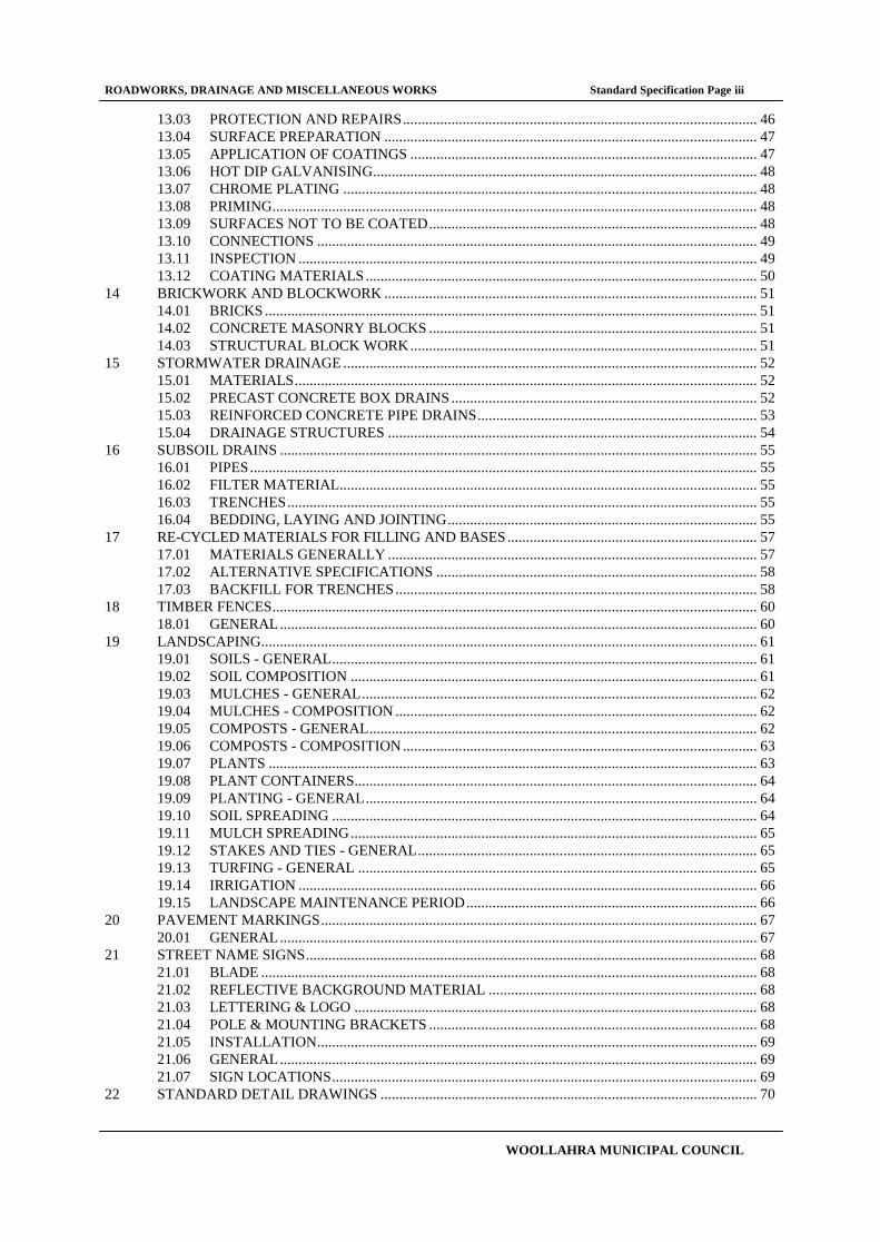
13.03 PROTECTION AND REPAIRS ............................................................................................... 46
13.04 SURFACE PREPARATION .................................................................................................... 47
13.05 APPLICATION OF COATINGS ............................................................................................. 47
13.06 HOT DIP GALVANISING ....................................................................................................... 48
13.07 CHROME PLATING ............................................................................................................... 48
13.08 PRIMING .................................................................................................................................. 48
13.09 SURFACES NOT TO BE COATED ........................................................................................ 48
13.10 CONNECTIONS ...................................................................................................................... 49
13.11 INSPECTION ........................................................................................................................... 49
13.12 COATING MATERIALS ......................................................................................................... 50
14 BRICKWORK AND BLOCKWORK .................................................................................................... 51
14.01 BRICKS .................................................................................................................................... 51
14.02 CONCRETE MASONRY BLOCKS ........................................................................................ 51
14.03 STRUCTURAL BLOCK WORK ............................................................................................. 51
15 STORMWATER DRAINAGE ............................................................................................................... 52
15.01 MATERIALS ............................................................................................................................ 52
15.02 PRECAST CONCRETE BOX DRAINS .................................................................................. 52
15.03 REINFORCED CONCRETE PIPE DRAINS ........................................................................... 53
15.04 DRAINAGE STRUCTURES ................................................................................................... 54
16 SUBSOIL DRAINS ................................................................................................................................ 55
16.01 PIPES ........................................................................................................................................ 55
16.02 FILTER MATERIAL................................................................................................................ 55
16.03 TRENCHES .............................................................................................................................. 55
16.04 BEDDING, LAYING AND JOINTING ................................................................................... 55
17 RE-CYCLED MATERIALS FOR FILLING AND BASES ................................................................... 57
17.01 MATERIALS GENERALLY ................................................................................................... 57
17.02 ALTERNATIVE SPECIFICATIONS ...................................................................................... 58
17.03 BACKFILL FOR TRENCHES ................................................................................................. 58
18 TIMBER FENCES .................................................................................................................................. 60
18.01 GENERAL ................................................................................................................................ 60
19 LANDSCAPING ..................................................................................................................................... 61
19.01 SOILS - GENERAL .................................................................................................................. 61
19.02 SOIL COMPOSITION ............................................................................................................. 61
19.03 MULCHES - GENERAL .......................................................................................................... 62
19.04 MULCHES - COMPOSITION ................................................................................................. 62
19.05 COMPOSTS - GENERAL ........................................................................................................ 62
19.06 COMPOSTS - COMPOSITION ............................................................................................... 63
19.07 PLANTS ................................................................................................................................... 63
19.08 PLANT CONTAINERS............................................................................................................ 64
19.09 PLANTING - GENERAL ......................................................................................................... 64
19.10 SOIL SPREADING .................................................................................................................. 64
19.11 MULCH SPREADING ............................................................................................................. 65
19.12 STAKES AND TIES - GENERAL ........................................................................................... 65
19.13 TURFING - GENERAL ........................................................................................................... 65
19.14 IRRIGATION ........................................................................................................................... 66
19.15 LANDSCAPE MAINTENANCE PERIOD .............................................................................. 66
20 PAVEMENT MARKINGS ..................................................................................................................... 67
20.01 GENERAL ................................................................................................................................ 67
21 STREET NAME SIGNS ......................................................................................................................... 68
21.01 BLADE ..................................................................................................................................... 68
21.02 REFLECTIVE BACKGROUND MATERIAL ........................................................................ 68
21.03 LETTERING & LOGO ............................................................................................................ 68
21.04 POLE & MOUNTING BRACKETS ........................................................................................ 68
21.05 INSTALLATION ...................................................................................................................... 69
21.06 GENERAL ................................................................................................................................ 69
21.07 SIGN LOCATIONS .................................................................................................................. 69
22 STANDARD DETAIL DRAWINGS ..................................................................................................... 70

ROADWORKS, DRAINAGE AND MISCELLANEOUS WORKS Standard Specification Page iv
WOOLLAHRA MUNICIPAL COUNCIL

ROADWORKS, DRAINAGE AND MISCELLANEOUS WORKS Standard Specification Page 5
WOOLLAHRA MUNICIPAL COUNCIL
ROADWORKS, DRAINAGE AND MISCELLANEOUS WORKS
1 APPLICATIONS OF SPECIFICATION
This Specification shall apply to work carried out on assets which are under or will revert to the ownership, care,
control or management of WOOLLAHRA MUNICIPAL COUNCIL in connection with:.
A. Work carried out by Contractors, subcontractors, suppliers etc. engaged or employed by Council
for such work, whether by Contract, Purchase Order or other means.
B. Maintenance work and Capital Works carried out by Council's direct labour organisation.
C. Work carried out by, or on behalf of, third parties on existing roads, footpaths and other assets
belonging to Council and/or the maintenance, reinstatement or creation of such assets or facilities
which belong to or will revert to the ownership, care, control or management of Council.
1.01 CERTIFYING OFFICER
For the purposes of this Specification the Certifying Officer is defined as:
A In the case of work carried out by Contractors, subcontractors, suppliers etc. engaged or employed by
Council, the Certifying Officer shall be the person nominated in writing to the respective contractor,
subcontractor or supplier etc. as exercising the role of the Certifying Officer. If a Superintendent is
appointed pursuant to a contract between Council and a contractor, subcontractor or supplier etc. the
Certifying Officer shall be the Superintendent.
B In the case of maintenance work and Capital Works carried out by Council's direct labour organisation, the
Certifying Officer shall be the delegated officer of Council.
C In the case of works carried out by, or on behalf of, third parties on existing roads, footpaths and other assets
belonging to Council and/or the maintenance, reinstatement or creation of such assets or facilities which
belong to or will revert to the ownership, care, control or management of Council, the Certifying Officer
shall be an Engineer or other professional accredited appropriately under the E.P. & A. Act.
1.02 THE PARTIES CARRYING OUT THE WORK
Where this Specification requires that materials, plant, equipment and/or labour shall be provided and/or expresses or
implies that work shall be carried out or provided or that activities shall be carried out, the party responsible for
providing the materials, plant, equipment and/or labour and carrying out the work shall be:
A In the case of work carried out in accordance with "1 A" above, the party shall be the contractor,
subcontractor, supplier etc.;
B In the case of maintenance work and Capital Works carried out in accordance with "1 B" above the party
shall be the respective Council employee responsible for such duties;
C In the case of works carried out in accordance with "1 C" above the party shall be the owner of the third
party Works associated with or carried out in connection with the respective work;
except in cases where it is clearly stated that respective goods, services etc. shall be provided by the Certifying
Officer or WOOLLAHRA MUNICIPAL COUNCIL.
In each case, the work carried out shall include the supply of all materials, plant, equipment and labour required for
the work.

ROADWORKS, DRAINAGE AND MISCELLANEOUS WORKS Standard Specification Page 6
WOOLLAHRA MUNICIPAL COUNCIL
1.03 DESIGNATION OF MATERIALS
Terms and/or trade names used to designate items or materials in the Documents are intended to define the quality
and general description of such items or materials, and are not intended to imply that they must be manufactured
and/or supplied by specific firms.
Items or materials supplied under alternative brand names or provided by alternative suppliers may be substituted if,
in the opinion of the Certifying Officer, the quality is not less that designated. In determining the suitability of
alternatives, the Certifying Officer will consider the basic material used in manufacturing the item or the finished
material, the quality of finish, durability and appearance (where considered appropriate). The Certifying Officer will
also determine whether an item or material proposed as an alternative is manufactured from basic materials and to a
standard of workmanship which is suitable for its purpose and is consistent with the nature and character of the
Works.
1.04 DESCRIPTIONS OF THE WORKS AND OF WORK TO BE CARRIED OUT
The Drawings and the Specification represent generally the forms, dimensions and descriptions of work to be carried
out.
The Specification sections are set out to "trades" or "classes of work" and shall apply individually and severally to all
aspects of work required for construction of any item or section of the Works.
Notwithstanding that some sections of the Specification or Drawings describe discrete or specific items of work or
parts of the Works, the work shall comply with the more general requirements of other sections in so far as they are
applicable. Any requirement therein shall be taken together with other documents describing the work, and any
ambiguity discrepancy or inconsistency shall be determined as required by the Certifying Officer.
ROADWORKS, DRAINAGE AND MISCELLANEOUS WORKS Standard Specification Page 7
WOOLLAHRA MUNICIPAL COUNCIL
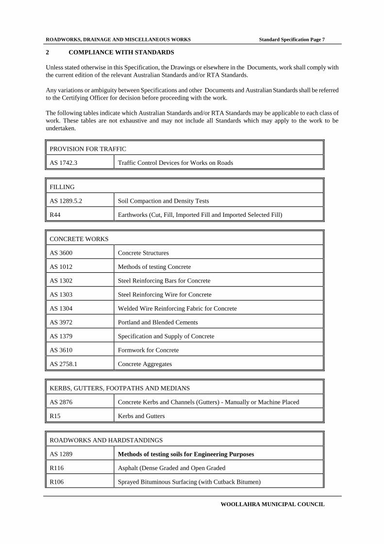
2 COMPLIANCE WITH STANDARDS
Unless stated otherwise in this Specification, the Drawings or elsewhere in the Documents, work shall comply with
the current edition of the relevant Australian Standards and/or RTA Standards.
Any variations or ambiguity between Specifications and other Documents and Australian Standards shall be referred
to the Certifying Officer for decision before proceeding with the work.
The following tables indicate which Australian Standards and/or RTA Standards may be applicable to each class of
work. These tables are not exhaustive and may not include all Standards which may apply to the work to be
undertaken.
PROVISION FOR TRAFFIC AS 1742.3
Traffic Control Devices for Works on Roads
FILLING AS 1289.5.2
Soil Compaction and Density Tests
R44
Earthworks (Cut, Fill, Imported Fill and Imported Selected Fill)
CONCRETE WORKS AS 3600
Concrete Structures
AS 1012
Methods of testing Concrete
AS 1302
Steel Reinforcing Bars for Concrete
AS 1303
Steel Reinforcing Wire for Concrete
AS 1304
Welded Wire Reinforcing Fabric for Concrete
AS 3972
Portland and Blended Cements
AS 1379
Specification and Supply of Concrete
AS 3610
Formwork for Concrete
AS 2758.1
Concrete Aggregates
KERBS, GUTTERS, FOOTPATHS AND MEDIANS AS 2876
Concrete Kerbs and Channels (Gutters) - Manually or Machine Placed
R15
Kerbs and Gutters
ROADWORKS AND HARDSTANDINGS AS 1289
Methods of testing soils for Engineering Purposes
R116
Asphalt (Dense Graded and Open Graded
R106
Sprayed Bituminous Surfacing (with Cutback Bitumen)

ROADWORKS, DRAINAGE AND MISCELLANEOUS WORKS Standard Specification Page 8
WOOLLAHRA MUNICIPAL COUNCIL
R107
Sprayed Bituminous Surfacing (with Polymer Modified Bitumen)
PAVING BRICKS, COBBLESTONES AND INTERLOCKERS AS 4455
Masonry Units and Segmental Pavers
AS 4456
Masonry Units and Segmental Pavers - Methods of Test
STEELWORK AS 4100
Steel Structures
AS 1554
Structural Steel Welding
AS 1627
Metal Finishing - Preparation and Pre-Treatment of Metal Surfaces
AS 1657
Fixed Platforms, Walkways, Stairways and Ladders - Design Construction
and Installation AS 2312
Guide to the Protection of Iron and Steel against Exterior Atmospheric
Corrosion
AS 1111
ISO Metric Hexagon Commercial Bolts and Screws
AS 1112
ISO Metric Hexagon Nuts, Including Thin Nuts, Slotted Nuts and castle Nuts
AS 1163
Structural Steel Hollow Sections
AS 1214
Hot Dipped Galvanised Coatings on Threaded Fasteners
AS 1252
High Strength Steel Bolts with Associated Nuts and Washers for Structural
Engineering AS 1397
Steel Sheet and Strip -Hot-Dipped Zinc Coated or Aluminium/Zinc Coated
AS 1553
Covered Electrodes for Welding
AS 1553.1
Low Carbon Steel Electrodes for Manual Arc Welding of Carbon Steels and
Carbon-Manganese Steels AS 1553.2
Low & Intermediate Alloy Steel Electrodes for Manual Metal Arc Welding of
Carbon Steels and Low and Intermediate Alloy Steels AS 1167.2
Welding and Brazing - Filler Metal for Welding
AS 1858
Electrodes and Fluxes for Submerged Arc Welding
AS 1594
Hot-Rolled Steel Flat Products
AS 2214
Certification of Welding Supervisors - Structural Steel Welding
AS 3678
Structural Steel Hot Rolled Plates, Floorplates and Slabs
AS 3679
Structural Steel
PROTECTIVE COATING

ROADWORKS, DRAINAGE AND MISCELLANEOUS WORKS Standard Specification Page 9
WOOLLAHRA MUNICIPAL COUNCIL
AS 2312
Guide to the Protection of Iron and Steel against Exterior Atmospheric
Corrosion AS 3750
Paints for Steel Structures
AS 1580
Paints and Related Materials - Methods of Testing
AS 4025
Paints for Equipment including Ships
BRICKWORK AND BLOCKWORK AS 1617
Refractory Bricks and Shapes
AS 3972
Portland and Blended Cements
AS 1672.1
Limes for Building
STORMWATER DRAINAGE AS 4058
Precast Concrete Pipes - Pressure and non-Pressure
AS 1741
Vitrified Clay Pipes and Fittings with Flexible Joints - Sewer Quality
AS 1646
Elastomeric Seals for Waterworks Purposes
AS 1597
Precast Reinforced Concrete Box Culverts
R11
Stormwater Drainage
R16
Precast Reinforced Concrete Box Culverts
R23
UPVC Pipes
SUBSOIL DRAINS R32
Sub-surface Drainage Materials
R33
Trench Drains
LANDSCAPING AS 4454
Compost, Soil Conditioners and Mulches
AS 1289
Methods of Testing Soils for Engineering Purposes
ROADWORKS, DRAINAGE AND MISCELLANEOUS WORKS Standard Specification Page 10
WOOLLAHRA MUNICIPAL COUNCIL
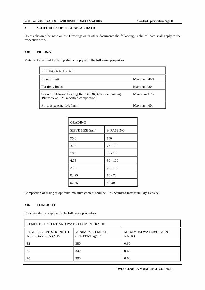
3 SCHEDULES OF TECHNICAL DATA
Unless shown otherwise on the Drawings or in other documents the following Technical data shall apply to the
respective work.
3.01 FILLING
Material to be used for filling shall comply with the following properties.
FILLING MATERIAL
Liquid Limit
Maximum 40%
Plasticity Index
Maximum 20
Soaked California Bearing Ratio (CBR) (material passing
19mm sieve 90% modified compaction)
Minimum 15%
P.I. x % passing 0.425mm
Maximum 600
GRADING
SIEVE SIZE (mm)
% PASSING
75.0
100
37.5
73 - 100
19.0
57 - 100
4.75
30 - 100
2.36
20 - 100
0.425
10 - 70
0.075
5 - 30
Compaction of filling at optimum moisture content shall be 98% Standard maximum Dry Density.
3.02 CONCRETE
Concrete shall comply with the following properties.
CEMENT CONTENT AND WATER CEMENT RATIO
COMPRESSIVE STRENGTH
AT 28 DAYS (F'c) MPa
MINIMUM CEMENT
CONTENT kg/m3
MAXIMUM WATER/CEMENT
RATIO 32
380
0.60
25
340
0.60
20
300
0.60

ROADWORKS, DRAINAGE AND MISCELLANEOUS WORKS Standard Specification Page 11
WOOLLAHRA MUNICIPAL COUNCIL
10
220
0.75
CONCRETE STRENGTH
ELEMENT
MINIMUM COMPRESSIVE
STRENGTH (F'c) Driveway
32 MPa
Footpath
25 MPa
Kerb and Gutter
25 MPa
Median
25 MPa
Stormwater Manholes (including covers)
25 MPa
Stormwater anchor blocks, encasement etc.
20 MPa
3.03 KERBS GUTTERS FOOTPATHS AND MEDIANS
The foundation under all Kerbs, Gutters, Footpaths and Medians shall be compacted to 95% Standard Maximum Dry
Density.
3.04 ROADWORKS AND HARDSTANDINGS
Roadworks and hard standings shall comply with the following properties.
COMPACTION REQUIREMENTS
LAYER
MINIMUM COMPACTION (STANDARD
MAXIMUM DRY DENSITY) Subgrade
100%
Sub base
100%
Base course
100%
3.05 STORMWATER DRAINAGE
Bases for Precast Concrete Box Drains shall be 25 MPa concrete reinforced with F72 reinforcing wire mesh.

ROADWORKS, DRAINAGE AND MISCELLANEOUS WORKS Standard Specification Page 12
WOOLLAHRA MUNICIPAL COUNCIL
4 PRELIMINARIES
4.01 COORDINATION WITH CERTIFYING OFFICER AND WOOLLAHRA MUNICIPAL COUNCIL
The party carrying out the work shall co-ordinate activities and co-operate with the Certifying Officer to ensure that
the work proceeds to their mutual satisfaction.
If the work requires some prior work to be completed by WOOLLAHRA MUNICIPAL COUNCIL, the Certifying
Officer shall be notified of any requirements not less that seven days before such completion is needed but in
sufficient time for the Certifying Officer to notify Council and for Council to have the work completed.
The Certifying Officer shall notify Council of any such requirements within four (4) working days of receiving
notification from the party carrying out the work.
4.02 PROVISION FOR TRAFFIC
Prior to commencing any work on the site a formal Risk Assessment of the impacts of the proposed work on traffic
and pedestrian flow shall be carried out and documented in accordance with OHS & R and other relevant
requirements.
Based on this risk assessment a Traffic Management Plan shall be developed. The Traffic Management Plan shall
include drawings showing the positions of all warning signs and traffic control devices and the directions of traffic
flow through and/or around the site for each stage of the work. The Traffic Management Plan shall be certified by a
person who has passed a RTA approved Traffic Control course. Proof of the certifiers qualifications and authority
shall be forwarded to the Certifying Officer.
The risk assessment and Traffic Management Plan shall be forwarded to the Certifying Officer at least fourteen (14)
days prior to any work commencing on the site.
Approval of the proposed Traffic Management Plan shall be obtained from the RTA, Police and the relevant road
Authority prior to implementing the plan. If the Certifying Officer or any of the approving authorities considers that
the extent or arrangement of signs and control devices shown or other aspects of the Traffic Management Plan is
inadequate, a new Traffic Management Plan shall be submitted, amended to satisfy the relevant requirements.
The approved Traffic Management Plan shall be implemented in accordance with the current edition of the relevant
Australian Standard. Control signs, temporary safety fencing and all safety facilities shall be installed as shown and
shall be maintained during each stage of the work.
In addition to the current edition of the relevant Australian Standard a minimum of one sand bag (or similar) shall be
placed on every barricade. Also as a minimum, the appropriate operational safety lighting shall be placed on every
second barricade or parawebbing post.
The implementation of the Traffic Management Plan shall be monitored daily and if it is found to be inadequate
immediate steps shall be undertaken to correct any faults or failures of the implementation. If the Certifying Officer
deems it necessary a revised Traffic Management Plan shall be submitted. Any revisions to the Traffic Management
Plan are subject to the same approvals as the original Traffic Management Plan.
If the Certifying Officer advises that he is of the opinion that a danger exists due to the inadequacy of warning signs,
barricades or other safety devices or due to procedures for control of traffic, supplementary signs, barricades or safety
devices and/or procedures as necessary shall be put in place immediately to overcome the danger.
Access for property owners in the vicinity of the site shall be maintained at all times and all owners whose access is
interrupted by work shall be consulted prior to work commencing. Any interruptions shall be minimised and essential
interruptions shall be allowed only at times acceptable to the owners.

ROADWORKS, DRAINAGE AND MISCELLANEOUS WORKS Standard Specification Page 13
WOOLLAHRA MUNICIPAL COUNCIL
4.03 INSPECTION DURING MANUFACTURE
Materials and equipment covered by this Specification may be subject to inspection by the Certifying Officer at any
time during construction at the manufacturer's works or those of his sub-contractors.
Should the Certifying Officer so direct, no materials or equipment shall be dispatched by manufacturers or suppliers
until notification, by the Certifying Officer, in writing that the inspection requirements have been satisfied.
4.04 INSPECTION, TESTING & REPORTING GENERALLY
All inspection and testing necessary to ensure that the work is carried out in accordance with this Specification shall
be carried out as the work proceeds, including all tests referred to in the Specifications or Drawings.
The Certifying Officer may waive requirements for testing of specific items of work or materials in cases where, in
the opinion of the Certifying Officer, the work is seen as complying with the requirements of the Specification and
further testing is not justified. However, no waiver shall apply unless provided in writing by the Certifying Officer
and any waiver shall only apply to the specific item of work set out in the written advice from the Certifying Officer.
The results of all inspections and tests shall be provided to the Certifying Officer as soon as practicable.
4.05 QUALITY ASSURANCE TESTING & REPORTING
Prior to commencing work on site or ordering any materials, a documented plan for Quality Assurance inspection,
testing and reporting shall be submitted to the Certifying Officer.
The plan submitted to the Certifying Officer shall include the names and positions of staff responsible for managing
Quality Assurance for work covered by this Specification and shall include sample forms for inspection, testing and
reporting the results of tests for both materials and workmanship.
Acceptance or rejection by the WOOLLAHRA MUNICIPAL COUNCIL, it's agents, or the Certifying Officer , of
inspection or test certificates provided under the Quality Assurance procedures shall in no way relieve the responsible
party from fulfilling all or any of their obligations under the Specification.
Tests and test certificates carried out or provided pursuant to the Specification generally and which have been
included in support of Quality Assurance programme shall have the same effect (if any) on obligations as if they were
carried out independently of the Quality Assurance programme.
4.06 MATERIALS/WORK DESIGNATED FOR Q.A. REPORTING
The responsible party is encouraged to make use of the Quality Assurance programme which is implemented for the
Works, by designating a broad range of materials and workmanship and providing corresponding inspection and test
reports regularly to the Certifying Officer, as evidence of compliance of the work with the requirements of the
Specification.
The minimum requirements of materials and work to be inspected, tested and reported upon, under the Q.A. reporting
programme for this Specification, are as follows:
Materials: Backfilling materials
Pipes, rubber rings & jointing compounds
Concrete
Road sub-base and base materials.
Workmanship: Formwork ready for inspection
Pipes laid ready for inspection
Compaction of backfill

ROADWORKS, DRAINAGE AND MISCELLANEOUS WORKS Standard Specification Page 14
WOOLLAHRA MUNICIPAL COUNCIL
Compaction of sub-grade, sub-base, base and base courses for roads,
hardstandings and other pavements.
4.07 ENVIRONMENTAL MANAGEMENT
Prior to commencing any work on the site a formal Risk Assessment of the impacts of the proposed work on the
environment shall be carried out and documented in accordance with EPA and other relevant requirements.
Based on this risk assessment an Environmental Management Plan shall be developed. The Environmental
Management Plan shall be developed in accordance WOOLLAHRA MUNICIPAL COUNCIL guidelines and the
requirements of the EPA and other relevant authorities. The Environmental Management Plan shall include drawings
showing the positions of all environmental control devices for each stage of the work.
The risk assessment and Environmental Management Plan shall be forwarded to the Certifying Officer at least
fourteen (14) days prior to any work commencing on the site. If the Certifying Officer or any of the approving
authorities considers that the extent or arrangement of environmental control devices shown or other aspects of the
Environmental Management Plan is inadequate, a new Environmental Management Plan shall be submitted, amended
to satisfy the relevant requirements.
The Environmental Management Plan shall be implemented in accordance with the requirements of the EPA and
other relevant authorities. Environmental control devices shall be installed as shown and shall be maintained during
each stage of the work.
The implementation of the Environmental Management Plan shall be monitored daily and if it is found to be
inadequate immediate steps shall be undertaken to correct any faults or failures of the implementation. If the
Certifying Officer deems it necessary a revised Environmental Management Plan shall be submitted.
If the Certifying Officer advises that he is of the opinion that a danger exists due to the inadequacy of environmental
control devices or due to procedures for control of environmental risks, supplementary environmental control devices
and/or procedures as necessary shall be put in place immediately to overcome the danger.
All requirements as set out by the appropriate regulations including the Clean Waters Act, the Environmental
Protection Authority and Local Government shall be met.
4.08 OCCUPATIONAL HEALTH AND SAFETY MANAGEMENT
Prior to commencing any work on the site a formal Risk Assessment covering all potential impacts to the health and
safety of workmen and the public shall be carried out and documented in accordance with WorkCover guidelines.
Based on this risk assessment an OHS & R Management Plan shall be developed. The OHS & R Management Plan
shall be developed in accordance with WorkCover guidelines and the requirements of the Construction Safety Act
and other relevant requirements.
The risk assessment and OHS & R Management Plan shall be forwarded to the Certifying Officer at least fourteen
(14) days prior to any work commencing on the site. If the Certifying Officer considers that the OHS & R
Management Plan is inadequate, a new OHS & R Management Plan shall be submitted, amended to satisfy the
relevant requirements.
The Management Plan submitted shall include the names of managers, supervisors and field staff responsible for
maintaining compliance with the Plan and all relevant legislative requirements. Details of training, certificates and/or
qualifications for all such personnel shall be included.
The plan submitted shall include for at least one ganger or supervisor who is employed on the site full time to be
responsible for ensuring that all requirements of the Plan and all relevant legislative requirements are implemented.
The plan shall allow for periodic reports to be submitted to and countersigned by the relevant Manager. These reports
shall be submitted regularly to the Certifying Officer.

ROADWORKS, DRAINAGE AND MISCELLANEOUS WORKS Standard Specification Page 15
WOOLLAHRA MUNICIPAL COUNCIL
Neither the submission of an OHS & R plan nor its acceptance by either the Certifying Officer or WOOLLAHRA
MUNICIPAL COUNCIL shall in any way relieve any other party of their OHS & R obligations.

ROADWORKS, DRAINAGE AND MISCELLANEOUS WORKS Standard Specification Page 16
WOOLLAHRA MUNICIPAL COUNCIL
5 SITE PREPARATION
5.01 GENERAL
All existing foundations, concrete slabs on ground and other structures or obstructions on the site shall be demolished
except for specific structures which are designated herein or on the drawings as to remain.
In the case of structures designated to remain on site, damage thereto during construction of the works shall be made
good to the satisfaction of the Certifying Officer.
All existing services are to be located and if necessary disconnected prior to commencing site preparation and there
shall be no damage to water, drainage, electricity, telephone, gas, parking meter or other services which are in use or
are required by the owners of the services.
All waste/debris etc. from the site shall be disposed of to a legal dump site. The Certifying Officer may seek written
confirmation that all waste/debris etc has been disposed of accordingly. All waste/debris etc that is recyclable shall
be recycled or sent to a suitable site for recycling.
5.02 REMOVAL OF TOPSOIL AND VEGETATION
Topsoil and vegetation shall be removed, stumps grubbed out and the holes backfilled and compacted as specified
under backfill, except in cases where the area is to be generally excavated to a level below the stumps.
Areas designated in the documents as not to be cleared, trees which have to be preserved, and natural surfaces which
are to remain as natural surfaces at completion of the Works, shall be protected from damage during demolition and
throughout the course of the work.
Topsoil suitable for use in landscaping may be stockpiled on site for later use if there is sufficient room on site and
landscaping is included in the Works or if landscaping by others is proposed. Stockpiles shall be maintained tidy. Silt
and soil shall be prevented from washing down on the site, onto surrounding areas, or into drains, etc.
Topsoil or other material remaining in stockpiles at the conclusion of the Works shall be compacted, trimmed and
grassed in accordance with the Landscape Works section of this Specification. Surplus topsoil shall be removed from
site and disposed of as for disposal of waste/debris etc described in the GENERAL section above.
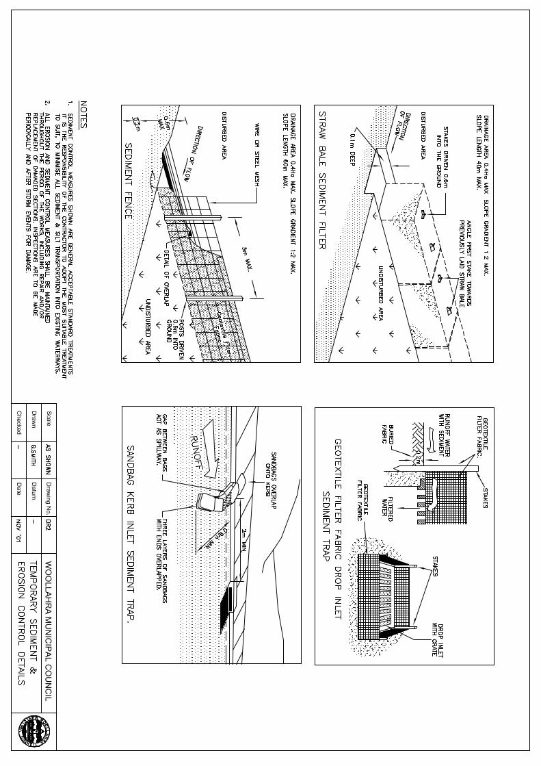
5.03 SILTATION
Siltation and sediment control devices shall be installed to all areas which may be subject to erosion.
All requirements as set out by the appropriate regulations including the Clean Waters Act, the Environmental
Protection Authority and Local Government shall be met in regard to the control of sediment and siltation that would
otherwise run off the site.
5.04 PROTECTION OF EXISTING TREES
Existing trees specified or shown on the drawings as not to be removed shall be protected from all damage during the
currency of the work . Clarification shall be sought from the Certifying Officer as to the status of those trees not
specified or shown as not to be removed on the drawings prior to the commencement of work.
Bulk materials and harmful materials including oil, waste concrete, clearings, boulders and the like shall not be
stored, stockpiled, dumped or otherwise placed under or near trees. Spoil from excavations shall not be placed against
tree trunks, even for short periods and wind blown materials such as cement shall be prevented from harming trees
and plants.
Stays, guys and the like shall not be attached to trees and tree bark shall not be damaged in any way.

ROADWORKS, DRAINAGE AND MISCELLANEOUS WORKS Standard Specification Page 17
WOOLLAHRA MUNICIPAL COUNCIL
When working near trees topsoil shall not be removed from within the drip line of trees unless otherwise specified. If
it is necessary to excavate within the drip line, hand methods shall be utilised such that root systems are preserved
intact where possible. The duration of open excavations under tree canopies shall be negotiated with the Certifying
Officer at the time of the excavation.
Tree roots exceeding 50mm nominal diameter shall not be cut. Where it is necessary to cut tree roots, a saw or similar
means shall be used such that the cutting does not unduly disturb or rock the remaining root system. Immediately after
cutting, an appropriate bituminous fungicidal sealant shall be applied to the cut to prevent the incursion of rot and
disease.
Backfilling to excavations around tree roots shall be with the topsoil mixture as specified in the LANDSCAPE
WORKS section of this Specification. The backfill is to be placed in layers, each of 150mm maximum depth,
compacted to a dry density similar to that of the surrounding soil. Backfill around tree trunks or over the root zone
shall not be above the original ground surface unless agreed to by the Certifying Officer . Immediately after
backfilling, the root zone surrounding the tree shall be thoroughly watered.

ROADWORKS, DRAINAGE AND MISCELLANEOUS WORKS Standard Specification Page 18
WOOLLAHRA MUNICIPAL COUNCIL
6 EXCAVATION
6.01 GENERAL
Excavation shall be to the lines and levels shown in the Drawings unless directed otherwise by the Certifying Officer.
Excavating plant and equipment shall be capable of performing the work to the satisfaction of the Certifying Officer .
If, in the opinion of the Certifying Officer, an appropriate area exists on the site suitable material may be stockpiled
and used for backfilling, provided that excess stockpiled material is disposed of when all backfilling is completed.
Surplus excavated material or material classified as unsuitable for use as fill elsewhere on the site shall be disposed of
to a legal dump site.
Excavations shall be trimmed to line and level by machine and/or by hand as necessary to produce profiles to the
accuracy required by the Drawings and/or Specification.
Over excavations in rock shall be backfilled with mass concrete of a strength similar to the rock.
In the case of excavations for roadworks and/or hardstandings, the area shall be compacted to the standard specified
in the relevant section of the Specification unless shown otherwise in the Drawings.
Surface drains shall be constructed and maintained around and within the site to control surface water and keep
excavations dry. Sumps shall be provided in low areas to collect water which cannot be controlled by drains.
Silt traps shall be provided to prevent the discharge of silt or debris to other property, into the environment or into
creeks, rivers, public drains or sewers.
Silt traps and sumps shall be pumped out continuously while ever water is present. Material in excavations softened
or damaged by flowing or ponded water shall be removed and reinstated as for over excavations.
6.02 SAWCUTTING
Should excavation be required in an area of concrete or asphalt, nominal sawcuts of 50mm depth shall be made in the
surface prior to excavation.
In the case of excavations for drainage Works, sawcuts shall be provided on both sides of the trench. For kerb and/or
gutter Works, sawcuts shall be provided around the perimeter of the area of pavement to be reinstated. Medians shall
be sawcut on the face of new median kerb alignment.
6.03 EXCAVATION FOR FOUNDATIONS
The exposed surface at the bottom of each excavation shall be adequately protected from disturbance by other
operations or by ground water or stormwater. Care shall be taken to avoid disturbance to adjacent material during
removal of any foundation material which has been disturbed, allowed to deteriorate or otherwise made unsuitable.
Material removed shall be replaced by selected material compacted as directed by the Certifying Officer.
Where footings are to be founded on rock, the rock surface shall be fully exposed to the depth and slope shown in the
Drawings, shaped to conform with the shape of the footings and left in a roughened condition. Any pockets of
unsuitable material in the bearing surface shall be removed and the pockets filled with mass concrete of a strength
similar to the rock.
Excavations shall be kept free from water until concrete is placed and formwork is removed, and until all concrete
below water level is sufficiently set or protected.
6.04 SHORING

ROADWORKS, DRAINAGE AND MISCELLANEOUS WORKS Standard Specification Page 19
WOOLLAHRA MUNICIPAL COUNCIL
Where necessary, excavations shall be supported and temporary supports provided to protect adjacent property,
services and other permanent construction, and to provide safe working conditions in and about the excavations.
Temporary supports shall be designed and constructed in accordance with the structural and safe working
requirements of the relevant local and statutory authorities. Working Drawings for temporary supports, conforming
with all relevant requirements shall be submitted to the Certifying Officer at least two weeks before it is intended to
erect the supports.
Temporary supports shall be removed from the excavations and excavations backfilled as construction progresses.
Removal shall be effected in such a way as not to damage any foundation or finished concrete.
6.05 UNDERGROUND SERVICES AND BUILDINGS
Existing buildings and underground services including telephone, parking meter cables, electricity, water supply,
stormwater, sewage, drainage, gas lines and traffic detectors shall be protected as required by the owner of the
respective services.
It shall be deemed that inquiries have been made with all authorities likely to have services in the area and buildings
in the area have been inspected and allowance has been made for all necessary protective works. Prior to the
commencement of any Excavation work documentary evidence shall be submitted to the Certifying Officer in order to
verify that such inquiries have been made and all necessary precautions have been taken and the temporary works are
in place.
Information provided by WOOLLAHRA MUNICIPAL COUNCIL regarding services on the site or regarding
adjacent buildings is provided as a guide only and does not relieve the responsible parties of their responsibility to
inform themselves as to conditions on, under or around the site .
In cases where services including drainage pipes are encountered during excavation, the Certifying Officer shall be
immediately notified and he may issue instructions as to what protection and/or concrete encasement is to be
provided.
Exploratory hand excavations shall be carried out in all areas where services may be encountered and excavation
around services shall be by hand as necessary to avoid damage to the services.
6.06 CONDITIONS BELOW GROUND
If rock or artificial obstructions are encountered the Certifying Officer may permit modifications to details to
mitigate some of the additional cost of excavating in rock or removing obstructions. Requests to amend details will
only be considered if such amendments do not adversely affect the structural strength, stability or the usefulness of the
Works.
If water is encountered, such sections of the site shall be dewatered as necessary to permit work to proceed as
required or such other measures as may be authorised by the Certifying Officer shall be undertaken.

ROADWORKS, DRAINAGE AND MISCELLANEOUS WORKS Standard Specification Page 20
WOOLLAHRA MUNICIPAL COUNCIL
7 FILLING
7.01 BACKFILLING
All timbering, bracing and rubbish of all descriptions shall be removed before or as backfill is placed.
Backfilling shall not commence until the Certifying Officer has been notified and, if he deems necessary, has
inspected the work.
Suitable granular materials only shall be used for backfill, except that non-granular materials such as silt and clay
may, at the Certifying Officer's discretion, be used for the upper 300 mm of backfill around exterior walls and
foundations.
All spaces excavated for foundations and not occupied by permanent work shall be backfilled to the surface of the
surrounding ground and compacted as specified or as directed by the Certifying Officer.
Backfill on all sides of piers and walls shall be carried up at the same level until ground surface is reached. No
backfill shall be placed against any abutment or wall until 14 days after placing the concrete unless authorised by the
Certifying Officer.
Selected material surplus from excavations may be used for backfilling trenches if permitted by the Certifying
Officer.
7.02 COMPACTED FILL
Areas to be filled shall be prepared, trimmed and finished as provided under the EXCAVATION section of this
Specification. Fill shall not be brought into fill areas until the Certifying Officer has been notified and, if he deems
necessary, has inspected the prepared areas.
Preparation shall include the removal of all topsoil, vegetation, debris, construction rubbish or materials or existing
obstructions which would create soft or hard spots under the fill such as to prevent even compaction of the fill.
7.03 FILLING AND BACKFILLING MATERIAL
Fill material shall be as specified in the Drawings or in Project Specific Specifications.
Backfill material shall be a selected predominately granular material which is capable of being compacted to the
necessary densities using equipment which is available on site and can work the material in close proximity to trench
walls, adjacent structures and the like.
If crushed and re-cycled concrete is used for fill and/or backfill, it shall comply with the description of the appropriate
Class of material in the Section RE-CYCLED MATERIALS FOR FILLING AND BASES in this Specification.
7.04 COMPACTION OF FILL AND BACKFILL
Material shall be spread in layers extending the full width of the excavation and each layer shall be compacted at
optimum moisture content to achieve the specified density. The finished thickness of each layer (after compaction)
shall be not greater than 150 mm.
Compaction shall be controlled by conducting field density and laboratory compaction tests on the filling material as
the compaction progresses. All testing is to be carried out by a NATA registered laboratory. The results of the
density testing must be submitted to the Certifying Officer.

ROADWORKS, DRAINAGE AND MISCELLANEOUS WORKS Standard Specification Page 21
WOOLLAHRA MUNICIPAL COUNCIL
Settlements of excavations, fill and backfill which occur during construction shall be filled, compacted and trimmed
as they occur. Soft spots or unsound areas shall be dug out as soon as they occur and the space filled with sound
material properly compacted to a condition equivalent to the surrounding sound material.
In the case of embankments, fill shall be placed and compacted not less than 0.75m beyond the line of the face of the
batter and shall be cut back to the correct line and level when the embankment is completed.
ROADWORKS, DRAINAGE AND MISCELLANEOUS WORKS Standard Specification Page 22
WOOLLAHRA MUNICIPAL COUNCIL
8 CONCRETE WORKS
8.01 CONCRETE QUALITY
8.01.01 Ready Mixed Concrete
Ready mixed concrete shall be produced in accordance with the requirements of the current edition of the
relevant Australian Standard and shall be obtained from a supplier capable of complying with the said
standard.
8.01.02 Site Mixed Concrete
Site mixed concrete shall comply with the current edition of the relevant Australian Standard. The methods
of batching, mixing and transportation shall be to the satisfaction of the Certifying Officer.
8.01.03 Mix Design
The mix proportions of the various types of concrete shall be submitted to the Certifying Officer at least
seven days before the concrete is placed. The concrete shall conform to the following requirements:
1. Portland cement shall be type GP unless otherwise shown on the drawings;
2. Aggregates shall comply with the current edition of the relevant Australian Standard as applicable
and their maximum size shall be as shown on the Drawings or;
3. Mixing water shall be free from substances deleterious to concrete or steel;
4. Characteristic compressive strength F'c and slump shall be as shown on the Drawings. If not
shown on the Drawings, the slump shall be the minimum necessary for the proper placing and
compaction of the concrete;
5. Chemical admixtures shall not be used, unless specified. If it is proposed to use admixtures they
must be in accordance with the current edition of the relevant Australian Standards and the
Certifying Officer must be notified of the intention to use such admixtures. The Certifying Officer
may refuse permission for the use of admixtures if, in the opinion of the Certifying Officer, they
may be detrimental to the quality, finish or durability of the Works;
6. In the case of “Paddington Mix” concrete, aggregate used are of variety of contrasting colours of
River Gravels of 10mm size. Mix is also referred to as “River Sand” mix at nominated batching
plants.
8.02 MATERIAL STORAGE
Cement shall be stored in weather-tight buildings, bins or silos, and protected from dampness and contamination.
Bags of cement shall be so stacked as to allow earlier deliveries to be used first. Any cement which is lumpy or has
otherwise deteriorated during storage shall not be used.
Aggregate stockpiles shall be arranged in a manner which will prevent intermixture with other types of aggregate and
contamination by other materials. Moisture content shall be uniform when the aggregates are used.
8.03 SAMPLING AND TESTING
ROADWORKS, DRAINAGE AND MISCELLANEOUS WORKS Standard Specification Page 23
WOOLLAHRA MUNICIPAL COUNCIL
Samples of concrete shall be taken for project control testing and tests carried out as described in the current edition
of the relevant Australian Standard.
The sampling and the making, curing, capping and testing of test specimens shall be in accordance with the current
edition of the relevant Australian Standard and shall be carried out by a NATA registered laboratory. If these
services are not available, the Certifying Officer must be satisfied that the personnel carrying out the tests are
competent to do this work.
The laboratory test certificates shall be forwarded to the Certifying Officer .
Acceptance criteria shall be as defined in the current edition of the relevant Australian Standard.
8.04 FORMWORK
8.04.01 General
At least 24 hours notice shall be given to the Certifying Officer when the formwork is ready for inspection.
If the Certifying Officer considers that any formwork or falsework may be inadequate for it's intended
purpose, concrete shall not be placed in the formwork until the Certifying Officer is satisfied as to the
adequacy of the formwork or falsework.
Should any formwork be displaced during concreting or within the period specified for the retention of
formwork, the concrete shall be removed between such limits as the Certifying Officer may determine,
construction joints shall be formed and the section of work shall be reconstructed.
Forms shall be chamfered for re-entrant angles and filleted for corners, the face of the bevel in each case,
unless otherwise shown or specified having a width of 25mm.
Concrete work which does not comply with the Specification or which has other defects due to inadequacy
of formwork, shall be removed and replaced, or the defects shall be rectified as directed by the Certifying
Officer .
8.04.02 Joints in Forms
Where form joints have been shown on the Drawings these shall be included in the formwork design and
shall be shown on the formwork shop drawings. If other joints, such as construction joints, are required
details shall be submitted to the Certifying Officer at least 7 days prior to their construction.
Surfaces which will be exposed to view shall be formed with an approved grade of plywood sheeting.
Sheeting may be thick sheets without support between studs or thinner sheets may be used as a surfacing
layer over the formwork. In either case, joints between sheets, surface defects and holes shall be filled and
smoothed before treatment with form release agent.
Joints in formwork, blockout pieces and formwork supports shall be constructed so as to permit easy
removal and stripping despite any swelling which might occur when the formwork is in place.
All form joints shall be sufficiently tight to prevent the leakage of fines from the concrete. Joints between
form panels, stop ends, bottoms of walls and column forms shall be sealed with strips of formed
polyurethane or by other appropriate means. Any indications of leakage in the finished concrete will render
that concrete liable to rejection.
8.04.03 Form Bolts and Ties
Bolts and ties, if shown on the Drawings, shall be located as shown. Coil ties and she-bolts shall not be used
without cones .For all exposed surfaces form bolts and ties will be set in a regular pattern so as to give an
ROADWORKS, DRAINAGE AND MISCELLANEOUS WORKS Standard Specification Page 24
WOOLLAHRA MUNICIPAL COUNCIL
even appearance upon stripping. This pattern shall be submitted to the Certifying Officer at least 7 days
prior to the formwork being erected. Snap ties shall not be used except for minor work not subject to
substantial loading. Holes left by ties, she-bolts or other form fixings shall be plugged with cement mortar
and finished flush with the concrete surface.
8.04.04 Treatment of Formed Surfaces
All form faces shall be treated prior to placing concrete with a suitable release agent. The release agent
shall be applied uniformly without runs or puddles and shall be kept off reinforcement and construction joint
surfaces. Removable portions of formwork ties and bolts shall be greased.
8.04.05 Cleaning of Forms
All dust, debris, rust or other stains shall be removed from the interior of the forms before concrete is
placed. Readily removable panels which permit cleaning and inspection immediately before placing of
concrete shall be provided at bottoms of all wall and column forms.
8.04.06 Removal of Forms
Removal of formwork shall be effected in such a manner as will not damage the concrete or affect the safety
of the structure.
For concrete made with Type GP cement the stripping times shall generally not be less than seven days. All
cantilevers and suspended slabs shall remain propped for at least 28 days.
Reduced stripping times may be allowed if undisturbed shores are incorporated in the formwork or if
evidence is furnished that the concrete has sufficient strength to support safely its own weight and
superimposed loads.
Walls shall not be erected nor any permanent loads placed on suspended slabs or beams until at least one
week after the removal of supporting formwork and props.
8.04.07 Forming Below Ground Level
Side forms may be omitted below grades where soil conditions are such as will allow the correct shapes and
sizes to be cast. The sizes of members shall, however, be increased as required to provide the additional
cover of 50mm. Unless otherwise specified or shown on the Drawings, filling used as formwork below slabs
or other structural concrete, shall be thoroughly compacted. Unless otherwise specified or shown on the
Drawings, filled or excavated surfaces on which concrete will be cast shall be blinded with quarry dust, sand
or weak concrete and covered with approved waterproof sheeting.
8.04.08 Off-Form Finishes
Formwork shall comply to standards specified on the Drawings or in other Documents. The Certifying
Officer shall be notified as to how any repairs to defective concrete are to be carried out. After agreement by
the Certifying Officer as to how repairs are to be effected the repairs shall be carried out without delay.
8.05 REINFORCEMENT
8.05.01 General
The reinforcement shall comply with the current edition of the relevant Australian Standards.

ROADWORKS, DRAINAGE AND MISCELLANEOUS WORKS Standard Specification Page 25
WOOLLAHRA MUNICIPAL COUNCIL
The grade and origin of all reinforcement shall be readily identifiable and test certificates shall be furnished
to the Certifying Officer, if so directed by the Certifying Officer.
Reinforcement shall not be spliced, welded or bent on site unless specifically shown on the Drawings.
The Certifying Officer shall be notified at least 24 hours before the reinforcement is completely fixed and
ready for inspection. Reinforcement shall be maintained in the specified positions until the pouring of
concrete is completed.
8.05.02 Storage and Cleaning
Reinforcement shall be stored clear of the ground and working areas and shall be protected from
deterioration due to exposure. When concrete is placed, the reinforcement shall be clean and free from mill
scale, loose rust, mud, oil, grease and/or other harmful matter.
8.05.03 Placing and Fixing
Reinforcement shall be accurately fixed in the positions shown on the Drawings and shall be securely held
off the forms by suitable supporting chairs and by wiring together at all intersections with at least 1.6 mm
dia. annealed wire.
Reinforcement shall not be held in position by bare steel supports or wires which extend to the concrete
surface, nor by pieces of wood, brick, stone or other improvisations.
Reinforcement shall be supported at such intervals as will prevent excessive bending or displacement under
construction foot traffic. Special stools extending above the reinforcement shall be provided to support
planks for barrow runs and pipes for pumped concrete.
The cover shall be the minimum distance between the outside of any reinforcement including fitments and
tie wires and the nearest concrete surface.
8.06 CORE HOLES AND EMBEDMENTS
Prior to pouring concrete all core and embedment requirements for all trades shall be installed.
In the case of core holes or embedments not shown on the Drawings, or where temporary openings are required for
construction purposes, appropriate details shall be submitted to the Certifying Officer at least 7 days prior to their
construction.
Reinforcing bars may generally be slightly moved to clear core holes and embedments, but they shall not be cut, nor
shall any cores be cut in hardened concrete, without the Certifying Officer's permission.
Where reinforcing mesh must be cut, additional reinforcing bars of at least equal strength to the cut reinforcement
shall be placed at each side of the core hole or embedment.
8.07 CONCRETE WORKMANSHIP
8.07.01 General
The Certifying Officer shall be notified of the intention to pour concrete at least 24 hours before
commencing the work. Concrete shall not be placed in any section until the Certifying Officer has been
notified and, if he deems necessary, has inspected the formwork and reinforcement.
All concreting shall be carried out in good light and weather conditions, under the supervision of a capable
foreman.

ROADWORKS, DRAINAGE AND MISCELLANEOUS WORKS Standard Specification Page 26
WOOLLAHRA MUNICIPAL COUNCIL
Concrete placement shall not be commenced if excess water has not been removed from forms or
excavations or if, the weather conditions could adversely affect the concrete.
Concrete shall not be placed under such conditions as will not allow the specified standard of concrete to be
attained or if it is necessary to increase the specified maximum slump in order to produce a dense concrete
mass free from air bubbles or other defects.
8.07.02 Transporting and Placing
Concrete shall be transported to its final position in a manner which will prevent segregation, contamination,
or loss of materials.
Concrete shall be deposited as near as practical to its final position. Working it along the forms with
vibrators will not be permitted.
Concrete shall not be freely dropped from a height greater than 1.5m.
In the construction of walls or other deep sections the concrete shall be placed and compacted in successive
layers not exceeding 1.0m in depth.
The concrete placing shall be carried out continuously between construction joints and the rate of placing
shall not be less than required to maintain a plastic concrete edge and to prevent the formation of cold joints.
8.07.03 Compaction
The concrete shall be thoroughly compacted by means of suitable mechanical vibrators to form a solid
concrete mass free from honeycombing and air bubbles and with uniform solid surfaces.
Internal vibrators shall be used systematically at uniformly spaced points not further apart than twice the
radius of visible vibration effect. Vibrators shall not be allowed to draw fines from the surrounding concrete
or to damage partially hardened concrete. Vibrators shall not be allowed to be stationery in one position for
more than 30 seconds.
8.08 EMERGENCY MEASURES
Where delays occur in concrete placing, a concrete batch may be held in the mixer or agitator for a period of up to 1
hour in suitable weather conditions.
Concrete to which the initial mixing water was added more than 1 hour or which has been discharged from the mixer
or agitator more than 30 minutes prior to placing, shall not be used in the work.
The addition of water to partially hardened concrete or re-tempering will not be permitted.
Where concrete placing is delayed until the concrete is in danger of taking its initial set, the line of stoppage shall be
formed into a construction joint. If the stoppage occurs in a position considered unsuitable for a construction joint the
concrete shall be removed from the forms back to a suitable location.
8.09 JOINTS
Construction joints shall be formed in locations and to details shown on the Drawings.
Where construction joints are not shown on the drawings, but are requested, the proposal shall be submitted to the
Certifying Officer at least 7 days prior to the joint being constructed.

ROADWORKS, DRAINAGE AND MISCELLANEOUS WORKS Standard Specification Page 27
WOOLLAHRA MUNICIPAL COUNCIL
Before fresh concrete is placed against hardened concrete, the joint surfaces on the hardened concrete shall be
thoroughly roughened and cleaned so that all loose or soft material, all foreign matter and all laitance are removed.
Immediately before concrete placement, the forms near the joint shall be re-tightened and the joint surfaces shall be
saturated with water. The free water shall be removed and the joint surfaces shall be coated with neat cement slurry.
The slurry shall not be allowed to dry out before placing the fresh concrete.
Dowels and tiebars shall be prepared and placed across joints where indicated on the Drawings. They shall be
correctly aligned and securely held parallel to the surface of the finished slab, during placing and finishing operations.
The spacing and vertical location of dowels and tiebars shall be as specified in the Drawings. The following
tolerances shall not be exceeded:
P Horizontal location - half the diameter of the dowel or tiebar.
P Vertical location - dowels: half the diameter of the dowel; tiebars: 10mm.
Tiebars in longitudinal joints shall be omitted when the centre of the tiebar would be within 200mm (horizontally) of
a transverse joint.
The method used to hold dowels in position shall be sufficiently rigid to ensure that individual dowels do not deviate
by more than 3 mm in 300 mm from their specified alignment.
All dowels and tiebars shall be clean and free of oil, grease, loose rust and other foreign material when the concrete is
placed to permit maximum bonding with the concrete for the unpainted portion of dowels. At construction joints the
unpainted ends of dowels shall be installed in the first-placed slab. The portion of each dowel intended to move in the
concrete shall be painted or coated with a suitable bond breaking compound prior to placing concrete.
8.10 CONCRETE CURING AND PROTECTION
Freshly cast concrete shall be protected from premature drying, excessively hot or cold temperatures, rain, wind and
damage from other causes. In extreme temperatures special protection shall be provided as necessary..
All exposed concrete surfaces shall be cured either by ponding, covering with an impermeable membrane in close
contact with moistened concrete, or by applying a suitable curing compound in accordance with the Manufacturer's
recommendations. The Certifying Officer shall be notified of the intention to use a curing compound. Curing
compounds will not be permitted on the surface of construction joints, where subsequent finishes are to be applied, or
where they could detract from the appearance of the finished concrete.
Curing shall commence immediately after initial set of the concrete and shall continue for a period of at least seven
days. If formwork is removed during the curing period, the exposed surfaces shall be cured for the remainder of the
period.
In hot weather, rapid drying out after the curing period shall be prevented by wetting as necessary.
All finished concrete surfaces shall be protected from damage due to construction traffic, excessive loading or other
causes.
8.11 DEFECTIVE CONCRETE
All concrete shall be subject to inspection by the Certifying Officer after the stripping of formwork and before any
patching or finishing work has commenced.
Should any concrete be rejected, the whole of the concrete shall be removed between such limits as the Certifying
Officer may decide and replaced with acceptable concrete.

ROADWORKS, DRAINAGE AND MISCELLANEOUS WORKS Standard Specification Page 28
WOOLLAHRA MUNICIPAL COUNCIL
Remedial work shall be carried out as soon as practical after removal of forms and inspection.
The Contractor shall submit to the Superintendent detailed work method statements for any rectification work
required, prior to the work being carried out.
8.12 SURFACE FINISHES
Surface finishes shall be as shown on the drawings or as follows:
8.12.01 Floated Finish to All Visible Surfaces
After the concrete has been placed, struck off, consolidated and levelled, the concrete shall not be worked
further until ready for floating. Floating shall begin when the water sheen has disappeared and/or when the
mix has stiffened sufficiently to permit the proper operation of a power-driven float. The surface shall then
be consolidated with power-driven floats. Hand floating with wood or corked-face floats shall be used in
locations inaccessible to the power-driven machine. Trueness of surface shall be re-checked at this stage
with a three metre straight edge applied at not less than two different angles. All high spots shall be cut down
and all low spots filled during this procedure to the required tolerance. The slab shall then be re-floated
immediately to a uniform smooth, granular texture.
8.12.02 Broomed Finish
Slabs shown on the drawings as broomed finish shall be given a coarse transverse scored texture by drawing
a broom or hessian belt across the surface. This operation shall follow immediately after floating. Edges of
slabs and joints shall be ironed and bevelled with a suitable hand held tool.
8.12.03 Floors and Wearing Surfaces
Floors and surfaces which are specified as non-slip concrete finish shall be machine floated as for the
"Floated Finish to All Visible Surfaces" section of this Specification, except that final floating shall
commence when initial set is well advanced but the concrete is sufficiently plastic for traces of cement paste
to be worked up to the surface. Floating shall continue until the surface is hard and able to be walked on
without showing any footmarks, and some coarse aggregate is just visible at the surface.
A sample area shall be prepared for inspection by the Certifying Officer and to train their workmen, if
necessary, in when to start and finish floating. The sample area shall be a slab surface which, in the opinion
of the Certifying Officer, is away from general traffic.
The surface of the concrete shall be finished to true planes within 6mm in 3m, as determined by a 3m
straightedge placed anywhere on the slab in any direction.
Unless shown otherwise on the Drawings, surface finishes for concrete works shall be as follows:
WORK REQUIRED FINISH
DRIVEWAY BROOMED FOOTPATH except in Paddington DCP area
BROOMED
FOOTPATH in Paddington DCP area (Paddington Mix Concrete)
BRUSH FINISH EXPOSING AGGREGATES
KERB AND GUTTER
STEEL TROWEL
KERB RAMP
BROOMED
MEDIAN
FLOAT

ROADWORKS, DRAINAGE AND MISCELLANEOUS WORKS Standard Specification Page 29
WOOLLAHRA MUNICIPAL COUNCIL
9 KERBS, GUTTERS, FOOTPATHS, AND MEDIANS
9.01 GENERAL
All works executed under this part of the Specification shall be constructed in straight lines or curves, without local
irregularities, true to the alignment and grade shown on the Drawings and in accordance with the standard Drawings.
Gutters shall be cast in place either by slip forming or by conventional methods of setting up forms and placing
concrete. They shall be formed as separate integral kerb and gutter for flexible pavements, but for concrete
pavements they may be formed separately or formed integrally with the base or shoulder slab.
Where the gutters are constructed separately from a concrete shoulder slab, they shall be tied to the shoulder slab by
steel tie bars, as detailed on the Drawings.
Where the gutters are formed before a concrete shoulder slab, the tie bars shall be inserted into holes formed or
drilled into the face of the concrete after seven (7) days and bonded with epoxy concrete binder or other suitable
methods.
Where the gutters are constructed integrally with a concrete base slab and of the same material as the base slab, a
joint is not required. The profile of the gutter shall be as shown on the Drawings.
Where the gutters are formed adjacent to concrete base slabs already in place tie bars shall be inserted into the edge
face of the existing slab to positions and dimensions shown on the Drawings and bonded with epoxy concrete binder
or other suitable methods.
Where kerbs are constructed separately from the concrete base slab, they shall be dowelled to the base slab by steel
tie bars, to dimensions shown on the Drawings or inserted into holes drilled into the base slab and bonded with epoxy
binder or other suitable methods.
Where kerbs and/or gutters are to be constructed against an existing flexible pavement a sawcut shall be made into the
existing pavement 600mm off the gutter lip. The pavement shall be reinstated to a depth of 50mm adjacent the new
gutter. For the construction of median kerbs a sawcut shall be made on the edge of kerb line.
Medians shall be keyed into the existing pavement as per the standard Drawing.
The median may, at the Certifying Officer's discretion, be bonded to the pavement using a suitable epoxy product in
accordance with the manufactures recommendations.
Full details of the methods to be used shall be submitted to the Certifying Officer at least 7 days prior to
commencement of construction of the base.
Footpaths shall be constructed to the details shown on the Drawings and in accordance with the CONCRETE
WORKS section of this Specification.
9.02 FOUNDATION
The foundation shall have a smooth uniform surface compacted so that the relative compaction is as specified on the
Drawings or in other Documents.
9.03 FORMWORK
Forms shall be designed and constructed as per the FORMWORK section of the CONCRETE WORKS section of
this specification.
9.04 CONCRETE FINISH

ROADWORKS, DRAINAGE AND MISCELLANEOUS WORKS Standard Specification Page 30
WOOLLAHRA MUNICIPAL COUNCIL
Concrete finish shall be as per the SURFACE FINISHES section of the CONCRETE WORKS section of this
specification.
Slip formed kerb and/or gutters shall have the same standard of finish as specified for gutters constructed using
conventional forms.
9.05 JOINTS
Expansion joints 10mm in width for the full depth of the kerb and/or gutter, shall be constructed at 6m intervals and
where the gutter abuts gully pits, vehicle crossings or retaining walls. In the case of concrete pavements, the joints
shall coincide with transverse joints in the concrete base. Expansion joints shall consist of a suitable preformed joint
filler.
Contraction joints 55mm to 65mm deep shall be constructed in footpaths at intervals matching the width of the
footpath slab or a maximum of 2m. They shall not be greater than 3mm wide. Expansion joints 10mm in width shall
be placed at every third contraction joint or at a maximum of 6m spacing.
All joints shall be perpendicular to the top face of the kerb and/or gutter line in both the vertical and horizontal
planes.
9.06 DRAINAGE OUTLETS
Wherever holes for drainage are to be made through the kerb, UPVC kerb entry adaptors of the required size shall be
provided, and they shall be fitted into the kerb forms in a workmanlike manner so as to ensure a neat appearance at
the face of the kerb. Prior to placing kerbing and guttering, investigations shall be made to find out if additional holes
for drainage are required, and where such holes are found to be necessary, they shall be provided.
9.07 CURING AND PROTECTION
The curing and protection of freshly placed concrete shall be as per the CONCRETE CURING AND PROTECTION
section of the CONCRETE WORKS section of this specification.
9.08 TOLERANCES
Unless otherwise specified, the finished levels of concrete structures not adjacent to road pavements shall not vary
more than 25mm from the specified levels. In the case of kerbs, gutters, drainage pits and other structures adjacent to
road pavements, the finished concrete shall not vary more than 10mm from the specified levels and alignment. Kerbs
and gutters shall not deviate from level or alignment by more than 5mm from a straight edge 3 metres long, subject to
any necessary allowances on vertical and horizontal curves.

ROADWORKS, DRAINAGE AND MISCELLANEOUS WORKS Standard Specification Page 31
WOOLLAHRA MUNICIPAL COUNCIL
10 ROADWORKS AND HARDSTANDINGS
10.01 GENERAL
The extent and description of work is provided in the Drawings, including the depth of courses of base and wearing
surfaces.
Preparation of sub-grade, materials and placing of the various courses, and general provisions for inspection and/or
testing or other aspects of the work shall comply with this section of the specification as applicable.
10.02 PREPARATION OF SUB-GRADE
For the purposes of this clause, the sub-grade is the surface and material below the surface upon which the first sub-
base course or base course will be laid.
The site shall be trimmed to levels ready to receive the sub-base courses or base course over the entire area to be
surfaced. Backfill to trenches and structures shall be consolidated and trimmed to grade and filter layers, if any, in
place.
Low areas shall be filled with selected material and compacted to a density at least equal to the surrounding area.
The whole area shall be compacted to a depth of not less than 150mm to an in-situ density as specified on the
Drawings or in other Documents. All compaction and testing shall be carried out in accordance with the current
edition of the relevant Australian Standard. All test results shall be submitted to the Certifying Officer prior to
commencing work on subsequent layers.
Areas shall be re-trimmed if necessary after compaction.
If it is not possible to attain the specified compaction, the area shall be scarified to a depth of 200 mm and
recompacted to the required density.
Immediately after the area has been trimmed and compacted the area shall be proof rolled. Proof rolling shall be
undertaken using a minimum 12 tonne static roller a loaded bogie axle tipping truck. The proof rolling shall be
carried out in the presence of the Certifying Officer or his delegate.
If, in the opinion of the Certifying Officer, the proof rolling reveals soft spots or other unsatisfactory areas these
areas shall be removed and replaced in accordance with the requirements of this Specification. The removal of the
subject areas may be waived if it can be demonstrated that the area in question complies with the requirements of the
Specification.
10.03 CRUSHED ROCK SUB-BASE AND BASE COURSES
Only one class of sub-base or base course material from the one source shall be placed per layer and/or section of the
work. Mixing of different classes of sub-base or base course materials or the mixing of the same class of base
material from different sources will not be permitted.
The classification and nature of base materials are designated as follows:
Classification Nature
DGB20
20 mm nominal size densely graded crushed rock base
DGS40
40 mm nominal size densely graded crushed rock sub-base
GMB20
20 mm nominal size graded macadam crushed rock
Lime Treated
Crushed Rock
20 mm nominal size densely graded crushed rock lime treated
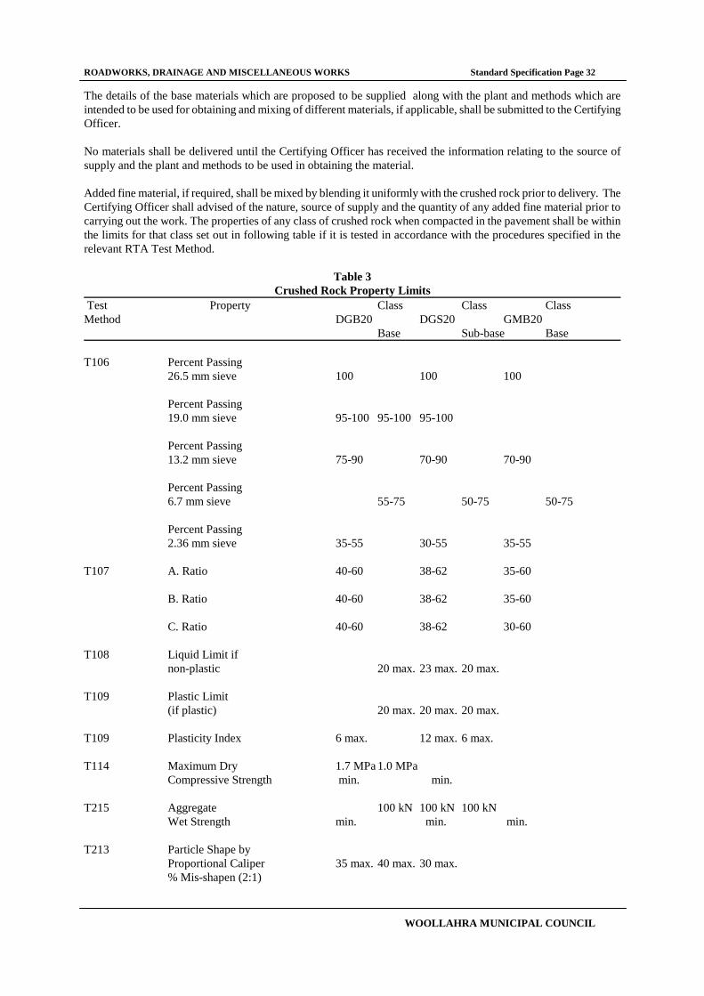
ROADWORKS, DRAINAGE AND MISCELLANEOUS WORKS Standard Specification Page 32
WOOLLAHRA MUNICIPAL COUNCIL
The details of the base materials which are proposed to be supplied along with the plant and methods which are
intended to be used for obtaining and mixing of different materials, if applicable, shall be submitted to the Certifying
Officer.
No materials shall be delivered until the Certifying Officer has received the information relating to the source of
supply and the plant and methods to be used in obtaining the material.
Added fine material, if required, shall be mixed by blending it uniformly with the crushed rock prior to delivery. The
Certifying Officer shall advised of the nature, source of supply and the quantity of any added fine material prior to
carrying out the work. The properties of any class of crushed rock when compacted in the pavement shall be within
the limits for that class set out in following table if it is tested in accordance with the procedures specified in the
relevant RTA Test Method.
Table 3
Crushed Rock Property Limits Test Property Class Class Class
Method DGB20 DGS20 GMB20
Base Sub-base Base
T106 Percent Passing
26.5 mm sieve 100 100 100
Percent Passing
19.0 mm sieve 95-100 95-100 95-100
Percent Passing
13.2 mm sieve 75-90 70-90 70-90
Percent Passing
6.7 mm sieve 55-75 50-75 50-75
Percent Passing
2.36 mm sieve 35-55 30-55 35-55
T107 A. Ratio 40-60 38-62 35-60
B. Ratio 40-60 38-62 35-60
C. Ratio 40-60 38-62 30-60
T108 Liquid Limit if
non-plastic 20 max. 23 max. 20 max.
T109 Plastic Limit
(if plastic) 20 max. 20 max. 20 max.
T109 Plasticity Index 6 max. 12 max. 6 max.
T114 Maximum Dry 1.7 MPa 1.0 MPa
Compressive Strength min. min.
T215 Aggregate 100 kN 100 kN 100 kN
Wet Strength min. min. min.
T213 Particle Shape by
Proportional Caliper 35 max. 40 max. 30 max.
% Mis-shapen (2:1)

ROADWORKS, DRAINAGE AND MISCELLANEOUS WORKS Standard Specification Page 33
WOOLLAHRA MUNICIPAL COUNCIL
T215 Percent Variation 35 max. 35 max. 35 max.
in Strength
(Dry/Wet)/Dry
The requirements stated in Table 3 are after any pre-treatment deemed necessary. Samples taken prior to compaction
in the pavement may require pre-treatment by procedures such as those described in the current relevant RTA Test
Methods prior to the commencement of the specified tests. The tests are based on the assumption that the density of
all fractions of the pavement material is approximately 2.65 g/ml. Materials containing fractions having a density
outside the range 2.50 to 2.85 g/ml will be individually investigated and assessed by the Certifying Officer.
The maximum value of the Liquid Limit may be increased to 23 for non-plastic crushed rock, provided that the value
determined is not influenced by the presence of adverse constituents.
After being subject to pre-treatment comprising two cycles of compaction , or to artificial weathering , the Plasticity
Index shall not exceed 6 for Class DGB material or 12 for Class DGS material, and it shall not increase by more than
3 from that of the sample prior to pre-treatment.
After soaking in water at 65 degrees Celsius for up to ten days the Plasticity Index shall not exceed 6 for Classes
DGB and GMB material or 12 for Classes DGS and GMS material, and it shall not have increased by more than 3
from that of an equivalent portion of the sample tested without the soaking.
The minimum Aggregate Wet Strength for crushed slag shall be 80 kN.
When tested in accordance with the current relevant RTA Test Method in a saturated but surface dry condition after
soaking in water for 24 hours, the 10 percent Fines Value of that portion of the sample passing the 19.0 millimetre
sieve and retained on the 9.5 millimetre sieve shall not vary by more than 35 percent from that of an equivalent
portion of the sample tested dry without soaking.
10.04 CRUSHED OR RIPPED SANDSTONE SUB-BASE COURSES
Crushed sandstone shall be obtained only from quarries or other sources which have been nominates to the Certifying
Officer and the Certifying Officer has granted permission in writing for the Quarry or other source to be used.
If required by the Certifying Officer, samples of material obtainable from a nominated Quarry or other source shall be
provided to the Certifying officer, together with certificates issued by a NATA registered laboratory, establishing that
the material complies with this Specification.
Sandstone shall be crushed or ripped from sound clean sandstone free of overburden, clay seams, shale or other
deleterious materials and shall conform to the following minimum requirements:
When tested to AS1289.C4.1-1997, linear shrinkage shall not exceed 5%;;
The CBR shall be not less than 30%;
Particle size grading shall be as shown in the following table:
NOMINAL SIZE (mm) PERCENTAGE PASSING (%)
75.00
85-100
53.00
75-100
37.50
65-100
26.50
57-94
19.00
50-88
9.50
37-76
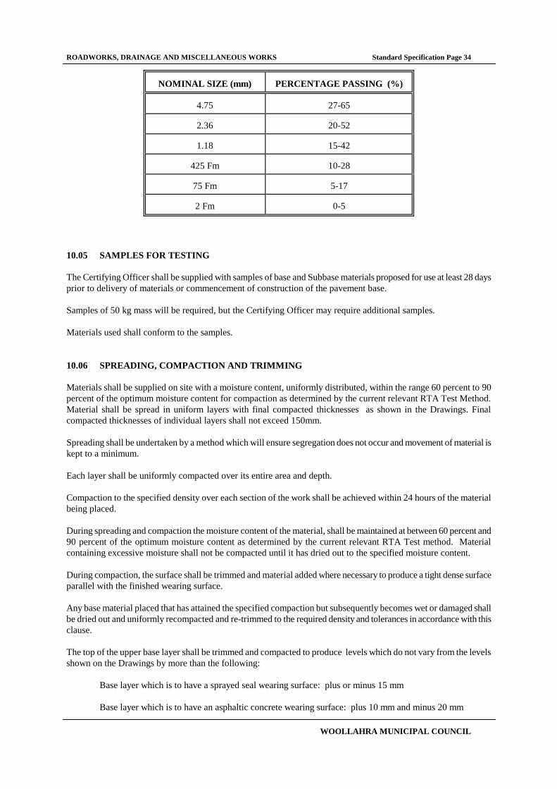
ROADWORKS, DRAINAGE AND MISCELLANEOUS WORKS Standard Specification Page 34
WOOLLAHRA MUNICIPAL COUNCIL
NOMINAL SIZE (mm)
PERCENTAGE PASSING (%)
4.75
27-65
2.36
20-52
1.18
15-42
425 Fm
10-28
75 Fm
5-17
2 Fm
0-5
10.05 SAMPLES FOR TESTING
The Certifying Officer shall be supplied with samples of base and Subbase materials proposed for use at least 28 days
prior to delivery of materials or commencement of construction of the pavement base.
Samples of 50 kg mass will be required, but the Certifying Officer may require additional samples.
Materials used shall conform to the samples.
10.06 SPREADING, COMPACTION AND TRIMMING
Materials shall be supplied on site with a moisture content, uniformly distributed, within the range 60 percent to 90
percent of the optimum moisture content for compaction as determined by the current relevant RTA Test Method.
Material shall be spread in uniform layers with final compacted thicknesses as shown in the Drawings. Final
compacted thicknesses of individual layers shall not exceed 150mm.
Spreading shall be undertaken by a method which will ensure segregation does not occur and movement of material is
kept to a minimum.
Each layer shall be uniformly compacted over its entire area and depth.
Compaction to the specified density over each section of the work shall be achieved within 24 hours of the material
being placed.
During spreading and compaction the moisture content of the material, shall be maintained at between 60 percent and
90 percent of the optimum moisture content as determined by the current relevant RTA Test method. Material
containing excessive moisture shall not be compacted until it has dried out to the specified moisture content.
During compaction, the surface shall be trimmed and material added where necessary to produce a tight dense surface
parallel with the finished wearing surface.
Any base material placed that has attained the specified compaction but subsequently becomes wet or damaged shall
be dried out and uniformly recompacted and re-trimmed to the required density and tolerances in accordance with this
clause.
The top of the upper base layer shall be trimmed and compacted to produce levels which do not vary from the levels
shown on the Drawings by more than the following:
Base layer which is to have a sprayed seal wearing surface: plus or minus 15 mm
Base layer which is to have an asphaltic concrete wearing surface: plus 10 mm and minus 20 mm
ROADWORKS, DRAINAGE AND MISCELLANEOUS WORKS Standard Specification Page 35
WOOLLAHRA MUNICIPAL COUNCIL
The top surface of the upper base layer shall also not deviate from the bottom of a 3 metre straight edge, laid in any
direction, by more than 7 millimetres in the case of a base layer which is to have a sprayed seal wearing surface and
by not more than 10 millimetres in the case of a base layer which is to have an asphaltic concrete wearing surface.
Any irregularities in excess of the tolerances stated above shall be corrected by loosening the surface, removing or
adding base material as required and re-trimming and re-compacting the area. In no case shall quarry dust or other
fine materials be used to build up depressions.
Immediately after the area has been trimmed and compacted the area shall be proof rolled. Proof rolling shall be
undertaken using a minimum 12 tonne static roller a loaded bogie axle tipping truck. The proof rolling shall be
carried out in the presence of the Certifying Officer or his delegate.
If, in the opinion of the Certifying Officer, the proof rolling reveals soft spots or other unsatisfactory areas these
areas shall be removed and replaced in accordance with the requirements of this Specification. The removal of the
subject areas may be waived if it can be demonstrated that the area in question complies with the requirements of the
Specification.
A primer seal may be applied over the base layer as protection provided that the primer seal is applied in accordance
with procedures outlined by the relevant RTA Form.
10.07 TRAFFIC LIMITATIONS ON BASES
Only vehicles and equipment essential for the construction of the base layer shall be permitted to travel over the
section of base under construction.
Only vehicles and equipment complying with the Load Limits of the current Local Government Act will be permitted
to travel over completed sections of the pavement base.
10.08 ASPHALTIC CONCRETE MIXES
After application of the tack coat asphaltic concrete shall be laid in two courses to make up the total compacted
thickness shown in the drawings. The base course and the surface course shall be as described in the Drawings.
Should it become necessary to apply a thin corrective surface course to achieve the specified tolerances on surface
finish, then such a course shall comprise dense grade asphaltic concrete with 5 millimetre nominal size aggregate of
the type appropriate for the section of pavement requiring correction.
10.09 PLACING ASPHALTIC CONCRETE
Tack coats and asphaltic concrete shall be delivered spread and compacted as described in the current relevant RTA
specification.
Bitumen shall be removed from and damage to kerbs or other work damaged or defaced during construction or paving
to road areas and hardstandings shall be made good.

ROADWORKS, DRAINAGE AND MISCELLANEOUS WORKS Standard Specification Page 36
WOOLLAHRA MUNICIPAL COUNCIL
11 PAVING BRICKS, COBBLESTONES, AND INTERLOCKERS
11.01 GENERAL
All surfaces and pavement structures executed under this part of the Specification shall be constructed true to the line,
levels, and grades, without local irregularities, as shown on the Drawings and in accordance with the relevant standard
drawings.
All pavement shall be finished to lines and levels that ensure positive drainage at all drainage outlets and channels.
11.02 EXCAVATION
Any existing concrete or asphalt footpath areas shall be excavated as per the EXCAVATION Section of this
Specification.
Any soft or damp patches shall be removed and replaced with suitable fill material and the whole area compacted in
accordance with the FOUNDATION section of the KERBS, GUTTERS, FOOTPATHS AND MEDIANS section of
this Specification.
11.03 BASE COURSE
The strength, constituents, quality, placement and acceptance of the base course material shall be in accordance with
the ROADWORKS AND HARDSTANDING sections of this Specification.
The top surface of the base course after compaction, shall not deviate from the bottom of a 2 metre straight edge, by
more than 10mm .
Where shown on the Drawings interlocking pavers shall have a reinforced concrete base. The base shall be
constructed in accordance with the CONCRETE WORKS section of this Specification and the relevant standard
Drawing.
Should the Certifying Officer deem it necessary the Base course shall be constructed of 5 MPa concrete in areas
where dust etc. from the base course may create a problem for adjacent public areas, such as shop entrances.
11.04 BEDDING SAND
Bedding sand shall be a well-graded sand passing a 4.75mm sieve and be suitable for concrete manufacture. The
sand shall be of uniform moisture content between 4-8% when spread, and shall be protected against rain when
stockpiled on site prior to spreading. Saturated sand shall not be used.
The bedding sand shall comply with the following grading limits:
Sieve Size(mm) % Passing
9.52 100
4.75 95 - 100
2.36 80 - 100
1.18 50 - 85
0.600 25 - 60
0.300 10 - 30
0.150 5 - 15
0.075 0 - 10
The bedding sand shall be free of soluble salts or other contaminants likely to cause efflorescence or lead to reduced
skid resistance.

ROADWORKS, DRAINAGE AND MISCELLANEOUS WORKS Standard Specification Page 37
WOOLLAHRA MUNICIPAL COUNCIL
The sand bedding shall be spread loose in a uniform layer, to a depth of approximately 35mm.
The sand bedding shall be screeded in a loose condition to a level such that, after compaction, the pavers shall be at
the correct levels and profiles.
The spread sand shall be carefully maintained in a loose condition and protected against pre-compaction both prior to
and following screeding. Any pre-compacted sand or screeded sand left overnight shall be loosened before further
paving units are placed. The sand bed shall not be screeded in advance of the laying face to an extent to which paving
will not be completed on that day.
Screeded sand must be fully protected against accidental pre-compaction, including compaction by rain or dew. Any
screeded sand which is pre-compacted prior to laying of units shall be removed and brought back to profile in a loose
condition.
11.05 CRUSHED AND RE-CYCLED CONCRETE
If crushed and re-cycled concrete is used as a base for pavers in lieu of the bedding sand described herein, it shall
comply with the description of Class B - Paver Base in the Section RE-CYCLED MATERIALS FOR FILLING AND
BASES in this Specification.
The material shall be placed and the bed for the pavers prepared as for Bedding Sand described above. Methods of
laying, compacting and filling the joints between the pavers shall be as applies to pavers laid on a natural sand base.
11.06 PAVING UNITS
Paving units shall comply with the current edition of the relevant Australian Standard or the CMAA Specification for
Concrete Segmental Paving Units (MA20).
The paving units shall be as specified on the Drawings or in other Documents.
A 1 sq.m. footpath paving sample shall be provided to the Certifying Officer prior to undertaking works. This sample
shall be used to determine the colour and texture variation of the paving block units that will be used . The sample
shall either be incorporated in the works or laid as a separate sample delivered to a site as directed by the Certifying
Officer. A separate sample shall be supplied for each different type of paving stone to be incorporated into the Works.
The Certifying Officer shall have 5 working days to make any comments he may have regarding the sample.
The Certifying Officer shall be notified of the completion of all the paving works. The Certifying Officer will then use
the 1 sq.m. sample provided to assess if the paving blocks used are within the colour and texture variation supplied in
the sample.
If the Certifying Officer determines the laid pavers are outside the colour and texture range provided in the sample,
the Certifying Officer will nominate which or all paving blocks are to be replaced.
The Certifying Officer shall be notified of any changes to the 1 sq.m. sample previously provided.
Interlocking paving blocks shall be as specified on the Drawings or in other Documents.
11.07 LAYING PATTERN
Footpath paving blocks are to be laid in a stretcher bond pattern, unless shown otherwise on the Drawings or in other
documents. The continuous joint shall run parallel to the kerb and gutter.
ROADWORKS, DRAINAGE AND MISCELLANEOUS WORKS Standard Specification Page 38
WOOLLAHRA MUNICIPAL COUNCIL
At the intersection of roadways, the paving pattern of the major roadway shall be continued from the alignment of the
adjacent building to the kerb and gutter of the intersecting road. This shall be completed in a manner shown on the
relevant standard Drawing.
Interlocking pavers shall be layed in a "Herringbone" laying pattern.
11.08 METHOD OF LAYING
Paving units shall be placed on the uncompacted screeded sand bed to the nominated laying pattern, with care being
taken to maintain the specified bond throughout the works. Paving units shall be placed such that all joints are
correctly aligned.
The first row shall abut an edge restraint and shall be laid at a suitable angle to the edge restraint to achieve the
required visual orientation of paving units in the completed pavement.
The size of the gaps between individual paving units and edge restraints, kerbs, etc, shall be 2mm " 1mm.
In each row all full units shall be aligned first. Closure units shall be cut and fitted subsequently. Closure units shall
be cut by power saw, or other appropriate method. The cut shall be clean and the paver must butt up against the
respective edge.
To fill spaces between 25 and 50mm wide, a coloured concrete (to match the paving block) shall be used, having a
1:2:4 cement, sand, course aggregate mix. The normal aggregate size shall not exceed one third the smallest
dimension of the infill space. For smaller spaces, dry packed mortar shall be used.
Except where it is necessary to correct any minor variations occurring in the laying bond, the paving units shall not be
hammered into position. Where adjustment of position is necessary, care shall be taken to avoid premature
compaction of the sand bedding.
Workmen shall use planks to avoid disturbing pavers prior to compaction if it is necessary to work over uncompacted
pavers. No other traffic shall be allowed on pavers prior to compaction.
11.09 SERVICE BOXES, AREA LIGHTS, POLES, ETC.
Traffic facilities such as parking and traffic signs, parking meters, and public facilities such as garbage bins, seats and
area lights shall have the block paving cut in around so that the block paving is of a tight fit where no sand or blocks
can be easily removed and it is safe for pedestrian usage.
All existing public utility services shall have a 50mm wide red-oxide concrete border around the utility. The red-
oxide concrete shall be at least 75mm thick.
All existing public utility service boxes shall be reset to suit any new levels. The respective utility authority shall be
liaised with for any adjustments to any public utility service boxes.
A 200 x 200mm wide strip shall be filled with coldmix adjacent to any Electricity pole.
11.10 TREE SITES
The paving units are to be continued in the stretcher bond pattern - leaving approximately 1 square metre free for
each tree site as per the relevant Standard Drawing.
A concrete edge restraint shall be formed on each side of the tree site.
On the kerbside, depending on placement of existing trees, an area the length of 1-2 pavers shall be paved.

ROADWORKS, DRAINAGE AND MISCELLANEOUS WORKS Standard Specification Page 39
WOOLLAHRA MUNICIPAL COUNCIL
Details of proposed "Tree Sites" shall be set out and confirmed with the Certifying Officer at least 7 days prior to the
pavers being laid in the respective areas.
11.11 JOINTS
Expansion joints 10mm in width shall be constructed at the interface of the paving blocks and concrete or asphalt
footpath pavements and/or any paving that may exist on private properties.
Expansion joints shall consist of a preformed joint filler in accordance with the current relevant RTA standards.
11.12 COMPACTION
The paving units shall be compacted to achieve consolidation of the sand bedding (approximately 10mm settlement),
and brought to design levels and profiles by not less than two passes of a high frequency, low amplitude mechanical
flat plate vibrator having a plate area sufficient to cover a minimum of 12 paving units.
Compaction shall proceed as closely as possible following laying and prior to the application of any traffic.
Compaction should not be attempted within one metre of the laying face. Compaction shall continue until lipping has
been eliminated between adjoining units.
All work to within one metre of the laying face must be left fully compacted at the completion of each days laying.
Any units which are structurally damaged during compaction shall be immediately removed and replaced.
11.13 FILLING JOINTS
After compaction of the paving blocks and prior to the termination of work on that day and prior to the application of
any construction traffic, sand for joint filling shall be spread over the pavement.
The joint filling sand shall be a well graded sand passing a 2.36mm sieve and be suitable for concrete manufacture.
The joint filling sand shall be as dry as practicable when spread.
The joint filling sand shall comply with the following grading limits:
Sieve Size (mm) % Passing
2.36 100
1.18 90 - 100
0.600 60 - 90
0.300 30 - 60
0.150 15 - 30
0.075 5 - 10
The joint filling sand shall be free of soluble salts or other contaminants likely to cause efflorescence or lead to
reduced skid resistance.
The filling sand shall be broomed to fill the joints and the pavement recompacted to achieve compaction of the joint
filling sand. As the work proceeds joints shall be checked for adequacy of filling and any shortfall shall be made
ROADWORKS, DRAINAGE AND MISCELLANEOUS WORKS Standard Specification Page 40
WOOLLAHRA MUNICIPAL COUNCIL
good prior to further compaction taking place. Any excess surface sand shall be removed promptly from the surface
of the paving blocks.
11.14 EDGE RESTRAINT
Adjacent to free edges where paving blocks do not adjoin a hard paved surface, a mass concrete edge restraint shall
be provided. The concrete shall be finished at a level 35mm above the base of the block and shall be a minimum
thickness of 100mm and depth of 200mm.
The adjacent ground shall be graded to meet the top of the paving.

ROADWORKS, DRAINAGE AND MISCELLANEOUS WORKS Standard Specification Page 41
WOOLLAHRA MUNICIPAL COUNCIL
12 STEELWORK
12.01 MATERIALS - GENERAL
If requested by the Certifying Officer , copies of mill test certificates shall be provided for all materials showing
chemical and mechanical properties. If mill test certificates are not available tests shall be carried out as directed by
the Certifying Officer in order to establish that the material is suitable for use in the Works.
Unless otherwise shown on the Drawings, materials shall be of the following grades:
Plates, Universal Beams & Columns, Sections Grade 250
Welded Beams & Columns Grade 300
Rectangular hollow sections Grade C350
Circular hollow sections Grade C350
12.02 SHOP DRAWINGS
Shop drawings shall be prepared from the Working Drawings in such detail as necessary for the complete fabrication,
assembly and erection of the structural steelwork to ensure correct fit-up and matching of steelwork to all other work.
Each shop drawing shall be clearly cross-referenced to the corresponding Working Drawing.
Shop drawings shall show all marking of members, material sizes, dimensions, holing and the location, type and size
of welds and bolts. Procedures for shop and site assembly, including the torque requirements and tightening method
for high-strength bolts, and requirements for surface preparation and protective coating shall be noted on the shop
drawings.
Minor modifications of details may be suggested to suit the particular shop and site procedures. Such modifications
shall be subject to the general agreement of the Certifying Officer before inclusion in the shop drawings.
The practicability of all design details shall be checked in regard to fabrication and erection and any amendments
considered necessary for the proper execution of the work shall be proposed. These proposed amendments shall be
subject to the agreement of the Certifying Officer.
12.03 DIMENSIONS
All work shall be fabricated to the actual dimensions required on site and all dimensions shall be verified on the site
prior to proceeding with the work.
12.04 FABRICATION
Fabrication shall be carried out to recognised standards of good practice and shall comply with the requirements of
the current edition of the relevant Australian Standard, except as otherwise specified.
On completion of fabrication, tolerances shall in accordance with the current edition of the relevant Australian
Standard unless otherwise specified or shown on the Drawings.
Cut edges shall be free of gouges, burrs and other defects that would adversely effect the serviceability of the
steelwork or detract from the finished appearance. All burrs, fins and raggedness left by sawing, punching, shearing,
cropping or flame cutting shall be removed before assembly.

ROADWORKS, DRAINAGE AND MISCELLANEOUS WORKS Standard Specification Page 42
WOOLLAHRA MUNICIPAL COUNCIL
Mechanically guided flame cutters may be used for stripping wide plates to required widths and for cutting a number
of similarly shaped pieces simultaneously.
Re-entrant corners shall be shaped notch-free to a radius of at least 11 mm.
12.05 BOLT HOLES
Holes for bolts shall generally not be more than 2 mm larger in diameter than the bolt. Holes for anchor bolts shall
not be more than 6 mm larger in diameter than the anchor bolt, unless otherwise shown on the Drawings.
The bolt pitch, and edge distances, shall conform with the requirements of the current edition of the relevant
Australian Standard.
The surface around holes shall be smooth and free of burrs, fins and other defects that may prevent solid seating of
contact surfaces.
Holes shall be drilled to size or punched 3 mm under size and reamed to size. Holes shall not be punched full size
without the prior agreement of the Certifying Officer. The region around holes punched full size shall be flat before
assembly. Dressing around such holes by appropriate means shall be permitted.
12.06 SPLICES AND JOINTS
Where available stock lengths of steel are shorter than the required length of member, splicing by complete
penetration full section butt welds may be permitted as directed by the Certifying Officer.
Welded splices in compound members shall be staggered, and the component plates and sections spliced before
compounding.
Critical field splices and joints shall be mated in the shop on completion of fabrication to ensure satisfactory fit when
erected.
Should field splices and joints, whether bolted or welded, in addition to those shown on the Working Drawings be
proposed or required, or in different locations, such connections shall be by agreement with the Certifying Officer in
respect to design, procedure and workmanship.
12.07 WELDING
12.07.01 General
All welding shall be carried out by electric metal-arc processes in accordance with the current edition of the
relevant Australian Standard.
Welding plant and equipment shall be of a standard acceptable to the Superintendent and shall be operated
in accordance with the manufacturer's instructions.
Electrodes and other welding consumables shall be stored and used as recommended by the manufacturer.
Covered electrodes for manual arc welding and fluxes for automatic and semi-automatic welding that have
been wet or dampened shall not be used whether they have been re-dried or not.
When welding heavy sections and in other special applications and conditions, low hydrogen electrodes may
be used subject to the conditions of the current edition of the relevant Australian Standard. Low hydrogen
electrodes shall be employed if so directed by the Certifying Officer.
12.07.02 Welding Details

ROADWORKS, DRAINAGE AND MISCELLANEOUS WORKS Standard Specification Page 43
WOOLLAHRA MUNICIPAL COUNCIL
All welding shall comply with details shown on working drawings or, if no details are shown, as directed by
the Certifying Officer.
12.07.03 Welding Personnel
All welding shall be carried out under the supervision of a person who holds a welding supervisors
certificate in structural welding in accordance with the current edition of the relevant Australian Standard, or
other qualifications acceptable to the Certifying Officer.
The qualifications of welders shall comply with the current edition of the relevant Australian Standard .
Evidence acceptable to the Certifying Officer that welders are qualified for the procedures they will be
carrying out shall be provided. The Certifying Officer may elect to observe qualification and procedure tests.
12.07.04 Welding Procedures
Details of welding procedures shall be provided to the Certifying Officer as part of the shop drawings and
such procedure tests as the Certifying Officer may require in accordance with the current edition of the
relevant Australian Standard shall be carried out prior to their employment in the work.
Preparation of edges to be welded shall be carried out by mechanical means or machine flame cutting.
Manual flame cutting shall only be used if permitted by the Certifying Officer and provided that the cut
surfaces are ground to the satisfaction of the Certifying Officer.
The procedure and sequence of welding shall be such that distortion and restraint are minimised. When, in
the opinion of the Certifying Officer, welding is likely to result in excessive shrinkage stresses or distortion,
a complete programme for the welding sequences to be used shall be prepared. When excessive distortion is
evident, it shall be corrected to the satisfaction of the Certifying Officer.
When site welding is to be employed, the assembly of steelwork shall be planned in sections to permit a
maximum amount of welding to be completed on the ground. The work shall be planned in a manner to
limit overhead welding as much as possible.
Areas to be site welded shall be left uncoated for a distance of at least 50 mm from the weld line unless the
coating is a "weld through" type primer.
No welding or flame cutting shall be carried out while a member is in a state of stress without the prior
permission of the Certifying Officer.
12.08 BOLTED JOINTS
12.08.01 Washers
At least one washer shall be placed under the bolt head or nut, whichever is to be rotated when tightening.
Taper washers shall be used where the surface under the bolt head or nut is not perpendicular to the axis of
the bolt.
12.08.02 Mild Steel Bolts
Unless otherwise noted on the Drawings, commercial grade mild steel bolts shall be used only for anchor
bolts and purlin and girt connections.
ROADWORKS, DRAINAGE AND MISCELLANEOUS WORKS Standard Specification Page 44
WOOLLAHRA MUNICIPAL COUNCIL
Mild steel bolts, washers and nuts shall comply with the current edition of the relevant Australian Standard.
12.08.03 High Strength Bolts
High strength bolts, nuts and washers and bolting procedures shall comply with the current edition of the
relevant Australian Standard. Where hot-dip galvanised bolts are required, the nuts shall be provided with
supplementary lubrication as specified in the current edition of the relevant Australian Standard.
12.08.04 Protective Treatment
The protective treatment to be applied to bolts shall be as shown on the Drawings.
Contact surfaces of friction-type bolted joints may be primed with inorganic zinc silicate coating prior to
installation of the bolts but shall be free of any other type of paint.
12.09 DELIVERY AND STORAGE
12.09.01 Identification
Before dispatch to site each separate member shall be distinctly marked in accordance with the marking
diagram of the shop drawings. The mark numbers may be painted but shall also be stamped on the member
in characters at least 13 mm high. The members shall also carry orientation marks required for assembly
and erection.
All bolts, nuts, washers and other small items shall be properly labelled for easy identification and each
shipment of steel shall contain the bolts, nuts and washers required for the erection of that shipment.
Where practicable, loose pieces for connections shall be securely attached to the members at or adjacent to
the point of connection.
12.09.02 Handling and Storage
Steelwork shall be handled, transported and stored in a manner that will not cause permanent deformation
nor result in excessive damage to the protective coating. Members damaged during handling and storing
shall be liable to rejection.
Repairs to damaged steel and coating shall be carried out to the satisfaction of the Certifying Officer.
Steelwork delivered to the site shall be stored clear of the ground and separated from other steelwork items
until erected.
Bolts, nuts, washers and other small pieces shall be kept in grit free containers and stored in weather-proof
premises.
12.10 ERECTION
12.10.01 General
An erection procedure shall be adopted such that all members can be placed and fixed in position without
distortion.

ROADWORKS, DRAINAGE AND MISCELLANEOUS WORKS Standard Specification Page 45
WOOLLAHRA MUNICIPAL COUNCIL
During erection steel members shall not be cut, welded or drilled without the prior agreement of the
Certifying Officer. Drifting shall only be used for bringing parts into position but not to match unfair holes
nor to enlarge holes or otherwise distort metal.
Bracing, guying and other temporary members to facilitate erection shall be provided and shall be affixed in
a manner that does not deform or deface permanent steelwork.
Upon completion of erection all temporary bracing, erection bolts and the like shall be removed and the
permanent steelwork made good to the satisfaction of the Certifying Officer.
Tolerances for setting out and erection of steelwork shall be in accordance with the current edition of the
relevant Australian Standard.
No final tightening of bolts or permanent welding shall be carried out until sufficient members have been
erected to enable the work to be aligned, levelled and plumbed as specified.
12.10.02 High Strength Bolted Joints
High strength bolts shall be installed in accordance with the current edition of the relevant Australian
Standard. Bolts shall be tightened by the part-turn method. Bolts and nuts shall be location marked to check
that the correct rotation from the snug tight position has been obtained.
Facilities shall be provided so that all joints can be inspected by the Certifying Officer both before and after
tightening of the bolts.
As bolts are finally tightened they shall be marked with paint or other indelible marker to ensure that the
work is systematically carried out and to facilitate inspection by the Certifying Officer.
12.11 ATTACHMENT TO CONCRETE FOUNDATIONS
Steelwork supported by concrete or masonry shall be bedded on cement grout. Unless otherwise specified, the grout
shall consist of a Portland cement/sand mortar having a minimum compressive strength of 25 MPa at 28 days.
The steelwork shall be set up on steel packing or on levelling nuts on the anchor bolts. Grouting shall not be
commenced until sufficient steelwork has been aligned, levelled and plumbed, adequately braced and secured by
permanent fastenings. Grouting shall not commence until permitted by the Certifying Officer.
Immediately before grouting, the space under the steel shall be thoroughly cleaned and wetted and left free of excess
moisture.
Grout shall be placed by either of the following two alternatives:
A The grout shall be mixed as dry as possible and shall be worked under the steel by thoroughly ramming with
a blunt tool; or
B Suitable fluid grout shall be pumped under pressure. Holes shall be provided in the steelwork as required
for grout injection and air bleed-off.
Side forms shall be provided to retain grout. The space to be grouted shall be completely filled with mortar. Exposed
grout edges shall be splayed and neatly finished. The edges shall be cured for at least three days by covering with
sand, kept continually moist or by use of an approved curing compound.
When non-shrink grout is specified, the work shall be performed using an appropriate pre-mixed grout. Details of the
proposed grout shall be submitted to the Certifying Officer prior to carrying out the work. Preparation of surfaces,
mix proportions, application procedures and curing shall be in strict accordance with the manufacturer's instructions.

ROADWORKS, DRAINAGE AND MISCELLANEOUS WORKS Standard Specification Page 46
WOOLLAHRA MUNICIPAL COUNCIL
13 PROTECTIVE COATING FOR STEELWORK
13.01 GENERAL
Protective coating shall be carried out in accordance with the principles of the current edition of the relevant
Australian standard. Coating materials, surface preparation and methods of application shall, except where
specifically varied by this Specification, be in accordance with the current edition of the relevant Australian standards
and in accordance with the coating manufacturer's recommendations.
To ensure compatibility of the layers of a coating system, the coating material used in all layers shall be provided by
the same manufacturer.
Before commencing preparation for coating, the name of the protective coating applicator and full details of the
coating systems proposed to be used on the several parts of the works, shall be submitted to the Certifying Officer,
including manufacturer's descriptions and recommendations for surface preparation and for application.
13.02 PREPARATION AND APPLICATION CONDITIONS
All preparation for, and application of coatings (except hot dip galvanising) shall be carried out in dry conditions with
a steel temperature not less than 3EC above the dew point.
Surfaces prepared for coating shall be cleaned of dust and coated as soon as practicable.
The application of paint to blast cleaned surfaces shall be commenced within four hours of completion of blast
cleaning and shall be completed on that day and before dew point is reached.
Under no circumstances shall paint or primer be applied over moisture on the surface of the metal. Should rain fall
during or after cleaning, but before the application of paint or primer, the whole of the surface in question shall be re-
cleaned. The Certifying Officer may prohibit the continuation of painting if, in his opinion, rain is likely to fall within
two hours of painting. Paint shall not be applied during damp or foggy conditions.
Effective controls shall be established to preclude operations in unsuitable weather conditions. Work shall not be
performed on surfaces wetted or likely to become wetted after blasting and before coating, when the relative humidity
exceeds 90%, or when the metal surface temperature exceeds 50EC or is lower than 10EC.
All coating operations shall be performed in a neat and workmanlike manner by personnel with proven experience in
the field. Each coating shall be uniform, free from runs and sags, and shall be allowed to dry and/or cure in
accordance with the manufacturer's instructions.
Such measures as are necessary shall be taken to obviate health hazards arising from the use of paints and coating
materials and to satisfy all requirements within the trade. Such equipment and measures as are necessary for the
adequate protection of adjacent structures, permanent plant and equipment against damage or disfigurement during
both cleaning and coating operations shall be taken. At the completion of the work, all paint spots, stains, etc. shall
be removed so as to leave the site and all adjacent structures in a clean condition acceptable to the Certifying Officer.
Where the installation of plant, flooring and/or similar items will prevent surfaces from being satisfactorily coated
after erection, the surfaces that will be inaccessible shall be finish coated prior to erection, or while still accessible for
purposes of coating.
13.03 PROTECTION AND REPAIRS
Coated steelwork shall be protected during transport, storage and erection to prevent damage to the coating.
Protection should include, but not be limited to, use of cloth slings, padding and blocking during transport and
storage, and storage clear of the ground and of adjacent stored members.

ROADWORKS, DRAINAGE AND MISCELLANEOUS WORKS Standard Specification Page 47
WOOLLAHRA MUNICIPAL COUNCIL
All damaged areas of coating shall be made good to the satisfaction of the Certifying Officer. All areas to be repaired
shall be thoroughly degreased. Generally, repairs shall include surface preparation, priming and top coating as
required for the original coating. Damaged areas of zinc primed coating systems, shall be cleaned back to bright
metal and spot-primed immediately with organic zinc rich primer, dry film thickness 100 Microns. Damaged areas of
hot dip galvanised steel shall be reinstated by lightly spot-blasting (or sanding with abrasive discs) the damaged areas,
and spot-primed with organic zinc rich primer to achieve a dry film thickness of 0.1 mm. Where the coating system
includes top coats, these shall then be applied or reinstated over the patch primed area.
13.04 SURFACE PREPARATION
Preparation for hot dip galvanising shall consist of removal of paint, oil, grease, welding slag and spatter, followed by
pickling to remove mill scale and rust. Pickling shall be carried out in the galvanising workshop. Preparation for
other coatings shall consist of power tool cleaning or abrasive blast cleaning, depending on the type of coating to be
used or as shown on the Drawings.
All areas of the surfaces which are to be blast cleaned and which show any trace of oil or grease shall be degreased
using an appropriate cleaning agent prior to blasting to avoid recycling of these contaminants during the blast
cleaning operations.
Abrasive blast cleaning shall be carried out by sand or grit blasting using compressed air nozzles. Metallic abrasive,
if used, shall be sharp and hard and free from dust. Acceptable materials will be cast iron grit, or cut wire. Sand
abrasive, if used, shall be substantially free from dust and clay and completely free of salt.
The specified blast cleaning standard shall be deemed to be the absolute minimum requirement for a particular item
and coating specification. All surfaces to be coated shall be dry abrasive blast cleaned and wet blasting will not be
permitted. Surface profile height after blasting shall be within the range 0.025 to 0.040 mm.
All abrasive blast cleaned surfaces shall be kept free from contamination and to this end, operators should be
equipped with gloves. Areas inadvertently contaminated with bare hands shall be re-cleaned as specified or carefully
wiped with an appropriate solvent.
Where a surface shows discolouration within a short time after blast cleaning, the surface shall be thoroughly washed
with fresh water, dried and re-blasted. If necessary, the procedure shall be repeated.
13.05 APPLICATION OF COATINGS
Unless otherwise specified, all primers and subsequent coats used throughout the Works shall be applied according to
the manufacturer's recommendations, and to the satisfaction of the Certifying Officer.
Mixing, thinning and application instructions as nominated by the coating manufacturer shall be absolutely adhered to
and no other addition to the mixed coating shall be used.
Immediately after blasting operations and before the commencement of coating, all surfaces shall be air blown with
clean dry air or efficiently brushed down with fibre bristles giving particular attention to corners, intersections and
horizontal areas where settlement of dust would be most likely to occur.
Unless specified, all prime coats shall be applied in the applicator's own workshop.
Where spraying of zinc based and similar high solids type paints is to be carried out, the pressure pot shall be fitted
with an efficient agitator which shall be in constant use during the application of the coating.
An efficient air line filter shall be fitted as close as possible to the pressure pot to eliminate line condensation and oil
in air supply to the spray gun. All equipment, including receptacles, shall be to the Certifying Officer's satisfaction.
All unpainted machined steel surfaces of sliding bearing plates, rockers or rollers shall be given two coats of an
appropriate inhibitive grease to prevent corrosion.

ROADWORKS, DRAINAGE AND MISCELLANEOUS WORKS Standard Specification Page 48
WOOLLAHRA MUNICIPAL COUNCIL
13.06 HOT DIP GALVANISING
Detailing of all hardware to be galvanised shall conform to the procedures set out in the current edition of the relevant
Australian Standard. All units to be galvanised shall be fabricated in sections suitable for the galvanising baths and
galvanised after fabrication. Where modifications, drain holes, etc. are required for galvanising, they shall be detailed
on the shop drawings.
All steelwork and metalwork specified to be galvanised shall be hot dip galvanised to comply with the current edition
of the relevant Australian Standard to provide a minimum of 600 g/m2 zinc coating.
Care must be taken to ensure that the threads of nuts and/or bolts are protected to eliminate the necessity for re-
cutting.
Where galvanised surfaces are affected by welding, the surfaces shall be thoroughly cleaned and zinc-sprayed to a
minimum thickness of 0.1 mm.
Where practicable, all galvanising is to be carried out after fabrication.
Galvanised surfaces shall be free from uncoated spots. The zinc coating shall be free from blisters, flux, black spots,
dross and projections which will interfere with the proper use of the article and from other defects not consistent with
good galvanising practice.
13.07 CHROME PLATING
Where chromium (chrome) plating is specified it shall be in accordance with the current edition of the relevant
Australian Standard.
Steelwork is to be heavily coppered, nickel-plated to a depth of at least 0.050 mm and overlaid with chromium plating
to a depth of 0.012 mm then buff-polished to a lustrous finish.
Copper and brass are to be nickel-plated and then chromium plated as specified for Steelwork.
13.08 PRIMING
Unless other finishes are specified, or the member is to be encased in concrete, all steelwork shall be shop-primed
before delivery to site.
All surfaces to be shop-primed shall be thoroughly cleaned. Rust mill scale and welding slag shall be removed and
the surface thoroughly dried.
Immediately after cleaning and drying, the surfaces shall be completely covered by a coat of anticorrosive red oxide
zinc phosphate primer suitable for application on metal surfaces. The primer may be applied by brushing and/or
dipping.
13.09 SURFACES NOT TO BE COATED
The following surfaces and materials shall not be blasted or coated unless specified, indicated on the drawings or
otherwise directed by the Certifying Officer:
! areas to be field welded shall be masked after blasting to leave a 50 mm unprimed margin. A further 50 mm
of primer shall be masked before top coating to facilitate final touch-up of field welds

ROADWORKS, DRAINAGE AND MISCELLANEOUS WORKS Standard Specification Page 49
WOOLLAHRA MUNICIPAL COUNCIL
! mating surfaces of friction grip connections shall not be coated except where galvanising or an inorganic
zinc silicate prime coat is required
! metalwork to be embedded in concrete shall be cleaned of grease, paint and loose rust before embedment,
and shall not be coated unless required to be galvanised, except that surface preparation and priming shall
extend to a line not less than 50 mm below the surface of the concrete.
13.10 CONNECTIONS
Generally, completed welded or bolted connections shall be degreased, prepared, primed and top coated, where
applicable, with the coating system required for the steelwork. Where galvanising or inorganic zinc silicate primer is
used, only hot dip galvanised bolts, nuts and washers shall be used in bolted joints. Welded joints in galvanised or
inorganic zinc silicate primed steelwork shall be blast cleaned Class 2 1/2 and reprimed with organic zinc rich primer.
If top coating is required, the galvanised surfaces of joints shall be degreased as necessary and etch primed before
top coating.
Bolted connections in galvanised or inorganic zinc silicate primed steelwork shall be prepared and coated as specified
for repairs.
13.11 INSPECTION
Work may be inspected by the Certifying Officer or his nominated inspector at each stage of the coating operation, ie
after blasting, prior to each coat and after final topcoat application. Where so specified, by the Certifying Officer,
application of coatings shall not proceed until each previous operation has been inspected by the Certifying Officer or
his nominated inspector.
A list of work and procedures shall be submitted to the Certifying Officer prior to any coatings being applied. All
coats are to be applied in strict accordance with the manufacturer's recommendations and as set out in the coating
specification.
The coating manufacturer's technical representative shall be available for consultation and to inspect work, both on-
site and in the applicator's workshop, in conjunction with the Certifying Officer or his nominated inspector. The
procedure associated with surface preparation and the application of each coating shall in the first instance be carried
out in the presence of the Applicator, the Technical Representative of the coating manufacturer and the Certifying
Officer or his nominated inspector.
Inspection will be carried out in accordance with the recommendations of the current edition of the relevant
Australian Standard.
For the purpose of inspection, the Certifying Officer shall be given five (5) days written notice of the intention to
apply the paint coats to the steelwork. The Certifying Officer shall be given all assistance required during the
inspection to permit examination.
Wet paint and dry film thickness gauges shall be provided and operated to ensure the correct thickness of each coat
and of the full paint system.
The dry paint film thickness gauge shall be suitably calibrated and regularly checked against a known standard to
ensure its accuracy.
Surface profile, coating thicknesses and coating adhesion will be checked by the Certifying Officer or his nominated
inspector using the following methods:
! surface profile will be measured by visual examination and comparison with profile standards or by use of a
Surface Profile Gauge

ROADWORKS, DRAINAGE AND MISCELLANEOUS WORKS Standard Specification Page 50
WOOLLAHRA MUNICIPAL COUNCIL
! wet film coating thicknesses, dry film coating thicknesses and adhesion shall be measured in accordance
with the current edition of the relevant Australian Standard.
If these film thicknesses, adhesion, profile and the like are not in accordance with the Specification or the coating
manufacturer's published data, the surfaces concerned shall be cleaned back to bright metal and recoated.
13.12 COATING MATERIALS
Materials used in protective coatings shall be in accordance with the following:
! inorganic zinc silicate coating shall consist of zinc powder in a self-curing inorganic medium. Materials
shall comply with the requirements of the current edition of the relevant Australian Standard.
! organic zinc rich primer shall consists of powdered zinc in an epoxy base and curing agent, and shall comply
with the requirements of the current edition of the relevant Australian Standard.
! etch primers for galvanised items shall consist of zinc tetroxy-chromate pigment in a polyvinyl butyl resin
binder and a catalyst component containing phosphoric acid, with a volatile solvent vehicle
! high-build vinyl coating shall consist of vinyl resin binder and volatile solvent with pigment to suit
! micaceous iron oxide coating shall consist of micaceous iron oxide pigment with or without aluminium or
red iron oxide pigment to distinguish between coats, carried in an alkyd resin binder complying with the
current edition of the relevant Australian Standard.
Unless otherwise specified hot dipped galvanised surfaces shall not receive further protective coating except in cases
where the galvanising has been damaged, in which case they shall be repaired as directed by the Certifying Officer.

ROADWORKS, DRAINAGE AND MISCELLANEOUS WORKS Standard Specification Page 51
WOOLLAHRA MUNICIPAL COUNCIL
14 BRICKWORK AND BLOCKWORK
14.01 BRICKS
Bricks shall conform to the current edition of the relevant Australian Standard. They shall be sound, hard and well
burnt, of uniform shape and size with unbroken arrises, nominal size 230 x 110 x 76 m. Clinkers or callows shall not
be used.
Sample bricks representing those intended for use in the work shall be submitted to the Certifying Officer prior to
ordering the bricks. Samples which meet the requirements of the Specification and Drawings shall be retained on site
in good condition. Only bricks equal to the retained samples shall be used in the works.
Dumping of bricks is prohibited.
14.02 CONCRETE MASONRY BLOCKS
Concrete blocks shall be 400 mm long x 200 mm high x 100mm thick, hollow concrete masonry conforming to the
requirements of the current edition of the relevant Australian Standard. Half blocks and smaller blocks shall be used
as required for particular dimensions. Where it is unavoidable that blocks be cut, they shall be cut with an abrasive
saw to give a neat finish.
14.03 STRUCTURAL BLOCK WORK
Structural walls and other work shown in the Drawings as manufactured from concrete filled and reinforced "hollow
concrete blocks" or other form of masonry shall be constructed to details shown in the Drawings.
Concrete used to grout the cavities in the blocks shall have 10mm maximum sized aggregate and cement and water
content designed to provide F'c 35 MPa unless shown otherwise in the Drawings. An appropriate plasticising agent
may be used to delay initial set and facilitate the consolidation of the concrete in horizontal and vertical cavities. If a
plasticising agent is proposed details shall be submitted to the Certifying Officer at least 5 (five) working days before
it's intended use.
Joints between blocks shall be sufficiently mortared or sealed to prevent loss of grout. In the case of curved walls laid
dry, blocks shall be profiled so that the perpends meet neatly on both faces to prevent grout loss.
If necessary to prevent stains or disfiguring from minor grout or water loss at faces which are exposed when the wall
is completed, joints shall be sealed from inside the cavities.
Grouting shall be carried out as the blocks are laid and grout shall be well consolidated into all cavities. Pencil
vibrators and/or hand rodding shall be used if necessary to achieve a dense grout matrix in difficult areas and/or
cavities which are reinforced.
Generally, not more than two courses shall be laid without grouting. In cases where it is demonstrated that more than
two courses can be grouted satisfactorily, the Certifying Officer may permit more than two courses to be laid prior to
grouting.

ROADWORKS, DRAINAGE AND MISCELLANEOUS WORKS Standard Specification Page 52
WOOLLAHRA MUNICIPAL COUNCIL
15 STORMWATER DRAINAGE
15.01 MATERIALS
15.01.01 Pipes
Reinforced concrete, Vitrified clay and/or Polyethylene pipes shall comply with the requirements of the
current edition of the relevant Australian Standard. Pipes shall be of the class shown on the drawings.
Rubber joint rings for use with reinforced concrete or vitrified clay pipes shall comply with the requirements
of the current edition of the relevant Australian Standard.
15.01.02 Precast Reinforced Concrete Box Culverts
Precast reinforced concrete box culverts shall comply with the requirements of the current edition of the
relevant Australian Standard.
15.01.03 Selected Backfill
Selected backfill shall comply with the requirements of the FILLING section of this Specification.
15.01.04 Concrete
Concrete, reinforcement and formwork for drainage structures shall comply with the requirements of the
CONCRETE section of this Specification. Concrete strength shall be as specified on the Drawings.
15.01.05 Cement Mortar
Cement mortar shall comply with the requirements of the current edition of the relevant Australian Standard.
15.02 PRECAST CONCRETE BOX DRAINS
Precast concrete box drains shall be in accordance with the current edition of the relevant Australian Standard and/or
RTA Standard Form.
The base of Precast Concrete Box Drains shall be cast in-situ Reinforced concrete to the line, level and grade as
shown on the Drawings.
The box section shall be positioned true to line, the invert level of the section true to level and grade as shown on the
Drawings and the sections closely butted together. A thin layer of mortar, one (1) part cement to three (3) parts sand,
shall be used on the sections prior to placing the sections together.
The maximum permissible tolerance shall not exceed 10mm above or below true grade nor 20mm to either side of the
true alignment, for any two points 8m apart. Moreover, no portion of the work shall depart more than 10mm from
true level, as determined from the nearest convenient bench mark which shall be indicated by the Certifying Officer.
Any culvert or culverts not laid within these tolerances shall be lifted and relaid so that the gradient and alignment are
within the specified tolerances.
In all cases care shall be taken with laying so that the interior of the box sections have a neat, smooth and uniform
surface at the joints and the interior surfaces of the sections shall be cleaned of any excess mortar after jointing. The
joints shall be protected from rapid drying by covering with wet bags for at least three (3) days after placing or
alternatively by the application of an approved curing compound.

ROADWORKS, DRAINAGE AND MISCELLANEOUS WORKS Standard Specification Page 53
WOOLLAHRA MUNICIPAL COUNCIL
Trenches at the sides of box drains shall be carefully packed and solidly compacted at the sides with sand or metal
dust in uniform layers which shall be carried up to the top of the precast section all to the satisfaction of the Certifying
Officer.
15.03 REINFORCED CONCRETE PIPE DRAINS
15.03.01 Description of Pipe
The class and size of pipes shall be as shown in the Drawings. Unless shown otherwise, all pipes shall be
manufactured for rubber ring jointing and shall be supplied complete with rings suited to the pipe
manufacturer's details.
The size, class, manufacturer's name and date of manufacture shall be indelibly marked on the obvert of
every pipe. The markings shall be large, durable and distinctive enough to be read easily during CCTV
scanning some years after the pipe has been put into service.
15.03.02 Pipe Bedding
The material used for bedding of pipes shall be approved granular material having a high permeability and a
high stability when saturated; and be free of organic matter and coarse material retained on a 2.36mm sieve.
Samples of the types of materials intended to be used shall be submitted to the Certifying Officer prior to
their use.
No bedding material shall be placed until the excavation has been inspected by the Certifying Officer. After
inspection by the Certifying Officer bedding material shall be placed and compacted so that the bottom of
the trench is at the correct level for pipe laying.
15.03.03 Method of Laying
Before pipes are laid all dirt and foreign material that may have entered the pipe shall be removed and the
outside of spigots and inside of sockets thoroughly cleaned of foreign matter.
The pipes shall be laid and jointed accurately to lines, gradients and levels shown on the plans. All pipes
shall be laid in such a manner that pipe barrels have solid bearing throughout their length.
The maximum permissible tolerance in any single length of pipe shall not exceed 10mm above or below true
grade, nor 10mm to either side of the true alignment and the maximum departure from the grade shall not
exceed 20mm between any two points 8 metres apart. No portion of the work shall depart more than 10mm
from true level.
Any pipe or pipes not laid within these tolerances shall be lifted and relaid so that the gradient and alignment
are within the tolerance specified.
Laying shall commence at the low points of the pipeline and proceed uphill.
The space between abutting ends of pipes shall not exceed one-half (1/2) per cent of the diameter of the
pipe. Where bandage joints or spigot and socket pipes are used, small recesses 150mm long shall be left
under pipe joints to permit jointing, or in the case of spigot and socket pipes to allow the barrels to bear
evenly on the foundation for their full length.
Where two or more lines of pipe are to be laid side by side, the space between the lines of pipe shall be not
less than 300mm unless otherwise specified or shown on the Drawings.
ROADWORKS, DRAINAGE AND MISCELLANEOUS WORKS Standard Specification Page 54
WOOLLAHRA MUNICIPAL COUNCIL
All open ends of pipeline stubs shall be baulked and closed off before backfilling commences.
If required by the Certifying Officer everything necessary shall be provided to demonstrate that no
obstructions or defects exist in the pipeline after backfilling. Any obstruction or other defect shall be
removed to the satisfaction of the Certifying Officer.
15.03.04 Method of Jointing
Rubber ring joints for concrete pipes shall be formed by placing the rubber ring evenly over the spigot end
of the pipe and rolling it into the socket, care being taken to ensure that the joint is free from dirt or other
obstructions and that the rubber ring is placed evenly in the joint. Rubber ring joints shall be fitted in the
manner described by the manufacturer.
Where precast collars or spigot and socket pipes are used, joints may be made with cement mortar or an
appropriate bituminous filler. Where possible, the joint immediately adjacent to a pit and/or a headwall
shall not be made until after the pit or headwall is constructed.
In all cases care shall be taken that the interior of pipes are cleaned of any excess jointing material after
jointing. Mortar joints shall be protected from the sun, and if necessary covered with earth or wet bags to
prevent rapid drying of the mortar for at least three (3) days after placing or alternatively by the application
of an appropriate curing compound.
All holes provided in concrete pipes for lifting or handling purposes shall be plugged with concrete bungs
supplied by the manufacturer and are to be rammed home. The Certifying Officer may require the
installation of bungs using a bitumen paint. All holes shall be plugged to the satisfaction of the Certifying
Officer prior to the backfilling of trenches.
15.03.05 Methods of Testing
Copies of the following shall be submitted to the Certifying Officer.
(i) Video tapes of Close circuit television video inspection carried out on all pipeline works after the
lines have been backfilled and the backfill completely compacted and after any overlying
earthworks and/or roadworks have been completed
In the event of joints or pipes bring damaged during backfilling or other subsequent work, the
damaged pipes shall be removed and replaced.
(ii) Works as executed levels on the invert of the constructed pits and on the inverts of any inlet or
outlet pipes.
15.04 DRAINAGE STRUCTURES
Drainage Structures such as gully pits, junction chambers etc. shall be constructed in the locations and of the type as
shown on the Drawings.
Lintels shall be laid with the top of the lintel flush with the top of the adjacent Kerb. A transition of at least 2 metres
long between the Kerb and Gutter and either end of the lintel shall be installed after the Lintel has been installed.
For junction chambers set in roadways, footpaths, medians or grass verges the covers shall finish flush with the
surrounding surface. For junction chambers set in embankments the cover shall be laid horizontally and the
surrounding ground shaped to suit the position of the cover.

ROADWORKS, DRAINAGE AND MISCELLANEOUS WORKS Standard Specification Page 55
WOOLLAHRA MUNICIPAL COUNCIL
16 SUBSOIL DRAINS
16.01 PIPES
Pipes for subsoil drains shall be 100mm diameter "socked" corrugated black high-density polyethylene unless noted
otherwise in the Documents. Unless otherwise specified, pipes shall be 100mm diameter.
16.02 FILTER MATERIAL
Filter material shall be coarse sand or crushed stone complying with one of the gradings in the following Table.
Where subsoil drains are laid in or adjacent to areas to be planted the pH of the filter material shall be in the range 6-
7.
TABLE 4
AS Sieve
Percentage Passing by Mass
Size (mm)
Fine Filter
Coarse Filter
Combined Filter
26.5
100
100
19.0
90-100
95-100
9.5
100
65-85
80-95
4.25
90-100
-
65-80
2.36
70-90
-
45-65
1.18
-
15-30
25-45
0.60
-
0- 2
12-20
0.30
7-16
3- 8
0.15
0- 4
0- 2
0.075
0- 2
16.03 TRENCHES
The standard width of trench shall be 300mm. Where invert levels are not specified the minimum depth to pipe invert
shall be 1m.
Unless otherwise detailed or directed, trenches for longitudinal drains shall be located so that the pipe centre line will
be 150mm from edge of pavement or behind back of kerb as the case may be.
16.04 BEDDING, LAYING AND JOINTING
Unless otherwise detailed or permitted, the minimum grade of pipes shall be 1%. Corrugated polyethylene pipes shall
be laid with one line of slots at the bottom.
The trench shall be lined with a suitable geotextile material prior to the placement of the pipe and filter material.
Sufficient geotextile material shall be placed in order that the geotextile material can be laid over the top of the filter
material at the completion of the backfilling.
Filter materials shall be placed so as to avoid segregation. Filter material shall be compacted in maximum layers of
300mm using a suitable mechanical plate vibrator.
Pipes shall be jointed in accordance with manufacturer's instructions.

ROADWORKS, DRAINAGE AND MISCELLANEOUS WORKS Standard Specification Page 56
WOOLLAHRA MUNICIPAL COUNCIL
The top 75mm of the filter medium below pavement, topsoil or other specified finish shall be fine filter material. In
planting beds extend fine filter to finished surface of topsoil.

ROADWORKS, DRAINAGE AND MISCELLANEOUS WORKS Standard Specification Page 57
WOOLLAHRA MUNICIPAL COUNCIL
17 RE-CYCLED MATERIALS FOR FILLING AND BASES
17.01 MATERIALS GENERALLY
Crushed re-cycled materials for filling, backfilling, base courses etc, shall be crushed from clean hard and durable
concrete. It may be blended with crushed brick, roof tiles ceramic tiles or selected sound rock but the proportion of
materials other than concrete shall not exceed the limits set out in the table below
Prior to any crushed re-cycled materials being ordered from the suppliers, a certificate from a NATA registered
testing laboratory shall be submitted to the Certifying Officer setting out the percentages of materials other than
crushed concrete included in the proposed blended material, the Class of the material as set out herein, the particle
size grading and the strength and plasticity index properties.
Each material Class shall comply with the following table:
PROPERTY
TEST
METHO
D
MATERIAL CLASS
A 1
A 2
B
C
D
E
Road Base Paver
Base
General
Filling
Bulk
Filling
Drainage
Medium
GRADING - Sieve sizes
(mm)
AS
1141.11
Percentage Passing each size
150.0
100
53.0
80-100
100
37.5
100
70-90
70-95
26.5
100
100
60-80
55-80
19.0
95-
100
85-
100
13.2
70-90
70-90
100
40-70
20-45
6.6
50-70
50-70
100
70-100
30-60
10-25
4.75
80-100
2.36
35-55
35-55
50-80
40-65
20-50
0-2
0.425
10-30
10-30
10-30
10-30
10-35
0
0.075
5-15
5-15
5-20
40-65
5-20
INDEX PROPERTIES (Max) Liquid limit %
AS1289
.3.1.1 &
.3.2.1
27
25
30
30
35
Not
Applic-
able
Plasticity Index %
8
8
12
15
15
% passing 0.425 mm x PI
180
180
240
300
400
STRENGTH PROPERTIES Wet Strength (kN) (Min)
AS
70
50
50
50
50
50

ROADWORKS, DRAINAGE AND MISCELLANEOUS WORKS Standard Specification Page 58
WOOLLAHRA MUNICIPAL COUNCIL
PROPERTY
TEST
METHO
D
MATERIAL CLASS
A 1
A 2
B
C
D
E
Road Base Paver
Base
General
Filling
Bulk
Filling
Drainage
Medium
Wet/Dry Strength variation
(Max)
1141.22
35
40
60
70
70
50
Maximum Dry Compressive
Strength (MPa) (Min)
T114
1.7
1.0
1.0
0.7
0.7
1.0
Unconfined Compressive
Strength (MPa) (Max)
AS
1141.51
1.5
1.5
1.5
Not Applicable
PARTICLE SHAPE Misshapen (% Max)
AS
1141.14
35
35
35
50
50
35
OTHER MATERIAL (% Max by mass) Asbestos
T276
0
0
0
0
0
0
Wood, organics, plastic,
plaster
0.2
0.2
0.2
0.2
0.2
0.2
Metal, glass, ceramics,
asphalt
3
4
5
10
10
5
Clay brick, tile, crushed
rock, masonry brick
5
10
10
10
5
Total other than concrete,
brick and asphalt
3
4
5
10
10
5
17.02 ALTERNATIVE SPECIFICATIONS
Crushed re-cycled concrete materials may be supplied to alternative specifications if shown on the drawings and/or
described in Project Specific Specifications included in the Contract for special applications. Re-cycled concrete may
be shown or specified as stabilised with varying quantities of lime or Portland Cement or other materials designed to
give it special properties.
In these instances a certificate from a NATA registered testing laboratory shall be submitted to the Certifying Officer
setting out the percentages of materials other than crushed concrete included in the proposed blended material, the
particle size and grading and any other particulars deemed necessary by the Certifying Officer to establish that the
material complies with the alternative Specification.
17.03 BACKFILL FOR TRENCHES
When selecting a class of material for backfilling trenches, due regard shall be had for the width of the trench and the
method of compacting the backfill.

ROADWORKS, DRAINAGE AND MISCELLANEOUS WORKS Standard Specification Page 59
WOOLLAHRA MUNICIPAL COUNCIL
Narrow trenches which will be compacted by a packer with a small footprint will generally require a smaller
maximum particle size, whereas when backfilling a wide trench which can be compacted with a vibrating roller,
particle size corresponding to Class C - General Filling could be more appropriate.
The Citifying Officer will advise as to whether, in his view, the proposed material is not suitable for use in the work
or does not comply with the requirements of the Contract..

ROADWORKS, DRAINAGE AND MISCELLANEOUS WORKS Standard Specification Page 60
WOOLLAHRA MUNICIPAL COUNCIL
18 TIMBER FENCES
18.01 GENERAL
All timber is to be hardwood with a minimum Stress Grade of F7. The spacing of the posts will be not greater than
three metres (3m).
Timber shall be primed prior to fixing and treated against white ants, termites, rot, and other pests.
Posts shall be plumb and embedded in sufficient concrete to ensure the structural adequacy of the post. Where the
posts are into a sandstone retaining wall, they are to be plumb and embedded into the existing penetration of the
sandstone block. The post shall be grouted into position.
All structural fixings to the posts are to be galvanised. For Heavy Duty Ordinance fences the galvanised cover straps
shall be 50mm wide and 450mm in length. The gauge of the strap will be 1.5mm thick. The strap shall be securely
nailed to the posts and rails using enough suitably sized galvanised nails to ensure structural adequacy.
Light Duty Fences shall have the top rail secured to the post using galvanised 75mm nails fixed into the post. There
shall be a galvanised metal strap 40mm wide by 1.5mm thick and 450mm long. The strap shall be securely nailed to
the posts and rails using enough suitably sized galvanised nails to ensure structural adequacy.
Fences shall be painted using premium quality semi gloss enamel delivered on site in sealed containers. All fences are
to be painted the colour specified on the Drawings.
ROADWORKS, DRAINAGE AND MISCELLANEOUS WORKS Standard Specification Page 61
WOOLLAHRA MUNICIPAL COUNCIL
19 LANDSCAPING
19.01 SOILS - GENERAL
All soils required as part of the contract shall be to the depths and levels shown in Drawings. The soil composition
shall be as detailed under soil composition, unless otherwise directed by the Certifying Officer.
Organic Garden Mix: shall be used for all massed planted areas, garden beds and specimen tree
planting.
Planter Box Mix: shall be used for all contained planter beds.
Topsoil Mixture: shall be used for all new and re-instated turfed areas.
19.02 SOIL COMPOSITION
19.02.01 Organic Garden Mix:
50% Black Soil
20% Coarse Sand
30% Organics containing:
Composted Sawdust
Composted Pine Bark
Spent mushroom Compost
Spent Coffee Grounds
Composted Organics
19.02.02 Planter Box Mix:
30% Black Soil
10% Graded Ash
10% D/W Coarse Sand
10% Nepean Sand
20% Composted Hardwood Sawdust
10% Humus
10% Composted Topsoil
19.02.03 Topsoil Mixture:
Definitions
Topsoil: General purpose soil to the current edition of the relevant Australian Standard.
Topsoil shall mean soil which contains organic matter, supports plant life, is free from unwanted matter such
as stones over 25mm diameter, clay lumps, weeds, tree roots, sticks, rubbish, materials toxic, to plant growth
and the like.
Topsoil
Mixture:
Four (4) parts by volume of topsoil and one (1) part of compost, as specified in
COMPOST, thoroughly mixed before placing.
Topsoil type
in topsoil
mixture:
Sandy Loam.
Sandy Loam:
Sandy loam shall be sand 75%, silt 10%, clay 10%, organic matter 5%, and PH
value within a range of 5.5 to 7.0 with salt content (measured oven dry) 0.1%
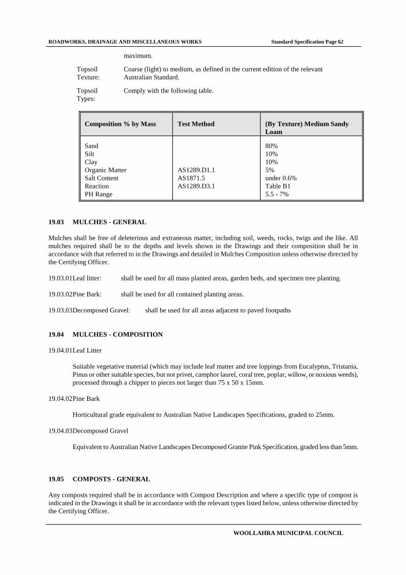
ROADWORKS, DRAINAGE AND MISCELLANEOUS WORKS Standard Specification Page 62
WOOLLAHRA MUNICIPAL COUNCIL
maximum.
Topsoil
Texture:
Coarse (light) to medium, as defined in the current edition of the relevant
Australian Standard.
Topsoil
Types:
Comply with the following table.
Composition % by Mass
Test Method
(By Texture) Medium Sandy
Loam Sand
Silt
Clay
Organic Matter
Salt Content
Reaction
PH Range
AS1289.D1.1
AS1871.5
AS1289.D3.1
80%
10%
10%
5%
under 0.6%
Table B1
5.5 - 7%
19.03 MULCHES - GENERAL
Mulches shall be free of deleterious and extraneous matter, including soil, weeds, rocks, twigs and the like. All
mulches required shall be to the depths and levels shown in the Drawings and their composition shall be in
accordance with that referred to in the Drawings and detailed in Mulches Composition unless otherwise directed by
the Certifying Officer.
19.03.01 Leaf litter: shall be used for all mass planted areas, garden beds, and specimen tree planting.
19.03.02 Pine Bark: shall be used for all contained planting areas.
19.03.03 Decomposed Gravel: shall be used for all areas adjacent to paved footpaths
19.04 MULCHES - COMPOSITION
19.04.01 Leaf Litter
Suitable vegetative material (which may include leaf matter and tree loppings from Eucalyptus, Tristania,
Pinus or other suitable species, but not privet, camphor laurel, coral tree, poplar, willow, or noxious weeds),
processed through a chipper to pieces not larger than 75 x 50 x 15mm.
19.04.02 Pine Bark
Horticultural grade equivalent to Australian Native Landscapes Specifications, graded to 25mm.
19.04.03 Decomposed Gravel
Equivalent to Australian Native Landscapes Decomposed Granite Pink Specification, graded less than 5mm.
19.05 COMPOSTS - GENERAL
Any composts required shall be in accordance with Compost Description and where a specific type of compost is
indicated in the Drawings it shall be in accordance with the relevant types listed below, unless otherwise directed by
the Certifying Officer.
ROADWORKS, DRAINAGE AND MISCELLANEOUS WORKS Standard Specification Page 63
WOOLLAHRA MUNICIPAL COUNCIL
19.06 COMPOSTS - COMPOSITION
Well rotted vegetative material or animal manure, or other approved material, free from harmful chemicals, grass and
weed growth, and with a neutral pH value. If required, a certificate of compost pH value shall be provided to the
Certifying Officer.
19.06.01 Mushroom Compost
Shall be spent mushroom compost typical of the compost used throughout the mushroom growing industry
with a neutral pH value free from grass and weed growth.
19.06.02 Composted Sawdust
Shall be typical of that used in the Nursery Industry as an admix for potting mix. It shall have been treated in
accordance with NSW Department of Agriculture guidelines leached for a minimum of 12 weeks with a pH
restricted to a range of 6 - 6.5.
19.06.03 Pine Bark Fines
Shall be recovered from the screening process of pine bark. They shall not be recent screenings but aged to
the point of partial breakdown so that if wet they do not float.
19.06.04 Composted Manure
Shall be aged and composted with no toxic components, free from seeds and reproductive parts of weeds.
19.07 PLANTS
Plants shall be vigorous, well established, hardened off, of good form consistent with species or variety, not soft or
forced, free from disease and insect pests, with large healthy root systems and no evidence of having been restricted
or damaged. Trees shall have a single leading shoot.
19.07.01 Substitutions:
No substitutions to either plant size or species shall be made, unless otherwise directed by the Certifying
Officer.
19.07.02 Replacements:
Sufficient quantities of plants shall be ordered to allow for plant failures. Any plants which fail or are
damaged during the work shall be replaced with plants of the same specific type, quality and size , unless
otherwise directed by the Certifying Officer.
19.07.03 Warranty:
A warranty from the supplier shall be provided to the Certifying Officer attesting that the plants are true to
the specified species and type, and free from diseases, pests, weeds, and the like.
19.07.04 Storage:

ROADWORKS, DRAINAGE AND MISCELLANEOUS WORKS Standard Specification Page 64
WOOLLAHRA MUNICIPAL COUNCIL
Wherever possible plants shall be planted immediately after delivery to the site. If this is not possible, they
are to be kept in good condition by appropriate storage methods in order to prevent theft, drying out or
damage from any cause including, but not limited to, frost, wind, sun, vermin, animals and the like.
19.08 PLANT CONTAINERS
Sizes: Plant material shall comply with the sizes specified in the Drawings and conform with the following
characteristics:
19.08.01 Super Advanced Trees
200 Litre - Shall be in container sizes minimum 200 litres and shall have a well developed straight stem,
minimum calliper 60mm. Trees shall be well shaped with a densely foliaged crown minimum height 4.5
metres.
100 Litre - Shall be in container sizes minimum 100 litres and shall have a well developed straight stem,
minimum calliper 38mm. Trees shall be well shaped with a densely foliaged crown minimum height 3
metres.
35 Litre - Shall be in container sizes minimum 35 litres (350 x 380mm pot or equivalent plastic bag) and
shall have a well developed straight stem, minimum calliper 18mm. Minimum height 1200mm.
25 Litre - Shall be in container sizes minimum 25 litres (300 x 340 pot or equivalent plastic bag) and shall
be a minimum of 1 metre in height.
19.08.02 Super Advanced Shrubs
25 Litre - Shall be in container sizes minimum 25 litres (300 x 340 pot or equivalent plastic bag) and shall
be a minimum of 750mm in height.
15 Litre - Shall be in container sizes minimum 15 litres ( 250 x 230mm pot or equivalent plastic bag) and
shall be a minimum of 600mm in height.
5 Litre - Shall be well established container grown plants with a single leading shoot well furnished with
buds and leaves of a height not less than 400mm. Container size shall be 240 x 240mm pots, 200 x 230mm
plastic bags or equivalent 5 litre containers.
19.08.03 Advanced Shrubs/Ground Covers
2.5 Litre - Shall be in container sizes minimum 2.5 litre (150mm x 152 x 152mm pot). Shall have a strong
primary shoot well furnished with leaves, with developing secondary shoots and shall be a minimum of
200mm in height.
19.08.04 Tubestock
Tubestock: shall be in a minimum 100mm x 75mm growtubes with a strong leading shoot. Plants shall not
be overgrown and leggy.
19.09 PLANTING - GENERAL
Planting shall only be carried out after subgrade preparation as shown in the Drawings has been completed and any
required soil spreading has been carried out. Planting shall be done in accordance with the relevant Drawings.
19.10 SOIL SPREADING
ROADWORKS, DRAINAGE AND MISCELLANEOUS WORKS Standard Specification Page 65
WOOLLAHRA MUNICIPAL COUNCIL
19.10.01 Mass Planted Areas
Planting soil shall be spread and progressively tamped in order to avoid later subsidence. The spread soil
shall be thoroughly watered to prevent voids. The surface shall be raked over lightly to attain finished
profiles. The surface of the planting soil shall be finished at a level which allows the surface of the 75mm
thickness of mulching material to be at the same level as adjacent finished levels.
19.10.02 Turf Areas
The specified planting soil shall be spread on the prepared subgrade, consolidated to avoid later subsidence
and raked over lightly to obtain the finished profile. Planting soil shall finish at the same level as adjacent
finished surfaces.
19.11 MULCH SPREADING
Mulch shall be spread and rolled so that after settling, or after rolling, it is:
Smooth and evenly graded between design surface levels;
Flush with adjacent finished levels;
Of the required depths, and
Sloped towards the base of plant stems in plantation beds, but not in contact with the stem.
19.12 STAKES AND TIES - GENERAL
Stakes and ties shall be used when planting any super advanced tree of 35 litres or more unless otherwise directed by
the Certifying Officer. Materials and workmanship shall be in accordance with the relevant Drawing and the
information specified below.
19.12.01 Stakes:
Stakes shall be durable hardwood (30 x 38 x 1800mm), straight, free from knots or twists and pointed at one
end. There shall be a minimum of two per plant.
19.12.02 Ties
Ties shall be 50mm hessian webbing. Ties shall be fixed securely to stakes in a figure of eight pattern, with
the lowest tie 300mm above ground. Other ties shall be where necessary to stabilise the plant or as directed
by the Certifying Officer.
19.13 TURFING - GENERAL
Turf shall be obtained from a specialist grower of cultivated turf. Only turf of even thickness and free from weeds and
other foreign matter shall be used. A warranty from the grower certifying that the turf is free of weeds or other foreign
matter shall be provided to the Certifying Officer.
19.13.01 Preparation
Subgrade preparation and soil requirements shall be as specified in the Drawings.
19.13.02 Species
Species shall be as specified in the Drawings.
19.13.03 Laying
ROADWORKS, DRAINAGE AND MISCELLANEOUS WORKS Standard Specification Page 66
WOOLLAHRA MUNICIPAL COUNCIL
The turf shall be layed as follows:
In "stretcher pattern" with the joints staggered and close butted
Parallel with the long sides of level areas, and with contours on slopes.
To finish flush, after tamping, with adjacent finished surfaces of ground,
paving surfaces, edging or garden beds.
19.13.04 Rolling
After turf has been laid, it shall be rolled along the stretcher pattern using a minimum roller weight 100kg to
a maximum 500kg weight, ensuring levels shall finish at the existing adjacent finished surface levels.
19.13.05 Watering
Turf shall be watered immediately after laying. Watering shall be sufficient to moisten the topsoil to its full
depth.
19.14 IRRIGATION
Irrigation for roadside planter boxes shall be a low volume system using 200mm diameter polythene pipe
with drippers connected by "Multiflex Riser Tube" or equivalent. Drippers are to rate at 4 litres per hour and
a minimum of two drippers per square metre of planting shall be installed.
19.15 LANDSCAPE MAINTENANCE PERIOD
The landscape maintenance period shall vary according to the scope of works carried out. The table below
indicates the minimum required time for landscape maintenance and establishment. Landscaped areas shall
be maintained until, in the opinion of the Certifying Officer, all plants, turf etc are well established.
Value of Landscaping Works
Minimum Maintenance Period
(Weeks)
Below $4,999
3
$5,000 - $14,999
6
$15,000 - $29,999
10
$30,000 and over
12

ROADWORKS, DRAINAGE AND MISCELLANEOUS WORKS Standard Specification Page 67
WOOLLAHRA MUNICIPAL COUNCIL
20 PAVEMENT MARKINGS
20.01 GENERAL
The work to be executed under this part of the Specification consists of the setting out, supply, and application of
solvent based pavement paint and thermoplastic - cold applied marking material, raised pavement markers, pavement
spotting and removal of pavement marks. The work shall be carried out in accordance with the current edition of the
relevant RTA Specification . This RTA Specification shall define the pavement marks.

ROADWORKS, DRAINAGE AND MISCELLANEOUS WORKS Standard Specification Page 68
WOOLLAHRA MUNICIPAL COUNCIL
21 STREET NAME SIGNS
This specification is to be read in conjunction with Council’s Standard Drawing No SF2.
21.01 BLADE
Extruded 6mm Aluminium section blade manufactured from an approved supplier.
Blade to be 200mm deep for Type A signs and 150mm deep for Type B, C & D signs.
Blade shall have two mounting holes as specified in the Standard Drawing. Holes are to be press
punched to ensure uniformity for future replacement.
Blade lengths shall not exceed 1200mm in length, and be a minimum of 500mm in length.
Blade ends shall be cut square.
21.02 REFLECTIVE BACKGROUND MATERIAL
Class 1 (honeycomb pattern) white reflective background material (other than Type C) shall be applied to
both sides of the blade, flush with the top and bottom of the blade.
Class 1 Yellow reflective background material shall be used for Type C signs only.
The reflective material shall start 40mm from the bracket end of the blade and be cut flush with the end
of the blade.
21.03 LETTERING & LOGO
Street sign wording shall be specified at the time of individual order.
Street name abbreviations shall be in accordance with AS1742.5 – 1997, excluding Avenue and Lane, which
shall be indicated as AVE and LN respectively.
Lettering shall be Univers Bold Font in Upper and Lower case applied to both sides of the blade as per
the Standard Drawing.
Lettering shall be Black for Type A, B & C signs, and Burgundy PMS 208 for Type D signs.
Lettering shall be cleanly cut and applied in such a manner that prevents the entrapment of air under the
applied finishes.
All lettering shall be certified against breakdown or discolouration for seven years.
Woollahra Municipal Council’s corporate logo is to be applied to both sides of the blade on Type A &
B signs only, and positioned at the bracket end of the blade as per the Standard Drawing.
21.04 POLE & MOUNTING BRACKETS
Poles shall be 50mm nominal bore galvanised steel pipe, with galvanised pole caps included.
Poles unless otherwise specified shall be 3200mm in length.
Signs are to be mounted on the poles (or power pole where appropriate) at a minimum of 2.5m above
the ground level or a maximum of 3.0m above ground level.
Existing galvanised poles that are in good condition and not damaged, shall be re-used to mount new
signs. However, if the existing pole does not have sufficient length to achieve the mounting height as
ROADWORKS, DRAINAGE AND MISCELLANEOUS WORKS Standard Specification Page 69
WOOLLAHRA MUNICIPAL COUNCIL
stated above, then the pole shall be removed and a new pole installed. Existing poles that are damaged
shall be replaced.
Pre-drilled Two piece Aluminium bracket assemblies shall be supplied, complete with bolts, nuts and
washers. All materials shall be compatible with the specified blade.
21.05 INSTALLATION
Blades shall be securely fixed to the poles using the supplied bracket assemblies.
Poles shall be concreted into a footing as specified in the Standard Drawing. All poles shall be fixed
plumb.
21.06 GENERAL
This specification is to be read in conjunction with Councils official order and Councils’ Standard Drawing
No SF2.
All signs are to be double sided unless otherwise specified.
All signs shall be constructed from new, first quality materials. Blades and Reflective background material
shall carry a 12-year warranty from the manufacturer.
Protection and packaging of all blades, poles, brackets and associated materials for delivery to Council shall
be the responsibility of the supplier. Materials are to be packaged in such a manner as to prevent any damage
during transportation or delivery.
Manufacturing tolerances of signs shall be specified in Clause 4.2 of AS 1743.
Contract sign manufacturers are to obtain Council’s corporate logo from Council’s works depot.
21.07 SIGN LOCATIONS
The location of street name & supplementary signs to be used throughout the
municipality are as follows (unless specified otherwise):
Type A Street name sign - New South Head Rd
- Old South Head Rd
- Oxford St (Boundary St to Ocean St)
- Boundary St
- Glenmore Rd
- Gurner St & Hargrave St (Glenmore Rd to Jersey Rd)
- Jersey Rd
- Queen St
- Ocean St & Ocean Ave
- William St
- Edgecliff Rd
- Bellevue Rd
- Victoria Rd
- O’Sullivan Rd
- Newcastle St
- Hopetoun Ave
Type B Street name sign All other roads throughout the municipality excluding the above.
Type C & D Supplementary signs Where required. Replace at existing locations.
ROADWORKS, DRAINAGE AND MISCELLANEOUS WORKS Standard Specification Page 70
WOOLLAHRA MUNICIPAL COUNCIL
22 STANDARD DETAIL DRAWINGS
The following Standard Detail Drawings shall apply to work carried out in accordance with this STANDARD
SPECIFICATION.
RF SERIES – ROAD & FOOTPATH WORKS
RF1.1 – Standard Kerb & Gutter profiles
RF1.2 – Sandstone Kerb and Concrete Gutter Reconstruction
RF1.3 – Mountable Median Island and Kerb Extension
RF1.4 – Construction of Round-a-bout
RF2_C – Standard Residential Vehicle Crossing & Layback
RF3 – Kerb Ramps, Footpath, Kerb & Gutter reconstruction
DR SERIES – DRAINAGE WORKS
DR1 – Grated Gully Pit
DR2 – Temporary Sediment & Erosion control
DR3 – Standard Junction Pit
SF SERIES – STREET FURNITURE
SF1 – Seat detail
SF2 – Street name & supplementary signs
SF3 – Temporary construction information sign
SF4 – Bin Enclosure
MS SERIES – MISCELLANEOUS / OR FENCING
MS1 – Tubular Handrail system
MS2 – Timber Picket Fence
MS3 – Standard Tree Planting Details
MS4 – Standard Landscaped Kerb Island (under review)
MS5 – Pathway Steps
MS6 – Standard Edging Details around Tree Pits in Asphalt Footpath
MS7 – Standard Treatment Details of Street Name Plates in Construction Sites

MOUNTABLE KERB
ORIGINAL = A4 SHEET
I
W
STANDARD KERB & GUTTER PROFILES
WOOLLAHRA MUNICIPAL COUNCIL
M
U
N
I
O
P
A
L
C
C
U
N
C
IL
O
O
L
LA
H
R
A
Checked
Drawn
Scale
DateYDS
Datum
Drawing No.
-
*
*
*
EDGE RESTRAINT
KERB ONLY
DISH GUTTER
ROLL KERB & GUTTER
STANDARD KERB & GUTTER
450175150 150
10
0
900150 150
PROVIDE 5 MPa
LEAN MIX BASE
10
0
150 150150
150 150600
150 150
10
0
150
10
0
150180
260
PROVIDE 5 MPa
LEAN MIX BASE
PROVIDE 5 MPa
LEAN MIX BASE
10
0
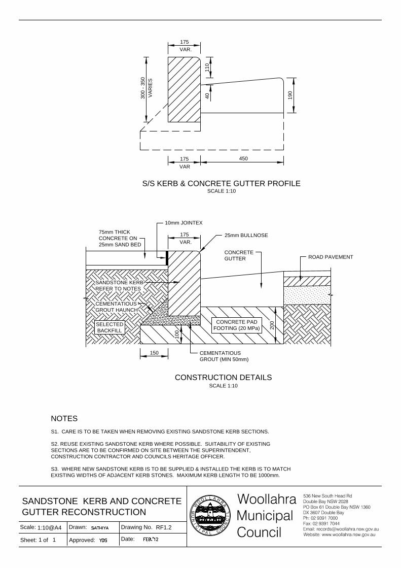
175
19
0
11
04
0
450
SCALE 1:10
30
0 - 3
50
VA
RIE
S
VAR
175
VAR.
S/S KERB & CONCRETE GUTTER PROFILE
175
CEMENTATIOUS
GROUT (MIN 50mm)
CONCRETE PAD
FOOTING (20 MPa)
150
20
0
10
0
75mm THICK
CONCRETE ON
25mm SAND BED
CEMENTATIOUS
GROUT HAUNCH
VAR.
CONCRETE
GUTTER
SANDSTONE KERB
REFER TO NOTES
SELECTED
BACKFILL
25mm BULLNOSE
SCALE 1:10
CONSTRUCTION DETAILS
ROAD PAVEMENT
10mm JOINTEX
S1. CARE IS TO BE TAKEN WHEN REMOVING EXISTING SANDSTONE KERB SECTIONS.
S2. REUSE EXISTING SANDSTONE KERB WHERE POSSIBLE. SUITABILITY OF EXISTING
SECTIONS ARE TO BE CONFIRMED ON SITE BETWEEN THE SUPERINTENDENT,
CONSTRUCTION CONTRACTOR AND COUNCILS HERITAGE OFFICER.
S3. WHERE NEW SANDSTONE KERB IS TO BE SUPPLIED & INSTALLED THE KERB IS TO MATCH
EXISTING WIDTHS OF ADJACENT KERB STONES. MAXIMUM KERB LENGTH TO BE 1000mm.
NOTES
1:10@A4
1 1
RF1.2
SANDSTONE KERB AND CONCRETE
GUTTER RECONSTRUCTION
Sheet: of
Scale: Drawn:
Approved:
Drawing No.
Date:
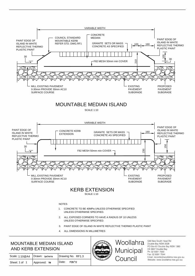
1:10@A4
1 1
RF1.3
MOUNTABLE MEDIAN ISLAND
AND KERB EXTENSION
Sheet: of
Scale: Drawn:
Approved:
Drawing No.
Date:
100
10
0
30
160
21
0
COUNCIL STANDARD
MOUNTABLE KERB
CONCRETE
MEDIAN
PROPOSED
PAVEMENT
SUBGRADE
30
MOUNTABLE MEDIAN ISLAND
SCALE 1:10
EXISTING
PAVEMENT
SUBGRADE
MILL EXISTING PAVEMENT
0-30mm PROVIDE 30mm AC10
SURFACE COURSE
REFER STD. DWG.RF1
VARIABLE WIDTH
15
0
160
23
0
CONCRETE KERB
EXTENSION
PROPOSED
PAVEMENT
SUBGRADE
GRANITE SETS OR MASS
CONCRETE AS SPECIFIED
30
F82 MESH 50mm min COVER
KERB EXTENSION
SCALE 1:10
EXISTING
PAVEMENT
SUBGRADE
MILL EXISTING PAVEMENT
0-30mm PROVIDE 30mm AC10
SURFACE COURSE
VARIABLE WIDTH
ALL EXPOSED CORNERS TO HAVE A RADIUS OF 10 UNLESS2.
UNLESS OTHERWISE SPECIFIED.
CONCRETE TO BE 40MPa UNLESS OTHERWISE SPECIFIED1.
NOTES
PAINT EDGE OF ISLAND IN WHITE REFLECTIVE THERMO PLASTIC PAINT3.
UNLESS OTHERWISE SPECIFIED.
ALL DIMENSIONS IN MILLIMETRES4.
F82 MESH 50mm min COVER
PAINT EDGE OF
ISLAND IN WHITE
REFLECTIVE THERMO
PLASTIC PAINT
PAINT EDGE OF
ISLAND IN WHITE
REFLECTIVE THERMO
PLASTIC PAINT
PAINT EDGE OF
ISLAND IN WHITE
REFLECTIVE THERMO
PLASTIC PAINT
PAINT EDGE OF
ISLAND IN WHITE
REFLECTIVE THERMO
PLASTIC PAINT
GRANITE SETS OR MASS
CONCRETE AS SPECIFIED

DETAIL "A"
F82 FABRIC MESH
50mm COVER
GRANITE SETS
25mm RESHEETING
FINISHED ROAD SURFACE
EXISTING ROAD SURFACE
R20 SMOOTH ROUND EDGE FINISH
REINFORCED WITH 2Y12 "RING"BARS
IN "WHITE" CEMENT FINISH
& R10-600 "L" BARS WITH 150 COG.
200X300mm CONC. EDGE BEAM
MOUNTABLE CENTRAL ISLAND DETAILS
SECTION A-A
1.
NOTES AND LEGEND
ALL CONCRETE ISLANDS ARE TO BE CONSTRUCTED WITH 40MPa CONCRETE(MIN.) REINFORCED WITH F82
FABRIC 50 COVER ON 150mm COMPACTED THICKNESS OF FINE CRUSHED ROCK (DGB20) OR EQIVALENT.
LENGTHS FOR TRANSPORTATION AND HANDLING. ALLOWANCE MUST BE PROVIDED FOR THE LAPPING OF RING BARS FOR PLACEMENT.
THE REINFORCING RING BAR WILL BE BENT TO THE REQUIRED RADIUS AND SPLICED TO CONVINIENT
PLAIN CONCRETE
2.
Drawn
Checked
SATHIYA
YDSFEB.'12
Datum
Date
WOOLLAHRA MUNICIPAL COUNCIL
NTSScale
RF1.4Drawing No.
3.ALL DIMENSIONS IN MILLIMETRES
BLACK COLOUR FOR THE RIM AND BORDER
REMAINDER TO BE VERDANT COLOUR
PATTERN INFILL IS TO BE OF 90X90X50 GRANITE SETS :-4.
INCLUDING ALL SPLITTER ISLANDS
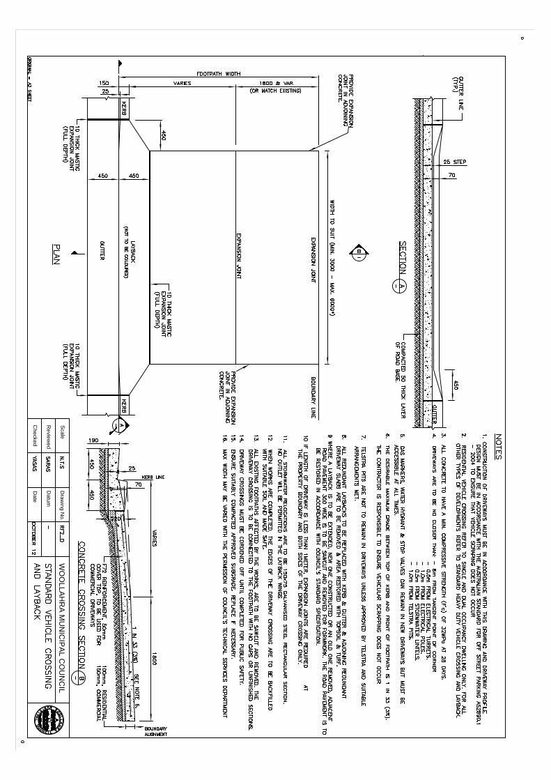
Re
vie
we
d
Ch
ecke
d
Da
tu
m
Da
te
WO
OLLA
HR
A M
UN
IC
IP
AL C
OU
NC
IL
Sca
le
Dra
win
g N
o.

ORIGINAL = A3 SHEET
Drawn
Checked
Datum
Date
E
X
P
A
N
S
I
O
N
J
O
I
N
T
WOOLLAHRA MUNICIPAL COUNCIL
ScaleDrawing No.
(OPTION B)