wordperfect document - about - u.s. department of transportation
TRANSCRIPT
Developing Traveler Information Systems
Using the National ITS Architecture
U. S. Department of Transportation
Intelligent Transportation Systems Joint Program Office
August 1998
1. Report No.
FHWA-JPO-98-031
2. Government Accession No. 3. Recipient’s Catalog No.
4. Title and SubtitleDeveloping Traveler Information Systems Using the National ITS Architecture
5. Report DateAugust 1998
6. Performing Organization Code
7. Author(s)Various
8. Performing Organization Report No.
9. Performing Organization Name and AddressMitretek Systems 600 Maryland Avenue SW, Suite 755Washington, DC 20024
TransCore, Inc.251 Park Avenue South, 14th FloorNew York, NY 10010(See Acknowledgments)
10. Work Unit No. (TRAIS)
11. Contract or Grant No.DTFH61-95-C-00040
12. Sponsoring Agency Name and AddressFederal Highway AdministrationITS Joint Program Office
400 Seventh Street, SW Washington, DC 20590
13. Type of Report and Period Covered
14. Sponsoring Agency CodeHVH-1
15. Supplementary NotesSponsoring Agency Task Manager— Lee Simmons
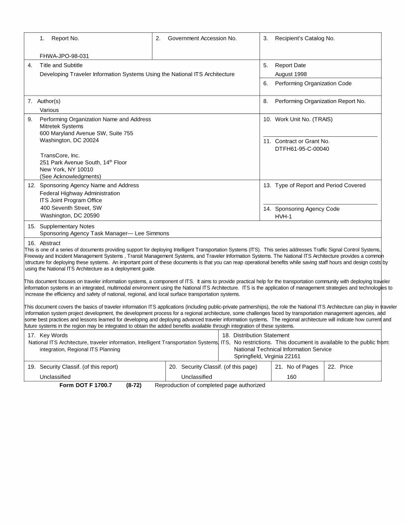
16. AbstractThis is one of a series of documents providing support for deploying Intelligent Transportation Systems (ITS). This series addresses Traffic Signal Control Systems,Freeway and Incident Management Systems , Transit Management Systems, and Traveler Information Systems. The National ITS Architecture provides a commonstructure for deploying these systems. An important point of these documents is that you can reap operational benefits while saving staff hours and design costs byusing the National ITS Architecture as a deployment guide.
This document focuses on traveler information systems, a component of ITS. It aims to provide practical help for the transportation community with deploying travelerinformation systems in an integrated, multimodal environment using the National ITS Architecture. ITS is the application of management strategies and technologies toincrease the efficiency and safety of national, regional, and local surface transportation systems.
This document covers the basics of traveler information ITS applications (including public-private partnerships), the role the National ITS Architecture can play in travelerinformation system project development, the development process for a regional architecture, some challenges faced by transportation management agencies, andsome best practices and lessons learned for developing and deploying advanced traveler information systems. The regional architecture will indicate how current andfuture systems in the region may be integrated to obtain the added benefits available through integration of these systems.
17. Key WordsNational ITS Architecture, traveler information, Intelligent Transportation Systems, ITS,
integration, Regional ITS Planning
18. Distribution StatementNo restrictions. This document is available to the public from:National Technical Information Service Springfield, Virginia 22161
19. Security Classif. (of this report)
Unclassified
20. Security Classif. (of this page)
Unclassified
21. No of Pages
160
22. Price
Form DOT F 1700.7 (8-72) Reproduction of completed page authorized
Notice
This document is disseminated under the sponsorshipof the Department of Transportation in the interest of
information exchange. The United States Governmentassumes no liability for its contents or use thereof.
Developing Traveler Information Systems Using the National ITS Architecture Technical Edition
iii
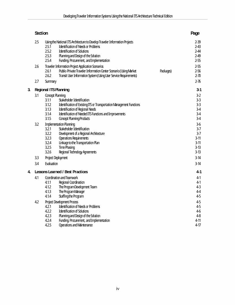
Table of ContentsSection Page
1. Introduction and Summary 1-11.1 Purpose and Intended Audience 1-1
1.1.1 Intended Purpose 1-11.1.2 What is the National ITS Architecture? 1-21.1.3 Intended Audience 1-2
1.2 Traveler Information Systems 1-31.2.1 Traveler Information System Functions 1-31.2.2 Characteristics of Effective Traveler Information Systems 1-41.2.3 Benefits of Traveler Information Systems 1-51.2.4 Challenges Facing Implementers of Traveler Information Systems 1-5
1.3 The National ITS Architecture Can Help You 1-61.3.1 Help for ITS Planners and Implementers 1-61.3.2 ITS Standards 1-8
1.4 Document Organization and Summary 1-91.4.1 Document Organization 1-91.4.2 Document Summary 1-9
2. Use of the National ITS Architecture Tools in Traveler Information Projects 2-12.1 Overview 2-12.2 Traveler Information System Applications 2-1
2.2.1 Overview 2-12.2.2 Traveler Information Requirements and Characteristics 2-32.2.3 Public-Private Partnerships 2-5
2.3 Development of Traveler Information Projects 2-152.3.1 Identification of Needs or Problems 2-152.3.2 Identification of Solutions 2-162.3.3 Planning and Design of the Solution 2-162.3.4 Funding, Procurement and Implementation 2-16
2.4 Key Concepts of the National ITS Architecture 2-172.4.1 User Services and User Service Requirements 2-182.4.2 Logical Architecture 2-202.4.3 Physical Architecture 2-232.4.4 Equipment Packages 2-312.4.5 Market Packages 2-322.4.6 National ITS Architecture Documents 2-35
Developing Traveler Information Systems Using the National ITS Architecture Technical Edition
iv
Section Page
2.5 Using the National ITS Architecture to Develop Traveler Information Projects 2-392.5.1 Identification of Needs or Problems 2-432.5.2 Identification of Solutions 2-442.5.3 Planning and Design of the Solution 2-492.5.4 Funding, Procurement, and Implementation 2-55
2.6 Traveler Information Project Application Scenarios 2-552.6.1 Public-Private Traveler Information Center Scenario (Using Market Packages) 2-562.6.2 Transit User Information System (Using User Service Requirements) 2-70
2.7 Summary 2-76
3. Regional ITS Planning 3-13.1 Concept Planning 3-2
3.1.1 Stakeholder Identification 3-33.1.2 Identification of Existing ITS or Transportation Management Functions 3-33.1.3 Identification of Regional Needs 3-43.1.4 Identification of Needed ITS Functions and Improvements 3-43.1.5 Concept Planning Products 3-4
3.2 Implementation Planning 3-63.2.1 Stakeholder Identification 3-73.2.2 Development of a Regional Architecture 3-73.2.3 Operations Requirements 3-113.2.4 Linkage to the Transportation Plan 3-113.2.5 Time Phasing 3-133.2.6 Regional Technology Agreements 3-13
3.3 Project Deployment 3-143.4 Evaluation 3-14
4. Lessons Learned / Best Practices 4-14.1 Coordination and Teamwork 4-1
4.1.1 Regional Coordination 4-14.1.2 The Program Development Team 4-34.1.3 The Program Manager 4-44.1.4 Staffing the Program 4-5
4.2 Project Development Process 4-54.2.1 Identification of Needs or Problems 4-54.2.2 Identification of Solutions 4-64.2.3 Planning and Design of the Solution 4-84.2.4 Funding, Procurement, and Implementation 4-114.2.5 Operations and Maintenance 4-17
Developing Traveler Information Systems Using the National ITS Architecture Technical Edition
v
Section Page
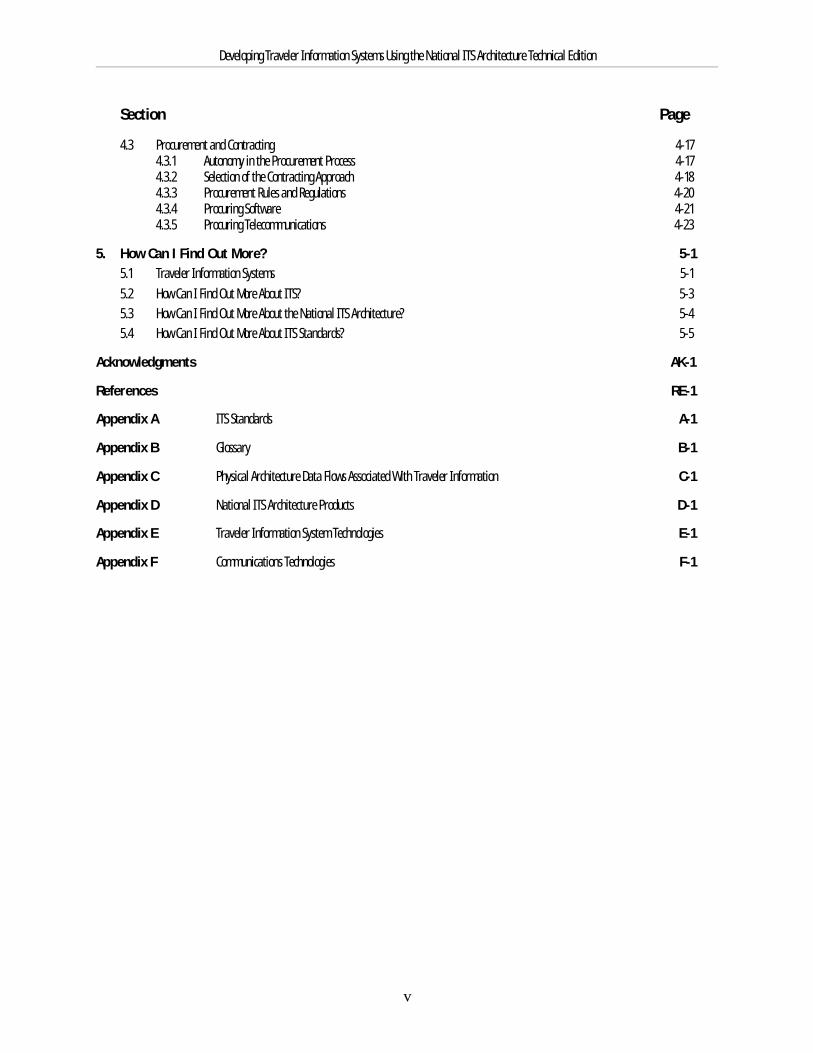
4.3 Procurement and Contracting 4-174.3.1 Autonomy in the Procurement Process 4-174.3.2 Selection of the Contracting Approach 4-184.3.3 Procurement Rules and Regulations 4-204.3.4 Procuring Software 4-214.3.5 Procuring Telecommunications 4-23
5. How Can I Find Out More? 5-15.1 Traveler Information Systems 5-15.2 How Can I Find Out More About ITS? 5-35.3 How Can I Find Out More About the National ITS Architecture? 5-45.4 How Can I Find Out More About ITS Standards? 5-5
Acknowledgments AK-1
References RE-1
Appendix A ITS Standards A-1
Appendix B Glossary B-1
Appendix C Physical Architecture Data Flows Associated With Traveler Information C-1
Appendix D National ITS Architecture Products D-1
Appendix E Traveler Information System Technologies E-1
Appendix F Communications Technologies F-1

Developing Traveler Information Systems Using the National ITS Architecture Technical Edition
vi
Developing Traveler Information Systems Using the National ITS Architecture Technical Edition
vi
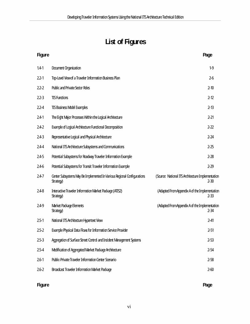
List of FiguresFigure Page
1.4-1 Document Organization 1-9
2.2-1 Top-Level View of a Traveler Information Business Plan 2-6
2.2-2 Public and Private Sector Roles 2-10
2.2-3 TIS Functions 2-12
2.2-4 TIS Business Model Examples 2-13
2.4-1 The Eight Major Processes Within the Logical Architecture 2-21
2.4-2 Example of Logical Architecture Functional Decomposition 2-22
2.4-3 Representative Logical and Physical Architecture 2-24
2.4-4 National ITS Architecture Subsystems and Communications 2-25
2.4-5 Potential Subsystems for Roadway Traveler Information Example 2-28
2.4-6 Potential Subsystems for Transit Traveler Information Example 2-29
2.4-7 Center Subsystems May Be Implemented In Various Regional Configurations (Source: National ITS Architecture ImplementationStrategy) 2-30
2.4-8 Interactive Traveler Information Market Package (ATIS2) (Adapted From Appendix A of the ImplementationStrategy) 2-33
2.4-9 Market Package Elements (Adapted From Appendix A of the ImplementationStrategy) 2-34
2.5-1 National ITS Architecture Hypertext View 2-41
2.5-2 Example Physical Data Flows for Information Service Provider 2-51
2.5-3 Aggregation of Surface Street Control and Incident Management Systems 2-53
2.5-4 Modification of Aggregated Market Package Architecture 2-54
2.6-1 Public-Private Traveler Information Center Scenario 2-58
2.6-2 Broadcast Traveler Information Market Package 2-60
Figure Page
Developing Traveler Information Systems Using the National ITS Architecture Technical Edition
vii
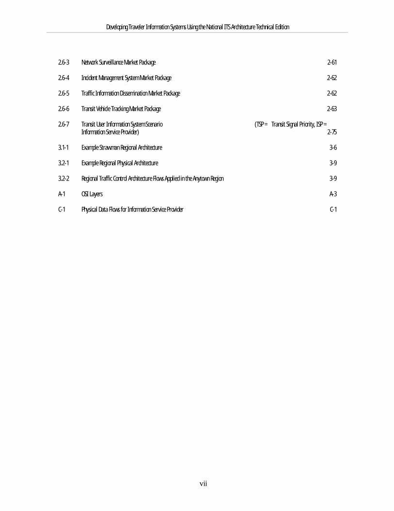
2.6-3 Network Surveillance Market Package 2-61
2.6-4 Incident Management System Market Package 2-62
2.6-5 Traffic Information Dissemination Market Package 2-62
2.6-6 Transit Vehicle Tracking Market Package 2-63
2.6-7 Transit User Information System Scenario (TSP = Transit Signal Priority, ISP =Information Service Provider) 2-75
3.1-1 Example Strawman Regional Architecture 3-6
3.2-1 Example Regional Physical Architecture 3-9
3.2-2 Regional Traffic Control Architecture Flows Applied in the Anytown Region 3-9
A-1 OSI Layers A-3
C-1 Physical Data Flows for Information Service Provider C-1

Developing Traveler Information Systems Using the National ITS Architecture Technical Edition
viii
List of TablesTable Page
1.2-1 Summary of Traveler Information System Benefits 1-5
2.2-1 Traveler Information Technologies 2-3
2.2-2 Market Forecast for Autonomous and Advisory Navigation and Guidance Systems 2-8
2.2-3 Consumer Willingness To Pay – Survey Results 2-8
2.4-1 User Services for the National ITS Architecture 2-19
2.4-2 Example of User Service Requirements: Excerpt from Pre-Trip Travel Information 2-20
2.4-3 Example Process Specifications (Overview Descriptions) 2-23
2.4-4 National ITS Architecture Subsystems Applicable to Traveler Information Systems 2-26
2.4-5 ITS Market Packages 2-36
2.5-1 Connecting Problems, Solutions, and the National Architecture (Excerpt from Table 4.2-1 of theImplementation Strategy) 2-49
2.6-1 Cost Spreadsheet for the Broadcast Information Broadcast Equipment Package 2-66
2.6-2 Cost Summary for Traveler Information System Scenario 2-67
2.6-3 Cost for Interactive Traveler Information (ATIS2) Market Package 2-68
2.6-4 Cost for Traffic Information Dissemination (ATMS6) Market Package 2-69
E.4-1 In-Vehicle Information Needs E-15

Developing Traveler Information Systems Using the National ITS Architecture Technical Edition
1. Introduction and Summary1.1 Purpose and Intended AudienceThis is one of a series of documents providing support for deploying Intelligent Transportation Systems (ITS). This series addresses:
g Traveler Information Systems
g Traffic Signal Control Systems
g Freeway and Incident Management Systems
g Transit Management Systems
The National ITS Architecture provides a common structure for deploying these systems. An important point of these documents is that you can reapoperational benefits while saving staff hours and design costs by using the National ITS Architecture as a deployment guide.
1.1.1 Intended PurposeThis document focuses on traveler information systems, a component of ITS. It aims to provide practical help to the transportation community withdeploying traveler information systems in an integrated, multimodal environment using the National ITS Architecture. ITS is the application ofmanagement strategies and technologies to increase the efficiency and safety of national, regional, and local surface transportation systems. IntelligentTransportation Systems form the basis for a new way of doing business in addressing the nation’s surface transportation needs. Rather than solvingtransportation challenges solely by building additional roadway capacity, ITS strategies strive to use roadway facilities more efficiently by applyingtechnology and effective management strategies to collect, transfer, process, and share historic and real-time transportation information. This includes theuse of computer, communications, sensor, information, and control technologies and a structured approach to manage the planning, development,deployment, operations, and maintenance of ITS systems and projects. Traveler information systems can be enhanced by promoting innovativepublic/private partnerships, which involves leveraging of the resources from both sides of these partnerships to mutual advantage.
This document is designed as a guide for how the National ITS Architecture can be used in the process of designing, developing, and implementing effectivetraveler information systems. Development of the National ITS Architecture arose out of a need to provide a common framework for deployment of ITSacross the nation. The National ITS Architecture contains the information you need to develop a regional architecture, to be assured you haven’toverlooked anything important, and to ensure you are preparing an efficient deployment. This document shows how to enhance existing and emergingtraveler information systems, facilitate design and upgrade of future systems, and help overcome challenges commonly faced by transportation agenciesinvolved in the delivery of traveler information systems. This document covers the basics of traveler information ITS applications, the role the National ITSArchitecture can play in traveler information system project development, the development process for a regional architecture, and some best practicesand lessons learned for developing and deploying traveler information systems. The regional architecture will help to indicate how current and futuresystems in the region may be integrated to obtain the added benefits available through integration of these systems.
1.1.2 What is the National ITS Architecture? The National ITS Architecture defines the components of the surface transportation system, how they interact and work together, and what informationthey exchange to provide 30 ITS user services. These 30 user services have been identified by the U.S. ITS community as part of the National ITS Programto guide the development of ITS and are listed in Section 2. A key requirement for development of the National ITS Architecture [FHWA, January 1997] wasthat it include the transportation functions necessary to provide the 30 user services.
Developing Traveler Information Systems Using the National ITS Architecture Technical Edition
Using the National ITS Architecture will save implementers time and money because it contains much of the up front analysis and planning informationnecessary to deploy ITS, including project definition and requirements, information exchange requirements, system evaluation criteria, cost developmentinformation, communications analysis, and benefits of deployment of specific ITS applications.
1.1.3 Intended AudienceThe intended audience of this document includes:
g Mid-level administrators and transportation engineers for state and local transportation agencies involved in planning, designing,implementing, operating and maintaining transportation management systems, including the ITS components that can interface with andprovide information to traveler information systems.
g Transportation professionals and others interested in understanding traveler information systems challenges and solutions based on theArchitecture.
g Managers, transportation engineers, and system engineers in private enterprises with interests in working with public partners with anobjective to establish and operate traveler information systems.
If your work involves planning, designing, implementing, operating or maintaining traveler information systems or transportation management systems,and you perform one of the following functions within your organization, this document is intended for you:
Developing Traveler Information Systems Using the National ITS Architecture Technical Edition
Regional Transportation Planning Project Planning and Development
Traffic or Transit Operations, Maintenance Traffic or Transit Engineering
Public/Private Partnerships Project Management
Project Implementation Project Approval
Preliminary and Final Analysis and Design ITS Project Definition
Procurement of Services and Equipment Project Acceptance Testing
Project Evaluation
1.2 Traveler Information Systems Effective traveler information systems are multimodal and support many categories of drivers and travelers. They apply many technologies to allowcustomers to receive roadway, transit network, and other information important to their trip. This information assists the customers in selecting theirmode of travel (car, train, bus, etc.), route and departure time. Transit schedule and status information may be obtained from Transit ManagementSystems. Most of the roadway-based information is collected by surveillance equipment (vehicle detectors, cameras, automated vehicle location systems)and is processed by computers in transportation management centers for further distribution to traveler information systems. Other information used in atraveler information system may be static in nature, such as; map databases, emergency services information, and information on motorist services andtourist attractions and services. The technologies for requesting, receiving, and interacting with all of this information can be based in the home, office,passenger vehicle, commercial vehicle, transit vehicle, public transit station, or in the case of personal communication devices, can travel with a person.
1.2.1 Traveler Information System FunctionsEffective traveler information systems provide multi-modal trip planning, route guidance, and advisory functions for travelers and drivers of all types. They also may enable travelers to confirm and pay for services and may include personal emergency notification capabilities. Trip planning informationand assistance may be provided pre-trip or en-route. Pre-trip planning assistance provides travelers with roadway information, including road condition,traffic information and travel times, and transit information which can be used to select route, mode, and departure time. This support may be requestedfrom home, the workplace, park and ride facilities, transit stations, and other locations. En-route traveler assistance provides the traveler with roadwayand transit information while traveling, including traffic information, roadway conditions, transit information, route guidance information, and otherinformation such as adverse travel conditions, special events, and parking.
Developing Traveler Information Systems Using the National ITS Architecture Technical Edition
Below are descriptions of the top level functions performed by advanced traveler information systems.
g Multi-Modal Trip Planning - provides region wide information and assists trip planning by travelers including private car and traditional transitmodes, plus rideshare matching and reservation and demand responsive transit reservation. Links to information and reservation services mayenable travelers to include heavy rail and airlines as part of their trip planning.
g Route Guidance Services and Information - autonomous or dynamic (supported with real-time information) modes of on-line guidance provideroute planning and turn-by-turn directions and other navigation assistance. Current roadway link travel times may be provided directly todrivers, allowing selection of routes to avoid the worst congestion or other adverse conditions.
g Advisory Functions - advisories may include incident warnings, delay notifications, anticipated travel times to destination (accounting for real-time conditions) and to next intermodal connection (e.g. transit stop), adverse travel condition advisories, intermodal connections and scheduleadherence, CVO restrictions (height, weight and hazmat), parking information and status, identification of next few transit stop locations (if ontransit), upcoming tolls, etc.
g Interfaces with Traffic Management Systems in the region to obtain traffic, incident, and roadway information on both freeways and arterialsand with Transit Management Systems in the region to obtain transit information, including schedules and status. This information may beaugmented with additional surveillance information and information from numerous other sources.
1.2.2 Characteristics of Effective Traveler Information SystemsInterviews with traveler information system operators and travelers have identified some key features of effective traveler information systems. Effectivetraveler information systems:
g Provide information that is timely, accurate, reliable, relevant to making travel decisions, and marketable.
g Provide information for the entire region. This requires the participation of public agencies across jurisdictional boundaries.
g Operate with efficient, well-trained staffs.
g Are integrated easily with other ITS systems—emergency management, freeway management, traffic signal control, and transitmanagement—to obtain adequate traveler information.
g Are easy to use and easy to access by the traveling public.
g Are easy to maintain (with in-house or contract resources) and do not require excessive costs and time to operate. Ideally, traveler informationcomponents need to be interoperable between different manufacturers and vendors. This reduces maintenance costs and provides addedflexibility in repairing equipment faults and malfunctions, finding spare parts, and developing system upgrade paths.
g Provide services that are affordable to end users.
1.2.3 Benefits of Traveler Information SystemsIn general, each traveler information system must be designed to meet the specific social and political objectives of each community. Many travelerinformation systems strive to
g .
Developing Traveler Information Systems Using the National ITS Architecture Technical Edition
g Reduce intermodal travel times and delays for individual travelers.
g Reduce traveler stress for trips to unfamiliar destinations.
g Reduced crash risk and fatalities (e.g. reduced driver distraction in unfamiliar routes).
g Reduce overall system travel times and delays.
g Reduce system costs through public-private partnerships.
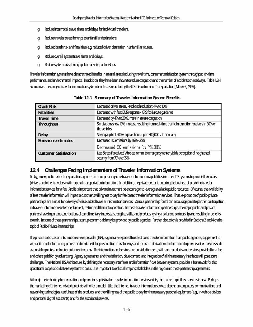
Traveler information systems have demonstrated benefits in several areas including travel time, consumer satisfaction, system throughput, on-timeperformance, and environmental impacts. In addition, they have been shown to reduce congestion and the number of accidents on roadways. Table 1.2-1summarizes the range of traveler information system benefits as reported by the U.S. Department of Transportation [Mitretek, 1997].
Table 1.2-1. Summary of Traveler Information System Benefits
Crash Risk Decreased driver stress, Predicted reduction: 4% to 10%Fatalities Decreased with fast EMS response - GPS fix & route guidanceTravel Time Decreased by 4% to 20%, more in severe congestionThroughput Simulations show 10% increase resulting from real-time traffic information receivers in 30% of
the vehiclesDelay Savings up to 1,900 v-h peak hour, up to 300,000 v-h annuallyEmissions estimates Decreased HC emissions by 16%–25%
Customer Satisfaction Less Stress Perceived; Wireless comm. to emergency center yields perception of heightenedsecurity from 70% to 95%
1.2.4 Challenges Facing Implementers of Traveler Information SystemsToday, many public sector transportation agencies are incorporating some traveler information capabilities into their ITS systems to provide their users(drivers and other travelers) with regional transportation information. In addition, the private sector is entering the business of providing travelerinformation services for a fee. And it is important that private investment be encouraged to leverage available public resources. Of course, the availabilityof free traveler information will impact a customer’s willingness to pay for fee-based traveler information services. Thus, exploration of public-privatepartnerships are a must for delivery of value-added traveler information services. Various partnership forms can encourage private partner participationin traveler information system deployment, testing and then into operation. In these traveler information partnerships, the major public and privatepartners have important contributions of complimentary interests, strengths, skills, and products, giving a balanced partnership and resulting in benefitsto each. In some of these partnerships, startup economic aid may be provided by public agencies. Further discussion is provided in Sections 2 and 4 on thetopic of Public-Private Partnerships.
The private sector, as an information service provider (ISP), is generally expected to collect basic traveler information from public agencies, supplement itwith additional information, process and combine it for presentation in useful ways and for use in derivation of information to provide added services suchas providing routes and route guidance directions. The information and services are provided to users, with some products and services provided for a fee,and others paid for by advertising. Agency agreements, and the definition, development, and integration of all the necessary interfaces will pose somechallenges. The National ITS Architecture, by defining the necessary interfaces and information flows between systems, provides a framework for thisoperational cooperation between systems to occur. It is important to enlist all major stakeholders in the region into these partnership agreements.
Although the technology for generating and providing sophisticated traveler information services exists, the marketing of these services is new. Perhapsthe marketing of Internet-related products will offer a model. Like the Internet, traveler information services depend on computers, communications andnetworking technologies, usefulness of the products, and the willingness of the public to pay for the necessary personal equipment (e.g., in-vehicle devicesand personal digital assistants) and for the associated services.
Developing Traveler Information Systems Using the National ITS Architecture Technical Edition
1.3 The National ITS Architecture Can Help You
1.3.1 Help for ITS Planners and ImplementersSimilar to a model home blueprint, the National ITS Architecture provides a common structure for the design and implementation of ITS. The National ITSArchitecture defines the functions (e.g., gather traffic information) that must be performed by components or subsystems, where these functions reside(e.g., roadside, traffic management subsystem, in-vehicle, information service provider, etc.), the interfaces and information flows between subsystems,and the communications requirements for the information flows (e.g., wireline or wireless). Just as the model home design is often changed to meet theneeds and living space requirements of individual families, the common structure provided by the National ITS Architecture can be tailored to meet aregion’s unique transportation needs.
In addition, the National ITS Architecture identifies and specifies requirements for standards needed to support national and regional interoperability, aswell as product standards needed to obtain a plug and play capability to yield economy of scale considerations in deployment. These standards will includethe formal definition of the physical interfaces and information exchange requirements of the National ITS Architecture.
A lot of time and effort went into developing the National ITS Architecture—for a very good reason—to makethe process of designing and implementing these systems easier for you.
YOU CAN SAVE STAFF HOURS AND ENGINEERING DESIGN COSTS BY USING IT.
Developing Traveler Information Systems Using the National ITS Architecture Technical Edition
g Correlates services and requirements to subsystems and data flows, thus providing traceability for a project to the selected architecture.
g Illustrates the benefits that can be obtained through efficient grouping of ITS functions plus sharing of information for multiple purposes acrossthe transportation system, avoiding redundancy and saving money.
g Provides a view into the future to identify services and functionality that may not have been initially considered, currently needed, or evenfeasible. This provides a checklist of future capabilities that could be planned for now in anticipation of future needs. Planning for thesefuture needs in database and interface designs will save substantial costs of modifications needed for these later additions.
g Provides an extensive list of the transportation agencies (by matching the functions they perform with the corresponding subsystem names inthe National ITS Architecture) that you should consider talking to during initial planning of an implementation (i.e., the stakeholders).
g Defines the kind of information that may be available from or obtainable by agencies and that one should consider sharing with theseagencies. You can use this information as a checklist in planning the traveler information project and in discussions with other stakeholders toshow how they can participate through sharing of the information.
g Serves as a good starting point or template (which can be tailored) for developing the regional architecture that will drive the designs forspecific projects. Starting with the National ITS Architecture, one can merely delete the functions and information flows that do not apply andthen incorporate any specific local requirements and considerations. This is more fully addressed in Section 3.
g Provides a departure point for developing functional requirements and system specifications to be included in a procurement package,including identification of the interfaces (some of which may have approved standards or standards work under way) and data exchanges thatmust be included.
g Provides ballpark estimates of costs for a wide range of ITS-related equipment and services that can be considered for initial project costing.
g Can support a check on the product being provided by a design contractor (if the contractor is asked to demonstrate the use of the National ITSArchitecture and its relationship to the design being offered).
Developing Traveler Information Systems Using the National ITS Architecture Technical Edition
Using the National ITS Architecture and ITS standards will provide broad, long term benefits:
g Interoperability: The National ITS Architecture has identified where standards are needed to provide a sound foundation for systeminteroperability (interfaces and products). Because the National ITS Architecture is serving as the common foundation for ongoing ITSstandards development work, factoring it into your current system enhancements will facilitate the transition to a standard interface definitionin the future. Using standard interfaces will provide for national and regional interoperability and even interchangeability of some devicesused in ITS traffic management, even though they may be from different manufacturers.
g Increased competition: By requiring use of open standards (non-proprietary), multiple vendors will be able meet the standards andbe able to respond to RFPs. Support and upgrades will also be available from multiple potential sources, avoiding the problems of being lockedin to one source (e.g., the vendor goes out of business).
g Future expandability: By designing within a common framework and using open standards, you will create an environment thatintegrates legacy systems with new ITS applications and allows more functionality to be added as needed.
g Lower costs: ITS equipment and device compatibility will create larger total markets attracting more suppliers resulting in more capableproducts at lower prices. The resulting long-term costs of deployment will be pushed down by these economies of scale for off-the-shelf ITSequipment and products and by competition through open-system enabling of multiple vendors.
g Increased transportation system integration: The open nature and structure of the National ITS Architecture and use ofstandards-compliant components will make integration of complex traffic management components and regional systems easier. Improvedintegration of systems operated by different agencies will permit effective information sharing and more effective use of resources. Seamlesstraveler services across agency lines will become a reality.
g Assistance in project development and regional planning activities: As evidenced from the above discussion, theNational ITS Architecture can be usefully applied to both project development and longer term regional planning activities. Accordingly, thisdocument will address these activities in two separate sections for clarity and ease of reference for the reader.
1.3.2 ITS StandardsUsing the National ITS Architecture to plan, design, deploy, and integrate traveler information systems will help ensure that your system will be compatiblewith existing, planned, and future systems in your region. Your traveler information system will also have an open systems architecture, use industry-accepted standards and interfaces wherever they exist, and will minimize reliance on proprietary information, interfaces, and protocols. Ultimately, thesestandards will promote national interoperability of some key services to ensure that travelers from outside your region will also be able to benefit from theITS services you provide. Consistent with the National ITS Architecture, the U.S. DOT is supporting and guiding development of selected ITS standards byfunding Standards Development Organizations (SDOs).

Section 1:Introduction
Section 2:Using Architecture Toolsin Traveler InformationProjects
Section 3: Regional ITS
Planning
Section 4:Best Practices
Lessons Learned
Section 5:How do I Find Out More?
Appendices
A: ITS StandardsB: GlossaryC: Applicable Physical Architecture Data Flows
What is ITS?What is the National ITS Architecture?
How are Traveler Informationfunctions represented in the
architecture?
How do you use the architectureto develop these projects?
How do you plan for ITS in a Region?How do you deploy an ITS Project?
D: National ITS Architecture Products
ITSNational ITS ArchitectureITS Standards
Teamwork and CoordinationProject Development ProcessProcurement and Contracting
E: TIS TechnologiesF: Communications
Technologies
Developing Traveler Information Systems Using the National ITS Architecture Technical Edition
1.4.1 Document OrganizationThis document is divided into five major sections with the content of the document as illustrated in Figure 1.4-1.
Figure 1.4-1. Document Organization
1.4.2 Document SummaryThis document covers many important areas and you are encouraged to read the entire document. However, if you are unable to do so, the summarypresented below will point you in the direction to find the information you are seeking.
For example:
g If you are beginning a major traveler information system project, proceeding to review Sections 2 and 4 might be best.
g If you are involved in long-term planning of your regional transportation system, starting your review with Section 3 might be best.
Section 1: Introduction and Summary
Section 1 briefly discusses ITS, the National ITS Architecture, benefits of traveler information systems, some challenges facing implementers, travelerinformation system functions, and briefly discusses capabilities provided by the National ITS Architecture and why you should use it.
T ITS uses a combination of management strategies and computer, communications, surveillance, and control technologies to increase theefficiency of national, regional, and local surface transportation systems.
T There are a growing number of successful ITS traveler information system projects yielding some very encouraging benefits.
T The development of traveler information systems faces many challenges, best addressed from the vantage point of public/private partnershipsinvolving representatives of all transportation agencies, of elected community representatives, and of all agencies that might benefit from orneed the support of timely distribution of traveler information to a broad community, including both broadcast and route oriented distribution.
Developing Traveler Information Systems Using the National ITS Architecture Technical Edition
T Using the National ITS Architecture as a tool in developing your traveler information systems will help provide for ease of additions ofinterfaces to future subsystems.
T The Architecture supports integration of surface transportation systems. This includes, for example, the integration of traveler informationsystems with traffic signal control, freeway management, incident management, transit management, highway-rail coordination, and parkingmanagement systems.
Section 2: Use of the National ITS Architecture Tools in Traveler Information Projects
Section 2 identifies the functions of traveler information systems as defined by the National ITS Architecture. The section then explains how theArchitecture can be used to develop ITS traveler information applications. Some representative scenarios are used as examples to help you use theNational ITS Architecture.
T Traveler information is collected by various types of surveillance equipment, is usually processed by computers, and may be distributed as pre-trip and/or en-route information. Very briefly summarized are the basic types of information dissemination systems and the many visual andaudio dissemination technologies that may be employed. Technologies and communications are described further in appendices.
T Public-private partnerships are discussed from the perspective of Traveler Information Business Models. The complimentary nature oftraveler, private sector and public sector resources, motivations, expectations and benefits is described. Roles are described as public, privateand public-private partnering and a few important institutional/legal issue areas are described
T The National ITS Architecture provides a common structure for the deployment of ITS; it defines 19 interconnected physical subsystems, thetransportation functions each subsystem performs, and the information subsystems exchange with each other to provide 30 user services.
T The functions associated with traveler information systems reside in many subsystems of the National ITS Architecture including the centersubsystems (such as the Information Service Provider Subsystem), vehicle subsystems, roadside subsystems, and traveler subsystems (such asthe Personal Information Access Subsystem and the Remote Traveler Support Subsystem).
T The National ITS Architecture can be applied to most project development steps, and is particularly helpful in the identification of solutions andthe planning and design of the solution.
T The Architecture only defines the functions that each physical subsystem performs plus the interfaces and data flows between them. Designershave complete freedom in deciding which functions are required for their needs, what equipment to use to implement the selected functions,and what technologies will be used. Designers are encouraged to be compatible with the Architecture and with ITS standards to achieveinteroperability, to provide for future enhancements and expandability, and to obtain the long-term benefits of higher quality and lower costsfrom expanding market and competition economies of scale.
Section 3: Regional ITS Planning
Section 3 describes planning for ITS applications and formulating ITS projects in a regional context.
T Using the National ITS Architecture provides a good starting point for developing a regional architecture in the transportation planning arena.
T Involving comprehensive representation of regional transportation stakeholders in developing a regional architecture to address needs andproblems can produce broad cooperation.
T Developing a regional architecture can guide development of ITS within a region and produce agreement on roles and responsibilities, phasingconsiderations for the most effective implementation of planned ITS capabilities, and regional agreements on technology and standards thuspromoting interoperability and higher levels of benefits.
Developing Traveler Information Systems Using the National ITS Architecture Technical Edition
Section 4: Lessons Learned / Best Practices
Section 4 provides advice on developing and implementing traveler information projects using lessons from agencies that have developed and implementedITS systems, or are currently developing and implementing ITS projects, plus lessons and best practices information from relevant areas of other civil anddefense technology projects. Information is provided on various topics in ITS relevant to the deployment of traveler information systems.
T Stakeholder involvement and coordination, plus teamwork and selecting the right project staff may be the keys to success on any ITS project. This is even more true in traveler information projects, since the TIS needs to interface with all systems having information relative to travelingin the region and special relationships between the public and private parties must be defined and made to work.
T Fundamental steps used by transportation agencies in the formulation and implementation of projects involve assessing problems or needs,the search for, analysis of, and selection of a solution, design of the project, and finally, the funding, procurement and implementation. Theseare the same process steps described in Section 2.
T Transportation agencies face many impediments in the procurement and contracting of developing projects, as procedures, controls andmeasures which have been put into place over the years for construction projects have had to be accommodated. However, there is some relieffor these impediments. This section sheds some light on the more common problems that have been experienced, and some of the lessons thatexperience has provided.
Section 5: How Do I Find Out More?
Section 5 shows readily accessible places to find additional information on traveler information systems, ITS, the National ITS Architecture, and ITSStandards.
References
These references pages provide a brief listing of references that may be important to those involved in any of the key roles or activities involved inplanning, development and deployment of a traveler information system.
Appendices
Finally, this document contains six appendices: Appendix A discusses ITS Standards; Appendix B provides a Glossary; Appendix C presents the PhysicalArchitecture Data Flows associated with traveler information systems; and Appendix D is a synopsis of each of the 16 volumes that make up the NationalITS Architecture documentation. The remaining two appendices, Appendices E and F, provide some background on traveler information andcommunications technologies, respectively.
T ITS Standards described in Appendix A are those applicable to traveler information systems. ITS standards have been and are being developedto support the integration of transportation systems. ITS standards should be used to help ensure interoperability of ITS subsystems anddevices plus interchangeability of like devices.
T Physical Architecture Data Flows listed in Appendix C indicate the information that is intended by the National ITS Architecture to flow acrossinterfaces of traveler information systems with other transportation systems in the region, including traffic signal control systems, freewaymanagement systems, and transit management systems.
Developing Traveler Information Systems Using the National ITS Architecture
2. Use of the National ITS Architecture Tools in TravelerInformation Projects
2.1 OverviewThis chapter presents the details of how the National ITS Architecture can be applied to traveler information system project development activities. Anoverview of traveler information systems and a general project development process is presented first to establish the context for this chapter. Next, thekey concepts of the National ITS Architecture are discussed to ensure that the reader understands the fundamentals and structure of the tool. The followingsection then shows how to apply the National ITS Architecture concepts and databases to the various steps presented in the general project developmentprocess. Lastly, two project application scenarios are presented which use realistic examples to illustrate the points made in the previous sections.
2.2 Traveler Information System Applications This section provides an overview of the various traveler information services and technologies, a discussion of the key requirements and characteristics ofeffective traveler information systems, and a discussion of the very important topic of public-private partnerships in the delivery of traveler information.
2.2.1 OverviewTraveler information technologies allow travelers (and soon-to-be travelers), to receive roadway and transit network information. There are two basiccategories of traveler information: pre-trip and en-route. These categories and the type of information provided under them are based on wheninformation is obtained relative to the start of a trip.
2.2.1.1 Pre-Trip Traveler InformationPre-trip planning systems provide travelers with roadway and transit information which can be used to plan a trip, including which route to take, whattransportation mode to choose, and what time to depart. Whether provided to travelers at home, the workplace, park and ride facilities, transit stations,or intermodal locations, pre-trip traveler information can help relieve congestion by allowing travelers to make informed decisions—for example, toreroute, delay start of the trip, shift modes, or avoid travel altogether. Pre-trip traveler information also supports itinerary planning, which can provideinformation on the entire trip from one point to another, even if it involves multiple modes.
In providing pre-trip traveler information, the focus is on travel behavior and decision support. This requires providing accurate and timely information totravelers before their trip. Touch-tone telephones, personal computers, pagers, personal digital assistants (PDAs), kiosks, and automated data retrievalsystems which augment existing human-operator interfaces have the potential to substantially improve the accessibility of traveler information, thusinfluencing traveler behavior.
Transit agencies, in particular, have made great strides in decreasing the time a customer has to wait to obtain travel information. As an example,telephone call-in can provide detailed information such as the closest transit stop to the caller's origin, directions to a stop, the closest stop to the caller'sdestination, detailed directions on transit between the origin and destination stops, and directions to the final destination from the last stop. Automationhas led to a greater amount of information being provided in less time to travelers, and in most cases at a reduced operating cost.
2.2.1.2 En-Route Traveler InformationEn-route traveler information can provide the traveler with roadway and transit information while traveling. Information is typically provided usingroadway devices, devices at transit platforms and stations, and devices mounted within vehicles, be they automobiles, buses, or trains.
Developing Traveler Information Systems Using the National ITS Architecture
Along the roadway, variable message signs and highway advisory radio messages provide information regarding traffic congestion, incident andconstruction locations, weather advisories, and special events which may impact travel on a particular section of roadway. Dashboard devices can providea variety of en-route traveler information to both the traveler as well as transportation providers. Active warning systems can alert motorists of animpending adverse or potentially dangerous travel condition, such as a sub-standard curve or the low clearance of a bridge located en-route. Sophisticatedroute guidance systems can assist motorists in route planning as well as provide timely directions via a computer-synthesized voice, graphics, or somecombination. Finally, new radio advisory systems can override standard radio broadcasts to provide real-time traveler information, such as the location ofan incident to motorists.
Within transit networks, en-route information can include the expected arrival of the next vehicle and the route identifier (provided at station stops); orthe next stop and anticipated time of arrival (provided within the transit vehicle).
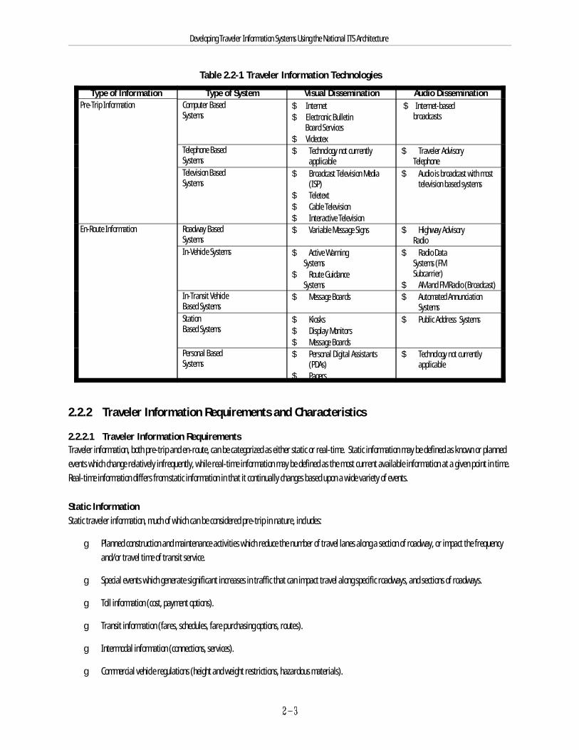
2.2.1.3 Traveler Information TechnologiesMost traveler information is collected by surveillance equipment (vehicle detectors, cameras, automated vehicle location systems), and is processed bycomputers in a transportation management center for distribution using audio and visual technologies. These technologies can be based in the home,office, passenger vehicle, transit vehicle, public transit station, or in the case of personal communication devices, can travel with a person. Thesetechnologies are summarized in Table 2.2-1.
Descriptions of these technologies are included in Appendix E, and a short discussion of applicable communication alternatives is included in Appendix F. In addition, the National ITS Architecture team conducted an in-depth survey of communications technologies—this survey is included in the Communications Analysis document of the National ITS Architecture.
Developing Traveler Information Systems Using the National ITS Architecture
Table 2.2-1. Traveler Information Technologies
Type of Information Type of System Visual Dissemination Audio DisseminationPre-Trip Information Computer Based
Systems$ Internet $ Internet-based$ Electronic Bulletin Board Services$ Videotex
broadcasts
Telephone BasedSystems
$ Technology not currently $ Traveler Advisoryapplicable Telephone
Television BasedSystems
$ Broadcast Television Media $ Audio is broadcast with most(ISP) television based systems
$ Teletext$ Cable Television$ Interactive Television
En-Route Information Roadway BasedSystems
$ Variable Message Signs $ Highway Advisory Radio
In-Vehicle Systems $ Active Warning $ Radio Data Systems Systems (FM$ Route Guidance Systems $ AM and FM Radio (Broadcast)
Subcarrier)
In-Transit VehicleBased Systems
$ Message Boards $ Automated AnnunciationSystems
StationBased Systems
$ Kiosks $ Public Address Systems$ Display Monitors$ Message Boards
Personal BasedSystems
$ Personal Digital Assistants $ Technology not currently(PDAs) applicable
$ Pagers
2.2.2 Traveler Information Requirements and Characteristics
2.2.2.1 Traveler Information RequirementsTraveler information, both pre-trip and en-route, can be categorized as either static or real-time. Static information may be defined as known or plannedevents which change relatively infrequently, while real-time information may be defined as the most current available information at a given point in time. Real-time information differs from static information in that it continually changes based upon a wide variety of events.
Static InformationStatic traveler information, much of which can be considered pre-trip in nature, includes:
g Planned construction and maintenance activities which reduce the number of travel lanes along a section of roadway, or impact the frequencyand/or travel time of transit service.
g Special events which generate significant increases in traffic that can impact travel along specific roadways, and sections of roadways.
g Toll information (cost, payment options).
g Transit information (fares, schedules, fare purchasing options, routes).
g Intermodal information (connections, services).
g Commercial vehicle regulations (height and weight restrictions, hazardous materials).
Developing Traveler Information Systems Using the National ITS Architecture
g Parking information (locations, cost).
g Yellow Pages information (services, tourist attractions, lodging, food, etc. available at destination).
g Directions to destination.
Real-time InformationReal-time information can be distributed both pre-trip and en-route. As an example, incident information is just as important to travelers who routinelycheck current conditions along their normal commuting route, prior to starting their trip, as it is to motorists currently traveling along the route where theincident has occurred. Real-time traveler information desired by travelers include:
g Roadway travel conditions associated with travel delay, such as congestion, locations of queues, and incident locations.
g Potential alternate routes which can facilitate travel, particularly in the event of a temporary roadway or transit line closure.
g Weather advisories detailing snow, ice, and fog which can impact travel.
g Transit schedule adherence.
g Park-and-ride and parking lot status (space available/not available).
g Anticipated travel time to destination (accounting for real-time conditions).
g Identification of the next stop on a train or bus.
2.2.2.2 Traveler Information CharacteristicsInterviews with operators and users of traveler information systems have been used to define the following important characteristics of travel information:
g Timely, Accurate, and Available. For travel information to be useful, it needs to be current and received in time to allow a user to acton it (e.g., route, mode, time). Travelers also want and need to know that the travel information is correct, whether it concerns the arrival timeof the next train or the location and severity of traffic problems. Finally, potential users want information to be available when needed, and beconsistent in quality (as measured by its accuracy, timeliness, and relevance to travelers’ trip needs).
g Cost Effective. Consumers will pay for timely and accurate traveler information (and associated products and services) which is relevant,helps save time, and is provided at a reasonable cost.
g Provides Route and Decision Guidance. Traveler information must contain sufficient detail – about locations, times, andpossible alternates – to be useful in planning travel, or to allow en-route adjustment of plans.
g Easy to Access and Easy to Use. Traveler information should be accessible in a variety of forms and locations – in-vehicle, personaldevices, kiosks, home computer — and be easy to use, since users perceive access time as an additional cost associated with using travelerinformation.
g Safety Implications. The extent to which traveler information can help users to avoid a dangerous situation, or to feel protected in theevent of a bad accident or other emergency, is very important. Another safety consideration is the degree to which accessing in-vehicleinformation may cause a distraction for the driver.
2.2.3 Public-Private Partnerships
TheBusiness
Public Sector Investment
Private Sector Investment
Products &Services
Revenues
Consumer
Market
Consumer Market Issues•Is the market National?•How much product/service can I sell?•Is the market large enough to attract advertisers?•What are consumers’ needs for data accuracy?•Consumer willingness to pay?
Expectations•Profitability•Return on investment•Application of products and service to new market
Expectations•Public Good•Open Markets•Cost Savings•Social Equity•ITS Goals
Developing Traveler Information Systems Using the National ITS Architecture
An extremely important issue in defining and developing traveler information systems is that of public-private partnerships, and the respective roles ofpublic agencies and private firms in implementing, operating, and maintaining these systems. While a major thrust of ITS is to stimulate thesepartnerships, the nature of public-private partnerships is still evolving. This excerpt from Shared Resources: Sharing Right-of-Way for Telecommunicationsoffers the following:
Public-private partnership agreements define how the project will be set up and includes choices related to the form ofproperty right, exclusivity, geographic scope, social issues, and procurement considerations.
General agreement between public and private partners may take the form of a legal written document or memorandum of understanding, stating howpartners will cooperate to deliver products, services and information to the public.
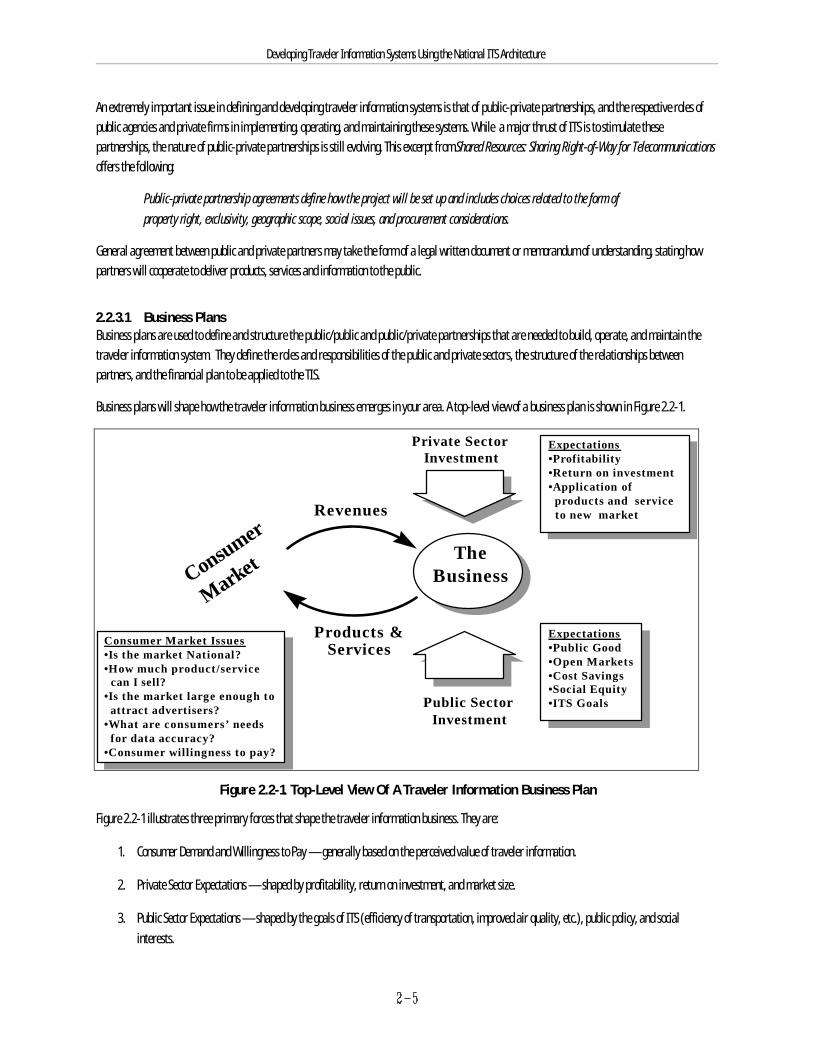
2.2.3.1 Business PlansBusiness plans are used to define and structure the public/public and public/private partnerships that are needed to build, operate, and maintain thetraveler information system. They define the roles and responsibilities of the public and private sectors, the structure of the relationships betweenpartners, and the financial plan to be applied to the TIS.
Business plans will shape how the traveler information business emerges in your area. A top-level view of a business plan is shown in Figure 2.2-1.
Figure 2.2-1. Top-Level View Of A Traveler Information Business Plan
Figure 2.2-1 illustrates three primary forces that shape the traveler information business. They are:
1. Consumer Demand and Willingness to Pay — generally based on the perceived value of traveler information.
2. Private Sector Expectations — shaped by profitability, return on investment, and market size.
3. Public Sector Expectations — shaped by the goals of ITS (efficiency of transportation, improved air quality, etc.), public policy, and socialinterests.
Developing Traveler Information Systems Using the National ITS Architecture
Technology also plays an important role in defining what products and services can be delivered in the market place. To date, significant investment infield equipment, algorithms, map technology, in-vehicle devices, personal information devices, and communications have placed traveler informationsystems on the brink of popular demand. In addition, field operational tests sponsored by the U.S. DOT have helped to establish an environment wheretechnologies can be tested and refined.
2.2.3.2 Consumer Market And Willingness To PayThis element of the business model covers the consumption side both in terms of potential consumer products and the demand for traveler informationitself. For the purposes of this discussion, we will focus on three areas (or consumer market segments).
g Commercial Traffic Reporting Agencies
g Autonomous and Advisory Traveler Information Systems
g Subscription or Fee based Traveler Information Services
A brief discussion of each follows.
Commercial Traffic Reporting FirmsCurrently, the most visible and perhaps mature form of traveler information are traffic and transit reports broadcast over radio and television. Most radiostations, and increasingly television stations in metropolitan areas, provide transit and roadway incident and congestion information, especially duringmorning and afternoon rush hours. This information is generally provided to radio and television stations as a service by commercial traffic (includingtransit) reporting firms. These firms gather roadway information from aircraft or video cameras, incidents and planned roadway construction fromtransportation agencies, and current roadway conditions from drivers with cellular telephones.
These firms are able to accumulate airtime on stations across the country and can provide a national network of advertising media to large sponsors. Thishas proven to be financially successful endeavors in many geographic markets. But, it is interesting to note that this successful business has not yet tappedinto direct-pay consumers. As is true with much of the media business, success is based on an entertaining presentation of the content and advertising.(Excerpt from Generating Revenue in the Traveler Information Marketplace, Wollenberg, S., Presentation at 1996 World Congress on IntelligentTransportation Systems.)
Autonomous and Advisory Traveler Information SystemsThe market for navigation and guidance travel information systems is growing. Indicators of this are sales figures and sales projections (market forecasts)for in-vehicle based devices. A recent study (Frost & Sullivan) indicates the rate of growth in this segment. The study researched two aspects of navigationand guidance systems—autonomous and advisory systems. Autonomous systems are defined as fully independent units, while advisory systems providethe capability of dynamic travel information content (e.g. traffic congestion, incidents, etc.).
The study states:
The potential market for these products include private automobiles, recreational vehicles, emergency service vehicles,and rental cars. The approximately 122 million privately owned cars in the United States represent an enormouspotential market.
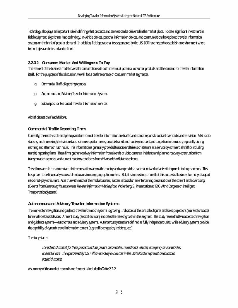
A summary of this market research and forecast is included in Table 2.2-2.

Developing Traveler Information Systems Using the National ITS Architecture
Developing Traveler Information Systems Using the National ITS Architecture
Table 2.2-2. Market Forecast for Autonomous and Advisory
Navigation and Guidance Systems
Year Autonomous Systems Advisory Systems (Units) (Units)
1994 1,000 2701995 2,800 3601996 7,700 5501997 19,700 8801998 42,700 1,9001999 84,200 4,8002000 148,800 15,1002001 216,100 47,700
Subscription or Fee-Based Traveler Information ServicesThis market remains largely untapped. However, a growing body of market research indicates a potentially bright future.
A recent Harris Research Group survey (in the New York metropolitan area) indicates that almost one-third (31%) of those surveyed said that travelerinformation would have an effect on how often they travel on certain forms of transportation. (Indications in your region may vary.) A 78% majority ofpeople surveyed during this Harris effort said they would be willing to pay something to access an improved traveler information system.
Specific results are summarized in Table 2.2-3.
Table 2.2-3. Consumer Willingness to Pay - Survey Results
Percent Willing to Pay56% $5/month40% $10/month30% $15/month44% $1 per telephone call to obtain travel information64% 50 cents per telephone call to obtain travel information
Source: TRANSCORE, Inc.
2.2.3.3 Public and Private Sector ExpectationsThe public and private sectors generally have differing points of views and consequently differing expectations with regard to traveler information systems. A potential hindrance to a successful partnership agreement is the stark difference in the way the public and private partners do business. Thesedifferences are due largely to the different measures of success used by the two sectors. This will likely impact the way partners want evaluations to beconducted, and how success of the venture is ultimately measured.
Private Sector ExpectationsThe private sector’s biggest indicator of success is profitability, with volume (number of units sold), price and quality of its products and services being keydeterminants. Vendors want a national market where the same product works anywhere in the country and are concerned about the potential size of thetraveler information systems market. Companies involved in traveler information systems today understand that their investments may give them asignificant advantage in both product development and market research, leading to earlier production of a marketable product and increased marketshare of sales to the general public ( IVHS Institutional Issues and Case Studies, FHWA, 1994). Consequently there is a desire on the part of early investorsto safeguard their investment by protecting (not sharing) the market and information with potential competitors.
Developing Traveler Information Systems Using the National ITS Architecture
Public Sector ExpectationsThe public sector’s indicators of success are generally the same as those for ITS on a national level—reducing congestion, improving driving safety, etc. Other considerations for the public sector may include: revenue generation, cost savings, motivating private investment, and open markets.
Universities (whether public or private) participate in public-private partnerships. They pride themselves on advancement of science,technology and engineering, the reputation of their professors and the quality of the students they attract and matriculate.
Roles and ResponsibilitiesThe traditional roles of the public and private sectors will continue to shape their future roles in traveler information systems ventures. For example, thepublic side will likely continue to install and operate variable message signs, and roadway sensors, while the private side will continue to provideinformation through broadcast media including radio and television. Nonetheless, many opportunities for partnering exist. These are depicted in Figure2.2-2.
Additional public sector roles may include:
g Providing static information (construction event notices and transit schedules)
g Providing seed money for infrastructure and integration
g Sharing risks and funding
Additional private sector roles may include supplementing basic information provided by public agencies, product development, and market research.
g Coordination of wireless communications (sub-carrier) leases
g Providing staff to support Traveler Information Center operations
g Sharing risks and funding

Private• Route Guidance• Yellow Pages / Reservations• Broadcast Media-based Traveler InformationPublic-Private
Partnering• Vehicle Probes• Interactive Traveler• Video Surveillance• Kiosks• Traveler Information Operations• Internet / Home & Office PC• Advisory TelephonePublic
• Transit Platform & In-vehicle Systems• Intermodal• Traffic Control• VMS/HAR• Ridesharing• Roadside Sensors
Developing Traveler Information Systems Using the National ITS Architecture
Figure 2.2-2. Public and Private Sector Roles
Developing Traveler Information Systems Using the National ITS Architecture
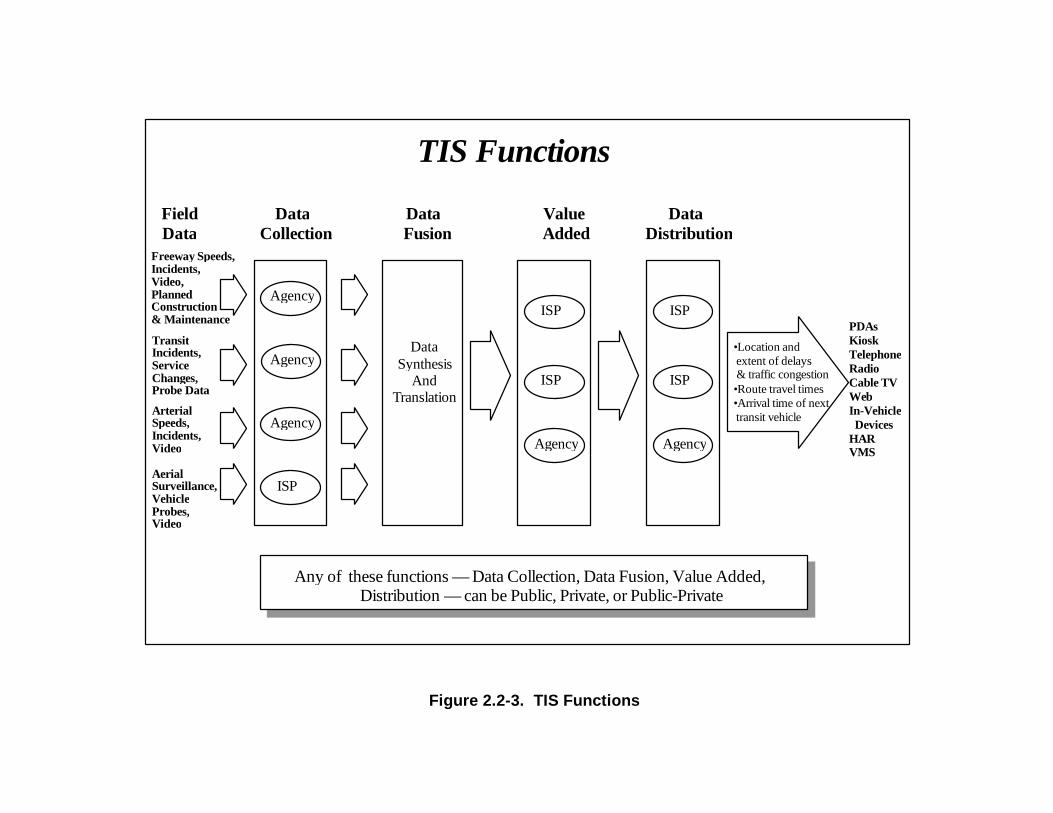
2.2.3.4 Business Plan Partnership StructureAs stated previously, a business plan outlines the structure of the relationship between partners. Figure 2.2-3 shows a detailed view of a business plan. Itis comprised of four functions—data collection, data fusion, value added, and data distribution—any of which can be provided by public, private, orpublic-private partnering.
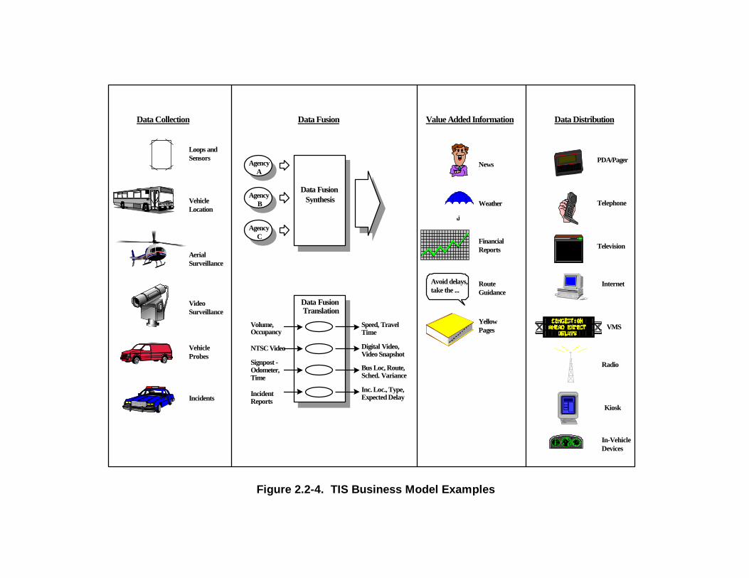
Data CollectionData collection has traditionally been managed by the public sector. This has evolved from infrastructure put in place as part of a traffic or transitmanagement system and includes: roadway traffic sensors, vehicle tags and beacons, and video surveillance cameras. However, the private sector oftensupplements the data provided by public agencies to provide complete coverage of the region. In addition, commercial traffic reporting agencies (and somepublic sector agencies) have used aerial surveillance to monitor roadway conditions. Examples of data collected and devices are shown in Figure 2.2-3 andFigure 2.2-4.
Data Fusion
Data fusion refers to two processes: data synthesis and data translation. This is shown graphically in Figure 2.2-4. Data synthesis is the combining of datafrom multiple sources, typically different agencies, into one source for subsequent distribution. Data translation includes the computer algorithms requiredto transform one or more pieces of information into another piece of information. This may include the translation of:
g Volume and occupancy into speed and travel time
g NTSC video signal from cameras into a digital format or video snapshot
g Signpost and odometer readings from buses into bus location (longitude latitude), location on route, and schedule variance (time and distance)
g Incident reports from various sources into incident location, type, and expected delay (duration)
Value-Added FunctionThe value added function includes any form of repackaging of information into a form that can be provided to consumers. This role is one typicallyperformed by the private sector (e.g. commercial traffic reporting agency), but includes any repackaging of content delivered by public agencies tomotorists—for example, using variable message signs and highway advisory radio.
Private sector value added content may include confirmation of traffic and incident reports from the public sector, and the creation of 20 second radiomessages. As previously discussed, private companies may provide additional surveillance (air, vehicle probes, CCTV video) to supplement basicinformation provided by agencies to provide total coverage of an area.
Radio and television stations bundle the transportation information provided by private firms, along with weather information, financial reports, andnews, as a value-added service to their main programming. This concept is shown in Figure 2.2-4.
Agency
DataCollection
DataFusion
DataSynthesis
AndTranslation
TIS Functions
DataDistribution
ValueAdded
FieldData
Freeway Speeds,Incidents,
ArterialSpeeds,Incidents,Video
TransitIncidents,ServiceChanges,Probe Data
PDAsKioskTelephoneRadioCable TVWebIn-Vehicle DevicesHARVMS
Any of these functions — Data Collection, Data Fusion, Value Added,Distribution — can be Public, Private, or Public-Private
AerialSurveillance,VehicleProbes,Video
Agency
Agency
ISP
ISP
ISP
Agency
ISP
ISP
Agency
•Location and extent of delays & traffic congestion•Route travel times•Arrival time of next transit vehicle
Video,PlannedConstruction& Maintenance
Figure 2.2-3. TIS Functions
Vehicle Location
Incidents
Loops and Sensors
Aerial Surveillance
VideoSurveillance
VehicleProbes
AgencyA
Agency B
Agency C
Data Fusion Synthesis
Data Fusion Translation
Volume, Occupancy
NTSC Video
Signpost - Odometer, Time
IncidentReports
Speed, TravelTime
Digital Video,Video Snapshot
Bus Loc, Route,Sched. Variance
Inc. Loc., Type,Expected Delay
Weather
FinancialReports
News
RouteGuidance
Yellow Pages
PDA/Pager
Kiosk
Telephone
Radio
Television
Internet
In-VehicleDevices
VMS
Value Added Information
Avoid delays, take the ...
Data DistributionData Collection Data Fusion
Figure 2.2-4. TIS Business Model Examples

Developing Traveler Information Systems Using the National ITS Architecture
Developing Traveler Information Systems Using the National ITS Architecture
Additional traveler information may also be provided in the form of alternate route information (route guidance), and yellow pages and reservationfunctions.
Other resources which may be contributed by a private sector partner include: office space, computers and equipment, operations and maintenance staff,software development, research (market, technology), and products.
Data Distribution
Finally, data is distributed to the consumer through a number of communications media and devices, ranging from hand held and in-vehicle devices to theInternet and commercial radio broadcast. Data content can be tailored to fit the needs of the consumer as market niches develop for specific types anddelivery mechanisms of traveler information. Traveler information technologies are discussed in Appendix E, and communications technologies arediscussed in Appendix F.
2.2.3.5 Institutional / Legal Issues
A number of institutional and legal issues may impact partnership agreements. This includes:
g Length of Partnership Agreement
g Guarantee of Information Delivery
g Compensation for Information
These are discussed below.
Length of Partnership AgreementThe length of the partnership agreement may vary and depends on two key drivers:
g How much time will the public sector subsidize and support efforts while a self-sustaining traveler information market develops?
g How much time will the private partners support efforts while a profitable traveler information market develops?
Guarantee of Information DeliveryAs previously shown in the discussion on TIS business models, delivery of information to consumers depends on the commitment to deliver informationbetween the data collection processes (generally managed by the public sector), the data fusion process (which may be managed by either public or privatesector), and the value added function and data distribution (generally managed by the private sector). Two issues must be considered: guarantee oftimeliness and frequency of delivery of information, and guarantee of information accuracy.
In addition, issues such as the need to correct problems within a certain amount of time to provide continuous and reliable information services toconsumers need to be addressed.
Compensation for InformationIn essence, the extent to which public agencies can receive compensation depends on whether their authorizing legislation defines them as highway serviceproviders or revenue generators.
Special purpose transportation agencies such as turnpike and transit agencies have the least constraining legislation, which allows considerable latitude inaccepting any type of compensation available and using such compensation for the agency’s transportation purposes.

Developing Traveler Information Systems Using the National ITS Architecture
State DOTs are highway service providers and are generally more limited in their authority to receive compensation. In some cases, states have elected toavoid negotiating for cash compensation rather than debate their authority to receive such revenues. In-kind services are often used instead of cashpayment in order to avoid the problems some agencies have receiving cash payments. (Shared Resources: Sharing Right-Of-Way for Telecommunications -Final Report, US DOT, 1996).
These issues have shaped many agencies’ policies on public information and associated compensation.
2.3 Development of Traveler Information ProjectsTransportation agencies go through a variety of steps and processes in developing and deploying transportation improvement projects. The nature andlevel of formality of these processes depends on the scope of the project, state and local procedures, funding requirements, and legislative requirements,among other things. For traveler information related projects, establishing agreements between public agencies and private sector companies may alsoaffect the project development process. However, there are certain fundamental steps that are fairly common across these processes. These basic stepsinclude:
1) Identification of transportation needs or problems
2) Identification of potential solutions to the problem
3) Planning and design of solutions to the problem
4) Funding, procurement, and implementation of the solution to the problem
Each step of this development process is briefly described below as it relates to transportation issues that agencies or public works departments involvedwith traveler information provision may experience. In some cases, traveler information should be thought of as a complementary enhancement to othersolutions, and not as a stand-alone solution to transportation problems.
2.3.1 Identification of Needs or ProblemsTypically the first step an agency takes in developing and implementing a project is the identification of existing transportation needs, objectives, orproblems. These may be identified through a number of activities, whether through a traditional transportation planning process, public questionnaire, aproblems/needs identification study, or an ITS Early Deployment Planning (EDP) process. For example, an agency may identify a particular section ofroadway that has frequent delays due to traffic volumes and an unusually high rate of incidents.
2.3.2 Identification of SolutionsBased on the identified problem, in this example delays on a section of roadway with high traffic volumes and a high occurrence of incidents, the agencywill identify potential solutions to the problem. Potential solutions to this particular problem may include some combination of:
g Implementing a system of Variable Message Signs to warn travelers of incidents and delays
g Establishing a direct connection with local traffic information service providers to provide them with up-to-the-minute status information oncurrent incidents and traffic delays
g Establishing more service patrols for quicker incident response
Developing Traveler Information Systems Using the National ITS Architecture
g Implementing CCTVs at key locations for quicker, more accurate detection, verification, and response to incidents
g Developing and implementing a cellular call-in solution
When evaluating the potential solutions, it is important to keep in mind institutional considerations and implications for operations and maintenance.
2.3.3 Planning and Design of the SolutionOnce an optimal solution to the problem has been identified, the agency typically begins a process of planning and designing the solution or system. Theplanning phase may include activities such as determining implementation and phasing strategies, and identifying and securing of funding sources. Thedesign phase may include activities such as preparing detailed specifications (for hardware, software and communications) and designing systemsconfigurations.
2.3.4 Funding, Procurement and ImplementationOnce the agency has identified the most feasible solution to the transportation challenge, the system or portion of a system is procured. The traditionalapproach to procurement is a two-step process: (1) the letting and completion of a contract to retain architect/engineering services to prepare detaileddesign specifications for the facility and (2) the letting and completion of a separate contract for the construction of the project. Due to the rapidlychanging and technological nature of ITS, the system manager approach to procurement can also be used. In this case, the system manager performs thedesign and writes the specifications. The hardware and construction is bid in the conventional manner, but the system manager remains to develop thesoftware, integrate all the different components, and provide documentation and training for the operating personnel. See Section 4 for a discussion ofthese and other procurement alternatives.
A successful process will result in the desired objectives ( which respond to the problems and needs that are identified in the first step) being satisfied bythe implemented system. Successful operations of the system (often overlooked during the project development process) over a sustained period of time isthe true indicator of how well the overall process worked.
2.4 Key Concepts of the National ITS ArchitectureThe National ITS Architecture is available as a resource for any region and will continue to be maintained by the U.S. DOT independently of any specificsystem design or region in the nation. It represents the work and collective thinking of a broad cross-section of the ITS community (systems engineers,transportation practitioners, technology specialists, system developers, consultants, etc.) over several years. As such, the National ITS Architecture containsmaterial that will assist agencies at each step of project development (which will be presented next in Section 2.5) and in thinking about how an individualproject, such as a traveler information project, fits into a larger regional transportation management context (to be discussed further in Section 3).
Because of the extensive geographic and functional scope of the National ITS Architecture and the requirements which drove its development, it isstructured somewhat differently and uses different terminology than is typically used today in the transportation community. It was developed to supportITS implementations over a 20-year time period in urban, interurban, and rural environments across the country. Accordingly, general names were givento the physical transportation system components and locations in order to accommodate a variety of local design choices and changes in technology orinstitutional arrangements over time. This allows the general structure of the National ITS Architecture to remain stable while still allowing flexibility andtailoring at the local implementation level. This difference in language can be easily overcome with a better understanding of how the National ITSArchitecture is organized and how it relates to familiar systems of today.
As background, this section explains the essential terminology and concepts needed to understand, navigate, and use the National ITS Architecture andthen provides a summary of the key documents produced under the National ITS Architecture development effort which will be referred to in the next
Developing Traveler Information Systems Using the National ITS Architecture
section. The portions of the material which are particularly relevant to traveler information systems are also highlighted. The reader who is alreadyfamiliar with the National ITS Architecture may wish to skip ahead to the next section for information on how to use this information and methodology inthe context of project development. The following concepts and terms are explained in this section:
g User Services and User Service Requirements (2.4.1)
g Logical Architecture (2.4.2)
g Physical Architecture (2.4.3)
g Equipment Packages (2.4.4)
g Market Packages (2.4.5)
Developing Traveler Information Systems Using the National ITS Architecture
2.4.1 User Services and User Service RequirementsUser services represent what the system will do from the perspective of the user. A user might be the public or a system operator.
Table 2.4-1 presents the 30 user services which formed the basis for the National ITS Architecture development effort, grouped into seven bundles forconvenience. These user services were jointly defined by a collaborative process involving USDOT and ITS America with significant stakeholder input. Clearly, a different set could have been defined. The important point is that the concept of user services allows the process of system or project definitionto begin by thinking about what high level services will be provided to address identified problems and needs. The bolded entries in the table are mostrelevant to traveler information systems.
A number of functions are required to accomplish each user service. To reflect this, each of the user services was broken down into successively moredetailed functional statements, called user service requirements, which formed the fundamental requirements for the National ITS Architecturedevelopment effort. For example, the pre-trip travel information user service is actually defined by over 40 “functions” (the hierarchy of user servicerequirements makes it difficult to provide an exact number). In the Traceability Matrix of the National ITS Architecture documentation, the user servicerequirements can be reviewed. Many of these user service requirements can be implemented today, although some of them may be more representative offuture capabilities and should be deferred for now. User service requirements can be used as a departure point for the development of project functionalrequirements and system specifications, as will be discussed in Section 2.5.

Developing Traveler Information Systems Using the National ITS Architecture
Table 2.4-1. User Services for the National ITS Architecture
User Service Bundle User ServiceTravel and Transportation En-Route Driver InformationManagement Route Guidance
Traveler Services InformationTraffic ControlIncident ManagementEmissions Testing and MitigationHighway-Rail Intersection
Travel Demand Management Pre-Trip Travel InformationRide Matching and ReservationDemand Management and Operations
Public Transportation Operations Public Transportation ManagementEn-Route Transit InformationPersonalized Public TransitPublic Travel Security
Electronic Payment Services Electronic Payment ServicesCommercial Vehicle Operations Commercial Vehicle Electronic Clearance
Automated Roadside Safety InspectionOn-Board Safety MonitoringCommercial Vehicle Administrative ProcessesHazardous Material Incident ResponseCommercial Fleet Management
Emergency Management Emergency Notification and Personal SecurityEmergency Vehicle Management
Advanced Vehicle Control and Longitudinal Collision AvoidanceSafety Systems Lateral Collision Avoidance
Intersection Collision AvoidanceVision Enhancement for Crash AvoidanceSafety ReadinessPre-Crash Restraint DeploymentAutomated Highway Systems
Table 2.4-2 provides an illustration of user service requirements using an excerpt from the pre-trip travel information user service.
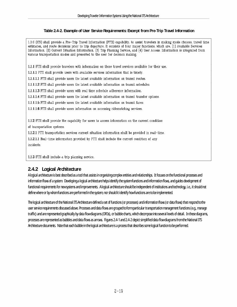
Developing Traveler Information Systems Using the National ITS Architecture
Table 2.4-2. Example of User Service Requirements: Excerpt from Pre-Trip Travel Information
2.4.2 Logical ArchitectureA logical architecture is best described as a tool that assists in organizing complex entities and relationships. It focuses on the functional processes andinformation flows of a system. Developing a logical architecture helps identify the system functions and information flows, and guides development offunctional requirements for new systems and improvements. A logical architecture should be independent of institutions and technology, i.e., it should notdefine where or by whom functions are performed in the system, nor should it identify how functions are to be implemented.
The logical architecture of the National ITS Architecture defined a set of functions (or processes) and information flows (or data flows) that respond to theuser service requirements discussed above. Processes and data flows are grouped to form particular transportation management functions (e.g., managetraffic) and are represented graphically by data flow diagrams (DFDs), or bubble charts, which decompose into several levels of detail. In these diagrams,processes are represented as bubbles and data flows as arrows. Figures 2.4-1 and 2.4-2 depict simplified data flow diagrams from the National ITSArchitecture documents. Note that each bubble in the logical architecture is a process that describes some logical function to be performed.
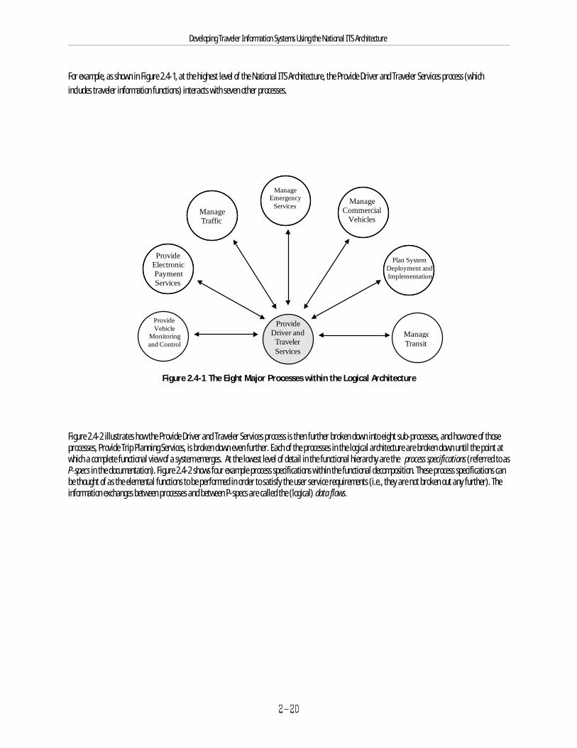
ManageTraffic
ManageEmergency
ServicesManage
CommercialVehicles
ProvideElectronicPaymentServices
Plan SystemDeployment andImplementation
ManageTransit
ProvideDriver and
TravelerServices
ProvideVehicle
Monitoringand Control
Developing Traveler Information Systems Using the National ITS Architecture
For example, as shown in Figure 2.4-1, at the highest level of the National ITS Architecture, the Provide Driver and Traveler Services process (whichincludes traveler information functions) interacts with seven other processes.
Figure 2.4-1 The Eight Major Processes within the Logical Architecture
Figure 2.4-2 illustrates how the Provide Driver and Traveler Services process is then further broken down into eight sub-processes, and how one of thoseprocesses, Provide Trip Planning Services, is broken down even further. Each of the processes in the logical architecture are broken down until the point atwhich a complete functional view of a system emerges. At the lowest level of detail in the functional hierarchy are the process specifications (referred to asP-specs in the documentation). Figure 2.4-2 shows four example process specifications within the functional decomposition. These process specifications canbe thought of as the elemental functions to be performed in order to satisfy the user service requirements (i.e., they are not broken out any further). Theinformation exchanges between processes and between P-specs are called the (logical) data flows.
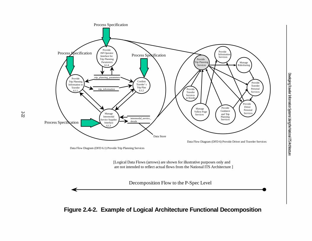
Decomposition Flow to the P-Spec Level
Data Flow Diagram (DFD 6) Provide Driver and Traveler Services
[Logical Data Flows (arrows) are shown for illustrative purposes only and are not intended to reflect actual flows from the National ITS Architecture ]
ProvideTraveler PersonalServices
ProvideDriver PersonalServices
ProvideGuidanceand TripPlanningServices
ManageYellow PageServices
ProvideTravelerServicesat Kiosks
Manage Intermodal
Service SupplierInterface
6.1.3
ConfirmTraveler’sTrip Plan
6.1.2
ProvideTrip PlanningInformation to
Traveler6.1.1
Data Flow Diagram (DFD 6.1) Provide Trip Planning Services
Process Specification
ProvideTrip Planning
Services
Figure 2.4-2. Example of Logical Architecture Functional Decomposition
ManageRidesharing
ProvideInformationServices
Provide ISP OperatorInterface for Trip Planning
Parameters6.1.4
trip_planning_parameters
trip_information
intermodal_service_details
Data Store
Process Specification
Process Specification
Process Specification
Developing Traveler Information Systems Using the National ITS Architecture
2-22
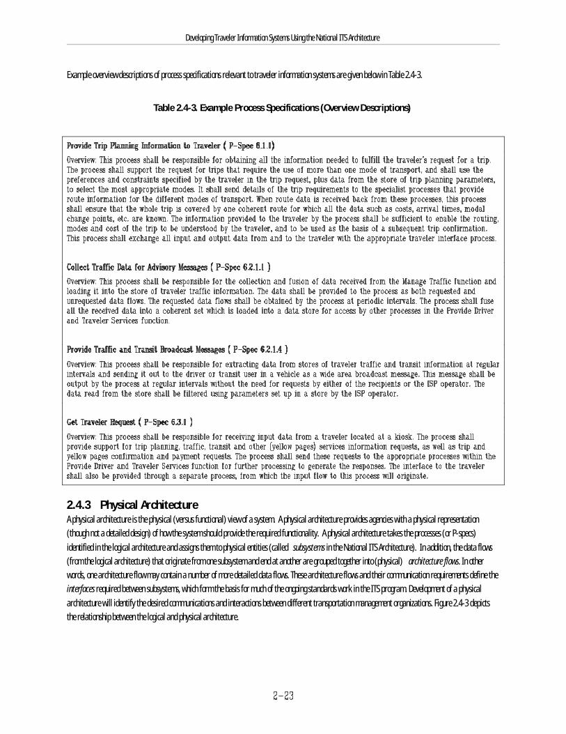
Developing Traveler Information Systems Using the National ITS Architecture
Example overview descriptions of process specifications relevant to traveler information systems are given below in Table 2.4-3.
Table 2.4-3. Example Process Specifications (Overview Descriptions)
2.4.3 Physical ArchitectureA physical architecture is the physical (versus functional) view of a system. A physical architecture provides agencies with a physical representation(though not a detailed design) of how the system should provide the required functionality. A physical architecture takes the processes (or P-specs)identified in the logical architecture and assigns them to physical entities (called subsystems in the National ITS Architecture). In addition, the data flows(from the logical architecture) that originate from one subsystem and end at another are grouped together into (physical) architecture flows. In otherwords, one architecture flow may contain a number of more detailed data flows. These architecture flows and their communication requirements define theinterfaces required between subsystems, which form the basis for much of the ongoing standards work in the ITS program. Development of a physicalarchitecture will identify the desired communications and interactions between different transportation management organizations. Figure 2.4-3 depictsthe relationship between the logical and physical architecture.

Logical Architecture -What has to be done(functions)
Physical Architecture -
(Group functionstogether)
Function A
Function B
Function C
Function D
Subsystem A Subsystem B
Dataflows
Interface
Developing Traveler Information Systems Using the National ITS Architecture
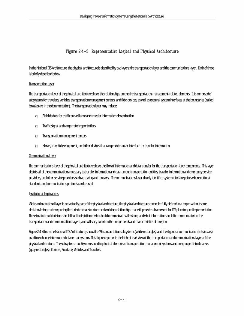
Developing Traveler Information Systems Using the National ITS Architecture
In the National ITS Architecture, the physical architecture is described by two layers: the transportation layer and the communications layer. Each of theseis briefly described below.
Transportation Layer
The transportation layer of the physical architecture shows the relationships among the transportation-management-related elements. It is composed ofsubsystems for travelers, vehicles, transportation management centers, and field devices, as well as external system interfaces at the boundaries (calledterminators in the documentation). The transportation layer may include:
g Field devices for traffic surveillance and traveler information dissemination
g Traffic signal and ramp metering controllers
g Transportation management centers
g Kiosks, in-vehicle equipment, and other devices that can provide a user interface for traveler information
Communications Layer
The communications layer of the physical architecture shows the flow of information and data transfer for the transportation layer components. This layerdepicts all of the communications necessary to transfer information and data among transportation entities, traveler information and emergency serviceproviders, and other service providers such as towing and recovery. The communications layer clearly identifies system interface points where nationalstandards and communications protocols can be used.
Institutional Implications
While an institutional layer is not actually part of the physical architecture, the physical architecture cannot be fully defined in a region without somedecisions being made regarding the jurisdictional structure and working relationships that will provide a framework for ITS planning and implementation.These institutional decisions should lead to depiction of who should communicate with whom, and what information should be communicated in thetransportation and communications layers, and will vary based on the unique needs and characteristics of a region.
Figure 2.4-4 from the National ITS Architecture, shows the 19 transportation subsystems (white rectangles) and the 4 general communication links (ovals)used to exchange information between subsystems. This figure represents the highest level view of the transportation and communications layers of thephysical architecture. The subsystems roughly correspond to physical elements of transportation management systems and are grouped into 4 classes(gray rectangles): Centers, Roadside, Vehicles and Travelers.
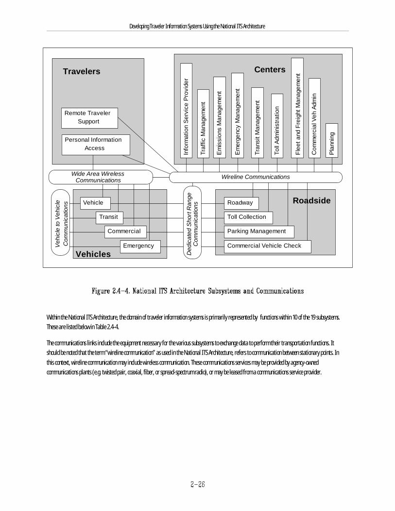
Travelers
Remote TravelerSupport
Vehicle Roadway
Toll Collection
Parking Management
Commercial Vehicle Check
Transit
Commercial
EmergencyVehicles
Roadside
Centers
Em
issi
ons
Man
agem
ent
Traf
fic M
anag
emen
t
Em
erge
ncy
Man
agem
ent
Tran
sit M
anag
emen
t
Toll
Adm
inis
tratio
n
Flee
t and
Fre
ight
Man
agem
ent
Com
mer
cial
Veh
Adm
in
Info
rmat
ion
Ser
vice
Pro
vide
r
Veh
icle
to V
ehic
leC
omm
unic
atio
ns
Ded
icat
ed S
hort
Ran
geC
omm
unic
atio
ns
Personal InformationAccess
Wide Area WirelessCommunications
Pla
nnin
g
Wireline Communications
Developing Traveler Information Systems Using the National ITS Architecture
Within the National ITS Architecture, the domain of traveler information systems is primarily represented by functions within 10 of the 19 subsystems. These are listed below in Table 2.4-4.
The communications links include the equipment necessary for the various subsystems to exchange data to perform their transportation functions. Itshould be noted that the term “wireline communication” as used in the National ITS Architecture, refers to communication between stationary points. Inthis context, wireline communication may include wireless communication. These communications services may be provided by agency-ownedcommunications plants (e.g. twisted pair, coaxial, fiber, or spread-spectrum radio), or may be leased from a communications service provider.
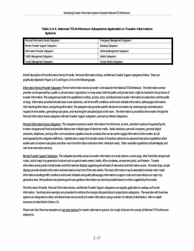
Developing Traveler Information Systems Using the National ITS Architecture
Table 2.4-4. National ITS Architecture Subsystems Applicable to Traveler Information Systems
Personal Information Access Subsystem Emergency Management Subsystem
Remote Traveler Support Subsystem Roadway Subsystem
Information Provider Subsystem Parking Management Subsystem
Traffic Management Subsystem Vehicle Subsystem
Transit Management Subsystem Transit Vehicle Subsystem
A brief description of the Information Service Provider, Personal Information Access, and Remote Traveler Support subsystems follow. These aregraphically depicted in Figure 2.4-5 and Figure 2.4-6 on the following pages.
Information Service Provider Subsystem. The term information service provider is introduced in the National ITS Architecture. The information serviceprovider can be operated by a public or private sector organization; in many areas, both the public and private sector might be involved in the provision oftraveler information. This subsystem provides the capabilities to collect, process, store, and disseminate traveler information to subscribers and the publicat large. Information provided includes basic travel advisories, real time traffic conditions and transit schedule information, yellow pages information,ride matching information, and parking information. The subsystem also provides specific directions to travelers by receiving origin and destinationrequests from travelers, generating route plans, and returning the calculated plans to the users. The information is provided to the traveler through thePersonal Information Access subsystem, Remote Traveler Support subsystem, and various Vehicle Subsystems.
Personal Information Access Subsystem. This subsystem accesses traveler information from the home, at work, and other locations frequented by thetraveler using personal fixed and portable devices over multiple types of electronic media. Radio, television, personal computers, personal digitalassistants, telephones, and any other communications-capable consumer products that can be used to supply information to the traveler are allencompassed by this subsystem definition. Sophistication ranges from simple receipt of broadcast advisories to advanced interactive capabilities whichenable users to receive route plans and other real-time information tailored to their individual needs. Other available capabilities include Mayday andreal-time reservation services.
Remote Traveler Support Subsystem. This subsystem provides access to traveler information at transit stations, transit stops, other fixed sites along travelroutes, and at major trip generation locations such as special event centers, hotels, office complexes, amusement parks, and theaters. Travelerinformation access points include kiosks and informational displays supporting varied levels of interaction and information access. At transit stops, simpledisplays provide schedule information and estimated arrival time of the next vehicle. This basic information may be extended to include multi-modalinformation including traffic conditions and transit schedules along with yellow pages information to support mode and route selection at major tripgeneration sites. Personalized route planning and route guidance information can also be provided based on criteria supplied by the traveler.
The Information Provider, Personal Information Access, and Remote Traveler Support subsystems are equally applicable to roadway and transitinformation. Two illustrative examples are presented to reinforce the concepts discussed about transportation subsystems. The examples will show howsystems are integrated to collect and disseminate various kinds of traveler information using a number of methods of distribution. More in-depthscenarios are described in Section 2.6.
Please note that these two examples are not prescriptions for traveler information systems, but simply illustrate the concept of National ITS Architecturesubsystems.
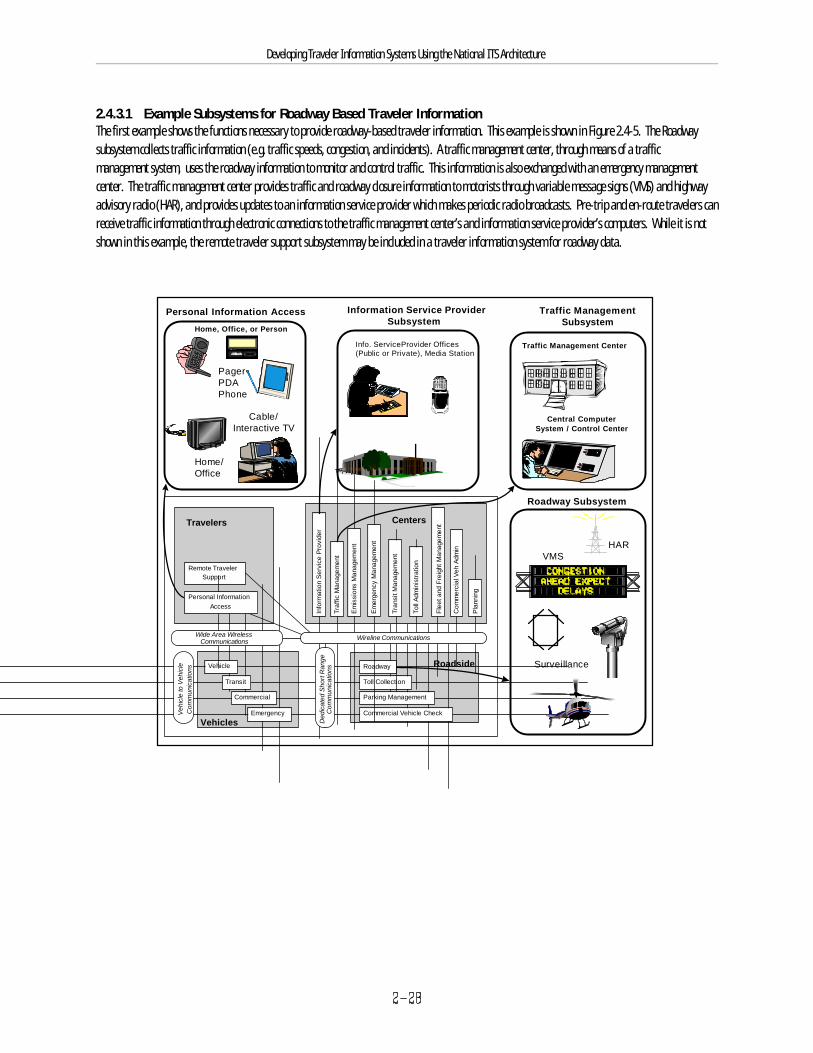
Travelers
Remote TravelerSupport
Vehicle Roadway
Toll Collection
Parking Management
Commercial Vehicle Check
Transit
Commercial
EmergencyVehicles
Roadside
Centers
Em
issi
ons
Man
agem
ent
Traf
fic M
anag
emen
t
Em
erge
ncy
Man
agem
ent
Tran
sit M
anag
emen
t
Toll
Adm
inis
tratio
n
Flee
t and
Fre
ight
Man
agem
ent
Com
mer
cial
Veh
Adm
in
Info
rmat
ion
Ser
vice
Pro
vide
r
Veh
icle
to V
ehic
leC
omm
unic
atio
ns
Ded
icat
ed S
hort
Ran
geC
omm
unic
atio
ns
Personal InformationAccess
Wide Area WirelessCommunications
Pla
nnin
g
Wireline Communications
VMS
Surveillance
Roadway Subsystem
Information Service ProviderSubsystem
Info. ServiceProvider Offices(Public or Private), Media Station
Home, Office, or Person
PagerPDAPhone
Cable/Interactive TV
Home/Office
Personal Information Access
Central ComputerSystem / Control Center
Traffic Management Center
Traffic Management Subsystem
HAR
Developing Traveler Information Systems Using the National ITS Architecture
2.4.3.1 Example Subsystems for Roadway Based Traveler InformationThe first example shows the functions necessary to provide roadway-based traveler information. This example is shown in Figure 2.4-5. The Roadwaysubsystem collects traffic information (e.g. traffic speeds, congestion, and incidents). A traffic management center, through means of a trafficmanagement system, uses the roadway information to monitor and control traffic. This information is also exchanged with an emergency managementcenter. The traffic management center provides traffic and roadway closure information to motorists through variable message signs (VMS) and highwayadvisory radio (HAR), and provides updates to an information service provider which makes periodic radio broadcasts. Pre-trip and en-route travelers canreceive traffic information through electronic connections to the traffic management center’s and information service provider’s computers. While it is notshown in this example, the remote traveler support subsystem may be included in a traveler information system for roadway data.

Developing Traveler Information Systems Using the National ITS Architecture
Figure 2.4-5. Potential Subsystems for Roadway Traveler Information Example2.4.3.2 Example Subsystems for Transit Based Traveler InformationThe second example shows the functions necessary to provide transit-based traveler information. This example, is shown in Figure 2.4-6. The example
shows the roadway subsystem which monitors the location of transit vehicles, and a transit management center which uses the information from the on-
board vehicle location system to monitor transit vehicle movements. The transit management center also controls a parking management system which
monitors parking availability at a park and ride lot. Kiosks and rider information systems at transit stations (video monitors, public address systems)
provide travelers information about transit and fare schedules, park and ride lot availability, and other trip planning information. While it is not shown in
this example, the information service provider and personal information access subsystems may be included in a traveler information system for transit
data.
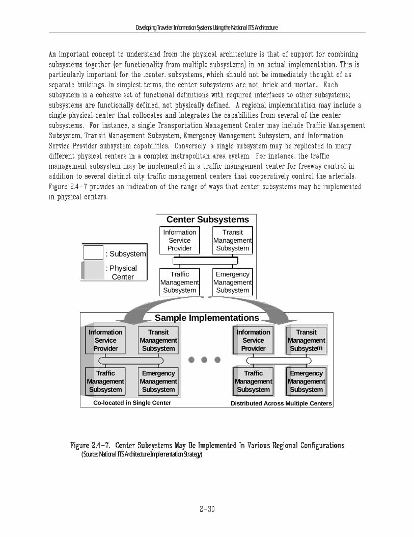
Center Subsystems
Sample Implementations
TrafficManagementSubsystem
EmergencyManagementSubsystem
TransitManagementSubsystem
InformationServiceProvider
Co-located in Single Center Distributed Across Multiple Centers
TransitManagementSubsystem
InformationServiceProvider
TrafficManagementSubsystem
EmergencyManagementSubsystem
: Physical Center
: Subsystem
TransitManagementSubsystem
InformationServiceProvider
TrafficManagementSubsystem
EmergencyManagementSubsystem
Developing Traveler Information Systems Using the National ITS Architecture
(Source: National ITS Architecture Implementation Strategy)

Developing Traveler Information Systems Using the National ITS Architecture
2.4.4 Equipment PackagesThe logical and physical architectures contain all of the essential architecture elements needed to provide the user services (and their more detailed
requirements). Although the formal definition of the National ITS Architecture stops there, other categorizations of the architecture elements were made for
the purposes of evaluation and to better understand the deployment implications. Sections 2.4.4 and 2.4.5 discuss the alternative views gained by grouping
sets of key functionality together. These perspectives, which are grounded in (or tied back to) the formal definition, can be used as additional entry points
into the National ITS Architecture.
The term “equipment package” was used in the National ITS Architecture development effort to group like functions (P-specs) of a particular subsystem
together into an “implementable” package of hardware and software capabilities (e.g., roadway infrastructure, communications, transit stop systems,
personal information devices, kiosks). The grouping of functions also took into account the user services and the need to accommodate various levels of
functionality within them. The equipment packages are associated closely with market packages (which will be discussed next) and were used as a basis
for estimating deployment costs (as part of the evaluation that was performed). The specific set of equipment packages defined is merely illustrative and
is does not represent the only way to combine the functions within a subsystem. The National ITS Architecture has defined approximately 110 equipment
packages in total. Equipment packages related to traveler information systems reside in multiple transportation subsystems of the National ITS
Architecture (see Section 2.4.3).
An example of an equipment package that is relevant to traveler information is “Basic Information Broadcast,” which is comprised of 11 process
specifications (as shown).
Basic Information Broadcast Equipment Package (part of the Information Service Provider Subsystem):
This Equipment package provides the capabilities to collect, process, store, bill, and disseminate traveler information including traveler, transit, ridematching, traffic, and parking information.The traveler information shall include maintaining a database of local area services available to travelers with up-to-the-minute information and providing an interactive connectivity between,sponsors, and providers of services. The transit information shall include the latest available information on transit routes and schedules, transit transfer options, transit fares, and real-timeschedule adherence. The traffic information shall include latest available information on traffic and highway conditions, and current situation information in real-time including incidents, roadconstruction, recommended routes, current speeds on specific routes, current parking conditions in key areas, schedules for any current or soon to start events, and current weather situations.This Equipment package shall also provide users with real-time travel related information while they are traveling, and disseminate to assist the travelers in making decisions about transfers andmodification of trips. These capabilities shall be provided using equipment such as a fixed facility with a communications system such as a data subcarrier multiplexing device.
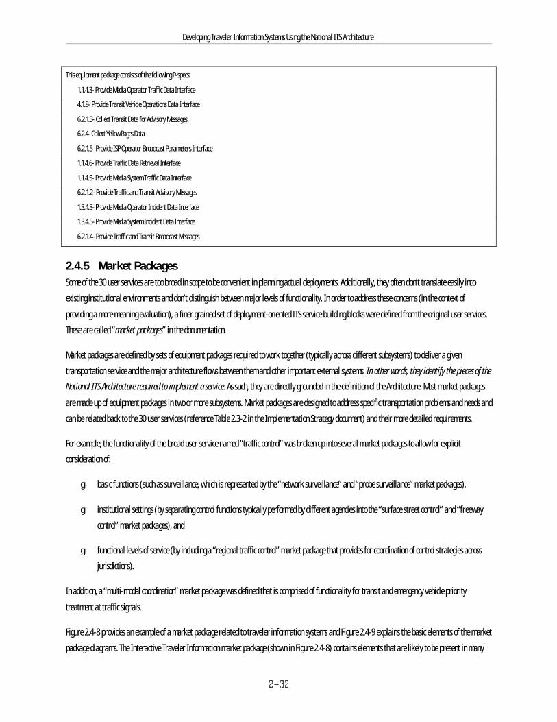
Developing Traveler Information Systems Using the National ITS Architecture
This equipment package consists of the following P-specs:
1.1.4.3- Provide Media Operator Traffic Data Interface
4.1.8- Provide Transit Vehicle Operations Data Interface
6.2.1.3- Collect Transit Data for Advisory Messages
6.2.4- Collect Yellow Pages Data
6.2.1.5- Provide ISP Operator Broadcast Parameters Interface
1.1.4.6- Provide Traffic Data Retrieval Interface
1.1.4.5- Provide Media System Traffic Data Interface
6.2.1.2- Provide Traffic and Transit Advisory Messages
1.3.4.3- Provide Media Operator Incident Data Interface
1.3.4.5- Provide Media System Incident Data Interface
6.2.1.4- Provide Traffic and Transit Broadcast Messages
2.4.5 Market PackagesSome of the 30 user services are too broad in scope to be convenient in planning actual deployments. Additionally, they often don’t translate easily into
existing institutional environments and don’t distinguish between major levels of functionality. In order to address these concerns (in the context of
providing a more meaning evaluation), a finer grained set of deployment-oriented ITS service building blocks were defined from the original user services.
These are called “market packages” in the documentation.
Market packages are defined by sets of equipment packages required to work together (typically across different subsystems) to deliver a given
transportation service and the major architecture flows between them and other important external systems. In other words, they identify the pieces of the
National ITS Architecture required to implement a service. As such, they are directly grounded in the definition of the Architecture. Most market packages
are made up of equipment packages in two or more subsystems. Market packages are designed to address specific transportation problems and needs and
can be related back to the 30 user services (reference Table 2.3-2 in the Implementation Strategy document) and their more detailed requirements.
For example, the functionality of the broad user service named “traffic control” was broken up into several market packages to allow for explicit
consideration of:
g basic functions (such as surveillance, which is represented by the “network surveillance” and “probe surveillance” market packages),
g institutional settings (by separating control functions typically performed by different agencies into the “surface street control” and “freeway
control” market packages), and
g functional levels of service (by including a “regional traffic control” market package that provides for coordination of control strategies across
jurisdictions).
In addition, a “multi-modal coordination” market package was defined that is comprised of functionality for transit and emergency vehicle priority
treatment at traffic signals.
Figure 2.4-8 provides an example of a market package related to traveler information systems and Figure 2.4-9 explains the basic elements of the market
package diagrams. The Interactive Traveler Information market package (shown in Figure 2.4-8) contains elements that are likely to be present in many
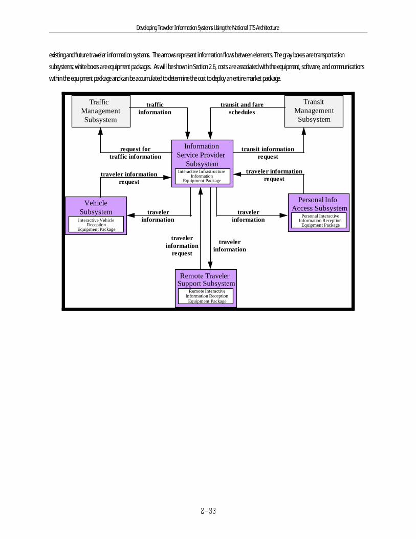
Personal InfoAccess Subsystem
Remote TravelerSupport Subsystem
VehicleSubsystem
Personal InteractiveInformation Reception
Equipment Package
Remote InteractiveInformation Reception
Equipment Package
Interactive VehicleReception
Equipment Package
travelerinformation
Traffic ManagementSubsystem
TransitManagement
Subsystem
InformationService Provider
SubsystemInteractive Infrastructure
InformationEquipment Package
trafficinformation
transit and fareschedules
request fortraffic information
transit informationrequest
travelerinformation
travelerinformation
traveler informationrequest
traveler informationrequest
travelerinformation
request
Developing Traveler Information Systems Using the National ITS Architecture
existing and future traveler information systems. The arrows represent information flows between elements. The gray boxes are transportation
subsystems; white boxes are equipment packages. As will be shown in Section 2.6, costs are associated with the equipment, software, and communications
within the equipment package and can be accumulated to determine the cost to deploy an entire market package.
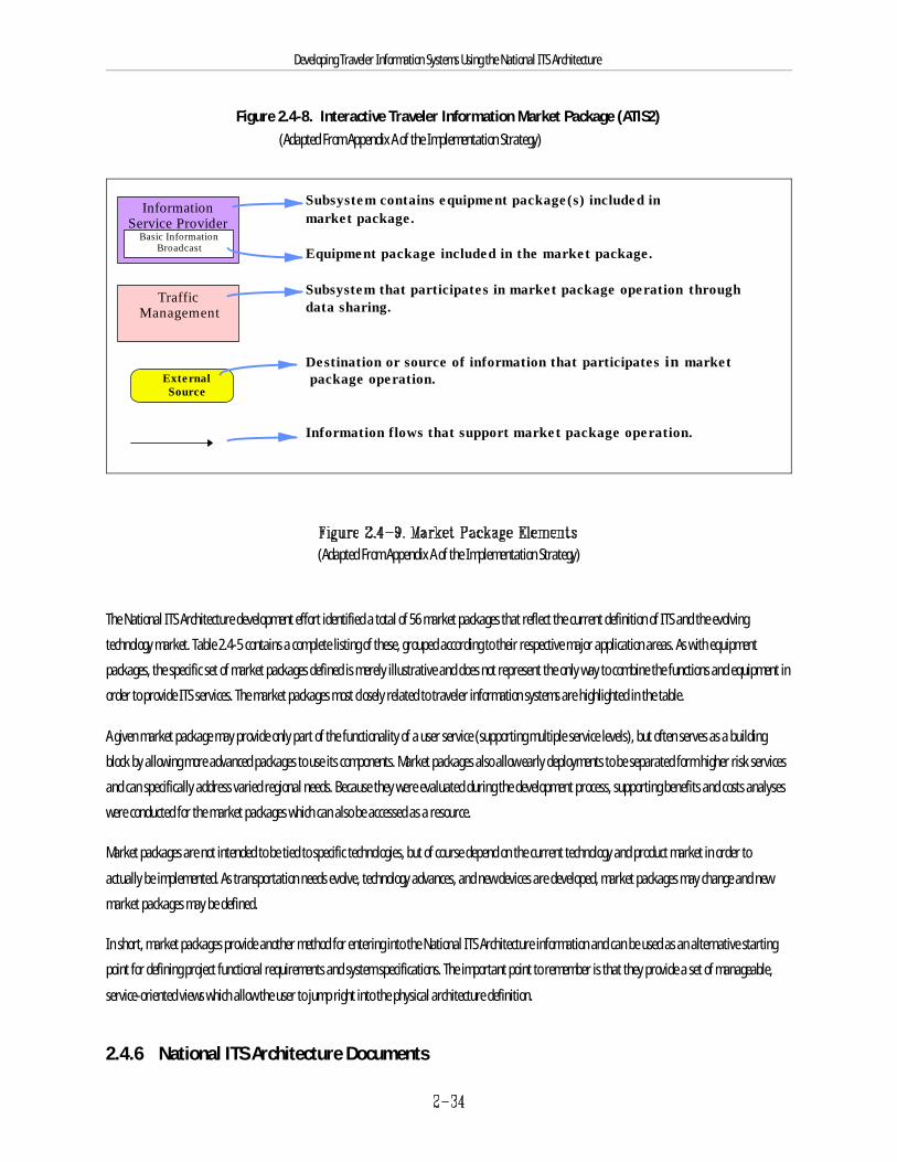
TrafficManagement
InformationService Provider
Basic InformationBroadcast
ExternalSource
Subsystem contains equipment package(s) included inmarket package.
Equipment package included in the market package.
Subsystem that participates in market package operation throughdata sharing.
Destination or source of information that participates in market package operation.
Information flows that support market package operation.
Developing Traveler Information Systems Using the National ITS Architecture
Figure 2.4-8. Interactive Traveler Information Market Package (ATIS2) (Adapted From Appendix A of the Implementation Strategy)
(Adapted From Appendix A of the Implementation Strategy)
The National ITS Architecture development effort identified a total of 56 market packages that reflect the current definition of ITS and the evolving
technology market. Table 2.4-5 contains a complete listing of these, grouped according to their respective major application areas. As with equipment
packages, the specific set of market packages defined is merely illustrative and does not represent the only way to combine the functions and equipment in
order to provide ITS services. The market packages most closely related to traveler information systems are highlighted in the table.
A given market package may provide only part of the functionality of a user service (supporting multiple service levels), but often serves as a building
block by allowing more advanced packages to use its components. Market packages also allow early deployments to be separated form higher risk services
and can specifically address varied regional needs. Because they were evaluated during the development process, supporting benefits and costs analyses
were conducted for the market packages which can also be accessed as a resource.
Market packages are not intended to be tied to specific technologies, but of course depend on the current technology and product market in order to
actually be implemented. As transportation needs evolve, technology advances, and new devices are developed, market packages may change and new
market packages may be defined.
In short, market packages provide another method for entering into the National ITS Architecture information and can be used as an alternative starting
point for defining project functional requirements and system specifications. The important point to remember is that they provide a set of manageable,
service-oriented views which allow the user to jump right into the physical architecture definition.
2.4.6 National ITS Architecture Documents

Developing Traveler Information Systems Using the National ITS Architecture
In summary, the National ITS Architecture provides a common structure for the design of ITS; it defines the functions that must be performed by
components or subsystems, where these functions reside (e.g., roadside, traffic management center, or in-vehicle), the interfaces and information flows
between subsystems, and the communications requirements for the information flows (e.g., wireline or wireless) in order to address the underlying user
service requirements. Since the National ITS Architecture is also the foundation for much of the ongoing ITS standards work, consideration of the interface
and information exchange requirements established by the Architecture today will likely facilitate or ease the transition to incorporating standards-
compliant interfaces in the future (when approved standards are available).
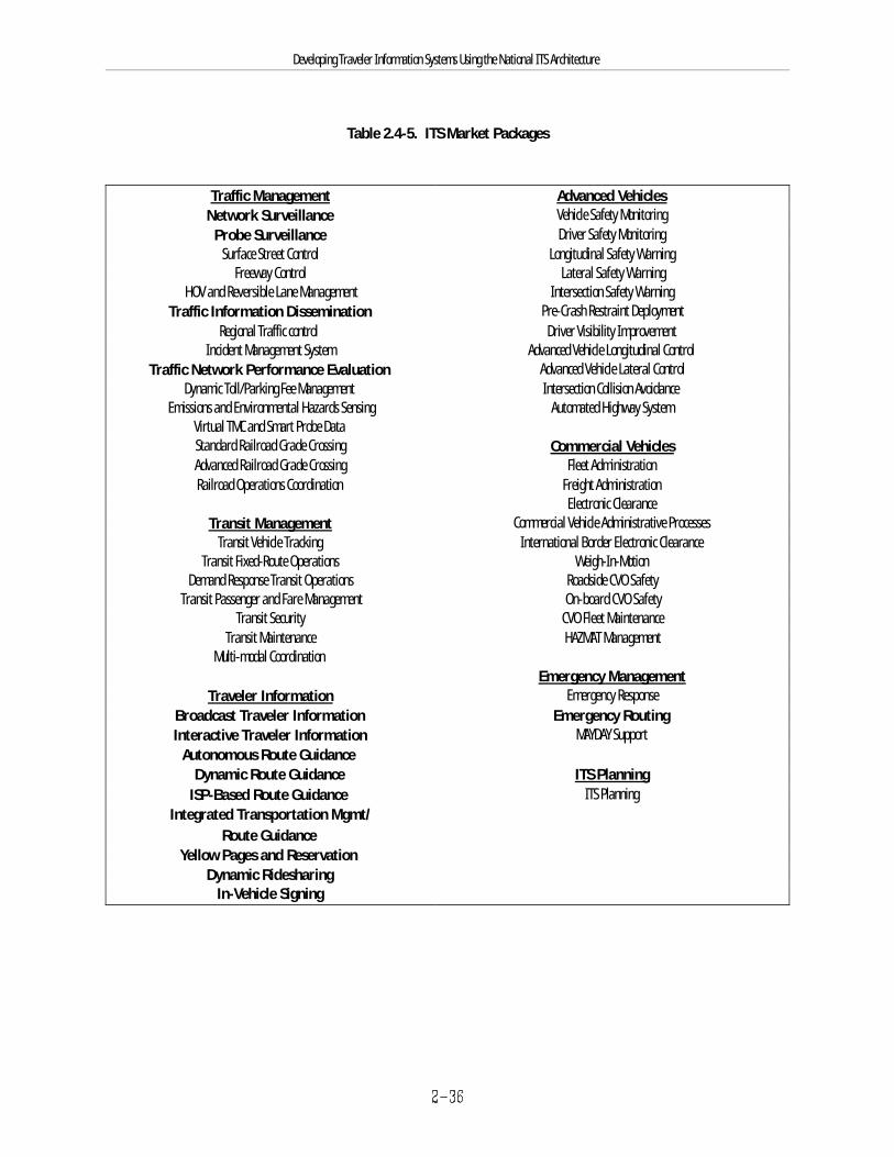
Developing Traveler Information Systems Using the National ITS Architecture
Table 2.4-5. ITS Market Packages
Traffic Management Advanced VehiclesNetwork Surveillance Vehicle Safety Monitoring
Probe Surveillance Driver Safety MonitoringSurface Street Control Longitudinal Safety Warning
Freeway Control Lateral Safety WarningHOV and Reversible Lane Management Intersection Safety Warning
Traffic Information Dissemination Pre-Crash Restraint DeploymentRegional Traffic control Driver Visibility Improvement
Incident Management System Advanced Vehicle Longitudinal ControlTraffic Network Performance Evaluation Advanced Vehicle Lateral Control
Dynamic Toll/Parking Fee Management Intersection Collision AvoidanceEmissions and Environmental Hazards Sensing Automated Highway System
Virtual TMC and Smart Probe DataStandard Railroad Grade Crossing Commercial VehiclesAdvanced Railroad Grade Crossing Fleet AdministrationRailroad Operations Coordination Freight Administration
Electronic ClearanceTransit Management Commercial Vehicle Administrative Processes
Transit Vehicle Tracking International Border Electronic ClearanceTransit Fixed-Route Operations Weigh-In-Motion
Demand Response Transit Operations Roadside CVO SafetyTransit Passenger and Fare Management On-board CVO Safety
Transit Security CVO Fleet MaintenanceTransit Maintenance HAZMAT Management
Multi-modal CoordinationEmergency Management
Traveler Information Emergency ResponseBroadcast Traveler Information Emergency RoutingInteractive Traveler Information MAYDAY Support
Autonomous Route GuidanceDynamic Route Guidance ITS Planning
ISP-Based Route Guidance ITS PlanningIntegrated Transportation Mgmt/
Route GuidanceYellow Pages and Reservation
Dynamic RidesharingIn-Vehicle Signing
Developing Traveler Information Systems Using the National ITS Architecture
The following are brief descriptions of the documents produced under the National ITS Architecture Development Program that are referred to insubsequent sections. Paper copies of these can be obtained and used as reference documents. Another way to access them is via CD-ROM or on theInternet (see Section 5.1 of this document for information on how to obtain the paper copies, the CD-ROM, and the Internet addresses). The CD-ROM andthe Internet sites will be more useful than hard copies when trying to access information rapidly. On the Internet, logical links (called “hyperlinks”)between different parts of the architecture facilitate use of information for the type of exercises described later in this section. The CD-ROM also containsthe underlying relational databases which define the Architecture (developed with Microsoft Access ), which can be useful for performing tailored searchesTM
or other advanced analyses. It is important to remember that the key concepts and elements of the National ITS Architecture as presented in Sections2.4.1-2.4.5 are interrelated and traceable in a variety of ways (forwards and backwards).
Although the documentation at first can appear to be extensive, even overwhelming, keep in mind that only a portion of the information will apply to the
specific needs of an agency at any point in time. Using the electronic tools with search capabilities and the linked HTML version of the National ITS
Architecture, finding the relevant information becomes even more manageable.
U.S. DOT plans to update and maintain the National ITS Architecture over time to reflect changing needs and correct any deficiencies that may be found
through the experience of users. Accordingly, critical portions of these documents, particularly those containing the Architecture definition, will be updated
over time (e.g., an update is currently planned for 1998). Therefore, while this document provides specific information and examples from the National ITS
Architecture (January 1997 version) for illustration purposes, the reader should always consult and defer to the latest version of the National ITS
Architecture. See Section 5 for more information on how to access the National ITS Architecture.
It is important to keep in mind that several of the documents that were produced were done so for the purposes of evaluation; these documents can be
used as additional resources (e.g., the Cost Analysis) but are peripheral to the fundamental definition. A first time interested reader should find the
Executive Summary, Vision, and Implementation Strategy to be the most accessible starting points for looking into the documentation. A complete listing of
the documents can be found in Appendix D.
VisionThe vision is the starting point for developing an architecture and is the component that drives everything else. The vision statement provides a description
of the likely transportation system in the next 5, 10, and 20 years based on the National ITS Architecture. In the vision, the ITS User Services that the
transportation system is to provide are identified in groups.
Developing Traveler Information Systems Using the National ITS Architecture
The Mission addresses the goals and objectives of a national intelligent transportation system. In the Mission, user service requirements are defined, and
benefits that the system is expected to provide are identified. The mission definition ties the National ITS Architecture to the National ITS Program Plan
developed jointly by US DOT and ITS America.
Logical Architecture The Logical Architecture document contains three volumes: Description (Volume 1), Process Specifications (Volume 2), and Data Dictionary (Volume 3).
These documents present a functional view of the ITS user services, contain diagrams that show processes and data flows among them, and define data
elements, respectively.
Physical ArchitectureThe Physical Architecture document contains architecture flow diagrams that show data passing among physical subsystems, and presents characteristics
and constraints on the data flows.
Traceability The Traceability document shows how the National ITS Architecture satisfies the user service requirements. It contains tables that provide traceability of
ITS user service requirements to National ITS Architecture elements, and traceability between logical architecture elements and physical architecture
elements.
Theory Of Operations This document provides a detailed narrative of how the architecture supports the ITS user services, described in the Mission Definition. It is a technicaldocument, intended for engineers, operators, and others involved in detailed systems design.
Communications The Communications document presents an analysis of the communications aspects of the National ITS Architecture. It presents a technology assessmentthat covers several potential communications technology alternatives. The alternatives are compared against ITS requirements. This document proposesquantitative data loading requirements for a hypothetical system design, and contains an extensive set of appendices that deal with a specificcommunications study.
Cost Analysis The Cost Analysis provides typical unit costs for market packages and equipment packages. Methodologies are delineated.
Performance and Benefits Study The Performance and Benefits Study documents the results of evaluations of several hypothetical ITS deployment scenarios. It also presents a discussion ofthe overall benefits of developing the National ITS Architecture.
Standards Requirements
Developing Traveler Information Systems Using the National ITS Architecture
The Standards Requirements document contains detailed information on requirements for 12 high-priority standards packages. Standards interfacepackages that apply to traveler information systems include:
g Digital map data exchange and location referencing
g Information Service Provider to Other Centers
g Information Service Provider Wireless Interfaces
g Traffic Management Subsystems to Other Centers
g Traffic Management Subsystems to Roadside Devices
g Dedicated Short Range Communications (DSRC)
Implementation Strategy The Implementation Strategy document presents a process for implementing ITS services in a phased approach. The process is part of an overall strategythat includes recommendations for future research and development, operational tests, standards activities, and training.
The Implementation Strategy translates the National ITS Architecture to implementation through market packages. It identifies the market packages thatprovide certain ITS services and recommends a phased deployment of those market packages to provide the most needed and most feasible user servicesinitially, and less needed/feasible user services at a later date. The Implementation Strategy considers several items and issues regarding deployment,such as legacy systems, politics, funding, market package synergy, technology requirements, and standards requirements.
2.5 Using the National ITS Architecture to Develop Traveler Information Projects This section describes the specific ways that the National ITS Architecture can be used in each of the general steps of the project development processpresented in Section 2.3, making use of the key concepts described in Section 2.4. This process addresses (1) needs or problem identification, (2) solutionidentification, (3) solution planning and design, and (4) funding, procurement, and implementation. Before discussing the specific ways it can be appliedto the project development process, some additional context and general guidance is provided below.
National ITS Architecture Application Guidance
The National ITS Architecture tools are intended to augment and support existing ITS project development processes, and should be applied withengineering judgment in that context. The National Architecture is not a process in and of itself. It contributes information and analysis to existingprocesses (e.g., systems engineering). By providing a source for critical information early in the development process, the National ITS Architecture canlower project risks and costs while also improving the potential that the resulting deployment will have long term utility and support regional ITSintegration over time.
The National ITS Architecture tools are most applicable in the early stages of project development. They fully support the rapid definition of a startingpoint for project definition, with local requirements then driving the tailoring of that project for specific applications. Of course, the tools do not contain allthe information necessary to fully design and implement ITS projects. While helpful information is sometimes available within the documentation (forexample, in the evaluation documents), specification of issues such as performance requirements, design options, technology choices, existing systeminterfaces and constraints, detailed implementation and operational decisions, and which standards to use needs to be carried out at the local level.Awareness of how far into the project development process the National ITS Architecture tools apply is important to being able to make the best use of
Developing Traveler Information Systems Using the National ITS Architecture
them.
The National ITS Architecture can be used to provide project developers with additional options to consider for information exchanges and functionality thatmay not have initially been conceived at the outset of the project. As such, its utility is likely to be greater for larger projects with a variety of possibleinterfaces. Using the National ITS Architecture should not be viewed as an all-or-nothing requirement; rather, the material can be used as is, tailored, ordropped, as appropriate for the situation. This will be discussed further in this section.
There are several ways to apply the National ITS Architecture; the most accessible of these methods will be presented in this section. See Section 5 for moreinformation on how to gain access to the various formats of the National ITS Architecture (including web sites).
Entry Points into the National ITS Architecture
The definition of the National ITS Architecture can be found in the logical and physical architectures. These architecture definitions exist in severalformats, including paper documents, Microsoft Access relational databases, and a HyperText Mark-up Language (HTML) model, which provides accessTM
through a linked model. The databases and the linked HTML model are available on CD-ROM and the World Wide Web. The logical and physicalarchitecture definitions represent a breadth and depth of information that can seem overwhelming to access and apply. However, there are tools to viewthe architecture definition that make the extraction of information more efficient. These maps and tables provide access or “entry points” to the details ofthe architecture in an organized fashion. Figure 2.5-1 shows the top-level of information shown for the linked HTML model, which provides easy access tomost of these entry points. Some of the key entry points and their relevance to project development are discussed below.
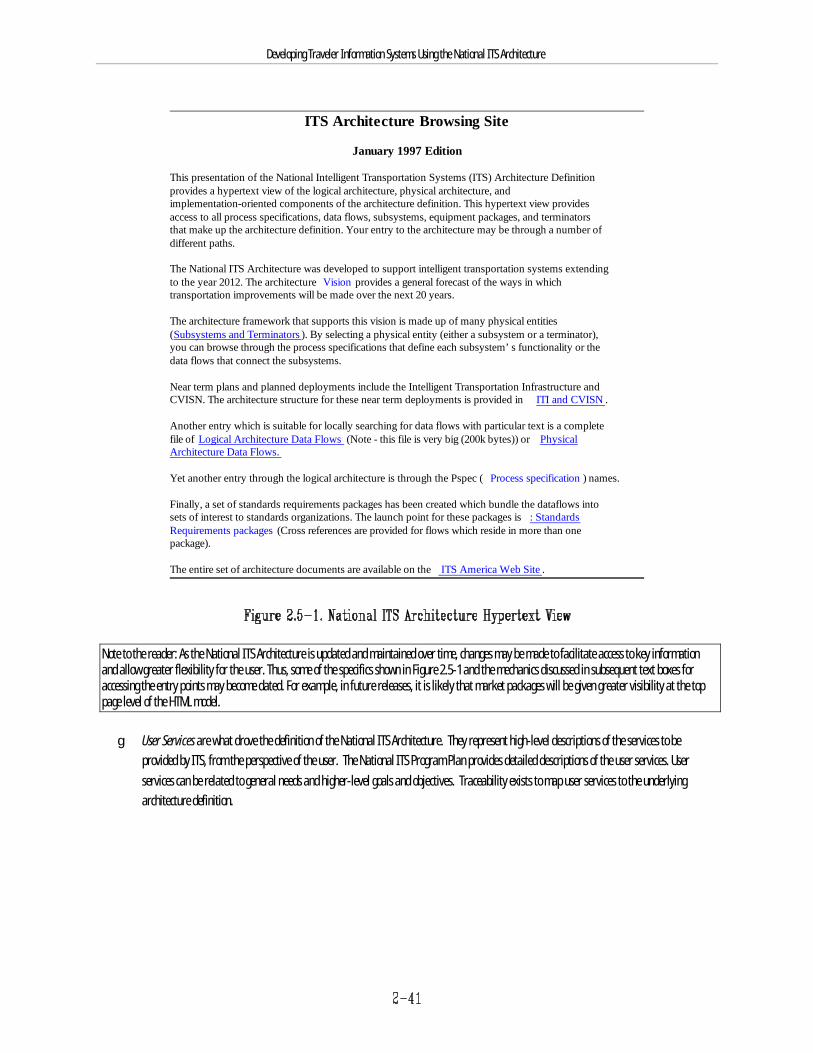
ITS Architecture Browsing Site
January 1997 Edition
This presentation of the National Intelligent Transportation Systems (ITS) Architecture Definitionprovides a hypertext view of the logical architecture, physical architecture, andimplementation-oriented components of the architecture definition. This hypertext view providesaccess to all process specifications, data flows, subsystems, equipment packages, and terminatorsthat make up the architecture definition. Your entry to the architecture may be through a number ofdifferent paths.
The National ITS Architecture was developed to support intelligent transportation systems extendingto the year 2012. The architecture Vision provides a general forecast of the ways in whichtransportation improvements will be made over the next 20 years.
The architecture framework that supports this vision is made up of many physical entities(Subsystems and Terminators ). By selecting a physical entity (either a subsystem or a terminator),you can browse through the process specifications that define each subsystem’s functionality or thedata flows that connect the subsystems.
Near term plans and planned deployments include the Intelligent Transportation Infrastructure andCVISN. The architecture structure for these near term deployments is provided in ITI and CVISN .
Another entry which is suitable for locally searching for data flows with particular text is a completefile of Logical Architecture Data Flows (Note - this file is very big (200k bytes)) or PhysicalArchitecture Data Flows.
Yet another entry through the logical architecture is through the Pspec ( Process specification ) names.
Finally, a set of standards requirements packages has been created which bundle the dataflows intosets of interest to standards organizations. The launch point for these packages is : StandardsRequirements packages (Cross references are provided for flows which reside in more than onepackage).
The entire set of architecture documents are available on the ITS America Web Site .
Developing Traveler Information Systems Using the National ITS Architecture
Note to the reader: As the National ITS Architecture is updated and maintained over time, changes may be made to facilitate access to key informationand allow greater flexibility for the user. Thus, some of the specifics shown in Figure 2.5-1 and the mechanics discussed in subsequent text boxes foraccessing the entry points may become dated. For example, in future releases, it is likely that market packages will be given greater visibility at the toppage level of the HTML model.
g User Services are what drove the definition of the National ITS Architecture. They represent high-level descriptions of the services to beprovided by ITS, from the perspective of the user. The National ITS Program Plan provides detailed descriptions of the user services. Userservices can be related to general needs and higher-level goals and objectives. Traceability exists to map user services to the underlyingarchitecture definition.
Developing Traveler Information Systems Using the National ITS Architecture
g User Service Requirements, as previously described in Section 2.4.1, are the “shall” statements that define the user services in detail and serveas the fundamental requirements of the National ITS Architecture. By selecting those user service requirements that apply to the definition ofa specific system, traces can be made to the physical and logical architectures. The user service requirements are listed in Appendix A of theTraceability document on paper or CD-ROM.
g Logical Architecture describes “what” the National ITS Architecture must do to satisfy the User Services by defining required functions anddataflows. These functions and dataflows define the lower level details of the architecture. This tool is useful when defining the functionsrequired to satisfy a service, requirement, or need. It leverages the extensive analysis already performed in the development of the NationalITS Architecture. It provides process specifications that can be tailored to fit local requirements. The logical architecture is available on paper,CDROM, and the hyperlinked HTML model.
In the HTML model, click on “hypertext view” from the top page, then “Process Specifications” (see Figure 2.5-1) in order to see a list of the p-specs,which are organized numerically according to their definition in the data flow diagram hierarchy. Or, you can click on “Logical Architecture Data Flows”in order to see the alphabetized list of logical data flows and get more information on them.
g Physical Architecture Elements are the subsystems and architecture flows that result from a partitioning of the logical architecture. Thesesubsystems and architecture flows define a higher level of the architecture and can be aligned with high-level system functions such as “trafficmanagement” or “information service provider.” In this manner, a mapping at the physical architecture subsystem level can be developedthat provides the links to the underlying logical architecture. The physical architecture is available on paper, CDROM, and the linked HTMLmodel.
In the HTML model, click on “hypertext view” from the top page, then “Subsystems and Terminators” (see Figure 2.5-1) in order to see a list of thesubsystems, which are given alphabetically. Clicking on one of the subsystems gives lots of information about the subsystem, including a description, listof equipment packages it contains, corresponding process specifications, and an architecture flow diagram. Some of these can be further explored viaadditional links. You can also click on Physical Architecture Data Flows, as shown on Figure 2.5-1.
g Market Packages, as previously described in Section 2.4.5, represent slices of the National ITS Architecture that address specific services such assurface street control. These physical architecture subsets can be selected and aggregated to form a high-level architecture at the subsystemlevel. The market packages can be traced further to equipment packages and logical architecture functions. The market package definitionsare available in the Implementation Strategy on paper and the CD-ROM, and also in the hyperlinked HTML model.
Developing Traveler Information Systems Using the National ITS Architecture
In the HTML model, click on “hypertext view” from the top page, then “ITI and CVISN” (see Figure 2.5-1) in order to see a list of the market packages,which are organized into early, additional, and advanced categories. Clicking on one of the market packages produces a wealth of information onrelevant subsystems, equipment packages, architecture flows, related market packages, and evaluation information.
g ITS Infrastructure Elements are described in US DOT’s Operation Timesaver initiative and define metropolitan, rural, and commercial vehicleinfrastructure elements that form the foundation of ITS. These elements represent high-level service categories (e.g., traffic signal controlsystems, freeway management systems, transit management systems, multi-modal traveler information systems) that are mapped into thearchitecture. This mapping provides the supporting architecture for the ITS Infrastructure in terms of the logical and physical architecture.
Using the linked HTML model, a physical architecture flow diagram will be presented when one of the ITS Infrastructure elements is clicked on (click on“hypertext view” from the top page, then “ITI and CVISN” in order to see the ITS Infrastructure elements).
By using the CD-ROM with appropriate viewing software that can read “.pdf” files (such as the Adobe Acrobat Reader), searches can be carried out on7
words of interest that might apply to a specific project or functional area. In addition, textual information can be copied (using the “select text” featureof the software) and pasted into a word processing application for further modification. Graphics information can also be downloaded (using “selectgraphics”), although it may not be as easy to modify these electronic tables or figures. Text and graphics information can always be printed and theinformation manually entered as inputs to other software programs.
2.5.1 Identification of Needs or ProblemsAs discussed in Section 2.3.1, most transportation needs and problems are identified through the planning process as part of the ongoing process ofimproving transportation systems at the local level. As such, the National ITS Architecture is unlikely to contribute much information to this initial step.However, it can assist agencies in identifying ITS goals and objectives that are specific to their needs. Both current and future needs should be identified.Goals and objectives identified in the National ITS Architecture (Mission Definition) that pertain to traveler information systems include:
g Increase operational efficiency and capacity of the transportation system$ Increase operational efficiency$ Increase speeds and reduce stops$ Reduce delays at intermodal transfer points$ Reduce operating costs of the infrastructure$ Increase private vehicle occupancy and transit usage$ Reduce private vehicle and transit operating costs$ Reduce freight operating costs and increase freight throughput
Developing Traveler Information Systems Using the National ITS Architecture
g Enhance personal mobility and the convenience and comfort of the transportation system$ Increase personal travel opportunities$ Decrease personal costs of travel including:
B Discomfort, stress, fatigue, and confusionB Safety and personal security
$ Increase sense of control over one’s own life from predictable system operation$ Decrease cost of freight movement to shippers, including:
B More reliable “just-in-time” deliveryB Reduce travel time and costB Reduce driver fatigue and stressB Safety (e.g., from tracking hazardous material)
g Improve the safety of the nation’s transportation system$ Reduce number and severity (cost) of accidents and vehicle thefts$ Reduce fatalities
g Reduce energy consumption and environmental costs$ Reduce vehicle emissions and fuel consumption due to congestion$ Reduce noise pollution$ Reduce neighborhood traffic intrusiveness
g Enhance present and future economic productivity of individuals, organizations, and the economy as a whole$ Increase sharing of incident/congestion information
The National ITS Architecture documentation includes a Vision Statement, which describes ITS capabilities now and into the future in magazine articlestyle. The Vision can also serve to foster general ideas about the types of local needs and problems that ITS can be used to address.
The National ITS Architecture also includes data collection subsystems, such as the planning subsystem, to highlight the value of using ITS to collect long-term performance data on the transportation system. Collecting and using this type of information can enhance and augment the process of identifyingneeds and problems in the future.
Useful National ITS Architecture Documents: Mission Definition, Vision Statement
2.5.2 Identification of SolutionsThere are at least two major ways that the National ITS Architecture can be applied to the identification of alternative solutions to the given needs andproblems, leading to the ultimate selection of a preferred solution. During this step, traditional solutions to the problem or combinations of traditionaland ITS strategies may also be explored.
2.5.2.1 User ServicesAs discussed in Section 2.4.1, user services and associated user service requirements were fundamental to the National ITS Architecture developmenteffort. These user services were designed to address surface transportation needs. Agencies may wish to review the list of user services in their search forpotential solutions to the given needs and problems. A list of user services and those most relevant to traveler information systems was provided in Table2.4-1.
The following is a summary of the top-level user service requirements most pertinent to traveler information functions:
The en-route driver information user service is designed to:
g Provide driver advisory information
Developing Traveler Information Systems Using the National ITS Architecture
g Provide an in-vehicle signing capability
g Provide user interface
g Provide short and long term capabilities
The route guidance user service is designed to:
g Provide travelers with directions to selected destinations
g Issue information such as mapping information and transit schedules in static mode
g Provide a real-time mode for issuing information reflecting current conditions
g Support two-way communications between the traveler and the infrastructure
g Provide a flexible user interface
g Support mobile systems
The traveler services information user service is designed to:
g Provide a “yellow pages” type of capability
g Provide an information receipt function
g Provide access to information from a variety of sources (e.g., local area information on lodging, food, gas, parking, hours of operation, touristactivities, special events, hospital information)
g Provide a variety of access methods
The pre-trip travel information user service is designed to:
g Assist travelers in making mode choices, travel time estimates, and route decisions prior to trip departure
g Provide travelers with information on available travel services
g Provide the capability for users to access information on the current conditions of transportation systems
g Provide a trip planning service
g Provide the capability for user access
The ride matching and reservation information user service is designed to:
g Provide travelers with information on rideshare providers
g Provide a rider request capability
g Provide a transportation provider service function for billing and reporting needs
g Provide an information processing capability for ride matching and clearinghouse needs
The en-route transit information user service is designed to:
g Provide travelers with real-time transit and high-occupancy vehicle information allowing travel alternatives to be chosen once the traveler isen-route
Developing Traveler Information Systems Using the National ITS Architecture
g Provide an information distribution function
g Provide information to fixed and mobile user interfaces
g Provide an information receipt function for acquiring relevant data
g Provide information processing to collect and integrate real-time transit operations data
Under this approach for this step, agencies should select those user services and user service requirements that are most relevant toward meeting thecurrent and future needs previously identified. Those user services and user service requirements that remain in the preferred solution can be carriedfurther into the next step of project development.
2.5.2.2 Market PackagesReviewing and selecting market packages is another convenient approach that can be taken for performing this step. As discussed in Section 2.4.5,market packages were defined in the National ITS Architecture development effort to serve as deployment-oriented ITS service “building blocks”. Ingeneral, the market packages offer a finer grained set of options than do user services, offering more alternatives to choose from in this step of theprocess. In addition, evaluation information (such as costs and benefits related material) is more readily available for the market packages than for userservices, which can provide added support to project planning. As shown in Table 2.4-5, the market packages identified in the National ITS Architecturethat support traveler information functions include:
g Network Surveillance – This market package provides the fixed roadside surveillance elements that use a communications system to transmitsurveillance data. It can be completely local, such as loop detection connected with signal control, or it can be CCTVs sending back images totraffic management centers. Surveillance enables traffic managers to monitor road conditions, identify and verify incidents, analyze andreduce the collected data, and make that data available to travelers and private information providers. Network surveillance is an importantmarket package that directly or indirectly supports many ITS services.
Developing Traveler Information Systems Using the National ITS Architecture
g Probe Surveillance – This is an alternative surveillance approach in which the travel times of individual vehicles are tracked. Two generalcommunications paths are possible: (1) wide-area wireless communications between the vehicle and a traveler information service provider canbe used to transmit current vehicle location and status, and (2) a dedicated short range communications link between the vehicle and roadsidecan be used to provide equivalent information back to a traffic management system.
g Traffic Information Dissemination – This market package allows traffic information to be disseminated using roadway equipment, such aschangeable message signs, or highway advisory radio. The emphasis is on provision of basic traffic information or other advisories by meansthat require minimal or no in-vehicle equipment to receive the information. This package provides a tool that can be used to notify drivers ofincidents. Careful placement of the roadway equipment provides the information at points in the network where the drivers have recourse andcan tailor their routes to account for the new information.
g Traffic Network Performance Evaluation – This market package includes advanced algorithms, processing, and mass storage capabilities thatsupport historical evaluation, real-time assessment, and forecasts of traffic network performance. This includes the prediction of traveldemand patterns to support better link travel time estimation for route planning purposes.
g Broadcast Traveler Information – This market package provides the user with a basic set of traveler information services. It involves thecollection of traffic conditions, advisories, general public transportation and parking information, and the near real-time dissemination of thisinformation over a wide area through existing infrastructures and low-cost user equipment (e.g., FM sub-carrier, cellular data broadcast).
g Interactive Traveler Information – This market package provides tailored information in response to a traveler request. The user can requestand obtain current information regarding traffic conditions, transit services, traveler services, ride share/ride match, parking management,and pricing information.
g Autonomous Route Guidance – This market package relies on in-vehicle sensory, location determination, computational, map database, andinteractive driver interface equipment to enable route planning and detailed route guidance based on static, stored information. Nocommunication with the infrastructure is assumed or required. Identical capabilities are available to the traveler outside the vehicle byintegrating a similar suite of equipment into portable devices.
g Dynamic Route Guidance – This offers the user advanced route planning and guidance that is responsive to current conditions. The packagecombines the autonomous route guidance user equipment with a digital receiver capable of receiving real-time traffic, transit, and roadcondition information that is considered in providing route guidance.
Developing Traveler Information Systems Using the National ITS Architecture
g Information Service Provider (ISP) Based Route Guidance – This market package moves the route planning function from the user device to theinformation service provider. This approach simplifies the user equipment requirements and can provide the traffic manager with betterinformation on which to predict future traffic and appropriate control strategies.
g Integrated Transportation Management/Route Guidance – This market package allows a traffic management center to continuously optimizethe traffic control strategy based on near-real time information on intended routes for a proportion of the vehicles within their network. Itrepresents an extension to the ISP-Based Route Guidance market package which improves the level of coordination between ISP and TrafficManagement Subsystem so that the planned routes can be factored in to near-future traffic management strategies.
g Yellow Pages and Reservation – This market package enhances the Interactive Traveler Information market package by adding infrastructureprovided yellow pages and reservation capabilities. The same basic user equipment is included; service or advertising fees should allow recoveryof the ISP investment. This market package provides different ways for accessing information, either while en-route in a vehicle, pre-trip viawireline connections, etc.
g Dynamic Ridesharing – This market package enhances the Interactive ATIS with Infrastructure Driver and Traveler Information package byadding infrastructure provided dynamic ridesharing capability. The investment to the driver or traveler should not increase. If this service isprovided by a private ISP, service fees may be required to allow for recovery of the ISP investment.
g In-Vehicle Signing – This market package supports local distribution of sign information to equipped vehicles for presentation to the driver. Sign information can include general advisories reflecting real-time information or simply replicate the information available on static signs.
g Emergency Routing – This market package supports dynamic routing of emergency vehicles and coordination with a traffic management systemfor special priority on the selected route(s). An emergency service provider provides the route planning function for the emergency fleet basedon real-time traffic conditions and the emergency routes assigned to other responding vehicles.
For additional help in connecting needs and problems with market packages, the Implementation Strategy document contains a table that provides thiskind of information. For illustration, the excerpt of this table, shown as Table 2.5-1, shows the market packages that best address the problems of trafficcongestion and air pollution.
In addition, the Performance and Benefits Study contains tables that relate the ITS system goals to individual market packages (Table 5.3-1 of thedocument) and the likely benefits of each market packages (multiple tables in Section 5.2 of the document). Agencies can use these as an aid indetermining which market packages best address local needs.
Useful National ITS Architecture Documents: Traceability Matrix, Implementation Strategy, Performance and Benefits Study
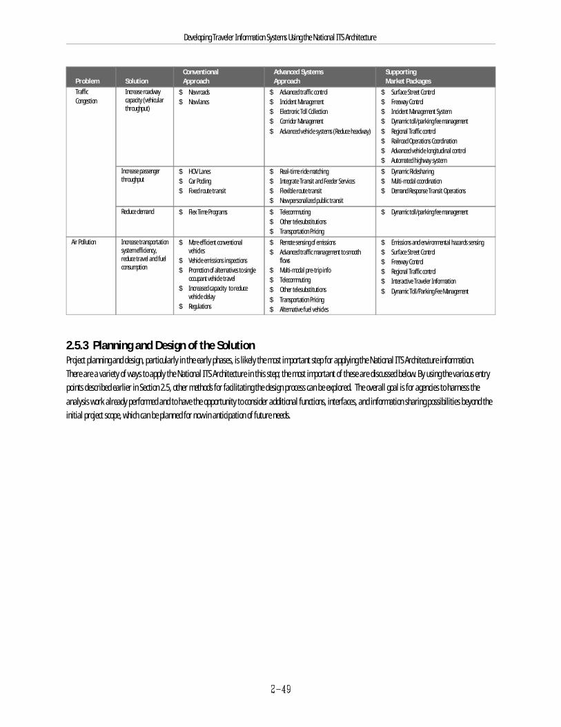
Developing Traveler Information Systems Using the National ITS Architecture
Problem Solution Approach Approach Market PackagesConventional Advanced Systems Supporting
Traffic Increase roadwayCongestion capacity (vehicular
throughput)
$ New roads $ Advanced traffic control $ Surface Street Control$ New lanes $ Incident Management $ Freeway Control
$ Electronic Toll Collection $ Incident Management System$ Corridor Management $ Dynamic toll/parking fee management$ Advanced vehicle systems (Reduce headway) $ Regional Traffic control
$ Railroad Operations Coordination$ Advanced vehicle longitudinal control$ Automated highway system
Increase passengerthroughput
$ HOV Lanes $ Real-time ride matching $ Dynamic Ridesharing$ Car Pooling $ Integrate Transit and Feeder Services $ Multi-modal coordination$ Fixed route transit $ Flexible route transit $ Demand Response Transit Operations
$ New personalized public transitReduce demand $ Flex Time Programs $ Telecommuting $ Dynamic toll/parking fee management
$ Other telesubstitutions$ Transportation Pricing
Air Pollution Increase transportationsystem efficiency,reduce travel and fuelconsumption
$ More efficient conventional $ Remote sensing of emissions $ Emissions and environmental hazards sensingvehicles
$ Vehicle emissions inspections flows$ Promotion of alternatives to single $ Multi-modal pre-trip info
occupant vehicle travel$ Increased capacity to reduce
vehicle delay$ Regulations
$ Advanced traffic management to smooth $ Surface Street Control
$ Telecommuting$ Other telesubstitutions$ Transportation Pricing$ Alternative fuel vehicles
$ Freeway Control$ Regional Traffic control$ Interactive Traveler Information$ Dynamic Toll/Parking Fee Management
2.5.3 Planning and Design of the SolutionProject planning and design, particularly in the early phases, is likely the most important step for applying the National ITS Architecture information.There are a variety of ways to apply the National ITS Architecture in this step; the most important of these are discussed below. By using the various entrypoints described earlier in Section 2.5, other methods for facilitating the design process can be explored. The overall goal is for agencies to harness theanalysis work already performed and to have the opportunity to consider additional functions, interfaces, and information sharing possibilities beyond theinitial project scope, which can be planned for now in anticipation of future needs.
Developing Traveler Information Systems Using the National ITS Architecture
The planning and design activities that are discussed in this section include:
g Determine Functional Requirements
g Identify Information Exchange Requirements
g Identify Standards
2.5.3.1 Determine Functional Requirements The National ITS Architecture can be used as an input to defining project or system functional requirements. This involves a more detailed look at the userservice requirements or market packages carried through from the previous step. Potential approaches include:
g User service requirements - The user service requirements associated with the proposed solution can be evaluated for their applicability to theproject. For example, they can be used to augment the functional specification that may be put out in an RFP for detailed design andprocurement. Using the Traceability Matrix, the process specifications that are associated with the relevant (selected) user service requirementscan also be analyzed. For those process specifications that are maintained in the system design, the data is available to relate those functions tothe rest of the logical and physical architecture.
g Market packages - The high-level architecture defined using the market packages can be further refined by examining the logical architectureelements that support these subsystems and architecture flows. The linked model can provide the maps to the underlying functions and dataflows of the logical architecture. The process specifications associated with the market packages can be tailored to satisfy more closely the localneeds or requirements that the solution must address. As originally defined, the market packages may identify more subsystems, equipmentpackages, or terminators than are required to satisfy the identified needs. While this presents a chance to drop unneeded features, it shouldalso be viewed as an opportunity to consider additional capabilities that may satisfy other needs at marginal cost. During the process ofdesigning the project, expansion capability may also be identified that can be planned for in future solutions. See Section 2.5.3.4 for anexample of how to aggregate and tailor market packages to meet local needs.
g Physical Architecture Subsystems - Even if the user service or market package approach isn’t followed initially, agencies should be able todetermine the relevant subsystems associated with a given project. Given a list of these subsystems, the physical architecture entry point can beused to determine the associated equipment packages, process specifications, and information flows. The underlying process specifications canbe evaluated for their applicability and potential contribution to the functional needs of the given project (or future ones). This entry point isparticularly useful for projects with a substantial amount of central equipment and software costs, such as a TMC upgrade.

InformationService Provider
Intermodal Transportation
Service Provider
VehicleMap Update
ProviderOther ISP
Personal InformationAccess
FinancialInstitutio
EmergencyManagement
PlanningSubsystem
Fleet & FreightManagement
TollAdministration
Traffic
Management
TransitManagement
Weather Service
Yellow Pages
ServiceProvider
Media
Remote TravelerSupport
ParkingManagemen
t
Developing Traveler Information Systems Using the National ITS Architecture
For each alternative presented above, the National ITS Architecture material can be used as is, dropped, modified, or added to as appropriate to thesituation. In most cases, additional performance requirements and other types of decisions will need to be included in the specification of a system before itcan be procured (even if the detailed design work is to be put out for bid). It is important to recognize that the National ITS Architecture does not addressreliability, availability, or maintainability. These and other operational and maintenance needs must be added to any requirements definition or systemspecification.
Unique local needs that are not covered as part of the 30 user services will also require the addition of subsystems or functions that are outside theNational ITS Architecture. These types of elements may represent legacy system functions or portions of legacy systems. The addition of functionality,subsystems, and external interfaces (terminators) that are not part of the National ITS Architecture is part of the process of tailoring the solutionarchitecture to satisfy the identified needs.
2.5.3.2 Identify Information Exchange RequirementsThe physical architecture identifies the physical subsystems and data flows among subsystems that will support the communications requirements of agiven project. It is important to identify physical data flows because they are the actual representation of communication ties among agencies andsubsystems. Figure 2.5-2 illustrates a simplified physical architecture data flow diagram for traveler information, focused on the information serviceprovider subsystem. Appendix C contains a more detailed listing and explanation of the physical architecture flows that are relevant to travelerinformation functions.
Figure 2.5-2. Example Physical Data Flows for Information Service Provider
In the process of specifying the information exchange requirements for the project, the underlying logical data flows associated with the identified physicalinformation flows should be evaluated for their inclusion in the definition of communication messages. In cases where data flows are not currentlyavailable (but might be in the future), accommodation of extra message fields in the software development for the project should be considered. This willlikely be done more economically if it is carried out now instead of having to modify the software later to handle the increased and changed needs forcommunications.
Developing Traveler Information Systems Using the National ITS Architecture
The Theory of Operations document can be used to obtain a better understanding of how the physical architecture elements work together to provide ITSservices. For example, it provides diagrams and descriptions indicating the intended sequencing of messages for particular user services. These diagramsillustrate the sharing of information between subsystems which is relevant in determining the working relationships needed between different agencies fora given project (e.g., between a public agency and a private sector traveler information provider). This type of information can be invaluable in developinga concept of operations for a project.
During the process of analyzing the possible information requirements contained in the National ITS Architecture, information exchanges beyond what wasoriginally planned may become desirable additions to the project. This could entail establishing working relationships and agreements with agencies thatwere not originally part of the project planning effort, which could lead to an expansion of the project steering team. The information exchanges identifiedin the National ITS Architecture can stimulate the discussion of operational roles and responsibilities and are therefore critical to establishing theoperations requirements for the project.
2.5.3.3 Identify StandardsThe rapid pace of progress in technology will introduce many new systems and devices into transportation systems. As transportation systems incorporateadvanced technology, there will be a need for standards to promote multi-vendor interoperability and ease of integration. With standards, it is simpler toshare data and communicate between transportation systems, particularly between agencies within the same region. Without standards, it is more difficultto integrate transportation systems with each other, and consequently there is a danger of isolating systems and limiting their potential effectiveness insolving a region’s transportation needs and problems.
One of the major reasons for developing the National ITS Architecture was to identify where standard system interfaces were needed. Because the NationalITS Architecture is serving as the common foundation for the ongoing ITS standards development work, factoring it into your current system enhancementswill facilitate the transition to a standard interface definition in the future. The Standards Requirements document contains detailed information on therequirements for 12 high-priority standards packages.
Agencies can take advantage of these standards as they emerge by specifying their use in procurement packages. Among the pertinent national ITSstandards development activities in process are the ATIS data dictionary, ATIS message data flow, ITS data bus (IDB), and in-vehicle system interfaces.Appendix A contains sources for additional information on standards development activities that are relevant to traveler information projects.
Agencies should also keep in mind that a variety of existing communications and information-based standards, which may have been created for otherreasons, are applicable to ITS projects and are being used in systems today.
2.5.3.4 Market Package Aggregation and Modification IllustrationTo illustrate some of the concepts of Section 2.5.3, this subsection illustrates the use of market packages as a way to create a high-level physicalarchitecture that can be further tailored to address local requirements.
As market packages are selected to address the given problems and needs, they may be aggregated by connecting or overlapping duplicate subsystems. The subsystems are connected by architecture flows that define subsystem interfaces. The aggregation of market packages will result in a high-levelphysical architecture that has been extracted from the National ITS Architecture and will represent a starting point for refinement and tailoring to uniquelocal needs or requirements. For example, the Surface Street Control and Incident Management System market packages might be found to be the mostapplicable solutions to the identified problem.
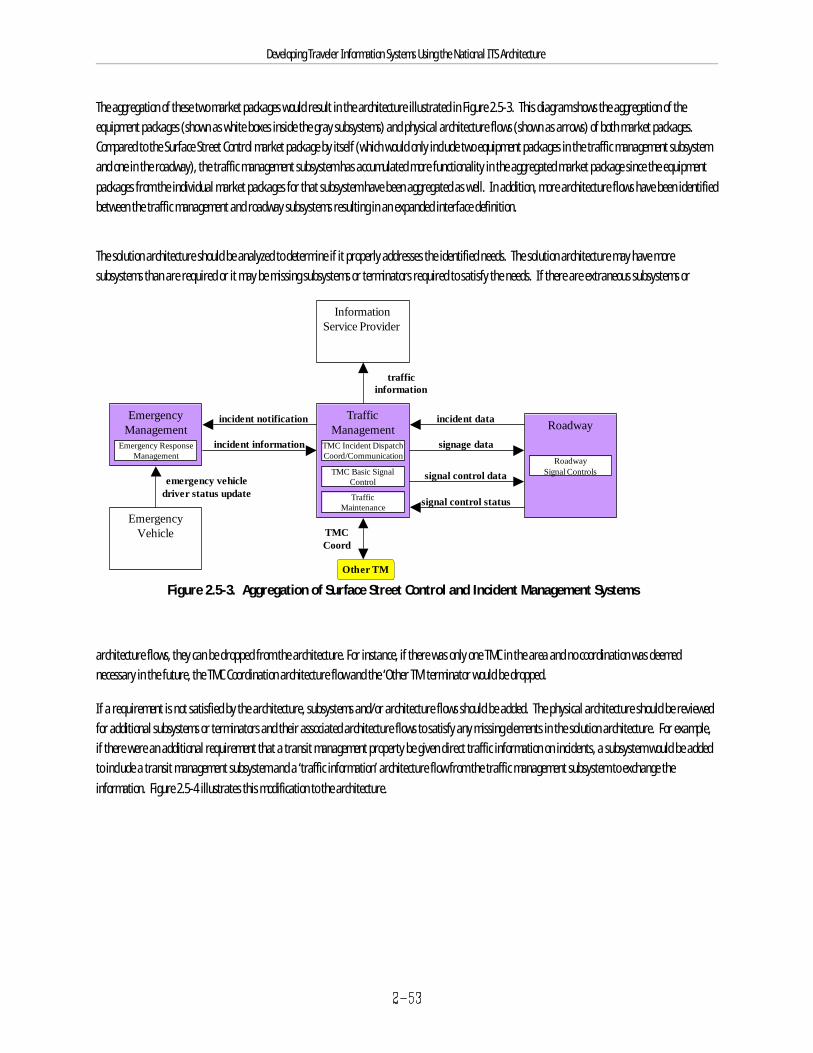
Roadway
RoadwaySignal Controlssignal control data
signal control status
TrafficManagement
TMC Incident DispatchCoord/Communication
incident notification
incident information
EmergencyManagement
Emergency ResponseManagement
InformationService Provider
EmergencyVehicle
emergency vehicledriver status update
trafficinformation
incident data
signage data
Other TM
TMCCoord
TMC Basic SignalControl
TrafficMaintenance
Developing Traveler Information Systems Using the National ITS Architecture
Figure 2.5-3. Aggregation of Surface Street Control and Incident Management Systems
The aggregation of these two market packages would result in the architecture illustrated in Figure 2.5-3. This diagram shows the aggregation of theequipment packages (shown as white boxes inside the gray subsystems) and physical architecture flows (shown as arrows) of both market packages.Compared to the Surface Street Control market package by itself (which would only include two equipment packages in the traffic management subsystemand one in the roadway), the traffic management subsystem has accumulated more functionality in the aggregated market package since the equipmentpackages from the individual market packages for that subsystem have been aggregated as well. In addition, more architecture flows have been identifiedbetween the traffic management and roadway subsystems resulting in an expanded interface definition.
The solution architecture should be analyzed to determine if it properly addresses the identified needs. The solution architecture may have moresubsystems than are required or it may be missing subsystems or terminators required to satisfy the needs. If there are extraneous subsystems or
architecture flows, they can be dropped from the architecture. For instance, if there was only one TMC in the area and no coordination was deemednecessary in the future, the TMC Coordination architecture flow and the ‘Other TM’ terminator would be dropped.
If a requirement is not satisfied by the architecture, subsystems and/or architecture flows should be added. The physical architecture should be reviewedfor additional subsystems or terminators and their associated architecture flows to satisfy any missing elements in the solution architecture. For example,if there were an additional requirement that a transit management property be given direct traffic information on incidents, a subsystem would be addedto include a transit management subsystem and a ‘traffic information’ architecture flow from the traffic management subsystem to exchange theinformation. Figure 2.5-4 illustrates this modification to the architecture.
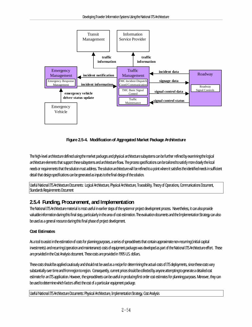
Roadway
RoadwaySignal Controlssignal control data
signal control status
TrafficManagement
TMC Incident DispatchCoord/Communication
incident notification
incident information
EmergencyManagement
Emergency ResponseManagement
InformationService Provider
EmergencyVehicle
emergency vehicledriver status update
trafficinformation
incident data
signage data
TMC Basic SignalControl
TrafficMaintenance
TransitManagement
trafficinformation
Developing Traveler Information Systems Using the National ITS Architecture
Figure 2.5-4. Modification of Aggregated Market Package Architecture
The high-level architecture defined using the market packages and physical architecture subsystems can be further refined by examining the logicalarchitecture elements that support these subsystems and architecture flows. The process specifications can be tailored to satisfy more closely the localneeds or requirements that the solution must address. The solution architecture will be refined to a point where it satisfies the identified needs in sufficientdetail that design specifications can be generated as inputs to the final design of the solution.
Useful National ITS Architecture Documents: Logical Architecture, Physical Architecture, Traceability, Theory of Operations, Communications Document,Standards Requirements Document
2.5.4 Funding, Procurement, and ImplementationThe National ITS Architecture material is most useful in earlier steps of the system or project development process. Nevertheless, it can also providevaluable information during this final step, particularly in the area of cost estimation. The evaluation documents and the Implementation Strategy can alsobe used as a general resource during this final phase of project development.
Cost Estimates
As a tool to assist in the estimation of costs for planning purposes, a series of spreadsheets that contain approximate non-recurring (initial capitalinvestments) and recurring (operation and maintenance) costs of equipment packages was developed as part of the National ITS Architecture effort. Theseare provided in the Cost Analysis document. These costs are provided in 1995 U.S. dollars.
These costs should be applied cautiously and should not be used as a recipe for determining the actual costs of ITS deployments, since these costs varysubstantially over time and from region to region. Consequently, current prices should be collected by anyone attempting to generate a detailed costestimate for an ITS application. However, the spreadsheets can be useful in producing first order cost estimates for planning purposes. Moreover, they canbe used to determine which factors affect the cost of a particular equipment package.
Useful National ITS Architecture Documents: Physical Architecture, Implementation Strategy, Cost Analysis
Developing Traveler Information Systems Using the National ITS Architecture
2.6 Traveler Information Project Application ScenariosThe National ITS Architecture can be used to identify the functions to be integrated into a new or existing traveler information system, and to determinewhat standards, information flows, and equipment/devices are needed to implement those functions. This section will step through two representativetraveler information system ITS application scenarios to help illustrate how the National ITS Architecture can be used to design and deploy travelerinformation systems. The two scenarios are:
g Public-Private Traveler Information Center (Section 2.6.1)
g Transit User Information System (Section 2.6.2)
Each of the scenarios includes a brief presentation of each of the four general steps referenced throughout this section, but is tailored to illustrate differentaspects of the previously presented guidance on applying the National ITS Architecture.
Developing Traveler Information Systems Using the National ITS Architecture
2.6.1 Public-Private Traveler Information Center Scenario (Using Market Packages)
One challenge facing transportation managers is that of establishing, operating, and maintaining, traveler information systems which will providetransportation users the kind of information which will influence the routes or modes these travelers take. Furthermore, in forever decreasing budgetaryclimates, establishing public-private partnerships to accomplish these goals is paramount.
This scenario illustrates the use and tailoring of market packages and their supporting cost analysis and highlights the consideration of standards.
2.6.1.1 Identification of Needs or ProblemsA large multi-year freeway construction project is being planned. Because the freeway passes through a metropolitan area, it is anticipated that theconstruction project will create large-scale disruption of the transportation system. These are summarized below:
g Roadways will be closed and detours will be implemented.
g Buses will be re-routed, and occasionally schedules will be changed.
g The freeway, a route to a major metropolitan airport, will be affected – tourists and out of town travelers will be affected.
Existing SystemsThe metropolitan region has a number of existing ITS systems. These systems and additional considerations associated with the development of thetraveler information system portion of the construction project are discussed below.
Media Interface—Currently, the media interface to traffic-related operations is traditional face-to-face and voice telephone. Virtually none of theinteraction with the media is automated.
Traffic Management Systems—The City currently operates a traffic signal control system with about 400 intersections, and has a traffic managementcenter. The State district office operates a freeway management system (200 miles of freeway) which includes 6 variable message signs (VMS) and 6closed-circuit television (CCTV) cameras located at major interchanges. In addition, police officers at the traffic management center help coordinateincident management activities.
Transit Management Systems—The County transit bureau operates a bus transit system of 100 buses and has recently started a project to implement anautomated vehicle location (AVL) system for its fleet. The County transit bureau also has a new bus scheduling system.
Emergency Management Systems—A number of emergency management systems are in operation in the region.
Developing Traveler Information Systems Using the National ITS Architecture
Objectives The primary objective of this effort is simply to minimize the impact of this construction on travelers. In order to meet this objective, an efficient meansmust be established for disseminating information between transportation systems and institutions and passing it on to travelers.
2.6.1.2 Identification of SolutionsThe State Department of Transportation, responsible for the freeway system, has taken the lead to form a coalition of public and private agencies that willwork together to maintain optimal performance of the transportation network during construction. Public agencies include: the City which manages thesurface street network, the County which operates the bus transit service, the Airport Authority, and State, City and County emergency managementservices—law enforcement, fire and rescue, and emergency medical. Private agencies will be involved in the dissemination of traveler information—traffic reporting agencies, news media, and cable TV.
The coalition has decided to implement a public-private Traveler Information Center (TIC) to process and disseminate all transportation-relatedinformation. The TIC will be the information service provider and single collection point for transportation information. The TIC will provide information tothe general public, travelers and businesses, and inform motorists, and the traveling public of transit schedule changes and route changes, and roadwayclosures and diversions. At the airport, kiosks will provide information on transit and traffic conditions to mitigate the impact to tourists and out of towntravelers.
The TIC will be responsible for the Information Service Provider subsystem, the Remote Traveler subsystem, and the Personal Information Access subsystemfunctions. Afterwards, the system will form a basis for a regional traveler information system. This is shown in Figure 2.6-1.
The different entities and how each will interact with the TIC are addressed below:
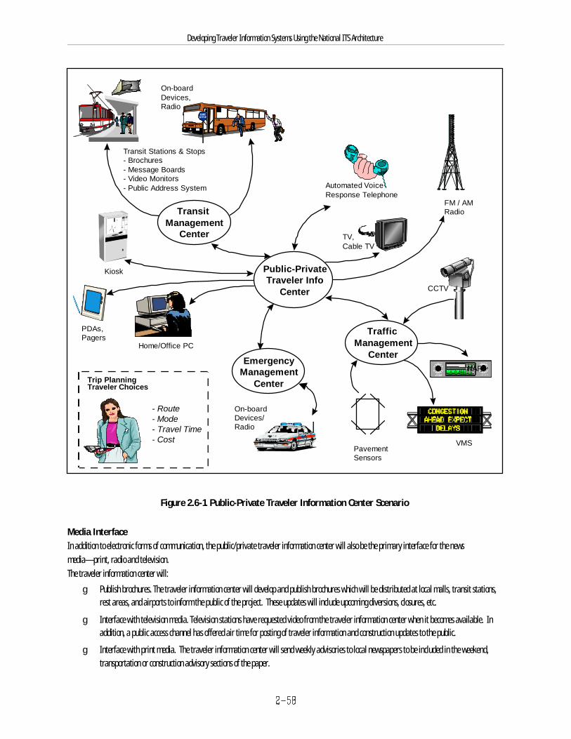
On-boardDevices/Radio
Transit Stations & Stops- Brochures- Message Boards- Video Monitors- Public Address System
TransitManagement
Center
TrafficManagement
CenterEmergency
ManagementCenter
Public-PrivateTraveler Info
Center
On-boardDevices,Radio
TV,Cable TV
CCTV
FM / AMRadio
Kiosk
PDAs,Pagers
Home/Office PC
Automated VoiceResponse Telephone
PavementSensors
VMS
HARTrip PlanningTraveler Choices
- Route- Mode- Travel Time- Cost
Developing Traveler Information Systems Using the National ITS Architecture
Figure 2.6-1. Public-Private Traveler Information Center Scenario
Media Interface In addition to electronic forms of communication, the public/private traveler information center will also be the primary interface for the newsmedia—print, radio and television. The traveler information center will:
g Publish brochures. The traveler information center will develop and publish brochures which will be distributed at local malls, transit stations,rest areas, and airports to inform the public of the project. These updates will include upcoming diversions, closures, etc.
g Interface with television media. Television stations have requested video from the traveler information center when it becomes available. Inaddition, a public access channel has offered air time for posting of traveler information and construction updates to the public.
g Interface with print media. The traveler information center will send weekly advisories to local newspapers to be included in the weekend,transportation or construction advisory sections of the paper.
Developing Traveler Information Systems Using the National ITS Architecture
g Make traffic, transit, and weather information available.
g Hold press conferences to inform the media and the public about the project, project schedule, project status, and potential benefits.
Traffic Management Systems The traffic management systems will provide information on roadway closures, congestion, incidents, and diversion routes to the TIC. Variable messagesign (VMS) coverage will be expanded to cover additional routes and be used to coordinate planned diversion routes. The traffic management center willalso introduce highway advisory radio (HAR) to the region. HAR and portable VMS will be procured and used both during and after completion of theconstruction project.
The traveler information system will expand the roadway video surveillance system and make video available to emergency management, transitmanagement, the TIC, and the media. Video from an additional 6 surveillance cameras will be installed as part of this project. Video images will be sentto the traveler information center where it will then be distributed to the traffic management center and transit management center. Provisions will bemade to send existing camera video from the traffic management center to the traveler information center where it will be redistributed to others in thecoalition. The media will use the video information for television traffic reports, and the transit and emergency management centers will use theinformation to assist in routing decisions.
Transit Management SystemThe County transit bureau scheduling system will be used during the construction project to determine optimal bus route changes and schedulemodifications. This information will be made available to the TIC to support travelers.
Emergency Management Systems The various emergency management centers want to maintain current levels of service and response times during construction. This can be accomplished ifthey are well informed of roadway incidents, street closures, and areas of traffic congestion. Emergency vehicle routing is key to response timeperformance.
In-Vehicle Systems Vehicle communication alternatives will be studied during the project. This study was added to the project in response to the new bus location system beingimplemented, and interest on the part of a large car rental agency for dynamic route information (incidents, construction advisories, etc.). The addition ofin-vehicle equipment will not be funded by the construction project.
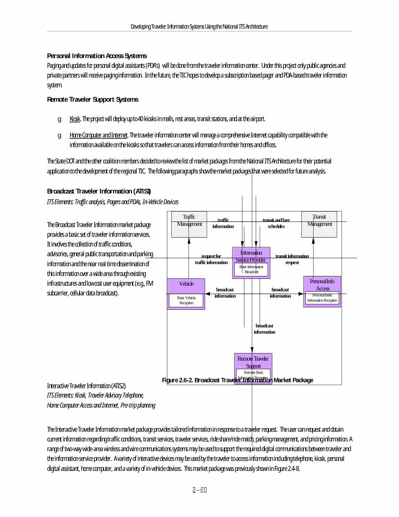
Personal InfoAccess
Remote TravelerSupport
Vehicle
Personal BasicInformation Reception
Remote BasicInformation Reception
Basic VehicleReception
broadcastinformation
broadcastinformation
broadcastinformation
TrafficManagement
TransitManagement
InformationService Provider
Basic InformationBroadcast
trafficinformation
transit and fareschedules
request fortraffic information
transit informationrequest
Developing Traveler Information Systems Using the National ITS Architecture
Figure 2.6-2. Broadcast Traveler Information Market Package
Personal Information Access Systems Paging and updates for personal digital assistants (PDA’s) will be done from the traveler information center. Under this project only public agencies andprivate partners will receive paging information. In the future, the TIC hopes to develop a subscription based pager and PDA-based traveler informationsystem.
Remote Traveler Support Systems
g Kiosk. The project will deploy up to 40 kiosks in malls, rest areas, transit stations, and at the airport.
g Home Computer and Internet. The traveler information center will manage a comprehensive Internet capability compatible with theinformation available on the kiosks so that travelers can access information from their homes and offices.
The State DOT and the other coalition members decided to review the list of market packages from the National ITS Architecture for their potentialapplication to the development of the regional TIC. The following paragraphs show the market packages that were selected for future analysis.
Broadcast Traveler Information (ATIS1)ITS Elements: Traffic analysis, Pagers and PDAs, In-Vehicle Devices
The Broadcast Traveler Information market packageprovides a basic set of traveler information services. It involves the collection of traffic conditions,advisories, general public transportation and parkinginformation and the near real time dissemination ofthis information over a wide area through existinginfrastructures and low cost user equipment (e.g., FMsubcarrier, cellular data broadcast).
Interactive Traveler Information (ATIS2)ITS Elements: Kiosk, Traveler Advisory Telephone,Home Computer Access and Internet, Pre-trip planning
The Interactive Traveler Information market package provides tailored information in response to a traveler request. The user can request and obtaincurrent information regarding traffic conditions, transit services, traveler services, ride share/ride match, parking management, and pricing information. Arange of two-way wide-area wireless and wire communications systems may be used to support the required digital communications between traveler andthe information service provider. A variety of interactive devices may be used by the traveler to access information including telephone, kiosk, personaldigital assistant, home computer, and a variety of in-vehicle devices. This market package was previously shown in Figure 2.4-8.
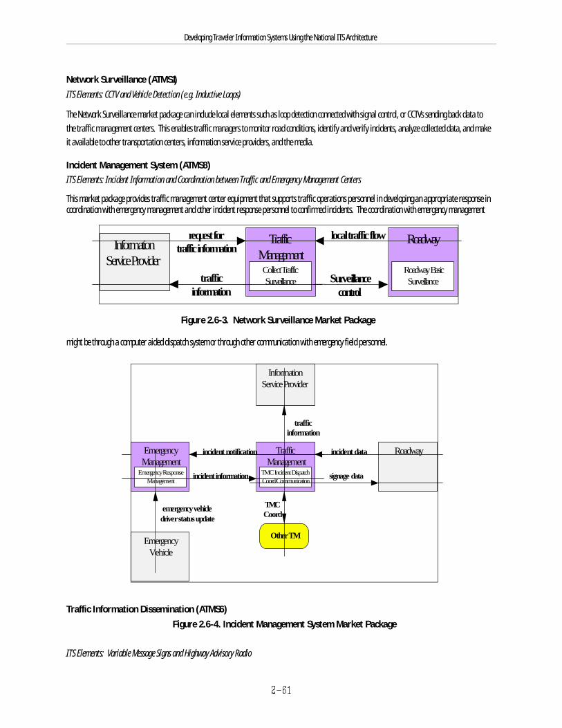
TrafficManagementCollect TrafficSurveillance
Roadway
Roadway BasicSurveillance
InformationService Provider
trafficinformation
request fortraffic information
local traffic flow
Surveillancecontrol
TrafficManagement
TMC Incident DispatchCoord/Communication
Roadway
Other TM
TMCCoord
incident notificationEmergencyManagement
Emergency ResponseManagement
incident data
incident information
InformationService Provider
trafficinformation
signage data
EmergencyVehicle
emergency vehicle driver status update
Developing Traveler Information Systems Using the National ITS Architecture
Figure 2.6-3. Network Surveillance Market Package
Figure 2.6-4. Incident Management System Market Package
Network Surveillance (ATMS1)ITS Elements: CCTV and Vehicle Detection (e.g. Inductive Loops)
The Network Surveillance market package can include local elements such as loop detection connected with signal control, or CCTVs sending back data tothe traffic management centers. This enables traffic managers to monitor road conditions, identify and verify incidents, analyze collected data, and makeit available to other transportation centers, information service providers, and the media.
Incident Management System (ATMS8)ITS Elements: Incident Information and Coordination between Traffic and Emergency Management Centers
This market package provides traffic management center equipment that supports traffic operations personnel in developing an appropriate response incoordination with emergency management and other incident response personnel to confirmed incidents. The coordination with emergency management
might be through a computer aided dispatch system or through other communication with emergency field personnel.
Traffic Information Dissemination (ATMS6)
ITS Elements: Variable Message Signs and Highway Advisory Radio
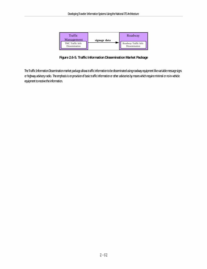
TrafficManagementTMC Traffic Info
Dissemination
Roadwaysignage data
Roadway Traffic InfoDissemination
Developing Traveler Information Systems Using the National ITS Architecture
Figure 2.6-5. Traffic Information Dissemination Market Package
The Traffic Information Dissemination market package allows traffic information to be disseminated using roadway equipment like variable message signsor highway advisory radio. The emphasis is on provision of basic traffic information or other advisories by means which require minimal or no in-vehicleequipment to receive the information.
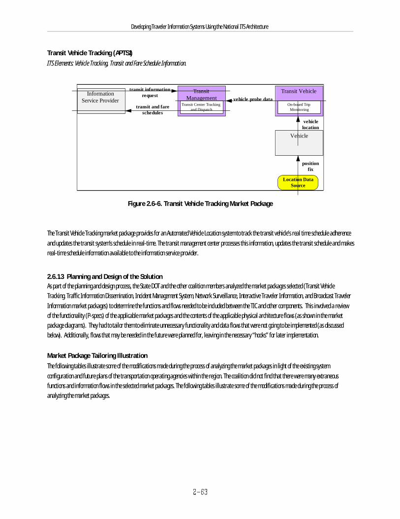
TransitManagement
Transit Center Trackingand Dispatch
Transit Vehicle
On-board TripMonitoring
InformationService Provider
transit and fareschedules
transit informationrequest
vehicle probe data
Location DataSource
positionfix
Vehicle
vehiclelocation
Developing Traveler Information Systems Using the National ITS Architecture
Transit Vehicle Tracking (APTS1)ITS Elements: Vehicle Tracking, Transit and Fare Schedule Information.
Figure 2.6-6. Transit Vehicle Tracking Market Package
The Transit Vehicle Tracking market package provides for an Automated Vehicle Location system to track the transit vehicle’s real time schedule adherenceand updates the transit system’s schedule in real-time. The transit management center processes this information, updates the transit schedule and makesreal-time schedule information available to the information service provider.
2.6.1.3 Planning and Design of the SolutionAs part of the planning and design process, the State DOT and the other coalition members analyzed the market packages selected (Transit VehicleTracking, Traffic Information Dissemination, Incident Management System, Network Surveillance, Interactive Traveler Information, and Broadcast TravelerInformation market packages) to determine the functions and flows needed to be included between the TIC and other components. This involved a reviewof the functionality (P-specs) of the applicable market packages and the contents of the applicable physical architecture flows (as shown in the marketpackage diagrams). They had to tailor them to eliminate unnecessary functionality and data flows that were not going to be implemented (as discussedbelow). Additionally, flows that may be needed in the future were planned for, leaving in the necessary “hooks” for later implementation.
Market Package Tailoring IllustrationThe following tables illustrate some of the modifications made during the process of analyzing the market packages in light of the existing systemconfiguration and future plans of the transportation operating agencies within the region. The coalition did not find that there were many extraneousfunctions and information flows in the selected market packages. The following tables illustrate some of the modifications made during the process ofanalyzing the market packages.
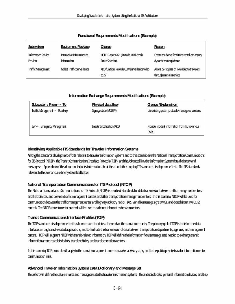
Developing Traveler Information Systems Using the National ITS Architecture
Functional Requirements Modifications (Example)
Subsystem Equipment Package Change Reason
Information Service Provider Information Route Selection) dynamic route guidance
Interactive Infrastructure HOLD P-spec 6.6.1 (Provide Multi-modal Create the hooks for future rental car agency
Traffic Management Collect Traffic Surveillance ADD function: Provide CCTV surveillance videoto ISP through media interface
Allows ISP to pass on live video to travelers
Information Exchange Requirements Modifications (Example)
Subsystem: From -> To Physical data flow Change /Explanation Traffic Management -> Roadway Signage data (MODIFY) Use existing system protocols/message conventions
ISP -> Emergency Management Incident notification (ADD) Provide incident information from TIC to variousEMCs.
Identifying Applicable ITS Standards for Traveler Information SystemsAmong the standards development efforts relevant to Traveler Information Systems and to this scenario are the National Transportation Communicationsfor ITS Protocol (NTCIP), the Transit Communications Interface Protocols (TCIP), and the Advanced Traveler Information System data dictionary andmessage set. Appendix A of this document includes information about these and other ongoing ITS standards development efforts. The ITS standardsrelevant to this scenario are briefly described below.
National Transportation Communications for ITS Protocol (NTCIP)The National Transportation Communications for ITS Protocol (NTCIP) is a suite of standards for data transmission between traffic management centersand field devices, and between traffic management centers and other transportation management centers. In this scenario, NTCIP will be used forcommunication between the traffic management center and highway advisory radio (HAR), variable message signs (VMS), and closed circuit TV (CCTV)controls. The NTCIP center to center protocol will be used to exchange information between centers.
Transit Communications Interface Profiles (TCIP)The TCIP standards development effort has been created to address the needs of the transit community. The primary goal of TCIP is to define the datainterfaces among transit-related applications, and to facilitate the transmission of data between transportation departments, agencies, and managementcenters. TCIP will augment NTCIP with transit-related information. TCIP will define the information flows (message sets) needed to exchange transitinformation among roadside devices, transit vehicles, and transit operations centers.
In this scenario, TCIP protocols will apply to the transit management center to traveler advisory signs, and to the public/private traveler information centercommunication links.
Advanced Traveler Information System Data Dictionary and Message Set This effort will define the data elements and messages related to traveler information systems. This includes kiosks, personal information devices, and trip
Developing Traveler Information Systems Using the National ITS Architecture
planning. In this scenario these messages will apply to the communication links between the traveler information center and the traveler informationdisplay devices (visual and audible).
2.6.1.4 Funding, Procurement, and ImplementationA phased approach has been selected which will permit early establishment of the TIC main functions. Future functions, such as subscription-basedpagers and PDA-based traveler information systems will be implemented as funding permits.
Cost AnalysisThe Cost Analysis document from the National ITS Architecture provides information that can help to generate an order-of-magnitude cost for this public-private traveler information center scenario.
As discussed previously, market packages are composed of equipment packages. As a tool to assist in the estimation of costs, the National ITS Architectureincludes a series of spreadsheets that provide order-of-magnitude costs of each equipment package in 1995 U.S. dollars. These costs are divided intoinitial non-recurring costs (capital costs) and recurring costs (operations and maintenance). Moreover, these spreadsheets may be used to determinewhich factors affect the cost of a particular equipment package. Table 2.6-1 shows the cost spreadsheet for the illustrative implementation of the BasicInformation Broadcast (ISP 1) equipment package.
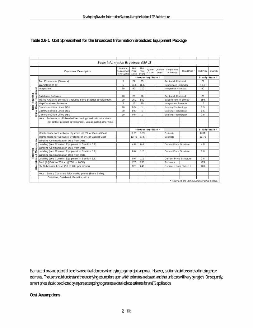
Basic Information Broadcast (ISP 1)ISP1
Equipment DescriptionYears to
Replacement (Life Cycle)
Unit Price
(Low)
Unit Price (High)
Quantity (Low)
Quantity (High)
Comparative Technology
Retail Price * Unit Price Quantity
Introductory State * Steady State *Two Processors (Servers) 5 27 33 Per Loral, Rockwell 27Workstations (5) 5 13.5 16.5 Experience in Similar 13.5Integration 20 90 110 Integration Projects 90
Database Software 20 25 50 Per Loral, Rockwell 25Traffic Analysis Software (includes some product development) 20 250 500 Experience in Similar 250Map Database Software 2 15 30 Integration Projects 15Communication Lines DS1 20 0.5 1 Existing Technology 0.5Communication Lines DS0 20 0.5 1 Existing Technology 0.5Communication Lines DS0 20 0.5 1 Existing Technology 0.5Note : Software is off-the-shelf technology and unit price does not reflect product development, unless noted otherwise.
Introductory State * Steady State *Maintenance for Hardware Systems @ 2% of Capital Cost 0.81 0.99 Estimate 0.81Maintenance for Software Systems @ 5% of Capital Cost 13.75 27.5 Estimate 13.75Wireline Communication DS1 from DataLoading (see Common Equipment in Section 5.6) 4.8 8.4 Current Price Structure 4.8Wireline Communication DS0 from DataLoading (see Common Equipment in Section 5.6) 0.6 1.2 Current Price Structure 0.6Wireline Communication DS0 from DataLoading (see Common Equipment in Section 5.6) 0.6 1.2 Current Price Structure 0.6Staff (2@50K to 75K +1@75K to 100K) 175 250 Estimate 175FM Subcarrier Lease (10 to 20K per month) 120 240 Estimate from Phase I 120
Note : Salary Costs are fully loaded prices (Base Salary, Overtime, Overhead, Benefits, etc.)
* All prices are in thousands of 1995 dollars.
Non
-Rec
urri
ng(In
itial
Cap
ital I
nves
tmen
t)R
ecur
ring
(Ope
ratio
ns &
Mai
nten
ance
)
Developing Traveler Information Systems Using the National ITS Architecture
Table 2.6-1. Cost Spreadsheet for the Broadcast Information Broadcast Equipment Package
Estimates of cost and potential benefits are critical elements when trying to gain project approval. However, caution should be exercised in using theseestimates. The user should understand the underlying assumptions upon which estimates are based, and that unit costs will vary by region. Consequently,current prices should be collected by anyone attempting to generate a detailed cost estimate for an ITS application.
Cost Assumptions
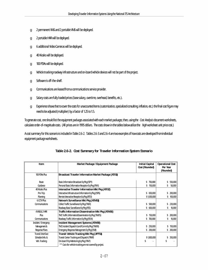
Developing Traveler Information Systems Using the National ITS Architecture
g 2 permanent VMS and 2 portable VMS will be deployed.
g 2 portable HAR will be deployed.
g 6 additional Video Cameras will be deployed.
g 40 Kiosks will be deployed.
g 100 PDAs will be deployed.
g Vehicle tracking roadway infrastructure and on-board vehicle devices will not be part of the project.
g Software is off-the-shelf.
g Communications are leased from a communications service provider.
g Salary costs are fully loaded prices (base salary, overtime, overhead, benefits, etc.).
g Experience shows that to cover the costs for unaccounted items (customization, specialized consulting, inflation, etc.) the final cost figure mayneed to be adjusted (multiplier) by a factor of 1.25 to 1.5.
To generate cost, one should list the equipment packages associated with each market packages; then, using the Cost Analysis document worksheets,calculate order-of-magnitude costs. (All prices are in 1995 dollars. The costs shown in the tables below utilize the high worksheet unit price cost.)
A cost summary for this scenario is included in Table 2.6-2. Tables 2.6-3 and 2.6-4 are two examples of how costs are developed from individualequipment package worksheets.
Table 2.6-2. Cost Summary for Traveler Information System Scenario
Item Market Package / Equipment Package Initial Capital Operational CostCost (Rounded) Per Year
(Rounded)100 PDAs Plus Broadcast Traveler Information Market Package (ATIS1)
Route Basic Information Broadcast Eq Pkg (ISP1) $ 750,000 $ 550,000 Guidance Personal Basic Information Reception Eq Pkg (PIA1) $ 150,000 $ 50,000
40 Kiosks Plus Interactive Traveler Information Mkt Pkg (ATIS2)Pre-Trip Interactive Infrastructure Information Eq Pkg (ISP6) $ 650,000 $ 200,000 Planning Remote Interactive Reception Eq Pkg (RTS1) $ 1,000,000 $ 100,000
6 CCTV Plus Network Surveillance Mkt Pkg (ATMS1)Communications Collect Traffic Surveillance Eq Pkg (TMS1) $ 500,000 $ 220,000
Roadway Basic Surveillance Eq Pkg (RS5) $ 600,000 $ 10,000 4 VMS & 2 HAR Traffic Information Dissemination Mkt Pkg (ATMS6)
Plus TMC Traffic InformationDissemination Eq Pkg (TMS15) $ 150,000 $ 200,000 Communications Roadway Traffic Information Eq Pkg (RS14) $ 700,000 $ 10,000
Incident / Emergency Incident Management Systems (ATMS8)Management & TMC Incident Dispatch Coord/Comm Eq Pkg (TMS10) $ 250,000 $ 150,000 Response Plans Emergency Response Management Eq Pkg (EM3) $ 200,000 $ 200,000
Transit Interface Transit Vehicle Tracking Mkt Pkg (APTS1)Schedule Info. & Transit Center Tracking and Dispatch (TRM7) $ 1,800,000 $ 350,000 Veh. Tracking On-board Trip Monitoring Eq Pkg (TRV7) $ - $ -
** Cost sfor vehicle tracking are not covered by project.

Developing Traveler Information Systems Using the National ITS Architecture
Traveler Info. System Total Preliminary Cost $ 6,750,000 $ 2,040,000 Scenario Total Estimated Cost (Inc. Adjustment Factor of 1.4) $ 9,450,000 $ 2,856,000
Mkt Pkg = Market Package Eq Pkg = Equipment Package

Developing Traveler Information Systems Using the National ITS Architecture
Table 2.6-3. Cost for Interactive Traveler Information (ATIS2) Market Package
Capital Investment Interactive Infrastructure Information Equipment Package Cost - Additional Processor/Server $ 16,500 - Workstations (2) $ 6,600 - Integration $ 110,000 - Trip Planning Software $ 500,000 - Communication Lines (DS1) $ 1,000 Sub Total $ 634,100
Operations and Interactive Infrastructure Information Equipment Package Cost Maintenance / Year
- Maintenance of Hardware Systems $ 462 - Maintenance of Software Systems $ 25,000 - Wireline Communication From Data Loading (DS1) $ 8,400 - Staff $ 150,000 Sub Total $ 183,862
Capital Investment Remote Interactive Information Reception Equipment Package Cost - Software Upgrade and Integration to Existing Kiosks $ 12,000- Interactive Information Display Interface $ 8,000 - Additional Interface to Communication Lines $ 2,000 Sub Total $ 22,000
Operations and Remote Interactive Information Reception Equipment Package Cost Maintenance / Year
- Maintenance of Interface for Display $ 800 - Wireline Communication (RTS to ISP included in RTS) $ 1,200- RTS to Map Update Provider Communication (DS0) $ 1,200 - RTS to TRMS Wireline Communication DS3 from Data Loading $ 72,000 Sub Total $ 75,200
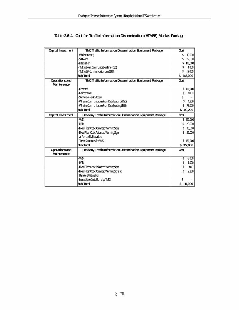
Developing Traveler Information Systems Using the National ITS Architecture
Table 2.6-4. Cost for Traffic Information Dissemination (ATMS6) Market Package
Capital Investment TMC Traffic Information Dissemination Equipment Package Cost - Workstation (1) $ 10,000 - Software $ 22,000 - Integration $ 110,000 - TMC to Event Communication Line (DS0) $ 1,000 - TMC to ISP Communication Line (DS3) $ 5,000 Sub Total $ 148,000
Operations and TMC Traffic Information Dissemination Equipment Package Cost Maintenance
- Operator $ 110,000 - Maintenance $ 7,000 - Shortwave Radio Access $ - - Wireline Communication From Data Loading (DS0) $ 1,200 - Wireline Communication From Data Loading (DS3) $ 72,000 Sub Total $ 190,200
Capital Investment Roadway Traffic Information Dissemination Equipment Package Cost - VMS $ 120,000 - HAR $ 20,000 - Fixed Fiber Optic Advanced Warning Signs $ 15,000 - Fixed Fiber Optic Advanced Warning Signs $ 22,000 at Remote EMS Location.- Tower Structures for VMS $ 150,000 Sub Total $ 327,000
Operations and Roadway Traffic Information Dissemination Equipment Package Cost Maintenance
- VMS $ 6,000 - HAR $ 1,000 - Fixed Fiber Optic Advanced Warning Signs $ 800 - Fixed Fiber Optic Advanced Warning Signs at $ 2,200 Remote EMS Location.- Leased Line Costs Borne by TMCS $ - Sub Total $ 10,000
Developing Traveler Information Systems Using the National ITS Architecture
2.6.2 Transit User Information System (Using User Service Requirements)In this scenario, the County transit agency is working together with the City traffic operations center to utilize AVI/AVL transit probe data to implement atransit signal priority system as well as to enhance transit user schedule adherence information on the dial-in automated phone lines and transit userkiosks.
Transit vehicle priority provides real-time coordination between the surface street traffic management system and the transit management system. Integration of these two systems can reduce overall delay, improve the consistency of transit travel times and headways, improve traveler mobility, andincrease economic productivity through ridership. The most obvious benefit, however, is to travelers on buses who will experience more consistent traveltimes on routes, and fewer delays at stops and transfer points. Benefit to the traffic signal control agency comes in the form of additional surveillancedata, including route travel times and vehicle probe data.
Signal priority for transit vehicles can be of the greatest benefit to buses that are behind schedule, providing a way for a bus to make up time along aroute. When a bus is behind schedule, it can request priority—extension of the green phase—allowing passage through the intersection.
In this scenario, the County transit agency is responding to a noticeable decline in transit ridership over several years. Inherent with this decline is anincrease in arterial traffic delays and congestion. The City operates a Traffic Management Center containing a centralized traffic signal control system. Currently, the City’s traffic signal control system operates independently of the County Transit Management System, i.e., it is wholly self-contained anddoes not communicate with any other agency transportation management system. County Transit is proposing several small projects to the City in hopes ofintegrating the transit signal priority into the City signal control operations. A joint working group of City traffic signal and County transit engineers hasbeen formed to develop a solution that meets the needs of both team members.
This scenario illustrates the use of user service requirements as an approach for guiding the development of functional requirements for a system.
2.6.2.1 Identification of Problems and NeedsThe first job of the joint working group was to identify and refine all of the relevant transportation needs, objectives or problems.
Existing SystemsThe County transit agency currently has a previously installed automatic vehicle identification and location system. The AVI/AVL system communicates busidentification to the roadside reader over a DSRC link. Currently, this information is communicated solely to the transit management center over dedicatedland lines for the purpose of tracking the location of fleet vehicles. No further processing of the location data is performed. The City operates andcoordinates the traffic signals throughout the City. Signal control is largely based on time-of-day plans and coordination plans are determined by networksections or corridors. At many intersections, individual signal timing adjustments are made locally depending on demand. The City traffic signal systemand the County transit systems do not currently communicate with each other.
Objectives The County transit agency wants to accomplish several objectives through several small projects. Working with the City traffic operations department, theyhope to get a large return on their investment (through increased ridership) by taking advantage of integration benefits. The joint working groupidentified the following needs:
g The County must know real time location of its fleet of transit buses.
g The County must process bus location information to determine link travel times.
g County transit must disseminate real time schedule information to potential transit users through a series of user kiosks deployed at key transit

Developing Traveler Information Systems Using the National ITS Architecture
locations, employment sites, and activity centers throughout the County.
g County transit must disseminate pre-trip travel information to potential users’ homes and workplaces through an Internet web site.
g In order to improve travel times, reduce inconsistent transit service and thereby increase ridership, County transit must integrate AVL probeinformation with the City-operated transit signal priority system.
g The City wants the link travel times provided by transit in order to optimize the traffic signal operations.
2.6.2.2 Identification of Solutions The joint working group’s aim was to utilize much of the existing infrastructure from the AVL and traffic signal control systems. Coordination of the transitpriority system with the traffic signal system is successful when the respective facility managers are aware of traffic conditions on the transportationnetwork as well as transit schedule adherence, and they coordinate a timely response according to those conditions. Coordination between the two networkswill involve using the field devices (AVL and signal controllers) on their respective systems to implement cooperative responses.
One approach to satisfying the needs of both team members is to tie AVI/AVL readers to selected traffic signals. In addition to this integration of trafficand transit systems, the roadside AVI/AVL readers will be upgraded to process identification information. The identification and time information will beprocessed at the transit management center to determine the County transit bus probe vehicle speed and link travel time. This information will be passedfrom the transit management center to transit users in the form of schedule adherence and expected travel time and arrival time data through a series oftransit kiosks and an Internet site. The County transit management center will also pass probe data to the City traffic signal control operations in order toallow adjustments to signal operations.
Developing Traveler Information Systems Using the National ITS Architecture
The joint working group agreed to investigate the Pre-Trip Travel Information, Traffic Control, Ride Matching and Reservation,and Traveler Services Information user services to determine if their underlying requirements and physical and logical architecture definitioncould be used to support the planning and design of the project.
Other ConsiderationsThe joint working group also identified several capabilities that might be included in the future.
g Inclusion of private automobiles into the mix of probes for determining travel link times.
g Capability to provide this information to the operations centers of other agencies.
g Potential for all transportation information (including transit-specific information) to be passed to an ISP for processing and dissemination. This would reduce the need for transit to purchase and maintain separate kiosks around the region and allow the information to be provided ina variety of other ways to travelers.
The County transit and City traffic agencies have agreed to investigate the use of ITS standards for communications.
2.6.2.3 Planning and Design At this point, the County, as the lead in the project, procured the services of a consultant to plan, design and implement the solutions identified above. Thejoint working group asked the consultant to use the selection and tailoring of user service requirements as way to guide the development of functionalrequirements for the project. The Travel and Transportation Management user services that apply to this scenario are Traffic Control, Traveler ServicesInformation, Ride Matching and Reservation, and Pre-Trip Travel Information. A Functional Description document was prepared from the objectives.
User Service Requirements IllustrationUser services are defined in the National ITS Architecture Traceability document. As an example, a list of requirements from Appendix A of the Traceabilitydocument that defines the “Pre-Trip Traveler Information” user service in detail is provided below with the specific requirements selected to be applied inthis design shown as bolded. Similar tables were produced for the other two user services that were investigated. Appendix B of the Traceability documentwas then used to select the process specifications (P-specs) that correspond to the selected user service requirements. These were used in the preparationof the Functional Description document, along with many additional locally derived requirements and operational concepts forwarded from the jointworking group.
The physical data flows needed to implement the necessary portions of the Pre-Trip Travel Information user service were selected from Appendix A of thePhysical Architecture document and were incorporated into the procurement specification by the consultant. An example of this is also provided below.

Developing Traveler Information Systems Using the National ITS Architecture
Developing Traveler Information Systems Using the National ITS Architecture
Physical Data Flows Required Selected from Appendix A of Physical Architecture. (Example)
Transit Vehicle to Transit Management: vehicle probe data
Transit User to Remote Traveler Support: traveler information request
Transit Vehicle Subsystem to Roadway Subsystem: local signal priority request
Information Service Provider to Remote Traveler: traveler information
Transit Management to Remote Traveler Support: transit and fare schedules
Applicable Standards - Transit Communications Interface Profiles (TCIP)The TCIP standards development effort has been created to address the needs of the transit community. The primary goal of TCIP is to define the datainterfaces among transit-related applications, and to facilitate the transmission of data between transportation departments, agencies, and managementcenters. TCIP will augment NTCIP with transit-related information. TCIP will define the information flows (message sets) needed to exchange transitinformation among roadside devices, transit vehicles, and transit operations centers.
In this scenario, TCIP protocols will apply to the transit vehicle to transit management center, and to the transit management center to traffic managementcenter communication links.
Advanced Traveler Information System Data Dictionary and Message Set This effort will define the data elements and messages related to traveler information systems. This includes kiosks, personal information devices, and tripplanning. In this scenario, these messages will apply to the communication links between the transit management center and the traveler informationdisplay devices (transit information kiosks).
2.6.2.4 Funding, Procurement and Implementation In consultation with the joint working group, the consultant then completed preparation of the design Plans, Specifications, and Cost Estimates (PS&Es). The City and County have decided to implement a transit vehicle probe system and will use TCIP as a standard for communicating information between AVLand the traffic signal control systems. The County will fund the development and installation of transit kiosks and an Internet-based application. It shouldbe noted that Information Service Provider functions are being formed by the County transit agency. However, the open design of this installation opensthe door for future applications where an ISP could take over traffic information dissemination responsibilities for the entire region. Figure 2.6-7 depictsthe integration of the two systems which will enable the solutions identified by the joint working group.
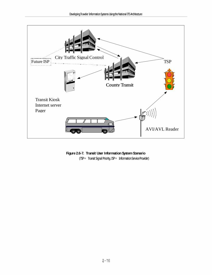
County Transit
City Traffic Signal Control
Transit KioskInternet serverPager
TSP
County Transit
Future ISP
AVI/AVL Reader
Developing Traveler Information Systems Using the National ITS Architecture
Figure 2.6-7. Transit User Information System Scenario (TSP = Transit Signal Priority, ISP = Information Service Provider)
Developing Traveler Information Systems Using the National ITS Architecture
2.7 Summary This section presented the key concepts of the National ITS Architecture and discussed in some detail how it can be applied to traveler information projectdevelopment activities. Two traveler information project application scenarios were presented which used realistic examples to illustrate these methods.
Some of the key themes of this section include:
g The key concepts and elements of the National ITS Architecture as presented in Sections 2.4.1-2.4.5 are interrelated and traceable in a varietyof ways.
g The National ITS Architecture tools are intended to augment and support existing ITS project development processes, and should be applied withengineering judgment in that context.
g There are many ways to apply the National ITS Architecture to the project development process.
g The National ITS Architecture tools are most applicable in the early stages of project development.
g The National ITS Architecture can be used to provide project developers with additional options to consider for information exchanges andfunctionality that may not have initially been conceived at the outset of the project.
g Using the National ITS Architecture should not be viewed as an all-or-nothing activity; rather, the material can be used as is, tailored, dropped,or added to as appropriate for the situation.
g The National ITS Architecture is available in several formats, including paper documents, Microsoft Access J relational databases, and a linkedHTML model, which provides access through a linked model.
g Several entry points or methods are also available which make accessing the applicable information more convenient.
A summary of how the National ITS Architecture can be used to support project development activities and the most relevant resource material is providedbelow:
Identification of Needs or Problems (Section 2.5.1)
T The National ITS Architecture can assist agencies in identifying ITS goals and objectives that are specific to their needs.
T The Vision Statement can also serve to foster general ideas about the types of local needs and problem that ITS can be used to address.
Useful National ITS Architecture Documents: Mission Definition, Vision Statement
Identification of Solutions (Section 2.5.2)T Agencies can use two major approaches for identifying possible solutions that are supported by the National ITS Architecture.
g User Services
g Market Packages
Developing Traveler Information Systems Using the National ITS Architecture
T Evaluation and Implementation Strategy documents have supporting information that can be referenced.
Useful National ITS Architecture Documents: Traceability Matrix, Implementation Strategy, Performance and Benefits Study
Planning and Design of the Solution (Section 2.5.3)T The National ITS Architecture can be used as an input to defining project or system functional requirements. Potential approaches include:
g User service requirements - The user service requirements associated with the proposed solution can be evaluated for theirapplicability to the project.
g Market packages - The high-level architecture defined using the market packages can be further refined by examining the logicalarchitecture elements that support these subsystems and architecture flows.
g Physical Architecture Subsystems - Agencies can determine the relevant subsystems associated with a given project and use this asan entry point to accessing the underlying architecture definition.
T The physical architecture can be used to support the definition of the information exchange requirements for a given project.
T The Standards Requirements document contains detailed information on the requirements for 12 high-priority standards packages, which canbe helpful towards the identification of standards for a given project.
Useful National ITS Architecture Documents: Logical Architecture, Physical Architecture, Traceability, Theory of Operations, Communications Document,Standards Requirements Document
Funding, Procurement, and Implementation (Section 2.5.4)T The Cost Analysis can be used to help estimate planning-level costs for the project. These costs should be applied cautiously and should not be
used as a recipe for determining the actual costs of ITS deployments.
T The evaluation documents and the Implementation Strategy can also be used as a general resource during this final phase of projectdevelopment.
Useful National ITS Architecture Documents: Physical Architecture, Implementation Strategy, Cost Analysis
Developing Traveler Information Systems Using the National ITS Architecture
Adapted from “Integrating Intelligent Transportation Systems within the Planning Process: An Interim Handbook,” TransCore, August1
1997, pages 2-8 and 5-2.
3. Regional ITS PlanningJust as individual highways fit into a larger regional transportation system, traveler information systems should fit into a larger regional transportationmanagement context. Because the sharing of information between agencies and the coordination of operations are central characteristics of ITS, a regionalapproach is particularly desirable. Regional ITS planning activities and investment decisions should be carried out within the framework of the overalltransportation planning process and need to be viewed in that context.
Why is regional ITS planning a good idea ?1
g It provides a mechanism for bringing stakeholders together to address transportation operations and management issues of mutual concern.
g It promotes greater consideration of systems management and operations as part of a region’s overall approach to meeting transportationneeds.
g It facilitates decisions on which ITS services and strategies apply to local needs and transportation problems.
g It allows agencies to coordinate efforts such that future projects will be compatible, resulting in cost savings and easier integration of systemsover time.
g It facilitates reaching agreements between agencies on future operational strategies and information exchanges to be pursued.
g It fosters consideration of and attention to detail which is required to ensure coordinated and cost-effective operation of ITS.
g It provides an opportunity to coordinate long term implementation of ITS and establish general deployment strategies and priorities.
The National ITS Architecture provides an excellent departure point for those engaged in a regional ITS planning process. The results of this process will setforth how individual transportation management systems operated by different agencies in different jurisdictions should work together to provide bettertransportation management and information services to the traveling public. These activities provide a framework for thinking about the neededrelationships among institutions, as well as technical issues such as the information needs of each transportation operating agency, the sources of thatinformation, and how that information can best be exchanged between the different agencies.
The processes discussed below provide a way of approaching regional ITS planning in a systematic way, using material from the National ITS Architectureas a guide and departure point. Use of these or similar processes in regional ITS planning, and following the processes discussed in Chapter 2 to developindividual projects, allows for sensible evolution of an improved regional transportation management system that will accommodate emerging nationalstandards and best practices.
Ideally, the planning activities discussed in this section would be carried out prior to the implementation of individual projects as discussed in Section 2.Projects that are developed after regional ITS planning decisions have been made can be designed to implement a portion of the overall ITS strategy andcan make use of the information exchanges already decided upon. However, regional ITS planning activities do not always occur prior to theimplementation of specific projects. Projects that are implemented without the guidance of regional ITS planning can still make use of the National ITSArchitecture as described in Section 2.
This section is not intended to cover all aspects of the transportation planning process and the activities and products which comprise it. For furtherinformation on how ITS should be included within the planning process, refer to the Interim Handbook on Integrating Intelligent Transportation Systemswithin the Planning Process (TransCore, August 1997).
Developing Traveler Information Systems Using the National ITS Architecture
Regional ITS planning can be done using a two-phase approach: 1) concept planning, and 2) implementation planning. The material that follows discussesthe activities that are involved in each of these steps and points out where National ITS Architecture material can be helpful. For completeness, shortsections are then provided for project deployment and evaluation, which are necessary to implement and monitor the effectiveness of the initiativesdecided upon in the planning process.
3.1 Concept PlanningConcept planning addresses the questions of what transportation management systems and improvements are needed in the region, and how individualsystems can be integrated so that individual agencies can do a better job of providing services to the public. Concept planning supports the development ofa consensus for a regional transportation management strategy. A useful analogy is to think of it as a strategic plan. Strategic plan development istypically a participative process that results in a vision and strategy for the future for an organization. Similarly, regional ITS concept planning shouldresult in a vision and strategy that reflects the needs of the various stakeholders in a region, and builds upon systems and relationships already in place.
Concept planning should consider the problems as well as the existing transportation goals and objectives of a region as determined through thetransportation planning process, and use these as a basis to compile a set of relevant ITS or transportation management goals, objectives, and solutions. Itmay be advisable to revisit some of the assumptions in the existing plan, however, to see whether new players can be identified who have a stake in ITS,and to broaden the definition of transportation needs to account for the expanded capabilities of ITS. This periodic review and revision fits with the overallregional transportation planning process.
Typical steps involved in concept planning include:
g Stakeholder identification
g Identification of existing ITS or transportation management functions
g Identification of regional needs
g Identification of needed ITS or transportation management functions and improvements
Products of concept planning may include:
g A mission statement
g A vision statement
g Needed transportation management functions and improvements
g Assessment measures
g A strawman regional architecture
3.1.1 Stakeholder IdentificationThe list of stakeholders will naturally include all of the traditional transportation management agencies in a region, including the state highway ortransportation department, county and city operating agencies, and public transportation agencies. The Metropolitan Planning Organization (MPO) isclearly also an important stakeholder. Effective transportation management planning also includes consideration of the views of other agencies, such asemergency service providers (ambulance, fire, police) and private traveler information service providers.
Concept planning provides stakeholders with a process for identifying transportation problems as well as potential ITS or transportation managementsolutions to the problems. Identifying what is needed before determining how to do it is an important aspect of both planning and systems engineering. Looking at needs from the perspectives of different stakeholders is necessary to ensure that the total requirements of a regional transportationmanagement system are considered as the system concept emerges and projects are planned and implemented.
Developing Traveler Information Systems Using the National ITS Architecture
3.1.2 Identification of Existing ITS or Transportation Management FunctionsThis is a comprehensive inventory of existing and planned projects/systems in a region. Information sharing or integration with other systems, whetherexisting or planned, should be identified. Existing systems may be characterized by:
g The services provided
g The stakeholders involved and their responsibilities
g The technologies in place
g The control and communications structure within the system.
g The opportunity to include infrastructure into planned traditional transportation improvement projects (e.g., incorporating conduit intoroadway re-construction jobs)
g Information flows, including both information sources and recipients
g Operating characteristics and responsibilities
3.1.3 Identification of Regional NeedsRegional transportation problems and needs that can potentially be addressed through ITS or transportation management solutions should be identified inthe form of concise statements, such as reduce accidents at freeway ramp entrances, or improve detection of ice on bridges. These needs should bedeveloped in the context of the needs, goals, and objectives already developed as part of the region’s transportation planning process, because these havealready been agreed on by the region’s transportation stakeholders.
Specific objectives and measures of effectiveness (MOEs) can also be identified at this stage for use in future performance assessment. MOEs may beeither qualitative or quantitative. Each objective identified through the concept planning process should have at least one MOE associated with it. Therelative weights to be put on the MOEs by the various stakeholders may be quite different. The explicit assessment of these weights can form the basis forconsensus building among the stakeholders to develop common goals and cooperative programs.
3.1.4 Identification of Needed ITS Functions and ImprovementsOnce needs have been determined, solutions can be identified. These solutions, or services, should be detailed enough to be useful in defining projects,identifying their interdependencies, and in guiding regional ITS architecture development. To facilitate the latter, the information sharing possibilitiesassociated with each service should be identified. As defined in Section 2.5, ITS user services and market packages are useful categorizations that helpidentify transportation management solutions.
3.1.5 Concept Planning ProductsAs a method for documenting the outcome of the various steps discussed above, possible products from a concept planning effort include: a missionstatement, vision statement, a regional ITS improvement plan, and a strawman architecture. As steps in regional ITS planning, these products begin todocument the big picture of the future to guide future ITS project plans and implementations.
A mission statement is a concise, unambiguous statement of the primary goal or goals of the regional system. It should be brief, only a few paragraphs inlength.
Useful National ITS Architecture Document: Mission Definition
A vision statement contains narrative text providing a non-technical description of the system concept from the viewpoint of various key user groups. Itdescribes what the system will be like in the future, ranging anywhere from a 5- to 20-year period. It may highlight specific areas, such as information
Developing Traveler Information Systems Using the National ITS Architecture
and communications; public transit; commercial vehicles; cooperation and coordination of systems; demand management; freeway management; incidentmanagement; and emergency services. A vision statement should use layman’s language understandable to all stakeholders and may include magazine-style vignettes to convey descriptions of future scenarios for the general public.
Useful National ITS Architecture Document: Vision
A regional ITS improvement plan can be in the form of tables that depict the region’s transportation management goals, objectives and assessmentmeasures; existing ITS functions or services that address these goals and objectives; new services or improvements to be provided; and the informationsharing characteristics of each.
Useful National ITS Architecture Documents: Mission Definition, Implementation Strategy, Traceability
A strawman architecture is a concept that helps to spur communication among those involved in the development of the regional transportationmanagement system. It provides a starting point for discussions, development, and definition. This can take many forms, but typically represents aninformal, immature view of the final implementation. It is based on experience and expertise gained from earlier system implementations, as well ascurrent and future system requirements determined through the concept planning process. A strawman architecture may illustrate:
g Transportation agencies and service providers involved with ITS deployment
g Applicable communications (center-to-center, center-to-roadside, center-to-vehicle, and vehicle-to-roadside) required to facilitate effective ITS
g Field ITS devices, both existing and planned
Figure 3.1-1 shows an example of a portion of a strawman regional architecture.
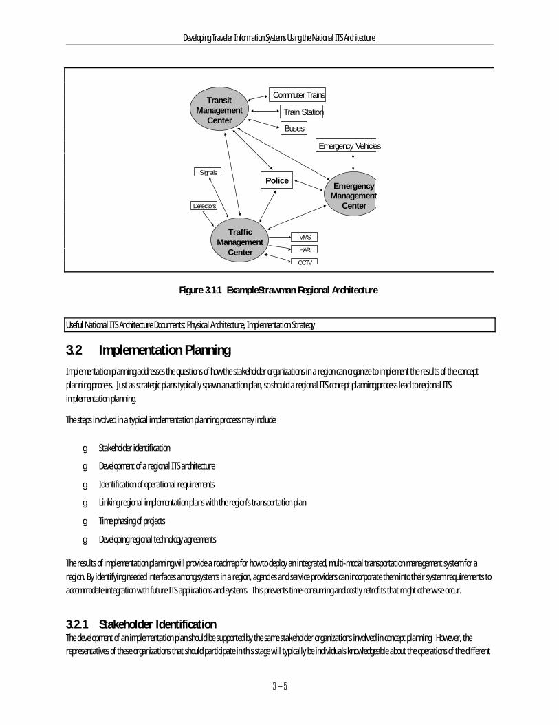
TransitManagement
Center
TrafficManagement
Center
EmergencyManagement
Center
Police
Commuter Trains
Buses
Train Station
VMS
CCTV
HAR
Signals
Detectors
Emergency Vehicles
Developing Traveler Information Systems Using the National ITS Architecture
Figure 3.1-1. ExampleStrawman Regional Architecture
Useful National ITS Architecture Documents: Physical Architecture, Implementation Strategy
3.2 Implementation PlanningImplementation planning addresses the questions of how the stakeholder organizations in a region can organize to implement the results of the conceptplanning process. Just as strategic plans typically spawn an action plan, so should a regional ITS concept planning process lead to regional ITSimplementation planning.
The steps involved in a typical implementation planning process may include:
g Stakeholder identification
g Development of a regional ITS architecture
g Identification of operational requirements
g Linking regional implementation plans with the region’s transportation plan
g Time phasing of projects
g Developing regional technology agreements
The results of implementation planning will provide a roadmap for how to deploy an integrated, multi-modal transportation management system for aregion. By identifying needed interfaces among systems in a region, agencies and service providers can incorporate them into their system requirements toaccommodate integration with future ITS applications and systems. This prevents time-consuming and costly retrofits that might otherwise occur.
3.2.1 Stakeholder IdentificationThe development of an implementation plan should be supported by the same stakeholder organizations involved in concept planning. However, therepresentatives of these organizations that should participate in this stage will typically be individuals knowledgeable about the operations of the different
Developing Traveler Information Systems Using the National ITS Architecture
transportation systems in the region. A structure that involves a steering committee, consisting of senior representatives from stakeholder organizations,and a technical committee, consisting of experienced operations personnel from these organizations, will serve the implementation planning process well.
Active participation during this stage is critical. Support will be needed for inclusion of ITS projects in the region’s capital plan and, most importantly, toachieve buy-in to the operational concepts being formulated.
3.2.2 Development of a Regional ArchitectureA regional architecture is a framework that provides a top-down approach for defining a regional transportation management system. A regionalarchitecture will foster a logical and organized approach to regional ITS implementation and operation.
Regional ITS architecture development should build from the results of concept planning. The architecture should meld existing systems and services withnew systems, services and improvements identified during concept planning. The regional architecture should:
g Identify the different transportation management systems in a region and how they will interact
g Allow multiple agencies, service providers, and users to communicate
g Show the responsibilities of the different organizations and service providers involved in the system
g Identify communications and data flows among participants
g Support development of open systems (i.e., systems with interfaces that use standard or known communications protocols)
g Incorporate the use of existing or planned systems
g Enable synergy among the different systems
g Allow for accommodation of new technologies in the future
g Provide a framework for multiple design choices
g Minimize ambiguity of system design
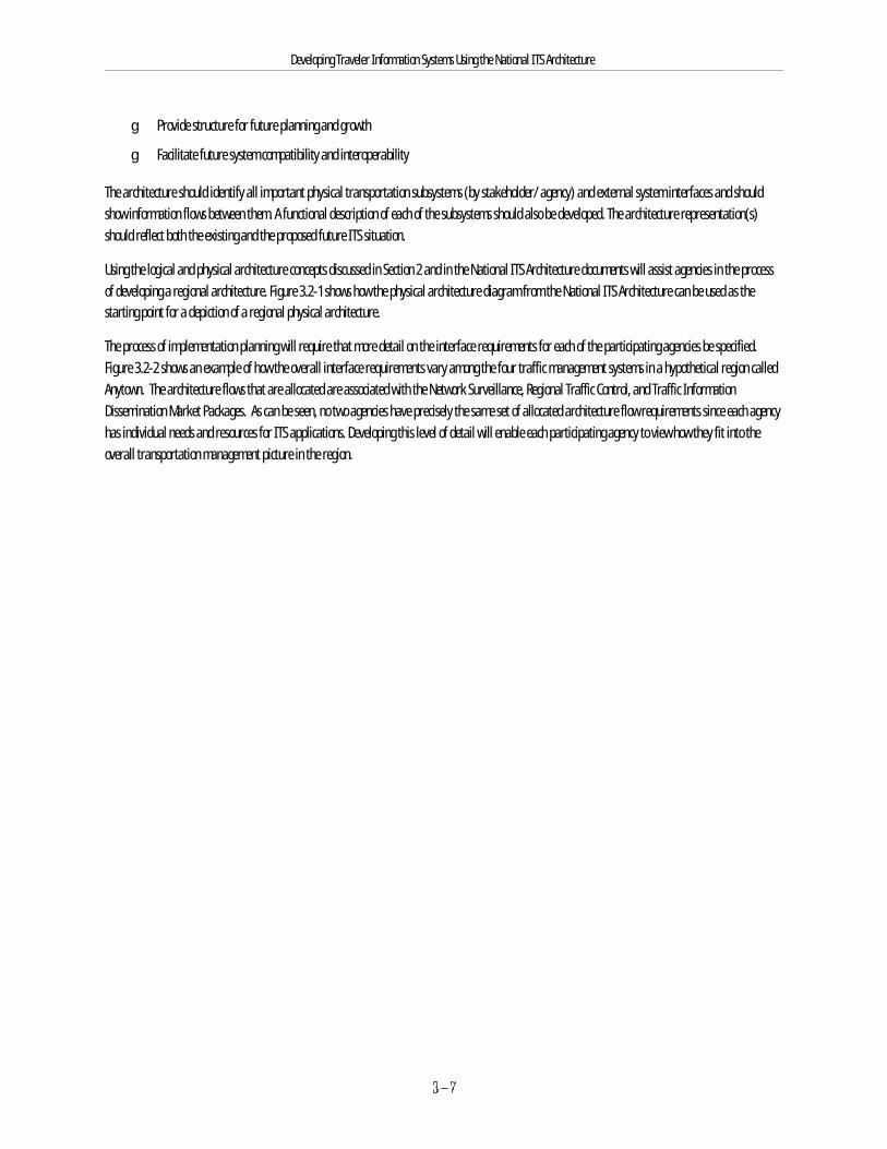
Developing Traveler Information Systems Using the National ITS Architecture
g Provide structure for future planning and growth
g Facilitate future system compatibility and interoperability
The architecture should identify all important physical transportation subsystems (by stakeholder/ agency) and external system interfaces and shouldshow information flows between them. A functional description of each of the subsystems should also be developed. The architecture representation(s)should reflect both the existing and the proposed future ITS situation.
Using the logical and physical architecture concepts discussed in Section 2 and in the National ITS Architecture documents will assist agencies in the processof developing a regional architecture. Figure 3.2-1 shows how the physical architecture diagram from the National ITS Architecture can be used as thestarting point for a depiction of a regional physical architecture.
The process of implementation planning will require that more detail on the interface requirements for each of the participating agencies be specified. Figure 3.2-2 shows an example of how the overall interface requirements vary among the four traffic management systems in a hypothetical region calledAnytown. The architecture flows that are allocated are associated with the Network Surveillance, Regional Traffic Control, and Traffic InformationDissemination Market Packages. As can be seen, no two agencies have precisely the same set of allocated architecture flow requirements since each agencyhas individual needs and resources for ITS applications. Developing this level of detail will enable each participating agency to view how they fit into theoverall transportation management picture in the region.
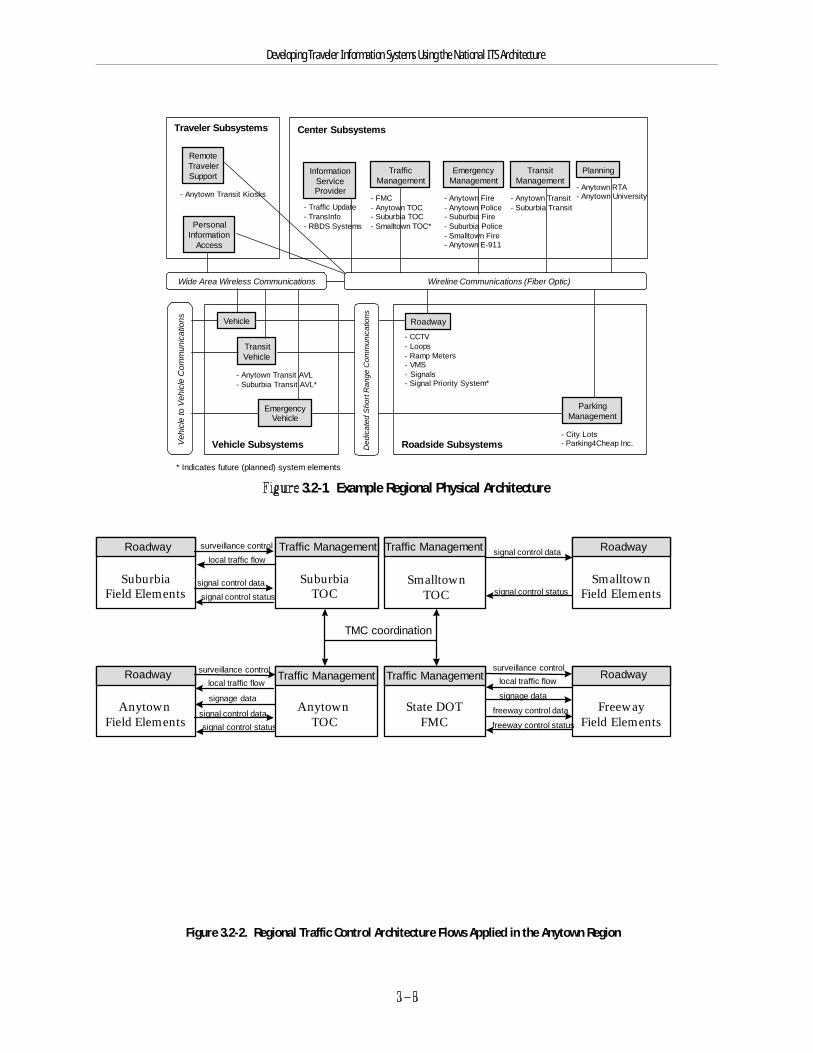
SuburbiaTOC
Traffic Management
SmalltownTOC
Traffic Management
State DOTFMC
Traffic Management
AnytownTOC
Traffic Management
TMC coordination
SuburbiaField Elements
Roadway
AnytownField Elements
Roadway
FreewayField Elements
Roadway
SmalltownField Elements
Roadwaysignal control data
signal control status
freeway control data
freeway control status
surveillance controllocal traffic flow
signage data
signal control data
signal control status
surveillance control
local traffic flow
signal control datasignal control status
surveillance controllocal traffic flow
signage data
Center Subsystems
InformationServiceProvider
- Traffic Update- TransInfo- RBDS Systems
TrafficManagement
- FMC- Anytown TOC- Suburbia TOC- Smalltown TOC*
EmergencyManagement
- Anytown Fire- Anytown Police- Suburbia Fire- Suburbia Police- Smalltown Fire- Anytown E-911
TransitManagement
- Anytown Transit- Suburbia Transit
Planning
- Anytown RTA- Anytown University
Traveler Subsystems
PersonalInformation
Access
RemoteTravelerSupport
- Anytown Transit Kiosks
Vehicle Subsystems
Vehicle
EmergencyVehicle
TransitVehicle
- Anytown Transit AVL- Suburbia Transit AVL*
Roadside Subsystems
Roadway
- CCTV- Loops- Ramp Meters- VMS- Signals- Signal Priority System*
ParkingManagement
- City Lots- Parking4Cheap Inc.
* Indicates future (planned) system elements
Wide Area Wireless Communications Wireline Communications (Fiber Optic)
Veh
icle
to V
ehic
le C
omm
unic
atio
ns
Ded
icat
ed S
hort
Ran
ge C
omm
unic
atio
ns
Developing Traveler Information Systems Using the National ITS Architecture
3.2-1. Example Regional Physical Architecture
Figure 3.2-2. Regional Traffic Control Architecture Flows Applied in the Anytown Region

Developing Traveler Information Systems Using the National ITS Architecture
There are several ways to define the regional architecture at the appropriate level of detail by using the National ITS Architecture information as a startingpoint. One potential method is illustrated below:
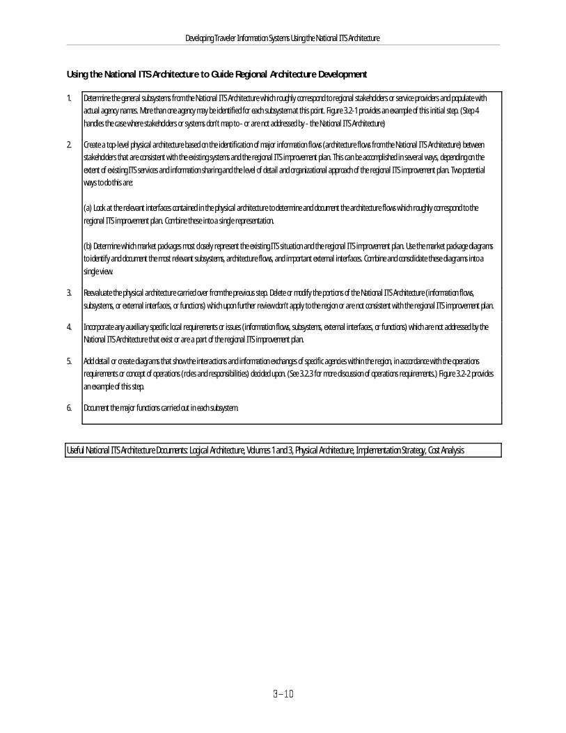
Developing Traveler Information Systems Using the National ITS Architecture
Using the National ITS Architecture to Guide Regional Architecture Development
1. Determine the general subsystems from the National ITS Architecture which roughly correspond to regional stakeholders or service providers and populate withactual agency names. More than one agency may be identified for each subsystem at this point. Figure 3.2-1 provides an example of this initial step. (Step 4handles the case where stakeholders or systems don’t map to - or are not addressed by - the National ITS Architecture)
2. Create a top-level physical architecture based on the identification of major information flows (architecture flows from the National ITS Architecture) betweenstakeholders that are consistent with the existing systems and the regional ITS improvement plan. This can be accomplished in several ways, depending on theextent of existing ITS services and information sharing and the level of detail and organizational approach of the regional ITS improvement plan. Two potentialways to do this are:
(a) Look at the relevant interfaces contained in the physical architecture to determine and document the architecture flows which roughly correspond to theregional ITS improvement plan. Combine these into a single representation.
(b) Determine which market packages most closely represent the existing ITS situation and the regional ITS improvement plan. Use the market package diagramsto identify and document the most relevant subsystems, architecture flows, and important external interfaces. Combine and consolidate these diagrams into asingle view.
3. Reevaluate the physical architecture carried over from the previous step. Delete or modify the portions of the National ITS Architecture (information flows,subsystems, or external interfaces, or functions) which upon further review don’t apply to the region or are not consistent with the regional ITS improvement plan.
4. Incorporate any auxiliary specific local requirements or issues (information flows, subsystems, external interfaces, or functions) which are not addressed by theNational ITS Architecture that exist or are a part of the regional ITS improvement plan.
5. Add detail or create diagrams that show the interactions and information exchanges of specific agencies within the region, in accordance with the operationsrequirements or concept of operations (roles and responsibilities) decided upon. (See 3.2.3 for more discussion of operations requirements.) Figure 3.2-2 providesan example of this step.
6. Document the major functions carried out in each subsystem.
Useful National ITS Architecture Documents: Logical Architecture, Volumes 1 and 3, Physical Architecture, Implementation Strategy, Cost Analysis
Developing Traveler Information Systems Using the National ITS Architecture
3.2.3 Operations RequirementsA critical part of implementation planning is the identification of operational requirements of the planned systems prior to implementation. Developmentof operational requirements requires forward thinking by agencies and service providers. Issues to be addressed may include: the roles and responsibilitiesof the different organizations, development of a concept of operations, identification of funding requirements, interactions during incidents or specialevents, and other operations and maintenance (O&M) considerations. This includes establishing requirements or agreements on information sharing andtraffic device control responsibilities and authority (e.g., deciding if back-up control capability is desired given a loss of power or failure condition). Thesedecisions will be factored into the regional architecture and will also flow-down through ITS deployment projects as they are phased in.
Because many ITS services and strategies involve communication and coordination, this step of planning for operations cannot be overlooked. In the case ofITS, much more is involved than just thinking about how an individual project is to be operated and maintained (by a single agency) after it is constructed.The importance of this planning is that a shared operational concept will be established that will facilitate the future working relationships betweenagencies and service providers.
The concept of regional transportation management can significantly impact the O&M activities of agencies and traveler information service providers. Insome cases, it may increase operations and maintenance costs with the introduction of additional equipment and new technology. Increased costs mayarise from the need for additional staff (or staff training) to operate the systems and additional (and potentially more expensive) maintenance for thesenew systems. The increased investment in operations and maintenance should eventually result in lower user costs due to improved system efficiency.
Identification of O&M requirements is crucial to the success of a project. The development of O&M requirements should involve those most knowledgeableabout these issues, namely the personnel responsible for day-to-day operations and maintenance activities in the different agencies.
The Theory of Operations document can be used to illustrate the sharing of information between subsystems which is relevant in determining the workingrelationships needed between different agencies in order to implement the planned ITS improvements. This type of information can be invaluable indeveloping an overall concept of operations.
Useful National ITS Architecture Document: Theory of Operations
3.2.4 Linkage to the Transportation PlanImplementation planning describes how a regional transportation management system will evolve. Vital to this characterization is how to package thisgradual evolution in terms of projects and funding. The transportation planning process addresses the relative priority of investments in varioustransportation improvements, and it is imperative that relevant information from implementation planning be considered as part that process. Potentialopportunities for leveraging resources, such as adding ITS surveillance and communications infrastructure to facility reconstruction or capacity expansionprojects already planned, should also be explored.
It is important that reasonable estimates of the benefits and costs of specific ITS or transportation management improvements be provided so that theseimprovements can be considered fairly as part of the transportation planning process. The National ITS Architecture development effort producedinformation that can assist that process.
3.2.4.1 BenefitsThe National ITS Architecture also contains material that identifies the likely benefits of integrating market packages and the context where these benefitsmay accrue. Tables showing the likely benefits and context where benefits may accrue for each market package are provided in the Performance andBenefits Study and the Implementation Strategy. Additional resources for ITS benefits information are listed in the References section.
Useful National ITS Architecture Documents: Performance Benefits Study, Implementation Strategy
3.2.4.2 Costs
Developing Traveler Information Systems Using the National ITS Architecture
As a tool to assist in the estimation of costs, the National ITS Architecture documentation contains a series of spreadsheets. Although these should not beused for actual project cost estimation purposes, they are useful to help agencies estimate ballpark costs for planning purposes. Examples of how thesespreadsheets can be used to estimate costs of market packages were provided in Section 2.6.
Useful National ITS Architecture Document: Cost Analysis
Financial Opportunities and ConstraintsLinkage with the capital plan will also require analysis of revenue sources and benefit streams associated with the regional system implementation. Thisstep is where the potential role for public/private partnerships can be considered and weighed.
The physical architecture identifies the interconnections among different transportation subsystems and can assist agencies in determining commoncomponents of systems. This may point out opportunities for sharing resources. Common examples include a communications infrastructure, surveillancedevices, and traveler information systems. An individual agency may be able to reduce costs by sharing these components while minimizing capital andoperating costs.
Useful National ITS Architecture Document: Implementation Strategy
Developing Traveler Information Systems Using the National ITS Architecture
3.2.5 Time PhasingBecause it is unlikely that an entire regional transportation management system will be deployed under a single project, implementation planning shouldalso address prioritization and time phasing of projects. This can be based on a number of criteria such as political issues, cost, amount of impact, anduser visibility. The first components that should be implemented are generally those that:
g Fulfill common functions such as surveillance and communications
g Have the potential to provide early visible benefits to the user such as reliable traveler information
Projects need to be defined in sufficient detail so that benefits and costs can be reasonably estimated. Other elements of the candidate project definitioninclude identification of funding sources, both for capital and recurring operations and maintenance costs, and identification of potential implementationimpediments.
3.2.6 Regional Technology AgreementsA review and assessment of existing and emerging technologies should also be conducted to allow agencies to make good choices among the differenttechnology or deployment options. For example, regional choices on technologies or standards may be required for the telecommunications infrastructure,electronic toll tags, traveler information message formats, signal controllers and interfaces, electronic fare media, and specialized mobile radio systems.
Standards should be identified to provide for interoperability of systems and interchangeability of components. Identification of standards should considerthe current status of ITS standards development activities, and determine how and when these can best be incorporated into the designs of the regionalsystem and individual projects. Establishing regional agreements prior to the issuance of national standards allows for compatibility of systems to berealized sooner at the local level. After national standards are completed for various interfaces, the regional stakeholders are likely to want to eventuallytransition to them (although not all interfaces will be the subject of a national standards activity and regional standardization may be sufficient in somecases). The benefits of using national standards include:
g Compatible and interoperable ITS deployments
g Lower deployment risks, thus stimulating public and private interest in ITS
g Reduced product costs by providing an incentive for multiple suppliers
g Widened markets for suppliers
Developing Traveler Information Systems Using the National ITS Architecture
Standards development is an ongoing process. As agencies and vendors become educated in the implementation of standards, the risk and cost associatedwith system integration should be reduced.
It is sometimes difficult to identify which standards exist and are relevant. The following four-step process is recommended for choosing the appropriatestandards:
1. Develop the regional architecture. Major interfaces and the interface requirements will be defined as part of this step.
2. Review publicly available information on ITS standards to determine the status of standards work that is of interest. (See Section 5 for more detailson where to find this information).
3. Talk to the organizations involved in relevant standards work, such as AASHTO, the Institute of Transportation Engineers, the Society of AutomotiveEngineers, ITS America, and other standards developing organizations.
4. Select the standards that specify each of the major interfaces of interest.
Regional technology agreements may also specify design options to be followed. Tables provided in Section 4.5 of the National ITS ArchitectureImplementation Strategy outline some of the major design options for each of the market packages.
Useful National ITS Architecture Document: Implementation Strategy
3.3 Project DeploymentRegional concept and implementation planning leads to project deployments that fit within a regional transportation management context. Material in theNational ITS Architecture documents also provides agencies with insight on deployment issues, as discussed previously in Section 2.
Project deployment includes detailed design development, procurement, and implementation. Deployment may also be linked with other capitalimprovements, such as including conduit for communication links in roadway re-construction projects. Some helpful project deployment hints are providedin Section 4 of this document.
3.4 EvaluationEvaluation involves measuring and documenting the quantitative and qualitative impacts and benefits that are derived from the proposedimplementations. An ongoing evaluation process should be developed that allows for assessment of progress against the measures of effectivenessdeveloped in the concept planning stage.

Developing Traveler Information Systems Using the National ITS Architecture
It can be very difficult to measure quantitative benefits of many ITS services and improvements because of the uncertain nature of travel demand on anygiven day at any given time. Consequently, qualitative and anecdotal measures can be very useful in illustrating the benefits of many ITS services,especially to agency decision-makers and political representatives.
Useful National ITS Architecture Documents: Performance and Benefits Study, Evaluation Results
Developing Traveler Information Systems Using the National ITS Architecture
4. Lessons Learned / Best PracticesThis section provides some advice from experience on how to best develop and implement advanced traveler information projects from agencies that havedeveloped and implemented ITS projects, or are currently developing or implementing ITS projects. Information contained in this section was derived fromphone interviews, focus group sessions, site visits with agencies, and from the experiences of several consultant organizations. The lessons learned and bestpractices in this section are not intended to be guidance or direction from DOT, but are provided as helpful information.
4.1 Coordination and TeamworkTeamwork and coordination, involving all stakeholders, plus selecting and empowering the right kind of program manager and staff, may very well be yourkey to success.
Coordination and Teamwork may be your Key to Program Success
4.1.1 Regional CoordinationAdvanced traveler information systems must be cooperatively defined and operated in a coordinated manner with other transportation operating agenciesin the same and neighboring jurisdictions, with transit operating authorities, with emergency services providers, and with other entities whose operationsmay be impacted by the operation of the traveler information system. Information sharing with these agencies will be critical to providing informationneeded by travelers in your region. This will call for use of the team approach, involving as many of the stakeholders as possible, in the development of theprogram and individual projects, and a building of trust and working relationships throughout the process, all of which must be carried forward into theactual operation of the system if full benefits to the public are to be realized.
Some key lessons and best practices:
g Include all stakeholders in regional planning and project development phases of ITS programs, including traveler information projects.
g Determine interest of private parties for participation in a traveler information system venture. To ensure fairness, an RFI to determine interestmay be needed. The RFI must query interest, resources, experience and skills covering both the capital acquisition and the operation andmaintenance phases. It should solicit recommendations on characteristics of a possible public-private partnership and should providereasonable bounds on the parameters and expectations of any public-private partnership for the traveler information system.
g Identify an ITS advocate in every key agency as a means to facilitate inter-agency cooperation.
g Foster inter-jurisdictional, inter-agency, and inter-departmental cooperation.
g Try to identify representatives for each major stakeholder at three levels, policy, management, and technical, to participate in those levels ofstakeholder participation. Policy level is needed for top level steering. The management and technical representatives are needed toparticipate in regional planning with a decision making body and technical support committees. This involvement is a key to success of regionalcoordination.
g Address information-sharing issues up front. Partners’ roles and responsibilities need to be clearly defined early in the planning stage.
g The private sector generally needs to see a good potential for a reasonable return on its investment in order to make a long-term commitment.
Developing Traveler Information Systems Using the National ITS Architecture
g Direct focus at current and potential ITS projects rather than at broad ITS themes.
g Keep open lines of communication between all stakeholders during every project phase.
g Involve police and other public safety agencies early in the planning/development process.
g Visit traffic operations centers and traveler information centers in other metropolitan regions to learn about the benefits of ITS projects. Use theinformation gathered to get buy-in from agency decision makers and other stakeholders. Even better, get the decision makers to make thevisits and see the benefits for themselves.
g Address the region’s needs in ITS projects, rather than just deploying technology for technology’s sake.
g Perform public outreach. Emphasize the cost savings, travel time savings and safety improvements benefits of ITS projects to justify ITS to thepublic. Consider outreach activities to educate individuals/agencies on becoming informed consumers of ITS and the benefits that they can bringto transportation systems in their region by means of:
$ Training courses
$ Awareness seminars
$ Workshops
$ One-on-one support
$ Experience sharing
$ Guidance documentation
$ Conference/committee meeting presentations
g Prime considerations when deciding to deploy ITS include the competitive advantage it offers in attracting new business, expanding currentbusiness, or improving the quality of life of a region’s constituents.
g Share the cost of ITS project staff, facilities, and equipment with other ITS stakeholders in your region. The term for this is “Resource Sharing.” The potential benefits to all ITS transportation stakeholders will help encourage this resource sharing.
g Consider the time required to get a Memorandum of Understanding (MOU) developed and signed by all major stakeholders in any planning. Legal issues take a considerable amount of time to resolve.
It is important to appreciate the fact that ITS deployment programs differ in many respects from the traditional highway and street projects which stateand local DOT’s have for many years developed, constructed, and maintained. It follows that the process through which ITS programs are developed mustalso differ from that which has been used in the past.
An open development process, involving all stakeholders, featuring the team approach and leading to the building of consensus, trust, and good workingrelationships, is essential.
Developing Traveler Information Systems Using the National ITS Architecture
This building of consensus, of trust, and of working relationships will all take special effort on the part of those developing the program; it will consumemore staff time and will significantly lengthen project development time. However, it is essential for success. As noted in Sections 1 and 2, use of theNational ITS Architecture tools can help to offset the additional time by savings in staff time and project development time.
4.1.2 The Program Development TeamIt is important that support for ITS traffic management programs be built and maintained as the development process moves along. This support will bevital as various approvals are sought including approval to include the program as a part of the Regional and State Transportation Improvement Plan,approvals for funding, and approvals of individual projects. That support will also be vital as the program moves forward into procurement, throughsystem integration and into actual operation, for highly successful operation will only be achieved through a spirit of cooperation and accommodation,through the coordination of activities of the many operating entities. And the best way to develop and to maintain that support is through a continuedinvolvement of the many stakeholder entities throughout the entire development process. This group of stakeholders can be referred to as the ProgramDevelopment Team.
Develop a broadly based Program Development Team involving as many stakeholders as possible. Keep the Team actively involved throughout thedevelopment of the program; let the Team share in the ownership, the responsibilities, the credit associated with the program.
Developing Traveler Information Systems Using the National ITS Architecture
The role of the team in the development of the program is a critical consideration. Let the team members help in shaping the program; let the teammembers be a part of moving the program forward; let the team members feel a sense of ownership of the program and a responsibility for the program;let the team members share in taking credit for the success of the program.
Some key lessons and best practices:
g Involve the public and private stakeholders throughout the program development process, although staff should become more technical or moredetail oriented as work progresses from concept planning to implementation phases.
g Form separate, but coordinated groups within the Program Development Team to address planning, design, procurement, and operations.
g Carefully define group charters and objectives to heighten productivity and speed results.
g Share project successes and credit for successes.
4.1.3 The Program ManagerMany operating agencies that have successfully deployed and operated ITS programs have attributed much of their success to a common key point, thepresence of a “champion" - a person who fully understands the benefits that can accrue from the program, one who is fully committed to the program, onewho is willing to “go the extra step” to see the program fully deployed and operational, and one who is skilled in convincing others of the value of theprogram.
Some key lessons:
g Ensure continuity of project management.
g Select a well-qualified program manager.
The program manager should have a background in transportation engineering and in traffic management. Training in systems engineering and programmanagement disciplines would be beneficial. He/she should possess both communications and people skills, as well as being computer literate. It isimportant that the “champion” hold a relatively high position within the organization with direct access to a decision-making level of authority, and berespected both within and outside of the organization.
Assign a well-qualified “champion” as Program/Project Manager.Program management continuity will be crucial to program outcome.
Developing Traveler Information Systems Using the National ITS Architecture
4.1.4 Staffing the ProgramSelection of the key staff to support regional transportation planning and to perform the project development work is very important. Some of these mustbe staff that have basic transportation management experience and may be trained to achieve some basic knowledge of National ITS Architectureapplication.
Some key lessons and best practices:
g Address staffing issues early. Prior to the start of an ITS project, ensure that adequate, technically qualified staff are available to work with theproject manager.
g Involve a responsible point of contact in the personnel organization that governs hiring as early as possible.
g Do not underestimate the time requirements involved in the training of public agency staff.
g Involve operations and maintenance personnel in all phases of ITS project planning and deployment so that their roles, responsibilities, andneeds are accurately defined and addressed.
g Include procurement personnel at the beginning of the project. Procurement is as important a phase of the project development as the designand build phases.
g Involve legal staffs early in the process to prevent fatal flaws such as non-conformance with federal, state, and local laws and regulations.
4.2 Project Development ProcessFundamental steps used by transportation agencies in the formulation and implementation of projects involve assessing problems or needs, the search forand selection of a solution, design of the project, and finally, the funding, procurement and implementation. These are the same process steps described inSection 2.
4.2.1 Identification of Needs or ProblemsIn developing any ITS project, one must keep in mind the age-old axiom: Let the problem drive the solution.
Some key lessons and best practices:
g Get ITS buy-in early from upper management (agency decision makers) and mid-level management (project implementers). In particular,apprise them of the needs or problems being addressed
g Gaining consensus on the project definition, users, user needs, and user requirements can take several passes.
g Consider use of focus groups to help determine users, user needs, and technologies involved.
g Do not rush the project requirements phase. A one-month delay early in the project (during the requirements definition phase) may prevent aone-year or several year delay, resulting from incomplete requirements and specifications, in the future.
g Gaining consensus on the project definition, users, user needs, and user requirements can take several passes. Take the time needed to reviewimportant project requirements. Allow the engineering consultant or support contractor at least two reviews (one draft, one final) to develop theuser requirements/equipment specifications. Allow sufficient time for a comprehensive review between draft and final versions of specificationsand requirements.
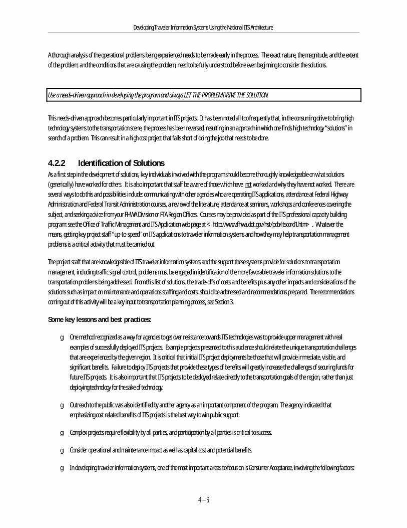
Developing Traveler Information Systems Using the National ITS Architecture
A thorough analysis of the operational problems being experienced needs to be made early in the process. The exact nature, the magnitude, and the extentof the problem; and the conditions that are causing the problem, need to be fully understood before even beginning to consider the solutions.
Use a needs-driven approach in developing the program and always LET THE PROBLEM DRIVE THE SOLUTION.
This needs-driven approach becomes particularly important in ITS projects. It has been noted all too frequently that, in the consuming drive to bring hightechnology systems to the transportation scene, the process has been reversed, resulting in an approach in which one finds high technology “solutions” insearch of a problem. This can result in a high cost project that falls short of doing the job that needs to be done.
4.2.2 Identification of SolutionsAs a first step in the development of solutions, key individuals involved with the program should become thoroughly knowledgeable on what solutions(generically) have worked for others. It is also important that staff be aware of those which have not worked and why they have not worked. There areseveral ways to do this and possibilities include: communicating with other agencies who are operating ITS applications, attendance at Federal HighwayAdministration and Federal Transit Administration courses, a review of the literature, attendance at seminars, workshops and conferences covering thesubject, and seeking advice from your FHWA Division or FTA Region Offices. Courses may be provided as part of the ITS professional capacity buildingprogram: see the Office of Traffic Management and ITS Application web page at <http://www.fhwa.dot.gov/hst/pcb/itscord1.htm>. Whatever themeans, getting key project staff “up-to-speed” on ITS applications to traveler information systems and how they may help transportation managementproblems is a critical activity that must be carried out.
The project staff that are knowledgeable of ITS traveler information systems and the support these systems provide for solutions to transportationmanagement, including traffic signal control, problems must be engaged in identification of the more favorable traveler information solutions to thetransportation problems being addressed. From this list of solutions, the trade-offs of costs and benefits plus any other impacts and considerations of thesolutions such as impact on maintenance and operations staffing and costs, should be addressed and recommendations prepared. The recommendationscoming out of this activity will be a key input to transportation planning process, see Section 3.
Some key lessons and best practices:
g One method recognized as a way for agencies to get over resistance towards ITS technologies was to provide upper management with realexamples of successfully deployed ITS projects. Example projects presented to this audience should relate the unique transportation challengesthat are experienced by the given region. It is critical that initial ITS project deployments be those that will provide immediate, visible, andsignificant benefits. Failure to deploy ITS projects that provide these types of benefits will greatly increase the challenges of securing funds forfuture ITS projects. It is also important that ITS projects to be deployed relate directly to the transportation goals of the region, rather than justdeploying technology for the sake of technology.
g Outreach to the public was also identified by another agency as an important component of the program. The agency indicated thatemphasizing cost related benefits of ITS projects is the best way to win public support.
g Complex projects require flexibility by all parties, and participation by all parties is critical to success.
g Consider operational and maintenance impact as well as capital cost and potential benefits.
g In developing traveler information systems, one of the most important areas to focus on is Consumer Acceptance, involving the following factors:
Developing Traveler Information Systems Using the National ITS Architecture
$ Traveler information must be timely, accurate, relevant, and reliable.
$ Most traveler information consumers would be unwilling to directly pay for traveler information alone, unless it offers a significantimprovement over the traveler information that would be available free-of-charge.
$ Many TIS consumers find traveler information an attractive feature when it is bundled with for-pay services (e.g., stock quotes,weather, sports scores, yellow-pages information, etc.).
$ Travelers are generally more interested in having traveler information for long-distance trips or for travel in unfamiliar areas.
$ Travelers are generally less interested in having traveler information for local or familiar trips. However, travelers are interestedin avoiding any extended delays or other inconveniences.
$ Travelers are generally more interested in having en-route information than in having pre-trip information.
Developing Traveler Information Systems Using the National ITS Architecture
4.2.3 Planning and Design of the SolutionDetailed design of the project should proceed based upon those system characteristics which have been defined in the solution definition and analysis. During the project design phase, as the full implications of using specific hardware/software systems come more into focus, it may be necessary to rethinksome of the decisions made in prior planning. It is fully appropriate—in fact, it should be viewed as a responsibility—to make trade-offs andappropriate changes in the project at this point in the project development process. Some of these trade-offs will be in traveler information systemconfiguration alternatives as described in Section 2.
There are two general approaches which have been taken by agencies in deploying ITS projects, and thus, in the defining of the project to be implemented:(1) the full deployment approach in which the entire system is deployed under one construction contract, one design-build contract, or one system managercontract and (2) a staged project approach in which separate contracts are awarded for the construction of a number of stand-alone subsystems, whichwhen completed, will comprise the comprehensive ITS system.
The “Full Deployment” procurement approach generally requires funding for the deployment of the traveler information system in its entirety under onecontract, but the contract could be a series of separately priced options. This approach will generally produce the entire system as a whole, rather than asthe combination of a series of individually contracted sub-systems. With one contractor having responsibility for the entire system, the integrationproblems should be minimized, thus helping to ensure interoperability. The traveler information system must be integrated with a number of othersystems in the region in order to establish the necessary information base.
Under “Staged,” “Incremental,” or “Evolutionary” approach, a series of projects, each consisting of a stand-alone subsystem capable of deliveringbenefits, are constructed under separate contracts over a period of time. Each subsequent sub-system is integrated with those which have preceded it,evolving into the comprehensive system. For example some of the information sources, the information analysis, and the traveler information distributionmethods could be phased in over time and the implementation of some value added features could also be phased in over time. One of the major areasthat must be addressed up front is definition of the communications facility or capability that will handle the long-term needs of the traveler informationsystem. The greatest risk of the staged project approach has to do with those problems associated with the integration of new systems with those which arealready on-line, and with the assignment for accountability of that function. When the traveler information system can’t be integrated with a vitaltransportation information source, and one or both systems have to be modified, the costs may increase substantially. However, there may be advantages. Available funding levels may be less of a problem, as capabilities to match available funding levels can be spaced out over a period of time. There is theopportunity to select “winners,” those projects on which there is a high probability of success, as early projects with very visible benefits. However, theevolutionary approach delays the full benefits needed to attract and build a sound customer base for the traveler information services and products.
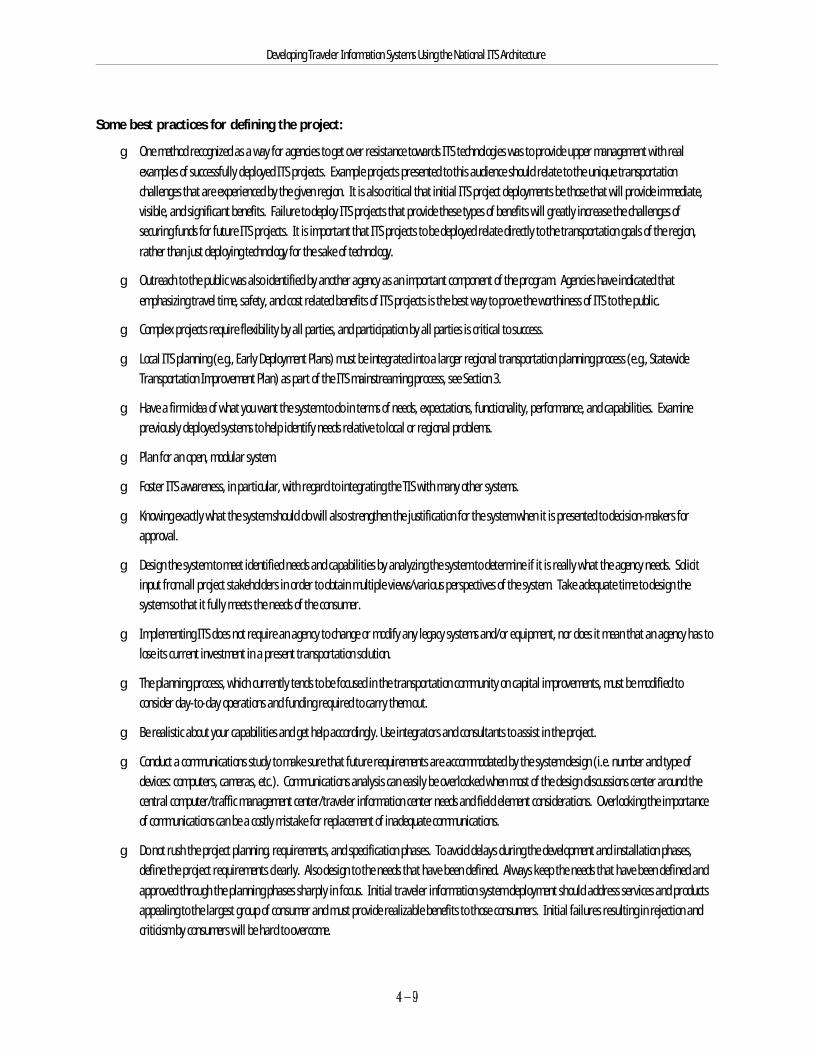
Developing Traveler Information Systems Using the National ITS Architecture
Some best practices for defining the project:
g One method recognized as a way for agencies to get over resistance towards ITS technologies was to provide upper management with realexamples of successfully deployed ITS projects. Example projects presented to this audience should relate to the unique transportationchallenges that are experienced by the given region. It is also critical that initial ITS project deployments be those that will provide immediate,visible, and significant benefits. Failure to deploy ITS projects that provide these types of benefits will greatly increase the challenges ofsecuring funds for future ITS projects. It is important that ITS projects to be deployed relate directly to the transportation goals of the region,rather than just deploying technology for the sake of technology.
g Outreach to the public was also identified by another agency as an important component of the program. Agencies have indicated thatemphasizing travel time, safety, and cost related benefits of ITS projects is the best way to prove the worthiness of ITS to the public.
g Complex projects require flexibility by all parties, and participation by all parties is critical to success.
g Local ITS planning (e.g., Early Deployment Plans) must be integrated into a larger regional transportation planning process (e.g., StatewideTransportation Improvement Plan) as part of the ITS mainstreaming process, see Section 3.
g Have a firm idea of what you want the system to do in terms of needs, expectations, functionality, performance, and capabilities. Examinepreviously deployed systems to help identify needs relative to local or regional problems.
g Plan for an open, modular system.
g Foster ITS awareness, in particular, with regard to integrating the TIS with many other systems.
g Knowing exactly what the system should do will also strengthen the justification for the system when it is presented to decision-makers forapproval.
g Design the system to meet identified needs and capabilities by analyzing the system to determine if it is really what the agency needs. Solicitinput from all project stakeholders in order to obtain multiple views/various perspectives of the system. Take adequate time to design thesystem so that it fully meets the needs of the consumer.
g Implementing ITS does not require an agency to change or modify any legacy systems and/or equipment, nor does it mean that an agency has tolose its current investment in a present transportation solution.
g The planning process, which currently tends to be focused in the transportation community on capital improvements, must be modified toconsider day-to-day operations and funding required to carry them out.
g Be realistic about your capabilities and get help accordingly. Use integrators and consultants to assist in the project.
g Conduct a communications study to make sure that future requirements are accommodated by the system design (i.e. number and type ofdevices: computers, cameras, etc.). Communications analysis can easily be overlooked when most of the design discussions center around thecentral computer/traffic management center/traveler information center needs and field element considerations. Overlooking the importanceof communications can be a costly mistake for replacement of inadequate communications.
g Do not rush the project planning, requirements, and specification phases. To avoid delays during the development and installation phases,define the project requirements clearly. Also design to the needs that have been defined. Always keep the needs that have been defined andapproved through the planning phases sharply in focus. Initial traveler information system deployment should address services and productsappealing to the largest group of consumer and must provide realizable benefits to those consumers. Initial failures resulting in rejection andcriticism by consumers will be hard to overcome.
Developing Traveler Information Systems Using the National ITS Architecture
g In order to ensure the reliability and functionality of enabling technologies, it is recommended that the agencies developing ITS applications fullyinvestigate previous applications of candidate technologies in real world applications. These investigations should include discussions and/orsite visits to agencies that have previously deployed the technologies. It is also important that these investigations be carried out independentlyof any vendors.
g Evaluation Design:
$ Demonstrable benefits are critical to participants in order to demonstrate their return-on-investment for both Public and PrivatePartners. This could be essential for obtaining support for future related projects. Measurable benefits to the traveler arenecessary for growing the traveler information customer base. In most cases, the customer perception of being benefited throughavoidance of significant delay may be valuable, but difficult to quantify.
$ The evaluation process should be initiated during the project planning phase. Evaluation contractors should be brought on-boardearly.
$ In order to be effective, the evaluator must be given the opportunity to influence the system design so that the system willaccommodate the measurements needed to conduct the requisite analysis. Benefits analysis usually must involve before and afterdata.
$ The evaluator should be under direct contract to the lead agency or partner.
$ When reasonable, ensure that national goals as well as local goals and objectives are evaluated.
Developing Traveler Information Systems Using the National ITS Architecture
g Avoid closed proprietary systems (whenever possible). Instead, use an open systems architecture to:
$ Promote interoperability.
$ Promote modularity.
$ Support one product from multiple vendors.
$ Accommodate diverse geographic settings and variations in local environments.
g Use standards (whenever possible) to promote interoperability and prevent obsolescence.
g Use the National ITS Architecture as a design framework to:
$ Coordinate design with other ITS systems.
$ Accommodate future applications/interfaces between TIS and other systems/subsystems.
g Define functional requirements and performance standards for all system components.
g Vendors should furnish all of the necessary system documentation including detailed functional requirements; system design reports; systemconfiguration diagrams; interface specifications; product/hardware/software documentation; test specifications and test procedures; andoperator manuals, user guidelines, and Standard Operating Procedures (SOPs).
g Material presented on an in-vehicle display should be consistent with the corresponding material displayed on road signs.
g Build only what you can realistically maintain. During the design and build phases of the project, make sure you keep an eye on realisticmaintainability/reliability expectations. The system’s final state should be defined and the system developers should stay focused on therequirements of the final product, not just the next deliverable.
It is essential that ITS systems be designed to do the job needed to solve the local and regional transportation problem, to provide for compatibility ofoperation with a variety of other systems being operated by other transportation-related entities, to provide for interoperability with those other systems,and to be designed so that they can be reasonably modified and/or expanded in the future.
4.2.4 Funding, Procurement and Implementation
4.2.4.1 The ScheduleThe schedule must be well thought out, be realistic, clearly show task inter-relationships, and be in a form which can be easily communicated andunderstood. It must have the commitment of the project team. It should be used on a continuing basis as one of the most powerful tools in managing theproject. All reasonable steps should be taken by all parties to adhere to the schedule. It should be up-dated and adjusted when slippages do occur.
Developing Traveler Information Systems Using the National ITS Architecture
Some key lessons and best practices:
g Do not adopt an optimistic schedule.
g Define frequent and realistic milestones to use in assessing progress against the schedule.
g Unambiguously define all milestones.
g Define each milestone so that reaching it is clearly identifiable.
g Make reasonable efforts to keep the project on schedule. However, never cut schedules for reviews of design documentation, for preliminaryand final design review presentations by the contractor, for system integration, or for thorough testing, in the factory, at the first field site andat every field site. When needed to preserve these critical activities, extend the schedule.
4.2.4.2 Funding the ProgramObtaining funding for the project is one of the most critical responsibilities of the project manager and his/her higher management. It is essential thathe/she “think funding” from the inception of the program, seeking out every opportunity to secure funding from a variety of sources for the variouselements of the overall program. One goal should be to secure funding from a number of sources—the more the better—for the commitment of fundingassures that there is a support for the overall program from that funding source. For traveler information systems projects, it is important to furtherleverage public funds with private party funds for capital, operating and maintenance costs.
Some key lessons and best practices:
g Commitment of capital funding as well as operations and maintenance funding from private sources, through public/private partnerships orother arrangements, thus leveraging the public funds, further strengthens any ITS program insofar as competing for funds from public sources. Also, the higher the federal match and the private partner investment, the more likely the project will be included in the capital improvementsprogram.
g Share your funding experiences for design, construction, operations and maintenance.
g Share your experience using Federal-aid funding for operations cost and how to work with your metropolitan planning organizations (MPOs) toget their support.
g Shortages of funding are common, as a result of stiff project competition (primarily traditional non-ITS projects); budget cuts; capital vs.operations and maintenance budgets; and operations and maintenance cost increases.
g Maintain a realistic assessment of funding.
Develop a broad-based funding package, with funding coming from as many sources as possible.
Developing Traveler Information Systems Using the National ITS Architecture
It is important that the project get into the programming process as early as possible in the project development phase, in order that funding will, in fact,be available at the time the project is ready for construction. While many ITS projects in the past were funded without going through the TransportationImprovement Planning (TIP) process (since they were funded as under a research or operational test environment), steps should be taken to have theproject included in the TIP, in order to ensure eligibility for funding. Projects need to be entered into the programming stream to obtain funding from othersources.
Identify funding sources, and carry projects into the programming processes at the earliest possible stage of project development. Secure approvals forstaffing levels to operate systems and for funding to cover other on-going operating and maintenance cost.
4.2.4.3 Agency / Contractor Interaction and Other IssuesMany agencies strive to keep the contractor “at a distance” which would work well in a perfect world where requirements are perfectly described andunderstood and where the contractor’s design is perfectly described and understood. Lacking this perfect world, developing a cooperative workingrelationship between agency and contractor is most likely to yield a system that meets agency requirements. In such a relationship, it is appropriate thatrules be established to limit information going to the contractor from agency staff and other agency representatives to “interpretations of therequirements,” and within the contract scope. Included must be the admonition that only through contracting officer direction may the scope of thecontract be changed.
Some key lessons and best practices:
g Don’t simply take a vendor’s or contractor’s advice or word on the capabilities of a system or piece of equipment. Ask them: “Has the(system/software/equipment) been used in a traveler information system application before? Has the (system/software/equipment) been usedto perform this (task/function) before?” Be sure to obtain references as to where these applications were and what agencies were involved andthen talk to those references.
g Make sure the company from which you are purchasing services or equipment from is financially sound. Check business and technicalreferences. Talk to others in the field who have done what you are planning to do.
g Maintain focus on the system’s final configuration definition. Keep the system developer’s focus on the requirements of the final product, notjust the next deliverable.
g Take the time needed to review important project requirements. For larger projects, allow the contractor/equipment vendors at least two passes(one draft, one final) to develop the user requirements and the equipment and software specifications. For smaller projects, one pass maysuffice. Arrange in the contractor’s work statement for audio/visual presentations of the draft and final designs to agency staff, plus otheragency representatives and project stakeholders. This is helpful in identifying requirements misinterpretations.
Developing Traveler Information Systems Using the National ITS Architecture
g Allow sufficient time for a comprehensive review of draft and final versions of test specifications and test procedures.
g When significant amounts of software development are involved, arrange to have one or two key staff and expert software engineerrepresentatives sit in on the contractor’s internal software design walk throughs, since these cover how the system will work in some detail andmay highlight misinterpretations.
4.2.4.4 Managing the ProgramThere are many lessons that have been learned on ITS projects and on other kinds of projects, including those from program management efforts of othercivil and defense agencies. Although most ITS projects are much smaller in scope than most defense projects, many of the lessons apply. Most of thesystem engineering tools that other agencies have used are beyond the scope of this document, but guidance on courses or seminars that describeapplication of system engineering tools to ITS projects is available from the FHWA Division or FTA Region Offices.
Some key lessons and best practices:
g Look for success stories in the ITS field prior to starting your ITS project. Learn from projects related to what you are trying to do—what arethe benefits? Was it cost effective? Also check out the benefits reference documents. This will help you to support your project as it develops.
g Provide upper management and decision makers with real examples of successfully deployed ITS projects. This is a way for agencies toovercome resistance to ITS technologies. Example projects should relate to the unique transportation problems in your region.
g Use the design/build process to get systems operating early whenever appropriate. However, be cautious about using a design/build processthat involves any significant amount of development, see also Section 4.3.2 on Selection of the Contracting Approach. It is also important toseparate the design aspects of the project from the build by thorough review of all design aspects of the project as milestones separating thephases. The review time required for a design should not be underestimated.
g Manage project and system expectations. They need to be realistic and achievable with available funding, time (schedule), and staffing.
g Emphasize consensus and coordination as keys to project success.
g Exceeding the costs estimated for software development is highly probable and a major problem in the industry. Cost overruns are common inITS projects. Agencies need to be prepared for these overruns by developing contingency plans. Contractors can only base realistic softwaredevelopment cost on accurate, detailed requirements specifications.
g Use technical proposals and preliminary and final design reviews to achieve compatible agency and contractor interpretations of requirementsas early as possible. Differing interpretations will yield false starts and wasted effort, time and money.
g Share your successes, and share credit for your successes.
g Schedule project activities (e.g., meetings, teleconferences, etc.) with a great deal of flexibility to ensure stakeholder participation/consensus.
g As unanticipated problems occur, the schedule slips, staff once available become unavailable, budgets appear inadequate—a few words ofadvice:
$ Take a step back and take a look at the big picture to reassess where the project stands. Back away from trying to cope withnumerous details and topics with which you may not be completely familiar.

Developing Traveler Information Systems Using the National ITS Architecture
$ Revisit your project plan. To help bring the project back on track, all parties involved will need to be honest about achieving projectexpectations, and about assessing what can be realistically accomplished with available resources.
$ Be reasonable about deliverables, schedule, scope, and requirements.
$ Focus on the system features that will bring the most benefit. Consider dropping less significant aspects of the project unlessneeded as basic building blocks for more desirable features.
$ Focus on what has been accomplished so far, rather than on how much is left to do. Other staff may need reassurance. Positivemotivation can be very helpful to your team, and help you get through a crisis.
$ Create an environment that encourages solutions, rather than focusing on problems. Establish an environment in which youragency, the equipment vendors, and other contractors can cooperate to complete the project successfully.
g Document control is very important. Track and control project documentation. Use a numbering scheme, such as PROJECT-TASK-YEAR-DOCUMENT NUMBER-REVISION LEVEL.
g It is critical that initial ITS project deployments provide immediate, visible and significant benefits. Failure to do this will make it harder tosecure funds for future ITS projects.
g Learn and share lessons from all projects. Create an environment where engineers from different backgrounds and projects have anopportunity to share their experiences with each other—begin a “brown bag” lunch program or project/technologies discussion group.
g Establish well-defined roles and responsibilities for all staff members early on. Match the project assignment to the appropriate staff. Determine staff expertise required and methods to retain key individuals/positions.
g Follow successful management techniques used elsewhere on projects of a similar nature.
Developing Traveler Information Systems Using the National ITS Architecture
4.2.4.5 System Integration and TestingBeing very thorough in the integration and testing of your system will be as important, perhaps more important, than anything else you do on the project,including writing complete and accurate specifications. System integration and testing will be needed at different levels. During development, integrationand test will be accomplished the first time and must be very thorough, testing against every requirement. Keep in mind that each requirement must bedefined such that it is verifiable, otherwise it is a useless requirement. This testing may include rigorous testing, analyses and demonstrations. Afterpassing development testing verifying that each requirement is met, acceptance testing in the field need not test every requirement, but must ensure thatthe deliverable is acceptable.
Some key lessons and best practices:
g Integration of existing/working technologies is hard enough without introducing new and untried technologies.
g Systems can be built incrementally, however, any necessary communications equipment needs to be in place for integration with prior andfuture increments.
g Integration needs to be done in a controlled environment (e.g. design or factory acceptance tests) to isolate problems and system bugs. Interfaces with some devices may have to be emulated for early integration efforts.
g It is important that all requirements be verified on the completed system wherever possible, since the integration of units and subsystems intothe full system may produce interactions that disable or change some functionality or cause some performance requirement to no longer besatisfied.
g Do integration in steps − add one component at a time. Do not wait until the end of the project to integrate all of the system components, sinceit would be extremely difficult to isolate problems. Integration and testing can easily take 30-40% of the time and resources of a project.
g Take the time to thoroughly debug and test a few units in the field prior to deploying a large number in the field. Require contractors tosuccessfully conduct acceptance tests on each major deliverable, witnessed by the agency’s representatives prior to acceptance by the agency.
g When changes are made in some area of a design, keep in mind that there may be both desirable and undesirable consequences of the changethat may ripple through the design, and testing must ensure that the device, unit, or subsystem still functions properly after the change.
g Use trained agency staff in hands-on roles for operational and maintenance testing, particularly final development test in the factory and finalacceptance test at the few field sites. This must be written into the contract since contractors will otherwise not allow non-contractor staff totouch their equipment. Although the contractor may resist giving the agency staff any hands-on involvement prior to final acceptance, if thoseagency staff can break the system by using it, this must be found out before the contractor receives final payment and walks away.
4.2.5 Operations and MaintenanceAs mentioned in several places above, the importance of operations and maintenance can not be over stressed. Operations and maintenance must beincluded in all phases of any ITS project from planning through design, integration and test, and into field implementation and beyond.
Some key lessons and best practices:
g Involve operations and maintenance personnel in requirements reviews, specification reviews and in preliminary and final system designreviews to keep them involved and to get their buy-in to the system.
Developing Traveler Information Systems Using the National ITS Architecture
g Secure/budget adequate operations and maintenance resources (e.g., staff, funding, time/schedule, etc.).
g Train system operators and maintenance personnel on the appropriate system operations and maintenance aspects in order to ensure successfulsystem operations.
g Perform operational and maintenance training early. Use those trained staff in hands-on roles for operational and maintenance testing,particularly in final acceptance tests. This is an important training experience for those staff.
4.3 Procurement and Contracting
Transportation agencies face many impediments in the procurement and contracting of developing projects, as procedures, controls and measures whichhave been put into place over the years for construction projects have had to be accommodated. However, there is some relief for these impediments. Thissection sheds some light on the more common problems that have been experienced, and some of the solutions that have been developed.
4.3.1 Autonomy in the Procurement ProcessIn some agencies, it has been the practice to clearly separate the procurement function from those who will use the goods or services procured. Thisautonomy in the procurement process is seen as providing certain assurances relative to the proper expenditure and management of public funds. However, because of the technical complexity of most ITS systems, and the need for these systems to be interoperable, technical and operational advice iscritical in making wise procurement decisions.
Transportation management agencies should balance the need for autonomy in procurement with the obvious need for those with the technical andoperational knowledge of ITS systems to participate in the procurement process. A sufficient degree of autonomy can be maintained while still involvingtechnical staff, by adopting a team approach to procurement, which would include technical advisers and budget and procurement personnel. By bringingboth sides together, each can gain a better understanding of the knowledge each brings to the discussions.
It is crucial in ITS procurements that technical/operational, budgetary, and management elements be involved in proposal evaluation with each presentingits findings to a selection board. Bids from contractors that are not judged responsible companies able to perform or with technical proposals that are nottechnically acceptable should be rejected.
This will allow the technical advisers to make recommendations on the extent to which or even whether the types of technology and systems available willmeet agency needs, and the procurement specialists to outline budget, financial, and procurement restrictions that may impact how the type of technologyor service is to be procured.
4.3.2 Selection of the Contracting ApproachThere are several possible public-private partnership models that might be chosen for the traveler information system procurement and of course thiswould influence the contracting approach to be used. In some models, the private partner might handle the contracting. In other models, the major publicagency might do the contracting for traveler information system development and deployment. There are some excellent courses that have been developedthat touch on this, including; Innovative Finance Strategies for Deploying ITS and ITS Public/Private Partnership (see the references for furtherinformation). It has been demonstrated on a few major projects that having the private partner handle the procurement can significantly speed up projectdeployment. The material below is applicable to public agency procurement.
Developing Traveler Information Systems Using the National ITS Architecture
The selection of a particular contracting arrangement for deploying ITS systems may be critical to the successful deployment of an ITS system, and,ultimately, to it’s successful operation. Three contracting approaches have been used by public agencies for the deployment of ITS transportation systems. These three are discussed below. The use of each has met with varying degrees of success. See also a paper on innovative contracting for ITS projects[Innovative Contracting Practices for ITS, April 1997] and another paper on procurement regulations and contracting options [FHWA Federal-Aid ITSProcurement Regulations and Contracting Options, August 1997] both available on the FHWA ITS web page. This contracting options paper, available inhardcopy from NTIS or electronically from the Turner Fairbanks Highway Research Center web page, is a valuable resource. Figure 1 of that paperidentifies four basic contract types, their possible application, and their approval requirements. Three of those approaches are discussed below.
Conventional PS&E/Contract Bid Approach
In this approach, the designer develops specifications for both software and hardware, and these are included in the PS&E (Procurement Specification andEstimate) package and RFP (Request for Proposal). A contract for the construction, hardware, and software to deploy the system is then let in the mannerof a conventional highway contract. This contracting approach may be appropriate for procurement and contractor installation of field devices andhardware. However, for design, development, integration and system engineering services, this approach has resulted in some problems in the past.Hardware/software incompatibilities have arisen, and these systems have not performed as anticipated. In some cases, major modifications in hardwareand/or software was called for in order to produce working systems. Resolution of issues relative to the accountability for these deficiencies, and of theresponsibility for the development and deployment of corrective measures have proven to be particularly difficult in many cases. In general, this approachdoes not work well for technology acquisition.
System Manager Approach
Under the system manager approach, a consultant is engaged to develop the software and hardware specifications for the ITS system, and to produce aPS&E for the project. Contracting for the system manager’s services falls under the Engineering and Design Services contract category which includesservices like program and construction management, engineering, design, and surveying. Using the PS&E developed by the system manager, a contract forfurnishing and installing hardware, and for other required items is let, using traditional contracting procedures as in the contract-bid category ofcontracting. Here, a key difference comes into play: the software/hardware consultant’s responsibilities carry into the deployment phase of the systemunder this approach. The consultant is responsible for the final design and development of software and for integrating it with the hardware as it isinstalled, and for providing documentation and training to operating staff in the use of the integrated system. Several advantages to the system managerapproach have been noted:
g The process includes competitive bidding, with all of its benefits, for the furnishing and installing of hardware, and for facility and electricalconstruction.
g Access to those developing the system software, and agency control over system development, are greatly facilitated. If the control systemhardware is included with the software bid, a hardware contractor who does not produce software could win the bid. The hardware companywill subcontract the software to a software company. The client then has very limited access and control over the system development and maynot be able to ensure that the system meets its requirements.
g The system manager approach gives the flexibility to incorporate the latest technologies into the system, as well as to provide integration withother ITS systems including traffic control systems which may be operating on local and regional roadway networks. It is important to avoid thelow-bid syndrome, where the software is designed to do the absolute minimum required to meet the specifications rather than take advantageof the latest thinking and processes in a rapidly evolving technological market.
Design/Build Approach

Developing Traveler Information Systems Using the National ITS Architecture
In this approach, a contractor is selected based on the contractor’s qualifications and an assessment of the contractor’s ability to perform followed bycompetitive negotiation. This single competitive contract is then awarded for design and construction of the project. This differs from the design-bid-buildapproach in that design-bid-build uses two sequential competitively awarded contracts, the first for design and the second for construction. Thedesign/build approach traditionally combines the procurement procedures employed with the traditional engineering and design services contracts withthose used in the traditional construction contracts, and thus embodies characteristics of both. These procedures may include pre-qualification, competitivesealed bidding, and award criteria based on price and other factors. It may be useful to require separate detailed technical proposals and cost/businessproposals and evaluate technical proposals first. Then the predetermined selection criteria would include evaluation of the offerors’ technical proposalsthat have been found to be acceptable, by a predefined set of criteria. This approach will provide indications of the each offeror’s skills, understanding,and approach to the project. The negative is that the project requirements must be spelled out in the RFP so that the offerors can respond to them.
The design/build approach relies on the contractor to develop a design and then to build the project. The agency’s role is to monitor the contractor’s work. Generally this has worked for roadways and structures. However, it may have significant problems when applied to technology acquisition depending oncontract type (e.g., fixed price or cost type) and the nature of the relationship between the agency and contractor. If the agency has a hands-off approachto contract management, the contractor may design and build much of the system based on incorrect interpretations of requirements. Some of the workmay be found to be unacceptable. Partnering of the agency and contractor so that requirements are properly interpreted and the design is reviewed byagency representatives and found acceptable, before construction and implementation work proceeds, can lead to positive results. However, if the entirecontract is a fixed price type, the contractor has an incentive to interpret requirements, produce a design, and build the system to minimize thecontractor’s cost. A way to address this issue is to have the agency more directly involved in the clarification of requirements during contract performance.This, in turn, may increase the contract scope. Also, if the contractor subcontracts the software to be designed and built by another contractor, there maybe lack of visibility into the software development process. This is likely to result in a lack of agency knowledge and control of the software and anunacceptable system.
FHWA established Special Experimental Project No. 14 , Innovative Contracting Practices (SEP-14) to enable agencies to implement and evaluate innovativecontracting practices that maintain competition advantages while striving for quality and timeliness. Included under SEP-14 are Experimental Design-Build and Non-Experimental Cost-Plus-Time contracting innovations. Federal-aid funds may be used in design-build contracts when awarded withcompetitive bidding procedures and subject to FHWA approval under SEP-14.
Give full consideration to the use of the System Manager Approach when deciding upon the contracting arrangement to use.
4.3.3 Procurement Rules and RegulationsAlthough federal legislative requirements mandating the use of low bid procurements have been relaxed in recent years, many states still require its use forprocuring many services and equipment. In addition, it is still the preferred method for acquiring construction services in the public sector. But there can beproblems with accepting low bids for ITS systems and devices.
Some key lessons about low bids:
g An important problem with low bids: the equipment and software are frequently designed to do the absolute minimum required to meet thespecifications rather than take advantage of the latest advances in technology.
g The design of the system provided by a low bidder may have many misinterpretations of the requirements with major cost increases for thecorrections thus allowing the bidder to bid very low, with later scope increases. Specified requirements must be accurate and thorough. Eventhen a low bidding contractor will find ways to reduce costs by not meeting requirements or by misinterpreting requirements.
Developing Traveler Information Systems Using the National ITS Architecture
g Often systems that are low bid have limited expansion capabilities. These limitations are frequently not discovered until control elements areexpanded or modified at a later date.
g As upgrades to the system hardware and software are needed in later years, there may be design problems that require very expensive redesignand expansion of the system.
Traditional transportation procurement approaches will usually not provide the flexibility necessary for acquiring ITS projects. In an effort to providegreater flexibility to state and local governments in their procurement procedures, the U.S. Office of Management and Budget established the Common Rulegoverning grants administration. The rule provides that states will spend and account for grant funds according to their own laws and procedures. Whilesome procurement methods have very specific federal rules to be followed (particularly procurements for architect/engineering services for constructionprojects), there is considerable flexibility in most other procurement models.
Project team members should work together to select the most appropriate procurement mechanism, contracting lead agency, and contracting approach forany particular project. In selecting the procurement and contracting approach, the most favorable alternatives need to be compared side-by-side listingall pros and cons of each. Decisions relative to project team members, as well as procurement-related issues, need to be made early in the projectdevelopment process since many facets of the project will be impacted by these decisions.
4.3.4 Procuring SoftwareProcuring software has always been complex and care must be exercised to control the risks inherent in this activity. There are many important topics tobe informed of on software acquisition. As of 1998, U.S. DOT is preparing an ITS software acquisition guidance document. Some of the key topics coveredinclude the following, all of which are important:
g Acquisition approaches
g Consideration of commercial-off-the-shelf (COTS) software with its pros and cons
g Importance of requirements
g Acceptance criteria
g Intellectual property rights
g Schedule issues
The document is built around people, management, and system themes that encourage partnering between the agency and software contractor to ensureunderstanding and translation of requirements into software.
Using “off-the-shelf” software packages and systems are often touted as low risk, but may or may not reduce risk. Making major changes to an existingsoftware system may be quite difficult. Nevertheless, agencies should familiarize themselves with the different product offerings before issuingprocurement documents since it may be possible to meet requirements while saving time and money. A key point - careful consideration should be given torequirements that might involve extensive new software development or extensive product offering changes because of the risk implications.
Some further considerations involve right of use for agency funded copy-righted software and source code and other supporting software and tools toensure ability of continued use of their investment.
g New software, which is developed for the project needs to be copyrighted, and ownership details need to be worked out ahead of time with thecontractor. These arrangements need to be made prior to start of the software development phase. It is important for agencies that are
Developing Traveler Information Systems Using the National ITS Architecture
implementing traveler information systems to have rights over the software that is delivered. Such rights would allow the agency to use, amendand expand the TIS without reliance on the vendor.
g The rapid rate of change in current technologies leads to many companies either changing the business they are in, being absorbed by others ifsuccessful, or going out of business when unsuccessful. Agencies need to protect themselves and their investment in the software. They need toensure that all source code, development tools, operating systems and associated software are delivered. In addition, it is wise to make precisecopies of the installed system to ensure that not only the code but also the correctly configured version of the operating systems are archived. Vendors often provide a basic platform that requires modification for each specific client. Vendors are likely to require some limitations on thedelivery of all their source code. Such limitations can be:
$ Geographic - The system cannot be used outside a specific area.
$ Temporal - The product is licensed for some duration.
$ Functional - The product is only warranted until recompiled.
These limitations need to be the subject of contractual discussions between the agency and the vendor.
Developing Traveler Information Systems Using the National ITS Architecture
4.3.5 Procuring TelecommunicationsJust as transportation is the backbone of our communities, serving to move people and goods from point to point, telecommunications is the backbone ofITS, serving to move information among detectors, transportation management centers, and field devices. Telecommunications is vital and expensive. Anew telecommunications system can be the highest cost item in an ITS deployment project. A telecommunications analysis including the three steps belowshould support telecommunications decisions:
g Requirements Definition
g Definition of Network Options
g Cost AnalysisThe Requirements Definition step is the most important. Good decisions can only be made if care is taken during this step of the analysis. The product ofrequirements definition is a reasonable estimate of how much information needs to be moved from point to point throughout the system in its future fullydeployed state. To do this, a rigorous estimation process that focuses on needs rather than possibilities must be followed. This must be supported by anunderstanding of the types of devices to be installed, where they will be, how many there will be, message sizes and frequencies, etc. Also, the region’splan for locating and communicating among transportation management centers must be understood. Perhaps the most fundamental question inrequirements definition is whether the telecommunications system will serve the needs of a single agency, multiple transportation agencies in a region, ormultiple government agencies within a jurisdiction or region. The latter two raise issues about ownership and cost participation, but should be consideredfrom a good public policy perspective. The video requirement should be carefully considered. Among the questions to be critically examined: Who needs tosee what images? How many images need to be seen at one time? What will the information be used for? Using the video images for commercial televisionbroadcasts may imply need for higher quality than if they are only to be used to view incident scenes. Use of compressed digital video should always beexplored, since recent improvements in compression algorithms produce images that approach the quality of full motion video transmissions. If the onlyuse is to view incident scenes, transmission of lower quality, freeze-frame/slow-scan images may be adequate, and require much less communicationscapacity. For more information, reference the ITS JPO Telecommunications Resource Guide, Tab A, Telecommunications in Transportation, a Summary ofKey Issues and Tab B, A Case for ITS Telecommunications Analysis.
The Definition of Network Options step involves defining different telecommunications network structures or architectures. For example, the informationthat needs to be passed back and forth will be very different if processing is distributed rather than centralized. Within the context of these differentnetwork structures or architectures, ownership and leasing options should be explored. Thinking broadly in terms of providing a telecommunicationsservice rather than building a telecommunications infrastructure will open the door to consideration of a number of different options, includingcombinations of leased and owned infrastructure. This may also include resource sharing opportunities, in which access to public right-of-way isexchanged for a share of the telecommunications capacity being installed in the right-of-way. [Final Report on Telecommunications Shared Resources:Legal and Institutional Issues, 1997].
In the final Cost Analysis step, the cost implications of the different alternatives are detailed and compared. Ownership options involve higher installationand maintenance costs, which must be compared against the terms of the available leasing arrangements. Short term leasing deals, on the order of fromfive to ten years, may enable agencies to possibly obtain more favorable terms in the future, and also enable agencies to take better advantage oftechnological advances than they typically would be able to with a publicly owned system or longer term leasing deal.
A final but very important point is that typical transportation agency personnel seldom have the experience needed to support informed decisions aboutthese issues. It may be imperative that this knowledge be acquired in the form of new staff or consulting assistance.
Developing Traveler Information Systems Using the National ITS Architecture
Developing Traveler Information Systems Using the National ITS Architecture

Developing Traveler Information Systems Using the National ITS Architecture
g
g
g
g
g
g
Developing Traveler Information Systems Using the National ITS Architecture
g
g
Developing Traveler Information Systems Using the National ITS Architecture
g
g
g
g
g
Developing Traveler Information Systems Using the National ITS Architecture
g
g
g
g
g
Developing Traveler Information Systems Using the National ITS Architecture
Developing Traveler Information Systems Using the National ITS Architecture
AK-1
AcknowledgementsThis work was funded by the U.S. Department of Transportation ITS JointProgram Office. There have been contributions to this document by people fromseveral organizations. It is not possible to identify all of the contributors andreviewers. The authors would like to express their sincere appreciation to thoseindividuals who provided suggestions for improvement.
Contributing AuthorsContributing authors include
g TransCoreg Mitretek Systemsg PB Farradyneg Odeticsg Lockheed Martin g David Roper
Final editing performed by Mitretek Systems.
Reviewersg FHWA ITS Joint Program Officeg FHWA Office of Traffic Operations and ITS Applicationsg FHWA Region and Division Officesg FTA Office of Research, Demonstration and Innovationg Mitretek Systemsg ITS Architecture Teamg Jet Propulsion Laboratoryg Peer reviews by
$ David Roper$ Jim Wright$ Connie Li$ John Kiljan$ Joe Stapleton$ Joseph Ligas$ Les Jacobson$ Jerry Pittenger$ Traveler Information Focus Group Members
Plus numerous others.
Developing Traveler Information Systems Using the National ITS Architecture
RE-1
ReferencesSee Section 5 for web page URLs, phone numbers and addresses for the primarysources for most of these documents. Also, please be aware that most Federal reportsmay be obtained through:
National Technical Information Service (NTIS), Technology Administration, U.S.Department of Commerce, Springfield, VA 22161
Phone: (703) 605-6000; Fax: (703) 321-8547.
World Wide Web at <http://www.fedworld.gov/ntis/ntishome.html>
Assessment of ITS Benefits — Early Results , MP 95W0000192, 1995, Roberts, DonaldL., and Dwight E. Shank. The MITRE Corporation, McLean, VA.
Building the ITI: Putting the National ITS Architecture into Action , 1997, MitretekSystems, prepared for the U.S. Department of Transportation, ITS Joint Program Office
Department of Transportation’s Intelligent Transportation Systems (ITS) Projects ,January 1997, Washington, D.C.: U.S. Department of Transportation, ITS Joint ProgramOffice.
Deploying Integrated Intelligent Transportation Systems , This course describesintegrated intelligent transportation system infrastructure deployment using the NationalITS Architecture. The regional context is emphasized. Combines the technical andinstitutional components of integrated ITS infrastructure so that each is understood incontext with regional decisions by state and local agencies. ITS Professional CapacityBuilding Course, Office of Traffic Management and Intelligent Transportation Systems(ITS) Applications, U.S. Department of Transportation, Federal Highway Administration,
World Wide Web at <http://www.fhwa.dot.gov/hst/pcb/itscord1.htm>
Developing Freeway and Incident Management Systems Using the National ITSArchitecture . This is an accompanying volume to this document intended for thoseinvolved in the planning, development, deployment and operation of freeway andincident management systems.
Developing Traffic Signal Control Systems Using the National ITS Architecture. This isan accompanying volume to this document intended for those involved in the planning,development, deployment and operation of traffic signal control systems.
FHWA Federal-Aid ITS Procurement Regulations and Contracting Options , 1997, Booz-Allen & Hamilton, prepared for U.S. Department of Transportation, Federal HighwayAdministration

Developing Traveler Information Systems Using the National ITS Architecture
RE-2
Final Report on Telecommunications Shared Resources: Legal and Institutional Issues ,1997, Apogee Research, prepared for U.S. Department of Transportation, FederalHighway Administration
Generating Revenue in the Traveler Information Marketplace , 1996, S. Wollenberg, 1996World Congress on Intelligent Transportation Systems
Guidelines for Funding Operations and Maintenance of ITS/ATMS , January 1996. GingerDaniels and Tim Starr, Texas Transportation Institute. Presented at the 76th AnnualMeeting, Transportation Research Board, Washington D.C.
Innovative Contracting Practices for ITS , April 1997, L. S. Gallegos & Associates,prepared for U.S. Department of Transportation, Federal Highway Administration
Innovative Contracting Procedures for ITS , 1996, Nossaman, Guthner, Knox & Elliott;Ernesto V. Fuentes & Associates; L.S. Gallegos & Associates; Washington, D.C.: U.S.Department of Transportation, Federal Highway Administration.
Innovative Finance Strategies for Deploying ITS , This seminar provides a basicunderstanding of ITS project delivery strategies including alternative design-build andprivate sector construction and operation, basic understanding of alternative ITSfinancing strategies, including federal-aid funding, state and local funding, andinnovative financing. ITS Professional Capacity Building Course, Office of TrafficManagement and Intelligent Transportation Systems (ITS) Applications, U.S.Department of Transportation, Federal Highway Administration,
World Wide Web at <http://www.fhwa.dot.gov/hst/pcb/itscord1.htm>
Integrating ITS Within the Planning Process: An Interim Handbook , 1997, TransCore,prepared for U.S. Department of Transportation, Federal Highway Administration.
Intelligent Transportation Infrastructure Benefits: Expected and Experienced , FHWA-JPO-96-008, 1996, MITRE Corporation, The. Washington, D.C.: U.S. Department ofTransportation, ITS Joint Program Office. Available on the
World Wide Web at <http://www.its.dot.gov/docs /itibeedoc/fms.htm>.
Intelligent Transportation Systems Assessment of ITS Deployment, Review ofMetropolitan Areas: Discussion of Crosscutting Issues , FHWA-JPO-96-0035, 1996,Blasio, Allan J., David W. Jackson, Anne C. Tallon, Anne C. McEwan, John P.O’Donnell, Cambridge, Massachusetts: Volpe National Transportation Systems Center,prepared for the U.S. Department of Transportation, ITS Joint Program Office
Intermodal Surface Transportation Efficiency Act of 1991, A Summary , FHWA-PL-92-008,1992, U.S. Department of Transportation, Federal Highway Administration,Washington, D.C.
ITE Operations and Maintenance Conference— Summary of Findings, 1995, Kraft, WalterH., Institute of Transportation Engineers. Washington, D.C., PP-047.
Developing Traveler Information Systems Using the National ITS Architecture
RE-3
ITS Benefits: Continuing Successes and Operational Test Results , FHWA-JPO-98-002,October 1997, Mitretek Systems, prepared for the U.S. Department of Transportation,ITS Joint Program Office
ITS Deployment Guidance for Transit Systems: Technical Edition . This is anaccompanying volume to this document intended for those involved in the planning,development, deployment and operation of transit management systems.
ITS Public/Private Partnerships Overview , This seminar describes various types ofcooperative public/private partnerships, plus public/private partnership models for costsharing, shared deployment, and franchising. It identifies institutional impediments,discusses risk sharing in ITS partnering, and presents successful case studies. ITSProfessional Capacity Building Course, Office of Traffic Management and IntelligentTransportation Systems (ITS) Applications, U.S. Department of Transportation, FederalHighway Administration
World Wide Web at <http://www.fhwa.dot.gov/hst/pcb/itscord1.htm>
ITS Software Acquisition Guidance , 1998, Mitretek Systems, prepared for U.S.Department of Transportation, ITS Joint Program Office
Key Findings From The Intelligent Transportation System (ITS) Program: What Have WeLearned?, FHWA-JPO-96-0036, 1996, Mitretek Systems, Washington, D.C., U.S.Department of Transportation, ITS Joint Program Office.
Manual on Uniform Traffic Control Devices for Streets an Highways , 1988, U.S.Department of Transportation, Federal Highway Administration, Washington, D.C.
The National Architecture for ITS: A Framework for Integrated Transportation into the 21 st
Century, 1997, U.S. Department of Transportation, ITS Joint Program Office,Washington, D.C.
Overcoming Non-Technical Barriers: Lessons Learned From ITS Operational Tests ,FHWA-JPO-96-0010, 1996, DeBlasio, Allan J,. Cambridge, Massachusetts: VolpeNational Transportation Systems Center, U.S. Department of Transportation, ITS JointProgram Office
Protecting Our Transportation Systems: An Information Security Awareness Overview ,FHWA-JPO-98-005, November 1997, Keith Biesecker and Barbara Staples, MitretekSystems, U.S. Department of Transportation, ITS Joint Program Office
Shared Resources: Sharing Right-of-Way for Telecommunications , 1996, ApogeeResearch, Inc., prepared for U. S. Department of Transportation, Federal HighwayAdministration
Telecommunications Resource Guide , ITS JPO, U.S. Department of Transportation, ITSJoint Program Office

Developing Traveler Information Systems Using the National ITS Architecture
RE-4
$ Tab A, Telecommunications in Transportation, A Summary of Key Issues, FHWA-JPO-97-0019, February 1997
$ Tab B, A Case For Telecommunications Analysis, FHWA-JPO-97-0015, January1997, Prepared by CSC and the Maryland Department of Transportation
TravTek, 1996, Science Applications International Corporation, U.S. Department ofTransportation, Federal Highway Administration.
$ TravTek Global Evaluation and Executive Summary, FHWA-RD-96-031
$ TravTek Modeling Study , FHWA-RD-95-090
Using the National ITS Architecture for Deployment , This course, presented by theArchitecture Team (Lockheed Martin and Odetics), gives the student the mechanics forimplementing regional systems using the National ITS Architecture. U.S. Departmentof Transportation, ITS Joint Program Office
World Wide Web at <http://www.fhwa.dot.gov/hst/pcb/itscord1.htm>
Virginia Department of Transportation Public-Private Procurement— Issues andAccomplishments, Interim Report for WMTIS, Undated, Booz Allen & Hamilton,prepared for U.S. Department of Transportation, Federal Highway Administration
Developing Traveler Information Systems Using the National ITS Architecture
A-1
Appendix A. ITS Standards
A.1 OverviewThe intent of this appendix is to identify and describe existing and planned ITSstandards that are applicable to traveler information systems. The need for thesestandards has been identified by transportation industry.
The development, promulgation, and adoption of standards is an issue of utmostimportance in the use of a new technology. Adoption of standards can have a numberof different effects. On one hand, the adoption of a technology in the marketplace canbe stimulated. On the other hand, the further development of a technology could befrozen. Commercial broadcast television in the United States serves as an example ofboth of these effects.
Early adoption of standards for commercial TV in the United States allowed forexplosive growth of industry here in the immediate post-World War II years. However,U.S. technology was frozen at a level that subsequently proved to be inferior to thatachieved soon after in Europe. The technology of communicating data over telephonelines provides a counter example. New standards for increasingly fast datatransmission over the phone lines periodically emerge, but the new modems thatcapitalize on these standards also generally operate according to the old ones if suchoperation is needed. This capability for backward compatibility increases the flexibilityfor all users of a technology, thus spurring both greater adoption on the marketplaceand further technological advancement.
Standards development is critical to the success of implementing ITS. Well definedstandards help agencies better prepare procurement specifications, Requests ForInformation (RFIs), and Requests For Proposals (RFPs). These standards need to beopen instead of proprietary in order to allow for new technologies and new productsfrom different manufacturers to be added. Open standards are generally owned by apublic organization, or the underlying technology is licensed on a low-cost, non-discriminatory basis by its owner, and made available to anyone wanting thedocumentation for an interface. Open standards encourage interoperability of productsfrom different manufacturers. Proprietary standards have restricted access, usually tothe company that developed the standard or their chosen licensees.
Utilizing standards to ensure ITS interoperability and the interchangeability of likeequipment will benefit the transportation industry by decreasing procurement costs(larger numbers of competing manufacturers will spur competition), increasing systemflexibility, and providing easy upgrade paths.
Even though equipment standards are important, this section does not provideequipment-specific standards because of the vast number of different equipment

Developing Traveler Information Systems Using the National ITS Architecture
A-2
technologies. In addition, the establishment of strict standards for device-specificationsis not only location-dependent but it would also restrict progress and innovation, and istherefore not desirable.
Developing Traveler Information Systems Using the National ITS Architecture
A-3
A.1.1 Previous workSeveral organizations have been tasked, voluntarily and through contracts, to developITS-related standards. Existing standards are generally based on the need of aparticular industry or agency. The U.S. DOT subsequently awarded a contract to the JetPropulsion Laboratories (JPL) to serve as the lead organization to:
g Collect ITS-related standards
g Create a database
g Organize the standards in the database
g Maintain and update the database content
g Provide interested parties with the entire content or excerpts of it
The content of this database is updated continuously and it can be visited on the ITSAmerica Internet home page at:
<http://www.itsa.org/notice.html>
under the heading “Standards Catalog.” This Appendix will address communicationsstandards, automatic vehicle identification, advanced traveler information systems(ATIS) and other ATIS-related standards.
A.2 Communication StandardsThis overview of communication standards is designed to provide the reader withinformation on ITS-related communications protocols. The communication standardspresented allow agencies to transmit data from one device or system to another. Someof these standards currently exist or are very close to being completed, while others areeither in an early development or planning stage.
A.2.1 OverviewSince many interfaces have not been standardized, the U.S. DOT funded thedevelopment effort of creating standards for ITS technologies.
Some of these new standards for ITS are described below. The listing is neithercomplete nor does it indicate levels of importance.
A.2.1.1 NTCIPThe National Transportation Communications for ITS Protocol (NTCIP) was originallyconceived to be an extension of the NEMA TS-2 Controller Standard covering trafficcontroller communications. The NEMA traffic control equipment manufacturersrecognized that for true hardware interchangeability, the standard had to cover the morecomplex issues of systems interoperability and communications standards. As the
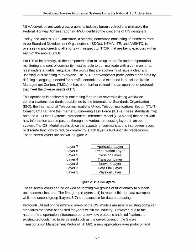
Developing Traveler Information Systems Using the National ITS Architecture
A-4
NEMA development work grew, a general industry forum evolved and ultimately theFederal Highway Administration (FHWA) identified the concerns of ITS designers.
Today, the Joint NTCIP Committee, a steering committee consisting of members fromthree Standard Development Organizations (SDOs), NEMA, ITE, and AASHTO, isoverseeing and directing all efforts with respect to NTCIP that are being executed withineach of the above SDOs.
For ITS to be a reality, all the components that make up the traffic and transportationmonitoring and control community must be able to communicate with a common, or atleast understandable, language. The words that are spoken must have a clear andunambiguous meaning to everyone. The NTCIP development participants started out bydefining a language needed for a traffic controller, and extended it to include TrafficManagement Centers (TMCs). It has been further refined into an open set of protocolsthat meet the diverse needs of ITS.
This openness is achieved by embracing features of several existing worldwidecommunications standards established by the International Standards Organization(ISO), the International Telecommunications Union, Telecommunications Sector (ITU-T;formerly CCITT), and the Internet Engineering Task Force (IETF). These standards maponto the ISO Open Systems Interconnect Reference Model (OSI Model) that deals withhow information can be passed through the various processing layers in an opensystem. The OSI Model breaks down the aspects of communications into seven layersor discrete functions to reduce complexity. Each layer is built upon its predecessor. These seven layers are shown in Figure A1.
Layer 7 Application LayerLayer 6 Presentation LayerLayer 5 Session LayerLayer 4 Transport LayerLayer 3 Network LayerLayer 2 Data Link LayerLayer 1 Physical Layer
Figure A-1: OSI Layers
These seven layers can be viewed as forming two groups of functionality to supportopen communications. The first group (Layers 1-4) is responsible for data transportwhile the second group (Layers 5-7) is responsible for data processing.
Protocols utilized on the different layers of the OSI models are mostly existing computerstandards that have been used for years within the industry. However, due to thenature of transportation infrastructures, a few new protocols and modifications toexisting protocols had to be defined such as the development of the SimpleTransportation Management Protocol (STMP), a new application layer protocol, and

Developing Traveler Information Systems Using the National ITS Architecture
A-5
Point-to-MultiPoint Protocol (PMPP), which follows the existing Point-to-Point Protocol(PPP). PMPP has not yet been approved.
Developing Traveler Information Systems Using the National ITS Architecture
A-6
A.2.1.1.1 Class ProfilesWithin the NTCIP there are various profile classes defined:
g A - Connectionless
g B - Central direct to field
g C - Connection oriented
g D - Dial-up
g E - Center to Center
g F - Alternate Center-to-Center
These classes are described below. The Class B Profile is the only Class Profile thathas been standardized to date. While development of this standard has beencompleted and it has been balloted with the results indicating that the standard isacceptable , as of February 1998, it has not reached a maturity level needed for finalapproval and publication by the Joint NTCIP Committee and for U.S. DOT rulesrequiring use in Federally funded ITS projects beyond a trial basis. However, it is notexpected to undergo any significant changes from testing and field trials. Manufacturers are developing compatible products and agencies are encouraged applythe standard.
A.2.1.1.2 Class A ProfileClass A is a suite of protocols allowing the connectionless transmission of data packetsover a medium that does not require a permanent connection between two devices. For example, when sending two letters via regular mail, it cannot be ensured that bothletters will take the same route (one letter might get from location A to location B vialocation C, while the other letter is sent via location D). The Class A Profile is based onexisting protocols already in use by the Internet community and other network systems,therefore utilizing proven protocols. The only exception is the utilization of STMP as theapplication layer protocol and a modified form of the HDLC protocol that includes aninitial protocol identifier (IPI) as the data link layer protocol.
The Class A Profile suite of protocols will use the Transmission Control Protocol (TCP)as its Transport Layer protocol to guarantee delivery or signal when a message cannotbe delivered correctly. TCP uses sequence and acknowledge information and timers tomake sure the individual frames are received and that they are put in their proper order.If a frame is garbled or lost, re-transmissions are attempted. If a frame cannot bedelivered, the upper layer is notified. This class of service ensures data integrity andcorrectness; its primary use is for large data transfers.
This standard has not yet been approved but is in the process of being developed bydevice manufacturers in conjunction with users of these devices. This developmentprocess ensures that the devices utilizing this protocol will meet the requirements of theuser community.
Developing Traveler Information Systems Using the National ITS Architecture
A-7
The main difference between the Class A Profile and the Class B Profile is that Class Amessages can be routed through an intermediate device, e.g., from a central location toa field device.
A.2.1.1.3 Class B ProfileThe NTCIP Class B Profile defines a set of communication protocols to be used in fielddevices and their management systems that are part of an Intelligent TransportationSystem. The profile provides for exchange of information between a primary stationand each secondary station on a particular communications channel or subnet. Theprofile sets forth standards to allow devices to share a common interconnect, establisha common language for them to communicate and define the structure under which thedata in these devices is structured and managed. It does not address the need for theexchange of information between devices on different subnets.
Class B provides for bandwidth efficient exchange of information between the primarystation and each secondary station on the same physical link. Class B does not ensuredelivery. Frames received with errors are discarded. If re-transmissions are needed, itis the responsibility of the Application Layer to provide them. This class of service isprimarily intended for short command and reply messages where delivery time is astrong consideration.
The Class B Profile can be used to poll or transmit data to and from roadside devicessuch as traffic signal controllers, surveillance detectors, variable message signs, orpreemption devices. It can also be used for communicating with traveler informationkiosks or similar devices. A prerequisite is the direct connection of management centerand roadside device, because the Class B Profile does not allow for routing ofmessages
A.2.1.1.4 Class C ProfileClass C is a profile providing connection-oriented services similar to the datatransmission within the Internet. In fact, the Class C Profile includes the same protocolson the Network (using Internet Protocol or IP) and Transport (using TCP) Layers of theOSI model. This profile is not yet finalized but will probably not include the untestedSimple Transportation Management Protocol (STMP), as required for the Class B andClass A Profiles. Instead, it will utilize the Simple Network Management Protocol(SNMP), TELNET, and the File Transfer Protocol (FTP), which are well-tested andimplemented within the Internet and intranet networks.
Class C may seem to provide the ideal service; however, it imposes additionaloverhead. Before any information can be passed, a connection between the devicesmust be established. The connection procedure takes a certain amount of time. Whenthe information transfer is completed, the connection must be formally closed.
Developing Traveler Information Systems Using the National ITS Architecture
A-8
The main difference between the Class C Profile and the Class B Profile is that Class Cmessages can be routed through an intermediate device, e.g., from a central location toa field device. Another aspect is the capability to “chop” large data files into smallerdata packets (file transfer) and to sequence these packets so that they can beassembled correctly at the receiving end.
A variety of traffic signal applications can benefit from the Class A and/or Class CProfiles. Different types of field devices, such as traffic signal controller, videosurveillance cameras, and variable message signs, from various different manufacturerscould be connected to one common communications line and still be controlled andmonitored from the traffic management center. Currently, it is not possible to connectexisting field devices that utilize different communications protocols to the samecommunications channel as NTCIP.
A.2.1.1.5 Class D ProfileThe Class D Profile is intended for dial-up connections. The protocol will includesecurity features such as dial-back. Development work on the Class D profile has notoccurred yet.
A.2.1.1.6 Class E ProfileThe Class E Profile specifies the suite of protocols that allows for center-to-centercommunications. The specification of this Profile is at a very preliminary stage and itsanticipated development completion date is 1999. One of the first steps in developingthis standard is the definition of the Transportation Management Data Dictionary(TMDD) specifying the content of data that needs to be transmitted betweenmanagement centers.
Several different existing and emerging protocols, mostly specifying the applicationlayer protocol and ultimately influencing the underlying layers of the OSI model, areunder consideration for this profile but a consensus has not been reached.
The transportation industry can utilize this standard to ensure compatibility betweenmultiple transportation management centers or service providers. The Class E Profileshould not be used separately unless the data format of messages to be exchanged areknown to both the transmitting and receiving management centers.
A.2.1.1.7 Class F ProfileAnother NTCIP compatible and NTCIP-compliant method for center-to-centercommunications has been introduced. The introduction of a Class F Profile took placein December 1996 but the information regarding this proposed standard developmenteffort has not yet been specified in writing.
A.2.1.1.8 Message Sets
Developing Traveler Information Systems Using the National ITS Architecture
A-9
NTCIP utilizes message sets that define how a particular function or parameter isdefined and described, and what the allowed ranges are for each parameter (or objectsas they are called). All objects have a unique name which is based on a location undera global tree. NEMA has a node (or branch) within the global tree and assigns uniquenames to each known and defined object. Because of the history, NEMA first tried todefine signal controller objects, but detected very quickly that many objects (parametersand/or functions) are not unique to signal controller applications (e.g., time) and createdanother message set that contains common objects (referred to as Global ObjectDefinitions). As of February 1998, five of these message sets have been completedand voted as acceptable and are available from NEMA (see Section 5). Manufacturersare developing compatible products and agencies are encouraged apply thesestandards.
A.2.1.1.9 Future DevelopmentsNTCIP is envisioned to cover many different types of communications. The flexibility ofNTCIP achieved through following the OSI Reference Model allows the expansion tovarious, not yet considered communications protocols on the different layers of the OSImodel. Interoperability is provided by defined interface setups (APIs) that the layerprotocols are required to follow.
A.2.1.2 TCIPThe Transit Communications Interface Profiles (TCIP) is a standards development effortthat may consist of several suites of protocols and data message sets. The TCIPstandar’s primary goal is the definition of data interfaces to both transit-relatedapplications and the National ITS Architecture data flows. Transit-related applicationinterfaces are anticipated to include the FTA National Transit GIS standard (underdevelopment, see below) and consider the Advanced Public Transit Systems (APTS)Map and Spatial Database User Requirement specifications (also under development)as well as the NTCIP, DSRC, and other standardization efforts. TCIP will be developedby addressing data flows as identified within the National ITS Architecture to thegreatest extent possible. Interfaces needed for other transit-related applications thathave not been addressed will also be identified.
The TCIP development effort is expected to augment the information management areaof NTCIP with transit-related information and message formats that facilitate theexchange of transit information among operations centers, transit vehicles and theinfrastructure. The TCIP will provide additional NTCIP Class Profiles or subsets ofexisting and planned Class Profiles, and the necessary bridges for information transferfrom legacy transit systems to advanced information systems developed conforming tothe National ITS Architecture. The characteristics of transit information exchange maybe best served, for example, by one of the five NTCIP Class Profiles, by one of theProfiles of SAE J1708, or by TCIP. However, the main focus of TCIP will be thedevelopment of message formats to exchange transit information in a standardizedmanner.

Developing Traveler Information Systems Using the National ITS Architecture
A-10
The TCIP effort is lead by the Institute of Transportation Engineers (ITE) and supportedby a large group of technical advisors consisting of members of the transit communitysuch as FTA, APTS, and APTA. ITE is a recognized Standard DevelopmentOrganization (SDO) that was awarded a contract by the US DOT to develop the TCIPstandard. As of February 1998, the time frame currently scheduled for the TCIPdevelopment ends in 1998.
The following have been identified as preliminary targets for the TCIP work:
1.) data flows internally and externally:
a) internal data flows: interdepartmental within a transit property or withinthe different branches (remote offices), TransitManagement Center (TrMC) to transit vehicles, transitkiosks, and other items such as roadside transmitters
b) external data flows: TrMC to TMC or other centers such as serviceproviders and financial agents (e.g., credit cardcompanies and banks)
2.) static reference and dynamic data transfers:
a) static reference data flows: for example, route and bus stop inventory, schedule,fare, and spatial data transfers
b) dynamic data flows: for example, pre-trip itinerary planning, safety andsecurity information, and detour and service delaydata transfers TCIP will ensure interoperability andcompatibility to NTCIP and SAE J1708/J1587 bycreating gateway protocols, also termed applicationprogramming interfaces (APIs).
Further information can be obtained from the following source:
<http://www.tcip.org>
A.2.1.4 Dedicated Short Range Communications (DSRC)Dedicated Short Range Communications (DSRC) consists of short-rangecommunications devices that are capable of transferring high rates of data over an airinterface between mobile or stationary vehicles and normally stationary devices that areeither mounted to structures along the roadway or are hand-held. One way ofaccomplishing these communications is through use of radio frequency (RF) beacons. RF beacon technology generally consists of a transponder (tag), transceiver (reader),and transceiver antenna (beacon). DSRC is also known as vehicle-roadsidecommunications (VRC).
The National ITS Architecture program recognized the need for DSRC systems forthose specific applications that require a close physical interaction between the vehicleand the roadside infrastructure, such as in toll collection, commercial vehicle electronic
Developing Traveler Information Systems Using the National ITS Architecture
A-11
clearance and roadside safety inspection, etc. However, DSRC is consideredinappropriate for applications such as route guidance that can be more efficientlyserved by wide-area ITS communications. Because of the dedicated nature and limitedrange of DSRC systems, the National ITS Architecture realizes that the costs ofdeploying DSRC will have to be absorbed by the ITS applications they support,including both public and private investment. The technical and applications aspects ofDSRC are covered in the Communications, Physical Architecture and Theory ofOperations documents produced by the National ITS Architecture program.
The following applications have been identified as candidates to utilize DSRC as aprimary communications technique or mechanism:
g Electronic Toll and Parking Payments
g Commercial Vehicle Operations
$ International Border Clearance
$ Electronic Clearance
$ Safety Inspection
$ Automated Equipment Identification and Freight Management
$ Off-Line Verification
g Transit and Emergency Vehicle Operations
g Fleet Management
g Use of Vehicles as Probes to Obtain Link Travel Times
g In-Vehicle Signing
g Intersection Collision Avoidance and Automated Highway Systems
g Commercial Applications (e.g., drive-through purchases)
g Intersection Safety Warning
To encourage development of nationally, and perhaps internationally, compatibleIntelligent Transportation Systems using DSRC, the ITS Joint Program Office (JPO) inthe U.S. Department of Transportation has promoted the voluntary consensusdevelopment approach with wide private and public participation. Leading this effortare the American Society for Testing and Materials (ASTM) and Institute of Electricaland Electronic Engineers (IEEE).
A.3 Automated Vehicle Location (AVL) SystemsThe application of AVL is a very beneficial application in terms of implementing ITStechnologies. It will enable fleet, transit and emergency services managers to managevehicles in real-time with reference to the roadway network.
There are many AVL systems in existence. However, all of these AVL systems areproprietary, locking implementing agencies into a vendor-specific system. Most of theseAVL systems have not been designed to allow for integration with an overall

Developing Traveler Information Systems Using the National ITS Architecture
A-12
management system. Therefore, expansion to include upgrades, include othersubsystems, or the integration of an AVL system into an overall management systemwill be very expensive.
The transportation industry has expressed the need for an AVL standard to allow forinteroperability and integration of subsystems. The U.S. DOT placed AVL high on thepriority list of standards that need to be developed for ITS technologies.
The Institute of Electrical and Electronic Engineers (IEEE) has been designated as thelead organization to develop the message set (applications standard) for AVL. However, other standards specifying the communications protocols are also needed.
Currently existing and planned standards usable for AVL are listed in the ITS StandardsCatalog available on-line at the following World Wide Web site:
<http://www.itsa.org>
A.4 Traveler Information Systems Standards Standards-setting organizations have identified traveler information message lists asfundamental for achieving broad interoperability of ITS throughout the world. Suchmessage lists and data dictionaries are necessary for the development of protocols thatwill permit modular system implementation, allow regional or national systems tointerconnect, and will promote competition in the ITS marketplace. To this end, effortshave begun by the Joint SAE/ITS America ATIS Standards Committee to develop amessage list and data dictionary standard for ATIS messages, taking into accountdifferent end user services, media, and devices. A primary basis of this effort will be theNational ITS Architecture, along with existing message sets from field experience.
A.4.1 ATIS Data DictionaryThe ATIS data dictionary is a minimum set of medium-independent messages and data elementsneeded by potential information service providers (ISP’s) to deploy ATIS services, and providethe basis for future interoperability of ATIS devices. The general objective is to create initialstandards for data elements and messages that are essential to the provision of information totravelers in the next few years as this new market develops. The focus is intended to bepragmatic by dealing at first only with those data and messages where there is a clear, currentmarket and industry demand. At the same time, this is intended to be comprehensive andsystematic in looking at all stages of travel (pre-trip and en route), all types of travelers (drivers,passengers), all categories of information (advisory, route guidance, traveler services, etc.) allmeans of surface travel (auto, truck, transit, etc.), and all platforms for delivery of travelerinformation (in-vehicle, portable devices, kiosks in mobile, public, work, and home environments).
Developing Traveler Information Systems Using the National ITS Architecture
A-13
A.4.2 ATIS Message Data Flow This effort is being addressed in SAE draft document J2369. ATIS messagesoriginating from a TMC or ISP are sent via wireline or microwave link to the broadcasterwho may combine the data stream with other broadcast digital data such as pagingmessages. The data is J2369 encoded and sent to the transmitter. Data received by amobile user is J2369 decoded and translated to a usable format based on the givenapplication. In the case of an in-vehicle application, data is translated and sent to theIDB for distribution to other vehicle systems.
A.5 Other ATIS-Related Standards
A.5.1 ITS Data Bus (IDB)Chartered in late 1995, the SAE Data Bus Committee is targeting its work toward theconcept of a dedicated ITS data bus that may be installed on a vehicle to work inparallel with existing automotive electronics. The data bus will facilitate the addition ofITS electronics devices to vehicles without endangering any of its systems.
A.5.1.1 IDB Protocol StandardThe objective of this standard is to provide an open architecture to permitinteroperability that will allow manufacturers, dealers, and vehicle buyers to install awide range of electronics equipment in vehicles at any time during the vehicle’s lifecycle, with little or no expert assistance required.
This effort is aimed at developing SAE recommended practices and standards thatdefine an ITS data bus, message formats, message header codes, node ID’s,application services and service codes, data definitions, diagnostic connectors,diagnostic services and test mode codes, ITS Data Bus-Vehicle Bus gateway servicesand service codes, network management services/functionality, and other areas as maybe needed. The standard will be developed in cooperation with EIA/CEMA, CTIA, theSAE Multiplex and Diagnostics Committees, and other interested standards developingorganizations.
The ITS Data Bus Protocol Standard J2366 will include specifications such as powerratings and moding, environmental, physical, mechanical, and electrical performancerequirements and will also cover the specifications of the appropriate protocol layers forthe ITS Data Bus application. Internet access from the car is still being considered as arequirement.
Developing Traveler Information Systems Using the National ITS Architecture
A-14
A.5.1.2 ITS Data Bus Vehicle Gateway Reference Design Recommended PracticeThe scope of standard J2367 will cover the performance specifications of the vehiclegateway-specific aspects of J2366, including the minimum set of messages propagatedacross the gateway and performance issues such as gateway latency, etc., but willleave the packaging issues to the OEM.
A.5.1.3 ITS Data Bus Conformance Testing StandardThe scope of this standard will be to specify the set of testing procedures required tocertify a device as being IDB compliant.
A.5.2 In-Vehicle Systems Interface Standards
A.5.2.1 High Speed FM SubCarrier This effort of the SAE In-Vehicle Systems Interface Committee (IVSIC) is in cooperationof the NAB-EIA-NRSC, who is testing several systems to become U.S. transmissionstandards. J2369 will specify a general framework and set of message formats thatallow cooperative transmission of Advanced Traveler Information System (ATIS) Dataover FM SubCarrier. The expertise to perform the message coding resides in the SAEdivision and among other ITS practitioners, while the oversight of suitable systembandwidth and other parameters resides with the National Association of Broadcasters(NAB). The resulting SAE standard would be incorporated in the master specificationdeveloped by NRSC. At present, the SAE IVSI Committee has established “real-timetraffic,” “historical,” and “pre-planned incidents” as priorities for ATIS messagedevelopment. The initial focus of the project is to create a preliminary coding andmessage structure for link travel times and network support functions for deployment ofthe standard modulation selected by the NRSC High Speed Committee. The project willdraw on various message sets being developed elsewhere, formatting them specificallyfor transmission in FM SubCarrier modulation. The SAE IVSIC will then expand thescope of the project to include additional messages beyond link travel times, such astransit schedules. The Committee continues to address incident numbering, indexingmethods, naming methodology, and interoperability issues. Draft of J2369 is scheduledfor completion by the end of 1997.
Developing Traveler Information Systems Using the National ITS Architecture
A-15
A.5.2.2 On-Board Land Vehicle MaydaySAE Standard J2313 addresses the On-Board Land Vehicle Mayday ReportingInterface. At this time, over 30 different private firms are fielding early Mayday systemsthat do not have any inter-compatibility and do not directly talk to, or receivecooperation with, the existing National, State, and Local level “911” response agencies.Today, most of these systems are simple cellular phones equipped with a GPS and amodem. However, future systems are expected to be heavily integrated into the vehicleelectronics suite and will be capable of fully automated deployment without humanintervention. The interests of public service versus private profit, combined with a publicperception that such systems should have a basic level of functionality anywhere in thecountry, can only be met by developing in a way that components can work togetherwith common interface standards. This specification J(2313) is being developed bySAE to further industry standards in two key areas. First, the message content thatvehicles can be expected to exchange with the response agency. Second, internalmethods of interconnection between this sub-system and other safety electronics in thevehicle. Finally, it prescribes various protocol methods so that vendors with differentcommunication methods can speak to the response agency in a standard format, thussaving public investment capital and fostering a basic level expected performance.
A.5.3 Navigation StandardsPosition and location determination, route planning, route following, route guidance,traffic data functions, probe functions, communications strategies, and upper layerprotocol are among the focus issues for the SAE Navigation Committee. They willevaluate these aspects and determine which standards may be beneficial incontributing to the overall safety of those types of systems. The group will provide directbenefit to users by assuring interoperability among subsystems that may be provided bymore than one manufacturer, and helping to define the minimum functionality thatwould be considered “ITS- compatible.”
The information contained in this Appendix, Parts A.4 and A.5 was drawn withpermission from the SAE web site. Further information on all the SAE ITS standardscan be obtained at:
<http://www.sae.org/TECHCMTE/gits.htm>.
Developing Traveler Information Systems Using the National ITS Architecture TechnicalEdition
B-1
Appendix B. Glossary
Advanced Traffic Management Systems (ATMS) - The Advanced Traffic ManagementSystem category of ITS functions. Includes adaptive traffic signal control, electronicroad pricing, and toll collection.
Advanced Traveler Information Systems (ATIS) - The Advanced Traveler InformationSystem category of ITS functions. Includes vehicle navigation, route guidance, in-vehicle signage, intermodal travel information, trip planning, and maydaycommunication.
Algorithm - A procedure, process, or rule for the solution of a problem in a finite numberof steps. An algorithm may be a set of computational rules for the solution of amathematical problem or for evaluating a function.
Advanced Public Transportation Systems (APTS) - The Advanced Public TransportationSystem category of the ITS functions. Includes vehicle location and schedulemonitoring, real-time transit, ride-share and HOV information.
Architecture Flow - A grouping of data flows (from the logical architecture) thatoriginate at one subsystem and end at another (in the physical architecture).
Automated Vehicle Identification (AVI) - System that has three functional elements: avehicle-mounted transponder (also known as a vehicle tag); roadside reader unit (alsoknown as a tag reader); and a processing control unit.
Automated Vehicle Location (AVL) - A computerized system that tracks the currentlocation of vehicles, buses, etc., enabling fleets to function more efficiently.
Bus Priority - Cycle-by-cycle timing of a traffic signal so the beginning and end times ofgreen may be shifted to minimize delay to approaching buses. The normal sequence ofsignal displays is usually maintained.
CCTV - Closed Circuit Television
CCTV Monitoring Systems - Advanced traffic management systems with continuousCCTV coverage of the transportation facilities (e.g. freeways, intersections, bridges).
Communication System - The composite of communication links and associatedcommunications equipment which interconnect all the control and surveillancecomponents of a traffic control system.
Communications Addressing - The process of selecting a specific receiving unit on amultidrop line or network so that the message can be sent to the unit alone.

Developing Traveler Information Systems Using the National ITS Architecture TechnicalEdition
B-2
Congestion - A freeway condition where traffic demand exceeds roadway capacity. Normally occurs during peak travel periods or when a traffic incident reduces capacityby creating a bottleneck.
Council of ITS Standards - The council established by ITS America (Standards andProtocol Committee) to coordinate the standards-setting efforts in USA andinternational. Includes representatives from ANSI, IEEE, SAE, ASTM, EIA, NAB,NEMA, TIA, ITE, and AASHTO.
Delay - The retardation of traffic flow through a segment of roadway or intersection for adefinite period of time.
Demand - The need for service, e.g., the number of vehicles desiring use of a givensegment of roadway or intersection during a specified unit of time.
Detector - A device for indicating the presence or passage of vehicle or pedestrians. The general term is usually supplemented with a modifier; loop detector, magneticdetectors, etc. indicating type.
Diversion - An aspect of corridor control which refers to the directing of traffic from acorridor with excess demand to those with excess capacity.
Diversion Strategy - a strategy for diverting traffic that optimizes corridor operations inresponse to corridor incidents.
Emergency Management - The bundle of ITS user services that includes; emergencynotification and personal security; and emergency vehicle management.
Emergency Vehicle Preemption - The transfer of the normal control of signals to aspecial signal control mode for emergency vehicles.
Equipment Packages - A grouping by function or p-specs of a given subsystem intoimplementable packages of hardware and software.
Equipment Status Monitoring - The ability to determine the operational characteristicsof a remote device in terms of: operating normally, malfunctions, communications errors ,etc.
Global Positioning System (GPS) - A spaced-based radionavigation system comprisedof a constellation of satellites that transmit navigation signals, allowing a vehicle todetermine the real-time position of its navigation receiver.
Hardware - The physical equipment in a computer system. (see Software).
Highway Advisory Radio (HAR) - Also know as Traveler’s Information Stations (TIS), orTraveler’s Advisory Radio (TAR). These systems provide travel or roadway informationto motorists via their AM radio sets. The FCC regulates the use of HAR.
Developing Traveler Information Systems Using the National ITS Architecture TechnicalEdition
B-3
Information Service Provider - A subsystem of the National ITS Architecture whichprovides the capabilities to collect, process, store, and disseminate traveler informationto subscribers and the public at large. Information provided includes basic advisories,real time traffic condition and transit schedule information, yellow pages information,ridematching information, and parking information. The subsystem also provides thecapability to provide specific directions to travelers by receiving origin and destinationrequests from travelers, generating route plans, and returning the calculated plans tothe users
Incident - An occurrence in the traffic stream which causes a reduction in capacity orabnormal increase in demand. Common incidents include accidents, stalled vehicles,spilled loads, and special events.
Intelligent Transportation Systems (ITS) - The collection of transportation services andinfrastructure that will implement the goals of ISTEA. ITS uses advanced technologiesto provide the range of traffic-based user services.
Intermodal - Those issues or activities which involve of affect more than one mode oftransportation, including transportation connections, choices, cooperation andcoordination of various modes. Also known as “multimodal.”
Intermodal Surface Transportation Efficiency Act of 1991 (ISTEA-91) - A Congressionalact whose purpose is to develop a National Intermodal Transportation System that iseconomical efficient and environmentally sound, provide the foundation to compete inthe global economy and move people and goods in an energy efficient manner. Provides governmental basis for research and deployment of ITS technologies.
International Organization for Standardization (ISO) - An international standardsorganization. ANSI is the U.S. representative to ISO.
Internet - A vast collection of interconnected networks that all use TCP/IP which evolvedfrom ARPANET in the late 1960s and early 1970s. The Internet is a global network andis not proprietary. It has become a major medium to make information available(including traveler information).
Kiosk - In the transportation context, an interactive computer center for traffic or travelrelated information. Usually located in shopping malls, hotels, airports, businesses, andtransit terminals, kiosks provide pre-recorded and real-time information using text,sound, graphics, and video clips.
Layer - A breakdown or stratification of the physical architecture; comprised of thetransportation layer and the communications layer.
Logical Architecture - The identification of system functional processes and informationflows grouped to form particular transportation management functions. These
Developing Traveler Information Systems Using the National ITS Architecture TechnicalEdition
B-4
processes are broken down into subprocesses and further into process specifications orp-specs.
Market Packages - Within the National ITS Architecture, a set of equipment packagesrequired to work together to deliver a given service and the major architecture flowsbetween them and other important external systems.
Measures of Effectiveness (MOE) - The quantitative variables derived from trafficmeasurements that measure the improvement in traffic operations ranging from onesignalized intersection to a complete system. Common MOEs are total travel time, totaltravel, number and recent of stops, delay, average speed, accident rate, andthroughput.
National Transportation Communications for ITS Protocol (NTCIP) - A family ofprotocols being developed for the transportation community.
NEMA - National Electrical Manufacturers Association, a standards development body.
Open Systems Interconnect Reference Model (OSI Model) - A communications modelestablished by the International Standards Organization (ISO) that breaks down theaspects of communications into seven layers or discrete functions to reduce complexityand provide support for open communications. The layers range from the physical layerto the application layer.
Personal Digital Assistant (PDA) - A compact processor, typically smaller than apersonal laptop computer. Its size makes it convenient to carry when traveling. ManyPDAs can be connected to a portable wireless modem or can be accessorized withpager modules. This allows the PDA to receive transportation information broadcastover wireless communications channels.
Physical Architecture - The physical (versus functional) view or representation of asystem.
Process Specifications - The lowest level of functional hierarchy, process specifications(also know as p-specs) are elemental functions that must be performed to satisfy userservice requirements.
Preemption/Priority Systems - Preemption control of normal signal timing plans appliesin the following situations: priority for selected transit vehicles; preemption foremergency vehicles; and preemption for approaching trains at signals adjacent torailroad grade crossings.
Project Management - A management process that transforms a design into an installedsystem. Uses management tools such as: contract administration; project scheduling;construction management; work breakdown structure; defined and budgeted workpackages; project design reviews and audits; and costs/progress status reports. This
Developing Traveler Information Systems Using the National ITS Architecture TechnicalEdition
B-5
process carries forward the implementation of the system design. Tasks include:procurement of subsystems, software, and equipment, contractor performancemonitoring, documentation; design reviews, development, integration, developmenttesting, acceptance testing; training, hands-on training, and turnover to user, followedby a warranty period covering design, construction, installation and operational
Queue Detector - (1) A vehicle presence detector installed on a freeway entrance rampjust downstream of the frontage road to detect queue spillback onto the frontage road.(2) Component of a traffic signal control system which senses the presence (or number)of vehicles waiting in a queue.
Queue Length - (1) Number of vehicles stopped in a lane behind the stopline at a trafficsignal. (2) Number of vehicles that are stopped or moving in a line where the movementof each vehicle is constrained by that of the lead vehicle.
Ramp Metering - The most widely used form of freeway traffic control. It regulates thenumber of vehicles entering the freeway over a given time interval so that demand doesnot exceed capacity.
Recurrent Congestion - A type of congestion which is routinely expected at predictablelocations during specific time periods
Roadside Radio - Type of driver information system by which messages are conveyed tomotorists from local transmitters beside the roadway to radio receivers in their vehicles.
Route Preemption - Emergency vehicles have pre-planned routes that are incorporatedinto the signal system. Signal control on an emergency basis can be modified at EMS,fire, or police headquarters.
Signal Priority Systems - Priority control at signalized intersections are typically used forreduction of transit delay. Conditional signal priority for transit vehicles can beimplemented through: phase/green extension; phase early start or red truncation; redinterrupt or special phase; phase suppression or skipping; and window stretching.
Smart Card - Card with a computer chip embedded in plastic. The user transfers a cashvalue to the card’s microchip. The card can then be used to pay subway, bus, tolls, orparking fees.
Software - Various computer programs to facilitate the efficient operation of the system. Software items include: assemblers; compilers, generators; subroutines; libraries;operating systems; and application programs.
Software Maintenance - Those tasks required to locate and correct errors remaining incomputer programs after they are placed in operation, as well as making other programmodifications to meet the demands of changing system needs. This is an ongoingactivity that is required on any large automated system.
Developing Traveler Information Systems Using the National ITS Architecture TechnicalEdition
B-6
Subsystem - A physical entity within the transportation layer of the National ITSArchitecture.
Threshold - A present level or value of a parameter which indicates that a change ofactivity will occur if the current value is above or below this level.
Transit Communications Interface Profiles (TCIP) - A subset of NTCIP protocols whichare specific to the transit community.
User Service - Those ITS functional capabilities provided to address identified problemsor needs of a distinct user community.
User Service Bundle - A collection of ITS user services that have commoncharacteristics and can be deployed in a coordinated manner.
User Service Requirements - The decomposition of each user service into fundamentalneeds.
Variable Message Sign - Also referred to as Changeable Message Signs (CMS) orDynamic Message Signs (DMS). Signs that electronically or mechanically vary thevisual word, number or symbolic display as traffic conditions warrant. Also referred to aschangeable message signs or as dynamic message signs.
Wide Area Network - Any one of a number of technologies that provides geographicallydistant transfer.
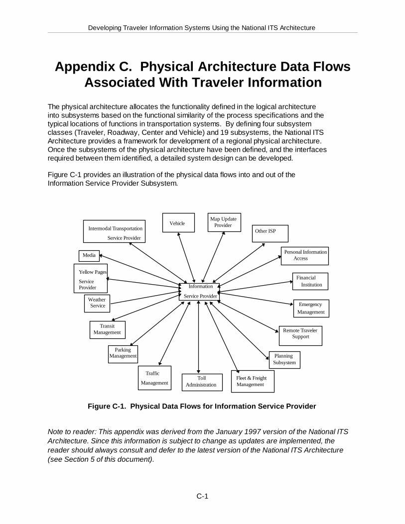
Developing Traveler Information Systems Using the National ITS Architecture
C-1
Appendix C. Physical Architecture Data FlowsAssociated With Traveler Information
The physical architecture allocates the functionality defined in the logical architectureinto subsystems based on the functional similarity of the process specifications and thetypical locations of functions in transportation systems. By defining four subsystemclasses (Traveler, Roadway, Center and Vehicle) and 19 subsystems, the National ITSArchitecture provides a framework for development of a regional physical architecture.Once the subsystems of the physical architecture have been defined, and the interfacesrequired between them identified, a detailed system design can be developed.
Figure C-1 provides an illustration of the physical data flows into and out of theInformation Service Provider Subsystem.
Information
Service Provider
Intermodal Transportation
Service Provider
VehicleMap Update
ProviderOther ISP
Personal InformationAccess
FinancialInstitution
EmergencyManagement
PlanningSubsystem
Fleet & FreightManagement
TollAdministration
Traffic
Management
TransitManagement
Weather Service
Yellow Pages
ServiceProvider
Media
Remote TravelerSupport
ParkingManagement
Figure C-1. Physical Data Flows for Information Service Provider
Note to reader: This appendix was derived from the January 1997 version of the National ITSArchitecture. Since this information is subject to change as updates are implemented, thereader should always consult and defer to the latest version of the National ITS Architecture(see Section 5 of this document).
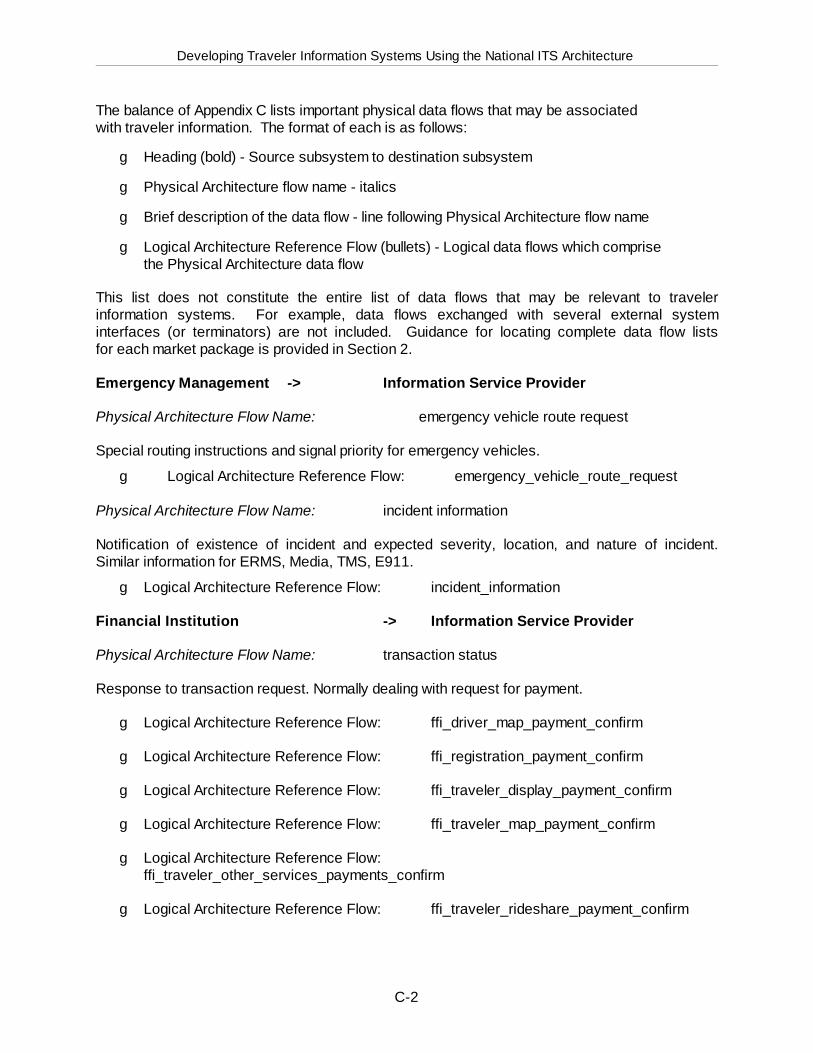
Developing Traveler Information Systems Using the National ITS Architecture
C-2
The balance of Appendix C lists important physical data flows that may be associatedwith traveler information. The format of each is as follows:
g Heading (bold) - Source subsystem to destination subsystem
g Physical Architecture flow name - italics
g Brief description of the data flow - line following Physical Architecture flow name
g Logical Architecture Reference Flow (bullets) - Logical data flows which comprisethe Physical Architecture data flow
This list does not constitute the entire list of data flows that may be relevant to travelerinformation systems. For example, data flows exchanged with several external systeminterfaces (or terminators) are not included. Guidance for locating complete data flow listsfor each market package is provided in Section 2.
Emergency Management -> Information Service Provider
Physical Architecture Flow Name: emergency vehicle route request
Special routing instructions and signal priority for emergency vehicles.
g Logical Architecture Reference Flow: emergency_vehicle_route_request
Physical Architecture Flow Name: incident information
Notification of existence of incident and expected severity, location, and nature of incident.Similar information for ERMS, Media, TMS, E911.
g Logical Architecture Reference Flow: incident_information
Financial Institution -> Information Service Provider
Physical Architecture Flow Name: transaction status
Response to transaction request. Normally dealing with request for payment.
g Logical Architecture Reference Flow: ffi_driver_map_payment_confirm
g Logical Architecture Reference Flow: ffi_registration_payment_confirm
g Logical Architecture Reference Flow: ffi_traveler_display_payment_confirm
g Logical Architecture Reference Flow: ffi_traveler_map_payment_confirm
g Logical Architecture Reference Flow: ffi_traveler_other_services_payments_confirm
g Logical Architecture Reference Flow: ffi_traveler_rideshare_payment_confirm
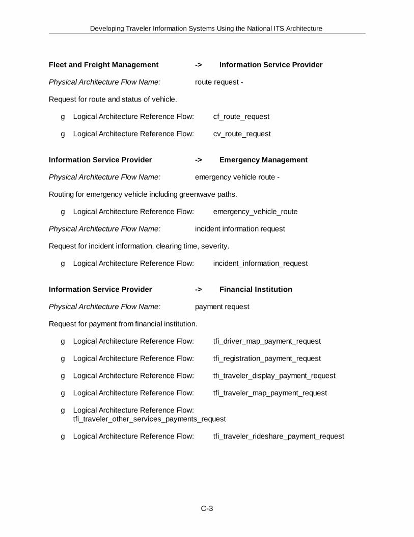
Developing Traveler Information Systems Using the National ITS Architecture
C-3
Fleet and Freight Management -> Information Service Provider
Physical Architecture Flow Name: route request -
Request for route and status of vehicle.
g Logical Architecture Reference Flow: cf_route_request
g Logical Architecture Reference Flow: cv_route_request
Information Service Provider -> Emergency Management
Physical Architecture Flow Name: emergency vehicle route -
Routing for emergency vehicle including greenwave paths.
g Logical Architecture Reference Flow: emergency_vehicle_route
Physical Architecture Flow Name: incident information request
Request for incident information, clearing time, severity.
g Logical Architecture Reference Flow: incident_information_request
Information Service Provider -> Financial Institution
Physical Architecture Flow Name: payment request
Request for payment from financial institution.
g Logical Architecture Reference Flow: tfi_driver_map_payment_request
g Logical Architecture Reference Flow: tfi_registration_payment_request
g Logical Architecture Reference Flow: tfi_traveler_display_payment_request
g Logical Architecture Reference Flow: tfi_traveler_map_payment_request
g Logical Architecture Reference Flow: tfi_traveler_other_services_payments_request
g Logical Architecture Reference Flow: tfi_traveler_rideshare_payment_request
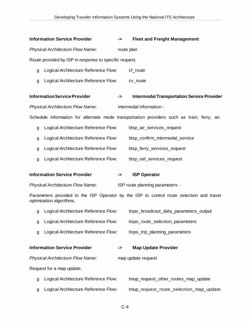
Developing Traveler Information Systems Using the National ITS Architecture
C-4
Information Service Provider -> Fleet and Freight Management
Physical Architecture Flow Name: route plan
Route provided by ISP in response to specific request.
g Logical Architecture Reference Flow: cf_route
g Logical Architecture Reference Flow: cv_route
Information Service Provider -> Intermodal Transportation Service Provider
Physical Architecture Flow Name: intermodal information -
Schedule information for alternate mode transportation providers such as train, ferry, air.
g Logical Architecture Reference Flow: titsp_air_services_request
g Logical Architecture Reference Flow: titsp_confirm_intermodal_service
g Logical Architecture Reference Flow: titsp_ferry_services_request
g Logical Architecture Reference Flow: titsp_rail_services_request
Information Service Provider -> ISP Operator
Physical Architecture Flow Name: ISP route planning parameters -
Parameters provided to the ISP Operator by the ISP to control route selection and traveloptimization algorithms.
g Logical Architecture Reference Flow: tispo_broadcast_data_parameters_output
g Logical Architecture Reference Flow: tispo_route_selection_parameters
g Logical Architecture Reference Flow: tispo_trip_planning_parameters
Information Service Provider -> Map Update Provider
Physical Architecture Flow Name: map update request
Request for a map update.
g Logical Architecture Reference Flow: tmup_request_other_routes_map_update
g Logical Architecture Reference Flow: tmup_request_route_selection_map_update
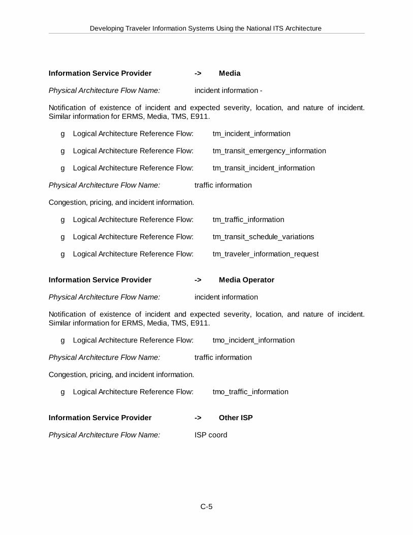
Developing Traveler Information Systems Using the National ITS Architecture
C-5
Information Service Provider -> Media
Physical Architecture Flow Name: incident information -
Notification of existence of incident and expected severity, location, and nature of incident.Similar information for ERMS, Media, TMS, E911.
g Logical Architecture Reference Flow: tm_incident_information
g Logical Architecture Reference Flow: tm_transit_emergency_information
g Logical Architecture Reference Flow: tm_transit_incident_information
Physical Architecture Flow Name: traffic information
Congestion, pricing, and incident information.
g Logical Architecture Reference Flow: tm_traffic_information
g Logical Architecture Reference Flow: tm_transit_schedule_variations
g Logical Architecture Reference Flow: tm_traveler_information_request
Information Service Provider -> Media Operator
Physical Architecture Flow Name: incident information
Notification of existence of incident and expected severity, location, and nature of incident.Similar information for ERMS, Media, TMS, E911.
g Logical Architecture Reference Flow: tmo_incident_information
Physical Architecture Flow Name: traffic information
Congestion, pricing, and incident information.
g Logical Architecture Reference Flow: tmo_traffic_information
Information Service Provider -> Other ISP
Physical Architecture Flow Name: ISP coord
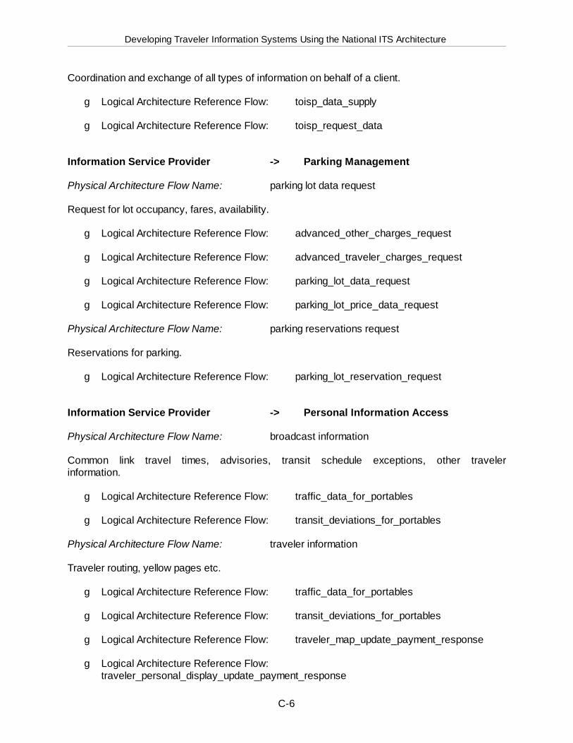
Developing Traveler Information Systems Using the National ITS Architecture
C-6
Coordination and exchange of all types of information on behalf of a client.
g Logical Architecture Reference Flow: toisp_data_supply
g Logical Architecture Reference Flow: toisp_request_data
Information Service Provider -> Parking Management
Physical Architecture Flow Name: parking lot data request
Request for lot occupancy, fares, availability.
g Logical Architecture Reference Flow: advanced_other_charges_request
g Logical Architecture Reference Flow: advanced_traveler_charges_request
g Logical Architecture Reference Flow: parking_lot_data_request
g Logical Architecture Reference Flow: parking_lot_price_data_request
Physical Architecture Flow Name: parking reservations request
Reservations for parking.
g Logical Architecture Reference Flow: parking_lot_reservation_request
Information Service Provider -> Personal Information Access
Physical Architecture Flow Name: broadcast information
Common link travel times, advisories, transit schedule exceptions, other travelerinformation.
g Logical Architecture Reference Flow: traffic_data_for_portables
g Logical Architecture Reference Flow: transit_deviations_for_portables
Physical Architecture Flow Name: traveler information
Traveler routing, yellow pages etc.
g Logical Architecture Reference Flow: traffic_data_for_portables
g Logical Architecture Reference Flow: transit_deviations_for_portables
g Logical Architecture Reference Flow: traveler_map_update_payment_response
g Logical Architecture Reference Flow: traveler_personal_display_update_payment_response
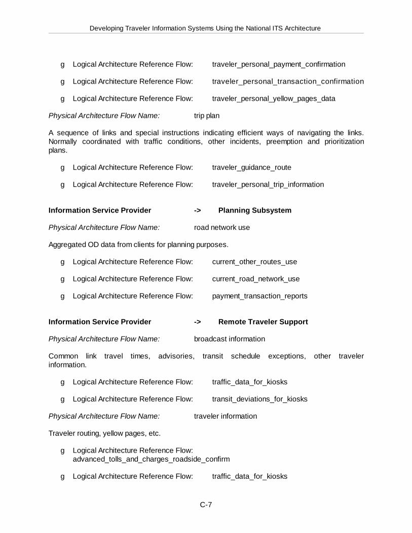
Developing Traveler Information Systems Using the National ITS Architecture
C-7
g Logical Architecture Reference Flow: traveler_personal_payment_confirmation
g Logical Architecture Reference Flow: traveler_personal_transaction_confirmation
g Logical Architecture Reference Flow: traveler_personal_yellow_pages_data
Physical Architecture Flow Name: trip plan
A sequence of links and special instructions indicating efficient ways of navigating the links.Normally coordinated with traffic conditions, other incidents, preemption and prioritizationplans.
g Logical Architecture Reference Flow: traveler_guidance_route
g Logical Architecture Reference Flow: traveler_personal_trip_information
Information Service Provider -> Planning Subsystem
Physical Architecture Flow Name: road network use
Aggregated OD data from clients for planning purposes.
g Logical Architecture Reference Flow: current_other_routes_use
g Logical Architecture Reference Flow: current_road_network_use
g Logical Architecture Reference Flow: payment_transaction_reports
Information Service Provider -> Remote Traveler Support
Physical Architecture Flow Name: broadcast information
Common link travel times, advisories, transit schedule exceptions, other travelerinformation.
g Logical Architecture Reference Flow: traffic_data_for_kiosks
g Logical Architecture Reference Flow: transit_deviations_for_kiosks
Physical Architecture Flow Name: traveler information
Traveler routing, yellow pages, etc.
g Logical Architecture Reference Flow: advanced_tolls_and_charges_roadside_confirm
g Logical Architecture Reference Flow: traffic_data_for_kiosks
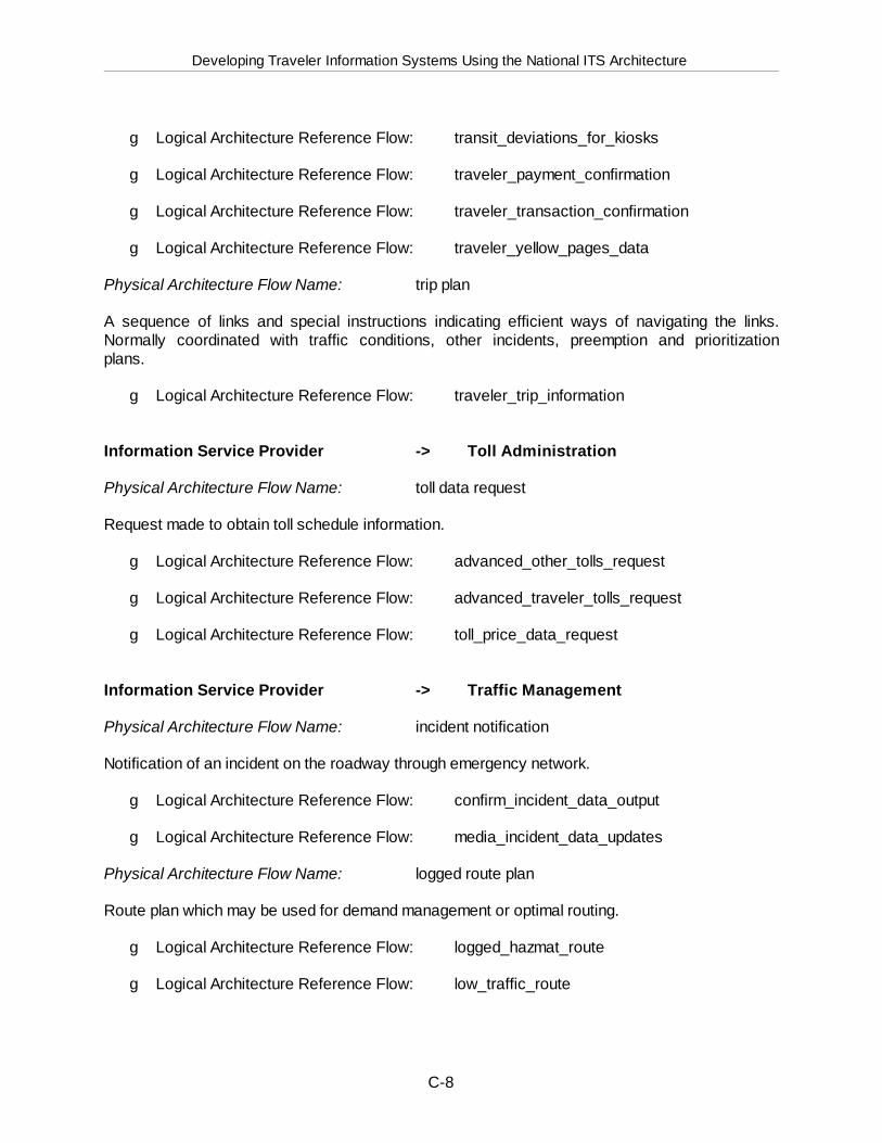
Developing Traveler Information Systems Using the National ITS Architecture
C-8
g Logical Architecture Reference Flow: transit_deviations_for_kiosks
g Logical Architecture Reference Flow: traveler_payment_confirmation
g Logical Architecture Reference Flow: traveler_transaction_confirmation
g Logical Architecture Reference Flow: traveler_yellow_pages_data
Physical Architecture Flow Name: trip plan
A sequence of links and special instructions indicating efficient ways of navigating the links.Normally coordinated with traffic conditions, other incidents, preemption and prioritizationplans.
g Logical Architecture Reference Flow: traveler_trip_information
Information Service Provider -> Toll Administration
Physical Architecture Flow Name: toll data request
Request made to obtain toll schedule information.
g Logical Architecture Reference Flow: advanced_other_tolls_request
g Logical Architecture Reference Flow: advanced_traveler_tolls_request
g Logical Architecture Reference Flow: toll_price_data_request
Information Service Provider -> Traffic Management
Physical Architecture Flow Name: incident notification
Notification of an incident on the roadway through emergency network.
g Logical Architecture Reference Flow: confirm_incident_data_output
g Logical Architecture Reference Flow: media_incident_data_updates
Physical Architecture Flow Name: logged route plan
Route plan which may be used for demand management or optimal routing.
g Logical Architecture Reference Flow: logged_hazmat_route
g Logical Architecture Reference Flow: low_traffic_route
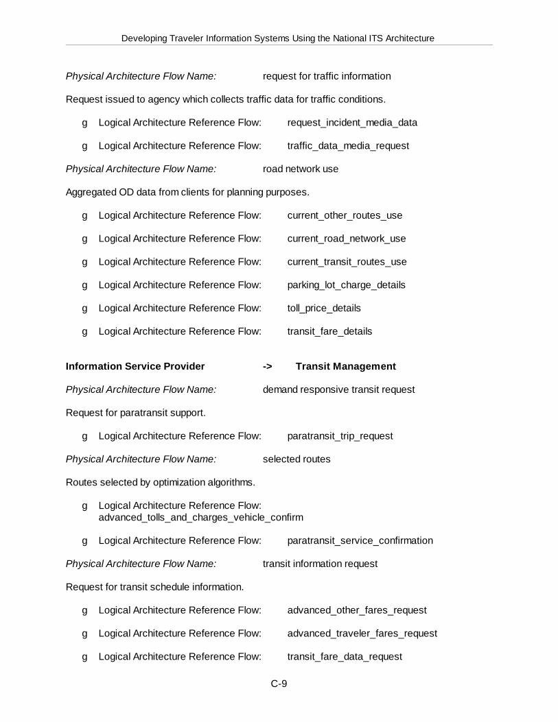
Developing Traveler Information Systems Using the National ITS Architecture
C-9
Physical Architecture Flow Name: request for traffic information
Request issued to agency which collects traffic data for traffic conditions.
g Logical Architecture Reference Flow: request_incident_media_data
g Logical Architecture Reference Flow: traffic_data_media_request
Physical Architecture Flow Name: road network use
Aggregated OD data from clients for planning purposes.
g Logical Architecture Reference Flow: current_other_routes_use
g Logical Architecture Reference Flow: current_road_network_use
g Logical Architecture Reference Flow: current_transit_routes_use
g Logical Architecture Reference Flow: parking_lot_charge_details
g Logical Architecture Reference Flow: toll_price_details
g Logical Architecture Reference Flow: transit_fare_details
Information Service Provider -> Transit Management
Physical Architecture Flow Name: demand responsive transit request
Request for paratransit support.
g Logical Architecture Reference Flow: paratransit_trip_request
Physical Architecture Flow Name: selected routes
Routes selected by optimization algorithms.
g Logical Architecture Reference Flow: advanced_tolls_and_charges_vehicle_confirm
g Logical Architecture Reference Flow: paratransit_service_confirmation
Physical Architecture Flow Name: transit information request
Request for transit schedule information.
g Logical Architecture Reference Flow: advanced_other_fares_request
g Logical Architecture Reference Flow: advanced_traveler_fares_request
g Logical Architecture Reference Flow: transit_fare_data_request
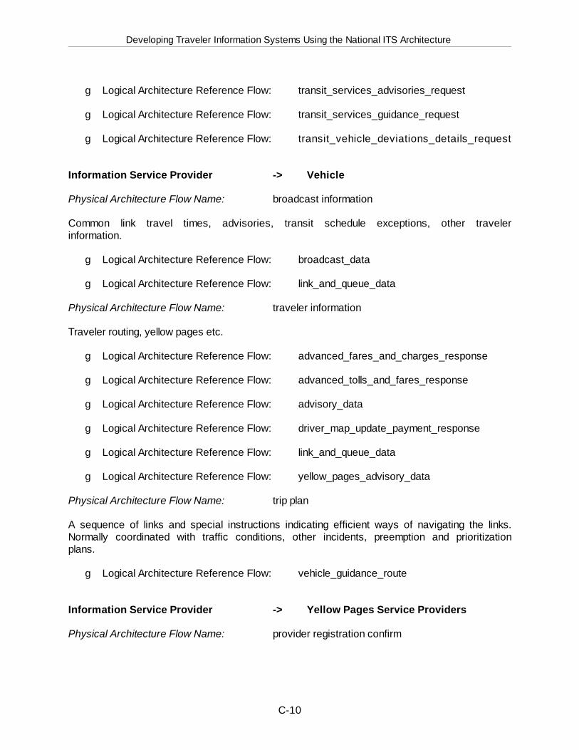
Developing Traveler Information Systems Using the National ITS Architecture
C-10
g Logical Architecture Reference Flow: transit_services_advisories_request
g Logical Architecture Reference Flow: transit_services_guidance_request
g Logical Architecture Reference Flow: transit_vehicle_deviations_details_request
Information Service Provider -> Vehicle
Physical Architecture Flow Name: broadcast information
Common link travel times, advisories, transit schedule exceptions, other travelerinformation.
g Logical Architecture Reference Flow: broadcast_data
g Logical Architecture Reference Flow: link_and_queue_data
Physical Architecture Flow Name: traveler information
Traveler routing, yellow pages etc.
g Logical Architecture Reference Flow: advanced_fares_and_charges_response
g Logical Architecture Reference Flow: advanced_tolls_and_fares_response
g Logical Architecture Reference Flow: advisory_data
g Logical Architecture Reference Flow: driver_map_update_payment_response
g Logical Architecture Reference Flow: link_and_queue_data
g Logical Architecture Reference Flow: yellow_pages_advisory_data
Physical Architecture Flow Name: trip plan
A sequence of links and special instructions indicating efficient ways of navigating the links.Normally coordinated with traffic conditions, other incidents, preemption and prioritizationplans.
g Logical Architecture Reference Flow: vehicle_guidance_route
Information Service Provider -> Yellow Pages Service Providers
Physical Architecture Flow Name: provider registration confirm
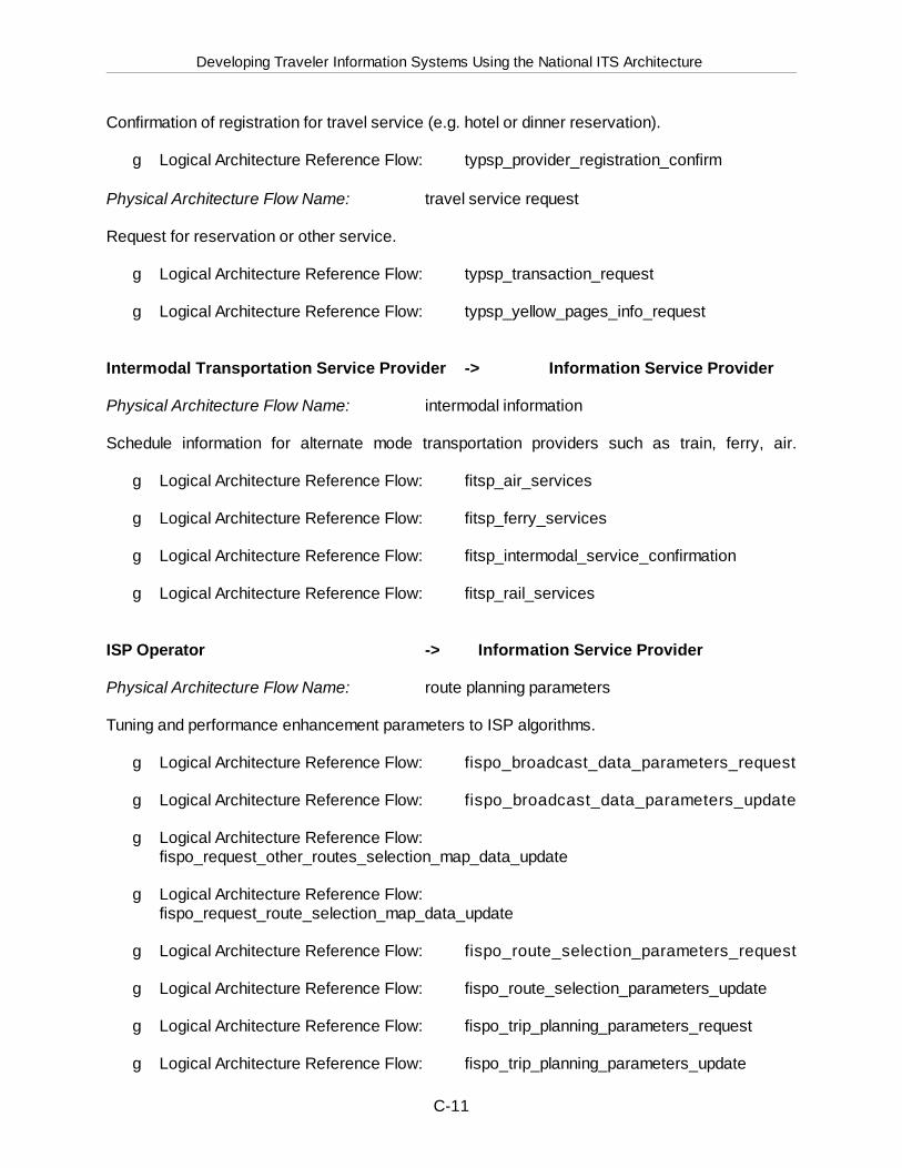
Developing Traveler Information Systems Using the National ITS Architecture
C-11
Confirmation of registration for travel service (e.g. hotel or dinner reservation).
g Logical Architecture Reference Flow: typsp_provider_registration_confirm
Physical Architecture Flow Name: travel service request
Request for reservation or other service.
g Logical Architecture Reference Flow: typsp_transaction_request
g Logical Architecture Reference Flow: typsp_yellow_pages_info_request
Intermodal Transportation Service Provider -> Information Service Provider
Physical Architecture Flow Name: intermodal information
Schedule information for alternate mode transportation providers such as train, ferry, air.
g Logical Architecture Reference Flow: fitsp_air_services
g Logical Architecture Reference Flow: fitsp_ferry_services
g Logical Architecture Reference Flow: fitsp_intermodal_service_confirmation
g Logical Architecture Reference Flow: fitsp_rail_services
ISP Operator -> Information Service Provider
Physical Architecture Flow Name: route planning parameters
Tuning and performance enhancement parameters to ISP algorithms.
g Logical Architecture Reference Flow: fispo_broadcast_data_parameters_request
g Logical Architecture Reference Flow: fispo_broadcast_data_parameters_update
g Logical Architecture Reference Flow:fispo_request_other_routes_selection_map_data_update
g Logical Architecture Reference Flow: fispo_request_route_selection_map_data_update
g Logical Architecture Reference Flow: fispo_route_selection_parameters_request
g Logical Architecture Reference Flow: fispo_route_selection_parameters_update
g Logical Architecture Reference Flow: fispo_trip_planning_parameters_request
g Logical Architecture Reference Flow: fispo_trip_planning_parameters_update
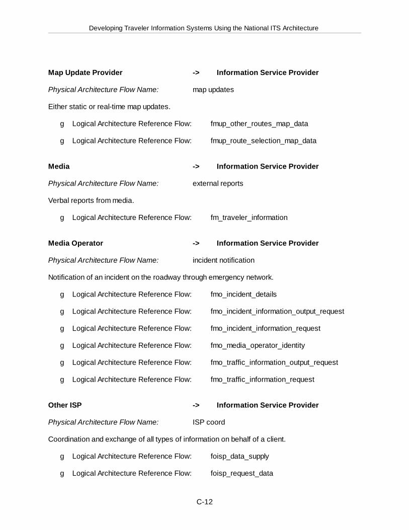
Developing Traveler Information Systems Using the National ITS Architecture
C-12
Map Update Provider -> Information Service Provider
Physical Architecture Flow Name: map updates
Either static or real-time map updates.
g Logical Architecture Reference Flow: fmup_other_routes_map_data
g Logical Architecture Reference Flow: fmup_route_selection_map_data
Media -> Information Service Provider
Physical Architecture Flow Name: external reports
Verbal reports from media.
g Logical Architecture Reference Flow: fm_traveler_information
Media Operator -> Information Service Provider
Physical Architecture Flow Name: incident notification
Notification of an incident on the roadway through emergency network.
g Logical Architecture Reference Flow: fmo_incident_details
g Logical Architecture Reference Flow: fmo_incident_information_output_request
g Logical Architecture Reference Flow: fmo_incident_information_request
g Logical Architecture Reference Flow: fmo_media_operator_identity
g Logical Architecture Reference Flow: fmo_traffic_information_output_request
g Logical Architecture Reference Flow: fmo_traffic_information_request
Other ISP -> Information Service Provider
Physical Architecture Flow Name: ISP coord
Coordination and exchange of all types of information on behalf of a client.
g Logical Architecture Reference Flow: foisp_data_supply
g Logical Architecture Reference Flow: foisp_request_data
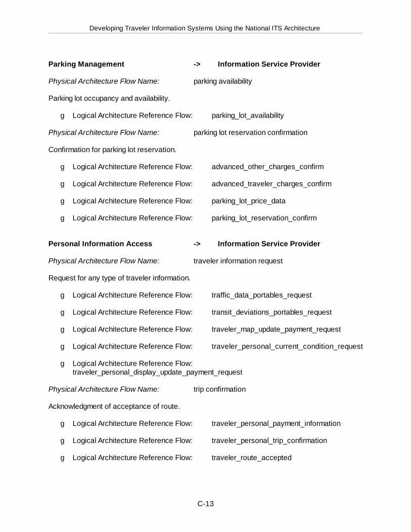
Developing Traveler Information Systems Using the National ITS Architecture
C-13
Parking Management -> Information Service Provider
Physical Architecture Flow Name: parking availability
Parking lot occupancy and availability.
g Logical Architecture Reference Flow: parking_lot_availability
Physical Architecture Flow Name: parking lot reservation confirmation
Confirmation for parking lot reservation.
g Logical Architecture Reference Flow: advanced_other_charges_confirm
g Logical Architecture Reference Flow: advanced_traveler_charges_confirm
g Logical Architecture Reference Flow: parking_lot_price_data
g Logical Architecture Reference Flow: parking_lot_reservation_confirm
Personal Information Access -> Information Service Provider
Physical Architecture Flow Name: traveler information request
Request for any type of traveler information.
g Logical Architecture Reference Flow: traffic_data_portables_request
g Logical Architecture Reference Flow: transit_deviations_portables_request
g Logical Architecture Reference Flow: traveler_map_update_payment_request
g Logical Architecture Reference Flow: traveler_personal_current_condition_request
g Logical Architecture Reference Flow: traveler_personal_display_update_payment_request
Physical Architecture Flow Name: trip confirmation
Acknowledgment of acceptance of route.
g Logical Architecture Reference Flow: traveler_personal_payment_information
g Logical Architecture Reference Flow: traveler_personal_trip_confirmation
g Logical Architecture Reference Flow: traveler_route_accepted
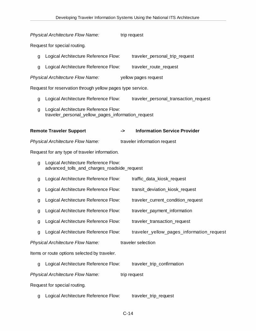
Developing Traveler Information Systems Using the National ITS Architecture
C-14
Physical Architecture Flow Name: trip request
Request for special routing.
g Logical Architecture Reference Flow: traveler_personal_trip_request
g Logical Architecture Reference Flow: traveler_route_request
Physical Architecture Flow Name: yellow pages request
Request for reservation through yellow pages type service.
g Logical Architecture Reference Flow: traveler_personal_transaction_request
g Logical Architecture Reference Flow: traveler_personal_yellow_pages_information_request
Remote Traveler Support -> Information Service Provider
Physical Architecture Flow Name: traveler information request
Request for any type of traveler information.
g Logical Architecture Reference Flow: advanced_tolls_and_charges_roadside_request
g Logical Architecture Reference Flow: traffic_data_kiosk_request
g Logical Architecture Reference Flow: transit_deviation_kiosk_request
g Logical Architecture Reference Flow: traveler_current_condition_request
g Logical Architecture Reference Flow: traveler_payment_information
g Logical Architecture Reference Flow: traveler_transaction_request
g Logical Architecture Reference Flow: traveler_yellow_pages_information_request
Physical Architecture Flow Name: traveler selection
Items or route options selected by traveler.
g Logical Architecture Reference Flow: traveler_trip_confirmation
Physical Architecture Flow Name: trip request
Request for special routing.
g Logical Architecture Reference Flow: traveler_trip_request

Developing Traveler Information Systems Using the National ITS Architecture
C-15
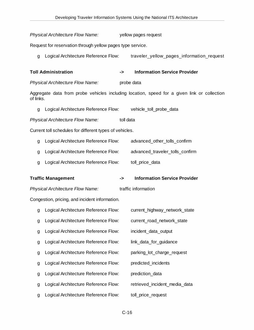
Developing Traveler Information Systems Using the National ITS Architecture
C-16
Physical Architecture Flow Name: yellow pages request
Request for reservation through yellow pages type service.
g Logical Architecture Reference Flow: traveler_yellow_pages_information_request
Toll Administration -> Information Service Provider
Physical Architecture Flow Name: probe data
Aggregate data from probe vehicles including location, speed for a given link or collectionof links.
g Logical Architecture Reference Flow: vehicle_toll_probe_data
Physical Architecture Flow Name: toll data
Current toll schedules for different types of vehicles.
g Logical Architecture Reference Flow: advanced_other_tolls_confirm
g Logical Architecture Reference Flow: advanced_traveler_tolls_confirm
g Logical Architecture Reference Flow: toll_price_data
Traffic Management -> Information Service Provider
Physical Architecture Flow Name: traffic information
Congestion, pricing, and incident information.
g Logical Architecture Reference Flow: current_highway_network_state
g Logical Architecture Reference Flow: current_road_network_state
g Logical Architecture Reference Flow: incident_data_output
g Logical Architecture Reference Flow: link_data_for_guidance
g Logical Architecture Reference Flow: parking_lot_charge_request
g Logical Architecture Reference Flow: predicted_incidents
g Logical Architecture Reference Flow: prediction_data
g Logical Architecture Reference Flow: retrieved_incident_media_data
g Logical Architecture Reference Flow: toll_price_request
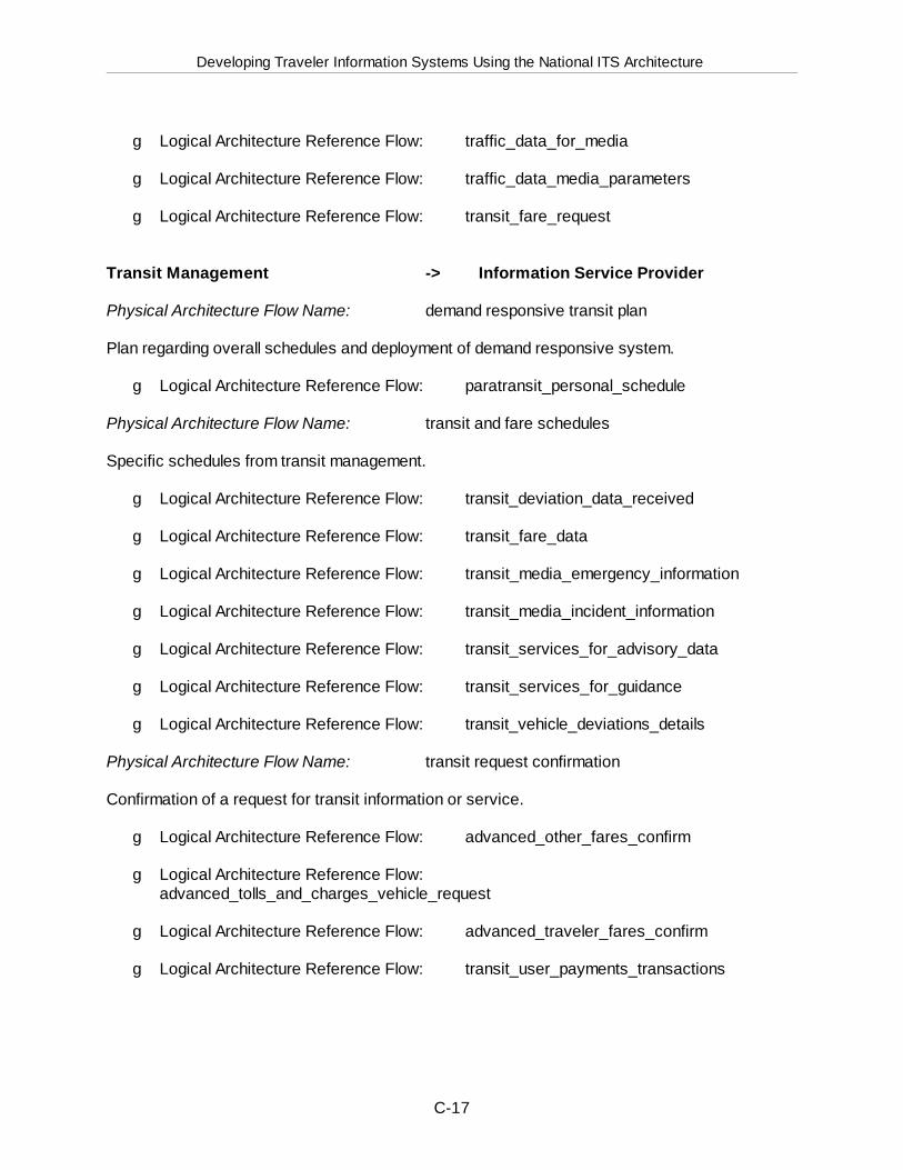
Developing Traveler Information Systems Using the National ITS Architecture
C-17
g Logical Architecture Reference Flow: traffic_data_for_media
g Logical Architecture Reference Flow: traffic_data_media_parameters
g Logical Architecture Reference Flow: transit_fare_request
Transit Management -> Information Service Provider
Physical Architecture Flow Name: demand responsive transit plan
Plan regarding overall schedules and deployment of demand responsive system.
g Logical Architecture Reference Flow: paratransit_personal_schedule
Physical Architecture Flow Name: transit and fare schedules
Specific schedules from transit management.
g Logical Architecture Reference Flow: transit_deviation_data_received
g Logical Architecture Reference Flow: transit_fare_data
g Logical Architecture Reference Flow: transit_media_emergency_information
g Logical Architecture Reference Flow: transit_media_incident_information
g Logical Architecture Reference Flow: transit_services_for_advisory_data
g Logical Architecture Reference Flow: transit_services_for_guidance
g Logical Architecture Reference Flow: transit_vehicle_deviations_details
Physical Architecture Flow Name: transit request confirmation
Confirmation of a request for transit information or service.
g Logical Architecture Reference Flow: advanced_other_fares_confirm
g Logical Architecture Reference Flow: advanced_tolls_and_charges_vehicle_request
g Logical Architecture Reference Flow: advanced_traveler_fares_confirm
g Logical Architecture Reference Flow: transit_user_payments_transactions
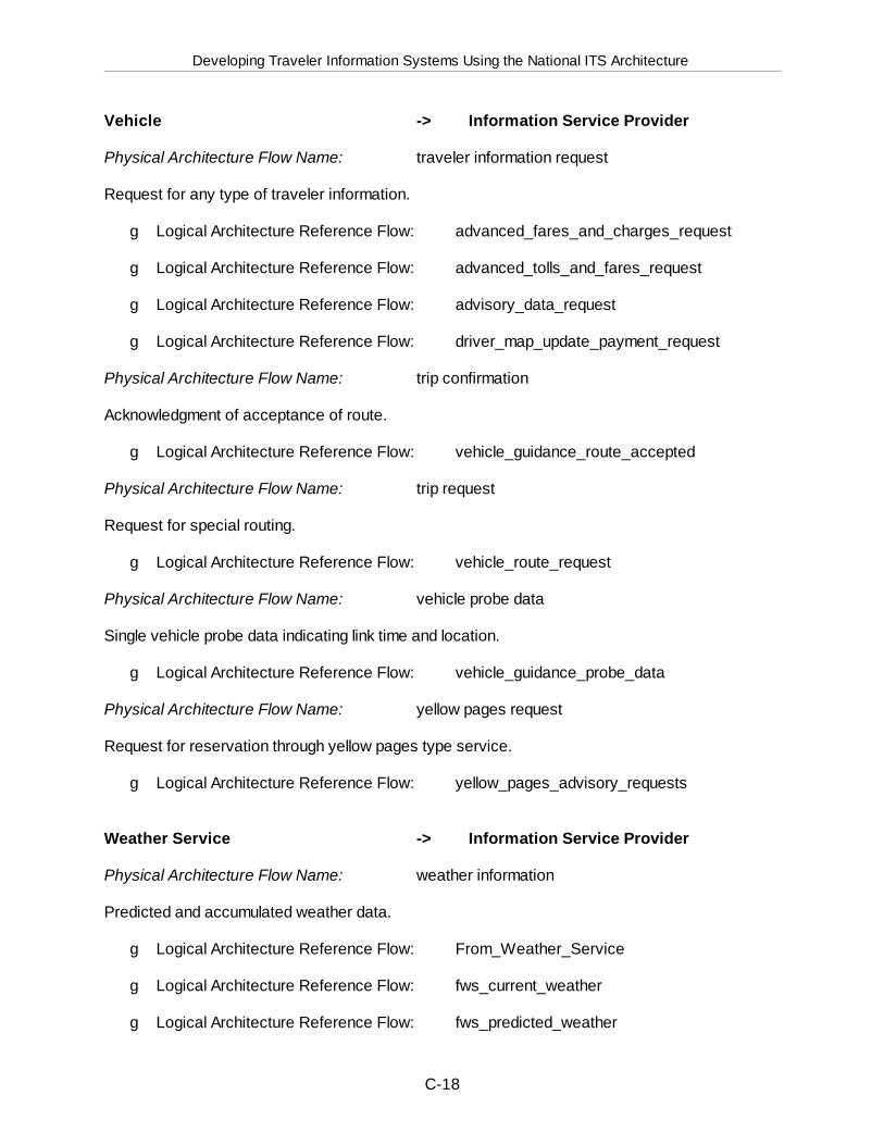
Developing Traveler Information Systems Using the National ITS Architecture
C-18
Vehicle -> Information Service Provider
Physical Architecture Flow Name: traveler information request
Request for any type of traveler information.
g Logical Architecture Reference Flow: advanced_fares_and_charges_request
g Logical Architecture Reference Flow: advanced_tolls_and_fares_request
g Logical Architecture Reference Flow: advisory_data_request
g Logical Architecture Reference Flow: driver_map_update_payment_request
Physical Architecture Flow Name: trip confirmation
Acknowledgment of acceptance of route.
g Logical Architecture Reference Flow: vehicle_guidance_route_accepted
Physical Architecture Flow Name: trip request
Request for special routing.
g Logical Architecture Reference Flow: vehicle_route_request
Physical Architecture Flow Name: vehicle probe data
Single vehicle probe data indicating link time and location.
g Logical Architecture Reference Flow: vehicle_guidance_probe_data
Physical Architecture Flow Name: yellow pages request
Request for reservation through yellow pages type service.
g Logical Architecture Reference Flow: yellow_pages_advisory_requests
Weather Service -> Information Service Provider
Physical Architecture Flow Name: weather information
Predicted and accumulated weather data.
g Logical Architecture Reference Flow: From_Weather_Service
g Logical Architecture Reference Flow: fws_current_weather
g Logical Architecture Reference Flow: fws_predicted_weather
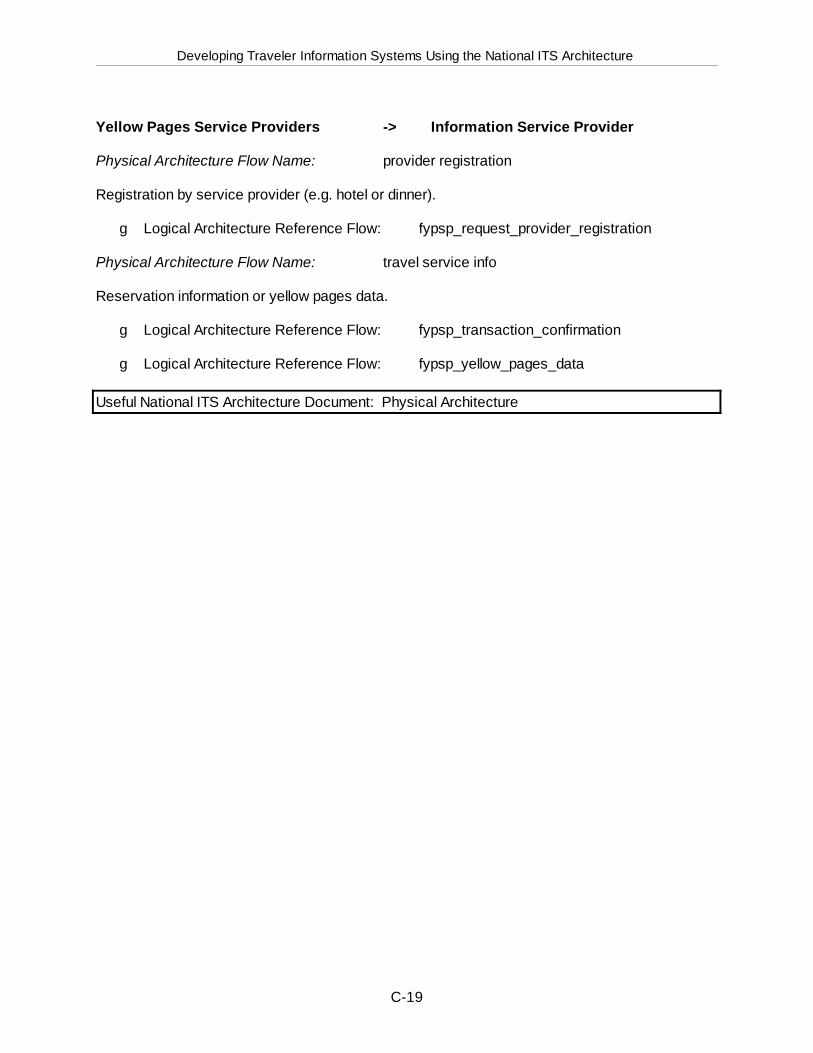
Developing Traveler Information Systems Using the National ITS Architecture
C-19
Yellow Pages Service Providers -> Information Service Provider
Physical Architecture Flow Name: provider registration
Registration by service provider (e.g. hotel or dinner).
g Logical Architecture Reference Flow: fypsp_request_provider_registration
Physical Architecture Flow Name: travel service info
Reservation information or yellow pages data.
g Logical Architecture Reference Flow: fypsp_transaction_confirmation
g Logical Architecture Reference Flow: fypsp_yellow_pages_data
Useful National ITS Architecture Document: Physical Architecture
Developing Traveler Information Systems Using the National ITS Architecture
D-1
Appendix D. National ITS Architecture Products
Provided below is a brief overview of all documents that are part of the National ITSArchitecture.
Vision Statement Written in “magazine style,” the Vision Statement sketches a numberof possible scenarios of ITS development over the next 20 years. It describes howtravelers and system operators may be able to use and benefit from ITS technologies intheir day-to-day activities. While the Vision Statement is not a technical document, itdoes describe the potential impact of ITS technologies on the management of thenation’s transportation system.
Mission Definition The first of the technical documents, the Mission Definition covers abroad range of ITS-related issues. It contains the overall mission of ITS deployment, aswell as the operational concept, which deals with specific ITS goals and objectives; ITSuser groups and other stakeholders; ITS user services; and potential sources forfunding, operations and maintenance. The document also defines operationalrequirements at the system level, user requirements, performance requirements, andprogram requirements.
These concepts are important aspects of the National Architecture throughout thedeployment process, since they provide the overall direction for the ITS program. Constant evaluation of a region’s ITS deployment against the national goals andobjectives will ensure that regional ITS deployment is compatible with the philosophy ofthe National Architecture. The Mission Definition document is important for those thatare involved with the initial concepts definition of an ITS system for a particular region.
Logical Architecture The Logical Architecture document contains three volumes:Description (Volume 1), Process Specifications (Volume 2), and Data Dictionary (Volume3). These documents present a functional view of the ITS user services, containdiagrams that show processes and data flows among them, and define data elements,respectively.
Physical Architecture The Physical Architecture document describes the transportationand communications layers resulting from the partitioning of the processes within thelogical architecture, presents architecture flow diagrams that show data passing amongphysical subsystems, and provides characteristics and constraints on the data flows.
Theory Of Operations This document provides a detailed narrative of the manner inwhich the architecture supports the ITS user services, described in the MissionDefinition. It is a technical document, intended for engineers, operators, and othersinvolved detailed systems design.
Traceability Document The Traceability Document is a technical document that is usedin conjunction with and throughout the development of the Logical and Physical
Developing Traveler Information Systems Using the National ITS Architecture
D-2
Architectures. It lists all the User Service Requirements (USR), which constitute thehighest-level functional specifications for ITS, as provided by the U.S. Department ofTransportation. In several tables, these USRs are mapped to the various logical andphysical components of an ITS system. The document should be used primarily bythose involved in detailed design.
Implementation Strategy The Implementation Strategy document ties the elements theNational Architecture together, and is intended to assist ITS implementors at all levelswith cost-effective, efficient ITS deployment.
Standards Development Plan This document discusses the issues that are involved inthe development of system interface standards. It is primarily intended for StandardsDevelopment Organizations and system designers, and will be important at theintegration step in the Systems Engineering Process.
Standards Requirements This is a set of 12 Standards Requirements Packages thatpresents detailed data flow and interface information pertaining to the priority standardspackages that need to be developed to implement the architecture. It, too, is primarilyintended for Standards Development Organizations and system designers, and will beimportant at the integration step in the Systems Engineering Process.
Evaluatory Design The Evaluatory Design document is intended to evaluate theNational Architecture’s performance, benefits, and costs for three conceptual scenariosat various points in time. The scenarios consist of “typical” deployment environments:urban, inter-urban, and rural. The entire document will assist you in developing anevaluation methodology for the architecture that you have developed for your particularregion.
Communications Document This document provides a thorough analysis of thecommunications requirements of the National Architecture, and ITS in general, andincludes a discussion of options for implementing various communications links. Withthe latest version of the National Architecture, an addendum to this document waspublished, detailing requirements for the Highway-Rail Intersections User Service. It isan important document for those involved in detailed design and integration during theSystems Engineering Process.
Risk Analysis This document presents an analysis of potential critical risks that maydelay or prevent the deployment of ITS technologies, and recommends mitigation planswhich will eliminate of reduce these risks to the deployment process. It is intended forimplementors that are involved with the details of ITS deployment in their region,throughout the development of the Regional Architecture.
Cost Analysis The Cost Analysis document has two purposes. First, it develops a high-level cost estimate of the expenditures that are associated with implementing ITScomponents. Second, it is a costing tool for implementers, by providing unit prices andsystems costs of ITS subsystems. There is significant correlation between the Cost
Developing Traveler Information Systems Using the National ITS Architecture
D-3
Analysis and the Evaluatory Design documents; the Cost Analysis is based largely onthe assumptions made for the three deployment scenarios (urban, inter-urban, andrural). The latest version of the National Architecture documents contains anaddendum to the Cost Analysis, accounting for the Highway-Rail Intersection UserService. This is an important document for those involved in planning and design, andcould be useful to those responsible for project management in the SystemsEngineering Process, including funding and procurement.
Developing Traveler Information Systems Using the National ITS Architecture
D-4
Performance and Benefits Study This document assesses the technical performance ofthe National Architecture on a number of system-level and operational-level criteria. Itcould be helpful in supporting the case for ITS deployment, as it provides a measure ofthe degree to which ITS can help achieve some regional transportation goals.
Evaluation Results This document contains a concise summary of the variousevaluations that were performed in five other National Architecture documents:Evaluatory Design, Communications Analysis, Cost Analysis, Performance andBenefits, and Risk Analysis.
Executive Summary Provides an overview of the most important aspects of the NationalArchitecture, most notably the Logical and Physical Architectures.
Developing Traveler Information Systems Using the National ITS Architecture
E-1
Appendix E. Traveler Information SystemTechnologies
E.1 Overview A brief list of technologies discussed in this appendix are listed below:
Pre-Trip Information Technologies (Section E.2)Home and Office Computer-Based Systems (Internet, Electronic Bulletin Board Service, Videotex)Telephone-Based Systems (Traveler Advisory Telephone, Loop Tape System, Voice Response System)Television-Based Systems (Broadcast Television, Teletext, Cable Television, Interactive Television)
En route Information Technologies (Section E.3)Roadway-Based Systems (Variable Message Signs, Highway Advisory Radio, Portable Systems)Station-Based Systems (Public Announcement Systems, Display Monitors, Message Boards, Kiosks)Personal-Based Systems (Personal Digital Assistants, Pagers)
In-Vehicle Technologies (Section E.4)In-Vehicle (Automobile) Systems (AM Radio, Static Route Guidance, Dynamic Route Guidance, Mayday)In-Transit Vehicle Systems (In-Vehicle Message Boards, Automatic Annunciation Systems)
E.2 Pre-Trip Information TechnologiesComputer-based, telephone based, and television-based traveler information systems arediscussed below.
E.2.1 Home and Office Computer-Based SystemsComputer-based pre-trip traveler information, including the Internet, Electronic Bulletin BoardServices, and Videotex are discussed in this section. These technologies provide access to pre-trip information from the home and office.
E.2.1.1 InternetOn-line services to access the Internet represent a growing method for disseminating pre-triptraveler information. The Internet originally began as a small, specialized network connectingscientists to distant computers and to each other, around the country and around the world. TheInternet can be accessed from home or office computers and PDAs.
On the Internet, dozens of different types of computers using the same telecommunicationtechnology. The Internet is accessed using commercially available computer programs called webbrowsers.
A wide variety of organizations have developed, or are currently developing Internet-compatiblesystems to provide roadway and transit related transportation services and information for majormetropolitan areas around the country. Types of information available include:
g Comprehensive bus and rail system schedule information, and details on fare paymentsystems
g Traffic speeds
Developing Traveler Information Systems Using the National ITS Architecture
E-2
g Color maps showing locations of light, moderate and heavy traffic congestion, as well aslocations of stopped traffic along major roadways.
g Construction information
g Real-time photos of traffic conditions
g Incident information
E.2.1.2 Electronic Bulletin Board ServicesElectronic Bulletin Board Services are two-way information system that use computer terminals inthe home or office to request and display traveler information. Information can be disseminatedto the public through a commercial provider such as America On Line, CompuServe, etc., or theuser can directly log in by using a telephone number. Another option includes posting travelerinformation directly to subscribers. For example, commercial trucking companies can beinformed in advance about construction and affected routes on a weekly or biweekly (fixed timeintervals) basis. These services can be provided for free or at a nominal charge.
E.2.1.3 VideotexVideotex is a consumer oriented, two-way information system that uses computer terminals in thehome or office to request and display information about products and services. It is an on-linecomputer-based travel information system that provides routing information, though primarilyusing audiotex technology (i.e., the push button phone is the primary means of accessing thedatabase). To request routing information, the user enters the origin and destination telephonenumbers via a touch tone phone and receives the directions via synthesized voice, fax, or videodisplay.
E.2.2 Telephone-Based SystemsTelephone-based pre-trip traveler information systems, including Traveler Advisory Telephoneand Automated Trip Planning Services, are discussed in this section. While these technologiescan be used to provide access to pre-trip information, use of a touch-tone cellular telephoneallows travelers to inquire about current travel conditions, or to plan the next leg of a trip, whiletraveling en route to a specific destination.
E.2.2.1 Traveler Advisory TelephoneTraveler Advisory Telephone (TAT)— also known as audiotex— can provide up-to-the-minutetraffic information in the form of voice messages delivered to motorists before or during a trip. Traveler advisory telephone functions include the ability to provide traffic conditions, real timetraffic information for trip planning, public transit information (i.e., transit fares and schedules), andoperational information (i.e., roadway construction and ramp closures) capabilities. Users oftraveler advisory telephone can access information simply by dialing a telephone number eitherfrom their home, office, or automobile. Upon calling a TAT system, the user is guided throughvoice menus enabling them to access the desired information.

Developing Traveler Information Systems Using the National ITS Architecture
E-3

Developing Traveler Information Systems Using the National ITS Architecture
E-4
E.2.2.2 Loop Tape SystemLoop tape systems play pre-recorded messages continuously and cannot accept any interactivecommands from the callers. This is a basic telephone information system intended for verysimple applications, or as an alternative service for users who do not have the touch-tonetelephone access. Pre-recorded messages can also be regularly updated and stored for use bythe loop tape system.
E.2.2.3 Voice Response SystemA voice response system (VRS) provides callers with interactive voice response andvoice messaging service. A voice response system interfaces between the telephonenetwork and host application. Functions provided can include speaking voice menus tocallers, prompting for caller inputs (touch-tone signals), and translating the receivedtouch-tone signals into digital data. The digital data is transmitted to the hostapplication, which can then use the voice response system to provide synthesized orpre-recorded voice messages to the caller.
E.2.3 Television-Based SystemsTelevision-based pre-trip traveler information systems, including the Television Media, Teletext,Cable Television, and Interactive Television are discussed in further detail in this section. Thesetechnologies provide access for travelers at the home, workplace, hotels, and other publicenvironments which may be equipped with television.
E.2.3.1 Broadcast Television MediaAn ITS-based system is a repository for significant amounts of real-time information on trafficflow conditions and incidents, transit operations, and construction/maintenance activities. Itshould therefore include some form of interface for filtering this information and providing up-to-the-minute data to television and radio stations, and private entities (Information serviceProviders), either automatically or upon inquiry. Possible interfaces include:
g Teletype Network - Text information on current traffic flow conditions (e.g., averagespeeds, estimated travel times, congested areas, incident locations) is periodicallytransmitted to dedicated printers or FAX machines at the various stations. One procedureis called “rip and read,” where relatively final copy is provided. Another method is to justprovide traffic flow information in a standardized format that can then be used bybroadcasters in preparing their traffic reports.
g Workstations - This is similar to the teletype network, but now the television and radiostations have workstations and two-way communications, permitting them to directly querythe ITS system. With this form of media interface, the ITS must be capable of limiting thedata to which the stations have access.
g Color Graphics - This option is identical to the workstation alternative, except that a high-resolution color monitor is included for showing real-time graphic displays of conditionsthroughout the roadway and transit network (e.g., different colors representing variousspeed or travel time thresholds, and adherence of transit routes). These real-time displaysmay also be televised over existing stations and/or a dedicated traffic channel (e.g., cable),
Developing Traveler Information Systems Using the National ITS Architecture
E-5
thereby permitting residents to alter their travel plans (if necessary) before they becomemotorists and commit themselves to a particular route or mode.
g Video Information - CCTV images can be transmitted for locations where incidents arepresent or for selected freeway locations. The number of images available to the mediawould depend on the resources available to multiplex the data for transmission to the mediaand the level of manipulation (switching, number of monitors) the media outlet(s) would haveavailable. A basic issue is whether video images are appropriate for rebroadcast over thepublic airways. CT DOT provides a video interface to the media, but with a 30 seconddelay that permits system operators to cut off the video feed should the current images beinappropriate (e.g., incident with serious injuries).
There are several additional issues associated with the dissemination of information to the mediaand the public which need to be considered. These include the following:
g Control of presentation format - If a data stream is sent to the media and other InformationService Providers (ISPs), one can expect that they will use this information to provide somevalue added service for their clients. The same data can be used very differently bydifferent ISPs, and the public agency generating the data may not have control over thesepresentations, abbreviations, frequency of broadcast, etc. unless constrained byagreement.
g Consistency of information presentations - The same information can be interpreted bydifferent agencies and ISPs in different ways. This has been an important considerationfor other advanced transportation management centers. If freeway speeds are broadcast,then what constitutes “congestion” can become subject to interpretation. On the otherhand, if Level of Service is sent, does this have any real meaning to the public?
g Protection of confidential information - Video images and incident reports may containspecific information (license plate number, names, severity of injuries, etc.) which mayneed to be filtered depending upon the agency receiving the information. It must beassumed that all data sent can and will be used by the media to meet their needs topromote their service.
g Impact on local roadways - If diversion recommendations are being made independently bythe information service provider, its impact may not have been planned, and may becounter productive to the agencies’ traffic management plan.
g Impact on toll and transit operations (revenue) - If inaccurate traffic information istransmitted to the public, it may adversely impact the revenue collection on the primaryfacility. Information about blockages/closures at toll facilities or transit networks will impactrevenue as travelers choose alternate routes or modes. This is a proper function for thetransportation management facility, but can lead to conflicting goals (i.e., generate revenuevs. accurate customer information).
g Accuracy and availability of the data - Transportation management systems have oftenbeen notorious for poor maintenance of surveillance and detection components. As real-time information is presented to the public, inaccurate data will be immediately apparent,and public agencies will have to allocate significantly more resources to maintenance of thesurveillance subsystem. As more traveler information is provided to the public, it isreasonable that the public will begin to demand more timely and accurate information, with

Developing Traveler Information Systems Using the National ITS Architecture
E-6
less and less tolerance or outages of system components, data collection elements, ordissemination elements.
Developing Traveler Information Systems Using the National ITS Architecture
E-7
E.2.3.2 TeletextTeletext technology uses the Vertical Blanking Interval (VBI) portion of the TV channel’s bandwidthto transmit traveler information. The VBI is the black horizontal line located on the lower part ofthe TV screen, and can be seen when the TV vertical hold knob is adjusted. The information canbe transmitted in conjunction with commercial TV channels or cable TV.
Teletext is a promising media for providing visual and up-to-date information on demand to thetraveler at home. By providing a relatively simple means of obtaining traffic and transit informationfor trip planning purposes, the chances for user acceptance are improved. To view thetransmitted information, observers must have a standard television equipped with a World SystemTeletext (WST) chip— the same device used to see the closed-captioned features available forthe hearing impaired. Though currently only a relatively small percentage of televisions in the U.S.are equipped to receive teletext transmissions, the trend in the television manufacturing industryis to provide teletext reception as a standard feature. As televisions are replaced over the nextfew years, the potential audience for teletext will increase significantly.
Once city is currently using this technology to distribute information to the local media. Theinformation — which includes schematic maps, lane closures, color indications of congestionlevels, incident locations, and variable message signs— is transmitted over low power television,(UHF Channel 54) within the vertical blanking interval; and is currently received by the three majortelevision networks within the City, the City’s mainstream newspaper, and five radio stations. These partners pay a one-time software fee.
E.2.3.3 Cable Television (CATV) ChannelsTelevision can aid in disseminating traveler information through community access or cabletelevision channels (CATV). CATV can transmit graphical, textual, and audible information duringspecific time periods or 24 hours per day if allotted a dedicated ”traffic channel.” This form oftraveler information requires a cooperative effort between the transportation agency distributingthe information and the local cable television franchise. In areas where penetration of cable in themarket is high, CATV can be an extremely cost-effective way to disseminate information. Currently, cable television is not found extensively in rural areas. However, cable services areexpanding and there are many small urban areas with cable access where it may be appropriateto transmit information.
Information which may be made available may include:
g An overview map of the city or region with color-coded highway segments which indicatesthe current speed at which traffic is moving, and a second overview map which utilizesicons to place incident locations.
g A pre-recorded message can inform viewers what the color coding means and to staytuned for more detailed information.
g The system can report individual incidents and provide a detailed incident location map aswell as textual descriptions.
Developing Traveler Information Systems Using the National ITS Architecture
E-8
g Live video feeds matching the incident and narration describe the nature of the incidentsavailable from the incident map.
g A commercial break provided by the local cable TV station follows incident reports.
g A scrolling text bulletin board which provides special traffic and transit advisories.
E.2.3.4 Interactive TelevisionInteractive television is similar to cable television and broadcast television in that real-timeinformation is made available to travelers via the TV medium. The major difference is that, whilecable and broadcast television simply presents the information on a programmed and repetitivebasis, interactive television allows a traveler to directly obtain specific information at any point intime.
Information which may be made available through an interactive channel may include:
g Incident Information - From an overview map, users could request more information onparticular incidents by selecting one of the pre-defined zones in the overview map. Theincident in the selected zone was described in a more detailed street map with an iconindicating the location and textual descriptions of the incident.
g Highway Speed Map - By selecting this function, the user could see a stylized overviewmap of the city or region in which the color coded road segments indicate the current trafficspeed on the major highways, with smaller icons pointing out the location of incidents. Apre-recorded narration explained the legends and the meaning of color coding scheme.
g Public Transit - By selecting this function, the user gained access to several presentationsincluding a description of the transit (bus and subway) system, the transit frequency tablesfor appropriate transit lines, park and ride lot status, and directions (i.e., a presentation ofwhere the park and ride lots are and how to drive to them), and wide area travelerinformation on passenger rail, buses, and airline information.
g Directions to Major Arenas - Users could access the direction service for locations wheresporting and special events occur. Users can select a destination and received a slidepresentation with audio narration on how to travel to the destination.
g Restaurant and Area Attractions - Users could view restaurants by cuisine and other areaattractions, select a destination, and receive a slide presentation with audio narration onhow to travel to the destination.
g Hotel Services - To make the complete information service of value to the user, hotelconveniences such as the in-hotel stores and services can also be made available.
g Weather - National and local weather reports of current and forecast conditions.
g Yellow Page Information - This service would allow users to perform on-screen queries ona comprehensive geocoded electronic yellow page database. The database would bedesigned to contain listings of interest to the traveler; thus, it had restaurants, other hotels,car repair stores, and other categories. The requested information could be generatedand printed out on the computer in the hotel.

Developing Traveler Information Systems Using the National ITS Architecture
E-9
Developing Traveler Information Systems Using the National ITS Architecture
E-10
E.3 En Route Information TechnologiesRoadway-based, in-vehicle-based, in-transit vehicle based, station-based, and personal based systemsfor disseminating traveler information en route are discussed in further detail in this section.
E.3.1 Roadway-Based SystemsVariable Message Signs (VMS) and Highway Advisory Radio (HAR) systems technologiesrepresent the two basic technologies currently available to provide drivers with real-time and staticinformation from roadside equipment while en route.
E.3.1.1 Variable Message SignsVariable message signs (VMS) provide dynamic information to motorists regarding a variety ofconditions, including:
g Congestion - Variable message signs can be used to warn motorists of congestion that liesahead as a result of an incident, bottleneck, or special event. The VMS can also be usedto provide warnings when unexpected queuing occurs in areas of restricted sight distancesuch as around a curve or over a road crest.
g Diversion - Variable message signs can be used to inform motorists of available orrequired alternative routes.
g General Guidance Information - Variable message signs can be used to provide directionsand information on ways to obtain additional information through other means (e.g., radio).
g Maintenance and Construction Work Sites - Variable message signs can be used to warnmotorists of lane closures in order to avoid abrupt weaving. End of queue warnings andalternative route information can also be provided to motorists approaching work sites.
g Roadway Status - Variable Message Signs are used extensively to provide informationregarding the status of roadways such as environmental conditions (i.e., snow, fog) andspecial operational features (HOV lanes, reversible lanes, drawbridges).
Variable message signs (or message boards) can be used at transit stations to provide scheduleinformation (e.g., arrivals, departures, status), on platforms to identify the arrival time anddestination of the next vehicle, and on vehicles themselves to identify the next stop and estimatedtime before arrival. This functionality is discussed in a subsequent section.
Variable Message Sign TypesSeveral different types of variable message signs have been developed. One is the “blank-out”sign in which a single message can be turned on or off as conditions require. Signs of this typeare applicable to Highway Advisory Radio sites where the signs are turned on in advance of aparticular segment whenever radio messages are being broadcast. When only a few fixedmessages are needed at a particular site, a rotating drum sign— consisting of a three or six-sidedprism for each line of the message — can be used.
The most flexible type of VMS is the matrix sign. The desired legend is displayed by turning on oroff individual pixels. Matrix options include:
Developing Traveler Information Systems Using the National ITS Architecture
E-11
g Character Matrix - An individual module is provided for each character (letter). The letterspacing and maximum letter width is fixed.
g Line Matrix - A single matrix is provided for each line. This allows proportional spacingbetween letters, but limited graphics capability.
g Full Matrix - There are no built-in divisions between letters or lines. This configurationallows the greatest flexibility in the size and stroke of letters plus graphic symbols.
E.3.1.2 Highway Advisory RadioHighway advisory radio (HAR) systems, usually located at roadside stations, communicate locallyrelevant traveler information to all vehicles in the vicinity of the station. They are commonly"broadcast only" (infrastructure to vehicle) systems using the conventional AM broadcast bandradio in the vehicle. HAR can provide travelers with information regarding construction activities,special events, road closures or hazards, traffic congestion, incidents, alternate route guidance,and traveler information concerning local attractions. The transmission range of traditional HARsystems is limited to a few miles.
HAR were initially authorized for use in the United States by the Federal CommunicationsCommission (FCC) in 1977. These systems are also used by airports, train and bus stations,national, state and regional parks, counties and local municipalities, sports arenas, conventioncenters, and other entertainment venues, for disseminating traveler information. HAR uses theAM radio frequency spectrum, and almost all privately owned automobiles are equipped with abroadcast band AM radio. Until approximately two years ago, the AM broadcast bandencompassed 530 kHz to 1610 kHz. Many automobile AM radios operate only within this range.
Portable and Mobile SystemsPortable systems permanently installed on trailers and mobile systems installed on service ormaintenance vehicles can be of value in providing timely dissemination of information to motoristsduring short term deviations from normal highway conditions. This is particularly true in areaswhere there is limited or no normal coverage or the permanent transmitter site has failed. Thesesystems can be solar powered, generator powered, or battery powered.
Portable and/or mobile systems could be set up at decision points where a route guidance systemdirects motorist to an alternate route. This will increase motorist comfort level by reinforcing theirconfidence that they are following the alternate route instructions correctly.
E.3.2 Station-Based SystemsStation-based systems provide schedule updates and transfer information for passengersalready en route. This information includes arrival and departure times, identification of nextarriving vehicles, information on transfers and connections, information on other regionaltransportation services and information on related services, such as park-and-ride lot availability. This information can be provided
Developing Traveler Information Systems Using the National ITS Architecture
E-12
via message boards, display monitors, public announcement systems, or kiosks. Information,available through the use of technologies such as automated vehicle location (AVL) systems, willhelp transit agencies now, and in the future, provide information in real time. The key benefit forthe traveler will be a more accurate sense of departure and arrival times for a trip.
Traditionally, in-terminal and wayside information has been disseminated manually in the form ofpaper schedules or static signs. Further, real-time information, such as actual bus arrival ordeparture time, has not been traditionally available to give to the customer. With the advent ofadvanced surveillance and vehicle location technologies, real-time en route transit informationcan be made available to the customer in a variety of forms. However, automated in-terminal andwayside information systems are in their infancy in North America, primarily because thesupporting technologies needed to support these systems are just beginning to be fullyimplemented. Currently, there are only a few of these systems in operation, although many arebeing planned. A few transit agencies are providing smart kiosks which convey scheduleinformation, trip planning information, and static files such as location of popular restaurants. Visually and hearing disabled travelers are enjoying the benefits of kiosks that convey transitinformation in a form that they can acquire with a minimum of effort. Display Monitors, MessageBoards, Public Announcement Systems, and Kiosks are discussed below in further detail.
E.3.2.1 Public Announcement SystemPublic announcement systems are used to keep travelers informed of significant changes to theschedule, destination, track assignment, and performance information. The systems routinelybroadcast information to travelers within the main lobby of transit stations.
E.3.2.2 Display MonitorsDisplay monitors are used to provide the traveler with current schedule, destination, andperformance information. Within major transit stations, they are typically used in platform areasto keep travelers abreast of current conditions.
E.3.2.3 Message BoardsMessage boards are also used in transit stations, and bus stops as well as in the in-vehicleenvironment. Within the station, message boards are used to provide the traveler with currentschedule, origin, destination, track assignment, and performance information. They are typicallymounted within full view of any traveler who would be passing through the lobby area of a transitstation.
E.3.2.4 Interactive KiosksThe advent of the personal computer has supplied the technology that allows information systemsto directly interact with all types of users, in multiple locations, and for a low cost. A device that isincreasingly being used to allow interaction between information systems and users is thecomputer-based kiosk. The computer-based kiosk originally imitated the functions of anewsstand on the corner of a city block. The newsstand was a source of information and,likewise, the kiosk (named after the hut or structure that housed the newsstand) is a supplier of
Developing Traveler Information Systems Using the National ITS Architecture
E-13
information. However, being computer-based, the kiosk allows the public access to a computerterminal and thereby access to databases and software within larger computer systems. Thekiosk has evolved from an information-only device (such as those used in trade shows) to onethat supplied and sold services (the most prevalent of which is the automated teller machine usedto supply banking services to the public).
An automated kiosk is a stand-alone unit most commonly containing a computer terminal andsome form of user interface (e.g., keyboard, touch screen). Kiosks may be installed in transitstations, rest areas, visitor information centers, and lobbies of major origins/destinations. Although a kiosk could be installed in a completely stand-alone facility, it is unlikely that a travelerwould stop just to use the kiosk for both convenience and safety reasons.
Kiosks are becoming an important traveler information communication device and have beenadopted by many transportation agencies. Kiosks can allow travelers to access current data onroad and transit conditions, directions to destinations specified, weather, and current newsregarding local events. Further benefits of kiosks lie in their availability to the traveler at reststops, transit stations, and major origins and destinations; the ability of a computer system tokeep the information current and updated; and the ability of the kiosk to record user requests andreactions to the system that allow future modifications and enhancements which are responsiveto the public.
The kiosks can provided travelers with access to the following information:
g Real-time traffic and incident data.
g Point to point route planning by vehicle and public transit.
g Transit schedules and itinerary planning.
g Passenger rail and long-distance bus services.
g Area-wide hotel reservation services.
g Weather information.
g Special event and tourism information.
g Airport facility and airline schedule information.
E.3.3 Personal-Based SystemsPagers and Personal Digital Assistants (PDAs) are discussed in this section. Pagers and PDAsprovide the capability to receive digitized data summarizing transportation network conditions (and other information) both pre-trip and en route. Both technologies represent what many in theITS industry believe to be a large untapped market— the dissemination of customized personalreal-time traveler information.
E.3.3.1 PagersPaging technology is used to broadcast messages to low-cost receivers. Alphanumeric pagingallows those messages to carry text as well as numbers. This form of wireless technology has
Developing Traveler Information Systems Using the National ITS Architecture
E-14
been in existence for more than thirty years and has been extremely effective in providinginformation under a variety of environments. This is a technology that has matured considerablyand is a very practical, viable, and cost-effective method of transmitting real-time traffic and othertraveler information in a timely manner.
Many transportation agencies currently disseminates information on incidents and other unusualevents to affected agencies and other interested parties via a pager network. The format forthese short messages at one agency is:
New or Updates to Transit, Incidents, Construction, and Special Events
g Reporting Agency (2-3 character alphanumeric code)
g Location (2-3 character alphanumeric code)
g Severity of impact on others (1-5)
g Details of Incident (72 characters)
g Estimated time to restore in hours (used only for construction projects)
g Date-Time of report
Clear
g Literal text “*CLEARED*”
g Agency reporting
g Repeat of Details of Incidents
g Date/Time of clear
E.3.3.2 Personal Digital AssistantsPersonal Digital Assistants (PDAs)— also known as Personal Communication Devices(PCDs)— utilize two-way wireless communication to small devices which relay information to theuser. PDAs operate on limited bandwidth and are not designed for high-speed transfer of largedata blocks.
A number of manufacturing companies produce devices that are suited for the businessprofessional which focus on organizing and providing communications to enhance the individual’sproduction. The primary design considerations are size, portability, ease-of-use, cost, and abilityto provide multiple sources of information from the outside world. Current products on the marketcome with vastly improved connectivity options, both for connecting to the desktop and for a widevariety of communication networks. Some models are extremely lightweight, while others aresimilar to portable personal computers. Manufacturers are also building in software to access theInternet.
E.3.3.3 PDAs versus Pagers
g PDAs can support map displays, graphics, and graphical interface.
Developing Traveler Information Systems Using the National ITS Architecture
E-15
g Provide more advanced textual presentation and larger amounts of text than pagers.
g Some PDAs include paging capabilities.
g PDAs can support multiple modems types and therefore have more options in terms ofcommunications.
g PDAs are typically 2-way communications; pagers are 1-way and have rudimentary 2-waysupport.
g Custom applications can be developed to support specific needs on a PDA.
g Many PDAs are compatible with desktop systems.
g PDAs are bulkier than pagers— sizes range from pocket size to size of small laptop.
g PDAS have limited battery life measured in hours, compared with pagers which can run onbatteries for weeks.
E.4 In-Vehicle Systems
E.4.1 In-Vehicle (Automobile)In-Vehicle (Automobile) technologies include AM Radio, Static Route Guidance Systems,Dynamic Route Guidance and Mayday Alert Systems.
E.4.1.1 AM RadioCommercial radio broadcasting is currently the primary method for disseminating trafficinformation to motorists. Most radio stations provide some form of traffic information, generatedby either their own reporters or contracted through a traffic reporting service. The trafficinformation is obtained from a variety of sources including traffic reporters in airplanes,helicopters, cars, or high buildings; motorists who call the station over cellular phone; phone callsto police; private CCTV networks; and inter-ties with ITS-based systems.
Research on the public’s interest in traveler information within one region has indicated thattraveler information was most often obtained from traffic and transit news on the radio and TV(81% of those surveyed). This source was used most often by peak-period motorists (87%), butit was also used by 74% of peak period transit customers. Overall satisfaction levels weregenerally high; although less than a majority (34%) were very satisfied with the traffic and transitnews broadcast over the media.
Design of an ITS-based system should include an interface for providing up-to-the-minuteinformation to radio stations and other private entities. The various issues addressed in theprevious section on Broadcast Television Media also pertain to radio.
E.4.1.2 In-Vehicle Route Guidance Systems
Static Navigation Systems Static navigation systems, also known as autonomous route guidance systems, provide motoristinformation directly to their vehicle— currently available units can show current vehicle location on
Developing Traveler Information Systems Using the National ITS Architecture
E-16
maps, and textual and audio information. Wireless communications to the vehicle isaccomplished through global positioning systems (GPS), analog and digital cellular telephone, FMsub-carrier broadcasts, and Radio Data Broadcast Systems (RDS).
Dynamic Navigation Systems Dynamic navigation systems, also known as dynamic route guidance systems, contain the samefeatures/capabilities of the static systems, but also provide real-time traffic information anddynamic routing capabilities.
DiscussionIn-vehicle information provided to the driver can include current vehicle position, real-time trafficflow conditions (e.g., areas of congestion, speed limits, travel times) on the driver’s route and onalternate routes, routing guidance to the user’s desired destination as well as yellow pages andother information. This in-vehicle information can be presented to the driver in several ways,including:
g Map display - the various items of traveler information may be overlaid on a map display ofthe region that includes the roadway network. An arrow indicating the vehicle’s locationmay be included when vehicle location information (as provided by AVL technologies) isavailable. The background maps are stored on a high density medium such as CD ROM oron a PCMCIA plug-in computer card
g Text information and messages
g Directional arrows indicating the next action (e.g., turn left/right) that the driver shouldprepare for and then execute
Techniques to display this visual information to the motorist while he is driving include self-contained CRT, vacuum fluorescent or LCD units mounted in the vehicle, and projection of theinformation onto the windshield as a 2-dimensional holograph (i.e., “heads-up display”). In most ofthe current in-vehicle programs, the visual displays are being augmented with audio messagesgenerated by synthesized voice. The audio messages eliminate the need for the driver tocontinually take his or her eyes off of the road.
Heads-up display (HUD) is a technique for projecting visual images, focused on infinity, into adriver's field of vision, allowing him to see information without taking his eyes off of the road. Thetechnology was originally developed for use in military aircraft, and is being transitioned into theautomotive environment. A HUD is made up of three major components:
Most in-vehicle navigation systems provide the same basic features, including:
g Digitized road map and a database of addresses, businesses, points of interest, etc.
g Global Positioning System (GPS) antenna for determining vehicle location.
g Navigation computer to determine the vehicles location based on the GPS, wheel sensorsthat track the distance traveled, and gyroscope to sense changes in direction. The
Developing Traveler Information Systems Using the National ITS Architecture
E-17
computer also calculates the “best” route based on user-entered criteria (e.g., shortesttime, route, use freeways, avoid freeways).
g A display screen with controls for entering information. The system displays the note onthe map (with zoom capabilities), the vehicle location, and “next turn” arrow indicators anddistance to the next tuner or destination. Some systems also provide an audio capability forturn-by-turn voice instructions.
Transmission of real-time information regarding traffic flow and roadway conditions to the in-vehicle device requires an air-path communications medium such as an FM subcarrier, infraredbeacons, satellite, or various RF techniques. Communications between the vehicle and an ITS-based system is generally two-way— with the system transmitting data on traffic flow conditions tothe on-board devices, and the equipped vehicles transmitting data to the system for processing. These data may include individual vehicle speeds, travel times, and frequency of stopping. Withthe addition of vehicle identification, the equipped vehicles can also serve as traffic probes.
E.4.1.3 Mayday Alert Systems Mayday systems can contact emergency management services (EMS) in the event of abreakdown or accident and communicate the exact location of the vehicle. Some products willoperate automatically when a vehicle airbag is deployed.
E.4.2 In-Transit Vehicle Based SystemsIn-transit vehicle based technologies include technical innovations which support the transit useren route. Customers are aided by in-vehicle message board and automated annunciationsystems which provide information on routes, schedules, and connecting services. Transitagencies are including these devices in their vehicles for two key reasons:
g To facilitate the transit trip and make the desired information more customer friendly
g To comply with the requirements of the ADA
The ADA requires that all fixed-route transit vehicles provide both visual and audible informationat transfer points with other fixed routes, at major intersections and destination points, and atintervals along a route sufficient to permit individuals with visual impairments or other disabilities tobe oriented to their location. Further, any stop must be announced/displayed on request of anindividual with disabilities. Automated annunciation devices also remove the responsibility forannouncing stops from the drivers, leaving them free to concentrate on driving which should resultin greater safety for passengers.
Rail systems typically have provided audio announcements for stops because they operate onexclusive rights-of-way. Bus systems are in the process of providing this type of informationthrough automated annunciator technology. This technology, based on GPS location or onodometer readings, automatically announces/displays stops, major intersections, and majortransfer points. As transit agencies implement AVL systems, more accurate and real-timeinformation will become available. Both rail and bus are beginning to implement in-vehicle

Developing Traveler Information Systems Using the National ITS Architecture
E-18
information systems that provide not only transit-related information, but also news, weather, andadvertising information. Table E-1 below summarizes in-vehicle information needs, as determinedvia a series of passenger and systems operator focus groups held recently in Dallas and Seattle.
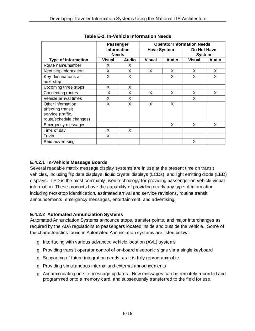
Developing Traveler Information Systems Using the National ITS Architecture
E-19
Table E-1. In-Vehicle Information Needs
Passenger Operator Information NeedsInformation
NeedsHave System Do Not Have
SystemType of Information Visual Audio Visual Audio Visual Audio
Route name/number X XNext stop information X X X X X XKey destinations atnext stop
X X X X X
Upcoming three stops X XConnecting routes X X X X X XVehicle arrival times X X XOther information affecting transitservice (traffic, route/schedule changes)
X X X X
Emergency messages X X XTime of day X XTrivia XPaid advertising X
E.4.2.1 In-Vehicle Message BoardsSeveral readable matrix message display systems are in use at the present time on transitvehicles, including flip data displays, liquid crystal displays (LCDs), and light emitting diode (LED)displays. LED is the most commonly used technology for providing passenger on-vehicle visualinformation. These products have the capability of providing nearly any type of information,including next-stop identification, estimated arrival and service revisions, routine transitannouncements, emergency messages, entertainment, and advertising.
E.4.2.2 Automated Annunciation SystemsAutomated Annunciation Systems announce stops, transfer points, and major interchanges asrequired by the ADA regulations to passengers located inside and outside the vehicle. Some ofthe characteristics found in Automated Annunciation systems are listed below:
g Interfacing with various advanced vehicle location (AVL) systems
g Providing transit operator control of on-board electronic signs via a single keyboard
g Supporting of future integration needs, as it is fully reprogrammable
g Providing simultaneous internal and external announcements
g Accommodating on-site message updates. New messages can be remotely recorded andprogrammed onto a memory card, and subsequently transferred to the field for use.

Developing Traveler Information Systems Using the National ITS Architecture
E-20
Beside this audio announcement, the locations are displayed inside the bus just above theoperator, for passengers with hearing disabilities. After the operator has stopped the bus andopened the door, visually impaired passengers outside the bus hear another automatedannouncement that identifies the bus route number and its destination. Hearing impairedcustomers can identify the bus route by the destination sign on the front of the bus.
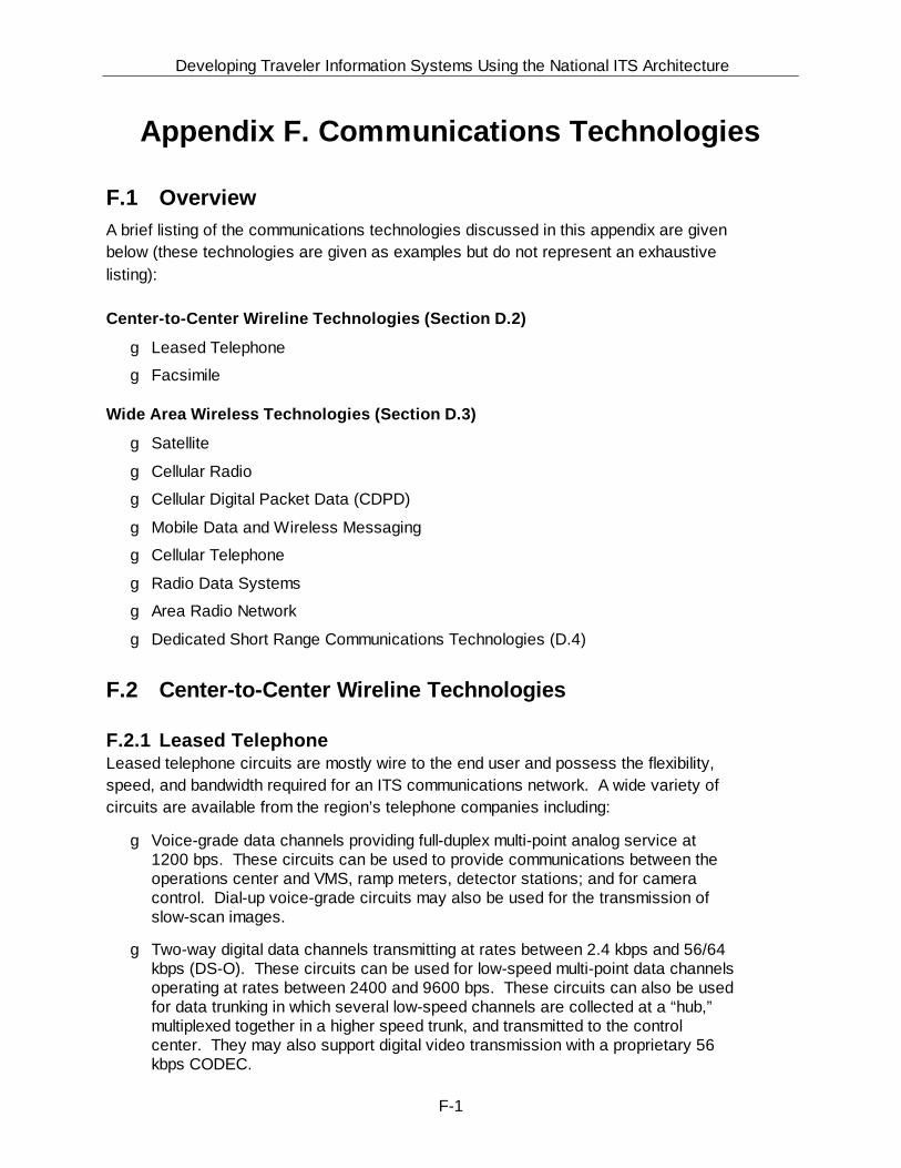
Developing Traveler Information Systems Using the National ITS Architecture
F-1
Appendix F. Communications Technologies
F.1 Overview A brief listing of the communications technologies discussed in this appendix are givenbelow (these technologies are given as examples but do not represent an exhaustivelisting):
Center-to-Center Wireline Technologies (Section D.2)
g Leased Telephone
g Facsimile
Wide Area Wireless Technologies (Section D.3)
g Satellite
g Cellular Radio
g Cellular Digital Packet Data (CDPD)
g Mobile Data and Wireless Messaging
g Cellular Telephone
g Radio Data Systems
g Area Radio Network
g Dedicated Short Range Communications Technologies (D.4)
F.2 Center-to-Center Wireline Technologies
F.2.1 Leased TelephoneLeased telephone circuits are mostly wire to the end user and possess the flexibility,speed, and bandwidth required for an ITS communications network. A wide variety ofcircuits are available from the region’s telephone companies including:
g Voice-grade data channels providing full-duplex multi-point analog service at1200 bps. These circuits can be used to provide communications between theoperations center and VMS, ramp meters, detector stations; and for cameracontrol. Dial-up voice-grade circuits may also be used for the transmission ofslow-scan images.
g Two-way digital data channels transmitting at rates between 2.4 kbps and 56/64kbps (DS-O). These circuits can be used for low-speed multi-point data channelsoperating at rates between 2400 and 9600 bps. These circuits can also be usedfor data trunking in which several low-speed channels are collected at a “hub,”multiplexed together in a higher speed trunk, and transmitted to the controlcenter. They may also support digital video transmission with a proprietary 56kbps CODEC.
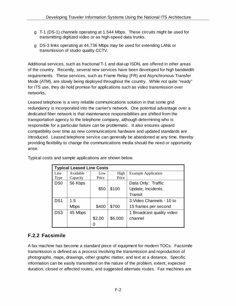
Developing Traveler Information Systems Using the National ITS Architecture
F-2
g T-1 (DS-1) channels operating at 1.544 Mbps. These circuits might be used fortransmitting digitized video or as high-speed data trunks.
g DS-3 links operating at 44,736 Mbps may be used for extending LANs ortransmission of studio quality CCTV.
Additional services, such as fractional T-1 and dial-up ISDN, are offered in other areasof the country. Recently, several new services have been developed for high bandwidthrequirements. These services, such as Frame Relay (FR) and Asynchronous TransferMode (ATM), are slowly being deployed throughout the country. While not quite “ready”for ITS use, they do hold promise for applications such as video transmission overnetworks.
Leased telephone is a very reliable communications solution in that some gridredundancy is incorporated into the carrier’s network. One potential advantage over adedicated fiber network is that maintenance responsibilities are shifted from thetransportation agency to the telephone company, although determining who isresponsible for a particular failure can be problematic. It also ensures upwardcompatibility over time as new communications hardware and updated standards areintroduced. Leased telephone service can generally be abandoned at any time, therebyproviding flexibility to change the communications media should the need or opportunityarise.
Typical costs and sample applications are shown below.
Typical Leased Line CostsLineType
AvailableCapacity
LowPrice
HighPrice
Example Application
DS0 56 Kbps $50
$100
Data Only: TrafficUpdate, Incidents,Transit
DS1 1.5Mbps
$400
$700
3 Video Channels - 10 to15 frames per second
DS3 45 Mbps$2,000
$6,000
1 Broadcast quality videochannel
F.2.2 Facsimile
A fax machine has become a standard piece of equipment for modern TOCs. Facsimiletransmission is defined as a process involving the transmission and reproduction ofphotographs, maps, drawings, other graphic matter, and text at a distance. Specificinformation can be easily transmitted on the nature of the problem, extent, expectedduration, closed or affected routes, and suggested alternate routes. Fax machines are

Developing Traveler Information Systems Using the National ITS Architecture
F-3
also capable of broadcasting faxes, i.e., one fax message can be sent to severalagencies.
In addition to fax machines, many E-mail software packages now have the capability ofaccepting data entry from various computers, storing the entered messages, andtransmitting these messages to fax machines. This allows for faxes to be sentautomatically to agencies.
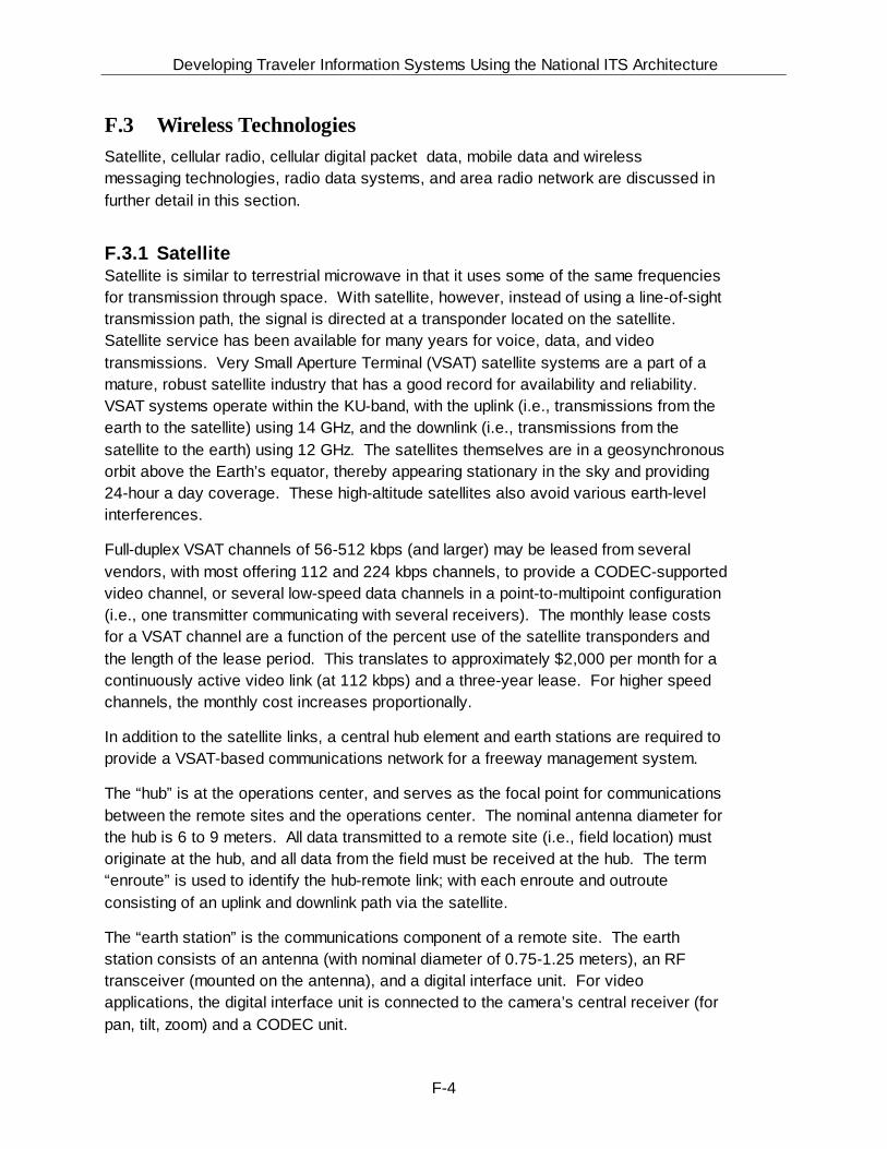
Developing Traveler Information Systems Using the National ITS Architecture
F-4
F.3 Wireless TechnologiesSatellite, cellular radio, cellular digital packet data, mobile data and wirelessmessaging technologies, radio data systems, and area radio network are discussed infurther detail in this section.
F.3.1 SatelliteSatellite is similar to terrestrial microwave in that it uses some of the same frequenciesfor transmission through space. With satellite, however, instead of using a line-of-sighttransmission path, the signal is directed at a transponder located on the satellite. Satellite service has been available for many years for voice, data, and videotransmissions. Very Small Aperture Terminal (VSAT) satellite systems are a part of amature, robust satellite industry that has a good record for availability and reliability. VSAT systems operate within the KU-band, with the uplink (i.e., transmissions from theearth to the satellite) using 14 GHz, and the downlink (i.e., transmissions from thesatellite to the earth) using 12 GHz. The satellites themselves are in a geosynchronousorbit above the Earth’s equator, thereby appearing stationary in the sky and providing24-hour a day coverage. These high-altitude satellites also avoid various earth-levelinterferences.
Full-duplex VSAT channels of 56-512 kbps (and larger) may be leased from severalvendors, with most offering 112 and 224 kbps channels, to provide a CODEC-supportedvideo channel, or several low-speed data channels in a point-to-multipoint configuration(i.e., one transmitter communicating with several receivers). The monthly lease costsfor a VSAT channel are a function of the percent use of the satellite transponders andthe length of the lease period. This translates to approximately $2,000 per month for acontinuously active video link (at 112 kbps) and a three-year lease. For higher speedchannels, the monthly cost increases proportionally.
In addition to the satellite links, a central hub element and earth stations are required toprovide a VSAT-based communications network for a freeway management system.
The “hub” is at the operations center, and serves as the focal point for communicationsbetween the remote sites and the operations center. The nominal antenna diameter forthe hub is 6 to 9 meters. All data transmitted to a remote site (i.e., field location) mustoriginate at the hub, and all data from the field must be received at the hub. The term“enroute” is used to identify the hub-remote link; with each enroute and outrouteconsisting of an uplink and downlink path via the satellite.
The “earth station” is the communications component of a remote site. The earthstation consists of an antenna (with nominal diameter of 0.75-1.25 meters), an RFtransceiver (mounted on the antenna), and a digital interface unit. For videoapplications, the digital interface unit is connected to the camera’s central receiver (forpan, tilt, zoom) and a CODEC unit.
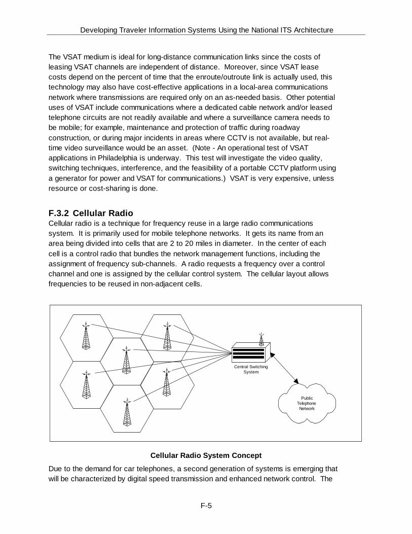
Developing Traveler Information Systems Using the National ITS Architecture
F-5
The VSAT medium is ideal for long-distance communication links since the costs ofleasing VSAT channels are independent of distance. Moreover, since VSAT leasecosts depend on the percent of time that the enroute/outroute link is actually used, thistechnology may also have cost-effective applications in a local-area communicationsnetwork where transmissions are required only on an as-needed basis. Other potentialuses of VSAT include communications where a dedicated cable network and/or leasedtelephone circuits are not readily available and where a surveillance camera needs tobe mobile; for example, maintenance and protection of traffic during roadwayconstruction, or during major incidents in areas where CCTV is not available, but real-time video surveillance would be an asset. (Note - An operational test of VSATapplications in Philadelphia is underway. This test will investigate the video quality,switching techniques, interference, and the feasibility of a portable CCTV platform usinga generator for power and VSAT for communications.) VSAT is very expensive, unlessresource or cost-sharing is done.
F.3.2 Cellular RadioCellular radio is a technique for frequency reuse in a large radio communicationssystem. It is primarily used for mobile telephone networks. It gets its name from anarea being divided into cells that are 2 to 20 miles in diameter. In the center of eachcell is a control radio that bundles the network management functions, including theassignment of frequency sub-channels. A radio requests a frequency over a controlchannel and one is assigned by the cellular control system. The cellular layout allowsfrequencies to be reused in non-adjacent cells.
PublicTelephoneNetwork
Central SwitchingSystem
Cellular Radio System Concept
Due to the demand for car telephones, a second generation of systems is emerging thatwill be characterized by digital speed transmission and enhanced network control. The
Developing Traveler Information Systems Using the National ITS Architecture
F-6
new system will provide greater bandwidth and frequency reuse capability. In NorthAmerica, standard IS-54 has been written to govern digital cellular. This standardspecifies that a time-division multiple access (TDMA) scheme be used to split thebandwidth of each of the existing cellular channels into three channels. Each channelwould then carry compressed digitized voice. Though the initial standard did notaddress data transmission, the latest revision does.
Recent advances in an alternate technology, code division multiple access (CDMA),have stalled the acceptance of IS-54 and the changeover to digital cellular. CDMA is aspread-spectrum technique distributing the signal over a range of frequencies. Thegoverning standard for cellular systems using CDMA is IS-95. In the interim, analternate technology, cellular digital packet data (CDPD), that permits the transmissionof data over the existing cellular network, is being introduced by McCaw, IBM, andseveral other companies. In CDPD, data is formed into packets which are transmittedat a data rate of 19.2 kb/s over idle voice channels. CDPD is being tried in Las Vegasand is scheduled for nationwide testing.
With the new networks likely having the same or similar rate structure, cellular radiowould be economically unsuitable for constant connections with fixed (as opposed tomobile) devices such as ramp meters and detectors. On the other hand, devices suchas VMS and HAR, where communications are needed only on an as-needed basis, maybe suited to cellular radio.
Cellular radio service was introduced to the United States in 1983 and currently hasgrown to over 16 million subscribers. The United States is divided into 734 serviceareas by the FCC with each service area being divided into cells serviced by a low-powered radio transceiver. The transceiver is connected to a Mobile Switching Center(MSC) which is in turn connected to the Public Switched Telephone Network. Inmoving from one cell's coverage area to another, the MSC tracks the call andautomatically "hands off" the call to the other cell site. While the "hand off" is barelynoticeable for voice communication, it can seriously degrade data communication;hence the reason that cellular calls were primarily intended to serve voicecommunication. However, new digital cellular-phones can serve as a data-communications system if a modem is connected between the cellular telephone and acomputer. Cellular radio communications offers many advantages for traffic control. Itis readily accessible since it is estimated that about 93 percent of the United States iscovered by cellular service. Although cellular service can be expensive depending onthe usage, from $0.19/minute (off-peak) to $0.55/minute (peak), it can prove to be costeffective where infrequent communication is required by eliminating the need to provideowned land lines. It can also prove effective for temporary installation and in controllingportable VMS and HAR devices. Cellular telephone service can be used to transmitdata between agencies and can provide an effective alternative to fixed point-to-pointcommunications for traffic control purposes, e.g., reporting on the status of alternateroutes during incidents.
Developing Traveler Information Systems Using the National ITS Architecture
F-7
F.3.3 Cellular Digital Packet Data (CDPD)The newest of the cellular technologies is Cellular Digital Packet Data (CDPD). Thistechnology is a digital data connection provided over existing cellular telephonenetworks. The most important feature of this technology is its relative low cost for basicconnectivity. By using the voice infrastructure for digital pathways in such a way as tointerfere very little with the voice functionality, this technology allows almost universalcoverage with little investment in new infrastructure. The cost effectiveness is high forcommunication solutions which require random intermittent connectivity and shortmessage length.
The growing demand by cellular telephone customers who want to be able to transmitdata over the cellular telephone network has driven the creation of CDPD standards. This packet data technology has had an overwhelming response from cellular carriers inthe United States. CDPD is an open industry standard making it available to anydeveloper for virtually any wireless data packet transmission application. CDPDsystems will provide high system throughput, accommodate multiple host connections,have the capability to store data messages, allow electronic data interchange, accesspublic databases, support interactive sessions with electronic mail system servers, andperform file transfers. Although CDPD uses the circuit switched cellular telephonenetwork as its transport medium, CDPD is a packet switched architecture.
CDPD will allow the cellular telephone user to utilize a single wireless service for bothvoice and data requirements. This will make CDPD one of the fastest growingtechnology applications of the 1990's.
F.3.4 Mobile Data and Wireless MessagingPrivate wireless mobile data services have been in use by several large corporations inthe United States since the early 1980's. Public wireless mobile data and messagingcommunication services have been in varying degrees of use in the United States andsome European and Asian countries for several years. These systems/services haveprimarily been used to support field service organizations, fleet vehicle management,and some emergency services. The last two years have seen enormous growth in theuse of these networks for Personal Communication Systems (PCS), primarily in theareas of electronic mail and remote log-in to host based applications.
As is the case with any wireless service their availability and reliability have directcorrelation to the radio frequency (RF) "cloud" and the protocols utilized. These servicecapabilities are provided by wireless networks whose sole function is to support thetransmission of packetized data. To the network there is no difference between thedifferent types of data or end-user application(s) with which they communicate. Theyare simply data packets and as such are transmitted and routed in virtually the samemanner as any other packet network. In the U.S., experience to date has shown thatthe most successful mobile data wireless messaging and mobile radio applications
Developing Traveler Information Systems Using the National ITS Architecture
F-8
have used packet switching as the transmission technology and architecture of choice. Almost all of these networks have chosen the CCITT Standard X.25 as their protocol ofchoice. Data throughput in these networks has a direct correlation to the frequencybandwidth allowed for the specific frequency band as set by the ITU/IRAC and/or thegoverning frequency control and management entity of the host country.
F.3.5 Radio Data SystemsThe Radio Data System (RDS), which is covered by the United States Radio BroadcastData System (RBDS) Standard, was developed for Frequency Modulation (FM) by theEuropean Broadcasting Union (EBU) and its member countries. It is a form of datacoding channel designed to operate in conjunction with commercial FM radiobroadcasts.
The Exhibit below illustrates the RDS principle. Commercial FM radio has “space”between the frequencies. This spare space, which serves as a buffer between stations,can be used to convey a subsidiary audio program or to transmit digital information.This subcarrier has been used in the past to play background music (i.e., MUZAK) inrestaurants and shops. The effectiveness of the system lies in the fact that there is nocrosstalk from the subcarrier into the main audio program.
The primary motivation behind RDS is to allow commercial radio broadcasters to beidentified on the radio’s front panel, and to allow special self-turning radios toautomatically select the strongest signal carrying a particular type of program (e.g.,news, sports, drama, different types of music, and traffic). From an ITS perspective, animportant feature of RDS is the Traffic Message Channel (TMC) that can providemotorists with the latest traffic information by superimposing inaudible data on existingFM station carriers. The TMC is an additional feature of RBDS that is aimed atproviding a better method for transmitting information. The traffic informationtransmitted to motorists via the RDS digitally encoded silent messages will trigger adisplay and/or speech synthesizer in the in-vehicle receiver. The messages arelanguage-independent; they can be decoded into the language of the user’s choice. Incoming messages are stored in receiver memory and can be selected by the useraccording to travel corridor, area, or highway route numbers.
RDS-TMC requires a special decoder. This is because RDS-TMC is a subcarrier thatconsists of ultrasonic signals above the range of human hearing. Moreover,conventional radios cannot decode these signals without the added special decoder. The basic implementation allows a radio to indicate whether or not the tuned stationbroadcasts traffic information as part of its programming, and whether the tuned stationis currently broadcasting a traffic message. This information could be used to stop acassette or CD and turn on the radio for the duration of the announcement. RDS radiostypically allow the listener to use this information as a search criteria when scanning theband, stopping only on stations which broadcast traffic information. While thereceiver/decoder generally provides the user interface to the traveler information

Developing Traveler Information Systems Using the National ITS Architecture
F-9
service, its functionality may vary substantially according to technical developments andmarket requirements.
RDS Principle
The RDS-TMC has the capability of transmitting information using “virtual language.” Under this specification, the codes broadcast over-air comprise addresses ofinformation stored in databases in the decoders. These databases contain look-uptables for coded values of different variables, plus lists of locations, including road ortransit links. The processes involved in applications using this specification are asfollows:
Developing Traveler Information Systems Using the National ITS Architecture
F-10
g Before transmission, information is mapped into the virtual language by selectionfrom look-up tables and location tables.
g The resulting coded messages are transmitted via RBDS, with frequentrepetitions.
g In the receiver, codes received are translated back into user information usinglook-up tables, for use by the route guidance system or for presentation to thetraveler.
F.3.6 Area Radio NetworkArea Radio Networks (ARN) refer to systems that broadcast signals to an area ratherthan to a specific location. These are also known as Specialized Mobile Radio (SMR) orPrivate Land Mobile Radio Services (PLMRS). ARNs are primarily utilized in thedispatch of bus and taxi fleets.
Area radio signals radiate uniformly in all directions, unlike point-to-point microwavelinks. As the signal multiplies it may 'bend' slightly over changes in the ground surface,reflect off buildings or other obstacles, and penetrate into buildings. Scattering andreflection allow the signal to extend into built-up areas although these effects reducesignal strength. Terrain barriers may limit the feasibility of this technology.
There are various frequency bands available for ARN applications. Typically, onefrequency pair is allocated for an application, meaning that all the applicationtransmitters must share the transmit and receive channels. Thus, for voicecommunications, all receivers tune to the same broadcast and users respond only tomessages directed to them.
A more sophisticated version of this technology is known as Enhanced SpecializedMobile Radio (ESMR). This radio utilizes digital technology to enable more users perchannel and provide more services to the user. ESMR is provided by companies suchas Nextel, Dial Page and Cencall, who own licenses for use of SMR frequencies acrossthe USA. Services based on this technology are likely to represent major competitionfor cellular telephone services in the near future.
F.4 Dedicated Short Range Communications (DSRC)Also known as vehicle-roadside communications (VRC), DSRC consists of short-rangecommunications devices that are capable of transferring high rates of data over an airinterface between mobile or stationary vehicles and normally stationary devices that aremounted to structures along the roadway or are hand-held. One way of accomplishingthis communications is through use of Radio Frequency (RF) beacons. RF beacontechnology generally consists of a transponder (tag), transceiver (reader) andtransceiver antenna (beacon).
Developing Traveler Information Systems Using the National ITS Architecture
F-11
To support deployment of nationally, and perhaps internationally, compatible IntelligentTransportation Systems (ITS) using DSRC, the ITS Joint Program Office (JPO) in theU.S. Department of Transportation issued a work order to build consensus andgenerate the necessary documentation to support the process for developing adedicated short range communications standard for ITS applications, both for the nearterm and for the long term.
Developing Traveler Information Systems Using the National ITS Architecture
F-12
A movement is underway that describes consensus among the user and vendorcommunities as to the operation of all ITS applications that require use of RF beaconDSRC. This is based on the state of the practice, and activities underway to supportintegration of different applications and technologies, so that a single tag could be usedfor multiple applications, or tags from multiple vendors could be used for the sameapplication.
Establishment of consensus standards requires “buy-in” from both of these groups. Another important audience is all others involved in the process of trying to establishnational ITS standards, including USDOT personnel, ITS AMERICA members,American Society of Testing Materials (ASTM), and Institute of Electrical and ElectronicEngineers (IEEE) members, and representatives of other involved and affectedstandards developing organizations.
The National ITS Architecture recognizes the need for DSRC for those specificapplications that require a close physical interaction between the vehicle and theroadside infrastructure, such as in toll collection, commercial vehicle electronicclearance and roadside safety inspection, etc.
In electronic toll collection, data is transferred from and to the vehicle’s tag, while thevehicle is in a toll area, and the fee is automatically deducted from the driver’s tollaccount or other monetary account. Beacon technology is used so that the tollcollection agency can positively identify the location of the vehicle, both at the time ofthe toll transaction and when the vehicle enters the toll road, ensuring that the driver isbilled correctly. This application allows the toll agency to reduce the cost of tollcollection and allows the driver to proceed through the toll area without slowing,stopping, or experiencing traffic backups.
Using the parking payments application, a vehicle enters and exits a parking area, andthe parking fee is automatically deducted from the driver’s parking account or othermonetary account. Beacon technology is used so that the parking agency can positivelyidentify the location of the vehicle both at the time of the payment transaction and whenthe vehicle enters the parking area, ensuring that the driver is correctly billed. Thisapplication allows the parking agency to reduce the cost of parking payment collectionand allows the driver to enter and leave the parking area faster.
Commercial Vehicle Operations (CVO) services require DSRC systems to provide two-way real-time communication between appropriately equipped commercial vehicles andthe roadside infrastructure. There are a number of CVO services for which DSRCsystems are incorporated to provide the service. International Border Clearance is theprocess of electronically transferring data between a commercial vehicle and the bordercheckpoint so that the vehicle can pass the checkpoint with minimal or no delay.Electronic Clearance is the process of electronically transferring data betweencommercial vehicle and the roadside checkpoint so that the vehicle can pass thecheckpoint without stopping. This process obtains important vehicle informationincluding weight, credentials, and safety information. Safety Inspection is a check of
Developing Traveler Information Systems Using the National ITS Architecture
F-13
the safety characteristics of a commercial vehicle while it has been pulled off thehighway at a fixed or mobile inspection site. Beacon technology is used to speed theinspection process since it does not require physical contact with the vehicle and it cantransfer registration data, previous inspection data, and on-board sensor data at hightransfer rates. Automatic Equipment Identification and Freight Management enablesintermodal freight management to accommodate the need to track freight as ittransitions from one mode of transportation to another. Off-Line Verification is a checkof the data in a tag’s memory when a vehicle has been stopped for any reason by anenforcement agency. Beacon technology is used to provide a fast, common interfacefor data. Power unit and electronic tags can transmit data to a hand-held reader carriedby an enforcement agent.
DSRC technology can be used to allow for transit signal priority, transit vehicle datatransfer and emergency vehicle signal preemption. Transit vehicle signal priority usesbeacon technology in both an intersection and a transit vehicle to change the timing ofa traffic signal and allow the vehicle to proceed through the traffic signal with aminimum of delay. Transit vehicle data transfer is the uplink of operational data fromand the downlink of messages to an individual transit vehicle or a fleet of transitvehicles, using beacon technology. Beacons are positioned at transit vehicle stopsalong a route, and communications are initiated with tag-equipped vehicles at the stopsas necessary. Emergency vehicle signal preemption uses beacon technology in bothan intersection and emergency vehicle to change the timing of a traffic signal and allowthe emergency vehicle to proceed through the intersection with a green light and aminimum of delay.