wps/916/02 waste package guidance documentation: guidance
TRANSCRIPT

Waste Package Guidance Documentation: Guidance on Demonstrating Criticality Safety for Fissile Waste Packages March 2020
WPS/916/02

Radioactive Waste Management i
Conditions of publication
This report is made available under the Radioactive Waste Management Limited (RWM) Transparency Policy. In line with this policy, RWM is seeking to make information on its activities readily available, and to enable interested parties to have access to and influence on its future programmes. The report may be freely used for non-commercial purposes. RWM is a wholly owned subsidiary of the Nuclear Decommissioning Authority (NDA), accordingly all commercial uses, including copying and re publication, require permission from the NDA. All copyright, database rights and other intellectual property rights reside with the NDA.
Applications for permission to use the report commercially should be made to the NDA Information Manager.
Although great care has been taken to ensure the accuracy and completeness of the information contained in this publication, the NDA cannot assume any responsibility for consequences that may arise from its use by other parties.
© Nuclear Decommissioning Authority 2020 All rights reserved.
Other publications
If you would like to see other reports available from RWM and the NDA, a complete listing can be viewed at our website www.nda.gov.uk, or please write to us at the address below.
Feedback
Readers are invited to provide feedback on this report and on the means of improving the range of reports published. Feedback should be addressed to:
RWM Feedback Radioactive Waste Management Building 329 Thomson Avenue Harwell Campus Didcot OX11 0GD
email: [email protected]
Conditions of publication

Radioactive Waste Management ii
This document forms part of the Waste Package Specification and Guidance Documentation (WPSGD) suite, which is intended to assist waste packagers in the development of plans for the packaging of higher activity waste in a manner suitable for geological disposal. The WPSGD is subject to periodic enhancement and revision. Therefore, users are advised to contact RWM or refer to the RWM website (www.gov.uk/guidance/generic-waste-package-specification) to ensure that they are in possession of the latest version of any documentation used.
Executive Summary
Radioactive Waste Management Ltd (RWM) has established the Disposability Assessment Process to support waste producers in the development of plans to package higher activity wastes. A waste package is deemed by RWM to be disposable if it can be shown to be compliant with the packaging criteria specified in the relevant Waste Package Specification (WPS) and with the assumptions made in the safety cases for transport to and disposal in a geological disposal facility (GDF). As part of the Waste Package Specification and Guidance Documentation (WPSGD) suite that supports the Disposability Assessment Process, this document provides guidance for waste packagers on how criticality safety can be ensured and demonstrated for proposed waste packages from the point of export to the GDF.
The process to be followed and the options available for demonstrating the criticality safety of low heat generating waste (LHGW) disposal are summarised in Table ES-1, with references provided to relevant sections of the guidance. It is recommended that waste packagers seek any further guidance that they may require from RWM on options for demonstrating the criticality safety of proposed waste packages at the earliest opportunity.
Conditions of publication
Version Date Comments
WPS/916/01 November 2013
Aligns with Generic Specification for waste packages containing low heat generating waste (NDA/RWMD/068) as published August 2012.
Based on 2007 and 2013 work by Galson Sciences Ltd for GDF operational and post-closure periods and 1998 RSTC PDSR for transport.
WPS/916/02 December 2019
Significant revision to improve clarity and to include recent advances allowing waste producers and RWM to demonstrate post-closure criticality safety using probabilistic analysis. Report title revised to reflect that criticality safety relies on more than just limiting the fissile mass in waste packages. Guidance on CCAD preparation (previously WPS/625) merged into this document to support consistency in the demonstration and assurance of criticality safety.
WPSGD Document number WPS/916 - version history

Radioactive Waste Management iii
Conditions of publication
CSA options and approach (Guidance Part 1)
Waste package assessment (§4.1)
Transport phase(§3.2)
Operational phase (§3.3)
Post-closure phase (§3.4)
Fissile material masses and/or concentrations are small
Show that the transport package contains non-fissile or fissile excepted material (§3.2.1)
Provide high-level arguments that criticality is not credible during disposal operations (§4)
Provide high-level arguments that criticality is not credible after disposal (§4)
The General CSA (GCSA) criteria are satisfied
Show that the transport package contains non-fissile or fissile excepted material (§3.2.1) or apply the results of the Reusable Shielded Transport Container (RSTC) assessment (§4.3)
Apply the General Screening Level (GSL) (§4.12)
Apply the GSL (§4.12)
The criteria of one of the generic CSAs (gCSAs) are satisfied
Apply the results of the RSTC assessment (§4.3)
Apply the appropriate Lower or Upper Screening Level (LSL or USL) (§4.3)
Apply the appropriate LSL or USL (§4.3)
The post-closure package envelope criteria are satisfied
Apply the results of the RSTC assessment (§4.3) or produce a package-specific CSA (§3.2, §4.6)
Apply an applicable LSL or USL (§4.3) or produce a package-specific CSA (§3.3 and 4.6)
Apply the package envelope limits (§4.4)
The package does not satisfy criteria associated with the GCSA, a gCSA or the post-closure package envelope
Produce a package-specific CSA (§3.2, §4.6, §5.1)
Extend a gCSA or produce a package-specific CSA (§3.3, §4.5, §4.6, §5.1)
Extend a gCSA or the package envelope (§3.4, §4.5) or produce a package-specific CSA (§3.4, §4.6, §5.1)
CSA scope and methodology (Guidance Part 1)
The CSA for the proposed waste package must provide criticality safety constraints that ensure criticality safety requirements are met for the waste package transport and GDF operational and post-closure phases based on consideration of RWM’s illustrative disposal concept designs (§2, §3.1)
CCAD (Guidance Part 2)
Produce CCAD that describes how waste packages will be produced in a way that is proportionate (§7) and ensures demonstrable compliance with the criticality constraints defined in the CSA (§8)
Table ES-1: Criticality Safety Assessment (CSA) options and Criticality Compliance Assurance Documentation (CCAD) for LHGW packages

iv
List of Contents
Conditions of Publication iExecutive Summary iiInitialisms and acronyms used in this document v
1. Introduction 11.2 Criticality safety demonstration 11.3 Objective and scope 21.4 Audience and users 31.5 Document structure 3
Part 1 – Preparation of a Criticality Safety Assessment 4
2. The Basis of a Criticality Safety Assessment 52.1 Background 52.2 CSA requirements 6
3. Criticality Safety Assessment Methodology 83.1 Criticality safety assessment methodology summary 93.2 Criticality safety assessment for transport to the GDF 113.3 GDF operational phase criticality safety assessment 153.4 GDF post-closure phase criticality safety assessment 173.5 Derivation of waste package criticality controls 21
4. Options for Production of a CSA for LHGW Packages 224.1 The hierarchy of criticality safety assessments for LHGW packages 234.2 Scope and Limits of the General CSA 274.3 Scope and Limits of the Generic CSAs 314.4 Post-closure package envelope approach 584.5 Extension of the gCSA or package envelope approach 624.6 Development of a package-specific CSA 624.7 Revision of the waste packaging concept 654.8 Consideration of arguments relating to the low consequence of criticality 65
5. Criticality Safety Approach for HHGW Packages 665.1 Potential Criticality Safety Constraints and Controls 66
Part 2 – Preparation of Criticality Compliance Assurance Documentation 68
6. The Basis for Criticality Compliance Assurance Documentation 696.1 Background 696.2 CCAD Requirements 69
7. Proportional Approach to Preparing Criticality Compliance Assurance Documentation 71
8. Content of Criticality Compliance Assurance Documentation 748.1 Identify Criticality Safety Constraints 758.2 Describe Arrangements for Criticality Compliance Assurance 768.3 Define Waste Package Data to be Recorded 78
References 79
Appendix A – Glossary 82
Appendix B – General Principles and Requirements for Criticality Safety 84
List of Contents Radioactive Waste Management

v
Initialisms and acronyms used in this document
ALARP As Low As Reasonably Practicable
BAT Best Available Technique
CCAD Criticality Control Assurance Documentation
CSA Criticality Safety Assessment
CSSR Criticality Safety Status Report
DAAPs Disposability Assessment Aim and Principles
DCTC Disposal Container Transport Container
DNLEU Depleted, Natural and Low-Enriched Uranium
DSS Disposal System Specification
DSSC Disposal System Safety Case
EA Environment Agency
FED Fuel Element Debris
FEPs Features, Events and Processes
GCSA General Criticality Safety Assessment
gCSA generic Criticality Safety Assessment
GDF Geological Disposal Facility
GRA Guidance on Requirements for Authorisation
GSL General Screening Level
HEU High-Enriched Uranium
HHGW High Heat Generating Waste
HLW High Level Waste
HSR Higher Strength Rock
IAEA International Atomic Energy Agency
ILW Intermediate Level Waste
INU Irradiated Natural Uranium
LEU Low-enriched Uranium
LHGW Low Heat Generating Waste
LLW Low Level Waste
Initialisms and acronyms used in this document Radioactive Waste Management

vi
Initialisms and acronyms used in this document
LoC Letter of Compliance
LSL Lower Screening Level
LSSR Lower Strength Sedimentary Rock
LTCSA Long-term CSA
MOX Mixed Oxide fuel
MPC Multi-Purpose Containers
NDA Nuclear Decommissioning Authority
NIEA Northern Ireland Environment Agency
NRW Natural Resources Wales
NSSEC Nuclear Safety Security and Environment Committee
ONR Office for Nuclear Regulation
PCM Plutonium Contaminated Material
PDSR Package Design Safety Report
PWR Pressurised Waste Reactor
RSC Robust Shielded Container
RSTC Reusable Shielded Transport Container
RWM Radioactive Waste Management Ltd
SAPs Safety Assessment Principles
SEPA Scottish Environment Protection Agency
SFM Safe Fissile Mass
SQEP Suitably Qualified and Experienced Person
STCSA Short-term CSA
SWTC Standard Waste Transport Container
TCSC Transport Container Standardisation Committee
USL Upper Screening Level
WPS Waste Package Specification
WPrS Waste Product Specification
WPSGD Waste Package Specification and Guidance Documentation
Initialisms and acronyms used in this document Radioactive Waste Management

1. Introduction1
1. Introduction
1.1 Radioactive Waste Management Ltd (RWM) has established the Disposability Assessment Process [ ] to support waste producers in the development of plans to package higher activity wastes. Specifically, RWM uses the Disposability Assessment Process to judge whether the implementation of proposals to package a specific waste stream in a given manner would result in ‘disposable’ waste packages [ 2, §5.1]. A waste package is deemed by RWM to be disposable if it can be shown to be compliant with the packaging criteria specified in the relevant Waste Package Specification (WPS) and with the assumptions made in the safety cases for transport to and disposal in a geological disposal facility (GDF). As part of the Waste Package Specification and Guidance Documentation (WPSGD) suite that supports the Disposability Assessment Process, this document provides guidance for waste packagers on how criticality safety must be ensured and demonstrated for proposed waste packages from the point of export to the GDF.
1.2 Criticality safety demonstration1.2 A criticality safety demonstration for the transport and disposal of proposed waste
packages comprises two components:
— a criticality safety assessment (CSA), which derives the constraints on waste packaging that will ensure that criticality safety requirements for waste package transport and disposal are met; and
— Criticality Compliance Assurance Documentation (CCAD) that describes the arrangements that will be in place during waste package manufacture to ensure that the criticality safety constraints derived in the waste package CSA will be met, and the records to be provided as evidence that a waste package complies with the criticality safety constraints.
The waste package CSA and CCAD will form the basis of arguments and evidence to support RWM’s future criticality safety case for the GDF. These documents and associated packaging records will be required at the time of waste consignment to demonstrate that the waste package meets the waste acceptance criteria for the GDF.
Radioactive Waste Management

2
1.3 Objective and scope1.3 The objectives of this document are to:
— explain and provide guidance on how a waste packager may identify or derive criticality safety constraints through application or development of a CSA in support of packaging proposals to RWM for waste destined for geological disposal; and
— provide guidance on the information (CCAD) required from waste packagers to demonstrate that sufficiently robust waste packaging procedures and process controls will be in place to ensure that criticality safety constraints derived in the CSA will be complied with.
1.4 This guidance focuses primarily on criticality constraints for low heat generating waste (LHGW) packages because RWM’s approach to developing criticality safety constraints for high heat generating (HHGW) packages1 is at a less advanced stage than for LHGW packages.
1.5 This guidance does not cover every eventuality in terms of waste packages that may be produced. Waste packagers are strongly encouraged to speak to RWM at an early stage of waste package concept development in order to identify the optimal approach to ensuring criticality safety and how this may be balanced against other risks.
1.6 To constrain the scope of this document, the wider Disposability Assessment Process and its requirements, the regulatory framework and RWM’s research on criticality safety are described only briefly in Appendix B. References to further information are provided as appropriate throughout this document, but readers are referred in particular to the following documents:
— the overview of the generic Disposal System Safety Case (DSSC) [3] and the DSSC’s three main safety case reports covering transport [4], operational [5] and post-closure environmental safety [6];
— the status of RWM’s research on and approach to criticality safety in the GDF summarised in the Criticality Safety Status Report (CSSR) [7];
— an overview of the Disposability Assessment Process provided in WPS/650 [1];
— guidance on preparation of waste packaging submissions to RWM in WPS/908 [8];
— guidance provided in WPS/911 [9] that focuses on application of the fissile exception criteria of the International Atomic Energy Agency (IAEA) Regulations for the Safe Transport of Radioactive Material (the ‘IAEA Transport Regulations’) [10]; and
— guidance on waste package data and information recording requirements provided in WPS/850 [11].
1. Introduction Radioactive Waste Management
1 HHGW includes high-level waste (HLW), spent fuel, separated plutonium and high-enriched uranium (HEU). LHGW includes low-level waste (LLW) destined for disposal in the GDF, intermediate-level waste (ILW) and depleted, natural and low-enriched uranium (DNLEU).

3
1.4 Audience and users1.7 The primary external audience for this guidance document is the waste packagers; that
is, those responsible for the conditioning and packaging of waste containing fissile material for eventual disposal in the GDF. The primary internal user of the guidance document is RWM’s disposability assessment team, including its contractors.
1.8 The guidance is written for an audience with a scientific or technical background and with some knowledge of the context of geological disposal and nuclear criticality, but it does not assume that readers are criticality safety professionals. However, it is assumed that sufficiently qualified and experienced personnel will develop and assess the waste package criticality safety demonstration.
1.5 Document structure1.9 The guidance is presented in two parts, with Part 1 providing guidance on the
preparation of CSAs and Part 2 providing guidance on the preparation of CCAD. Part 1 is structured as follows:
— Section 2 discusses the basis and requirements for waste package CSAs;
— Section 3 summarises issues that need to be considered in any CSA for waste packages destined for geological disposal, covering transport to the GDF and the GDF operational and post-closure phases;
— Section 4 presents the range of CSA options available to waste packagers for identifying or deriving criticality safety constraints for LHGW packages; and
— Section 5 discusses the criticality safety constraints that may be applied to HHGW packages.
1.10 Part 2 comprises the following sections:
— Section 6 discusses the basis and requirements for waste package CCAD;
— Section 7 describes a proportionate approach to preparing CCAD; and
— Section 8 provides guidance on the contents of the CCAD.
1.11 Appendix A provides a glossary and Appendix B provides background information to support users of this guidance, which includes an introduction to the nature of the criticality hazard, definitions of criticality safety and criticality controls, and summaries of the regulatory framework, RWM’s waste package specification and requirements documentation, and the Disposability Assessment Process, focusing on criticality safety.
1. Introduction Radioactive Waste Management

4Part 1 – Preparation of a Criticality Safety Assessment Radioactive Waste Management
Part 1
Preparation of a Criticality Safety Assessment

2. The Basis of a Criticality Safety Assessment5
2. The Basis of a Criticality Safety Assessment
2.1 Background2.1 Implementation of a GDF for higher activity wastes requires RWM to demonstrate that
such a facility would meet safety standards during both the operational period and after the facility has been sealed and closed. As part of that process, RWM has developed the generic DSSC [3], the prime purpose of which is to demonstrate that a GDF can be implemented in a safe manner and in such a way that would meet all regulatory requirements. The regulatory requirements that RWM must meet are different for each of the three GDF waste management phases: transport of waste to the facility; activities during operation of the facility; and long-term post-closure safety once the facility is closed. As such, the DSSC comprises three safety case reports, each assessing one of the three waste management phases [4, 5, 6]. The generic DSSC also forms a benchmark against which RWM provides advice to waste producers on the packaging of wastes for disposal [2, §1.1].
2.2 RWM will need to submit a facility-specific safety case to the regulators in order to construct the GDF and be licensed to receive waste once the final GDF design, location and expected content are known. Although this will not be possible for a number of years, waste packages have been and are continuing to be produced. The information captured through the Disposability Assessment Process forms part of the knowledge base for the eventual safety case to be produced by RWM.
2.3 Some wastes include fissile radionuclides (predominantly U-235 and Pu-239) and the development of waste packaging solutions for such wastes must address criticality safety requirements associated with each phase of waste management. That is, waste packages must be consistent with requirements that [12] ‘[t]he presence of fissile material, neutron moderators and reflectors in the waste package shall be controlled to ensure that:
— criticality during transport is prevented
— the risk of criticality during the GDF operational period is tolerable and as low as reasonably practicable
— in the GDF post-closure period both the likelihood and consequences of criticality are low.’
Radioactive Waste Management

2.4 These criticality safety requirements are met by controlling how the wastes are packaged as well as controlling the waste package transport and disposal processes. Criticality safety constraints on waste packaging typically involve limiting the fissile material content of the waste package, but they may also include requirements on the arrangement or distribution of fissile material in the waste package and constraints on the presence of neutron moderating, absorbing and reflecting materials, as well as requirements on the type and properties of the container.
2.5 By establishing suitable constraints on the packaging of fissile wastes through use or production of a CSA, RWM will be able to demonstrate criticality safety through each phase of waste management. Such criticality safety demonstrations will form components of the disposal system safety cases to be submitted to the regulators at specific stages of the GDF development process in order to demonstrate that a geological disposal system can be implemented safely. These disposal system safety cases and the claims they make will be based on safety arguments that will become progressively refined as understanding of the disposal system increases and the underpinning evidence base is enhanced.
2.6 Accordingly, criticality safety claims will need to be supported by safety arguments (the subject of this part of the guidance) and a suitable evidence base in the form of assurances that wastes can and will be packaged as proposed (the subject of Part 2 of the guidance), as well as appropriate records for wastes that have been packaged.
2.2 CSA requirements2.7 RWM’s WPSGD provides the requirements against which the suitability of plans to
package radioactive waste for geological disposal can be assessed (see Section B4). In particular:
— Part C sets out Fundamental Requirements on the packaging of low heat generating wastes such that they are suitable for transport and disposal [13].
— Part D provides Container-specific Requirements for a standard range of containers used to package low heat generating waste [14].
2.8 The requirements specific to a waste package CSA that will need to be met by the information presented in the waste packaging proposal are as follows:
C131 A safe fissile mass (SFM) for the waste package shall be derived and presented in Criticality Safety Assessments for the Transport, Operational and Post Closure phases of a GDF.
C132 The most restrictive safe fissile mass derived from the three phases shall set the package fissile material limit.
62. The Basis of a Criticality Safety Assessment Radioactive Waste Management

The following requirement is derived from the IAEA transport Regulations paragraphs 222, 417 and 674, and 673 respectively:
C133 A criticality safety demonstration shall be made for waste package transport that satisfies the IAEA Transport Regulations in one of the following ways [10]:
a) A non-fissile case shall be made under Para 222.
b) A fissile exception case shall be made under Para 417, or Para 674.
c) For fissile waste material a criticality safety case shall be provided according to Para 673.
C134 The General Criticality Safety Assessment (GCSA) or generic Criticality Safety Assessments (gCSA) should be used to derive the SFM of the proposed waste package.
C135 If a GCSA or gCSA cannot be used directly or modified, a package specific CSA shall be developed in order to derive a safe fissile mass and the associated constraints.
2.9 It is recognised that criticality safety requirements associated with waste packaging and storage may provide a more restrictive safe fissile mass (SFM) than derived in the transport and GDF operational and post-closure phase assessments. Also, note that application of a SFM typically requires compliance with other waste packaging constraints, such as on the container type, the distribution of fissile material in the waste package and on other materials present.
72. The Basis of a Criticality Safety Assessment Radioactive Waste Management

8
3. Criticality Safety Assessment Methodology
3.1 The objective of a waste package CSA is to determine the waste packaging constraints that will ensure compliance with the criticality safety requirements associated with all phases of radioactive waste management, from conditioning, packaging and interim storage through to transport to, and disposal in, the GDF. Adherence to this principle helps to ensure that repackaging at different waste management stages is avoided, and builds confidence that waste packages planned for disposal will meet criticality safety requirements at the time of transport, during disposal operations, and after disposal facility closure.
3.2 A CSA relies on the specification of the waste package and identification of the range of conditions that the package may be subject to over its lifetime. Analysis of these conditions enables scenarios to be identified in which criticality may occur. Evaluation of these scenarios enables determination of the constraints that are necessary to ensure criticality safety requirements are met. The criticality safety constraints derived in a CSA are only valid for the waste package specified and conditions assumed in that CSA.
3.3 RWM is principally concerned with the identification of criticality safety constraints associated with waste package transport and the GDF operational and post-closure phases, as discussed in Section 3.1. Criticality safety for each of these phases is generally assessed separately, as discussed in Sections 3.2 to 3.4, because the range of conditions that a waste package may experience and the timescales over which they apply may be substantially different for each phase. Waste packages must comply with the most restrictive of the criticality safety constraints derived in the assessments for each of these phases.
3.4 RWM has developed deterministic and probabilistic approaches to assessing post-closure criticality safety, as discussed in Section 3.4. The deterministic approach (Section 3.4.2) assumes bounding parameter values to account for uncertainty in disposal system evolution, which can lead to the evaluation of highly restrictive waste package fissile material limits. However, RWM’s work to assess the likelihood of criticality based on a probabilistic treatment of uncertainty has enabled alternative, generally less restrictive, post-closure fissile material limits to be derived for LHGW packages (Section 3.4.3).
3.5 The evaluation of criticality safety constraints using neutron transport codes or reference data to assess criticality scenarios, with the application of appropriate safety margins, is discussed in Section 3.5.
3. Criticality Safety Assessment Methodology Radioactive Waste Management

9
3.1 Criticality safety assessment methodology summary3.6 A CSA fundamentally relies on knowledge of the waste and an assessment of the
conditions that the waste and package will be subjected to. The greater the knowledge of the waste package and conditions during transport, disposal and after GDF closure, the more realistic the CSA can be. Thus, a CSA needs to begin by defining what is known about the waste and proposed waste package, as illustrated in Figure 1, including:
— the fissile material content;
— the presence of any neutron absorbing, moderating or reflecting materials;
— the distribution of fissile material in the waste, which may be conditioned (e.g. encapsulated in a cementitious material); and
— the proposed waste container.
Criticality safety constraints derived in the CSA are conditional on the specification of the waste package.
Figure 1: Outline criticality safety assessment methodology
3. Criticality Safety Assessment Methodology Radioactive Waste Management
Transport Phase
Identify conditions package will be
subject to
Define and assess potential criticality
scenarios
Evaluate bounding conditions and
criticality safety constraints
Specify wasteform and container characteristics
Operational Phase
Identify conditions package will be
subject to
Define and assess potential criticality
scenarios
Evaluate bounding conditions and
criticality safety constraints
Identify bounding criticality safety constraints across all three phases (e.g. the
smallest fissile mass limit derived for any phase forms the waste package SFM)
Post-closure Phase
Post-closure Phase
Define and assess potential criticality
scenarios
Evaluate bounding conditions and
criticality safety constraints

10
3.7 Subsequently, consistent with appropriate regulatory requirements, the range of conditions (both normal and accident conditions) that might be encountered by a package during transport to and disposal in a GDF must be identified and assessed to determine if they imply the need for any waste package criticality safety constraints to ensure compliance with criticality safety requirements, as indicated in Figure 1. The conditions to be considered for the transport phase assessment are specified in the IAEA Transport Regulations [10]. Derived criticality safety constraints may include:
— limiting the fissile mass or concentration in each package;
— adding neutron poisons; and
— preventing water entry into the waste package by including multiple robust watertight barriers, such as may be provided during the transport phase and, potentially, part of the GDF operational phase by a transport container and the waste container it holds.
3.8 The criticality safety constraints will ensure that the waste packages remain sub-critical when they are being transported to the GDF and during the GDF’s operational phase. Furthermore, the constraints associated with the waste package, in combination with the containment functions provided by the GDF’s multiple barrier system, will help to ensure criticality safety for a long period following facility closure. However, in the long term after disposal, evolution of conditions in the GDF could result in the relocation of fissile and other material, which could increase reactivity. Post-closure criticality scenarios must be identified based on consideration of waste package evolution and assessed to determine if any constraints are required to ensure that post-closure criticality requirements are met (Figure 1).
3.9 In order to facilitate waste packaging before the GDF site is selected and the disposal concept is optimised, while avoiding future repackaging as far as possible, operations and conditions that are anticipated to be bounding are used to define GDF criticality scenarios (see Section 3.4.2). For example, RWM has developed illustrative disposal concept designs for LHGW that involve stacking LHGW packages in disposal vaults. For these concepts, the maximum height of packages in a stack is assumed to depend on whether the GDF is constructed in a higher strength rock (HSR), a lower strength sedimentary rock (LSSR) or an evaporite rock. To ensure that the criticality scenarios assessed for LHGW packages are bounding for concepts developed in all three types of host rock, the design for HSR is used because it results in the highest waste package stacks, and therefore the greatest mass of fissile material to be present in the vault. Also, there is assumed to be greater water availability and movement in HSR than the other host rock types being considered by RWM, which means that the expected rates of barrier material degradation and radionuclide transport are likely to be highest in HSR. Such considerations further support the view that conditions in HSR are bounding for criticality scenario analysis.
3.10 Generally, for LHGW packages, scenario assessment results in the derivation of limits on the mass of fissile material in each package in order to meet a defined criticality safety criterion. The most restrictive fissile material limit calculated for the criticality scenarios for each phase determines how much fissile material an individual waste package can contain while meeting the criticality safety criterion, and is defined as the SFM (see Figure 1).
3.11 RWM’s approach to identifying criticality safety constraints for HHGW packages is less well developed than for LHGW packages. However, for most types of spent fuel, constraints and controls for transport and disposal operations are likely to include features and waste package handling operations that ensure exclusion of water from the waste package. The extent to which credit is taken for the effects of fuel burn-up in a reactor, in terms of changes in the inventory of nuclides in the fuel, will influence the types of criticality safety constraint that are needed, especially when assessing GDF post-closure criticality safety.
3. Criticality Safety Assessment Methodology Radioactive Waste Management

11
3.2 Criticality safety assessment for transport to the GDF3.2.1 Fissile material categories
3.12 The IAEA Transport Regulations specify the criteria that allow transport packages that contain relatively small quantities of fissile material, or fissile material that is sub-critical in any quantity, to be excluded from the definition of fissile material [10, para.222] (i.e. to be considered non-fissile) or to be classified as ‘fissile-excepted’ material [10, para. 417]. Transport packages2 containing either type of material are excepted from the requirements specified for packages containing fissile material. Waste packages containing limited quantities of fissile material may be transported using a package design not requiring competent authority approval to contain fissile material [10, para. 674]. The IAEA has provided guidance on how to identify if fissile material can be transported in packages where the design does not require competent authority approval for the inclusion of fissile material [15]. RWM has also produced guidance on the criticality safety requirements of the IAEA Transport Regulations and their application to proposals for the packaging of wastes containing relatively small quantities of fissile material (WPS/911) [9].
The following transport assessment requirements apply to those packages that are classified as ‘fissile packages’ in the IAEA Transport Regulations; WPS/911 [9] provides guidance on how to determine whether a package is ‘fissile’.
3.2.2 Criticality scenarios
3.14 The IAEA Transport Regulations require that criticality is prevented during routine, normal and accident conditions of transport [10, para.673(a)], requiring in particular that ‘the following contingencies shall be considered:
(i) Leakage of water into or out of packages;
(ii) Loss of efficiency of built-in neutron absorbers or moderators:
(iii) Rearrangement of the contents either within the package or as a result of loss from the package;
(iv) Reduction of spaces within or between packages;
(v) Packages becoming immersed in water or buried in snow;
(vi) Temperature changes.’
To address these requirements, criticality scenarios are defined that are based on combinations of package design features, where these can be assured, and assumptions about package conditions that can be justified or can be shown to be pessimistic.
3. Criticality Safety Assessment Methodology Radioactive Waste Management
2 A ‘transport package’ can be a waste package transported without additional protection or one or more waste packages transported within a protective device, such as a transport container. The Standard Waste Transport Container (SWTC) will be used to transport some LHGW packages.

12
3.16 Typically, transport phase accident scenarios involve changes in package geometry, release of fissile material and water ingress. However, transport package designs may incorporate multiple water barriers, which must be demonstrated to remain watertight even under accident conditions and, in such cases, scenarios involving water ingress need not be evaluated [10, para.680(a) and 685(b)]. Consistent with the IAEA Transport Regulations [10, para.680-685], packages must be assessed in isolation and in arrays of packages. Assumptions about package behaviour during accident conditions must be justified by, for example, the results of a combination of full-scale package drop tests and/or detailed finite element modelling analysis. As part of the DSSC, RWM has published a research status report that provides information on the performance of waste packages under accident conditions of transport [16].
3.17 The above discussion provides a brief summary of the criticality scenarios to be assessed in a transport CSA and cites a number of guidance documents for further information on the IAEA Transport Regulations. However, it is emphasised that reference must be made to the actual IAEA Transport Regulations for all transport assessment requirements. The IAEA has provided Advisory Material [ ] that includes guidance on the application of the criticality safety requirements of the IAEA Transport Regulations. Further guidance is provided by ONR on the criticality safety assessment of transport packages [18].
3.18 RWM expects the transport CSA to be comprehensive in its coverage of criticality scenarios consistent with the IAEA Transport Regulations. However, a fully quantitative assessment for the transport of proposed waste packages may not be necessary for a Disposability Assessment submission. For example, it may be possible to apply some or all of the results of an existing transport phase CSA for a waste package similar to that proposed if the existing CSA is acceptable to RWM and demonstrably bounding for the proposed waste package for the scenarios to which it is being applied. Alternatively, it may be evident from a qualitative or limited quantitative analysis of transport phase criticality scenarios that fissile material limits derived for the GDF operational or post-closure phase would be more restrictive than any transport phase limits. This would require a holistic criticality scenario assessment approach that addresses all waste management phases and provides RWM with sufficient evidence to support identification of the limiting case, but would facilitate an approach that is proportionate to the assessment need for each phase. However, at the time of transport of fissile waste packages to the GDF, a transport criticality safety case that is fully compliant with the IAEA Transport Regulations will need to be submitted and approved by ONR. The case presented in the Disposability Assessment submission must be sufficiently comprehensive that RWM has confidence that a successful transport criticality safety case can be made in the future.
3. Criticality Safety Assessment Methodology Radioactive Waste Management

13
3.2.3 Ongoing developments in approaches to transport phase CSAs
3.19 The IAEA Transport Regulations are subject to regular review and revision, and RWM’s work on the criticality safety of waste packages during transport is ongoing. Waste packagers are encouraged to consult with RWM to ensure a consistent understanding of new and evolving issues before undertaking a new transport assessment. Ongoing developments in the production of transport assessments are discussed below.
Fissile exception
3.20 RWM is currently progressing a fissile exception approval with ONR to produce a generic contents case that can be applied to future waste packaging proposals meeting defined criteria.
Assessment of unknown parameters
3.21 Transport phase CSAs follow a deterministic approach, which generally means that uncertainty is addressed by specifying bounding parameter values in assessment models when calculating the neutron multiplication factor. For example, where information about waste package material contents (such as geometric configuration, moderation properties and isotopic composition of fissile material) is uncertain or not available, or where container material properties (such as wall thicknesses) have associated manufacturing tolerances, a cautious approach is adopted in which the uncertain parameters are assigned conservative values that maximise system reactivity. Paragraph 676 [10] of the IAEA Transport Regulations is key in this respect:
‘Where the chemical or physical form, isotopic composition, mass or concentration, moderation ratio or density, or geometric configuration is not known, the assessments … shall be performed assuming that each parameter that is not known has the value which gives the maximum neutron multiplication consistent with the known conditions and parameters in these assessments.’
3.22 This approach, originally developed in the context of ‘front-end’ nuclear operations, where the composition and form of fissile material is generally well defined, presents challenges for ‘back-end’ operations such as the transport of waste to a disposal facility. For some types of waste, where physical and chemical form vary considerably, setting every ‘unknown’ to its most conservative value can lead to very restrictive fissile mass limits, even for materials that in reality have little potential to become critical. Discussions at the national and international level are on-going to identify more suitable methods, consistent with balanced considerations of risk.
3. Criticality Safety Assessment Methodology Radioactive Waste Management

14
SWTC Package Design Safety Report (PDSR)
3.23 RWM has a range of standardised LHGW containers (500 litre drums, 3 m3 boxes and 3 m3 drums) that are designed to be transported in a Standard Waste Transport Container (SWTC), which meets the Type B(M)F package requirements for fissile transport packages. However, currently, transport phase CSAs for LHGW packaged in these containers are typically based on consideration of the Reusable Shielded Transport Container (RSTC), a predecessor to the SWTC, because a criticality safety case for the SWTC containing standardised waste packages and a broad category of fissile LHGW has yet to be approved. RWM is developing the SWTC criticality safety case, but a generic case is difficult to produce due to the need to model each unknown parameter with a value that maximises neutron multiplication; there are numerous unknown parameters for a generic waste case and many are interdependent. RWM is considering making the generic case developed for the 500 litre drum available so that waste packagers can address the remaining un-optimised parameters using knowledge of the specific waste that is proposed to be transported.
Impact of temperature changes
3.24 RWM is aware of recent responses from ONR to applicants for transport package approvals requesting confirmation that any change due to a transport package containing fissile material being at low or high temperature will not lead to the defined criticality safety criterion being exceeded. In the IAEA Transport Regulations [10], regarding packages that contain fissile material, Paragraph 673(a) requires assessment of temperature changes, Paragraph 679 requires that packages are designed for an ambient temperature range of 40°C to +38°C unless approved otherwise by the competent authority, and Paragraph 728 defines requirements for thermal testing of transport packages.
3.25 CSAs for transport packages are typically carried out using neutron-transport codes that use experimentally-validated library data on nuclear material properties at temperatures from 20°C upwards; the lack of validated data below this temperature means that the neutron multiplication factor cannot be calculated with the same rigour at 40°C as at room temperature. The UK industry transport body, the Transport Container Standardisation Committee (TCSC), has identified four approaches for resolving this issue, ranging from showing that the system is sufficiently sub-critical that temperature effects are insignificant based on fundamental principles, to using extrapolation methods, deriving new nuclear data using codes or acquiring new data through international experiments [19]. Discussions at the national and international level are on-going regarding development of neutron-transport codes and generation of revised nuclear data. A recent study has been undertaken on behalf of ONR to investigate the effect of temperature on reactivity for a range of fissile materials in a moderating medium [20].
Radioactive Waste Management 3. Criticality Safety Assessment Methodology

15
3.3 GDF operational phase criticality safety assessment3.26 RWM’s preferred solution for demonstrating criticality safety during the GDF operational
phase is based on application of the double contingency approach. That is, a demonstration that a criticality accident cannot occur unless at least two unlikely, independent and concurrent changes in conditions specified as essential to criticality safety have occurred. As far as possible, measures will be taken that eliminate the potential for faults that could disrupt waste packages and that prevent or protect against flooding events.
3.27 Application of this approach requires assumptions to be made about the design and operation of the GDF, illustrative conceptual designs for which are set out in the generic DSSC [3; 5; 21]. Following their receipt at the GDF, LHGW packages will be transferred underground, removed from their transport configuration where necessary, and emplaced in stacks in disposal vaults [21, §9.1]. As noted in Section 3.1, the height of the stacks will depend on the design of the GDF and the waste package, but it is currently assumed that unshielded LHGW packages will be stacked up to seven high in a HSR environment, and shielded and robust-shielded LHGW packages will be stacked up to five high. The vaults may be backfilled depending on design requirements. HHGW packages will be transferred underground, removed from their transport configuration and emplaced singly in disposal tunnels, either vertically or horizontally depending on the disposal concept. The HHGW packages will be surrounded by an engineered buffer or backfill. Conditions that waste packages are subject to prior to, and for a short period after, any buffer and/or backfill emplacement (until facility closure and removal of workers from the underground environment) must be considered when identifying normal and accident conditions and deriving operational phase criticality scenarios.
3.28 The main fault-related events and processes to be considered in operational phase criticality safety assessments are:
— rearrangement of the contents, either within the package or lost from the package, as a result a dropping accident;
— reduction of spaces within or between packages as a result of package movements or dropping accidents;
— water ingress into vented packages as a result of flooding accidents (e.g. following pump failures or fire accidents that are fought with water);
— water ingress into a disrupted package (e.g. a package that has been damaged by a dropping accident) or vented packages after emplacement of any backfill or buffer and subsequent ingress of groundwater from the host rock up until the time of facility closure.
3.29 These events and processes form the basis of the criticality scenarios to be assessed. Generally, the CSA calculations involve cautious assumptions about parameters. For example, if the GDF concept involves emplacement of vented LHGW packages in a disposal vault, then criticality scenarios involving water ingress into the packages (as a result of a flooding accident or as a result of saturation after backfilling) are likely to require consideration. Further, if the waste packages are emplaced in arrays in the vault, then it will be necessary to assume that they are closely packed unless a minimum package separation distance can be assured. Known characteristics of the wasteform, such as the location of fissile and other materials in the waste package, may be accounted for in the criticality scenario assessments. However, where detailed information about waste package material contents is not available, parameters must be assigned values that are credibly bounding and
Radioactive Waste Management 3. Criticality Safety Assessment Methodology

16
maximise system reactivity in the context of the operational phase of the illustrative disposal conceptual designs. In addition, the sensitivity of reactivity to any expected elevated ambient temperatures must be considered and a bounding approach taken if necessary. For example, LHGW packages will be subjected to raised temperatures as a result of exothermic reactions from cement curing if a cementitious backfill is used [22].
3.30 There may be opportunities for the results of a transport phase CSA or a CSA developed for waste storage or other waste handling operations to be applied to the GDF operational phase. However, it is important to recognise the differences in conditions during these waste management phases if such an approach is taken. In particular, components of transport packages included to ensure criticality safety during transport to the GDF may no longer be present once the waste package is removed from its transport container (if applicable). For example, boronated metal dividers providing neutron poisoning between waste packages in a transport container and multiple water barriers will not be present once the inner waste package is extracted from the transport container and emplaced in the GDF.
3.31 CSAs developed for waste handling operations at the site of arising, in particular for handling in an interim surface storage facility, may be applicable to the GDF operational phase because similar criticality safety considerations will apply. Criticality safety during LHGW storage is achieved primarily through setting limits on the fissile material content of waste packages so that they can be shown to be safe under both normal and a range of credible accident scenarios. Controls and constraints such as provision of safe geometries, inclusion of spacing between fissile units, inclusion of neutron poisons, enrichment limits and fuel burn-up requirements may be used to ensure criticality safety of HHGW in storage. In order to apply the results of CSAs developed for these pre-disposal waste management phases, it will be necessary to demonstrate that the assumed normal and accident conditions and their assessment are bounding for the GDF operational phase; additional analysis will be required where this is not the case.
3.32 It is noted that Paragraph 575 of the ONR Safety Assessment Principles (SAPs) [57] does allow for a risk-informed approach to operational criticality safety during the long-term storage of waste packages, an approach that balances the risks from an unplanned criticality accident against other factors, such as the dose accrued as a result of the preparation of waste packages. In particular, ONR recommends this approach when deterministic approaches to the assessment of long-term storage of radioactive waste lead to conservative limits on the fissile material content of the waste packages. Consistent with this approach, RWM considers that deterministic arguments must be pursued in the first place, in which controls are identified that will ensure criticality cannot occur during the operational phase based on a double contingency approach [7, §3.3.2]. Only if this type of argument cannot be made for all waste packages (e.g. if an over-batching3 fault cannot be tolerated without placing highly restrictive limits on the fissile material content of the waste packages), might a risk-informed approach be considered.
Radioactive Waste Management
3 Over batching is a term used to explain a potential fault scenario where a waste package could inadvertently contain multiple loadings of fissile material and therefore breach the defined package SFM.
3. Criticality Safety Assessment Methodology

17
3.4 GDF post-closure phase criticality safety assessment3.33 Consideration of criticality safety during the post-closure phase requires assessment
of conditions over substantially longer timescales than required for the transport and operational phases, and must consider factors such as waste package and wasteform degradation. Thus, given the required knowledge base and its role as implementing organisation for the UK GDF, RWM has undertaken the majority of the post-closure CSAs published to date. Section 3.4.1 briefly outlines the expected post-closure evolution of the GDF and identifies the criticality scenarios that must be considered. Section 3.4.2 discusses how the post-closure criticality scenarios have been assessed deterministically by RWM, using bounding pessimistic assumptions for neutron moderation, reflection and interaction, and with the application of a suitable safety margin, to set package limits to avoid criticality after GDF closure. Section 3.4.3 discusses how the criticality scenarios have been assessed probabilistically by RWM, supported by a more informed evaluation of system uncertainties, to allow investigation of whether post-closure criticality has a low likelihood of occurrence.
3.4.1 Post-closure evolution and criticality scenarios
3.34 At some point following emplacement of waste packages and any backfill or buffer emplacement operations, the disposal facility will be sealed and closed and the GDF will enter the post-closure phase. Packaging designs and criticality safety constraints will ensure that criticality is prevented for such time as the waste packaging affords a high level of containment. However, as time progresses, the conditions inside the GDF and the waste packages will evolve. Such evolution may include re-saturation of the disposal facility by groundwater and a progressive deterioration of the barriers provided by the waste package. The expected evolution of the disposal facility and waste packaging over tens of thousands of years is discussed in detail in the generic DSSC and supporting reports [3; 6; 23].
Following closure of the GDF, physical and chemical processes could result in the relocation of fissile and other material over long periods of time, which could decrease or increase reactivity depending on the relative changes in the masses and concentrations of fissile and neutron moderating, reflecting and absorbing materials. The combinations of features, events and processes (FEPs) that would need to occur for neutron reactivity to increase after GDF closure, potentially leading to criticality, are similar for each type of waste package, disposal concept and geological environment that RWM is considering:
— Generally, groundwater would need to enter the waste packages after GDF closure in order to initiate the wasteform dissolution and degradation processes that would be required for substantial changes in reactivity to occur.
— Unless the waste container design includes openings (such as for ventilation, as in LHGW packages) waste container breach (e.g. by corrosion) would be required to allow water ingress.
— Degradation of the wasteform following water ingress could result in relocation of fissile and other materials within the disposal package, which could lead to changes in package reactivity. Also, fissile material may be released from waste packages.
— If the fissile material is dispersed, reactivity would decrease. However, fissile material (potentially from more than one waste package) may accumulate at specific locations within the engineered barrier system or the geosphere, resulting in increased reactivity. If sufficient fissile material is involved in such accumulations, critical systems may develop.
Radioactive Waste Management 3. Criticality Safety Assessment Methodology

18
3.35 On the basis of this FEP analysis, RWM has defined three broad post-closure criticality scenarios for illustrative disposal concept designs associated with each geological environment [24; 25; 26]:
— increased reactivity inside a single waste package;
— accumulation of fissile material outside a waste package; and
— accumulation of fissile material from multiple waste packages.
3.36 The post-closure criticality scenario assessment must take account of the time required for the evolution of conditions in the near field, radionuclide mobilisation and dispersion, and the radioactive decay of radionuclides of importance to criticality safety [7, §3.3.3]. The key fissile radionuclide 239Pu has a half-life of 2.41x10⁴ y; although 239Pu decays to 235U, which is also fissile, this results in a reduction in overall reactivity. However, 235U has a very long half-life (7.04x10⁸ y) and its decay will be insignificant on the timescales of concern. RWM assesses the occurrence of criticality scenarios on timescales of the order of tens to hundreds of thousands of years, based on cautious estimates of material degradation rates and groundwater flow conditions. For example, estimates of container corrosion rates may be used to evaluate the earliest time at which water can enter a waste package and subsequent wasteform degradation and relocation processes can occur.
3.4.2 Deterministic analysis
3.37 As for the transport and operational phases, RWM has historically analysed post-closure criticality scenarios deterministically. However, in contrast to the preceding phases, criticality safety for the GDF post-closure phase is not readily demonstrated in a deterministic assessment of the protection offered by engineered measures and fixed package limits. Therefore, RWM’s assessment of post-closure criticality safety has involved deterministic analysis of highly-stylised criticality scenarios to determine maximum safe accumulations (and thus fissile material limits) for generic LHGW packages, as follows:
— scenarios during the period following backfilling before any significant evolution of the waste package or its contents has occurred;
— package-scale scenarios in which evolution of the waste package contents has occurred following water entry leading to the redistribution of fissile material within the waste package; and
— stack-scale scenarios in which degradation on the scale of a stack of waste packages results in the gravitational settling and accumulation of fissile material from a number of waste packages.
RWM’s deterministic assessment of the post-closure criticality scenarios summarised below underpins the safe fissile masses presented in the General CSA (GCSA) and generic CSAs (gCSAs) for standardised LHGW packages, as discussed in Section 4. RWM has not produced deterministic gCSAs that cover the post-closure period for HHGW disposal.
Radioactive Waste Management 3. Criticality Safety Assessment Methodology

19
Early post-closure period scenarios
3.38 During the early post-closure period, when the waste packages remain in their ‘as manufactured’ condition (for a period of hundreds to thousands of years), conditions would be similar to those in the operational phase after backfilling or buffer emplacement if the disposal vaults or disposal tunnels have become re-saturated with groundwater prior to facility closure. Thus, in general terms, this scenario results in a situation that is no more reactive than any criticality scenarios considered for the operational phase and so the criticality safety arguments or criticality constraints derived for that phase are considered bounding of the early post-closure period.
Late post-closure period package-scale scenarios
3.39 Evolution of the contents of a waste package following eventual breach and water entry (or water entry through the vents of LHGW packages) could lead to a number of events and processes that may result in an increase in reactivity. Depending on the design of the waste package and the nature of its contents this could include:
— concentration and accumulation of fissile material, notably through settling or slumping of the waste package contents or the dissolution of the fissile material to form a concentrated solution;
— a reduction in the effectiveness of neutron-absorbing materials, for example by their chemical degradation; and/or
— a change in neutron moderation and/or reflection resulting from the relocation of neutron moderating materials.
3.40 Human errors resulting in incomplete backfilling or damage to waste packages may increase the potential or reduce the timescale for these processes to occur.
3.41 It is not expected that any of these mechanisms could lead to sufficient accumulation of fissile material for criticality in the short-term after GDF closure. Indeed, for LHGW packages, it has been judged reasonably pessimistic to assume a timescale of 15,000 years for the post-closure package-scale scenario [27, §4.2], a timescale that allows any 239Pu present to decay to ~65% of its original inventory.
3.42 Assessment of package-scale scenarios needs to consider relocation of fissile material, as well as relocation of neutron-absorbing, reflecting and moderating materials. A scenario typically assessed by RWM for LHGW packages involves accumulation of fissile material at the base of each waste package.
Late post-closure period stack-scale scenarios
3.43 Stack-scale scenarios need to be considered for LHGW packages in disposal vaults. Following a significant loss of waste container integrity (i.e. a gross failure rather than a localised ‘pinhole’ type failure) the ability of a waste package to provide containment will be lost. Particulate material from the waste package would then be able to move beyond the original waste package bounds, under the influence of gravity and groundwater flow. Whilst such a scenario could affect all of the waste packages in a disposal vault, for the purposes of modelling RWM has assumed that, in the first instance, the accumulation of fissile material would be limited to that from a single stack of waste packages4.
Radioactive Waste Management
4 RWM has analysed vault-scale criticality scenarios considering accumulations of fissile material from a large number of LHGW packages in a vault, but these have not been used to determine fissile mass limits on waste packages and so are not presented in this report. Further information on these assessments is available in other reports [28; 35-38].
3. Criticality Safety Assessment Methodology

20
3.44 As is the case for the package-scale post-closure scenarios, it is not expected that accumulation of fissile material will occur in the short term. The timescale for such scenarios will depend on the nature of the waste package, notably the waste container design, and pessimistic periods of 25,000 to 60,000 years have been identified for scenario occurrence [28, §7.1].
3.45 RWM has determined safe fissile masses for accumulations of fissile material from LHGW packages assuming that the fissile material content of a stack of waste packages slumps to form a slab-like geometry at the base of the stack under optimum conditions (in terms of neutron moderation and reflection) for criticality.
3.4.3 Probabilistic analysis
3.46 Deterministic assessments of post-closure criticality scenarios assume bounding pessimistic parameter values where there is any uncertainty. However, due to the increasing degree of uncertainty associated with waste package and GDF evolution over tens of thousands of years, deterministic post-closure assessments can lead to highly restrictive limits on fissile materials in a package, which in some cases could be considered not to satisfy ALARP requirements. That is, such limits may minimise the potential risk of post-closure criticality, but may also disproportionately increase the radiological and conventional safety risk to present-day workers.
3.47 Probabilistic assessments of the above post-closure criticality scenarios enable parameter uncertainty to be accounted for in a post-closure CSA. Recent research by RWM [7, §3.3.3; 24; 25; 26] on the likelihood of post-closure criticality of LHGW and HHGW packages has focused on developing probabilistic assessments of criticality scenarios. The research on the likelihood of post-closure criticality applied probability distributions to parameter values to account for uncertainty and then sampled these during multiple assessment calculations.
3.48 The judgments made about the conditions required for criticality in different components of the GDF (in waste packages, engineered barriers and host rock) are important to the analysis. However, there are large uncertainties in the materials that might be involved in fissile material accumulation scenarios and the configurations of the accumulated material. In many cases, RWM addressed such uncertainties by making bounding assumptions about fissile material accumulations (e.g. assuming that fissile material accumulates in optimal spherical or slab configurations) and ignoring neutron absorbing materials that could be present. Data on minimum critical masses and concentrations of fissile material in such configurations were used to judge whether critical systems could develop in the different components of the GDF based on the probabilistic calculations. In other cases, neutron transport calculations were undertaken to determine whether the evolving systems evaluated using the probabilistic model remain sub-critical.
3.49 In many cases, RWM’s analysis has shown that it is not possible to accumulate a critical mass or concentration of fissile material, conditional on the treatment of parameter value uncertainty and bounding assumptions about the requirements for criticality. In other cases, the probabilistic modelling showed that it is possible to accumulate a critical mass of fissile material, or alternatively that it is not possible to demonstrate zero likelihood of criticality (at this generic/non-site-specific stage of the GDF programme). In these cases, it is possible to make qualitative judgments about the low likelihood of criticality, again conditional on the treatment of parameter value uncertainty for illustrative disposal concepts. However, at no point has the overall likelihood of criticality in the GDF been calculated using probabilistic models. Such an approach is not thought to be appropriate at the current generic phase of GDF development [7, §5.1].
Radioactive Waste Management 3. Criticality Safety Assessment Methodology

21
3.50 The probabilistic approach to assessing post-closure criticality scenarios has led to the development of an alternative post-closure criticality safety assessment methodology for deriving less restrictive fissile material limits for various LHGW packages. This alternative methodology is discussed in Section 4. The probabilistic analysis has also highlighted the importance of taking credit for fuel burn-up when assessing the criticality safety of spent fuel disposal.
3.5 Derivation of waste package criticality controls3.51 Criticality scenarios applicable to a particular package in the transport, GDF operational
and post-closure phases are evaluated with the aim of determining the minimum conditions for criticality for a bounding quantity such as the fissile mass, concentration or enrichment. A suitable safety margin is then applied in order to set a safe fissile material limit for a waste package for each phase of waste management. The most restrictive fissile material limit from the three phases is adopted as the constraint on how much fissile material an individual waste package may contain.
3.52 The limiting conditions for criticality are usually determined using neutron transport codes, such as MONK [29] or MCNP [30], which are used to calculate the neutron multiplication factor Keffective for the modelled system. The system is sub-critical if the calculated Keffective is less than one (with modelling biases and uncertainties taken into account), but a safety margin is generally applied. In the deterministic approach taken by RWM, Keffective is required to be less than 0.95, consistent with typical practice worldwide. However, the requirement that Keffective is less than 0.98 has been used in the assessment of accident scenarios in some countries and may be acceptable to RWM in this respect with suitable justification [31]. In the probabilistic analysis for the GDF post-closure phase, RWM did not include a safety margin (i.e. the analysis required that Keffective is less than 1.0) because a criticality event after GDF closure would not pose an immediate and direct risk to workers or members of the public and RWM has demonstrated that, in the long-term, the consequences of a hypothetical criticality event in a GDF, including impacts on calculated radiological risk, are tolerably low [6].
3.53 The criticality modelling generally involves varying the mass and concentration of fissile material at a particular enrichment for each scenario, as well as the quantities of moderating and reflecting materials, until the minimum mass or concentration is found at which the specified limiting Keffective value (the criticality safety criterion) is met. Waste package fissile material limits are then evaluated, taking into account scenario timescales and the number of waste packages that are judged to contribute fissile material to the model configuration.
3.54 Alternatively, limiting conditions for criticality may be obtained from criticality reference books (e.g. [32; 33]) that provide information on critical masses and concentrations for a range of configurations and materials. Generally, a 20% safety margin is included if data from such reference books are used, which is considered to correlate with Keffective of less than 0.95, although the margin on Keffective may be less for low enriched systems [31].
3.55 It is important to recognise that a SFM is derived based on a set of assumptions and defined characteristics for a waste package. Therefore, the applied criticality control(s), such as the SFM, are only valid when there is evidence to demonstrate that the package is bounded by the characteristics assumed. For example, if a SFM is calculated for a 500 litre drum assumed to contain uranium enriched to a maximum of 1.5wt% 235U, then the SFM is only valid for waste packaged in such a container and containing uranium up to such an enrichment.
Radioactive Waste Management 3. Criticality Safety Assessment Methodology

22Radioactive Waste Management
4. Options for Production of a CSA for LHGW Packages
4.1 This section presents the range of options available to waste packagers for identifying or deriving criticality safety constraints (generally SFMs) for LHGW packages.
4.2 When plans are being devised for the packaging of wastes from a particular waste stream, the quantity of fissile material that can be safely accommodated in the waste packages is an important consideration. However, it is also important that the approach to criticality safety is proportionate to the potential criticality risk, which is likely to be a function of the total quantity or enrichment of fissile material in the waste stream. Therefore, it is necessary to consider the composition of the fissile material in the waste stream and the proposed waste package to determine an appropriate and proportionate approach to demonstrating criticality safety before undertaking a detailed analysis.
4.3 For example, if the entire waste stream only contains of the order of a few grams or very low concentrations of fissile material, a simple demonstration of criticality safety can be provided to RWM. Such a demonstration would need to include evidence that the fissile content of the waste stream is small by comparison with reference data for minimum critical masses or concentrations for idealised configurations and would not challenge criticality safety under transport or disposal conditions. However, if the proposal involves waste packages with significant fissile material content, then a detailed and substantiated CSA is required.
4.4 Section 4.1 summarises the CSA options available to waste packagers, which form a hierarchy whereby higher package fissile masses are possible with increasing knowledge and evidence for the content and design of the waste package. The range of options includes compliance with the assumptions and limits in deterministic GCSA or gCSAs produced by RWM to cover a broad range of wastes, application of the probabilistic package envelope limits developed by RWM, development of package-specific CSAs and revision of the packaging concept.
4.5 Sections 4.12 to 4.8 discuss each CSA option and its requirements in greater detail. This includes a summary of the derived generic fissile material limits for each management phase, as well as other constraints that must be complied with in order to apply the option to a proposed waste package.
4.6 It is recommended that waste packagers discuss CSA options with RWM at an early stage of packaging concept development to ensure that the selected approach is optimal, especially if development of a package-specific CSA is being considered.
4. Options for Production of a CSA for LHGW Packages

23
4.1 The hierarchy of criticality safety assessments for LHGW packages
4.7 RWM’s research in support of waste package criticality safety has historically focused on intermediate level waste (ILW) and low level waste (LLW) packages. To support waste packagers, RWM has produced a GCSA and a number of gCSAs with the intent that these could be applied to a broad range of wastes expected to be disposed of in a GDF using a range of standardised waste packages. Thus, if the waste packager can demonstrate that the proposed waste package is compliant with the assumptions that underpin the GCSA or a gCSA and the identified criticality safety constraints, the waste packager does not need to produce a package-specific CSA.
4.8 The CSAs form a hierarchy in which the CSA at each level is defined by the extent of knowledge of the waste stream and waste package characteristics assumed in deriving fissile material limits. Generally, fissile material limits increase with increasing knowledge of the waste package (see Figure 2). Packaging to a particular fissile material limit requires waste package characteristics to be demonstrably compliant with the relevant package criticality safety constraints, but as greater knowledge of the wasteform characteristics is required, so the burden on the compliance process is increased. Evidence to support compliance with the waste package fissile material limits and other packaging constraints must be presented in the CCAD, as discussed in Part 2 of this guidance.
Figure 2: Hierarchy of fissile material limits for LHGW packages, illustrating the increased compliance burden with each increase in the fissile material limit
Radioactive Waste Management 4. Options for Production of a CSA for LHGW Packages
Unlimited quantity of moderators
Limits on quantity of moderators
Full description of fissile material content required, but with little/no knowledge of fissile distribution
Full description of fissile and other key material content (e.g. moderators) required and knowledge of likely distribution, for example, is it a well mixed wasteform
Full description of actual waste package and contents
Generic low likelihood package envelope establishes generic packaging and disposal facility conditions and estimates illustrative fissile material level under which post-closure criticality is low likelihood
Basic description of fissile material and other contents
Deterministic GCSA (GSL)
Deterministic gCSA (LSL)
Deterministic gCSA (USL)
Deterministic Package specific limit
NB: Axix are only qualitative
Degree of characterisation of waste / increased compliance burden
Fiss
ile m
ater
ial l
imit

Radioactive Waste Management24
4.9 As illustrated in Figure 2, the hierarchy of assessment options available for LHGW packages is as follows:
— The first level is a General Screening Level (GSL) of 50 g 239Pu (or its fissile mass equivalent, denoted by 239Pu eq.), as defined in the GCSA. The GCSA [ ] is based on wastes being packaged in standardised containers with limits on the content of graphite (1 kg), beryllium (100 g) and deuterium (100 g), but with no credit taken for any isotopic dilution with 238U. A slightly lower fissile material limit of 47 g 239Pu (or its equivalent) applies if there is no limit on the amount of graphite in the package.
— The next level is represented by the gCSAs. Four gCSAs have been produced for common categories of fissile ILW packaged in standard 500 litre drums, 3 m3 boxes and 3 m3 drums: that is, irradiated natural uranium [35], low-enriched uranium [36], high enriched uranium [37] and separated plutonium [38]. The gCSAs recognise generically (to ensure wide coverage) the isotopic variations of uranium and plutonium, which results in significantly higher fissile material limits for packages containing natural and low-enriched uranium wastes than for the waste packages considered in the GCSA. A fifth gCSA [28] has been produced for irradiated natural and low-enriched uranium packaged in robust shielded containers (RSCs) and RWM is currently developing a gCSA for ILW packaged in shielded containers. If waste packagers can demonstrate that their package is compliant with the assumptions and characteristics that underpin one of the generic cases, then the specified fissile material controls for that gCSA can be applied to the proposed waste package.
The gCSAs make use of the principle that increased package knowledge enables derivation of higher fissile material limits for the operational and post-closure GDF phases by deriving both Lower and Upper Screening Levels (LSLs and USLs). The LSL represents a conservative view of the waste package where little is known about the form and location of the fissile material. The USL still represents a conservative view of the waste package, but allows knowledge of the wasteform (e.g. wasteform uniformity) to be credited in the gCSA (as long as this can be demonstrated), thus enabling larger quantities of fissile material to be packaged.
— RWM has undertaken probabilistic assessments of the likelihood of criticality during the post-closure phase of the GDF, as discussed in Section 3.4.3. This approach has been used to derive a package envelope approach [39] whereby, generally, higher post-closure fissile material limits can be applied than those derived in the deterministic gCSAs as long as the waste packager can demonstrate that the proposed waste package falls within the specified envelope of package characteristics.
4. Options for Production of a CSA for LHGW Packages

Radioactive Waste Management25
— If waste packagers cannot demonstrate that their proposed package meets the assumptions in one of the gCSAs or the post-closure package envelope, then it may be possible, through discussion with RWM, for the scope of a relevant gCSA or the post-closure package envelope to be extended to cover the package.
— If the waste stream or proposed conditioning and packaging is substantially different from the assumptions made in any of the gCSAs, or the limits in the applicable gCSA are too constraining (in that they result in a packaging process that would not satisfy overall ALARP requirements), then the waste packager can develop a package-specific CSA in order to derive fissile material constraints for consideration by RWM that are specific to the particular packaging proposal.
— Alternatively, or in addition to development of a package-specific CSA, the packaging concept may require revision to enable application of suitable criticality safety constraints. Otherwise, ALARP considerations may support arguments for a special emplacement strategy for the waste packages, involving selective emplacement of relatively high fissile-content waste packages to mitigate potential post-closure criticality scenarios.
4.10 Each of the above options for ensuring LHGW package criticality safety is discussed in more detail in Sections 4.12 to 4.7. This includes a summary of the derived generic fissile material limits for each phase, and the assumptions and requirements that underpin each of the options with which waste packagers must demonstrate compliance if they wish to apply the option to their waste package. The process followed to determine the suitability of the range of options is also summarised in the flow diagram in Figure 3.
4.11 The safe fissile material limits for each of the three phases are reported (where calculated), rather than just the most restrictive fissile material limit across the three phases (the SFM), in case the waste packager wishes to derive or use separate fissile material limits for different phases from different CSAs. For example, a waste packager may use the transport and operational limits from one of the gCSAs, but then apply the probabilistic package envelope fissile material limit for the post-closure phase (as long as the proposed waste package falls within the envelope of assumptions made for both assessments); the most constraining fissile limit across all three phases then forms the SFM in the disposability assessment.
4. Options for Production of a CSA for LHGW Packages

Radioactive Waste Management26
4. Options for Production of a CSA for LHGW Packages
Figure 3: Selection process for defining the safe fissile mass for LHGW packages
Define waste and packaging concept in the context of overall ALARP/BAT considerations
Determine bounding inventory
Is the waste stream fissile content small compared with relevant minimum critical
masses under all credible conditions?
Review packaging concept and ALARP/BAT balance
Produce a simple criticality safety demonstration
providing suitable evidence - a full CSA is not required
Most onerous limit is the basis for the definition of the waste package SFM
Waste Package Handling and Interim
Surface Storage
CSA produced by waste packager
Transport Phase
Can the waste packages be excepted from the IAEA Transport Regulations for
packages containing fissile material?
Is the packaging concept compliant with the
transport requirements and limits in the relevant gCSA?
Conduct package-specific CSA for transport
Is the fissile material content less than the limit
defined in the CSA?
GDF Operational Phase
Is the package fissile material content less than
the operational GSL?
Is the packaging concept compliant with the
assumptions that underpin the operational LSL in the
relevant gCSA and the derived limits?
Is the packaging concept compliant with the
assumptions that underpin the operational USL in
the relevant gCSA and the derived limits?
Conduct package-specific CSA for GDF operations
Is the fissile material content less than the limit
defined in the CSA?
GDF Post-closure Phase
Is the package fissile material content less than
the post-closure GSL?
Is the packaging concept compliant with the
assumptions that underpin the post-closure LSL in
the relevant gCSA and the derived limits?
Is the packaging concept compliant with the
assumptions that underpin the post-closure USL in
the relevant gCSA and the derived limits?
Is the packaging concept compliant with the
assumptions that underpin the post-closure probabilistic
package envelope and the derived limits?
Can the gCSAs or probabilistic package
envelope be extended?
Coduct package-specific CSA for the GDF post-closure
phase
Is the fissile material content less than the limit
defined in the CSA?
Decision arrows:
Yes No

Radioactive Waste Management27
4.12 As inferred in the above discussion of CSA options, it is important to balance measures to reduce the risk of criticality with any resultant increases in risk associated with other aspects of waste packaging and disposal. That is, criticality safety must not be assessed in isolation, because it could mean that minimisation of criticality risk results in increases in risk from other hazards. For example, operator radiological dose may increase as a result of handling an increased number of packages. The hierarchical approach to CSAs facilitates optimisation of waste packaging solutions, enabling risk reduction in the waste management process. However, evidence must be provided to substantiate claims about the waste package made in the CSA that have enabled an increase in fissile material content.
4.13 Note, however, that when considering balance of risk arguments in the derivation of waste package criticality safety constraints, waste packaging and disposal solutions must always be consistent with RWM’s arguments that, if post-closure criticality does occur, its consequences will be low. That is, any postulated post-closure criticality event would have an insignificant impact on the performance of the GDF. RWM’s arguments are based on substantial research to assess the consequences of criticality in the GDF during the post-closure phase [7, §6; 40; 41; 42].
4.14 It is recognised that uncertainties in waste package and disposal system evolution may be large in the very long term (hundreds of thousands of years) and thus low consequence arguments may become increasingly important to the GDF criticality safety case when considering such timescales. In some cases, when developing waste packaging solutions, ALARP considerations may drive a need to place increasing reliance on long-term low consequence arguments. The situations under which this approach may be applicable are discussed in Section 4.8.
4.2 Scope and Limits of the General CSA4.15 The GCSA [34] was developed for ILW containing small concentrations of fissile material
and packaged in the following standard containers: 500 litre drums (including annular grouted drums), 3 m3 boxes and 3 m3 drums.
4.16 Transport phase scenarios are not assessed in the GCSA. Waste packages satisfying the GCSA criteria for the GDF operational and post-closure phases will have limited fissile content so it is anticipated that many such packages could be transported as fissile excepted. It is recommended that guidance is sought in WPS/911 [9] on the potential for application of IAEA Transport Regulations fissile exception criteria for such waste packages. Furthermore, it is anticipated that it would be straightforward to demonstrate the criticality safety of the transport of waste packages that meet the GCSA criteria, for example, by reference to the PDSR for the RSTC.
4.17 Package-scale and stack-scale scenarios were defined to cover the operational and post-closure phases (referred to in the GCSA as short-term and long-term CSAs, or the STCSA and LTCSA). The LTCSA takes account of radioactive decay, which means that 241Pu with a half-life of only 14.4 years [34, §3.2] does not need to be included in the post-closure phase limits. The criticality scenarios were assessed deterministically assuming optimum geometries and concentrations for the accumulation and interaction of pure fissile materials (with no account taken of the diluting effects of any 238U that might be present), resulting in a very robust GSL.
4.18 The GCSA confirmed earlier work by Nirex [43] and concluded that a total fissile material content limit of 50 g per waste package would ensure criticality safety. The fissile material limits derived and the associated requirements with which compliance must be demonstrated are summarised in Table 1. Figure 4 presents a worked example of the process to follow to determine if the GCSA (or any of the gCSAs) is valid for a proposed waste package.
4. Options for Production of a CSA for LHGW Packages

Radioactive Waste Management28
Table continued on next page
GCSA Constraints
1. The waste container must be a standardised 500 litre drum (including annular grouted drums), 3 m3 box or 3 m3 drum‡.
2. Each waste package must contain no more than:
• 100 g beryllium.
• 100 g deuterated material.
• Trace quantities of fissile materials other than 233U, 235U, 239Pu and 241Pu, or their precursors†.
3. The waste stream must not contain moderating materials that are more efficient moderators than high-density polyethylene (assumed in the analysis to be CH2 of density 0.96 g/cm3 [34, App.B]).
4. The waste must not include favourable sites for sorption of fissile material relative to other materials in the GDF that could potentially lead to the accumulation of fissile material from many waste packages.
5. The GCSA [34] calculates a fissile limit of 65 g 239Pu eq. for systems with ≤ 1 kg graphite and supports the GSL of 50 g of fissile isotopes [43]. A limit of 47 g of fissile material applies when there is unlimited graphite content.
‡ The package dimensions assumed when deriving the fissile material limits were: 118.5 cm height, 79.4 cm diameter, 2 mm thick walls and lid, and 2.5 mm thick base for the 500 litre drum [34, Table 4.1]; 122.2 cm height, 171x171 cm area with corners of radius 43 cm, 5.5 mm thick base and walls, and 2.5 mm thick lid for the 3 m3 box [34, Table 4.2]; 122.2 cm height, 171 cm diameter, 3.0 mm thick base and lid, and 2.5 mm thick walls for the 3 m3 drum [34, Table 4.3]. The packages were assumed to be manufactured from 316L stainless steel. The tolerances on these properties are included in the GCSA as follows and compliance within the bounds of these tolerances must be demonstrated, or the waste package must otherwise be shown to be bounded by the GCSA assumptions: the standardised 500 litre drum is defined as 120_(-1.5)^(+0.3) cm high and 80_(-0.6)^(+0.0) cm in diameter, with 2.0-2.5 mm thick walls and lid, 2.5-3.0 mm thick base [34, Table 4.1]; the 3 m3 box is defined as 122.5_(-0.3)^(+0.3) cm high and 172_(-1.0)^(+0.0) cm square, with corners of radius 43_(-0.0)^(+2.0) cm, walls and base of 5.5 mm thick and lid 2.5 mm thick [34, Table 4.2]; the 3 m3 drum is defined as 122.5_(-0.3)^(+0.3) cm high and 172_(-1.0)^(+0.0) cm in diameter, with walls 2.5 mm thick, and base and lid 3.0 mm thick [34, Table 4.3].
† This requirement will be satisfied for most waste streams that arise from normal operations associated with the nuclear fuel cycle (e.g. fuel fabrication, irradiation in thermal or fast reactors, reprocessing and decommissioning).
Table 1: Criticality safety constraints associated with the GCSA [34]; only GDF operational and post-closure phase fissile mass limits are derived in the GCSA
4. Options for Production of a CSA for LHGW Packages

Radioactive Waste Management29
Transport Phase Operational Phase Post-closure Phase
Nominal graphite case (≤ 1 kg graphite)500 litre drum:(239Pu + 241Pu)/70 + 233U/90 + 235U/120 ≤ 1.0 g
Nominal graphite case (≤ 1 kg graphite)500 litre drum:239Pu + 233U + 0.65 235U ≤ 65 gand0.713 239Pu + 0.77 233U + 0.65 235U ≤ 57 g
3 m3 box:(239Pu + 241Pu)/85 + 233U/105 + 235U/145 ≤ 1.0 g
3 m3 box:239Pu + 233U + 0.65 235U ≤ 67.5 gand0.713 239Pu + 0.77 233U + 0.65 235U ≤ 57 g
3 m3 drum:(239Pu + 241Pu)/80 + 233U/95 + 235U/135 ≤ 1.0 g
3 m3 drum:239Pu + 233U + 0.65 235U ≤ 65 gand0.713 239Pu + 0.77 233U + 0.65 235U ≤ 57 g
Unlimited graphite case500 litre drum:(239Pu+ 241Pu)/60 + 233U/80 + 235U/105 ≤ 1.0 g
Unlimited graphite case500 litre drum:239Pu + 233U + 0.65 235U ≤ 55 gand0.713 239Pu + 0.77 233U + 0.65 235U ≤ 36 g
3 m3 box:(239Pu + 241Pu)/80 + 233U/100 + 235U/140 ≤ 1.0 g
3 m3 box:239Pu + 233U + 0.65 235U ≤ 47.5 gand0.713 239Pu + 0.77 233U + 0.65 235U ≤ 36 g
3 m3 drum:(239Pu+ 241Pu)/75 + 233U/90 + 235U/125 ≤ 1.0 g
3 m3 box:239Pu + 233U + 0.65 235U ≤ 47.5 gand0.713 239Pu + 0.77 233U + 0.65 235U ≤ 36 g
Table 1: Continued
4. Options for Production of a CSA for LHGW Packages

Radioactive Waste Management30
Figure 4: Worked example of application of the GCSA for the operational and post-closure phases, assuming compliance with the limits is demonstrated in the CCAD
4. Options for Production of a CSA for LHGW Packages
Process step
Define packaging concept and bounding inventory
Assess complience with the operational phase fissile material limit
Can the GCSA be applied to the proposed waste package?
Determine if the proposed package is compliant with the requirements and assumptions of the GCSA
Assess complience with the post-closure phase fissile material limit
Proposed package and bounding inventory from the perspective of criticality safety
Proposed package contains ≥ 1Kg graphite so the unlimited graphite case for a 500 litre drum requires:
(239Pu + 241Pu)/60 + 233U/80 + 235U/105 ≤ 1.0 g
Substituting the bounding inventory values:
(20 + 1)/60 + 5/80 + 25/105 = 0.651 g ≤ 1.0 g
Operational phase limit is satisfied
Yes. The CSA assumptions and requirements are met, and the bounding inventory is less than the fissile mass limits
Does the proposed package satisfy the requirements in Table 1? E.g.
• Is the waste container a 500 litre drum, 3m3 box or 3m3 drum?
• Is there less than 100g beryllium?
Proposed package contains ≥ 1Kg graphite so the unlimited graphite case for a 500 litre drum requires:239Pu + 233U + 0.65 235U ≤ 55 g
and
0.713 239Pu + 0.77 233U + 0.65 235U ≤ 36 g
Substituting the bounding inventory values:
20 + 5 (0.65 x 25) = 41.25 g ≤ 55 g
(0.713 x 20) + (0.77 x 5) + (0.65 x 25) = 34.72 g ≤ 36 g
Post-closure phase limit is satisfied
Worked example
Standard 500 litre drum
Bounding inventory:• 20 g 239Pu• 241Pu ≤ 1 g• 5 g 233U• 25 g 235U• 2.5 kg graphite• Be ≤ 10 g• Encapsulated with grout

Radioactive Waste Management31
4.3 Scope and Limits of the Generic CSAs4.3.1 INU, LEU, HEU and Separated Pu gCSAs
4.19 Review of the characteristics of ILW packages that contain fissile material [44] led to the production of a series of four gCSAs for different categories of fissile ILW, which recognise the isotopic variations of uranium and plutonium in the waste:
— ILW-INU gCSA: Irradiated natural and slightly enriched uranium with 235U enrichments of up to 1.9 wt% [35];
— ILW-LEU gCSA: 235U enrichments of up to 4.0 wt% [36];
— ILW-HEU gCSA: 235U enrichments of up to 100 wt% [37]5; and
— ILW-Pu gCSA: separated plutonium [38]5.
4.20 The scope of each gCSA is defined by the range and chemical composition of wasteform materials and the types of waste container considered (the 500 litre drum, with or without a grout annulus, the 3 m3 box and the 3 m3 drum). The generic fissile material types have been defined such that they are applicable to packaging concepts for most ILW streams that contain fissile material. The gCSAs are intended to provide less restrictive criticality safety constraints than the GSL and reduce the need for waste packagers to carry out package-specific CSAs for waste streams containing significant quantities of fissile material.
Transport phase calculations in the gCSAs4.21 The PDSR for a particular transport container/waste package combination contains the
results of a CSA involving a range of criticality scenarios and demonstrates full compliance with the requirements of the IAEA Transport Regulations for waste packages containing specified quantities of fissile material and other criticality-affecting materials. Unshielded waste packages will be transported to the GDF inside an SWTC, the combination of transport container and waste package(s) forming a Type B(M)F transport package. However, a PDSR for the SWTC is still being developed (as discussed in Section 3.2.3), but a PDSR was produced for the earlier RSTC design which, from a criticality safety point of view, is very similar to the SWTC [45].
4.22 The indicative fissile material limits in the RSTC PDSR [45] were derived in a manner that, whilst broadly following that required to demonstrate compliance with the requirements of the IAEA Transport Regulations, has not been subject to the formal regulatory approval process. Each of the gCSAs presents the indicative fissile material limits for the transport of 500 litre drums and 3 m3 boxes and drums transported in the RSTC, although the RSTC assessment assumed three fissile material groups using slightly different enrichments to those assumed in the gCSAs:
— natural/slightly enriched fissile material with an enrichment of up to 0.81 wt% (233U + 235U + Pu)/(U + Pu);
— low-enriched fissile material with an enrichment of up to 5 wt% (233U + 235U + Pu)/(U + Pu); and
— general fissile material with no enrichment limit.
5 The general high enriched uranium and separated plutonium ILW categories refer to wastes that are contaminated with these radionuclides. They do not refer to the UK’s uranium and separated plutonium stocks that are not currently classified as wastes.
4. Options for Production of a CSA for LHGW Packages

Radioactive Waste Management32
Upper and lower screening levels in the gCSAs
4.23 Some wasteform properties, such as the distribution of fissile and other materials, and the behaviour of these materials in the long term after facility closure are subject to large uncertainties. The gCSAs addressed these uncertainties by undertaking two sets of calculations for the GDF operational and post-closure phase assessments. By making pessimistic assumptions about the wasteform in terms of reactivity, lower waste package screening levels (LSLs) were derived. By relaxing some of these pessimisms and making arguably more credible or realistic assumptions, upper screening levels (USLs) were derived that are less restrictive than the LSLs.
4.24 The composition and characteristics of a waste package are controllable through measures such as package design, waste characterisation and the packaging process. Typically, the extent to which package contents can be characterised and controlled determines the extent to which conservatisms can be reduced, leading to a higher screening level. Consequently, USL values are based on more specific descriptions of the packages, as far as is possible within a generic criticality safety assessment. Decisions regarding packaging to the USL will depend on demonstration of compliance with the additional requirements of the USL. Consideration would be given to factors such as the dose and waste volume associated with packaging to a particular screening level, and demonstrations that all requirements associated with a particular screening level can be met.
4.25 A key assumption of the USL is that the fissile material is uniformly distributed throughout the wasteform. Thus, the USL could be applied to wasteforms in which the fissile material is in particulate form and is mixed with encapsulation grout. However, it may be possible to apply the USL to fissile material in the form of larger solids immobilised in grout. For example, if the solid materials are distributed throughout the wasteform and any single solid item is likely to include only a small fraction of the USL mass, then it may be possible to present reasoned arguments that the USL is applicable. Otherwise, a package-specific assessment would be required that accounts for the heterogeneity of the wasteform in order to derive screening levels that are less restrictive than the LSL.
4.26 In order to evaluate the post-closure package-scale and stack-scale fissile material limits, scenario timescales of 15,000 years (package-scale) and 60,000 years (stack-scale) were assumed.
4. Options for Production of a CSA for LHGW Packages

Radioactive Waste Management33
Bounding limits
4.27 The sub-sections below summarise the regions of applicability and the assumptions that underpin each of the four standard package gCSAs. For each gCSA, a table is presented that summarises the requirements and calculated fissile material limits (Table 2 to Table 5).
4.28 In general, it is the stack-scale post-closure scenario that bounds the quantity of fissile material that can be safely accommodated in a waste package. However, in some cases the definition of the quantity of fissile material in a waste package is different for different scenarios because of assumptions about the timescales for the scenarios to occur and assumptions about the behaviour of uranium and plutonium as the waste packages evolve. This makes it necessary to define the bounding fissile material limit in terms of results for two scenarios. For example, in the case of 500 litre drum waste packages containing INU, the LSL for the operational period is expressed in terms of limits on uranium and plutonium, whereas for the post-closure scenarios the LSLs are expressed in terms of limits on 239Pu, because the 239Pu is assumed to accumulate separately from the uranium. As a result, either the operational or post-closure LSL could be the bounding case and both would have to be considered when defining an SFM for a particular design of waste package.
4.29 The transport phase limits are generally more restrictive than the USLs for the operational and post-closure phases because of the highly conservative nature of the current IAEA Transport Regulations when applied to some types of waste (see Section 3.2.3).
ILW-INU gCSA [35]
4.30 The INU gCSA was originally developed to address Magnox reactor wastes that contain residues of irradiated uranium metal fuel. The 235U content of such wastes is likely to be less than the 0.711 wt% that occurs naturally in uranium, because Magnox reactors generally used natural uranium metal fuel, although some used slightly enriched uranium fuel (up to 0.92 wt% 235U). The reactivity of natural or low-enriched uranium fuel can be enhanced as the fuel is irradiated in the reactor, such as through the breeding of 239Pu from 238U. Also, due to self-shielding effects, the outer layers of Magnox fuel that might be attached to Magnox cladding swarf may contain a greater ratio of plutonium to uranium than the central parts of the fuel (this ‘skin effect’ results in the creation of what are termed Embleton layers in irradiated fuel). The effects of such factors have been accounted for in the INU gCSA by assuming the uranium is equivalent to fresh fuel at an effective enrichment of 1.9 wt% 235U. Thus, the fissile material limits derived in the INU gCSA apply to waste packages that contain irradiated uranium metal fuels from Magnox reactors, where the original enrichment was no more than 0.92 wt% 235U. That is, compliance with the derived limits requires evidence that the fuel residues in the waste are from Magnox reactors.
4.31 The fissile material limits derived in the INU gCSA and the associated assumptions and requirements with which compliance must be demonstrated are summarised in Table 2. The limits are expressed in terms of total fuel mass (U + Pu) in order to account for the ingrowth of 239Pu during thermal irradiation.
4.32 The limits could be adapted to be applied to other wastes that contain fissile material at an effective enrichment of no more than 1.9 wt% 235U, where evaluation of the effective enrichment must take account of all fissile nuclides present in the waste (e.g. 239Pu and 241Pu as well as 235U). Also, a mass equivalence expression would need to be derived for Pu in order to present the limits appropriately. Other requirements specified in the CSA would also need to be met. In this case, compliance would include a requirement for evidence that the effective enrichment of the fissile material in the waste is no more than 1.9 wt%.
4. Options for Production of a CSA for LHGW Packages

Radioactive Waste Management34
INU gCSA Constraints and Assumptions
1. The uranium in the waste is from residues of Magnox reactor fuel, where the fuel’s enrichment was no more than 0.92 wt% 235U prior to irradiation and the fuel experienced a burn-up of no more than 8,000 MWd/teU (which is high for most Magnox fuel). However, the transport limits are calculated for fissile enrichments of 0.81 wt% and 5.0 wt%; the results for 5.0 wt% are considered pessimistically bounding [35, §6].
2. The waste container must be a standard 500 litre drum or 3 m3 box. The container is assumed to be manufactured from 316L stainless steel with density 8.02 g/cm3.
3. The following requirements must be met to apply the INU gCSA [35, Table 6.3]:
— The waste contains no more than trace quantities (e.g. 1 g) of other fissile isotopes, including 233U, or their precursors.
— The waste does not contain large quantities of fissionable materials unless mixed with moderating materials (excluding 238U).
— The waste does not contain significant quantities of materials that are more efficient neutron moderators than water (e.g. no more than 250 g high-density polyethylene, polypropylene, or mineral oils, and no more than 100 g deuterium).
— The wastes do not include favourable sites for sorption of fissile material relative to other GDF materials, such as backfill, that could potentially lead to the accumulation of fissile material from many waste packages.
— The potential for neutron interaction between waste packages is no greater than for an array of 500 litre drums. This requires comparison of the container elemental composition, thickness, dimensions, and stacking arrangement with those of the 500 litre drum.
4. The following additional requirements must be met to apply the USL [35, Table 6.4]:
— The waste materials must be uniformly mixed with immobilisation grout. The grout must be present in sufficient quantities to ensure substantial absorption of neutrons by hydrogen atoms. Typical grout contents of about 750 kg for a 500 litre drum and about 4,000 kg for a 3 m3 box would be sufficient. Details of the derivation of the hydrogen concentration are provided in the INU gCSA [35, Table 4.3].
— The wastes must not contain quantities of organic or other materials sufficient to increase uranium solubility significantly and lead to the potential for separation of uranium from plutonium.
Table 2: Criticality safety constraints associated with the INU gCSA [35]
Table continued on next page
4. Options for Production of a CSA for LHGW Packages

Radioactive Waste Management35
Table continued on next page
INU gCSA Constraints and Assumptions
Transport phase assumptions
5. The transport phase calculations assumed: ≤100 g heavy water (D2O); ≤1 kg beryllium; ≤10 kg graphite; and 241Pu content ≤ 240Pu. Calculations were reported for effective enrichments of 0.81 wt% and 5.0 wt% where enrichment = (233U + 235U + Pu)/(U + Pu).
Operational and post-closure phase assumptions
6. The CSA calculations did not take credit for the possible presence of a high-integrity grout annulus inside 500 litre drums, but the calculated fissile material limits can be applied to 500 litre drums with or without a grout annulus [35, §4.2.1].
7. Packages are assumed to be stacked up to 7 high in disposal vaults.
8. The calculated limits require ≤ 0.1 kg beryllium. Both 1 kg graphite and unlimited graphite content were assessed. The uniformly mixed unlimited graphite USL operational scenario remained sub-critical so no limit is presented [35, §4.5]. It is assumed that graphite does not accumulate with the fissile material in the USL package and stack-scale post-closure scenarios so no graphite content requirement arises for these scenarios.
9. The post-closure scenario assessment takes account of the time for Pu decay up to the assumed time of scenario occurrence. The limits are calculated in terms of the initial amount of 239Pu present in the waste package. The limits are presented at 15,000 years for the package-scale LSL scenario and at 60,000 years for the stack-scale LSL scenario.
10. For the LSL scenarios, optimum water moderation, touching waste packages with air in intervening gaps, and air (500 litre drum case) or steel (3 m3 box case) in any internal package space not occupied by waste, was assumed. In addition to the uniformly mixed assumption, the USL calculations also assumed non-optimum hydrogen content based on the expected minimum hydrogen concentration (i.e. an over-moderated system).
Table 2: Continued
4. Options for Production of a CSA for LHGW Packages

Radioactive Waste Management36
Table 2: Continued
Transport Phase Operational Phase Post-closure Phase
500 litre drum (dimensions: 1185 mm height, 794 mm diameter, 2.0 mm thick walls and lid, and 2.5 mm thick base [35, Table 4.1] – information on assumed tolerances in these values is provided in Table 1)
0.81 wt% case and ≤ 10 kg graphite
U + Pu ≤ 490,000 g
5.0 wt% case and ≤ 10 kg graphite
U + Pu ≤ 5,650 g
LSL with ≤ 1 kg graphiteU + Pu ≤ 34,000 g
Package-scale LSL with ≤ 1 kg graphite239Pu ≤ 150 g
Stack-scale LSL with ≤ 1 kg graphite239Pu ≤ 325 g
LSL with unlimited graphiteU + Pu ≤ 33,000 g
Package-scale LSL with unlimited graphite239Pu ≤ 100 g
Stack-scale LSL with unlimited graphite239Pu ≤ 160 g
USL with uniformly mixed wasteU + Pu ≤ 155,000 g
Package-scale USL with uniformly mixed wasteU + Pu ≤ 200,000 g
Stack-scale USL with uniformly mixed waste
U + Pu ≤ 28,500 g
3 m3 box (dimensions: 1222 mm height, 1710x1710 mm area with corners of radius 430 mm, 5.5 mm thick base and walls, and 2.5 mm thick lid [35, Table 4.2])
0.81 wt% case and ≤ 10 kg graphite
U + Pu ≤ 1,100,000 g
5.0 wt% case and ≤ 10 kg graphite
U + Pu ≤ 7,150 g
LSL with ≤ 1 kg graphiteU + Pu ≤ 44,000 g
Package-scale LSL with ≤ 1 kg graphite239Pu ≤ 150 g
Stack-scale LSL with ≤ 1 kg graphite239Pu ≤ 325 g
LSL with unlimited graphiteU + Pu ≤ 36,000 g
Package-scale LSL with unlimited graphite239Pu ≤ 92 g
Stack-scale LSL with unlimited graphite239Pu ≤ 160 g
USL with uniformly mixed wasteU + Pu ≤ 840,000 g
Package-scale USL with uniformly mixed wasteU+ Pu ≤ 1,000,000 g
Stack-scale USL with uniformly mixed wasteU + Pu ≤ 145,000 g
4. Options for Production of a CSA for LHGW Packages

Radioactive Waste Management37
ILW-LEU gCSA [36]
4.33 Wastes containing LEU are broadly defined as wastes that contain residues of irradiated fuel from Advanced Gas-cooled Reactors and Light Water Reactors. Such reactors use uranium oxide fuel in which the pre-irradiation 235U content may have been up to ~5 wt%. However, the gCSA calculations for LEU assumed the uranium to be equivalent to fresh fuel at an enrichment of 4 wt% 235U to take account of the maximum enrichments in most fuels that were reprocessed in the THORP plant at Sellafield. Thus, the results of the gCSA apply to waste packages that contain irradiated uranium oxide fuel where the original fuel enrichment was no more than 4 wt% 235U. At the range of enrichments assumed for LEU, unirradiated fuel is more reactive than irradiated fuel [36, §2.2], so the limits on uranium content provide bounds on the total fuel content (uranium plus plutonium) of waste packages that contain irradiated LEU at a pre-irradiation enrichment of no more than 4 wt% 235U [36, §4.6]. Thus, compliance with the derived limits requires evidence that the fuel residues in the waste originated from uranium oxide fuel that had an original enrichment of no more than 4 wt% 235U.
4.34 The fissile material limits derived in the LEU gCSA and the associated assumptions and requirements with which compliance must be demonstrated are summarised in Table 3. The limits are expressed in terms of total fuel mass (U + Pu) in order to account for the ingrowth of 239Pu during thermal irradiation.
4.35 The limits could be adapted to be applied to other wastes that contain fissile material at an effective enrichment of no more than 4 wt% (235U + Pu), where again fissile material equivalence factors would need to be evaluated to characterise the relative contributions to reactivity of all fissile nuclides present in the waste [36, §4.6]. The mass equivalence coefficient would reduce at 60,000 years for the stack-scale post-closure scenario in order to take credit for the decay of plutonium isotopes [36, §5.3.5]. Compliance would require evidence that the effective enrichment of the fissile material in the waste is no more than 4 wt% 235U.
4. Options for Production of a CSA for LHGW Packages

Radioactive Waste Management38
LEU gCSA Constraints and Assumptions
1. The uranium residues in the waste are in the form of uranium oxide fuel that was enriched to no more than 4.0 wt% 235U prior to irradiation in a reactor. However, the transport limit is calculated for a fissile material enrichment of 5.0 wt%; the results for 5.0 wt% enriched material are considered bounding [36, §6]).
2. The waste container must be a standard 500 litre drum, 3 m3 box or 3 m3 drum. The container is assumed to be manufactured from 316L stainless steel with density 8.02 g/cm3.
3. The following requirements must be met to apply the LEU gCSA [36, Table 6.4]:
— The waste contains no more than trace quantities (e.g. 1 g) of other fissile isotopes, including 233U, or their precursors.
— The waste does not contain large quantities of fissionable materials unless mixed with moderating materials (excluding 238U).
— The LSL waste package contains no more than 1 kg graphite and 100 g beryllium. There are no requirements on reflector masses relevant to the USL, but such materials must be uniformly-mixed with grout and other wasteform components.
— The waste does not contain significant quantities of materials that are more efficient neutron moderators than water (e.g. no more than 250 g high-density polyethylene, polypropylene, or mineral oils, and no more than 100 g deuterium).
— The wastes do not include favourable sites for sorption of fissile material relative to other GDF materials, such as backfill, that could potentially lead to the accumulation of fissile material from many waste packages.
— The potential for neutron interaction between waste packages is no greater than for an array of 500 litre drums. This requires comparison of the container elemental composition, thickness, dimensions, and stacking arrangement with those of the 500 litre drum.
4. The following additional requirements must be met to apply the USL [36, Table 6.5]:
— The waste materials must be uniformly mixed with immobilisation grout. The grout must be present in sufficient quantities to ensure substantial absorption of neutrons by hydrogen atoms. Typical grout contents of about 750 kg for a 500 litre drum and about 4,000 kg for a 3 m3 box would be sufficient.
— The wastes do not contain quantities of organic or other materials sufficient to increase uranium solubility significantly, and lead to the potential for separation of uranium from plutonium.
Table 3: Criticality safety constraints associated with the LEU gCSA [36]
Table continued on next page
4. Options for Production of a CSA for LHGW Packages

Radioactive Waste Management39
Table continued on next page
INU gCSA Constraints and Assumptions
Transport phase assumptions
5. The transport phase calculations assumed: ≤100 g heavy water (D2O); ≤1 kg beryllium; ≤10 kg graphite; and 241Pu content ≤ 240Pu. Calculations were reported for effective enrichments of 0.81 wt% and 5.0 wt% where enrichment = (233U + 235U + Pu)/(U + Pu).
Operational and post-closure phase assumptions
6. The CSA calculations did not take credit for the possible presence of a high-integrity grout annulus inside 500 litre drums, but the calculated fissile material limits can be applied to 500 litre drums with or without a grout annulus [36, §4.2.1].
7. For the LSL scenarios, optimum lattice arrangements of uranium particles in water, touching waste package arrays with air in intervening gaps, and air (500 litre drum case) or steel (3 m3 box and drum cases) in any internal package space not occupied by waste, was assumed. In addition to the uniformly mixed assumption, the USL calculations also assumed non-optimum hydrogen content based on the expected minimum hydrogen concentration (i.e. an over-moderated system).
8. Packages are assumed to be stacked up to 7 high in disposal vaults.
9. Note that the limits are expressed in terms of U + Pu, which is assumed to bound the total fuel content (uranium plus plutonium) of waste packages that contain irradiated LEU at a pre-irradiation enrichment of no more than 4 wt% 235U [36, §4.6].
Table 3: Continued
4. Options for Production of a CSA for LHGW Packages

Radioactive Waste Management40
Table 3: Continued
Transport Phase Operational Phase Post-closure Phase
500 litre drum (dimensions: 1185 mm height, 794 mm diameter, 2.0 mm thick walls and lid, and 2.5 mm thick base [35, Table 4.1]
5.0 wt% case and ≤ 10 kg graphite
U + Pu ≤ 5,650 g
LSL with ≤ 1 kg graphiteU + Pu ≤ 10,000 g
Package-scale LSL with ≤ 1 kg graphiteU+ Pu ≤ 8,100 g
Stack-scale LSLU + Pu ≤ 4,350 g
USL with uniformly mixed wasteU + Pu ≤ 50,000 g
Package-scale USL with uniformly mixed wasteU + Pu ≤ 65,000 g
Stack-scale USL with uniformly mixed wasteU + Pu ≤ 9,300 g
3 m3 box (dimensions: 1222 mm height, 1710x1710 mm area with corners of radius 430 mm, 5.5 mm thick base and walls, and 2.5 mm thick lid [35, Table 4.2])
5.0 wt% case and ≤ 10 kg graphite
U + Pu ≤ 7,150 g
LSL with ≤ 1 kg graphiteU + Pu ≤ 11,000 g
Package-scale LSL with ≤ 1 kg graphiteU+ Pu ≤ 7,850 g
Stack-scale LSL with ≤ 1 kg graphiteU + Pu ≤ 4,350 g
USL with uniformly mixed wasteU + Pu ≤ 250,000 g
Package-scale USL with uniformly mixed wasteU + Pu ≤ 330,000 g
Stack-scale USL with uniformly mixed wasteU + Pu ≤ 47,000 g
3 m3 drum (dimensions: 1222 mm height, 1710 mm diameter, 3.0 mm thick base and lid, and 2.2 mm thick walls [36, Table 4.3])
5.0 wt% case and ≤ 10 kg graphite
U + Pu ≤ 7,150 g
LSL with ≤ 1 kg graphiteU + Pu ≤ 10,500 g
Package-scale LSL with ≤ 1 kg graphiteU+ Pu ≤ 7,850 g
Stack-scale LSLU + Pu ≤ 4,350 g
USL with uniformly mixed wasteU + Pu ≤ 180,000 g
Package-scale USL with uniformly mixed wasteU + Pu ≤ 330,000 g
Stack-scale USL with uniformly mixed wasteU + Pu ≤ 43,000 g
4. Options for Production of a CSA for LHGW Packages

Radioactive Waste Management41
ILW-HEU gCSA [37]
4.36 The HEU gCSA is based on the pessimistic assumption that the uranium in HEU wastes consists of pure 235U and is aimed at waste streams with 235U enrichments greater than that covered by the gCSA for LEU (i.e. > 4 wt%).
4.37 The fissile material limits derived in the HEU gCSA and the associated assumptions and requirements with which compliance must be demonstrated are summarised in Table 4. The limits are expressed in terms of masses of 235U and equivalent masses of Pu that may be present in the wastes.
HEU gCSA Constraints and Assumptions
1. The waste container must be a standard 500 litre drum (with or without a grout annulus) or a 3 m3 box. The container is assumed to be manufactured from 316L stainless steel with density 8.02 g/cm3. The defined fissile equivalence expressions require 241Pu content ≤ 240Pu.
2. The following requirements must be met to apply the HEU gCSA [37, Table 6.5]:
— The waste contains no more than trace quantities (e.g. 1 g) of other fissile isotopes, including 233U, or their precursors.
— The waste does not contain large quantities of fissionable materials unless mixed with moderating materials (excluding 238U).
— The LSL waste package contains no more than 1 kg graphite and 100 g beryllium. There are no requirements on reflector masses relevant to the USL, but such materials must be uniformly-mixed with grout and other wasteform components.
— The wastes do not include favourable sites for sorption of fissile material relative to other GDF materials, such as backfill, that could potentially lead to the accumulation of fissile material from many waste packages.
— The potential for neutron interaction between waste packages is no greater than for an array of 500 litre drums. This requires comparison of the container elemental composition, thickness, dimensions, and stacking arrangement with those of the 500 litre drum.
3. The following additional requirements must be met to apply the USL [37, Table 6.6]:
— The waste materials must be uniformly mixed with immobilisation grout. The grout must be present in sufficient quantities to ensure substantial absorption of neutrons by hydrogen atoms. Typical grout contents of about 750 kg for a 500 litre drum and about 4,000 kg for a 3 m3 box would be sufficient.
Table 4: Criticality safety constraints associated with the HEU gCSA [37]
Table continued on next page
4. Options for Production of a CSA for LHGW Packages

Radioactive Waste Management42
HEU gCSA Constraints and Assumptions
Transport phase assumptions
4. The transport phase calculations assumed: ≤100 g heavy water (D2O); ≤ 0.1 kg beryllium; ≤ 5 kg graphite; and 241Pu content ≤ 240Pu.
Operational and post-closure phase assumptions
5. For the LSL scenarios, 235U metal moderated by high density polythene, touching waste package arrays with air in intervening gaps, and air or polythene in any internal package space not occupied by waste, was assumed. In addition to the uniformly mixed assumption, the USL calculations also assumed non-optimum hydrogen content based on the expected minimum hydrogen concentration (i.e. an over-moderated system).
6. Packages are assumed to be stacked up to 7 high in disposal vaults.
7. The post-closure scenario assessment takes account of the time for Pu decay up to the assumed time of scenario occurrence. The limits account for the presence of fissile plutonium isotopes by expressing the limiting masses of plutonium isotopes in terms of equivalent masses of 235U. The limits are presented at 15,000 years for the package-scale scenario and at 60,000 years for the stack-scale scenario.
Table 4: Continued
Table continued on next page
4. Options for Production of a CSA for LHGW Packages

Radioactive Waste Management43
Table 4: Continued
Transport Phase Operational Phase Post-closure Phase
500 litre drum (dimensions: 1185 mm height, 794 mm diameter, 2.0 mm thick walls and lid, and 2.5 mm thick base [37, Table 4.1]
With ≤ 5 kg graphite239Pu + 241Pu + 235U ≤ 105 g
LSL with ≤ 1 kg graphite1.6 (239Pu + 241Pu) + 235U ≤ 160 g
Package-scale LSL with ≤ 1 kg graphite1.39 239Pu + 235U ≤ 150 g
Stack-scale LSL1.11 239Pu + 235U ≤ 94 g
USL with uniformly mixed waste1.6 (239Pu + 241Pu) + 235U ≤ 1,400 g
Package-scale USL with uniformly mixed waste1.39 239Pu + 235U ≤ 1,600 g
Stack-scale USL with uniformly mixed waste1.11 239Pu + 235U ≤ 240 g
500 litre drum with grout annulus (dimensions: 1185 mm height, 794 mm diameter, 2.0 mm thick walls and lid, and 2.5 mm thick base [37, Table 4.1]) – Transport phase assumes 50-mm-thick grout annulus, and operational and post-closure phases assume 34-mm-thick grout annulus
With ≤ 5 kg graphite and 50-mm-thick grout annulus239Pu + 241Pu + 235U ≤ 200 g
LSL with ≤ 1 kg graphite1.6 (239Pu + 241Pu) + 235U ≤ 300 g
Package-scale LSL with ≤ 1 kg graphite1.39 239Pu + 235U ≤ 150 g
Stack-scale LSL1.11 239Pu + 235U ≤ 94 g
USL with uniformly mixed waste1.6 (239Pu + 241Pu) + 235U ≤ 1,950 g
Package-scale USL with uniformly mixed waste1.39 239Pu + 235U ≤ 1,600 g
Stack-scale USL with uniformly mixed waste1.11 239Pu + 235U ≤ 240 g
3 m3 box (dimensions: 1222 mm height, 1710x1710 mm area with corners of radius 430 mm, 5.5 mm thick base and walls, and 2.5 mm thick lid [37, Table 4.2])
With ≤ 5 kg graphite 239Pu + 241Pu + 235U ≤ 150 g
LSL with ≤ 1 kg graphite1.6 (239Pu + 241Pu) + 235U ≤ 175 g
Package-scale LSL with ≤ 1 kg graphite1.39 239Pu + 235U ≤ 150 g
Stack-scale LSL1.11 239Pu + 235U ≤ 94 g
USL with uniformly mixed waste1.6 (239Pu + 241Pu) + 235U ≤ 7,600 g
Package-scale USL with uniformly mixed waste1.39 239Pu + 235U ≤ 8,500 g
Stack-scale USL with uniformly mixed waste1.11 239Pu + 235U ≤ 1,200 g
4. Options for Production of a CSA for LHGW Packages

Radioactive Waste Management44
ILW-Pu gCSA [38]
4.38 The gCSA for separated plutonium is focused on ‘plutonium contaminated material’ (PCM) generated at a number of facilities in the UK, particularly the Magnox and THORP reprocessing facilities at Sellafield. Such wastes tend to comprise plutonium in particulate form and are associated with a wide range of other materials, such as metals and polythene. The gCSA does not encompass ‘bulk’ plutonium arising from reprocessing. The average 239Pu content of PCM is high and greater than the average 235U content.
4.39 Such wastes are typically conditioned for disposal by super-compaction in 200 litre mild-steel drums which are packaged in 500 litre drums with a 78-mm-thick grout annulus, although other packaging concepts, including use of the 3 m3 box, have been considered.
4.40 The fissile material limits derived in the Pu gCSA and the associated assumptions and requirements with which compliance must be demonstrated are summarised in Table 5. The limits are expressed in terms of masses of 239Pu and equivalent masses of other fissile isotopes that may be present in the wastes.
Pu gCSA Constraints and Assumptions
1. The waste container must be a standard 500 litre drum (with or without a grout annulus) or a 3 m3 box. The container is assumed to be manufactured from 316L stainless steel with density 8.02 g/cm3. Where 241Pu is included in the limiting expression it is required that 241Pu ≤ 240Pu, otherwise 241Pu must be present only in negligible amounts.
2. The following requirements must be met to apply the Pu gCSA [38, Table 6.5]:
— The waste contains no more than trace quantities (e.g. 1 g) of other fissile isotopes, including 233U, or their precursors.
— The waste does not contain large quantities of fissionable materials unless mixed with moderating materials (excluding 238U).
— The LSL waste package contains no more than 1 kg graphite and 100 g beryllium. There are no requirements on reflector masses relevant to the USL, but such materials must be uniformly-mixed with grout and other wasteform components.
— The wastes do not include favourable sites for sorption of fissile material relative to other GDF materials, such as backfill, that could potentially lead to the accumulation of fissile material from many waste packages.
— The potential for neutron interaction between waste packages is no greater than for an array of 500 litre drums. This requires comparison of the container elemental composition, thickness, dimensions, and stacking arrangement with those of the 500 litre drum.
3. The following additional requirements must be met to apply the USL [38, Table 6.6]:
— To meet the operational phase USL, the waste materials must include at least 80 kg steel, as would be present in a 500 litre drum that contains waste in at least five super-compacted 200 litre drums. Each 200 litre drum must contain no more than one fifth of the fissile material limit specified by the operational phase USL in order to achieve sufficient wasteform uniformity in a 500 litre drum.
Table 5: Criticality safety constraints associated with the Pu gCSA [38]
Table continued on next page
4. Options for Production of a CSA for LHGW Packages

Radioactive Waste Management45
Pu gCSA Constraints and Assumptions
Transport phase assumptions
4. The transport phase calculations assumed: ≤100 g heavy water (D2O); ≤ 0.1 kg beryllium; ≤ 5 kg graphite; and 241Pu content ≤ 240Pu.
Operational and post-closure phase assumptions
5. For the LSL scenarios, 239Pu metal moderated by high density polythene, touching waste package arrays with air in intervening gaps, and air or polythene in any internal package space not occupied by waste, was assumed. In addition to the uniformly mixed assumption, the USL calculations also assumed non-optimum hydrogen content based on the expected minimum hydrogen concentration (i.e. an over-moderated system).
6. Packages are assumed to be stacked up to 7 high in disposal vaults.
7. The post-closure scenario assessment takes account of the time for Pu decay up to the assumed time of scenario occurrence. The limits are calculated in terms of the initial amount of 239Pu present in the waste package. The limits are presented at 15,000 years for the package-scale scenario and at 60,000 years for the stack-scale scenario.
Table 5: Continued
Table continued on next page
4. Options for Production of a CSA for LHGW Packages

Radioactive Waste Management46
Table 5: Continued
Transport Phase Operational Phase Post-closure Phase
500 litre drum (dimensions: 1185 mm height, 794 mm diameter, 2.0 mm thick walls and lid, and 2.5 mm thick base [38, Table 4.1])
With ≤ 5 kg graphite 239Pu + 241Pu + 235U ≤ 105 g
LSL with ≤ 1 kg graphite239Pu + 241Pu + 0.65 235U ≤ 95 g
Package-scale LSL with ≤ 1 kg graphite0.88 (239Pu + 0.65 235U) ≤ 97.5 g
Stack-scale LSL1.11 239Pu + 235U ≤ 94 g
500 litre drum with grout annulus (dimensions: 1185 mm height, 794 mm diameter, 2.0 mm thick walls and lid, and 2.5 mm thick base [38, Table 4.1])
With ≤ 5 kg graphite and 50-mm-thick grout annulus
239Pu + 241Pu + 235U ≤ 200 g
LSL with 34-mm-thick grout annulus with ≤ 1 kg graphite239Pu + 241Pu + 0.65 235U ≤ 185 g
Package-scale LSL with ≤ 1 kg graphite0.88 239Pu + 0.65 235U ≤ 97.5 g
Stack-scale LSL1.11 239Pu + 235U ≤ 94 g
LSL with 56-mm-thick grout annulus with ≤ 1 kg graphite239Pu + 241Pu + 0.65 235U ≤ 220 g
LSL with 78-mm-thick grout annulus with ≤ 1 kg graphite239Pu + 241Pu + 0.65 235U ≤ 240 g
USL with 78-mm-thick grout annulus and ≥ 80 kg steel239Pu + 241Pu + 0.65 235U ≤ 2,150 g
Package-scale USL with uniformly mixed waste0.88 239Pu + 0.65 235U ≤ 1,000 g
Stack-scale USL with uniformly mixed waste1.11 239Pu + 235U ≤ 240 g
USL with 78-mm-thick grout annulus, ≥ 80 kg steel and > 5 wt% 240Pu in Pu239Pu + 0.65 235U ≤ 2,300 g
USL with 78-mm-thick grout annulus, ≥ 80 kg steel and > 10 wt% 240Pu in Pu239Pu + 0.65 235U ≤ 2,350 g
3 m3 box (dimensions: 1222 mm height, 1710x1710 mm area with corners of radius 430 mm, 5.5 mm thick base and walls, and 2.5 mm thick lid [38, Table 4.2])
With ≤ 5 kg graphite239Pu + 241Pu + 235U ≤ 150 g
LSL with ≤ 1 kg graphite239Pu + 241Pu + 0.65 235U ≤ 80 g
Package-scale LSL with ≤ 1 kg graphite0.88 239Pu + 0.65 235U ≤ 97.5 g
Stack-scale LSL1.11 239Pu + 235U ≤ 94 g
Package-scale USL with uniformly mixed waste0.88 239Pu + 0.65 235U ≤ 5,100 g
Stack-scale USL with uniformly mixed waste1.11 239Pu + 235U ≤ 1,200 g
4. Options for Production of a CSA for LHGW Packages

Radioactive Waste Management47
4.3.2 Robust shielded container gCSA
4.41 The RSC gCSA [28] was developed by RWM for wastes packaged in RSCs; namely thick-walled containers intended to provide a high degree of waste containment and package performance. Two types of fissile wastes were considered: INU with 235U enrichments up to 1.9 wt% and LEU with 235U enrichments up to 4.0 wt%. For the purposes of the gCSA, three broad waste descriptions were modelled:
— damp particulate material, such as dewatered sludge, ion exchange materials, sand and gravel;
— dry solid metallic items, such as fuel element debris (FED) containing Magnox metal, stainless steel and zirconium; and
— general mixed wastes including miscellaneous contaminated items and activated components, FED, graphite and polythene.
4.42 The RSC gCSA [28] does not include a quantitative assessment of the transport phase because the transport arrangements for RSCs have not yet been defined at a generic container level. This is because robust shielded waste packages could be transported with or without the protection provided by a transport container. Whether or not a transport container is used would have a significant impact on the quantities of fissile material that could be carried in accordance with the requirements of the IAEA Transport Regulations. However, it is expected that the conditions assumed in the GDF operational phase assessment would be as restrictive as the conditions that would be assumed in a transport phase for RSCs. In particular, if it can be demonstrated that RSCs are resistant to deformation (outside allowable tolerances) or failure under transport accident conditions, then the operational phase analyses are likely to be bounding for the transport phase. The potential to make such a demonstration will depend on the results of package impact accident performance analysis [28, §4].
4.43 For each of the four generic RSC waste package designs, LSL and USL values applicable to the GDF operational and post-closure phases are provided. Based on assumptions about the long-term evolution of the RSC packages and the behaviour of fissile material in the post-closure period of the GDF, a timescale of 25,000 years was assumed for both the post-closure package-scale and stack-scale INU LSL criticality scenarios, as this was considered to represent a cautious view of the corrosion rate of cast iron under expected geochemical conditions [28, §7.1].
4.44 The dry solid metallic items and general mixed waste groups are expected to be heterogeneous and it is considered unlikely that an argument of uniformly, or well-mixed, wastes could be made. Therefore, USLs have not been evaluated for these wastes. However, damp particulate wastes are considered to be relatively uniform and USLs have been derived for these wastes assuming mixing with silica-based materials. The USLs are calculated as a function of the container volume occupied by the waste, because wastes disposed of in RSCs may not be immobilised and may contain significant voidage.
4.45 The fissile material limits derived in the RSC gCSA and the associated assumptions and requirements with which compliance must be demonstrated are summarised in Table 6 for INU and Table 7 for LEU. The limits are expressed in terms of the mass of 235U that may be present in the wastes, but these limits must be converted to total heavy metal masses in order to ensure that the maximum amount of plutonium that could be present is correctly taken into account.
4.46 As for the INU and LEU gCSAs, the limits could be adapted to be applied to other wastes, although fissile material equivalence factors would need to be evaluated to characterise the relative contributions to reactivity of all fissile nuclides present in the waste (see paragraphs 4.32 and 4.35).
4. Options for Production of a CSA for LHGW Packages

Radioactive Waste Management48
INU RSC gCSA Constraints and Assumptions
1. The waste containers assessed are small and large generic cylindrical and cuboidal RSCs manufactured from ductile cast iron with density 7.2 g/cm3.
2. The following requirements must be met to apply the RSC gCSA [28, Table 7.11]:
— The uranium metal in INU waste was enriched to no more than 0.92 wt% 235U prior to irradiation in a reactor and experienced a burn-up of no more than 8,000 MWd/teU. The effects of enrichment, irradiation, and self-shielding have been taken into account in the assessment by assuming the uranium to be equivalent to fresh fuel at 1.9 wt% 235U.
— The waste contains no more than trace quantities (e.g. 1 g) of other fissile isotopes, including 233U, or their precursors.
— The waste does not contain large quantities of non-fissile fissionable materials unless mixed with moderating materials (excluding 238U).
— The waste package contains no more than 1 kg graphite and 100 g beryllium, unless a high graphite content limit is applied.
— The USL requires the waste is uniformly-mixed with other wasteform components.
— Damp particulate and solid metallic wastes do not contain significant quantities of materials that are more efficient neutron moderators than water (e.g. no more than 250 g high-density polythene, polypropylene, or mineral oils, and no more than 100 g deuterium). The screening levels for general mixed wastes account for the possible presence of high-density polythene.
— The wastes do not include favourable sites for sorption of fissile material relative to other GDF materials, such as backfill, that could potentially lead to the accumulation of fissile material from many waste packages.
— The potential for neutron interaction between waste packages is no greater than for an array of RSCs such as considered in this assessment. This requires comparison of the container elemental composition, thickness, dimensions, and stacking arrangement with those of RSCs.
3. The following additional requirements must be met to apply the USL for general mixed waste [28, Table 7.11]:
— The waste materials must be uniformly distributed in the RSC.
— The wastes do not contain quantities of organic or other materials sufficient to increase uranium solubility significantly and lead to separation of uranium from plutonium.
4. Waste packages are assumed to be touching with air between the gaps of the cylindrical RSCs. The following materials are assumed to fill the remaining space inside each RSC: silicon dioxide or steel (damp particulate waste); steel (solid metallic waste); and graphite or steel (general mixed waste).
5. Packages are assumed to be stacked up to 5 high in disposal vaults.
6. All the derived limits assume no more than 100 g beryllium and 1 kg graphite, unless unlimited graphite content is indicated.
Table 6: Criticality safety constraints associated with the RSC gCSA for INU wastes [28]
Table continued on next page
4. Options for Production of a CSA for LHGW Packages

Radioactive Waste Management49
Table 6: Continued
Transport Phase Operational Phase Post-closure Phase
Small cylinder (dimensions: external 1220 mm height and 800 mm diameter, 50 mm thick walls, lid and base [28, Table 5.1])
LSL damp particulate waste235U ≤ 1,400 g
Package-scale LSL239Pu ≤ 718 g
Stack-scale LSL239Pu ≤ 167 g
LSL solid metallic waste235U ≤ 1,440 g
LSL general mixed waste235U ≤ 1,060 g
LSL general mixed waste (unlimited graphite)235U ≤ 940 g
Package-scale LSL (unlimited graphite)239Pu ≤ 575 g
Stack-scale LSL (unlimited graphite)239Pu ≤ 84 g
USL damp particulate waste, uniform distribution over 100% package volume235U ≤ 10,450 g
USL damp particulate waste, uniform distribution over 75% package volume235U ≤ 8,900 g
Package-scale USL, damp particulate with uniform distribution235U ≤ 3,000 g
Stack-scale USL, damp particulate with uniform distribution235U ≤ 600 g
USL damp particulate waste, uniform distribution over 50% package volume235U ≤ 8,400 g
USL damp particulate waste, uniform distribution over 25% package volumeNo limit
Table continued on next page
4. Options for Production of a CSA for LHGW Packages

Radioactive Waste Management50
Table 6: Continued
Transport Phase Operational Phase Post-closure Phase
Large cylinder (dimensions: external 1500 mm height and 1060 mm diameter, 50 mm thick walls, lid and base [28, Table 5.2])
LSL damp particulate waste235U ≤ 1,500 g
Package-scale LSL239Pu ≤ 698 g
Stack-scale LSL239Pu ≤ 167 g
LSL solid metallic waste235U ≤ 1,500 g
LSL general mixed waste235U ≤ 1,100 g
LSL general mixed waste (unlimited graphite)235U ≤ 1,000 g
Package-scale LSL (unlimited graphite)239Pu ≤ 554 g
Stack-scale LSL (unlimited graphite)239Pu ≤ 84 g
USL damp particulate waste, uniform distribution over 100% package volume235U ≤ 15,050 g
Package-scale USL, damp particulate with uniform distribution235U ≤ 5,650 g
Stack-scale USL, damp particulate with uniform distribution235U ≤ 1,130 g
USL damp particulate waste, uniform distribution over 75% package volume235U ≤ 12,200 g
USL damp particulate waste, uniform distribution over 50% package volume235U ≤ 9,800 g
USL damp particulate waste, uniform distribution over 25% package volumeNo limit
Table continued on next page
4. Options for Production of a CSA for LHGW Packages

Radioactive Waste Management51
Table 6: Continued
Transport Phase Operational Phase Post-closure Phase
Small cuboid (dimensions: external 1100 mm H x 1600 mm L x 1665 mm W, 50 mm thick walls, lid and base [28, Table 5.3])
LSL damp particulate waste235U ≤ 1,260 g
Package-scale LSL239Pu ≤ 636 g
LSL solid metallic waste235U ≤ 1,260 g
Stack-scale LSL239Pu ≤ 167 g
LSL general mixed waste235U ≤ 900 g
LSL general mixed waste (unlimited graphite)235U ≤ 820 g
Package-scale LSL (unlimited graphite)239Pu ≤ 513 g
Stack-scale LSL (unlimited graphite)239Pu ≤ 84 g
USL damp particulate waste, uniform distribution over 100% package volume235U ≤ 42,000 g
Package-scale USL, damp particulate with uniform distribution235U ≤ 18,310 g
Stack-scale USL, damp particulate with uniform distribution235U ≤ 3,660 g
USL damp particulate waste, uniform distribution over 75% package volume235U ≤ 35,100 g
USL damp particulate waste, uniform distribution over 50% package volume235U ≤ 30,100 g
USL damp particulate waste, uniform distribution over 25% package volumeNo limit
Table continued on next page
4. Options for Production of a CSA for LHGW Packages

Radioactive Waste Management52
Table 6: Continued
Transport Phase Operational Phase Post-closure Phase
Large cuboid (dimensions: external 1700 mm H x 1600 mm L x 2000 mm W, 50 mm thick walls, lid and base [28, Table 5.4])
LSL damp particulate waste235U ≤ 1,260 g
Package-scale LSL239Pu ≤ 636 g
Stack-scale LSL239Pu ≤ 167 g
LSL solid metallic waste235U ≤ 1,260 g
LSL general mixed waste235U ≤ 880 g
LSL general mixed waste (unlimited graphite)235U ≤ 800 g
Package-scale LSL (unlimited graphite)239Pu ≤ 513 g
Stack-scale LSL (unlimited graphite)239Pu ≤ 84 g
USL damp particulate waste, uniform distribution over 100% package volume235U ≤ 46,000 g
Package-scale USL, damp particulate with uniform distribution235U ≤ 22,230 g
Stack-scale USL, damp particulate with uniform distribution235U ≤ 4,450 g
USL damp particulate waste, uniform distribution over 75% package volume235U ≤ 36,400 g
USL damp particulate waste, uniform distribution over 50% package volume235U ≤ 27,700 g
USL damp particulate waste, uniform distribution over 25% package volume235U ≤ 23,600 g
4. Options for Production of a CSA for LHGW Packages

Radioactive Waste Management53
LEU RSC gCSA Constraints and Assumptions
1. The waste containers assessed are small and large generic cylindrical and cuboidal RSCs manufactured from ductile cast iron with density 7.2 g/cm3.
2. The following requirements must be met to apply the RSC gCSA [28, Table 7.11]:
— The uranium in LEU waste is in the form of uranium oxide fuel that was enriched to no more than 4 wt% 235U prior to irradiation in a reactor.
— The waste contains no more than trace quantities (e.g. 1 g) of other fissile isotopes, including 233U, or their precursors.
— The waste does not contain large quantities of non-fissile fissionable materials unless mixed with moderating materials (excluding 238U).
— The waste package contains no more than 1 kg graphite and 100 g beryllium.
— The USL requires the waste is uniformly-mixed with other wasteform components.
— The damp particulate and solid metallic wastes do not contain significant quantities of materials that are more efficient neutron moderators than water (e.g. no more than 250 g high-density polythene, polypropylene, or mineral oils, and no more than 100 g deuterium). The screening levels for general mixed wastes account for the possible presence of high-density polythene.
— The wastes do not include favourable sites for sorption of fissile material relative to other GDF materials, such as backfill, that could potentially lead to the accumulation of fissile material from many waste packages.
— The potential for neutron interaction between waste packages is no greater than for an array of RSCs such as considered in this assessment. This requires comparison of the container elemental composition, thickness, dimensions, and stacking arrangement with those of the RSCs.
3. The following additional requirements must be met to apply the USL for general mixed waste [28, Table 7.11]:
— The waste materials must be uniformly distributed in the RSC.
— The wastes do not contain quantities of organic or other materials sufficient to increase uranium solubility significantly and lead to the potential for separation of uranium from plutonium.
4. Waste packages are assumed to be touching with air between the gaps of the cylindrical RSCs. The following materials are assumed to fill the remaining space inside each RSC: silicon dioxide or steel (damp particulate waste); steel (solid metallic waste); and graphite or steel (general mixed waste).
5. Packages are assumed to be stacked up to 5 high in disposal vaults.
6. All the derived limits assume no more than 100 g beryllium and 1 kg graphite, unless unlimited graphite content is indicated.
7. The limits are presented at 25,000 years for both the package-scale and stack-scale scenarios.
Table 7: Criticality safety constraints associated with the RSC gCSA for LEU wastes [28]
Table continued on next page
4. Options for Production of a CSA for LHGW Packages

Radioactive Waste Management54
Table 7: Continued
Transport Phase Operational Phase Post-closure Phase
Small cylinder (dimensions: external 1220 mm height and 800 mm diameter, 50 mm thick walls, lid and base [28, Table 5.1])
LSL damp particulate waste235U ≤ 780 g
Package-scale LSL235U ≤ 1,220 g
Stack-scale LSL235U ≤ 245 g
LSL solid metallic waste235U ≤ 780 g
LSL general mixed waste235U ≤ 560 g
USL damp particulate waste, uniform distribution over 100% package volume235U ≤ 7,100 g
Package-scale USL, damp particulate with uniform distribution235U ≤ 2,060 g
Stack-scale USL, damp particulate with uniform distribution235U ≤ 410 g
USL damp particulate waste, uniform distribution over 75% package volume235U ≤ 5,750 g
USL damp particulate waste, uniform distribution over 50% package volume235U ≤ 4,600 g
USL damp particulate waste, uniform distribution over 25% package volume235U ≤ 4,600 g
Table continued on next page
4. Options for Production of a CSA for LHGW Packages
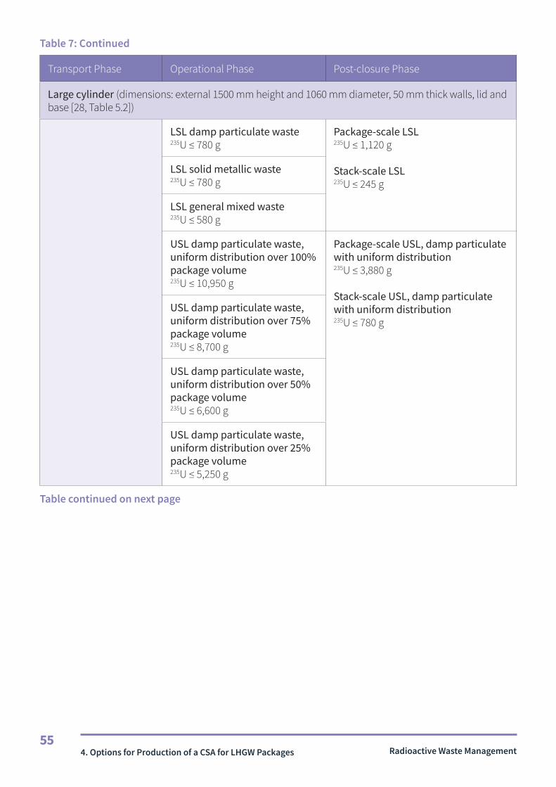
Radioactive Waste Management55
Table 7: Continued
Transport Phase Operational Phase Post-closure Phase
Large cylinder (dimensions: external 1500 mm height and 1060 mm diameter, 50 mm thick walls, lid and base [28, Table 5.2])
LSL damp particulate waste235U ≤ 780 g
Package-scale LSL235U ≤ 1,120 g
Stack-scale LSL235U ≤ 245 g
LSL solid metallic waste235U ≤ 780 g
LSL general mixed waste235U ≤ 580 g
USL damp particulate waste, uniform distribution over 100% package volume235U ≤ 10,950 g
Package-scale USL, damp particulate with uniform distribution235U ≤ 3,880 g
Stack-scale USL, damp particulate with uniform distribution235U ≤ 780 g
USL damp particulate waste, uniform distribution over 75% package volume235U ≤ 8,700 g
USL damp particulate waste, uniform distribution over 50% package volume235U ≤ 6,600 g
USL damp particulate waste, uniform distribution over 25% package volume235U ≤ 5,250 g
Table continued on next page
4. Options for Production of a CSA for LHGW Packages

Radioactive Waste Management56
Table 7: Continued
Transport Phase Operational Phase Post-closure Phase
Small cuboid (dimensions: external 1100 mm H x 1600 mm L x 1665 mm W, 50 mm thick walls, lid and base [28, Table 5.3])
LSL damp particulate waste235U ≤ 620 g
Package-scale LSL235U ≤ 1,020 g
Stack-scale LSL235U ≤ 245 g
LSL solid metallic waste235U ≤ 620 g
LSL general mixed waste235U ≤ 460 g
USL damp particulate waste, uniform distribution over 100% package volume235U ≤ 31,800 g
Package-scale USL, damp particulate with uniform distribution235U ≤ 12,580 g
Stack-scale USL, damp particulate with uniform distribution235U ≤ 2,520 g
USL damp particulate waste, uniform distribution over 75% package volume235U ≤ 25,900 g
USL damp particulate waste, uniform distribution over 50% package volume235U ≤ 20,700 g
USL damp particulate waste, uniform distribution over 25% package volume235U ≤ 19,150 g
Table continued on next page
4. Options for Production of a CSA for LHGW Packages

Radioactive Waste Management57
Table 7: Continued
Transport Phase Operational Phase Post-closure Phase
Large cuboid (dimensions: external 1700 mm H x 1600 mm L x 2000 mm W, 50 mm thick walls, lid and base [28, Table 5.4])
LSL damp particulate waste235U ≤ 620 g
Package-scale LSL235U ≤ 1,020 g
Stack-scale LSL235U ≤ 245 g
LSL solid metallic waste235U ≤ 620 g
LSL general mixed waste235U ≤ 460 g
USL damp particulate waste, uniform distribution over 100% package volume235U ≤ 35,550 g
Package-scale USL, damp particulate with uniform distribution235U ≤ 15,280 g
Stack-scale USL, damp particulate with uniform distribution235U ≤ 3,060 g
USL damp particulate waste, uniform distribution over 75% package volume235U ≤ 27,550 g
USL damp particulate waste, uniform distribution over 50% package volume235U ≤ 20,500 g
USL damp particulate waste, uniform distribution over 25% package volume235U ≤ 14,800 g
4. Options for Production of a CSA for LHGW Packages

Radioactive Waste Management58
4.4 Post-closure package envelope approach4.47 Deterministic assessments of LHGW packages result in the derivation of fissile material
limits using bounding pessimistic parameter values. In practice, this approach, whilst ensuring post-closure criticality safety, results in highly restrictive limits based on assessment of stylised and conservative post-closure scenarios occurring at very long timescales into the future. This approach may not yield an appropriate balance of risks arising from current waste processing and packaging operations and risks associated with potential criticality in a GDF in the distant future [7, §3.4.3]. Therefore, RWM’s recent research has focused on developing probabilistic assessments of post-closure criticality scenarios, which has led to the development of a generic ‘low-likelihood package envelope’ that establishes the packaging and disposal facility conditions under which post-closure criticality is considered unlikely to occur [39]. If waste producers can demonstrate compliance with this package envelope, then no further post-closure criticality safety assessment is required. Application of this methodology means that deterministic transport phase limits, rather than GDF post-closure phase limits, will be bounding in most cases.
4.48 Note that currently the RWM Nuclear Safety Security and Environment Committee (NSSEC) has only approved application of the probabilistic post-closure package envelope approach limits when the post-closure limit is not bounding. That is, if both the transport and operational phase fissile material limits are greater than the probabilistic post-closure limit, additional assessment of the packaging proposal currently needs to be undertaken by RWM. Work is ongoing to lift this constraint and apply the methodology in full.
4.49 The ‘package envelope’ approach provides an alternative option for deriving the post-closure fissile material limit for those packages that meet the envelope criteria. It encompasses most LHGW that is grout-encapsulated in 500 litre drums, 3 m3 boxes or 3 m3 drums and essentially represents an extension of the deterministic approach currently used in the gCSAs to derive waste package fissile material limits. However, rather than making worst case assumptions about parameter values with regard to the likelihood of criticality, a probabilistic approach has been taken in which uncertainties in parameters relating to waste package degradation and the relocation of fissile and other materials have been represented by distributions that are sampled in multiple realisations using probabilistic models. Bounding parameter values have been identified for which the minimum conditions for criticality are not achieved during a one million year assessment timeframe for any of 1,000 probabilistic calculations undertaken. That is, even accounting for extreme combinations of low probability parameter values captured in parameter value sampling, waste package evolution and the migration and relocation of fissile material would not result in criticality; this condition defines the target value RWM assumed for demonstrating the low likelihood of criticality.
4. Options for Production of a CSA for LHGW Packages

Radioactive Waste Management59
4.50 In the Likelihood of Criticality research project [24; 25], for LHGW packages from a small number of waste streams, it was not possible to demonstrate that the likelihood of post-closure criticality would be zero (based on the consideration of waste package evolution under disposal conditions) without imposing highly restrictive limits on the fissile material contents of waste packages. Therefore, RWM has identified limits on the fissile material contents of LHGW packages that will ensure that post-closure criticality is unlikely to occur, based on the models used and parameter value distributions adopted in the Likelihood of Criticality research project. That is, maximum fissile masses have been evaluated for which the target value assumed for the low likelihood of criticality is met.
4.51 Assumptions about the host rock and engineered barrier system characteristics and how they influence waste package evolution are important components of the package envelope definition. In this work [39], evaluation of the package envelope was based on RWM’s illustrative concept for the disposal of LHGW in vaults in HSR and assumptions about system evolution consistent with those made in the Likelihood of Criticality project. The assumed conditions bound those expected for disposal in LSSR and evaporite in terms of the analysis of the likelihood of post-closure criticality, based on the illustrative disposal concepts for such host rocks presented in the Technical Background Document of the generic DSSC [46].
4.52 The parameters that define the package envelope and the probabilistically-derived fissile material limits with which compliance must be demonstrated are summarised in Table 8.
4. Options for Production of a CSA for LHGW Packages

Radioactive Waste Management60
Probabilistic Package Envelope Parameters
Waste package characteristics — The waste container is a standard stainless steel 500 litre drum, 3 m3 box or 3 m3 drum.
— The wastes may contain the fissile radionuclides 239Pu or 235U, up to the derived fissile material limit. Other fissile radionuclides can only be present in insignificant amounts (gram quantities).
— Credit may be taken for the presence of 238U in the waste, which acts to dilute the fissile material and to absorb neutrons.
— The wastes are encapsulated and mixed with cementitious grout in the containers. — The wastes do not include materials that could preferentially accumulate fissile nuclides (such as a material that has a greater capacity for sorption of uranium and plutonium than the backfill).
Waste package performance under disposal conditions — Waste package behaviour under disposal conditions is captured by the parameter value distributions adopted in the modelling analysis. Requirements on waste package behaviour under disposal conditions are:- container corrosion rates in the range 10-5 to 10 μm/yr- plutonium solubility limits in the range 10-8 to 10-5 mol/m3
- uranium solubility limits in the range 10-8 to 10 mol/m3
- grout persists in the waste package such that gravitational slumping does not occur on a timescale of 1.3x10⁵ years.
GDF conditions — The conditions assumed in the illustrative disposal concept for the disposal of LHGW in vaults in higher strength rock bound the conditions in any future GDF. These conditions are primarily captured by parameter value distributions for groundwater flow through the vaults, and uranium and plutonium sorption distribution coefficients for the backfill.
Table 8: Parameters and fissile material limits for the probabilistic post-closure low likelihood of criticality package envelope [39].
Table continued on next page
4. Options for Production of a CSA for LHGW Packages

Radioactive Waste Management61
Table 8: Continued
Transport Phase Operational Phase Post-closure Phase
500 litre drum (dimensions: 1200 mm height, 800 mm diameter, 3 mm thick steel [39, Table 2.1])
INU (1.9 wt% 235U): 235U ≤ 1,250 g
LEU (4.0 wt% 235U): 235U ≤ 850 g
HEU (100 wt% 235U): 235U ≤ 550 g
Pu (100 wt% 239Pu): 239Pu ≤ 550 g
3 m3 box (dimensions: 1245 mm height, 1720x1720 mm area, 5.5 mm thick steel [39, Table 2.1])
INU (1.9 wt% 235U): 235U ≤ 2,200 g
LEU (4.0 wt% 235U): 235U ≤ 1,480 g
HEU (100 wt% 235U): 235U ≤ 960 g
Pu (100 wt% 239Pu): 239Pu ≤ 970 g
3 m3 drum (dimensions: 1245 mm height, 1720 mm diameter, 2.5 mm thick steel [39, Table 2.1])
LEU (4.0 wt% 235U): 235U ≤ 1,400 g
4. Options for Production of a CSA for LHGW Packages

Radioactive Waste Management62
4.5 Extension of the gCSA or package envelope approach4.53 Even if the package does not directly meet all of the GCSA or gCSA requirements, it may
still be possible to demonstrate that the waste package is bounded by assumptions made in the GCSA or a gCSA in terms of wasteform composition and waste package durability under GDF post-closure conditions. For example, it may be possible to argue that a larger volume package or one with thicker walls is bounded by the limits derived for a smaller/thinner package, as long as neutron reflection back into the package does not impact reactivity to a greater extent than determined in the original assessment. A further example would be if a LHGW package type is not planned to be stacked as high in a disposal vault, in which case the derived post-closure stack-scale limits would be bounding (i.e. fissile material would be contributed from fewer than the seven packages assumed in the slumping scenarios in the standard package gCSAs).
4.54 Extension of the package envelope could involve showing that, although the waste package does not meet all of the envelope criteria, its behaviour under disposal conditions is bounded (from a criticality safety perspective) by assumptions made about package behaviour in the analysis to derive the envelope criteria. For example, an alternative waste container and/or waste encapsulation/immobilisation matrix may be proposed, but it may be possible to demonstrate that the proposed waste package is at least as durable under disposal conditions as the grouted waste packages assumed in the analysis to derive the envelope criteria. Such a demonstration would imply that post-closure criticality is no more likely to occur for the proposed waste package than for the waste packages covered by the package envelope.
4.55 Alternatively, if bounding arguments cannot be made, the models used in the gCSA or in the analysis to derive the package envelope could be modified to include the proposed waste package, such that calculations could be undertaken to extend the gCSA or envelope criteria.
4.6 Development of a package-specific CSA4.56 A package-specific CSA must be developed where alternative waste packaging concepts
are proposed or the waste characteristics are not compatible with the assumptions made in the various RWM assessments, or it cannot be argued that those assessments are bounding of the proposed package. It is recommended that waste packagers seek advice from RWM at the earliest opportunity if a package-specific CSA is to be produced.
4.57 The main aim of a deterministic CSA is to demonstrate that a facility will remain within the ‘safe envelope’ of controlled parameters during all normal and credible accident conditions and for all credible criticality scenarios. The outcome of an assessment of a waste packaging proposal for LHGW will ultimately result in the definition of a single value for the maximum quantity of fissile materials that manufactured waste packages may be permitted to contain (the SFM). This derived value must ensure compliance with all of the regulatory requirements for the waste packages during their long-term management.
4. Options for Production of a CSA for LHGW Packages

Radioactive Waste Management63
4.58 The objective of a package-specific CSA is to determine a SFM that will have sufficient margin above the expected inventory to give confidence that the waste packages will be safe and acceptable for disposal. Development of a package-specific CSA may be undertaken to take account of specific information about the waste or package to justify an increased fissile material limit compared to limits derived in the gCSAs. For example, it may be possible to take account of the presence of specific neutron absorbing materials that may be assumed to have minimum values in the gCSA, or credit could be taken for knowledge of the distribution of fissile and other materials in the waste package or the specific composition and dimensions of containers. However, it would be necessary for the presence of such specific characteristics of the wasteform or container to be assured. Derivation of the SFM must be based on consideration of conditions during package transport and GDF operations and through assessment of post-closure criticality scenarios.
4.59 The calculations supporting the gCSAs are conservative and follow the general principle that if the value of a parameter is unknown then the most limiting value must be assumed. However, for the purpose of Disposability Assessment submissions, RWM considers that the selection of parameter values must reflect credible conditions, such that unrealistic combinations of worst-case assumptions and unnecessarily restrictive limits are avoided.
4.60 Key assumptions made in the derivation of the gCSA LSLs include:
— the maximum uranium enrichment (e.g. 1.9 wt% for INU wastes and 4 wt% 235U for LEU wastes);
— optimum (pitch and radius) lattice of uranium particles moderated by water or high-density polythene;
— non-uniformly distributed fissile material (a full or fractional fissile sphere occupying part of the container, in close proximity to adjacent waste packages, such that the fissile region is in the most reactive position in the container);
— the fissile region is assumed to be surrounded by nominal reflective shells of beryllium and graphite, or be subject to full graphite reflection; and
— the most limiting material is assumed to surround the fissile assembly in the container (e.g. water, polythene, steel, silicon dioxide or graphite) as appropriate.
4.61 If the objective of a package-specific CSA is to derive higher SFM values than those calculated in the gCSA, it is necessary to revise one or more of the assumptions made in the gCSA until an acceptable SFM (i.e. a value that meets the specified criticality safety criterion) can be calculated. The key to this approach is the robust justification of revised modelling assumptions, supported by reliable waste characterisation data and container specifications.
4.62 The assumption of optimally moderated fissile spheres in the model could be revised if it can be demonstrated that the waste is well mixed, which may be possible for a specific waste stream with known waste characteristics. In particular, any waste treatment process that avoids the presence of accumulations of fuel, for example, by removing any FED Magnox and packaging it separately and using assay techniques to confirm that the processing has been effective, would allow any high-fissile-content batches to be diverted. Process modifications, such as filling the containers and mixing the waste with grout in stages may also improve the assertion of a sufficiently well-mixed wasteform.
4. Options for Production of a CSA for LHGW Packages

Radioactive Waste Management64
4.63 Significantly higher SFMs could be derived if it can be demonstrated that the uranium enrichment in the waste is lower than that considered in the gCSA. For example, if the fissile material in the waste has a maximum enrichment of, say, 3 wt%, higher limits than derived in the 4 wt% 235U LEU gCSA may be possible.
4.64 The modelling assumption that there are no neutron absorbers or diluents in the RSC gCSA waste could be revised. The substantial quantities of metals, particularly steel, in some waste streams may prove beneficial from a criticality safety perspective. A guaranteed minimum amount of steel in each RSC package may enable higher SFM values to be derived if the steel is sufficiently well mixed to act as diluent and not a reflector. The gCSA for wastes containing plutonium assumed the presence of steel in compacted 200 litre drums packaged in 500 litre drums [38], and credit was taken for the presence of steel in Dounreay remote-handled ILW packages in a package-specific CSA [47].
4.65 A demonstrated absence of beryllium, graphite or polythene in the waste may enable derivation of a higher SFM. A guaranteed minimum presence of neutron poisons, such as chlorine in PVC, could help reduce system reactivity if present in sufficient quantity. However, it is recognised that there are other drivers to minimise chlorine in packages destined for the GDF. Further, guaranteeing the continued presence of a neutron poison in the waste during post-closure evolution as packages degrade may be challenging.
4.66 Finally, design aspects of the proposed package may help to reduce reactivity. If the container walls are sufficiently thick and/or include additional shielding (e.g. concrete), then neutron interaction between arrays of packages might be reduced and package lifetimes increased. The nature of the container and its contents, including the use of any encapsulating medium, may also enable justification of longer package lifetimes for the post-closure assessment - this allows increased time for plutonium decay and therefore enables greater initial plutonium masses to be disposed of.
4.67 Using specific knowledge of the wasteform and container, as exemplified in the above examples, enables the neutron transport models to be more realistic than those used in the gCSAs to represent broad ranges of waste packages. In turn this permits higher fissile mass limits to be calculated for the transport, operational and post-closure phases. The most restrictive of these limits determines the SFM for the proposed waste package.
4. Options for Production of a CSA for LHGW Packages

Radioactive Waste Management65
4.7 Revision of the waste packaging concept4.68 An alternative approach would be to modify the waste packaging concept to achieve
compliance with the envelope criteria or the requirements of the GCSA or a particular gCSA. A combination of a revised packaging concept and development of a package-specific CSA may also be applied. However, revision of the packaging concept may involve operations that expose workers to radiological risks deemed to be excessive in comparison with the potential risks of post-closure criticality in the GDF. That is, the approach may not satisfy the holistic principle of ensuring that risks are ALARP [57] or be consistent with the aim of using the Best Available Techniques (BAT) in waste package optimisation.
4.69 If revision of the waste packaging concept would not be ALARP then, on a case-by-case basis, and only for specific, low quantity, high fissile-content waste packages, it may be possible to consider a special emplacement strategy in the GDF. Selective emplacement of relatively high fissile-content waste packages (and control of the fissile material loading of waste packages stacked with such packages in a vault) is an option that can be used to achieve a relaxation of package fissile material limits derived from consideration of post-closure stack slumping scenarios. However, this is not a default option, nor a method to avoid restrictive post-closure safe fissile material limits, and may only be available for a small number of waste streams after it has been clearly demonstrated that all alternative options have been explored and would not be ALARP. Selective emplacement also places heavy reliance on managerial controls to ensure that it is implemented safely.
4.8 Consideration of arguments relating to the low consequence of criticality
4.70 It is recognised that uncertainties in waste package and disposal system evolution may be large in the very long term (hundreds of thousands of years) after disposal and thus arguments relating to the low consequence of post-closure criticality may become increasingly important to the GDF criticality safety case when considering such timescales. In some cases, when developing waste packaging solutions, ALARP considerations may drive a need to place increasing reliance on long-term low consequence arguments. That is, application of deterministically- or probabilistically-derived GDF post-closure fissile material limits or revision of the waste packaging concept to ensure that post-closure criticality is not credible or is of low likelihood in the very long term after disposal may introduce disproportionately high radiological and conventional safety risk to present-day workers.
4.71 However, any increased reliance on low consequence arguments to facilitate an increase in waste package fissile material content is only considered acceptable if it can be demonstrated that disposal of the proposed waste packages could only result in quasi-steady-state criticality events in the very long term and could not lead to rapid transient criticality. Generally, this means that a containment period in excess of 100,000 years is required for waste packages that contain substantial 239Pu masses, such that substantial 239Pu decay occurs before a fissile material accumulation can credibly develop in the GDF. RWM has provided explanations of quasi-steady-state and rapid transient criticality events [7, §2.1, §6.1].
4. Options for Production of a CSA for LHGW Packages

5. Criticality Safety Approach for HHGW Packages Radioactive Waste Management66
5.1 No decisions have yet been made on the packaging of HHGW for disposal. As potential disposal packages are at an early design stage, development and assessment of criticality safety controls for HHGW packages is less advanced than for LHGW packages. However, RWM is currently undertaking research in this area.
5.2 Spent fuel, separated plutonium and HEU wastes will contain higher concentrations of fissile radionuclides than those typically found in ILW. It may not be feasible to ensure criticality safety simply by placing limits on fissile mass or concentration in a HHGW package (as done for LHGW packages). Instead, it is likely that additional measures and analysis will be required to ensure and demonstrate criticality safety. For example, demonstration of criticality safety may require geometric constraints (i.e. on the design of the waste package) and constraints on the composition of the wasteform. Section 5.1 discusses the criticality safety constraints that may be applied to HHGW packages.
5.1 Potential Criticality Safety Constraints and Controls5.3 RWM is currently undertaking research on the development and assessment of
criticality safety constraints for HHGW packages. Research regarding HHGW criticality safety is discussed in the CSSR [7, §3.5 and §3.6]; a summary of possible criticality safety constraints and controls is presented here.
5.4 HHGW (excluding HLW) is likely to contain much higher concentrations and masses of fissile radionuclides than those typically found in ILW. As previously discussed, the majority of ILW packages will be designed to be sub-critical by limiting the fissile radionuclide mass, concentration and/or enrichment in each package, but application of this constraint alone may not be practicable when ensuring the criticality safety of spent fuel, separated plutonium and HEU waste packages. The design of the waste package will provide additional controls. Also, if the wasteform is sufficiently stable and corrosion-resistant (e.g. a ceramic spent fuel matrix surrounded by Zircaloy or stainless steel cladding, and ceramic separated plutonium and HEU matrices, potentially poisoned with hafnium and gadolinium) it may be possible to develop arguments that critical configurations are unlikely to occur after disposal. As future HHGW CSAs are expected to make use of specific knowledge about the content of each package, the wasteform and the package design, package-specific CSAs will need to be developed.
5. Criticality Safety Approach for HHGW Packages

Radioactive Waste Management67
5.5 To support the DSSC, HHGW packaging assumptions were made based on consideration of three illustrative geological disposal concept designs. Robust HHGW disposal packages were considered for these concepts, and it was assumed that the waste packages will be transported singly in a Disposal Container Transport Container (DCTC) and emplaced singly in tunnels or deposition holes. For the HSR illustrative concept, it was assumed that the disposal container will be a welded 50-mm-thick copper shell, with structural integrity provided by an internal cast iron insert (referred to as Variant 1). For the illustrative concepts designed for LSSR and evaporite it was assumed that the disposal container will be based on a carbon steel design (referred to as Variant 2), with greater internal voidage than Variant 1. However, RWM’s research on HHGW disposal container design is ongoing and alternative disposal concepts, such as multi-purpose containers (MPCs) for Pressurised Water Reactor (PWR) spent fuel management and alternative wasteforms for mixed oxide (MOX) fuel disposal are being considered.
5.6 RWM has examined possible DCTC design configurations for compliance with the criticality safety requirements of the IAEA Transport Regulations [48]. One package design feature that is being explored by RWM to ensure spent fuel packages remain sub-critical is the use of a high integrity package that has multiple high standard water barriers (see [10], para.680). Such a transport container would ensure that significant water ingress is excluded under challenging accident conditions that require the assumption that at least one containment barrier has failed during an accident scenario. Therefore, using multiple water barriers ensures that even if one containment barrier were to fail, water still cannot access the container contents and increase system reactivity.
5.7 Another possible option is the inclusion of neutron poisons in the package, although their persistence during transport and operational accident conditions, and during post-closure package degradation, would need to be demonstrated.
5.8 HHGW disposal containers will be removed from their transport container (the DCTC) at some point prior to their emplacement in the disposal facility. This means that an argument based on the use of multiple water barriers in the transport phase may not be directly transferable to all stages of the GDF’s operational phase. Therefore, alternative criticality safety control measures or arguments will be required.
5.9 Criticality safety assessments for spent fuel typically assume that the fissile material is in its most reactive condition, which is usually at maximum enrichment with no irradiation. Fission products and actinides are formed during irradiation of the fuel in the reactor, a process which also tends to reduce the overall concentration of fissile material. Accounting for the resulting reduction in fuel reactivity is known as ‘burn-up credit’ and can provide significant increases in derived safe fissile material limits [49]. RWM is currently undertaking research on the use of burn-up credit arguments, which are considered important for demonstrations of criticality safety following spent fuel disposal. However, such arguments require a detailed record of the spent fuel irradiation history and significant management control. It may not be possible to meet such an assurance requirement for some historic spent fuels.
5.10 In summary, a range of criticality safety constraints and design measures could be adopted as part of a demonstration of criticality safety during HHGW transport and disposal operations [50]. Potential criticality safety controls include neutron absorbing materials with neutron flux traps, development of robust wasteform matrices, void fillers to limit water ingress, and multiple water barriers. Also, the criticality safety case for spent fuel management could be based on burn-up credit arguments and associated confirmation requirements [51].
5. Criticality Safety Approach for HHGW Packages

68Part 2 – Preparation of Criticality Compliance Assurance Documentation
Radioactive Waste Management
Part 2
Preparation of Criticality Compliance Assurance Documentation

Radioactive Waste Management69
6.1 Background6.1 As discussed in Part A, the demonstration of criticality safety through each phase of
waste management requires development of suitable constraints on the packaging of fissile wastes, which are derived through use or production of a CSA. The waste package CSA, along with assurances that wastes will be packaged in a way that is compliant with the criticality safety constraints derived in the CSA and records of compliance for packaged wastes, will support the arguments and evidence base for the overall safety case for the GDF.
6.2 This part of the guidance addresses the information required from waste packagers to demonstrate that sufficiently robust waste packaging procedures and process controls will be in place to ensure compliance with the criticality safety constraints derived in the CSA. This information must be provided in the form of Criticality Compliance Assurance Documentation (CCAD).
6.2 CCAD Requirements6.3 RWM has defined the assurance requirements [13] that will need to be met by the
information presented in the waste package CCAD:
C168 Assurance shall be provided that the fissile content, and other constraints, of each waste package to be produced, is within the limits prescribed in the associated CSA.
C169 Supporting documents referenced within the justification for criticality compliance assurance arguments shall be included in the Package Record Specification.
C170 Each iteration of the Criticality Compliance Assurance Documentation, against which waste packages were made shall be retained and recorded in the CCAD section of the Package Records Specification.
C171 Assurance of criticality compliance shall be described in a manner that is easily identifiable as the Criticality Compliance Assurance Documentation.
6. The Basis for Criticality Compliance Assurance Documentation
6. The Basis for Criticality Compliance Assurance Documentation

Radioactive Waste Management70
C172 The description of criticality compliance assurance shall:
a. State the basis for assessment including: the safe fissile mass from each phase, the overall safe fissile mass that is being packaged to and any other constraints detailed in the criticality safety assessment that must be complied with. (See Section 8.1)
b. Identify the arrangements that are used to ensure compliance with the constraints in the Criticality Safety Assessment (e.g. plant processes, controls, assay arrangements). (See Section 8.2.1)
c. Identify the uncertainties that may result in the constraints in the Criticality Safety Assessment being exceeded. (See Section 8.2.2)
d. Identify any potential faults that could result in the constraints in the Criticality Safety Assessment not being complied with. (See Section 8.2.3)
e. Identify mitigation measures (controls) for each identified fault or uncertainty. (See Sections 8.2.2 and 8.2.3)
f. Explain how the arrangements and controls required to ensure criticality safety will be implemented within the management system and appropriate records generated. (See Sections 8.2.1, 8.2.2 and 8.2.3)
C173 The description of assurance arrangements shall be approved by an individual with sufficient knowledge of the operation of the packaging plant.
6.4 Note that RWM is primarily concerned with assurance of compliance with the most limiting waste packaging constraints derived in CSAs that consider conditions during waste package transport to the GDF, during disposal operations and after GDF closure. However, the criticality safety constraints associated with waste package production, handling and storage could be more restrictive than those associated with waste package transport and disposal, and the CCAD must identify the most limiting phase.
6.5 Preparation of the information needed to meet the assurance requirements is likely to require collaborative working between criticality safety specialists and experienced waste packaging plant personnel in order to ensure that the CCAD is based on sufficient understanding of the derived criticality safety constraints and an authoritative assessment of potential packaging process uncertainties and faults and their mitigation. However, the work involved in meeting these requirements and the type of information to be provided will depend on the type of criticality safety constraints to be implemented, as discussed further in Section 7.
6. The Basis for Criticality Compliance Assurance Documentation

Radioactive Waste Management71
7.1 The amount and detail of information to be provided in the CCAD will depend on the criticality safety constraints that need to be implemented. These may vary substantially between different waste packaging proposals because of differences in the nature and quantities of fissile and other materials expected to be present in the wastes. Therefore, it is recommended that a proportionate approach is taken to producing the CCAD, where information provision is focused on assurances that constraints associated with the criticality safety claims and arguments specific to the proposed waste packages will be implemented.
7.2 For example, if a waste stream includes no fissile material, then very few waste package criticality safety constraints are needed. It will only be necessary to ensure that controls are in place to prevent mixing with other waste streams that may contain fissile material. If the CSA determines that waste package criticality safety constraints are necessary, then the CCAD must focus on identifying the waste packaging arrangements that will ensure implementation of the constraints. The CCAD must also identify uncertainties and credible faults that could result in non-compliance with those constraints (e.g. undetected failure to comply with fissile mass limits) and must describe how the uncertainties will be taken into account and arrangements will be made to mitigate the faults to ensure that non-compliances will not occur. The approach is summarised in the flow chart shown in Figure 5. Indicative examples of how the information to be provided in the CCAD is proportionate to the nature and quantity of fissile material in the waste stream is shown in Table 9.
7. Proportional Approach to Preparing Criticality Compliance Assurance Documentation
7. Proportional Approach to Preparing Criticality Compliance Assurance Documentation

Radioactive Waste Management72
Figure 5: Suggested outline of CCAD based on the proportionate approach
7. Proportional Approach to Preparing Criticality Compliance Assurance Documentation
Nature and quantity of fissile material
The waste stream contains no fissile material (example 1 in Table 9)
Arguments and evidence to support the claim that waste package criticality safety constraints are unnecessary
Description of arrangements to ensure that mixing with wastes that include fissile material cannot occur
Arguments and evidence to support the claim that waste package criticality safety constraints are unnecessary
Description of arrangements to ensure that mixing with other wastes that include fissile material cannot occur
Statement of waste package criticality safety constraints derived in the CSA
Description of the packaging arrangements that will ensure that criticality safety constraints are met and why uncertainties and credible faults in the packaging process could not result in non-compliance
Statement of waste package criticality safety constraints derived in the CSA
Description of the packaging arrangements that will ensure that criticality safety constraints are met, including mitigation measures to ensure that uncertainties and credible faults in the packaging process could not result in non-compliance
Less than critical mass or concentration of fissile mass in waste stream
(example 2 in Table 9)
Maximum fissile mass in waste package much less than waste package SFM
(example 3 in Table 9)
Maximum fissile mass in waste packages is close to the waste package SFM
(example 4 in Table 9)
Main CCAD components
Yes
Yes
No
No
No
Yes
Yes

Radioactive Waste Management73
Table 9: Examples to illustrate the proportionality of information provided in the CCAD to the nature and quantity of fissile material in proposed waste packages.
Nature and quantity of fissile material Main components of CCAD
1. The entire waste stream contains no fissile material.
Claim that no criticality safety constraints are required for the proposed waste packages, with reference to the evidence that demonstrates that the entire waste stream contains no fissile material.
Provide assurances that packaging plant processing faults involving mixing of wastes from different waste streams would not be credible.
2. The entire waste stream contains less than a minimum critical mass or concentration of fissile material (bearing in mind factors such as the range of fissile isotopes that may be present and the enrichment).
Claim that no criticality safety constraints are required for the proposed waste packages. Provide references to the underpinning criticality safety arguments and evidence that demonstrate that the entire waste stream contains less than a minimum critical mass or concentration of fissile material and that the waste packages would remain sub-critical when exposed to credible conditions associated with transport and disposal (including post-closure conditions). Include the evaluation of the minimum critical mass or concentration based on assessment of a credible bounding configuration (e.g. the critical mass of fissile radionuclides at the relevant enrichment in a water-moderated, water-reflected sphere, or the critical concentration of fissile material in non-fissile material).
Provide assurances that packaging plant processing faults involving mixing of wastes from different waste streams would not be credible.
3. The expected maximum waste package fissile material content is substantially below the SFM for the waste package.
State the SFM for the waste packages, as well as any associated packaging constraints, such as on enrichment, encapsulation, the type of container used and the quantities of other materials in the waste package (e.g. neutron reflectors). Include references to the underpinning CSA.
Describe the waste packaging arrangements that will ensure that the criticality safety constraints are met.
Show that there are no uncertainties or credible faults in the packaging process that could result in the SFM being exceeded, with reference to any underpinning analysis and evidence.
4. Some waste packages will contain fissile masses that are close to the SFM.
State the SFM for the waste packages, as well as any associated packaging constraints, such as on enrichment, encapsulation, the type of container used, the fissile material distribution in the wasteform, and the quantities of other materials in the waste package that need controlling (e.g. neutron moderators and reflectors). Include references to the underpinning CSA.
Describe the waste packaging arrangements that will ensure that the criticality safety constraints are met.
Identify uncertainties and credible faults in the packaging process that could result in the SFM being exceeded or other criticality constraints being challenged, especially for the waste packages that contain relatively large fissile masses. Refer to underpinning analysis and evidence.
Describe how the uncertainties will be taken into account and how controls will be in place to avoid or mitigate faults such that non-compliances do not occur.
7. Proportional Approach to Preparing Criticality Compliance Assurance Documentation

Radioactive Waste Management74
8. Content of Criticality Compliance Assurance Documentation
8.1 A draft of the CCAD would not be expected until at least the Interim stage of the waste package Disposability Assessment process (see Section B5), once any waste package criticality safety constraints have been proposed through preparation or application of a CSA. The Final stage submission is expected to include the complete and approved CCAD. However, waste packagers are encouraged to engage with RWM prior to development of the draft CCAD in order to agree its content in relation to the nature and quantity of the fissile material and the information needed regarding arrangements for implementing any waste package criticality safety constraints.
8.2 Note that the CCAD will form part of the waste package record that will accompany and facilitate acceptance of the waste package through all stages of its management. Therefore, CCAD will need to be provided irrespective of the fissile material content of the waste stream to be packaged. However, an important implication of a proportionate approach to producing the CCAD is that the scope of the CCAD may differ greatly between different waste packaging proposals, dependent on the waste package criticality safety constraints, if any, required. If the proposed waste packages are expected to contain little or no fissile material (as in the first two examples shown in Table 9), then it may be sufficient for the CCAD to state that no waste package criticality safety constraints are required, with reference to underpinning arguments and evidence, taking account of any uncertainties and credible faults that could challenge the arguments and evidence. For the other examples shown in Table 9, descriptions will be required of the packaging arrangements that will be in place to ensure that the criticality safety constraints are met, including discussion of any uncertainties or credible faults in the packaging process that could result in non-compliance with any of the constraints and how such non-compliances will be avoided.
8.3 It is recognised that some information required in the CCAD may be provided elsewhere in the waste packaging proposal submission documents. Rather than duplicate information in the submission, the CCAD may refer to specific sections within other documents. Alternatively, the CCAD may be included as part of another submission document, such as the Waste Product Specification (WPrS) [52, §7.1]. It is important that cross-referencing to and from the CCAD is clear and precise so that the arguments and evidence relevant to criticality compliance assurance are readily traceable. Accurate cross-referencing will facilitate the criticality evaluation in RWM’s Disposability Assessment process and will help to ensure that information about waste package criticality safety constraints is readily accessible to those involved in developing and scrutinising the criticality safety case for the GDF in the future.
8. Content of Criticality Compliance Assurance Documentation

Radioactive Waste Management75
8.4 The information to be included in the CCAD is described in the following sub-sections, covering the three main components of the CCAD:
— identification of criticality safety constraints (Section 8.1);
— arrangements for criticality compliance assurance (Section 8.2); and
— definition of waste package records (Section 8.3).
8.5 The information to be provided with regard to these three components depends on the fissile material content of the waste packages, as described in Section 7.
8.1 Identify Criticality Safety Constraints8.6 The first part of the CCAD must provide information about the waste stream(s) of concern and
any criticality safety constraints, including the SFM, associated with packaging the wastes. The limiting constraints when considering waste package production, storage and transport, GDF operations and the GDF post-closure phase must be identified. If no waste package criticality safety constraints are required, then the arguments and evidence to support such a claim must be provided.
8.7 The inventory information to be provided will depend on the nature and quantity of the waste stream(s), especially the fissile material content, but may include:
— the identity of the waste stream(s) relevant to the waste packaging submission;
— the masses of plutonium and uranium isotopes and any fissile isotopes other than 233U, 235U, 239Pu and 241Pu expected to be present in the waste stream(s) at the time of disposal, and the masses of any precursors to fissile isotopes;
— the 235U enrichment or the effective enrichment in terms of the 235U and plutonium content;
— the inventory of other materials in the waste that are of relevance to criticality safety (i.e. efficient neutron moderators such as polythene or deuterated material, neutron reflectors such as graphite and beryllium, and/or materials that could provide favourable sites for sorption of fissile radionuclides).
8.8 Information must then be provided about the waste packaging constraints relevant to ensuring that all criticality safety requirements are met for the waste stream(s) of concern. For waste packages that include fissile material, the CSA will describe the basis of the assessment that underpins the derivation of the SFM. The basis of the assessment comprises assumptions made in the CSA about the proposed waste packaging concept that translate to waste packaging constraints. These constraints will need to be met to ensure that application of the SFM remains valid. Thus, if an SFM has been derived for a waste packaging proposal, it must be listed alongside any other associated waste packaging constraints, which may include:
— the type of waste container used (e.g. 500 litre drum, 3 m3 box, 3 m3 drum);
— the properties of the container (e.g. material properties and minimum dimensions and thicknesses);
— the mass and type of immobilisation matrix and/or entombment material (e.g. grout annulus);
— the enrichment (or effective enrichment) of uranium in the waste package;
— the distributions of fissile and non-fissile material in the waste package;
— the neutron moderator and reflector material content of the waste package;
— effective sorbing materials in the waste package.
8. Content of Criticality Compliance Assurance Documentation

Radioactive Waste Management76
8.9 Note that specific categories of fissile wastes have been assessed in generic CSAs (gCSAs) and as part of the derivation of the low-likelihood package envelope (as discussed in Section 4). Application of the gCSAs or the package envelope for wastes that contain irradiated natural uranium (INU) or low enriched uranium (LEU) have particular requirements on the form and origin of the wastes:
— for wastes assumed to contain INU, evidence must be provided that the wastes contain irradiated uranium metal fuels from Magnox reactors, where the original enrichment was no more than 0.92% 235U by weight;
— for wastes assumed to contain LEU, evidence must be provided that the wastes contain residues of irradiated UO2 fuels, where the original fuel enrichment was no more than 4% 235U by weight.
8.10 As noted in Section 7, the extent of information required in this part of the CCAD is proportionate to the nature and quantity of the fissile material in the waste stream(s) and the criticality constraints, if any, derived to support the waste packaging concept. The goal for the information provided is that it must be sufficient to enable a clear understanding of the constraints that need to be implemented in the packaging process, thereby serving as a basis for the analysis of packaging uncertainties and faults and identification of records requirements relevant to criticality safety.
8.2 Describe Arrangements for Criticality Compliance Assurance
8.11 This section describes the information that must be provided in support of a criticality compliance assurance demonstration, covering the proposed waste treatment and packaging process, treatment of uncertainties, identification and mitigation of potential packaging faults, and management systems to ensure that relevant controls in the packaging process are implemented.
8.2.1 Describe arrangements for implementing criticality constraints
8.12 Information on the proposed waste treatment and packaging process must be provided or cited in order to give a basic understanding of the operation of the waste packaging plant and process. The engineered (or other) safety systems and controls that will be used to ensure that the waste package criticality safety constraints are implemented must be identified. This must include descriptions of any arrangements that will need to be in place to ensure that the amounts of fissile and other materials in each waste package are controlled as necessary (e.g. sampling, measurements, fissile material monitoring and assay systems), with reference to relevant management and operational procedures.
8.13 Empirical evidence from plant operations, commissioning activities or trials can be included in the CCAD to support the criticality safety demonstration. For example, information on trials related to the commissioning of systems to demonstrate fissile material distributions in an immobilisation matrix, and on fissile material assay and monitoring systems, is likely to be of importance where relevant to the implementation of criticality safety constraints. Such evidence may be particularly beneficial if it indicates that there would be large margins to the SFM under normal operating conditions.
8. Content of Criticality Compliance Assurance Documentation

Radioactive Waste Management77
8.14 Note that the fissile and other relevant material content of a waste package will need to be confirmed before any waste conditioning, because meaningful measurements cannot be made after conditioning.
8.15 The use of in-process monitoring, where available, is useful as an advance indicator of the potential for exceeding the SFM. For example, upstream samples could be monitored for alpha-activity, which could be assumed to correspond to fissile species. Although this is a highly pessimistic determination of fissile material content it does provide an early ‘trigger level’ for higher than expected fissile material content and the potential need for remedial action to be taken if proved necessary by subsequent measurement of the actual fissile content of the waste.
8.2.2 Identify, assess and account for uncertainties
8.16 Uncertainties associated with the waste packaging process that could result in failure to meet one or more of the criticality safety constraints, such as the SFM, must be identified. These uncertainties are likely to include, but are not limited to:
— monitoring errors including random errors (to three standard deviations) and systematic errors;
— sampling errors (to three standard deviations);
— uncertainties in sample variability;
— uncertainties in waste records;
— uncertainties in metering waste into the container.
8.17 Uncertainty identification and evaluation must follow a systematic and structured approach, resulting in a list of uncertainties with references to relevant operating procedures or instructions, measurement method statements, instrument calibration certificates etc that state the uncertainties.
8.18 A description must be provided of how the packaging process will be controlled such that, even if all of the worst-case uncertainties are added together, any packaging constraints, such as the SFM, will be met. Examples of approaches that could be taken to account for uncertainties in order to ensure that the SFM is not exceeded are:
i. In the case of heterogeneous wastes, where a number of discrete batches of waste containing fissile material are added to a waste container prior to encapsulation, a suitable approach would be to adjust assayed values of the fissile material content of individual batches upwards to represent the maximum possible fissile content when all measurement uncertainties are taken into account. Further batches could be added to the waste container to the limit defined by the SFM;
ii. For homogeneous wastes, such as sludges, the identified uncertainties could be combined in the determination of fissile content of the raw waste and applied to the SFM to produce a value for a safe working limit, which would be less than the SFM by a margin that ensures that the actual waste package fissile material content is less than the SFM.
8. Content of Criticality Compliance Assurance Documentation

Radioactive Waste Management78
8.2.3 Identify, assess and mitigate faults
8.19 Potential faults or errors in the packaging process that could lead to non-compliance with waste package criticality safety constraints, such as the SFM, must be identified and assessed. The scope and type of fault assessment to be undertaken must relate to the criticality safety constraints to be imposed. If no waste package criticality safety constraints are needed, then it is only necessary to document the arrangements that will be in place to prevent mixing with other waste streams that may contain fissile material.
8.20 If there are expected to be large margins to a waste package SFM, then it may be possible to argue that it is not credible for any fault to lead to the SFM being exceeded based on evidence about the expected maximum fissile material content of the waste packages and the packaging process. Otherwise, a formal fault identification process, such as a hazard and operability study (HAZOP) or hazard identification process (HAZID) may be required, where faults are identified in the package production process in such a manner as to allow the definition of control mechanisms for their elimination. Typical faults include human error, monitoring and sampling faults, overbatching (i.e. undetected failure to comply with specified limits on fissile or other materials that affect criticality safety) or the absence of waste package features for which credit is taken in the criticality safety assessment (e.g. a grout annulus).
8.21 A summary must be provided of the controls and mitigation measures that will be in place to ensure that faults could not result in non-compliance with waste package criticality safety constraints. Evidence to support fault mitigation arguments must be provided and may include references to conditions for waste acceptance and operating procedures for the waste packaging facility.
8.3 Define Waste Package Data to be Recorded8.22 The data to be recorded for each waste package relating to demonstration of
compliance with the criticality safety constraints associated with the waste package must be identified, or references made to where the information to be recorded is identified, such as sections of the WPrS.
8. Content of Criticality Compliance Assurance Documentation

Radioactive Waste Management79
References
1. NDA, Geological Disposal: An Overview of the RWM Disposability Assessment Process, Nuclear Decommissioning Authority, WPSGD No. WPS/650/03, April 2014.
2. RWM, Geological Disposal: Waste packages and the Assessment of their Disposability, NDA Report DSSC/441/01, December 2016.
3. RWM, Geological Disposal: Overview of the generic Disposal System Safety Case, NDA Report DSSC/101/01, December 2016.
4. RWM, Geological Disposal: Generic Transport Safety Case – Main Report, NDA Report DSSC/201/01, December 2016.
5. RWM, Geological Disposal: Generic Operational Safety Case – Main Report, NDA Report DSSC/202/01, December 2016.
6. RWM, Geological Disposal: Generic Environmental Safety Case – Main Report, NDA Report DSSC/203/01, December 2016.
7. RWM, Geological Disposal: Criticality Safety Status Report, NDA Report DSSC/458/01, December 2016.
8. RWM, Geological Disposal: Generic Guidance on the Preparation of Submissions for the Disposability Assessments of Waste Packaging Proposals, WPS/908/05, July 2016.
9. NDA, Geological Disposal: Guidance on Application of the Criticality Safety Requirements of the IAEA Transport Regulations for Waste Packages that Contain Small Quantities or Concentrations of Fissile Material, WPS/911/03, 2019.
10. International Atomic Energy Agency, Regulations for the Safe Transport of Radioactive Material, 2012 Edition, Specific Safety Requirements No. SSR-6.
11. RWM, Geological Disposal: Waste Package Data and Information Recording Requirements: Explanatory Material and Guidance, WPS/850/03, December 2015.
12. RWM, Geological Disposal: Disposal System Specification Part B: Technical Specification, NDA Report DSSC/402/01, December 2016.
13. RWM, Specification for Waste Packages Containing Low Heat Generating Waste: Part C – Fundamental Requirements, RWM Report WPS/220/01, 2019.
14. RWM, Specification for Waste Packages Containing Low Heat Generating Waste: Part D – Container Specific Requirements, RWM Report WPS/300/04, 2019.
15. International Atomic Energy Agency, Application of the Revised Provisions for Transport of Fissile Material in the IAEA Regulations for the Safe Transport of Radioactive Material, 2012 Edition, IAEA-TECDOC-1768.
References

Radioactive Waste Management80
16. RWM, Geological Disposal: Waste Package Accident Performance Status Report, NDA Report DSSC/457/01, December 2016.
17. International Atomic Energy Agency, Advisory Material for the IAEA Regulations for the Safe Transport of Radioactive Material (2012 Edition), Specific Safety Guide No. SSG-26, 2014.
18. ONR, Criticality Safety Assessment of Transport Packages, ONR Transport Technical Assessment Guide NS-TAST-GD-097, Revision 0, April 2017. Available from http://www.onr.org.uk/operational/tech_asst_guides/ns-tast-gd-097.pdf.
19. Transport Container Standardisation Committee, Agreed Position on Low Temperature Criticality, TCSC Paper P296, Issue 1, 1 March 2017.
20. T. Ware and D. Hanlon, Research into the Effect of Temperature on the Criticality Safety of Fissile Systems, Wood Report Reference 203171-AA-0022, Issue 2, March 2019.
21. RWM, Geological Disposal: Generic Disposal Facility Design, NDA Report DSSC/412/01, December 2016.
22. RWM, Geological Disposal: Engineered Barrier System Status Report, NDA Report DSSC/452/01, December 2016.
23. RWM, Geological Disposal: Waste Package Evolution Status Report, NDA Report DSSC/451/01, December 2016.
24. T.W. Hicks and T.D. Baldwin, Likelihood of Criticality: The Likelihood of Criticality Synthesis Report. AMEC Report 17293-TR-023 to the NDA, Galson Sciences Limited, Oakham, Report 1124-27, Version 2, 2014.
25. T.W. Hicks, T.D. Baldwin, J.M. Solano and D.G. Bennett, Likelihood of Criticality: The Likelihood of Criticality Following Disposal of LLW/ILW/DNLEU, AMEC Report 17293-TR-021 for the Nuclear Decommissioning Authority, Version 2, 2014.
26. T.W. Hicks, T.D. Baldwin, J.M. Solano and D.G. Bennett, Likelihood of Criticality: The Likelihood of Criticality Following Disposal of HLW/SF/HEU/Pu, AMEC Report 17293-TR-022 for the Nuclear Decommissioning Authority, Version 2, 2014.
27. T.W. Hicks, FEPs and Scenarios for Developing Criticality Screening Levels, Galson Sciences Ltd, Report 0465-2, Version 2, 2007.
28. T.W. Hicks and T.D. Baldwin, A Generic Criticality Safety Assessment for Irradiated Natural and Low-enriched Uranium Wastes Packaged in Robust Shielded Containers: Volume 1 – Assessment, Galson Sciences Ltd, Report 1241-5, Version 2, 2013.
29. AMEC, MONK: User Guide for Version 9A, ANSWERS/MONK/Report005.
30. Los Alamos National Laboratory, MCNP - A General Monte Carlo N-Particle Transport Code, Version 5, Volume I: Overview and Theory, LA-UR-03-1987, Revised 2008.
31. J. Venner, R.M. Haley and R. L. Bowden, K-Effective as a Measure of Criticality Safety, JAERI Conference, 2003.
32. Handbook of Criticality Data for Plant Designers and Operators, AHSB(S) HANDBOOK 1, UKAEA 1960.
33. N.L. Provost and H.C. Paxton, Nuclear Criticality Safety Guide, LA-12808 UC-714, September 1996.
34. T.W. Hicks, The General Criticality Safety Assessment, Galson Sciences Ltd, Report 0914-1, Version 1.1, 2009.
References

Radioactive Waste Management81
35. T.W. Hicks, Criticality Safety Assessment for Waste Packages Containing Irradiated Natural Uranium, Galson Sciences Ltd, Report 0560-1 Version 1.1, 2007.
36. T.W. Hicks, Criticality Safety Assessment for Waste Packages Containing Low-enriched Uranium, Galson Sciences Ltd, Report 0465-4 Version 2, 2007.
37. T.W. Hicks, Criticality Safety Assessment for Waste Packages Containing High-enriched Uranium, Galson Sciences Ltd, Report 0560-3 Version1, 2007.
38. T.W. Hicks, Criticality Safety Assessment for Waste Packages Containing Separated Plutonium, Galson Sciences Ltd, Report 0560-2 Version 1.1, 2007.
39. T.W. Hicks and S. Doudou, Development of a Methodology for Defining Waste Package Characteristics that Ensure Long-term Criticality Safety in a Geological Disposal Facility, Galson Sciences Ltd, Report 1402-4, Version 3.3, September 2015.
40. R.M. Mason, P.N. Smith and D. Holton, Modelling of Consequences of Hypothetical Criticality: Synthesis Report for Post-closure Criticality Consequence Analysis. AMEC Report, AMEC/SF2409/013, Issue 2, March 2014.
41. R.M. Mason and P.N. Smith, Modelling of Consequences of Hypothetical Criticality: Post-closure Criticality Consequence Analysis for ILW, LLW and DNLEU Disposal. AMEC Report AMEC/SF2409/011, Issue 3, 2015.
42. R.M. Mason and P.N. Smith, Modelling of Consequences of Hypothetical Criticality: Post-closure Criticality Consequence Analysis for HLW, Spent Fuel, Plutonium and HEU Disposal. AMEC Report AMEC/SF2409/012, Issue 3, 2015.
43. Nirex, The Development of a General Criticality Safety Case for Intermediate and Low Level Waste in a Deep Waste Repository, T/PAP/3/I/01, 1997.
44. T. W. Hicks, Generic Waste Stream Definitions for Developing Criticality Screening Scenarios, Galson Sciences Limited Report to the NDA, 0465-1, Version 3, March 2007.
45. Nirex, Design Safety Report RSTC-285 with 500 Litre Drums as Contents Package Design No 3850A, UK Nirex Ltd Report T/REP/20395, May 1998.
46. RWM, Geological Disposal: Technical Background to the Generic Disposal System Safety Case, NDA Report DSSC/421/01, December 2016.
47. T. Page, Package Specific Criticality Safety Cases for the Transport and Operational Phases of the Packaging of Dounreay RHILW, Nuclear Technologies report NT/P509/R276, Issue 3, December 2007.
48. P. Purcell, Criticality Solution for the Transport of Spent Fuel, Plutonium and Highly Enriched Uranium, INS report TD/ETS/R/12/271Rev 0, May 2012.
49. American Nuclear Society, Burnup credit for LWR fuel, American National Standard ANSI/ANS-8.27-2008, American Nuclear Society, 2008.
50. T.W. Hicks, S. Doudou and W.S. Walters, Demonstrating the Criticality Safety of Spent Fuel Disposal, Galson Sciences Report 1649-5, Version 3.1, January 2018.
51. T.W. Hicks and T.D. Baldwin, Review of Burn-up Credit Applications in Criticality Safety Assessments for Spent Fuel Management and Disposal, Galson Sciences Report 1649-4, Version 3.1, January 2018.
52. RWM, Geological Disposal: Waste Packages and the Assessment of their Disposability, NDA Report DSSC/441/01, December 2016.
References

Radioactive Waste Management82
Credible eventAn event that is possible in that it has a non-trivial likelihood of occurrence.
CriticalityA state in which a quantity of fissile material can maintain a self-sustaining neutron chain reaction; the number of neutrons being produced by fission is equal to the numbers being lost by absorption and leakage.
Deterministic calculationsCalculations in which all parameters take a single, fixed value.
Fissile materialFissile material is that which undergoes fission when irradiated with thermal energy neutrons. The IAEA Transport Regulations define fissile material as material containing any of the fissile nuclides 233U, 235U, 239Pu and 241Pu.
Geological disposalA management option involving the emplacement of radioactive waste in an engineered underground geological disposal facility or repository, where the geology (rock structure) provides a barrier against the escape of radioactivity and there is no intention to retrieve the waste once the facility is closed.
Geological disposal facility (GDF)An engineered underground facility for the disposal of solid radioactive wastes.
High Heat Generating Waste (HHGW) HHGW includes high-level waste (HLW), spent fuel, separated plutonium and high-enriched uranium (HEU).
Incredible event/not credibleWhere the probability of an event occurring is expected (or has been demonstrated) to be vanishingly small or zero.
Low Heat Generating Waste (LHGW)LHGW includes low-level waste (LLW) destined for disposal in the GDF, intermediate-level waste (ILW) and depleted, natural and low-enriched uranium (DNLEU).
Appendix A – Glossary
Appendix A – Glossary

Radioactive Waste Management83
Neutron multiplication factor, Keffective
How close a system is to being critical is defined by the neutron multiplication factor, Keffective, which is the ratio of the rate of neutron production by fission to the rate of neutron losses (by absorption and leakage). At the point of criticality Keffective is equal to one. For super-critical systems Keffective is greater than one, and it is less than one for sub-critical systems.
Probabilistic calculationsCalculations in which many individual realisations are carried out; in each realisation some or all parameters take a randomly sampled value from a probability density function (PDF) representing the uncertainty in the parameter.
ReactivityThe reactivity of a fissile system is a measure of the departure of Keffective from one, being less than zero when the system is sub-critical.
Transport packageThe complete assembly of the radioactive material and its outer packaging, as presented for transport.
Waste containerAny vessel used to contain a wasteform for disposal.
WasteformThe waste in the physical and chemical form in which it will be disposed of, including any conditioning media and container furniture (i.e. in-drum mixing devices, dewatering tubes, etc.), but not including the waste container itself or any added inactive capping material.
Waste packageThe product of conditioning that includes the wasteform and any container(s) and internal barriers (e.g. absorbing materials and liner), as prepared in accordance with requirements for handling, transport, storage and/or disposal.
Waste packagerAn organisation responsible for the packaging of radioactive waste in a form suitable for transport and disposal.
Appendix A – Glossary

Radioactive Waste Management84
Appendix B – General Principles and Requirements for Criticality Safety
B1 Introduction
This appendix provides background information on the nature of the criticality hazard and describes the regulatory framework within which the requirements for the criticality safety of geological disposal are set and addressed.
Section B2 describes how criticality safety constraints are applied to prevent the occurrence of a nuclear chain reaction, which includes constraints on factors such as the mass of fissile material in a waste package and on the geometry of the waste package.
Section B3 summarises criticality safety regulation in the UK, including the different regulatory responsibilities for waste package transport, GDF operations and the GDF post-closure phase.
To ensure that waste disposals meet regulatory requirements and are compatible with the GDF safety cases, RWM publishes generic waste package specifications; these specifications are discussed in Section B4. The packaging specifications act as the preliminary waste acceptance criteria for the GDF.
RWM uses the Disposability Assessment Process to judge whether the implementation of proposals to package a specific waste stream would result in disposable waste packages, consistent with the requirements defined in the packaging specifications. Section B5 describes the objectives of RWM’s criticality safety evaluation at each stage of the assessment process.
B2 The criticality hazard and criticality controls
A brief explanation of the criticality hazard and approaches to ensuring criticality safety is presented here; further details are available in the CSSR [7, §2.1] and standard nuclear physics and criticality safety textbooks (e.g. [53] [54]).
Nuclides that can undergo fission are known as fissionable nuclides and fissionable nuclides that can undergo fission with slow (thermal energy) neutrons are said to be fissile. In general, most actinide isotopes with an odd neutron number are fissile. Examples of fissile nuclides are 233U, 235U, 239Pu and 241Pu; non-fissile fissionable nuclides include 238U, 240Pu and 241Am. Although not fissile themselves, isotopes such as 232Th, 238U, 240Pu, 242Pu and 241Am are fertile in that they generate fissile nuclides via absorption of neutrons.
Appendix B – General Principles and Requirements for Criticality Safety

Radioactive Waste Management85
Radionuclides such as 238U that fission predominantly as a result of interaction with fast neutrons are not considered to present a criticality safety concern in a GDF because disposal systems are expected to be moderating in the presence of groundwater and waste and barrier materials [7, page 5]. That is, the energy of fast neutrons will be reduced through collisions with a moderator such that they become thermal neutrons. Therefore, the focus of criticality safety assessments for geological disposal is generally on the fissile nuclides present in radioactive waste.
The IAEA Transport Regulations [10, para.222] define fissile material as material containing any of the fissile nuclides 233U, 235U, 239Pu and 241Pu, although exclusions may be applied for natural and depleted uranium (which includes only small fractions of 235U), and material that includes a total fissile nuclide mass of less than 0.25 g (see WPS/911 [9] for further information on fissile exclusions). Generally, criticality safety assessments focus on the behaviour of 239Pu and 235U. These are the key fissile radionuclides typically present in radioactive waste and they have long half-lives, thus presenting a potential criticality safety concern for a long period after disposal (the half-life of 239Pu is 2.41x10⁴ y and the half-life of 235U is 7.04x10⁸ y [55, Table 1]).
A chain reaction, which may result from only small changes in controlling parameters (i.e. exhibiting ‘cliff-edge’ behaviour), can release significant amounts of energy and dangerous amounts of radiation to anyone in close proximity. Criticality safety may be defined as protection against the consequences of an inadvertent nuclear chain reaction [54, page 3], preferably by prevention of the chain reaction. The key to ensuring criticality safety is to control the balance between any neutron production and the absorption/loss of those neutrons, which is influenced by the following factors:
— mass, density, volume and geometry of the system;
— concentration and enrichment of the fissile materials;
— neutron moderation, absorption and reflection by other materials; and
— neutron interaction with any adjacent systems.
By controlling one or more of these factors, operations involving fissile material can be maintained in a sub-critical condition.
The following factors all affect the potential for criticality after waste packaging and must be considered in a criticality safety assessment:
— waste content (i.e. the fissile and neutron absorbing and moderating materials present);
— waste conditioning;
— the form and location of the waste (i.e. the distribution of fissile and non-fissile materials) in a package and in an array of packages;
— waste container design; and
— conditions during waste package transport and during and after waste package disposal.
Appendix B – General Principles and Requirements for Criticality Safety

Radioactive Waste Management86
During transport of waste packages to the GDF and disposal operations, workers (and members of the public in the case of transport) need to be protected against exposure to radiation from a criticality accident. For LHGW, this is generally achieved by imposing limits on the fissile material content of waste packages such that they will remain sub-critical under normal and accident conditions. Criticality safety of HHGW packages that contain fissile material, such as spent fuel, is generally ensured by incorporating geometry controls, neutron poisons (efficient neutron absorbers) and/or moderator exclusion measures in waste package designs (e.g. multiple water barriers).
Following closure of the GDF, processes such as deterioration of the physical containment provided by the waste packages, water entry into the waste packages, and movement of fissile material within or out of the waste packages and its subsequent accumulation into new configurations could in principle lead to criticality. Such scenarios would not be expected to develop until long after GDF closure, at which time there would be no workers present and the surrounding rock would provide shielding from any radiation produced during the criticality event. The main concern after GDF closure is the potentially adverse effect of a criticality event on the post-closure performance of the GDF - the heat and energy released might be sufficient to affect the environmental safety functions provided by the engineered barriers and host rock and thereby affect radionuclide containment in the disposal system.
The design of the waste packages and the transport and disposal systems, and the controls imposed during waste management operations, provide layers of defence that will prevent criticality from occurring, or will at least limit its consequences if such an event cannot be ruled out entirely over long post-closure timescales (tens of thousands of years or more). This concept of ‘defence-in-depth’ is central to RWM’s approach to criticality safety [7, §2.2], where the aim is to provide layers of defence based on passive features of the design to prevent a critical system from forming.
B3 Regulatory framework
Geological disposal of radioactive waste involves a number of waste management stages, including waste conditioning and packaging, interim surface storage, transport to the GDF, GDF operational activities and the GDF post-closure period. Criticality safety assessment requirements for each these waste management stages are defined by different regulatory bodies, namely the Office for Nuclear Regulation (ONR)6 and the relevant environment agency7.
Safe transport of fissile materials to the GDF will be addressed by a transport safety case [4] and regulated by ONR. The transport of radioactive material through the public domain in the UK is subject to regulations that effectively require conformance with the IAEA Transport Regulations [10; 56, §2]. During transport of such material, there is potentially a hazard to members of the public and there is strong emphasis in the Transport Regulations on deterministically demonstrating that criticality cannot occur under normal or accident conditions [7, §2.2].
6 The ONR is responsible for regulating the safety of nuclear licensed sites, security of civil nuclear sites and the transport of radioactive material by road and rail.
7 Environmental regulation is largely devolved in the UK, leading to four regulatory bodies: the Environment Agency (EA) for England; Natural Resources Wales (NRW); the Northern Ireland Environment Agency (NIEA); and the Scottish Environment Protection Agency (SEPA).
Appendix B – General Principles and Requirements for Criticality Safety

Radioactive Waste Management87
The safety of operations on nuclear licensed sites (including at a future GDF) is also regulated by the ONR. A fundamental requirement of the ONR is that the risks associated with proposed operations must have been demonstrated to be ‘As Low As Reasonably Practicable’ (ALARP), as set out in ONR’s Safety Assessment Principles (SAPs) [57]. Thus, judgments about criticality safety constraints on waste packages need to be made in the context of a demonstration that the overall risks associated with management of the waste are ALARP. That is, criticality safety must be considered alongside factors such as worker exposure to radioactive material and conventional safety hazards.
Environmental safety during disposal operations and after GDF closure is the regulatory responsibility of the relevant environment agency. Once the GDF has been closed, the risk of direct radiation exposure to operators or the public is removed due to the isolation and containment of the material deep underground in an engineered facility [7, §2.2]. However, as noted above, if criticality occurs after GDF closure, it might affect the containment safety function provided by the GDF. In order to address this issue, the environment agencies’ Guidance on Requirements for Authorisation (GRA) [58, para.6.4.27] requires that the environmental safety case for the GDF demonstrates that:
‘The possibility of a local accumulation of fissile material such as to produce a neutron chain reaction is not a significant concern.’
Furthermore, RWM is required to consider a ‘what-if’ criticality scenario by assessing [58, para.7.3.31]:
‘The impact of a postulated criticality event on the performance of the disposal system.’
It is necessary for waste package criticality safety constraints and disposal facility design to be sufficient to ensure that the environment agencies’ requirements are met at the time of disposal and in the very long-term after disposal.
B4 Waste package specification and requirements
RWM has developed a generic Disposal System Specification (DSS) to describe the requirements on the disposal system which form the basis of RWM’s design and assessment work. The hierarchy of requirements for the disposal system as a whole and specifically for waste packages is show in Figure 6 and is presented in:
— Part A: High Level Requirements [59]
— Part B: Technical Specification [12]
— Part C: Fundamental Requirements for the packaging of Low Heat Generating Waste [13]
— Part D: Container-specific Requirements for the packaging of Low Heat Generating Waste [14]
A requirements justifications document (Part E) is in preparation.
The waste packaging requirements in Parts B and C are consistent with the assumptions made about waste packaging in the generic DSSC and with regulatory requirements. Thus, waste packages that meet these specifications are considered compatible with the GDF safety cases, and, as such, the specifications provide a baseline against which the suitability of waste packagers’ plans to package waste for geological disposal can be judged. The packaging specifications are key resources for the Disposability Assessment Process and act as the preliminary waste acceptance criteria for the GDF [2, §3].
Appendix B – General Principles and Requirements for Criticality Safety

Radioactive Waste Management88
Figure 6: Document hierarchy, illustrating how the successive tiers of documents are organised and the requirements from the DSS and higher-level DSSC link with those in the waste package specifications (WPS)
Appendix B – General Principles and Requirements for Criticality Safety
Demonstrates that geological disposal can be
implemented safely.
Technical requirements for the disposal system that ensure the requirements of Part A are met.
Requirements on the waste packages to ensure compliance
with the disposal system.
Application of fundamental requirements to waste packages
produced using existing waste container designs.
Interpretation of technical requirements to define the
envelope for waste package design (irrespective of host geology)
The origins and underpinning of both fundamental and container
specific requirements
External requirements for the disposal system derived from
legislation, regulation, national and international guidance,
stakeholder requirements, and the characteristics and quantities of
the inventory for disposal.
GDF Operational Phase
Waste Package Specification (WPS)
Specification for Waste Packages containing Low
Heat Generating Waste (LHGW)
DSS Part A: High Level Requirements
DSS Part B: Technical Specification
Part C: Fundamental Requirements
Part D: Container Specific
Requirements
Part E: Justification (Under
Development)

Radioactive Waste Management89
B5 Disposability Assessment Process
RWM uses the Disposability Assessment Process to judge whether the implementation of proposals to package a specific waste stream in a given manner would be expected to result in disposable waste packages [2, §5.1]. As stated in RWM’s Disposability Assessment Aim and Principles (DAAPs) [60; 2, App. A]:
‘The principal aim of the Disposability Assessment Process is to minimise the risk that the conditioning and packaging of radioactive wastes results in packages incompatible with geological disposal, as far as this is possible in advance of the availability of Waste Acceptance Criteria for a geological disposal facility. As such, it is an enabler for early hazard reduction on UK nuclear sites.’
Extensive information on the Disposability Assessment Process is provided in the generic DSSC report on waste packages and the assessment of their disposability [2]. In summary, RWM has established a standardised approach for staged disposability assessments, based on an idealised packaging development project. The approach involves the following four stages [1, §3.2]:
— pre-conceptual assessment (option development and review);
— conceptual stage (focusing on analysis of feasibility);
— interim stage (seeking underpinning evidence); and
— final stage (confirming plant characteristics).
In general, the level of detail and underpinning evidence required to support a packaging submission increases with each stage in the process, although some or all of the stages preceding the final stage may be omitted, with the requirements of the omitted stage(s) considered at subsequent stages [1, §3.2; 2, §5.7]. RWM will engage with waste packagers to establish the most appropriate staging for a particular proposal, consistent with maintaining the integrity of the overall assessment process.
The general objective of the criticality safety evaluation in the Disposability Assessment Process is to assess whether deployment of the proposed waste packaging process is likely to result in the production of waste packages that are compliant with the justified criticality safety constraints. The criticality safety of LHGW packages is usually ensured by limiting the fissile mass of each package, so that the criticality safety evaluation assesses [1, Table 1; 2, Table 7]:
— the derivation and justification of the SFM in the CSA, and
— the proposed method of control of fissile material content during waste packaging, as defined and justified in the CCAD.
Similarly, any alternative forms of fissile material control, such as fissile material concentration limits, are assessed as necessary, as are any accompanying constraints, such as limits on the presence of neutron reflecting or moderating materials.
Appendix B – General Principles and Requirements for Criticality Safety

Radioactive Waste Management90
In terms of the criticality safety evaluation, the most detailed review is undertaken at the interim and final stage assessments [8, App.C]. Where a staged assessment approach is adopted, the objective of the criticality safety evaluation at each of the three main stages is as follows (assuming a fissile material limit in the form of an SFM):
— Conceptual stage: Review the proposed packaging process, evaluate the waste package fissile material content against the relevant WPS and evaluate any proposed waste package fissile material control measures.
— Interim stage: Assess the efficacy of the packaging process and adequacy of the proposed SFM, using the relevant WPS. It is expected that the submission will report the results of a specific development programme, underpinned with suitable evidence, to determine the properties and performance of the wasteform and waste container. At interim stage, the packaging process and the bounding waste package fissile material content must be described and a draft Waste Product Specification (WPrS) [61] made available, together with the proposed SFM and draft CCAD.
— Final stage: Confirm that the waste packaging process is fully in line with that specified by the WPS, i.e. that there is evidence that the waste package fissile material content will comply with the SFM as defined in the relevant CCAD. A final stage submission will be expected to include a complete and approved WPrS, a complete and approved CCAD with the SFM fully defined, and appropriate Quality Management System documentation [62; 63] to demonstrate the application of these documents.
Following each of the three main Disposability Assessment Process stages, RWM produces an Assessment Report, which is intended to show in a transparent and visible way whether the packaging proposal is compliant with the relevant packaging specifications and with the underlying safety, environmental and security assessments for transport and disposal. An objective of each disposability assessment is to clearly identify the need for further information, research or technology development, or any shortfalls in the demonstration of compliance and, where appropriate, give guidance on possible solutions.
A Letter of Compliance (LoC) is issued when the proposed waste packages are assessed to be compliant at that assessment stage with the published packaging specifications and the disposal system concept and safety case. This indicates that, to the best of RWM’s knowledge, disposal of the packaged waste in the future GDF would be acceptable from a safety perspective, although it stops short of being a contractual agreement.
Receipt of a LoC for a packaging proposal does not necessarily imply regulatory approval. Indeed, joint regulatory guidance states that [64, para.251]:
‘Endorsement through the disposability assessment process should not be confused with (and does not necessarily imply) regulatory endorsement, nor should it be viewed, necessarily, as a prerequisite to obtaining regulatory consent for waste conditioning.’
With regard to criticality safety, it is also important to recognise that, at the time of transport of fissile waste packages to the GDF, a transport criticality safety case will need to be submitted and approved by ONR. Assessment and approval of the transport case through the Disposability Assessment Process indicates that RWM has not identified any issues that it considers would prevent a successful case from being made by the transport package owner to the transport regulator.
Appendix B – General Principles and Requirements for Criticality Safety

Radioactive Waste Management91
B6 References
53. K.S. Krane, Introductory Nuclear Physics, John Wiley & Sons, 1988.
54. R. A. Knief, Nuclear Criticality Safety Theory and Practice, American Nuclear Society, La Grange Park, IL, 1985.
55. RWM, Geological Disposal: Disposal System Safety Case Data Report, NDA Report DSSC/422/01, December 2016.
56. RWM, Geological Disposal: Transport Package Safety Report, NDA Report DSSC/302/01, December 2016.
57. Office of Nuclear Regulation, Safety Assessment Principles for Nuclear Facilities, 2014 Edition, Revision 0, 2014.
58. Environment Agency and the Northern Ireland Environment Agency, Geological Disposal on Land for Solid Radioactive Wastes – Guidance on Requirements for Authorisation, February 2009.
59. RWM, Geological Disposal: Disposal System Specification Part A – High Level Requirements, NDA Report no. DSSC/401/01, December 2016.
60. NDA, Disposability Assessment Aim and Principles, NDA RWM Policy Document RWP60, Revision 2, 2013.
61. RWM, Geological Disposal: Guidance on the Structure and Format of Waste Product Specifications, WPS/620/03, January 2017.
62. NDA, Waste Package Quality Management Specification, WPS/200, January 2008.
63. NDA, Waste Package Quality Management Specification: Guidance Material, WPS/210, January 2008.
64. ONR/EA/SEPA/NRW, The management of higher activity radioactive waste on nuclear licensed sites, Joint guidance from the Office of Nuclear Regulation, the Environment Agency, the Scottish Environment Protection Agency and Natural Resources Wales to nuclear licensees, Revision 2, February 2015.
Appendix B – General Principles and Requirements for Criticality Safety

Notes Radioactive Waste Management92

Certificate No LRQ 4008580
Radioactive Waste Management LimitedBuilding 329Thomson AvenueHarwell OxfordDidcotOX11 0GD
t +44 (0)1925 802820f +44 (0)1925 802932
w www.nda.gov.uk/rwm© Nuclear Decommissioning Authority 2019