x12+ telemetry transmitter quick reference card
TRANSCRIPT
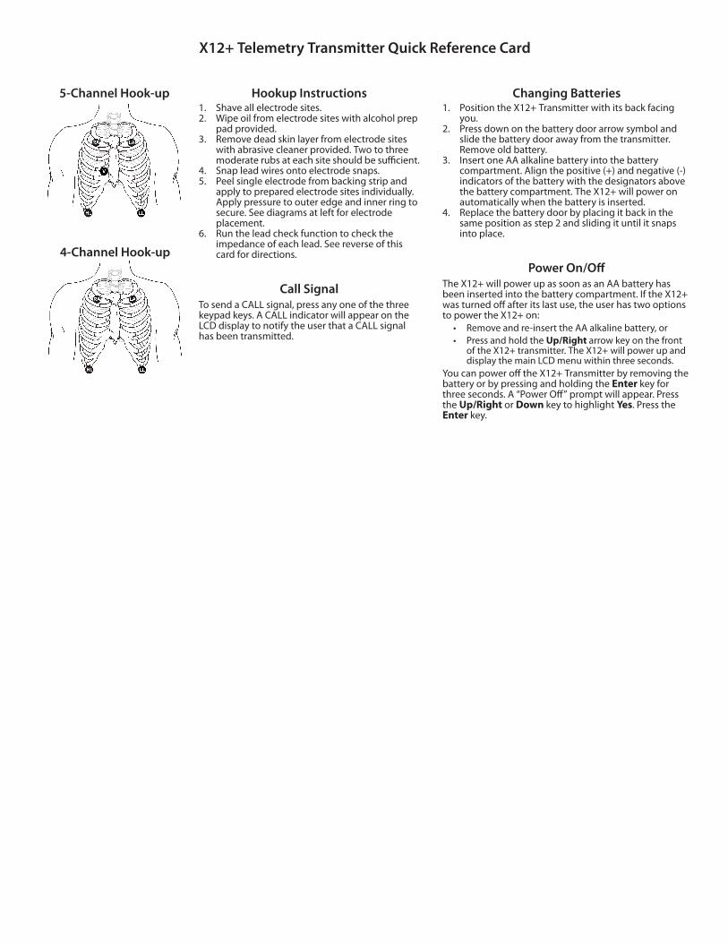
5-Channel Hook-up
4-Channel Hook-up
Hookup Instructions1. Shave all electrode sites.2. Wipe oil from electrode sites with alcohol prep
pad provided. 3. Remove dead skin layer from electrode sites
with abrasive cleaner provided. Two to three moderate rubs at each site should be su cient.
4. Snap lead wires onto electrode snaps.5. Peel single electrode from backing strip and
apply to prepared electrode sites individually. Apply pressure to outer edge and inner ring to secure. See diagrams at left for electrode placement.
6. Run the lead check function to check the impedance of each lead. See reverse of this card for directions.
Call SignalTo send a CALL signal, press any one of the three keypad keys. A CALL indicator will appear on the LCD display to notify the user that a CALL signal has been transmitted.
Changing Batteries1. Position the X12+ Transmitter with its back facing
you.2. Press down on the battery door arrow symbol and
slide the battery door away from the transmitter. Remove old battery.
3. Insert one AA alkaline battery into the battery compartment. Align the positive (+) and negative (-) indicators of the battery with the designators above the battery compartment. The X12+ will power on automatically when the battery is inserted.
4. Replace the battery door by placing it back in the same position as step 2 and sliding it until it snaps into place.
Power On/OThe X12+ will power up as soon as an AA battery has been inserted into the battery compartment. If the X12+ was turned after its last use, the user has two options to power the X12+ on:
• Remove and re-insert the AA alkaline battery, or• Press and hold the Up/Right arrow key on the front
of the X12+ transmitter. The X12+ will power up and display the main LCD menu within three seconds.
You can powe the X12+ Transmitter by removing the battery or by pressing and holding the Enter key for three seconds. A “Power O ” prompt will appear. Press the Up/Right or Down key to highlight Yes. Press the Enter key.
X12+ Telemetry Transmitter Quick Reference Card

Lead Check1. Select the Menu by pressing the Up/Right button continuously
for several seconds. “Lead Check” will appear.2. From the Menu, select Lead Check by pressing the Enter key.3. A graph depicting the impedance measured at the Right Arm
(RA), Left Arm (LA), Left Leg (LL) and optional V leads is displayed from left to right in vertical columns on the screen. The higher the bar, the better the contact is between the skin and the electrode.
4. A full-bar graph means optimal high quality and good electrode contact. For good quality transmissions, the bars should reach or exceed the horizontal line on the display. A low-bar graph means poor quality and high electrode impedance. The skin preparation should be checked for improvement and, if necessary, the electrode(s) should be replaced.
5. Once acceptable impedance levels are ver ed, press any of the three keys to return to the Lead Check menu.
6. Press the Down key to scroll to Done. Press the Enter key.
Lead FailureA lead failure is displayed as a lead designator on the LCD display. If the patient cable is not attached, the LCD will display all leads as disconnected.
Battery Voltage IndicatorThe X12+ is powered with a single AA alkaline battery that requires a minimum of 1.0 volts to operate. When the battery contains su cient voltage, the main menu displays an image of a battery in the upper right corner showing the current battery voltage in increments of 100%, 75%, 50%, and 25%. If a battery with unknown voltage is inserted and the LCD menu does not appear, insert a new battery.
When the battery indicator shows a voltage of 25%, discard the battery and insert a new battery into the battery compartment.
REF: 70-00256-01 Rev C1
Attaching Patient CableThe Patient Cable consists of a connector block, main cable and four
ve leadwires connected to the main cable. Each leadwire terminates in a snap connector. The leadwires are positioned on the main cable to follow the contour of the torso.Insert the connector block into the input connector on the side of the transmitter, making sure that it is parallel to the transmitter input connector.
Reorder Information (www.mortara.com)
Part No. Description
000310-001 Quik-Trace multipurpose electrodes (30/pouch)
036817-013 Transmitter lead set, 4-wire, AHA
036817-014 Transmitter lead set, 4-wire, IEC
036817-003 Transmitter lead set, 5-wire, AHA
036817-004 Transmitter lead set, 5-wire, IEC
042174-001 Pouch and belt for X12+ Transmitter
Mortara Instrument, Inc.7865 North 86th Street, Milwaukee, WI 53224 U.S.A.Tel: 1.800.231.7437 • Fax: 1.414.354.4760Website: www.mortara.comTechnical Support:Tel: 1.888.667.8272Email: [email protected]
Copyright©2014 Mortara Instrument, Inc. All Rights Reserved.