ybm 1200 manual
TRANSCRIPT
8/2/2019 YBM 1200 Manual
http://slidepdf.com/reader/full/ybm-1200-manual 1/31
Yasing YBM-1200 Bluetooth Module Manual
1
Yasing Technology Corp.
YBM-1200
Class 2
Bluetooth Module
Yasing Technology Corp.
(886) 3 5750500
(886) 3 5735512
www.yasingtech.com Version: 0304 V1.4
8/2/2019 YBM 1200 Manual
http://slidepdf.com/reader/full/ybm-1200-manual 2/31
Yasing YBM-1200 Bluetooth Module Manual
2
Tab le o f con t en ts
Selection Guide..................................................................................................................... 3
Overview................................................................................................................................. 4
Features...................................................................................................................................4
Applications............................................................................................................................ 4
Specifications ........................................................................................................................ 5
Block Diagram....................................................................................................................... 6
PCB Footprint ........................................................................................................................ 7
PIN Assignment .................................................................................................................... 8
PIO........................................................................................................................................... 10
External RC Circuit ............................................................................................................ 12
UART Interface.................................................................................................................... 13
USB Interface ...................................................................................................................... 15
PCM Interface...................................................................................................................... 18
Serial Peripheral Interface ............................................................................................. 22
Serial Port Profile Applications......................................................................................24
Acronyms and Definitions............................................................................................... 29
Document References...................................................................................................... 30
Appendix ............................................................................................................................... 30
Revision History.................................................................................................................. 30
8/2/2019 YBM 1200 Manual
http://slidepdf.com/reader/full/ybm-1200-manual 3/31
Yasing YBM-1200 Bluetooth Module Manual
3
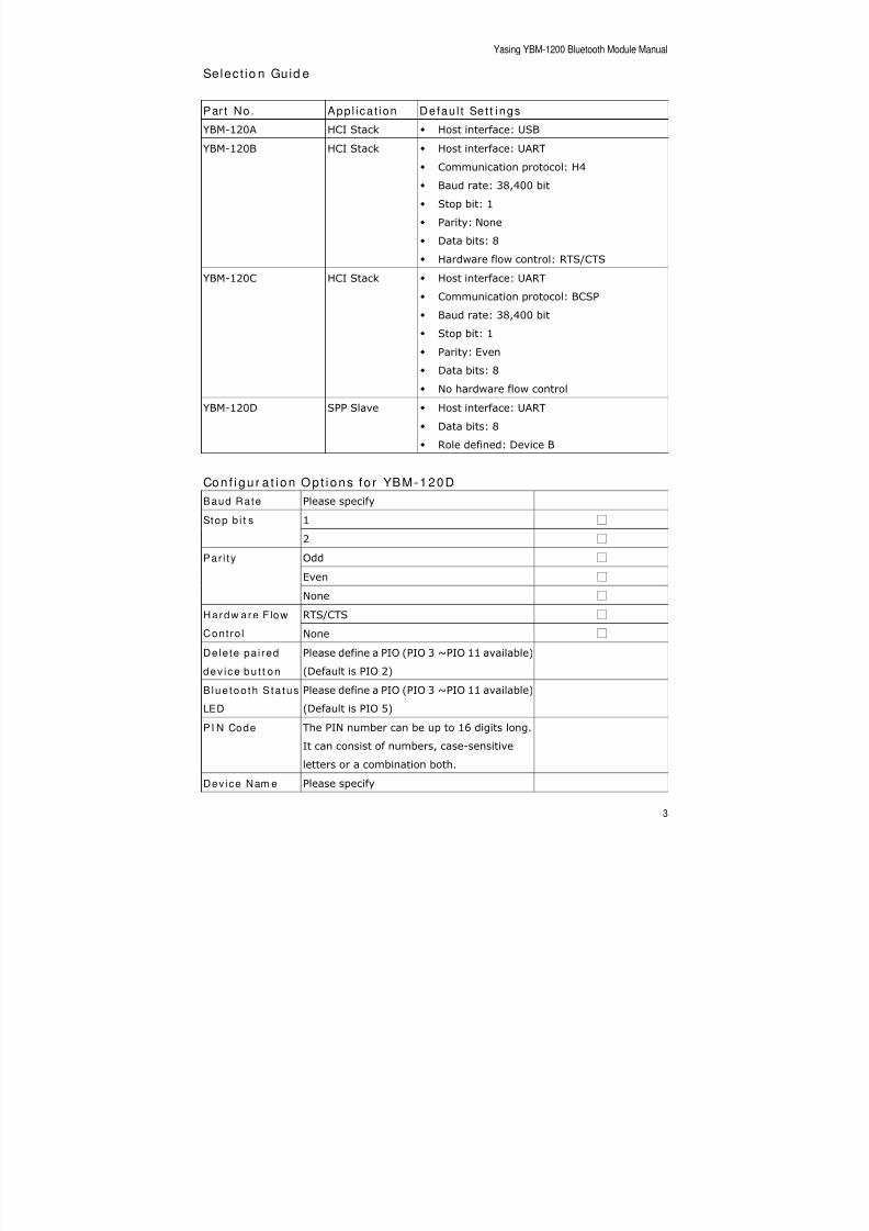
Select io n Guid e
Par t No. App l i ca t ion Defau l t Se t t ings
YBM-120A HCI Stack Host interface: USB
YBM-120B HCI Stack
Host interface: UART Communication protocol: H4
Baud rate: 38,400 bit
Stop bit: 1
Parity: None
Data bits: 8
Hardware flow control: RTS/CTS
YBM-120C HCI Stack Host interface: UART
Communication protocol: BCSP
Baud rate: 38,400 bit
Stop bit: 1
Parity: Even
Data bits: 8
No hardware flow control
YBM-120D SPP Slave Host interface: UART
Data bits: 8
Role defined: Device B
Con f igu r a t i on Op t ions fo r YBM-120D
Baud Rate Please specify
1 Stop b i t s
2
Odd
Even
Par i ty
None
RTS/CTS Hardw are F low
Contro l None
Dele te pa i red
dev ice bu t t on
Please define a PIO (PIO 3 ~PIO 11 available)
(Default is PIO 2)
Blue too th S ta tus
LED
Please define a PIO (PIO 3 ~PIO 11 available)
(Default is PIO 5)
PI N Code The PIN number can be up to 16 digits long.
It can consist of numbers, case-sensitive
letters or a combination both.
Device Nam e Please specify
8/2/2019 YBM 1200 Manual
http://slidepdf.com/reader/full/ybm-1200-manual 4/31
Yasing YBM-1200 Bluetooth Module Manual
4
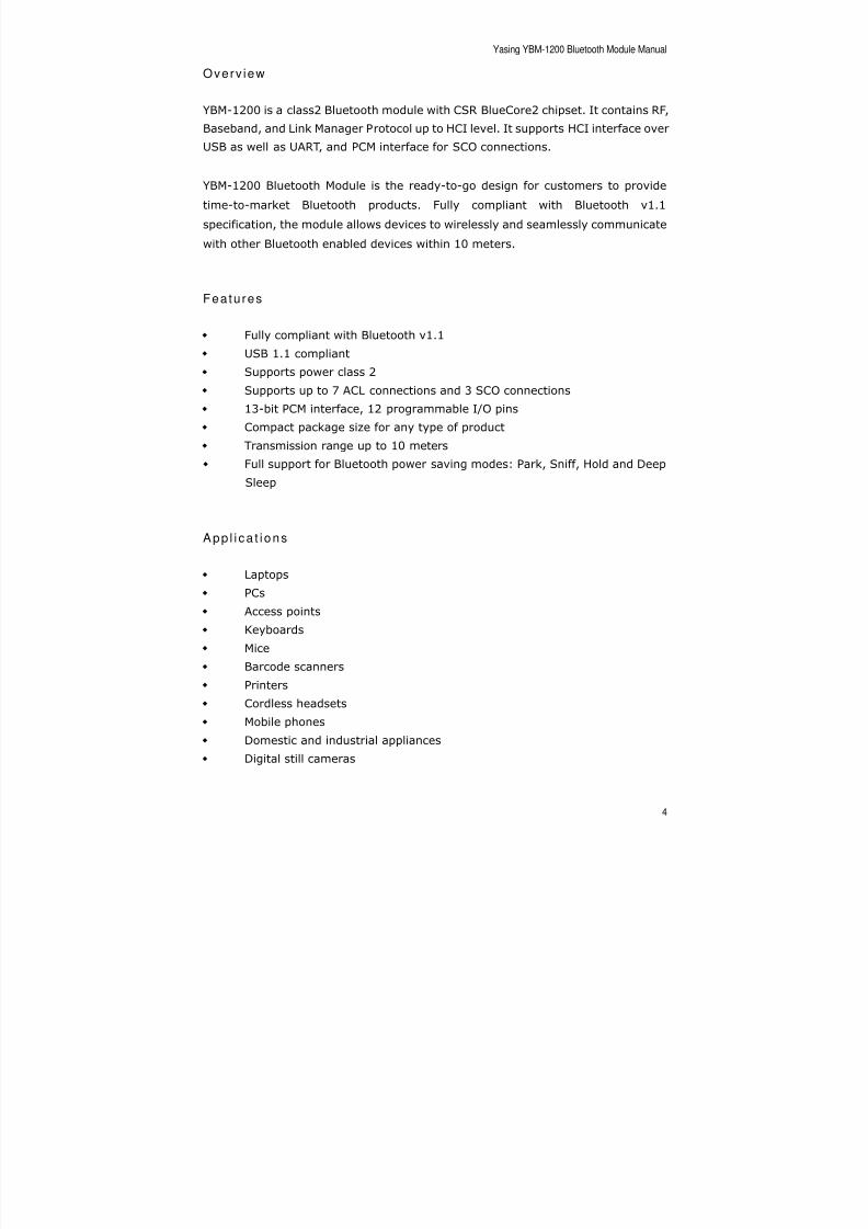
Overv iew
YBM-1200 is a class2 Bluetooth module with CSR BlueCore2 chipset. It contains RF,
Baseband, and Link Manager Protocol up to HCI level. It supports HCI interface over
USB as well as UART, and PCM interface for SCO connections.
YBM-1200 Bluetooth Module is the ready-to-go design for customers to provide
time-to-market Bluetooth products. Fully compliant with Bluetooth v1.1
specification, the module allows devices to wirelessly and seamlessly communicate
with other Bluetooth enabled devices within 10 meters.
Features
Fully compliant with Bluetooth v1.1
USB 1.1 compliant
Supports power class 2
Supports up to 7 ACL connections and 3 SCO connections
13-bit PCM interface, 12 programmable I/O pins
Compact package size for any type of product
Transmission range up to 10 meters
Full support for Bluetooth power saving modes: Park, Sniff, Hold and Deep
Sleep
App l i ca t i ons
Laptops
PCs
Access points
Keyboards
Mice
Barcode scanners
Printers
Cordless headsets
Mobile phones
Domestic and industrial appliances
Digital still cameras
8/2/2019 YBM 1200 Manual
http://slidepdf.com/reader/full/ybm-1200-manual 5/31
Yasing YBM-1200 Bluetooth Module Manual
5
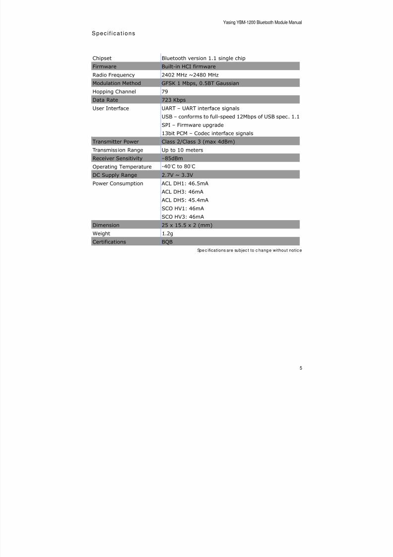
Spec i f i ca t ions
Chipset Bluetooth version 1.1 single chip
Firmware Built-in HCI firmwareRadio Frequency 2402 MHz ~2480 MHz
Modulation Method GFSK 1 Mbps, 0.5BT Gaussian
Hopping Channel 79
Data Rate 723 Kbps
User Interface UART – UART interface signals
USB – conforms to full-speed 12Mbps of USB spec. 1.1
SPI – Firmware upgrade
13bit PCM – Codec interface signals
Transmitter Power Class 2/Class 3 (max 4dBm)
Transmission Range Up to 10 meters
Receiver Sensitivity –85dBm
Operating Temperature -40°C to 80°C
DC Supply Range 2.7V ~ 3.3V
Power Consumption ACL DH1: 46.5mA
ACL DH3: 46mA
ACL DH5: 45.4mA
SCO HV1: 46mA
SCO HV3: 46mA
Dimension 25 x 15.5 x 2 (mm)
Weight 1.2g
Certifications BQB
Spe c ifications are subjec t to c hang e without notic e
8/2/2019 YBM 1200 Manual
http://slidepdf.com/reader/full/ybm-1200-manual 6/31
Yasing YBM-1200 Bluetooth Module Manual
6
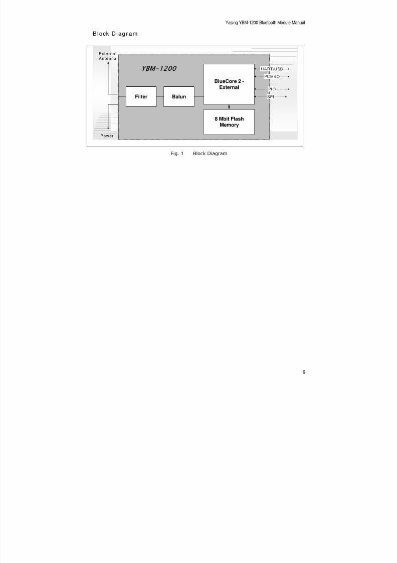
Block D iagr am
Fig. 1 Block Diagram
Filter Balun
BlueCore 2 -External
8 Mbit FlashMemory
UART/USB
PCM/IO
PIO
SPI
Externa l
Antenna
YBM-1200
Power
8/2/2019 YBM 1200 Manual
http://slidepdf.com/reader/full/ybm-1200-manual 7/31
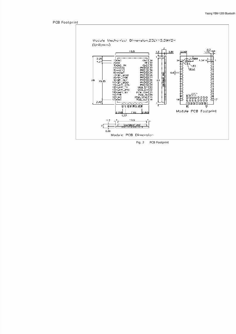
PCB Foot pr in t
Fig. 2 PCB Footprint
8/2/2019 YBM 1200 Manual
http://slidepdf.com/reader/full/ybm-1200-manual 8/31
Yasing YBM-1200 Bluetooth Module Manual
8
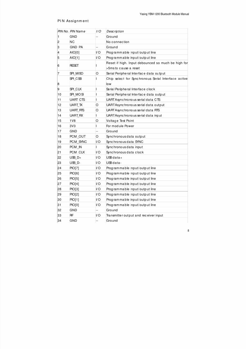
PI N Assignm en t
PIN No. PIN Nam e I/ O Desc ription
1 GND -- Ground
2 NC No c onnec tion3 GND_PA -- Ground
4 AIO[0] I/ O Prog ramm able input/ outp ut line
5 AIO[1] I/ O Prog ramm able input/ outp ut line
6 RESET IReset if high. Input debounced so much be high for
>5ms to c ause a reset
7 SPI_MISO O Serial Periphe ral Inte rfac e da ta outp ut
8
SPI_CSB I Chip selec t for Sync hronous Seria l Inte rfac e ac tive
low
9 SPI_CLK I Seria l Peripheral Interfac e c loc k
10 SPI_MO SI I Serial Periphe ral Inte rfac e da ta outp ut
11 UART_CTS I UART Asynchrono us serial da ta CTS
12 UART_TX O UART Async hrono us serial da ta output
13 UART_RTS O UART Asynchrono us serial da ta RTS
14 UART_RX I UART Async hrono us serial da ta input
15 1V8 O Voltage Test Point
16 3V3 I For mod ule Power
17 GND -- Ground
18 PCM_OUT O Synchronous da ta outp ut
19 PCM_SYNC I/O Sync hronous da ta SYNC
20 PCM _IN I Sync hrono us da ta input
21 PCM_CLK I/ O Sync hronous da ta c lock
22 USB_D+ I/O USB da ta+
23 USB_D- I/O USB da ta-
24 PIO[7] I/ O Prog ram ma ble input/ outp ut line
25 PIO[6] I/ O Prog ram ma ble input/ outp ut line
26 PIO[5] I/ O Prog ram ma ble input/ outp ut line
27 PIO[4] I/ O Prog ram ma ble input/ outp ut line
28 PIO[3] I/ O Prog ram ma ble input/ outp ut line
29 PIO[2] I/ O Prog ram ma ble input/ outp ut line
30 PIO[1] I/ O Prog ram ma ble input/ outp ut line
31 PIO[0] I/ O Prog ram ma ble input/ outp ut line
32 GND -- Ground
33 RF I/ O Transmitte r output and rec eiver input34 GND -- Ground

8/2/2019 YBM 1200 Manual
http://slidepdf.com/reader/full/ybm-1200-manual 9/31
Yasing YBM-1200 Bluetooth Module Manual
9
PIN No. PIN Nam e I/ O Desc ription
35 PIO[8] I/ O Prog ram ma ble input/ outp ut line
36 PIO[9] I/ O Prog ram ma ble input/ outp ut line
37 PIO[10] I/ O Prog ramm able input/ outp ut line
38 PIO[11] I/ O Prog ramm able input/ outp ut line39 GND -- Ground
40 GND -- Ground
41 GND -- Ground
42 GND -- Ground
8/2/2019 YBM 1200 Manual
http://slidepdf.com/reader/full/ybm-1200-manual 10/31
Yasing YBM-1200 Bluetooth Module Manual
10
PI O
The Parallel Input Output (PIO) is a general-purpose input/output interface to
YBM-1200 Bluetooth module. The port consists of 12 programmable, bi-directional
input/output lines. Programmable input/output lines can be assessed either via anembedded application running on YBM-1200 Bluetooth module, or via private
channel or manufacturer-specific HCI commands.
PI O[ 0 ] / RXEN
This is a multifunction terminal. Its function is selected by setting the Persistent
Store Key PSKEY_TXRX_PIO_CONTROL (0x209). It can be used as a programmable
I/O, however it will normally be used to control the radio front-end receive switch.
PI O[ 1 ] / TXEN
This is a multifunction terminal. Its function is selected by setting the Persistent
Store Key PSKEY_TXRX_PIO_CONTROL (0x209). It can be used as a programmable
I/O, however it will normally be used to control the radio front-end receive switch.
Refer to CSR documentation for BlueCore2-External software.
PI O[ 2 ] / U SB _ PU LL_ U P
This is a multifunction terminal. On UART versions of YBM-1200, this terminal is a
programmable I/O. On USB versions, it can drive a pull-up resistor on USB_D+.
PI O[ 3 ] / U SB _ WA KE_ U P
This is a multifunction terminal. On UART versions of YBM-1200, this terminal is a
programmable I/O. On USB versions, its function is selected by setting thePersistent Store Key PSKEY_USB_PIO_WAKEUP (0x2cf) either as a programmable
I/O or as a USB_WAKE_UP function.
PI O[ 4 ] / USB_ ON
This is a multifunction terminal. On UART versions of YBM-1200, this terminal is a
programmable I/O. On USB versions, the USB_ON function is also selectable.
8/2/2019 YBM 1200 Manual
http://slidepdf.com/reader/full/ybm-1200-manual 11/31
Yasing YBM-1200 Bluetooth Module Manual
11
PI O [ 5 ] / USB_DETACH
This is a multifunction terminal. On UART versions of YBM-1200, this terminal is a
programmable I/O. On USB versions, the USB_DETACH function is also selectable.
PI O[ 6 ] / CLK _ REQ
This is a multifunction terminal. The function is determined by Persistent Store Keys.
Using PSKEY_CLOCK_REQUEST_ENABLE, (0x246) this terminal can be configured
to be low when YBM-1200 is in deep sleep and high when a clock is required. The
clock must be supplied within 4ms of the rising edge of PIO[6] to avoid losing timing
accuracy in certain Bluetooth operating modes.
P I O [ 7 ]
Programmable I/O terminal.
P I O [ 8 ]
Programmable I/O terminal.
P I O [ 9 ]
Programmable I/O terminal.
P I O [ 1 0 ]
Programmable I/O terminal.
P I O [ 1 1 ]Programmable I/O terminal.
8/2/2019 YBM 1200 Manual
http://slidepdf.com/reader/full/ybm-1200-manual 12/31
Yasing YBM-1200 Bluetooth Module Manual
12
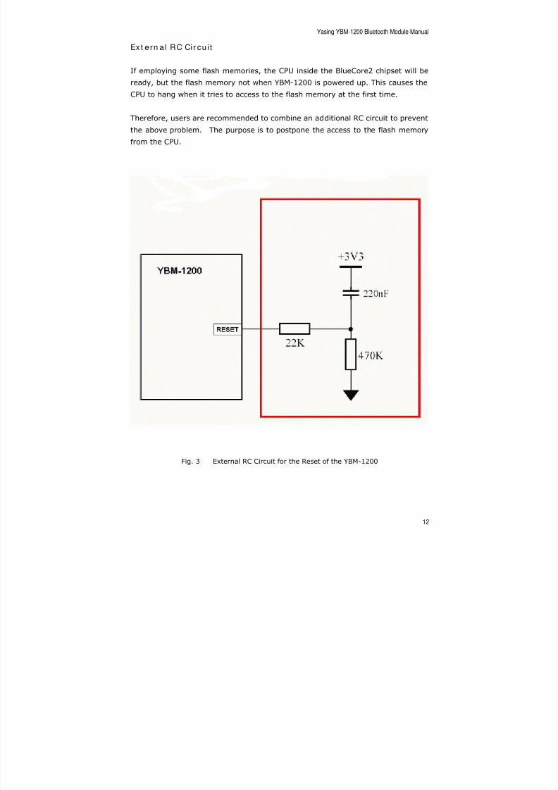
Ext ern a l RC Cir cu i t
If employing some flash memories, the CPU inside the BlueCore2 chipset will be
ready, but the flash memory not when YBM-1200 is powered up. This causes the
CPU to hang when it tries to access to the flash memory at the first time.
Therefore, users are recommended to combine an additional RC circuit to prevent
the above problem. The purpose is to postpone the access to the flash memory
from the CPU.
Fig. 3 External RC Circuit for the Reset of the YBM-1200
8/2/2019 YBM 1200 Manual
http://slidepdf.com/reader/full/ybm-1200-manual 13/31
Yasing YBM-1200 Bluetooth Module Manual
13
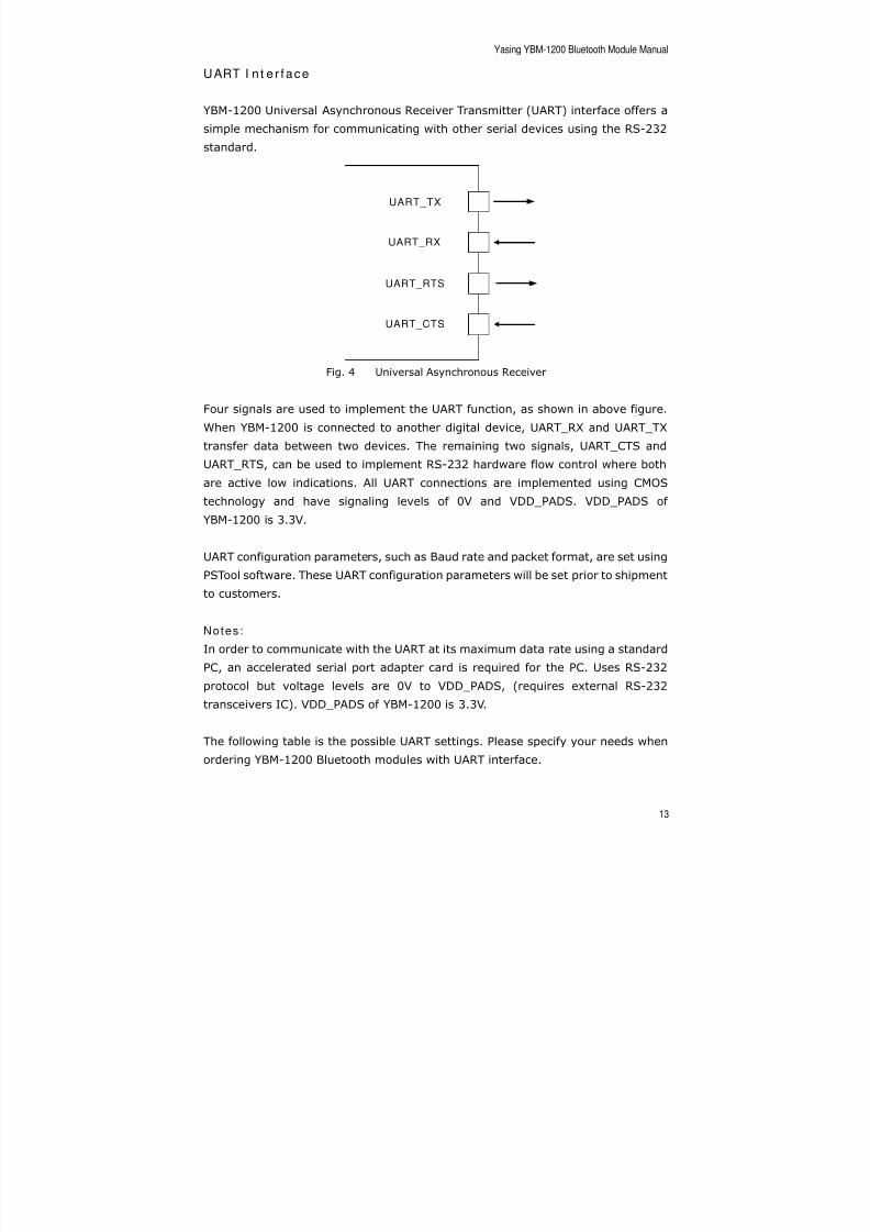
UART I n t e r face
YBM-1200 Universal Asynchronous Receiver Transmitter (UART) interface offers a
simple mechanism for communicating with other serial devices using the RS-232
standard.
Fig. 4 Universal Asynchronous Receiver
Four signals are used to implement the UART function, as shown in above figure.
When YBM-1200 is connected to another digital device, UART_RX and UART_TX
transfer data between two devices. The remaining two signals, UART_CTS and
UART_RTS, can be used to implement RS-232 hardware flow control where both
are active low indications. All UART connections are implemented using CMOS
technology and have signaling levels of 0V and VDD_PADS. VDD_PADS of
YBM-1200 is 3.3V.
UART configuration parameters, such as Baud rate and packet format, are set using
PSTool software. These UART configuration parameters will be set prior to shipment
to customers.
Notes :
In order to communicate with the UART at its maximum data rate using a standard
PC, an accelerated serial port adapter card is required for the PC. Uses RS-232
protocol but voltage levels are 0V to VDD_PADS, (requires external RS-232
transceivers IC). VDD_PADS of YBM-1200 is 3.3V.
The following table is the possible UART settings. Please specify your needs when
ordering YBM-1200 Bluetooth modules with UART interface.
UART_TX
UART_RX
UART_RTS
UART_CTS

8/2/2019 YBM 1200 Manual
http://slidepdf.com/reader/full/ybm-1200-manual 14/31
Yasing YBM-1200 Bluetooth Module Manual
14
Param eter s Poss ib le Va lues
Minimum 1200 Baud (≤2% Error)Baud Rate
Maximum 1.5M Baud (≤1% Error)Hardware Flow Control RTS/CTS or None
Parity Odd, Even or None
Number of Stop Bits 1 or 2
Bits per channel 8
8/2/2019 YBM 1200 Manual
http://slidepdf.com/reader/full/ybm-1200-manual 15/31
Yasing YBM-1200 Bluetooth Module Manual
15
USB I n t e r face
YBM-1200 contains a full-speed (12Mbits/s) USB interface. It is compliant with USB
1.1 specification. YBM-1200 operates as a USB peripheral, responding to requests
from a master host controller such as PC. Both the Open Host Control Interface(OHCI) and the Universal Host Control (UHCI) are supported. The set of USB
endpoints implemented behave as specified in the USB section of the Bluetooth
specification v1.1, part H2.
Pow er Supp l y
The minimum output high voltage for USB data lines is 2.8V. To safely meet the USB
specification, the voltage on terminals must be an absolute minimum of 3.1V.
Yasing recommends 3.3V for optimal USB signal quality.
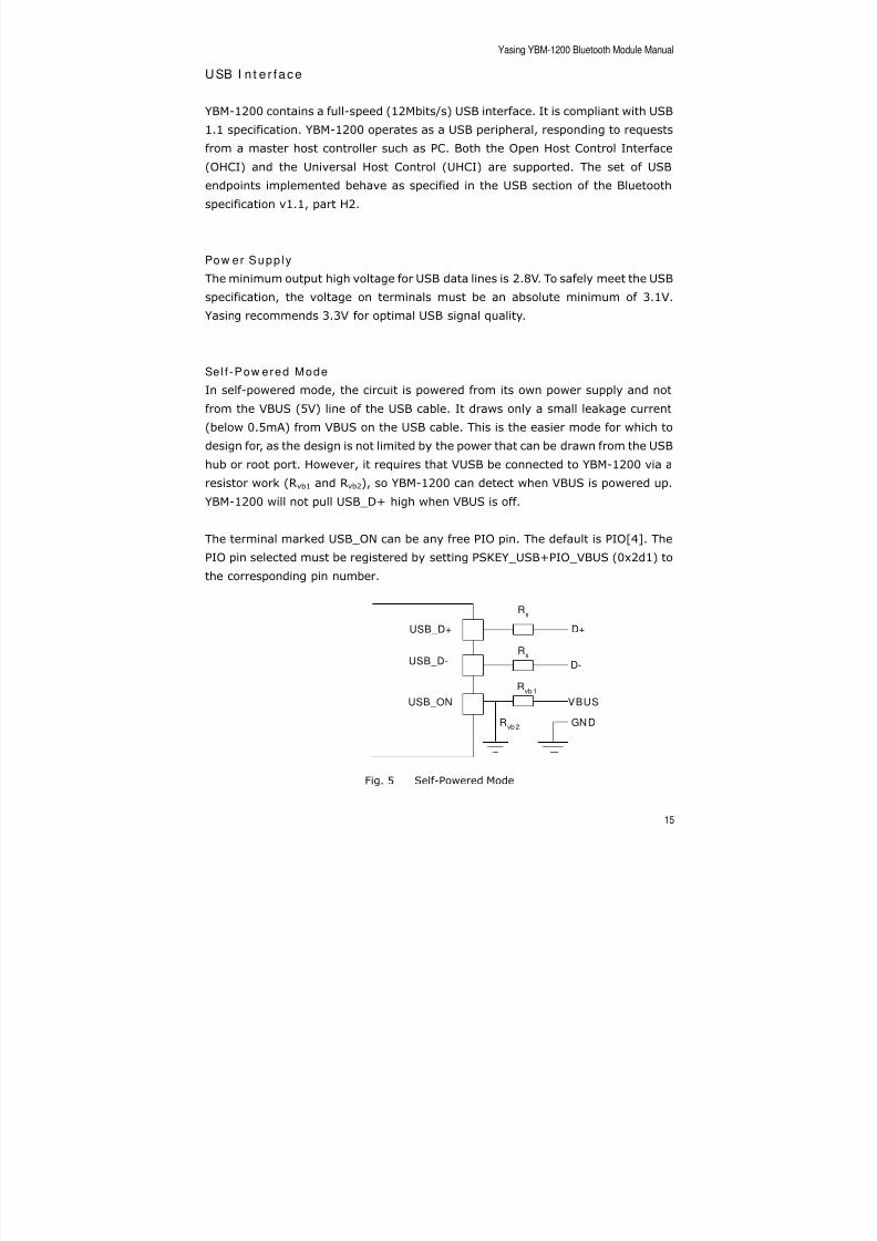
Sel f -Pow ered Mode
In self-powered mode, the circuit is powered from its own power supply and not
from the VBUS (5V) line of the USB cable. It draws only a small leakage current
(below 0.5mA) from VBUS on the USB cable. This is the easier mode for which to
design for, as the design is not limited by the power that can be drawn from the USB
hub or root port. However, it requires that VUSB be connected to YBM-1200 via a
resistor work (Rvb1 and Rvb2), so YBM-1200 can detect when VBUS is powered up.
YBM-1200 will not pull USB_D+ high when VBUS is off.
The terminal marked USB_ON can be any free PIO pin. The default is PIO[4]. The
PIO pin selected must be registered by setting PSKEY_USB+PIO_VBUS (0x2d1) to
the corresponding pin number.
Fig. 5 Self-Powered Mode
USB_D+
USB_D-
USB_ON
D+
D-
VBUS
Rs
Rs
Rvb 1
Rvb 2
GND
8/2/2019 YBM 1200 Manual
http://slidepdf.com/reader/full/ybm-1200-manual 16/31
Yasing YBM-1200 Bluetooth Module Manual
16
Bus-Powered Mode
In bus-powered mode, the application circuit draws its current from the 5V VBUS
supply on the USB cable. YBM-1200 negotiates with the PC during the USB
enumeration stage about power consumption. The 5V VBUS line emerging from a
PC is often electrically noisy. As well as regulation down to 3.3V and 1.8V,applications should include careful filtering of the 5V line to attenuate noise that is
above the voltage regulator’s bandwidth. Excessive noise on the 1.8V supply to the
analogue supply pins of YBM-1200 will result in reduced receive sensitivity and a
distorted transmit signal.
Detach an d W AKE_UP Signal ing
YBM-1200 provides out-of-band signaling to a host controller by using the
dedicated control lines called “USB_DETACH” and “USB_WAKE_UP”. These are
outside the USB specification (no wires exist for them inside the USB cable), but
can be useful when embedding YBM-1200 into a circuit where no external USB is
visible to the user. Both control lines are shared with PIO pins and can be assigned
to any PIO pin by setting the Persistent Store Keys PSKEY_USB_PIO_DETACH
(0x2ce) and PSKEY_USB_PIO_WAKEUP (0x2cf) to the selected PIO number.
USB_DETACH, is an input which, when asserted high, causes YBM-1200 to put
USB_D- and USB_D+ in a high-impedance state and to 1.5KΩ pull-up resistor on
USB_D+. This detaches the device from the bus and is logically equivalent to
unplugging the device. When USB-DETACH is taken low, YBM-1200 will connect
back to USB and await enumeration by the USB host.
USB_WAKE_UP, is an active high output (used only when USB_DETACH is active) to
wake up the host and allow USB communication to recommence. It replaces the
function of the software USB_WAKE_UP message (which runs over the USB cable
proper), and cannot be sent while YBM-1200 is effectively disconnected from thebus.
USB Dr iv er
A USB Bluetooth device driver is required to provide a software interface between
YBM-1200 and Bluetooth applications running on the host.
8/2/2019 YBM 1200 Manual
http://slidepdf.com/reader/full/ybm-1200-manual 17/31
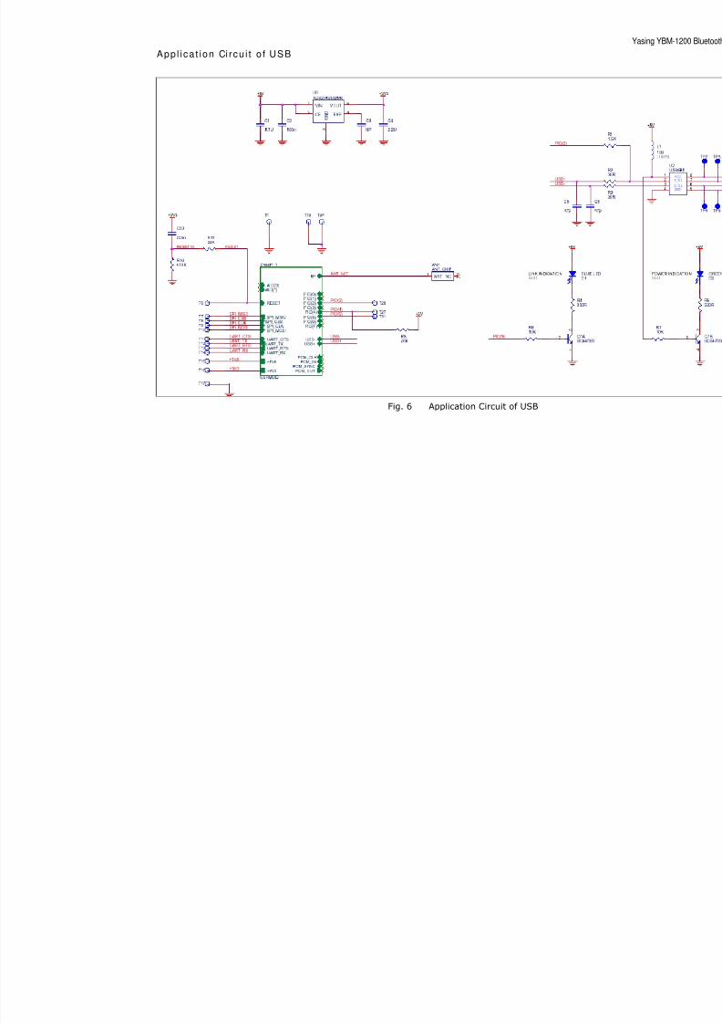
App l i ca t ion Ci rcu i t o f USB
Fig. 6 Application Circuit of USB
8/2/2019 YBM 1200 Manual
http://slidepdf.com/reader/full/ybm-1200-manual 18/31
Yasing YBM-1200 Bluetooth Module Manual
18
PCM I n t e r face
Pulse Code Modulation (PCM) is the standard method used to digitize human voice
patterns for transmission over digital communication channels. Through the PCM
interface, YBM-1200 has hardware support for continual transmission andreception of PCM data, thus reducing processor overhead for wireless headset
applications. YBM-1200 provides a bi-directional digital audio interface that routes
directly into the Baseband layer of the on-chip firmware. It does not pass through
the HCI protocol layer.
Hardware on YBM-1200 allows the data to be sent to and received from a SCO
connection. Up to three SCO connections can be supported by the PCM interface at
any one time.
YBM-1200 can operate as the PCM interface Maser generating an output clock of
128, 256 or 512KHz. When configured as PCM interfaces slave it can operate with
an input clock up to 2048KHz. YBM-1200 is compatible with a variety of clock
formats, including Long Frame Sync, Short Frame Sync and GCI timing
environments. It supports 13 or 16 bit linear, 8-bit μ-law or A-law compared
sample format at 8ksamples/s and can receive and transmit on any selection of
three of the first four slots following PCM_SYNC. The PCM configuration options are
enabled by setting the Persistent Store Key PSKEY_PCM_CONFIG (0x1b3).
PCM I n te r f ace Maste r / Slave
When configured as the Master of the PCM interface, YBM-1200 generates
PCM_CLK and PCM_SYNC. When configured as the Slave of PCM interface,
YBM-1200 accepts PCM_CLK rates up to 2048KHz.
Long Fram e Sync
Long Frame Sync is the name given to a clocking format that controls the transfer
of PCM data words or samples. In Long Frame Sync, the rising edge of PCM_Sync
indicates the start of the PCM word. When YBM-1200 is configured as PCM Master,
generating PCM_SYNC and PCM_CLK, then PCM_SYNC is 8-bits long. When
YBM-1200 is configured as PCM slave, PCM-SYNC may be from two consecutive
falling edges of PCM_CLK to half the PCM_SYNC rate (i.e., 62.5μs) long.
YBM-1200 samples PCM_IN on the falling edge of PCM_CLK and transmits
8/2/2019 YBM 1200 Manual
http://slidepdf.com/reader/full/ybm-1200-manual 19/31
Yasing YBM-1200 Bluetooth Module Manual
19
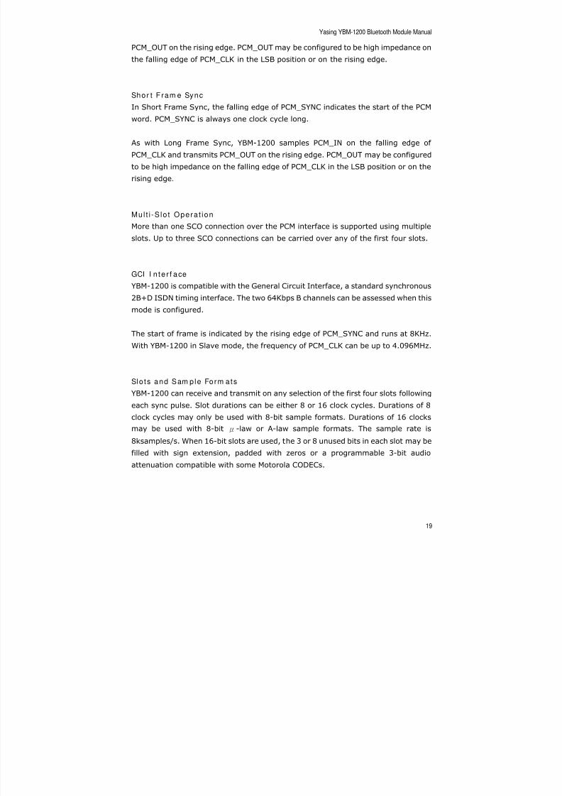
PCM_OUT on the rising edge. PCM_OUT may be configured to be high impedance on
the falling edge of PCM_CLK in the LSB position or on the rising edge.
Shor t Fram e SyncIn Short Frame Sync, the falling edge of PCM_SYNC indicates the start of the PCM
word. PCM_SYNC is always one clock cycle long.
As with Long Frame Sync, YBM-1200 samples PCM_IN on the falling edge of
PCM_CLK and transmits PCM_OUT on the rising edge. PCM_OUT may be configured
to be high impedance on the falling edge of PCM_CLK in the LSB position or on the
rising edge.
Mul t i -S lo t Opera t ion
More than one SCO connection over the PCM interface is supported using multiple
slots. Up to three SCO connections can be carried over any of the first four slots.
GCI I n te r f ace
YBM-1200 is compatible with the General Circuit Interface, a standard synchronous
2B+D ISDN timing interface. The two 64Kbps B channels can be assessed when this
mode is configured.
The start of frame is indicated by the rising edge of PCM_SYNC and runs at 8KHz.
With YBM-1200 in Slave mode, the frequency of PCM_CLK can be up to 4.096MHz.
Slo ts and Sam ple Form ats
YBM-1200 can receive and transmit on any selection of the first four slots followingeach sync pulse. Slot durations can be either 8 or 16 clock cycles. Durations of 8
clock cycles may only be used with 8-bit sample formats. Durations of 16 clocks
may be used with 8-bit μ-law or A-law sample formats. The sample rate is
8ksamples/s. When 16-bit slots are used, the 3 or 8 unused bits in each slot may be
filled with sign extension, padded with zeros or a programmable 3-bit audio
attenuation compatible with some Motorola CODECs.
8/2/2019 YBM 1200 Manual
http://slidepdf.com/reader/full/ybm-1200-manual 20/31
Yasing YBM-1200 Bluetooth Module Manual
20
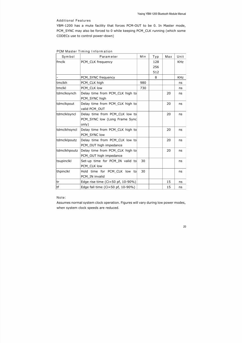
Add i t iona l Fea tures
YBM-1200 has a mute facility that forces PCM-OUT to be 0. In Master mode,
PCM_SYNC may also be forced to 0 while keeping PCM_CLK running (which some
CODECs use to control power-down)
PCM Maste r T im ing I n fo rm a t i on
Sym bo l Param eter Min Typ Max Un i t
fmclk PCM_CLK frequency 128
256
512
KHz
- PCM_SYNC frequency 8 KHz
tmclkh PCM_CLK high 980 ns
tmclkl PCM_CLK low 730 ns
tdmclksynch Delay time from PCM_CLK high to
PCM_SYNC high
20 ns
tdmclkpout Delay time from PCM_CLK high to
valid PCM_OUT
20 ns
tdmclklsyncl Delay time from PCM_CLK low to
PCM_SYNC low (Long Frame Sync
only)
20 ns
tdmclkhsyncl Delay time from PCM_CLK high to
PCM_SYNC low
20 ns
tdmclklpoutz Delay time from PCM_CLK low to
PCM_OUT high impedance
20 ns
tdmclkhpoutz Delay time from PCM_CLK high to
PCM_OUT high impedance
20 ns
tsupinclkl Set-up time for PCM_IN valid to
PCM_CLK low
30 ns
thpinclkl Hold time for PCM_CLK low to
PCM_IN invalid
30 ns
tr Edge rise time (Ci=50 pf, 10-90%) 15 ns
tf Edge fall time (Ci=50 pf, 10-90%) 15 ns
Note :
Assumes normal system clock operation. Figures will vary during low power modes,
when system clock speeds are reduced.
8/2/2019 YBM 1200 Manual
http://slidepdf.com/reader/full/ybm-1200-manual 21/31
Yasing YBM-1200 Bluetooth Module Manual
21
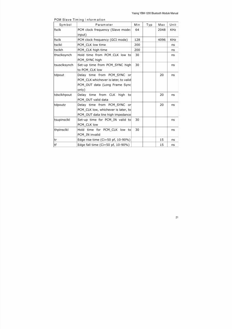
PCM Slave Tim ing I n fo rm a t i on
Sym bo l Param eter Min Typ Max Un i t
fsclk PCM clock frequency (Slave mode:
input)
64 2048 KHz
fsclk PCM clock frequency (GCI mode) 128 4096 KHztsclkl PCM_CLK low time 200 ns
tsclkh PCM_CLK high time 200 ns
thsclksynch Hold time from PCM_CLK low to
PCM_SYNC high
30 ns
tsusclksynch Set-up time from PCM_SYNC high
to PCM_CLK low
30 ns
tdpout Delay time from PCM_SYNC or
PCM_CLK whichever is later, to validPCM_OUT data (Long Frame Sync
only)
20 ns
tdsclkhpout Delay time from CLK high to
PCM_OUT valid data
20 ns
tdpoutz Delay time from PCM_SYNC or
PCM_CLK low, whichever is later, to
PCM_OUT data line high impedance
20 ns
tsupinsclkl Set-up time for PCM_IN valid to
PCM_CLK low
30 ns
thpinsclkl Hold time for PCM_CLK low to
PCM_IN invalid
30 ns
tr Edge rise time (Ci=50 pf, 10-90%) 15 ns
tf Edge fall time (Ci=50 pf, 10-90%) 15 ns
8/2/2019 YBM 1200 Manual
http://slidepdf.com/reader/full/ybm-1200-manual 22/31
Yasing YBM-1200 Bluetooth Module Manual
22
Ser ia l Pe r iphe ra l I n t e r face
YBM-1200 uses 16-bit address during serial peripheral interface transactions. Such
transactions will occur whether the internal processor is running or is stopped. Data
may be written or read one word at a time or the audio-increment feature may beused to access blocks.
I ns t ruc t i on Cyc le
Before YBM-1200 can be addressed, SPI_CSB must be taken low (SPI_CSB=0).
Data on SPI_MOSI is then clocked into YBM-1200 on the rising edge of the clock line
SPI_CLK.
When reading, YBM-1200 will reply to the Master on MISO (the data being valid on
falling edge of the SPI_CLK). The Master provides the clocking.
Sing le Cycle Operat ion
After a serial peripheral interface transaction completes, the Master toggles
SPI_CLK with SPI_CSB high to initiate a new transaction. SPI_CSB must be high for
at least two SPI_CLK cycles.
Mul t i -S lave Opera t ion
YBM-1200 should not be connected in a multi-slave arrangement by simple parallel
connection of slave MISO lines. When YBM-1200 is deselected (SPI_CSB=1), the
SPI_MISO line does not float. Instead, YBM-1200 outputs 0 if the processor is
running or 1 if it is stopped.
Wr i t i ng to YBM-1200To write to YBM-1200, the 8-bit write command (00000010) is sent first (C[7:0])
followed by a 16-bit address (A[15:0]). After that, 16-bits of data (D[15:0]) are
sent.
A u to - I n c r em e n t Op e r at i o n
Sending a command word and the address of a register every time it is to be read
or written can be a significant overhead, especially when large amounts of data areto be transferred. To overcome this, YBM-1200 offers increased data transfer

8/2/2019 YBM 1200 Manual
http://slidepdf.com/reader/full/ybm-1200-manual 23/31
Yasing YBM-1200 Bluetooth Module Manual
23
efficiency via an auto-increment operation. During operation, YBM-1200
increments the address automatically. Only the data is transmitted or received over
the serial peripheral interface. YBM-1200 keeps the previous command word.
Auto-increment mode is invoked by SPI_CSB low after the last bit of a read or writeoperation, while providing an extra 16 clock cycles. If the previous command was a
write, continuous 16-bit words of data may then be written to the YBM-1200
without the need to send the address or command word. Similarly, if the previous
command was a read, then data may be read. T[15:0] are not returned after the
first read, just D[15:0].
App l i ca t ion Ci rcu i t o f SPI
Fig. 7 Application Circuit of SPI
8/2/2019 YBM 1200 Manual
http://slidepdf.com/reader/full/ybm-1200-manual 24/31
Yasing YBM-1200 Bluetooth Module Manual
24
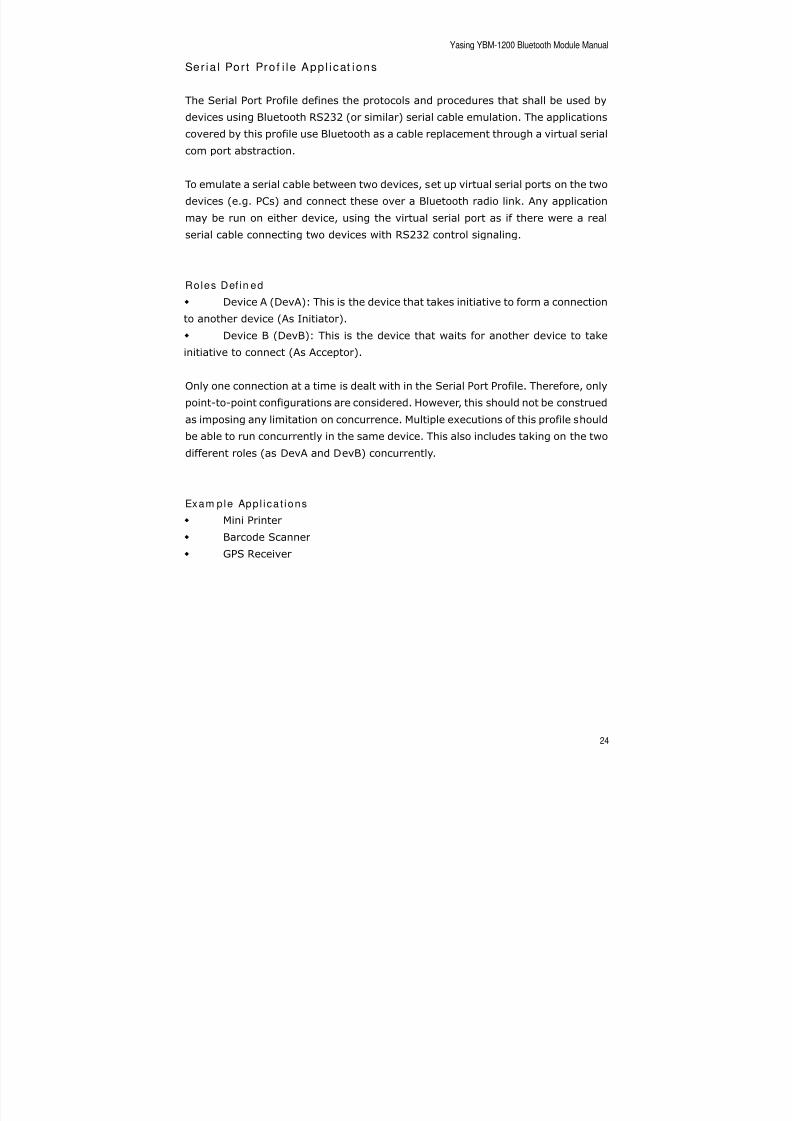
Ser ia l Por t Pro f i le App l icat ions
The Serial Port Profile defines the protocols and procedures that shall be used by
devices using Bluetooth RS232 (or similar) serial cable emulation. The applications
covered by this profile use Bluetooth as a cable replacement through a virtual serialcom port abstraction.
To emulate a serial cable between two devices, set up virtual serial ports on the two
devices (e.g. PCs) and connect these over a Bluetooth radio link. Any application
may be run on either device, using the virtual serial port as if there were a real
serial cable connecting two devices with RS232 control signaling.
Roles Def in ed
Device A (DevA): This is the device that takes initiative to form a connection
to another device (As Initiator).
Device B (DevB): This is the device that waits for another device to take
initiative to connect (As Acceptor).
Only one connection at a time is dealt with in the Serial Port Profile. Therefore, only
point-to-point configurations are considered. However, this should not be construed
as imposing any limitation on concurrence. Multiple executions of this profile should
be able to run concurrently in the same device. This also includes taking on the two
different roles (as DevA and DevB) concurrently.
Exam ple App l i ca t ions
Mini Printer
Barcode Scanner
GPS Receiver

8/2/2019 YBM 1200 Manual
http://slidepdf.com/reader/full/ybm-1200-manual 25/31
Appl i cat io n Ci rcu i t o f SPP-Slave
Fig. 8 Application Circuit of SPP-Slave
8/2/2019 YBM 1200 Manual
http://slidepdf.com/reader/full/ybm-1200-manual 26/31
Yasing YBM-1200 Bluetooth Module Manual
26
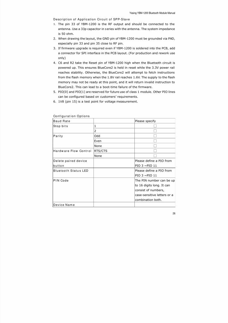
Descr ip t ion o f App l i ca t ion Ci rcu i t o f SPP-Slave
1. The pin 33 of YBM-1200 is the RF output and should be connected to the
antenna. Use a 33p capacitor in series with the antenna. The system impedance
is 50 ohm.
2. When drawing the layout, the GND pin of YBM-1200 must be grounded via PAD,especially pin 33 and pin 35 close to RF pin.
3. If firmware upgrade is required even if YBM-1200 is soldered into the PCB, add
a connector for SPI interface in the PCB layout. (For production and rework use
only)
4. C6 and R2 take the Reset pin of YBM-1200 high when the Bluetooth circuit is
powered up. This ensures BlueCore2 is held in reset while the 3.3V power rail
reaches stability. Otherwise, the BlueCore2 will attempt to fetch instructions
from the flash memory when the 1.8V rail reaches 1.6V. The supply to the flash
memory may not be ready at this point, and it will return invalid instruction to
BlueCore2. This can lead to a boot-time failure of the firmware.
5. PIO[0] and PIO[1] are reserved for future use of class 1 module. Other PIO lines
can be configured based on customers’ requirements.
6. 1V8 (pin 15) is a test point for voltage measurement.
Con f i gu ra t i on Op t i ons
Baud Rat e Please specify
1 Stop b i t s
2
Odd
Even
Par i ty
None
RTS/CTS Hardw are Flow Con t r o l
None
Dele te pa i red dev ice
b u t t o n
Please define a PIO from
PIO 3 ~PIO 11
Blue too t h Sta tu s LED Please define a PIO from
PIO 3 ~PIO 11
PI N Code The PIN number can be up
to 16 digits long. It can
consist of numbers,
case-sensitive letters or a
combination both.
Device Nam e

8/2/2019 YBM 1200 Manual
http://slidepdf.com/reader/full/ybm-1200-manual 27/31
Yasing YBM-1200 Bluetooth Module Manual
27
When streaming data continuously or sending large blocks of data, it is
recommended to use hardware flow control.
Fig. 9 Secure Connection of Bluetooth Serial Port
How to Test a B lue too th M in i Pr i n t e r
In the following section, a PC with a USB Dongle and WIDCOMM BTW software
installed will be taken as the remote Bluetooth device for the mini printer.
1. On your computer, right click the Bluetooth icon on the Windows system tray,
and choose Advanced Conf ig ur a t ion .
2. Select Cl ien t App l i ca t ions .
3. Make sure the Secure Connection of Bluetooth Serial Port is required.
4. Double click the Bluetooth icon on the Windows system tray or on the desktop.
5. From My Bluetooth Places, click Entire Bluetooth Neighborhood in the folder
pane.
6. Right click anywhere except the device items in the right pane and selectSearch from the pop-up menu.
8/2/2019 YBM 1200 Manual
http://slidepdf.com/reader/full/ybm-1200-manual 28/31
Yasing YBM-1200 Bluetooth Module Manual
28
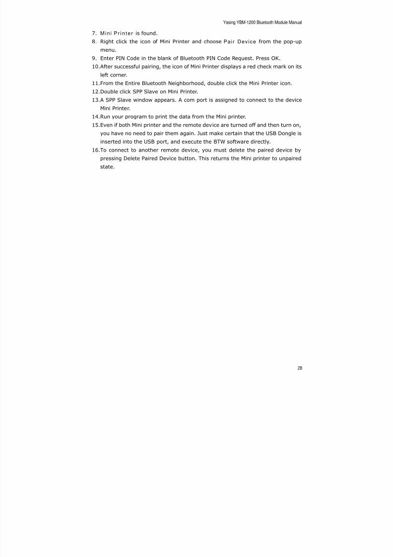
7. Min i P r i n te r is found.
8. Right click the icon of Mini Printer and choose Pair Device from the pop-up
menu.
9. Enter PIN Code in the blank of Bluetooth PIN Code Request. Press OK.
10.After successful pairing, the icon of Mini Printer displays a red check mark on itsleft corner.
11.From the Entire Bluetooth Neighborhood, double click the Mini Printer icon.
12.Double click SPP Slave on Mini Printer.
13.A SPP Slave window appears. A com port is assigned to connect to the device
Mini Printer.
14.Run your program to print the data from the Mini printer.
15.Even if both Mini printer and the remote device are turned off and then turn on,
you have no need to pair them again. Just make certain that the USB Dongle is
inserted into the USB port, and execute the BTW software directly.
16.To connect to another remote device, you must delete the paired device by
pressing Delete Paired Device button. This returns the Mini printer to unpaired
state.
8/2/2019 YBM 1200 Manual
http://slidepdf.com/reader/full/ybm-1200-manual 29/31
Yasing YBM-1200 Bluetooth Module Manual
29
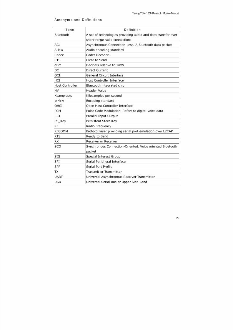
Acronym s and Def in i t i ons
Term De f i n i t i on
Bluetooth A set of technologies providing audio and data transfer over
short-range radio connectionsACL Asynchronous Connection-Less. A Bluetooth data packet
A-law Audio encoding standard
Codec Coder Decoder
CTS Clear to Send
dBm Decibels relative to 1mW
DC Direct Current
GCI General Circuit Interface
HCI Host Controller InterfaceHost Controller Bluetooth integrated chip
HV Header Value
Ksamples/s Kilosamples per second
μ-law Encoding standard
OHCI Open Host Controller Interface
PCM Pulse Code Modulation. Refers to digital voice data
PIO Parallel Input Output
PS_Key Persistent Store KeyRF Radio Frequency
RFCOMM Protocol layer providing serial port emulation over L2CAP
RTS Ready to Send
RX Receiver or Receiver
SCO Synchronous Connection-Oriented. Voice oriented Bluetooth
packet
SIG Special Interest Group
SPI Serial Peripheral InterfaceSPP Serial Port Profile
TX Transmit or Transmitter
UART Universal Asynchronous Receiver Transmitter
USB Universal Serial Bus or Upper Side Band
8/2/2019 YBM 1200 Manual
http://slidepdf.com/reader/full/ybm-1200-manual 30/31
Yasing YBM-1200 Bluetooth Module Manual
30
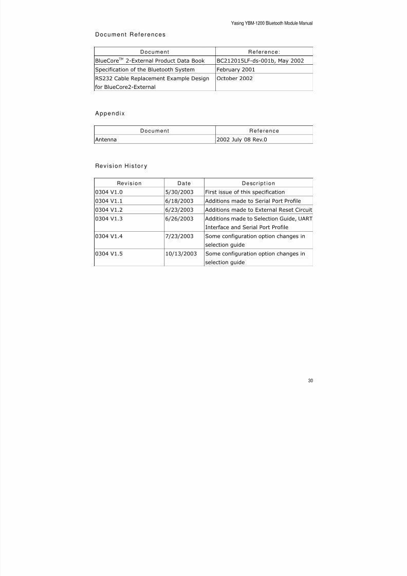
Document Refe rences
Document Reference :
BlueCoreTM 2-External Product Data Book BC212015LF-ds-001b, May 2002
Specification of the Bluetooth System February 2001RS232 Cable Replacement Example Design
for BlueCore2-External
October 2002
Append ix
Document Reference
Antenna 2002 July 08 Rev.0
Rev is ion H is to r y
Revis ion Date Descr ip t ion
0304 V1.0 5/30/2003 First issue of this specification
0304 V1.1 6/18/2003 Additions made to Serial Port Profile
0304 V1.2 6/23/2003 Additions made to External Reset Circuit
0304 V1.3 6/26/2003 Additions made to Selection Guide, UART
Interface and Serial Port Profile
0304 V1.4 7/23/2003 Some configuration option changes in
selection guide
0304 V1.5 10/13/2003 Some configuration option changes in
selection guide

8/2/2019 YBM 1200 Manual
http://slidepdf.com/reader/full/ybm-1200-manual 31/31
Yasing YBM-1200 Bluetooth Module Manual
Bluetooth is a trademark owned by Bluetooth SIG, Inc., U.S.A. and licensed to
Yasing.