year iii computer sci. english 1-st semester -...
TRANSCRIPT

Design with Microprocessors
Year III Computer Sci. English 1-st Semester
Lecture 14: 8086/8088-BASED MULTIPROCESSOR SYSTEMS

8086 in maximum mode (#MX=0)

8288 Command Decode Definition
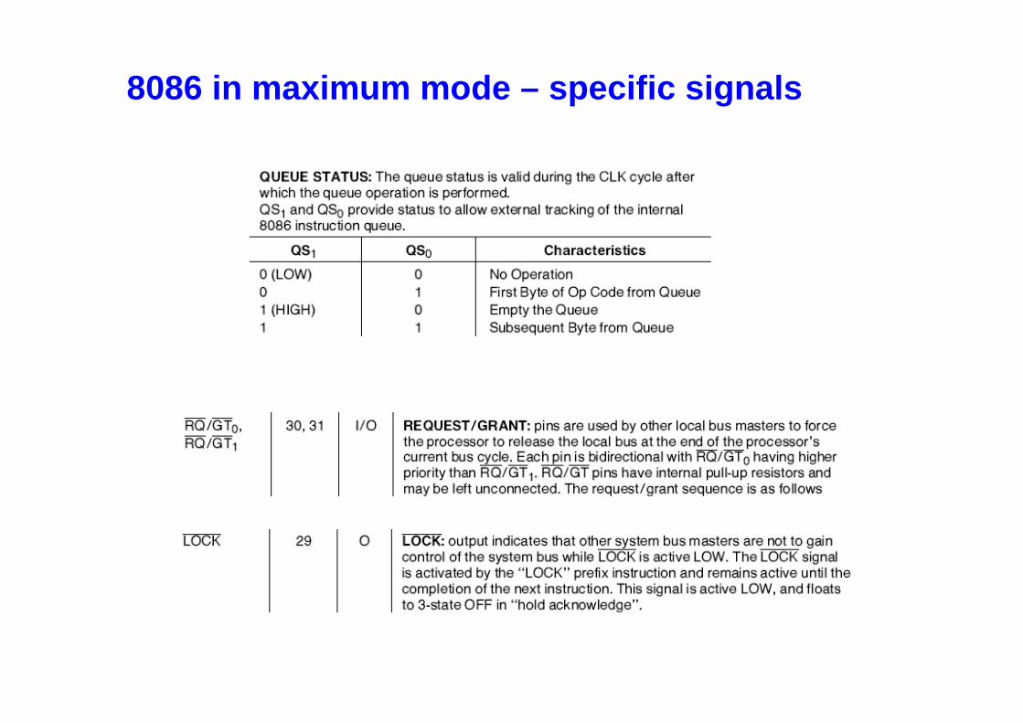
8086 in maximum mode – specific signals
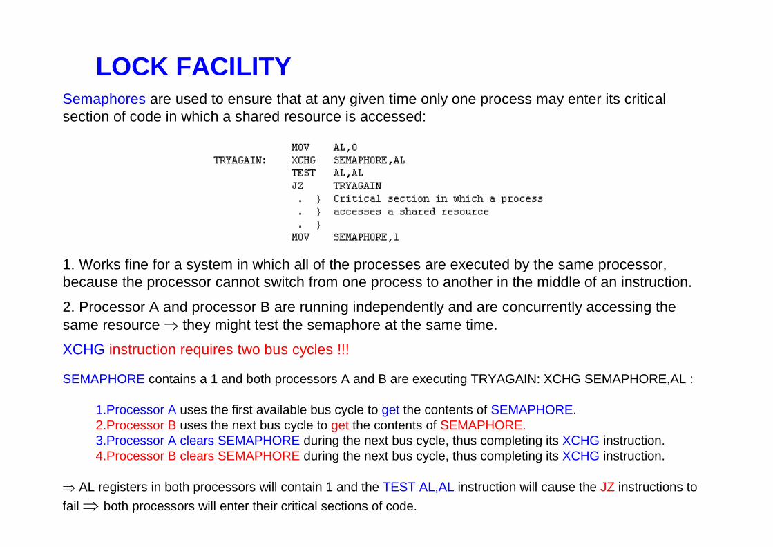
Semaphores are used to ensure that at any given time only one process may enter its critical section of code in which a shared resource is accessed:
1. Works fine for a system in which all of the processes are executed by the same processor, because the processor cannot switch from one process to another in the middle of an instruction.
2. Processor A and processor B are running independently and are concurrently accessing the same resource ⇒ they might test the semaphore at the same time.
XCHG instruction requires two bus cycles !!!
SEMAPHORE contains a 1 and both processors A and B are executing TRYAGAIN: XCHG SEMAPHORE,AL :
1.Processor A uses the first available bus cycle to get the contents of SEMAPHORE. 2.Processor B uses the next bus cycle to get the contents of SEMAPHORE. 3.Processor A clears SEMAPHORE during the next bus cycle, thus completing its XCHG instruction. 4.Processor B clears SEMAPHORE during the next bus cycle, thus completing its XCHG instruction.
⇒ AL registers in both processors will contain 1 and the TEST AL,AL instruction will cause the JZ instructions to
fail ⇒ both processors will enter their critical sections of code.
LOCK FACILITY

⇒ the processor that starts executing its XCHG instruction first (which in this example is processor A) must have exclusive use of the bus until the XCHG instruction is completed ⇒ LOCK prefix:
⇒ maximum mode CPU, activates the \LOCK output pin during the execution of the instruction that follows the prefix. ⇒ \LOCK signal indicates to the bus control logic that no other processors may gain control of the
system bus until the locked instruction is completed:
TRYAGAIN: LOCK XCHG SEMAPHORE,AL
⇒ would ensure that each XCHG will be completed in two consecutive bus cycles.
Physically, in a loosely coupled system each processing module includes a bus arbiter and the bus arbiters are connected together by special control lines in the system bus. One of these lines is a busy line which is active whenever the bus is in use.
If a \LOCK signal is sent to the arbiter controlling the bus, then that arbiter will retain control of the system by holding the busy line active until the \LOCK signal is dropped.Thus, if a processor applies a \LOCK signal throughout the execution of an entire instruction, its arbiter will not relinquish the system bus until the instruction is complete.
LOCK FACILITY

LOCK FACILITYAnother possible application of the bus lock capability:
⇒ fast execution of an instruction which requires several bus cycles.
For example, in a multiprocessor system a block of data can be transferred at a higher speed by using the LOCK prefix as follows:
LOCK REP MOVSB DEST , SRC
During the execution of this instruction the system bus will be reserved for the sole use of the processor executing the instruction.
REP
if CX <> 0 then do following chain instructionCX = CX - 1 go back to check_cx
else exit from REP cycle
MOVSB
ES:[DI] = DS:[SI]
if DF = 0 then SI = SI + 1 DI = DI + 1
else SI = SI - 1 DI = DI - 1

Ref: Microcomputer Systems: The 8086/8088 Family, Liu & Gibson, 1986
Multiprocessor Systems refer to the use of multiple processors that execute instructions simultaneously and communicate using mailboxes and semaphores
Maximum mode of 8086 is designed to implement 3 basic multiprocessor configurations :
1. coprocessor (8087)
2. closely coupled (dedeicated I/O processor:8089)
3. loosely coupled (Multibus)
Coprocessors and closely coupled configurations are similar - both the CPU and the external processor share:
– Memory
– I/O system
– Bus & bus control logic
– Clock generator
8086/8088-BASED MULTIPROCESSING SYSTEMS

Coprocessor Configuration
WAIT instruction ⇒⇒⇒⇒ allows the processor to synchronize itself with external hardware, eg., waiting for 8087 math co-processor.
⇒ When the CPU executes WAIT ⇒⇒⇒⇒ waiting state. ⇒TEST input is asserted (low), the waiting state is completed andexecution will resume.
ESC instruction: ESC opcode , operandopcode : immediate value recognizable to a coprocessor as an instruction opcodeoperand : name of a register or a memory address (in any mode)⇒ When the CPU executes the ESC instruction, the processor accesses the memory operand by placing the address on the address bus. ⇒ If a coprocessor is configured to share the system bus, it willrecognize the ESC instruction and therefore will get the opcode and the operand.

Coprocessor Configuration
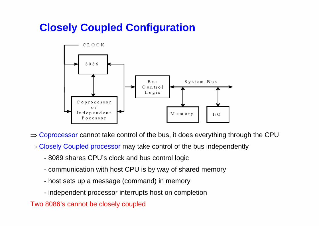
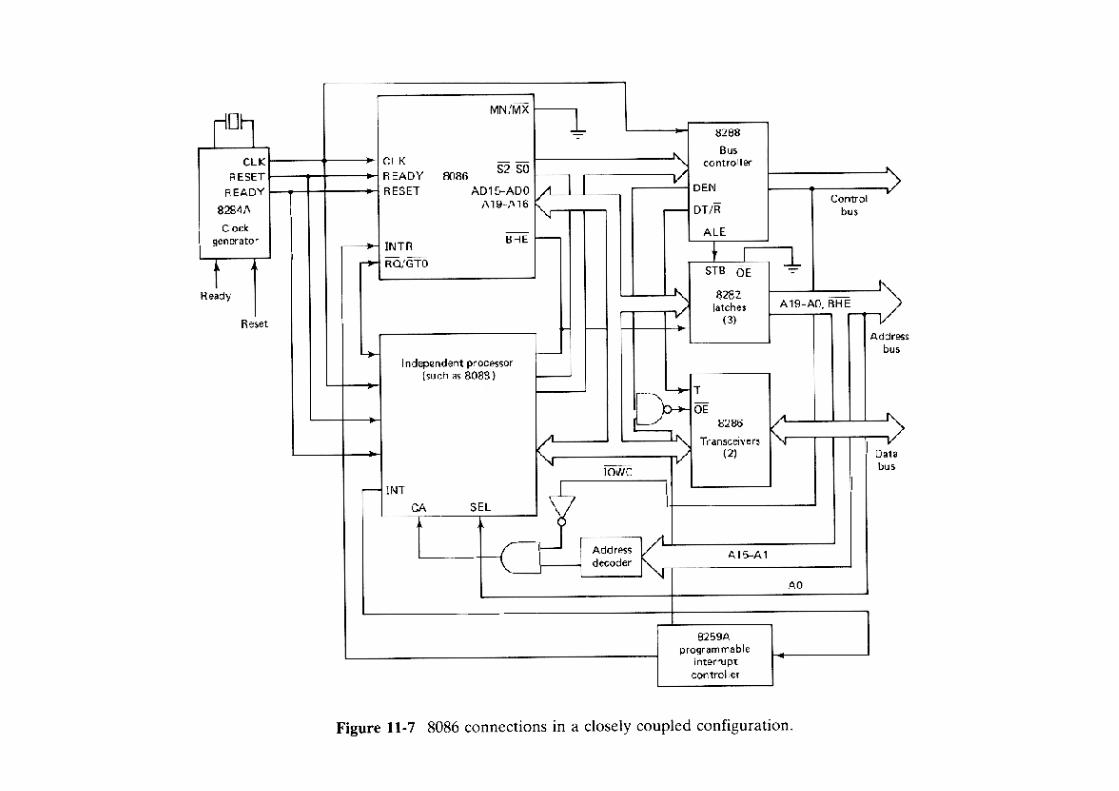
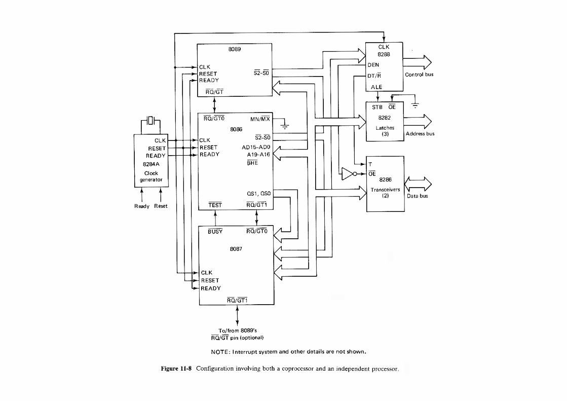
Closely Coupled Configuration
⇒ Coprocessor cannot take control of the bus, it does everything through the CPU
⇒ Closely Coupled processor may take control of the bus independently
- 8089 shares CPU’s clock and bus control logic
- communication with host CPU is by way of shared memory
- host sets up a message (command) in memory
- independent processor interrupts host on completion
Two 8086’s cannot be closely coupled

Closely Coupled Configuration

Loosely Coupled Configurations
A loosely coupled configuration provides the following advantages:
1. High system throughput can be achieved by having more than one CPU.
2. The system can be expanded in a modular form. Each bus master module is an independent unit and normally resides on a separate PC board. Therefore, a bus master module can be added or removed without affecting the other modules in the system.
3. A failure in one module normally does not cause a breakdown of the entire system and the faulty module can be easily detected and replaced.
4. Each bus master may have a local bus to access dedicated memory or I/O devices so that a greater degree of parallel processing can be achieved.
More than one bus master module may have access to the shared system bus ⇒ extra bus control logic must be provided to resolve the bus arbitration problem.
The extra logic is called bus access logic and it is its responsibility to make sure that only one bus master at a time has control of the bus.
Simultaneous bus requests are resolved on a priority basis. There are three schemes for establishing priority:
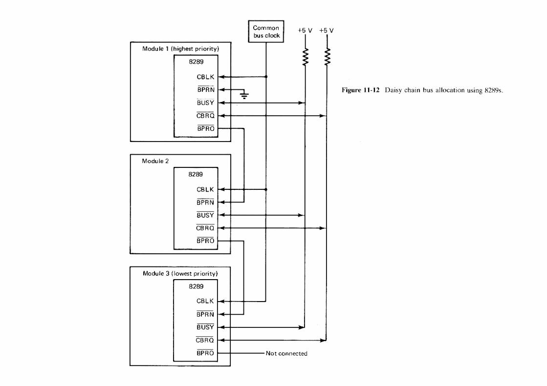
1.Daisy chaining. 2.Polling. 3.Independent requesting.

BPRN (BUS PRIORITY IN): returned to the arbiter to instruct it that it may acquire the multi-master system bus on the next falling edge of BCLK. BPRN active indicates to the arbiter that it is the highest priority requesting arbiter presently on the bus. The loss of BPRN instructs the arbiter that it has lost priority to a higher priority arbiter.
BPRO (BUS PRIORITY OUT): used in the serial priority resolving scheme where BPRO is daisy-chained to BPRN of the next lower priority arbiter.
CBRQ (COMMON BUS REQUEST): instructs the arbiter if there are any other arbiters of lower priority requesting the use of the multi-master system bus.
BCLK ( BUS CLOCK): The multi-master system bus clock to which all multi-master system bus interface signals are
synchronized.


In summary, processing modules of different configurations may be combined to form a complex, loosely coupled multiprocessor system.Each module in such a system may be:
1.A single 8086 or 8088 or an independent processor such as an 8089. 2.A cluster of processors consisting of an 8086 or 8088 and a coprocessor (such as an 8087) and/or independent processors. 3.A cluster of independent processors (such as two 8089s).
In addition, each module may include a local bus or a dedicated I/O bus.
11-2-4 Microcomputer Networks
The previous multiprocessor configurations have a common characteristics and that is that all processors share the same system bus.Thus, the interprocessor communications are through shared memory and processors must be physically located close to each other.
By using serial links, many microcomputer systems can communicate with each other and share some of the same hardware and software resources.Large systems of this type are called computer networks.