zenith system designs ”always looking up” blaise cole, paola alicea, jorge santana, scott modtl,...
TRANSCRIPT
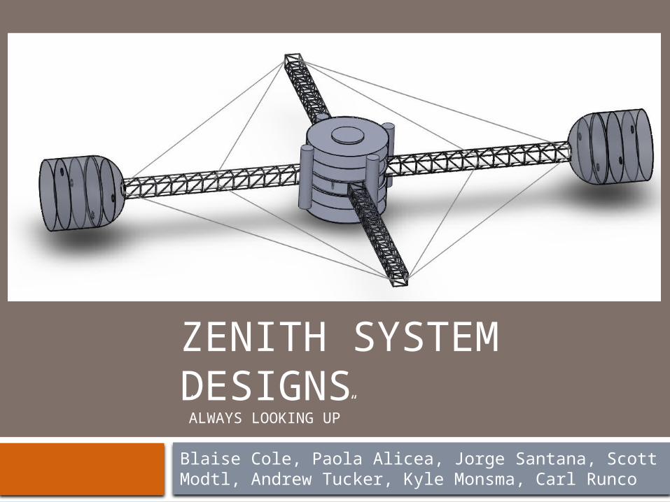
ZENITH SYSTEM DESIGNS”ALWAYS LOOKING UP”
Blaise Cole, Paola Alicea, Jorge Santana, Scott Modtl, Andrew Tucker, Kyle Monsma, Carl Runco
Mission Statement
Our mission is to expand the domain of humanity beyond the Earth for the betterment, preservation, and advancement of all humankind by creating a mobile habitat capable of long-duration, exploratory voyages while ensuring the physical and psychological well-being of its inhabitants.
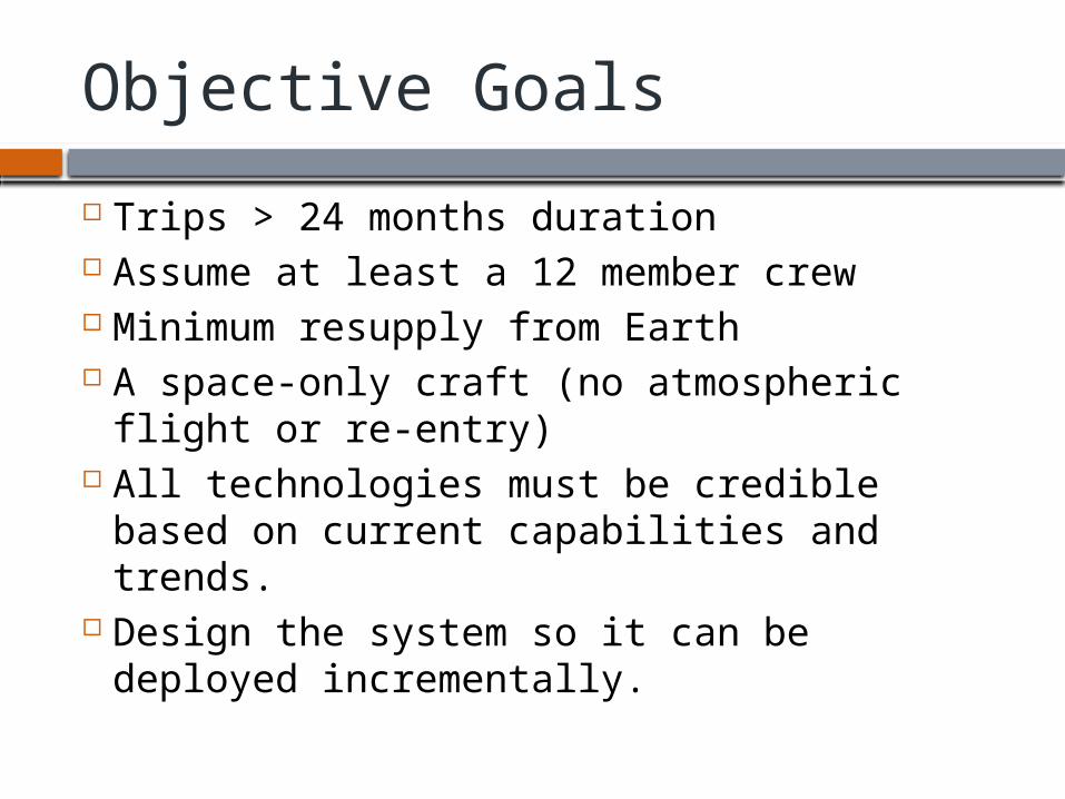
Objective Goals
Trips > 24 months duration Assume at least a 12 member crew Minimum resupply from Earth A space-only craft (no atmospheric flight
or re-entry) All technologies must be credible based
on current capabilities and trends. Design the system so it can be deployed
incrementally.
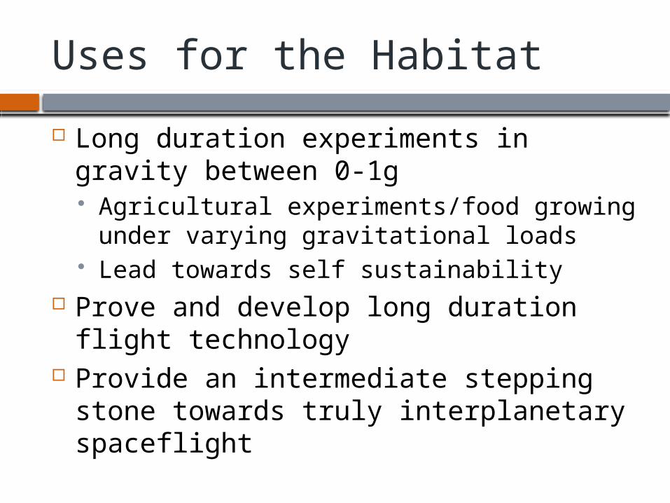
Uses for the Habitat
Long duration experiments in gravity between 0-1g Agricultural experiments/food growing
under varying gravitational loads Lead towards self sustainability
Prove and develop long duration flight technology
Provide an intermediate stepping stone towards truly interplanetary spaceflight
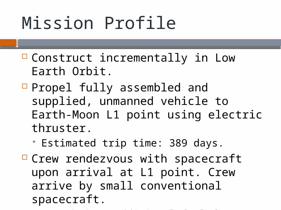
Mission Profile
Construct incrementally in Low Earth Orbit.
Propel fully assembled and supplied, unmanned vehicle to Earth-Moon L1 point using electric thruster. Estimated trip time: 389 days.
Crew rendezvous with spacecraft upon arrival at L1 point. Crew arrive by small conventional spacecraft. Crew brings additional fuel for propulsion
Two Main Questions
Simulating 1g in space Minimizing weight needed for shielding
while still providing sufficient protection
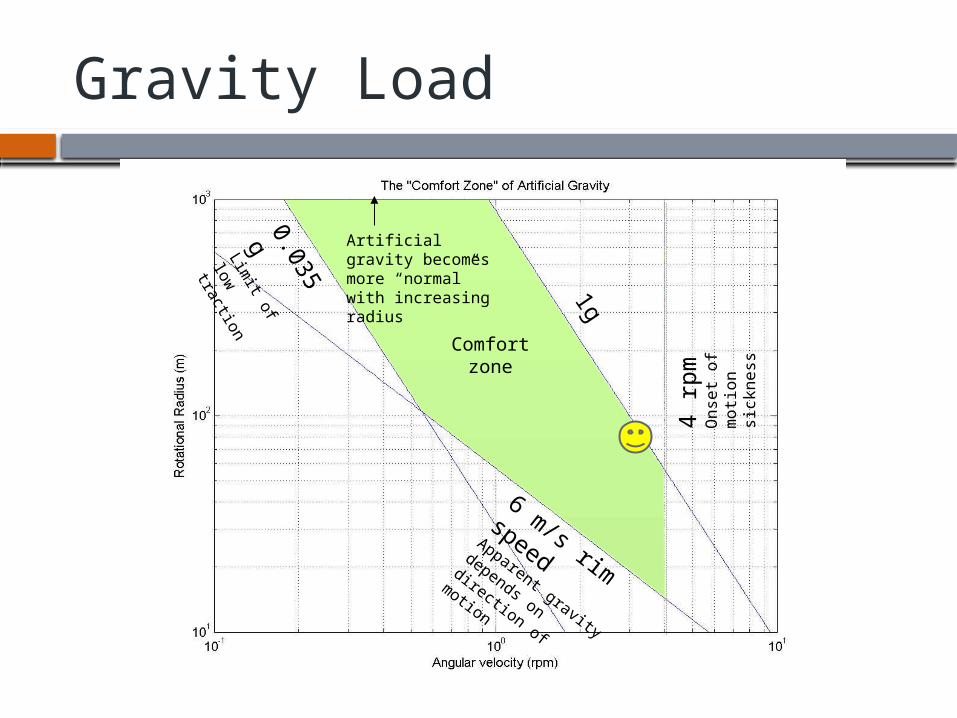
Gravity Load
1g
0.035 g
Limit of low
traction
6 m/s rim
speedApparent gravity
depends on direction of
motion
4 rp
mO
nse
t o
f m
otio
n
sick
ne
ss
Comfort zone
Artificial gravity becomes more “normal” with increasing radius
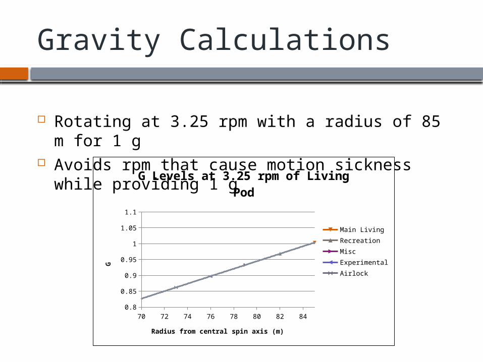
Gravity Calculations
Rotating at 3.25 rpm with a radius of 85 m for 1 g Avoids rpm that cause motion sickness while
providing 1 g
70 72 74 76 78 80 82 840.8
0.85
0.9
0.95
1
1.05
1.1
G Levels at 3.25 rpm of Living Pod
Main LivingRecreationMiscExperimentalAirlock
Radius from central spin axis (m)
G
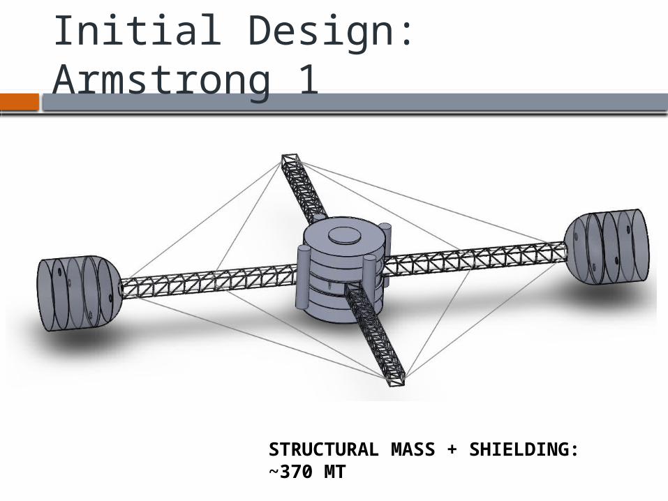
Initial Design: Armstrong 1
STRUCTURAL MASS + SHIELDING: ~370 MT
Shielding Details
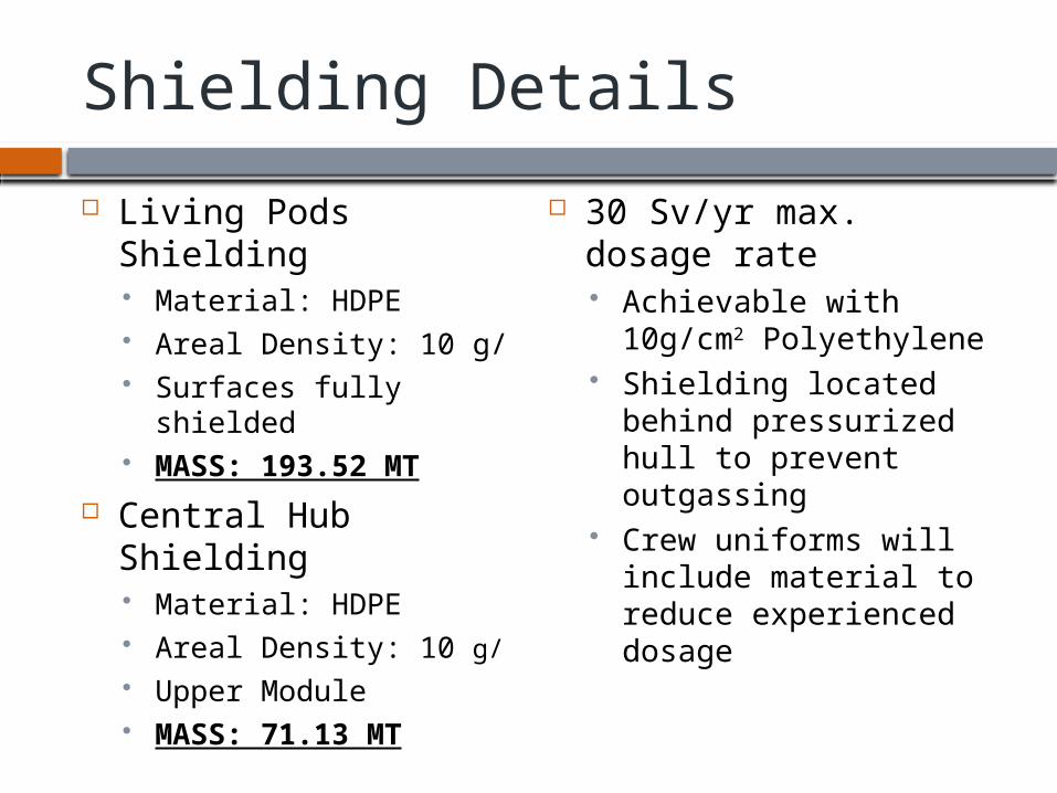
Living Pods Shielding Material: HDPE Areal Density: 10 g/ Surfaces fully shielded MASS: 193.52 MT
Central Hub Shielding Material: HDPE Areal Density: 10 g/ Upper Module MASS: 71.13 MT
30 Sv/yr max. dosage rate Achievable with
10g/cm2 Polyethylene Shielding located
behind pressurized hull to prevent outgassing
Crew uniforms will include material to reduce experienced dosage
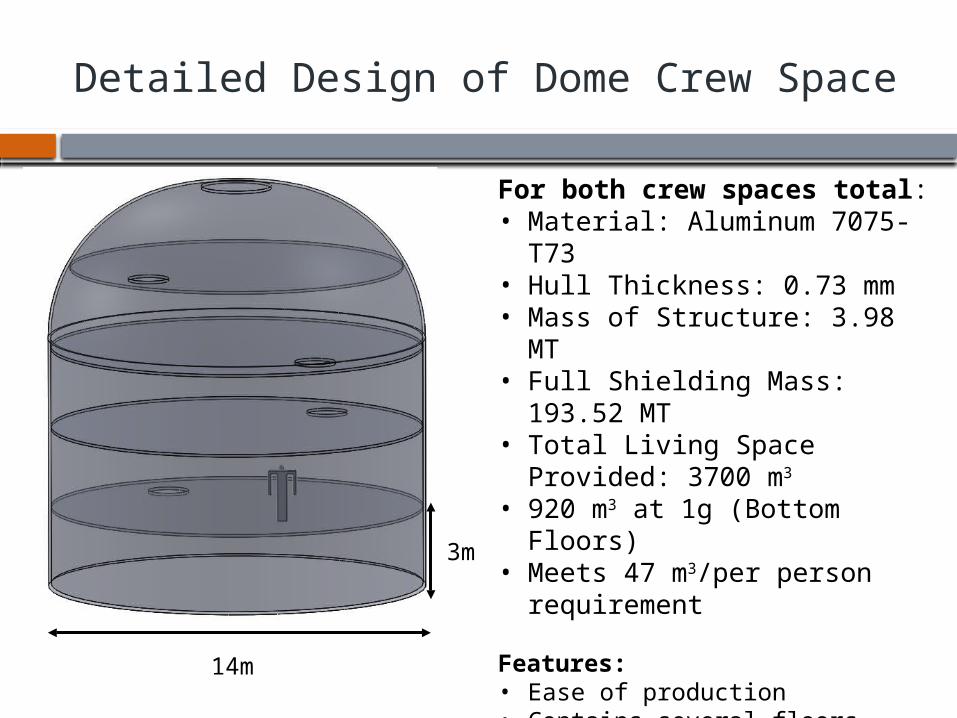
Detailed Design of Dome Crew Space
For both crew spaces total:• Material: Aluminum 7075-T73• Hull Thickness: 0.73 mm• Mass of Structure: 3.98 MT• Full Shielding Mass: 193.52 MT• Total Living Space Provided:
3700 m3
• 920 m3 at 1g (Bottom Floors)• Meets 47 m3/per person
requirement
Features:• Ease of production• Contains several floors• Larger living space than the Bell
design• Less surface area to shield than a
torus• If one pod were to fail, crew could
feasibly all live on one side in emergency situations
14m
3m
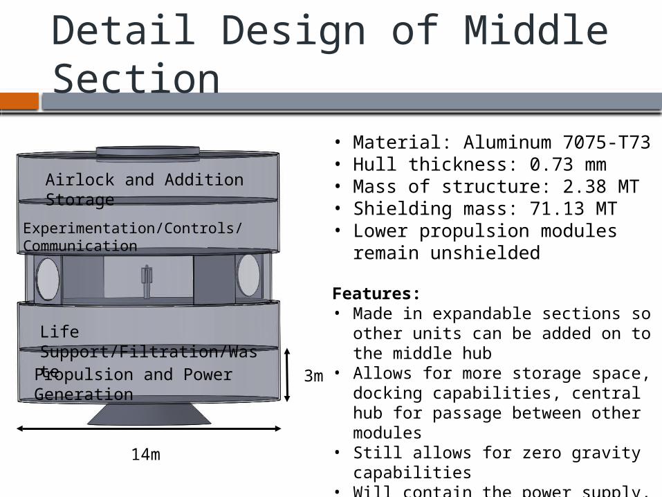
Detail Design of Middle Section
• Material: Aluminum 7075-T73• Hull thickness: 0.73 mm• Mass of structure: 2.38 MT• Shielding mass: 71.13 MT• Lower propulsion modules
remain unshielded
Features:• Made in expandable sections so
other units can be added on to the middle hub
• Allows for more storage space, docking capabilities, central hub for passage between other modules
• Still allows for zero gravity capabilities
• Will contain the power supply, life support systems, and propulsion systems
3m
14m
Propulsion and Power Generation
Airlock and Addition Storage
Experimentation/Controls/Communication
Life Support/Filtration/Waste
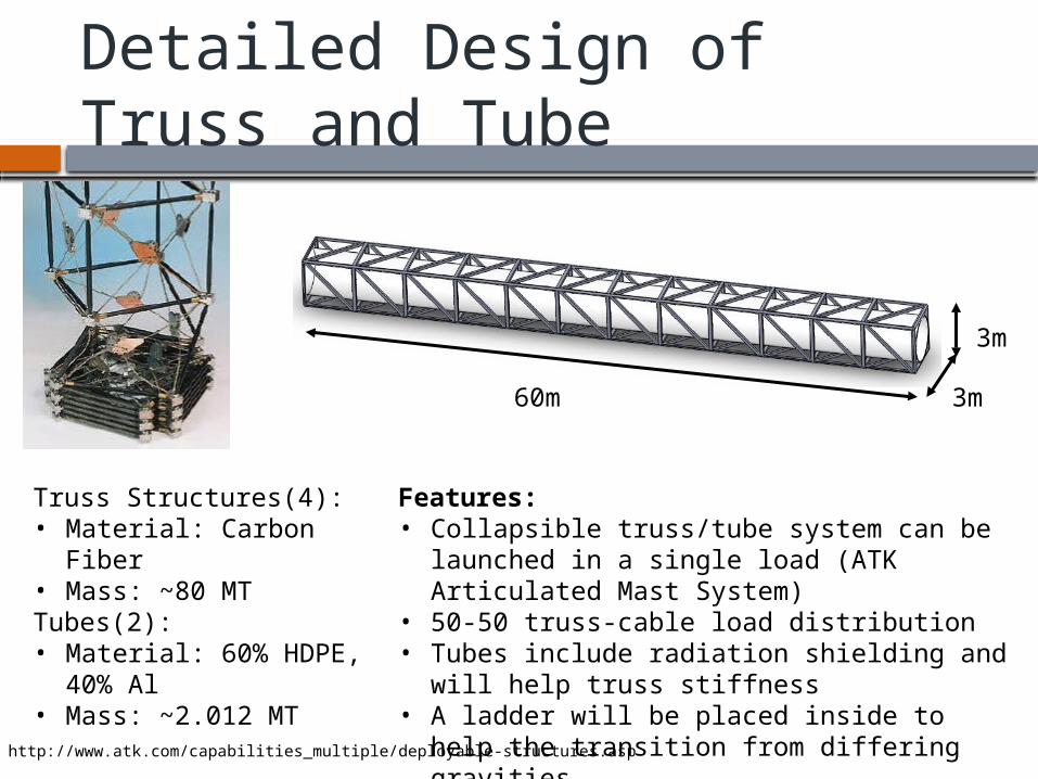
Detailed Design of Truss and Tube
Truss Structures(4):• Material: Carbon Fiber• Mass: ~80 MTTubes(2):• Material: 60% HDPE,
40% Al• Mass: ~2.012 MT
Features:• Collapsible truss/tube system can be
launched in a single load (ATK Articulated Mast System)
• 50-50 truss-cable load distribution• Tubes include radiation shielding and will
help truss stiffness• A ladder will be placed inside to help the
transition from differing gravities
60m
3m
3m
http://www.atk.com/capabilities_multiple/deployable-structures.asp
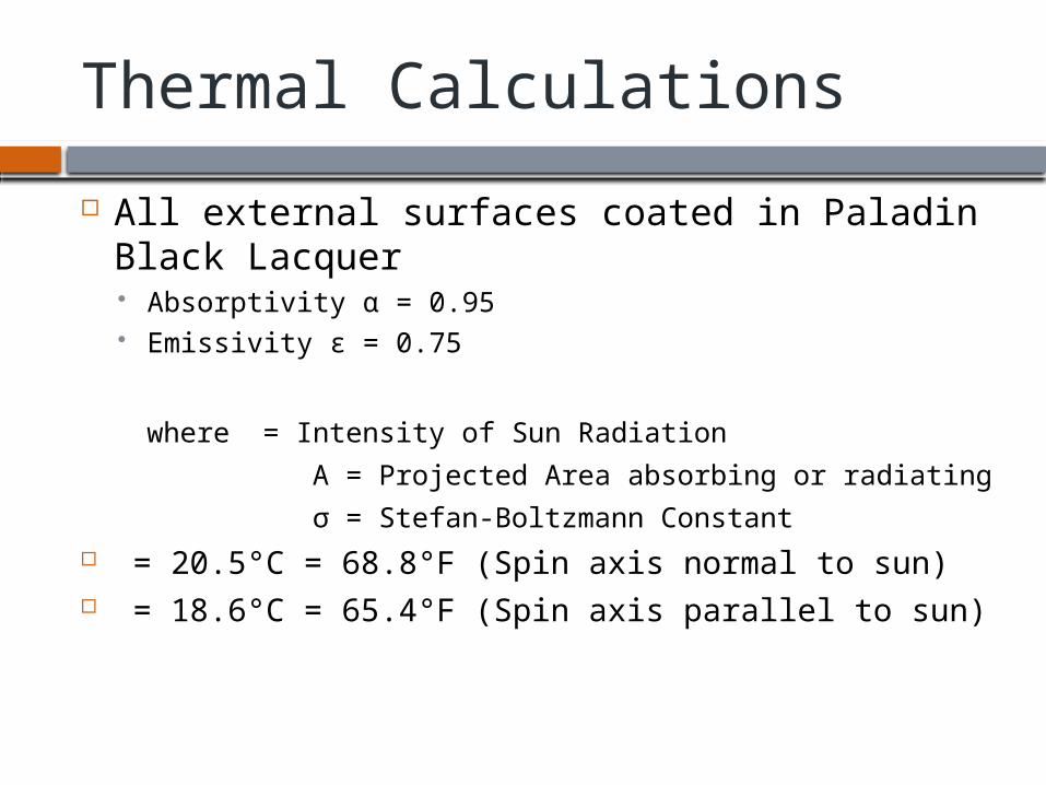
Thermal Calculations
All external surfaces coated in Paladin Black Lacquer Absorptivity α = 0.95 Emissivity ε = 0.75
where = Intensity of Sun Radiation
A = Projected Area absorbing or radiating
σ = Stefan-Boltzmann Constant = 20.5°C = 68.8°F (Spin axis normal to sun) = 18.6°C = 65.4°F (Spin axis parallel to sun)
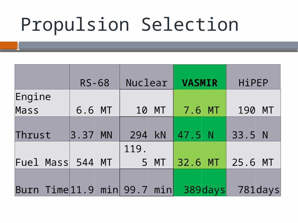
Propulsion Selection
RS-68 Nuclear VASMIR HiPEP
Engine Mass 6.6 MT 10 MT 7.6 MT 190 MT
Thrust 3.37 MN 294 kN 47.5 N 33.5 N
Fuel Mass 544 MT 119.5 MT 32.6 MT 25.6 MT
Burn Time 11.9 min 99.7 min 389 days 781 days
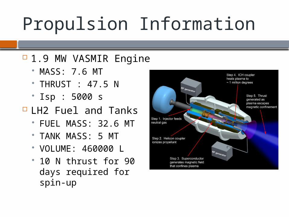
Propulsion Information
1.9 MW VASMIR Engine MASS: 7.6 MT THRUST : 47.5 N Isp : 5000 s
LH2 Fuel and Tanks FUEL MASS: 32.6 MT TANK MASS: 5 MT VOLUME: 460000 L 10 N thrust for 90 days
required for spin-up
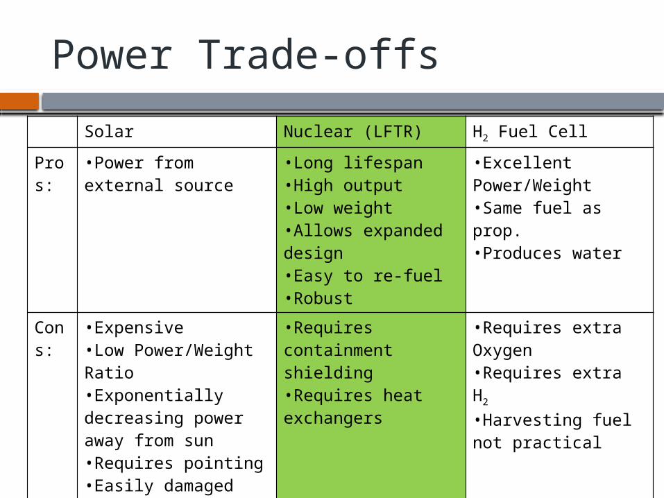
Power Trade-offs
Solar Nuclear (LFTR) H2 Fuel Cell
Pros:
•Power from external source
•Long lifespan•High output•Low weight•Allows expanded design•Easy to re-fuel•Robust
•Excellent Power/Weight•Same fuel as prop.•Produces water
Cons:
•Expensive•Low Power/Weight Ratio•Exponentially decreasing power away from sun•Requires pointing•Easily damaged
•Requires containment shielding•Requires heat exchangers
•Requires extra Oxygen•Requires extra H2
•Harvesting fuel not practical
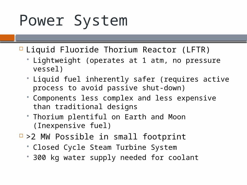
Power System
Liquid Fluoride Thorium Reactor (LFTR) Lightweight (operates at 1 atm, no pressure vessel) Liquid fuel inherently safer (requires active process
to avoid passive shut-down) Components less complex and less expensive than
traditional designs Thorium plentiful on Earth and Moon (Inexpensive
fuel) >2 MW Possible in small footprint
Closed Cycle Steam Turbine System 300 kg water supply needed for coolant
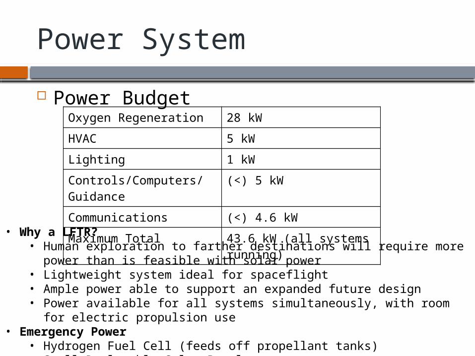
Power System
Power BudgetOxygen Regeneration 28 kW
HVAC 5 kW
Lighting 1 kW
Controls/Computers/Guidance
(<) 5 kW
Communications (<) 4.6 kW
Maximum Total 43.6 kW (all systems running)
• Why a LFTR?• Human exploration to farther destinations will require more power
than is feasible with solar power• Lightweight system ideal for spaceflight• Ample power able to support an expanded future design• Power available for all systems simultaneously, with room for electric
propulsion use• Emergency Power
• Hydrogen Fuel Cell (feeds off propellant tanks)• Small Deployable Solar Panels
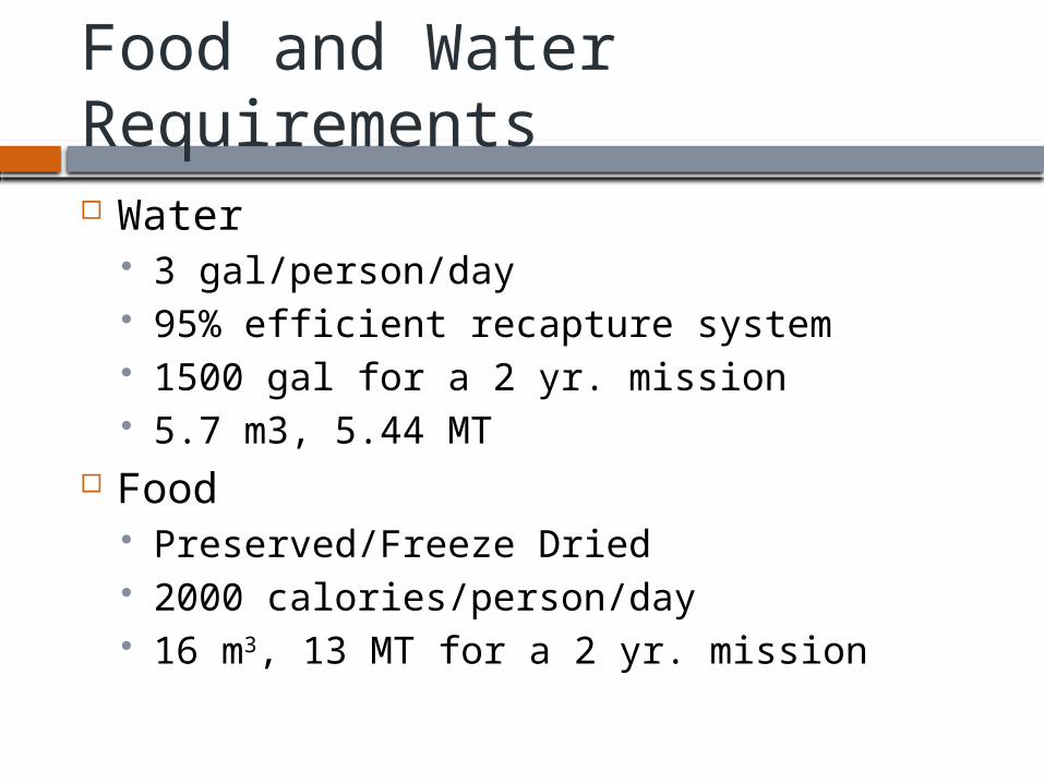
Food and Water Requirements Water
3 gal/person/day 95% efficient recapture system 1500 gal for a 2 yr. mission 5.7 m3, 5.44 MT
Food Preserved/Freeze Dried 2000 calories/person/day 16 m3, 13 MT for a 2 yr. mission

Life Support
Oxygen Re-captured by thermally breaking CO2 covalent bonds. Requires 28kW/15 min. burn, & 1 burn/day
Emergency Backups Li-OH Scrubbing Oxygen Candles
Estimated Timeline to Build and Complete
Stage 1 (36-48 months) Design of Living Systems and Main Module Design and fabrication of Truss sections Preform testing of docking and construction in a simulated
0 g environment. Testing and design of rocket configurations.
Stage 2 (18-24 months) Launching components into space to start construction
before moving to L1. Stage 3 (13-15 months)
After building is complete, supply and begin launch into L1 Stage 4 (4 days)
Send astronauts into space to rendezvous with Armstrong 1
Launch Considerations
Soyuz inexpensive since the design cost has been spread over so many missions.
If we have many launches, economies of scale will become applicable, driving costs down per launch.
Atlas V considered most viable launch vehicle for our needs, however modules can easily be split and sent using smaller vehicles. Current estimate is that 14 launches will be
needed for assembly in LEO, and an addition launch will be needed for the astronauts rendezvous
Advantages of this Design
Modular design can be assembled in pieces at a desired location
Modular design allows for expansion and different payloads/configurations
LFTR provides ample power for expanded configuration, and provides limitless oxygen
Design can be moved within the Earth-Moon system comparatively inexpensively using electric propulsion
Vehicle can idle almost indefinitely without crew aboard
The End
Derived Requirements
The spacecraft must have a propulsion system and sufficient propellant to be capable of moving itself out of Earth orbit, delivering the vehicle to its destination, and returning to Earth orbit, all within the specified mission lifetime.
The spacecraft will have self-contained life support systems capable of supporting a minimum of 12 crew for at least 24 months, and will provide them protection from all environmental factors including radiation.
The spacecraft will have dimensions sufficient to contain all support systems and cargo, and provide sufficient living space to the crew.
The spacecraft will have an amount of artificial gravity sufficient to maintain crew health for the duration of the mission.
Artificial gravity will be generated in a manner that reduces motion sickness. The vehicle must carry sufficient provisions for the crew to sustain them for at
least 24 months. The electrical power system must be capable of generating sufficient power for
all systems. Power must be continuously generated at or above this level for the duration of the mission.
The vehicle will contain features to allow the docking of external vehicles. All equipment will be launched by currently available payload delivery systems.
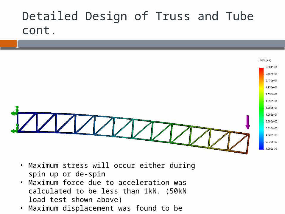
Detailed Design of Truss and Tube cont.
• Maximum stress will occur either during spin up or de-spin
• Maximum force due to acceleration was calculated to be less than 1kN. (50kN load test shown above)
• Maximum displacement was found to be 26mm
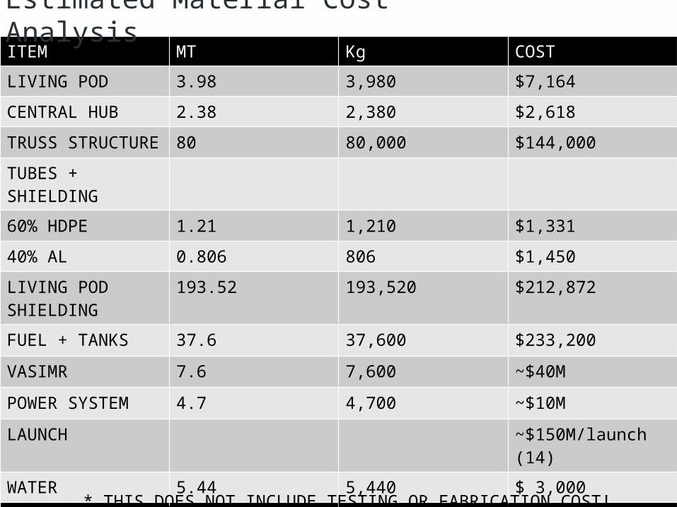
ITEM MT Kg COST
LIVING POD 3.98 3,980 $7,164
CENTRAL HUB 2.38 2,380 $2,618
TRUSS STRUCTURE
80 80,000 $144,000
TUBES + SHIELDING
60% HDPE 1.21 1,210 $1,331
40% AL 0.806 806 $1,450
LIVING POD SHIELDING
193.52 193,520 $212,872
FUEL + TANKS 37.6 37,600 $233,200
VASIMR 7.6 7,600 ~$40M
POWER SYSTEM 4.7 4,700 ~$10M
LAUNCH ~$150M/launch (14)
WATER 5.44 5,440 $ 3,000
TOTAL 403.666 403,666 ~$2.14B* THIS DOES NOT INCLUDE TESTING OR FABRICATION COST!
Estimated Material Cost Analysis
Additional Information
Other design configurations of Armstrong 1
Addition Information
If launching is a problem, the following design is compatible with current heavy launch systems
Armstrong 2
Additional Information
Other design configurations of Armstrong 2