zero emission strategies zero emission si … · powertrain 2030 the future drives electric? ......
TRANSCRIPT

"ZERO EMISSION STRATEGIES"
ISSUE 61 FEV CUSTOMER MAGAZIN
FEV HECS ECOBRIDDiesel
with 48V Hybridization
Systems for Medium-Duty Transport Vehicles
Strategies from Synthetic Fuels to E-Drives
SI HYBRID ENGINEHigh Tech or Low-cost?
RANGE EXTENDER
ZERO EMISSION

2
TABLE OF CONTENTS
3
The Hybrid-Optimal SI EngineZero Emission Strategies from Synthetic Fuels to E-Drives
FEV HECS ECObrid: Diesel with 48V Hybridization
01 "ZERO EMISSION" AND HYBRID TECHNOLOGIES
0818
24 2830
04The Future Drives Electric?Drivetrain Topologies in 2030
Development of Electric Vehicle Costs
FEV HECS ECObrid Diesel with 48V Hybridization
Energy Balance of 48V Mild Hybrids
Dear Readers,as the popular saying goes, all roads lead to Rome. This statement also applies with a view to CO2-neutral mobility. Whether through gradual electrification or the use of conventional combustion engines with alternative fuels, the opportunities and options are highly diverse. Finding the right mix for the corresponding boundary conditions seems to be one of the main challenges.
In the current issue of our customer mag-azine SPECTRUM, we not only present the results of our research on hybrid drives in the personal car and commercial vehicle segments, but also introduce our current studies on the costs and market pene-tration of electro mobility. In a technical discussion with experts from FEV, we also illuminate perspectives on renewable and synthetic fuels and their contribution to CO2-neutral mobility.
In addition to practical electrification proj-ects, such as our ECObrid diesel hybrid, we have been on the hunt for the optimum hybrid gasoline engine. This needs to be small, light and efficient in order to comply
Zero-Emission Strategies from Synthetic Fuels to E-Drives
High Tech or Low-cost? The Hybrid-Optimal SI Engine
BMS Algorithm for Battery State of Health Determination
Range Extender Systems for Medium-Duty Transport Vehicles
with emissions and spatial requirements while simultaneously fulfilling specific NVH requirements. Electrification constitutes an important change, and not just on the drive technol-ogy side. New challenges are also emerg-ing for the overall vehicle: for example, new solutions are required to address the reduced range of electrical vehicles, particularly in winter, and the lack of waste heat from combustion that is used for heating purposes. We have evaluated the energy conservation potential of radiant heating in an empirical study, and are presenting its findings in SPECTRUM.
We hope you enjoy reading it. Follow us on social media to keep up with the latest news from FEV.
Dr.-Ing. Norbert W. AltChairman of the Executive BoardFEV Europe GmbH
14
38Energy Savings with Help of Radiating Surfaces
02 VEHICLE DEVELOPMENT
PAGE 08 PAGE 18 PAGE 24
34

4
POWERTRAIN 2030
THE FUTURE DRIVES ELECTRIC? FEV STUDY EXAMINES DRIVETRAIN TOPOLOGIES IN 2030
The automotive industry is under pressure. We are experiencing major – even disruptive – changes. The public perception of the automobile is changing, and demands ecologically sustainable drivetrains. In the context of this market dynamic, electrification of the drivetrain has clearly set the stage for the public discussion and is also considered the strongest driving force in the industry. However, the sales volume for electrified vehicles is still strongly inhibited by high costs, weak infrastructure and short range. In 2016, less than 1% of all of the vehicles sold worldwide were primarily electrically driven. Against this background, market forecasts are certainly risky. But, despite this, an attempt has been made, below, to assess how powertrain populations will develop in the world's most important markets. It becomes clear that despite the uncertainties mentioned some reliable, central conclusions can still be made.
POWERTRAIN 203001 "ZERO EMISSION" AND HYBRID TECHNOLOGIES
THE MAJORITY OF ALL VEHICLES SOLD IN EUROPE WILL STILL HAVE COMBUS-TION ENGINES IN
2030
POWERTRAIN 2030
For further information please feel free to contact us
5
This market forecast focu-ses on the most important markets worldwide: Euro-pe, the USA and China. It
is based on a comprehensive study by FEV Consulting GmbH, which includes the following aspects:
� Legal framework conditions as CO2 emission limits �Regional and temporary driving bans for vehicles with combustion engines �Specific strategies of the automotive manufacturers who are dominant in each market �Development forecasts for important drivetrain components, like batteries � Infrastructure and development scenarios for fast charging technology � Forecasts of buying behavior based on market studies and socio-phenomenological developments, such as urbanization and car sharing (shared use as an alternative to ownership)
Drivetrain Topologies in Europe
The CO2 limits are continually being lowered in the European, American, and Chinese markets. The level of allowable CO2 emissions, which is lower on an absolute basis in Europe and China compared to the USA, is an indication of a strong need for electrification in those two markets. The anchor points were set at 2016
POWERTRAIN 2030POWERTRAIN 203001 "ZERO EMISSION" AND HYBRID TECHNOLOGIES
76
Drivetrain Topologies in the USA
When market expectations for Europe are compared to those for the USA, a di-vergent picture emerges, which can be summarized as follows:
� In the near future, sales in the USA will be geared towards the long ranges associated with liquid fuels and large combustion engines (6-cylinder and 8-cylinder) �Generally speaking, demands for CO2 emissions reduction take a back seat to reducing greenhouse gases, allowing a lower degree of electrification � In contrast to Europe, CO2 emissions associated with electricity generation are increasingly being taken into consideration in the assessment of vehicle emissions (trend towards “well-to-wheel” instead of “tank-to-wheel” approaches)
These aspects lead to lower electrifica-tion rates for the market in North America, compared to Europe. Consequently, it is expected that mild hybrid drives will only be fully rolled out by 2025. Additionally, it can be assumed that by 2030, 85 to 90% of all vehicles sold will still be equipped with combustion engines. The picture that has been painted can be expanded by the additional analysis of the Chinese market.
Drivetrain Topologies in China
The market expectations for China relative to Europe can also be summarized as core trends:
� Investments in infrastructure and strict legislation such as driving bans for combustion engine-driven vehicles in large cities, strongly encourage powertrain electrification �Already today, many future passenger car buyers in China drive electric two-wheel vehicles, so their behavioral pattern is a good match for electric drivetrains �At the same time, China has a highly cost-sensitive market segment that will, for a long time, be driven by purely combustion engine-driven passenger cars
These trends suggest a pronounced co-existence of internal combustion engine drivetrains and battery-electric vehicles in China. By 2030, only 50% to (a maximum of) 75% of all vehicles sold will have a powertrain equipped with an internal combustion engine. Concurrently, the degree of electrification of 90% of these drives will be limited to micro and mild hybrids, making the combustion engine the dominant drive unit.
In summary, it can be inferred that, even with the electrification of the powertrain increasing sharply, the majority of all
drives will still be equipped with com-bustion engines in 2030, and that these combustion engines will have to work in a variety of drive topologies. With increasing start-stop events, vibra-tions due to rigid body modes of the en-gine-transmission combination must be minimized in this operating condition.
Separate from the body-in-white con-siderations related to available space, there are additional NVH requirements for combustion engines in hybrid pow-ertrains. These can be summarized in a simplified manner as follows:
�With increasing start-stop events, vibration due to rigid body modes of the engine-transmission combination must be minimized during this operating condition. � It is desirable that the electric driving experience is not adversely affected by the operation of the combustion engine. This creates increased requirements with regard to acoustics and vibration excitation at comfort points, such as low vehicle seat acceleration.
IN CHINA, BY 2030, ONLY 50% TO (A MAXI-MUM OF) 75% OF ALL VEHICLES SOLD WILL HAVE A POWERTRAIN EQUIPPED WITH A COMBUSTION ENGINE.
in mild hybrids (2025: 33% market share), plug-in hybrids (2025: 13% mar-ket share) and battery-electric vehicles (2025: 8% market share) is expected. The more distant view towards 2030 is, today, still uncertain. The interaction of the development of the plug-in hybrid market share and the sales volumes for
battery-powered vehicles is not yet predictable and is primari-ly linked to the development progress of bat-tery technology (energy density and price), the
development of the charging infrastruc-ture, and the development of oil prices. An additional large influence is attributed to the "zero emission zones" currently being discussed publicly. If emission-free urban zones are broadly implemented, it is to be expected that this development will strongly encourage the purchase of purely electric vehicles in cities. Irrespective of this uncertainty, the following can be safely forecast for 2030:
�The majority of all vehicles sold in Europe will still have combustion engines in 2030 (75 to 80%). �A very high proportion of these combustion engines (about 90%) will be operated in hybrid powertrains.
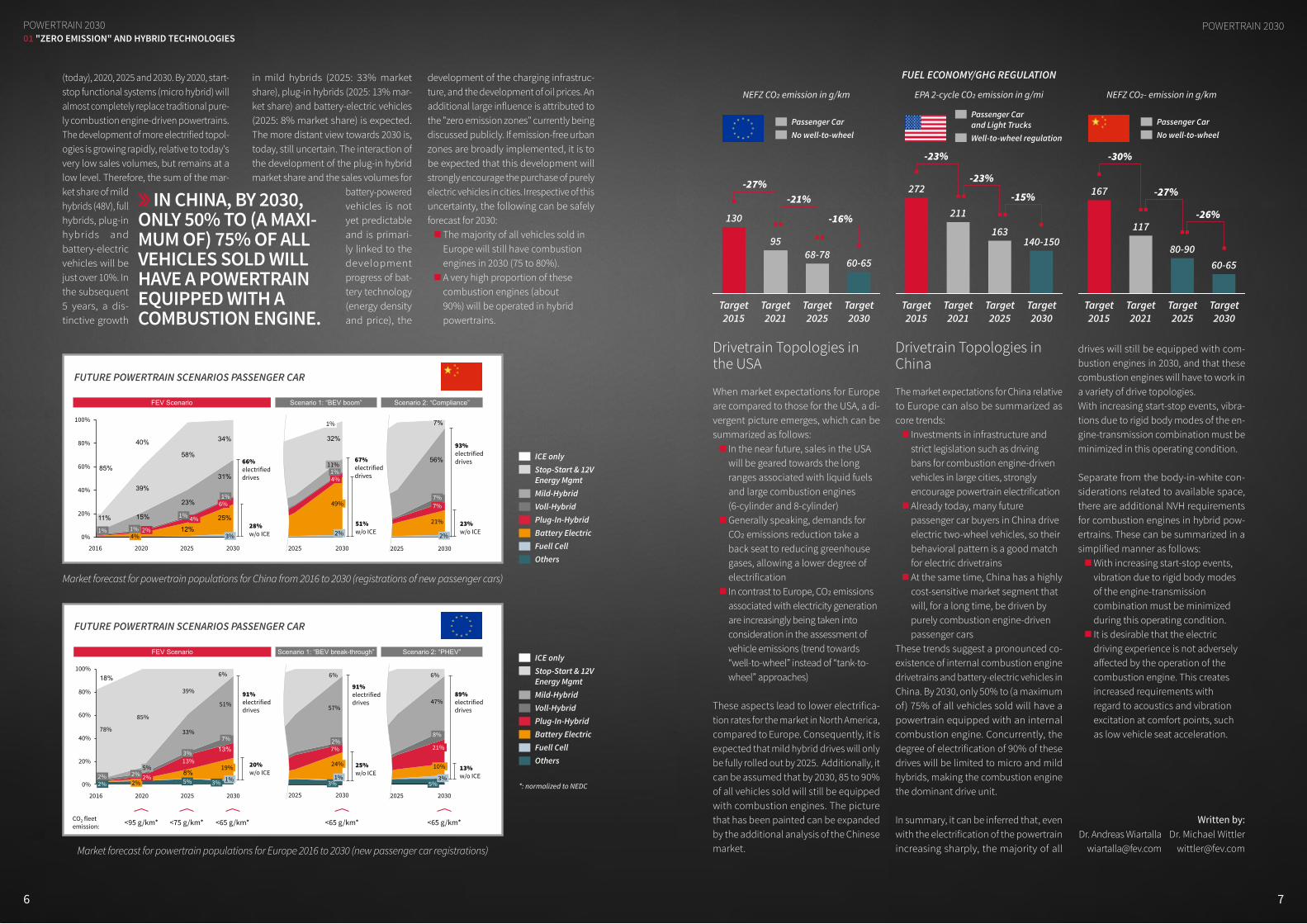
Market forecast for powertrain populations for Europe 2016 to 2030 (new passenger car registrations)
Market forecast for powertrain populations for China from 2016 to 2030 (registrations of new passenger cars)
FUTURE POWERTRAIN SCENARIOS PASSENGER CAR
ICE onlyStop-Start & 12V Energy MgmtMild-HybridVoll-HybridPlug-In-HybridBattery Electric Fuell CellOthers
*: normalized to NEDC
ICE onlyStop-Start & 12V Energy MgmtMild-HybridVoll-HybridPlug-In-HybridBattery Electric Fuell CellOthers
FUTURE POWERTRAIN SCENARIOS PASSENGER CAR
21%
56%
52%
7%
29%
12%
2025
0%1%3%4%
2030
2%
7%7%
52%
32%29%
4%12%
2030
2%
49%
4%1%
11%
1%
2025
1%3%12%
25%15%
23%
31%
39%
58%
34%
85%
40%
0%
20%
40%
60%
100%
80%
3%
20302016
1%
11% 4%
2025
1%
2020
4%2%1%
1%6%
FEV Scenario
28%w/o ICE
66%electrifieddrives
Scenario 1: “BEV boom” Scenario 2: “Compliance”
51%w/o ICE
23%w/o ICE
93%electrifieddrives67%
electrifieddrives
47%
74%
0
2030
5%3%
10%
21%
8%
2025
0%2%2%2%5%
57%
74%
0
2030
3%1%
24%
7%2%
2025
2%2%2%5%
Scenario 1: “BEV break-through”
8%
13%
13%
33%
51%
78%
85%
39%
6%18%100%
80%
60%
40%
20%
0%
2030
3% 1%
19%
7%
2025
5%
3%
2020
2%2%2%5%
2016
2%2%
Scenario 2: “PHEV”FEV Scenario
25%w/o ICE
13%w/o ICE
89%electrifieddrives
91%electrifieddrives
20%w/o ICE
91%electrifieddrives
<65 g/km*<75 g/km*<95 g/km* <65 g/km* <65 g/km*CO2 fleet emission:
6% 6%
FUEL ECONOMY/GHG REGULATION
NEFZ CO2 emission in g/km
Target 2015
Target 2015
Target 2015
Target 2021
Target 2021
Target 2021
Target 2025
Target 2025
Target 2025
Target 2030
Target 2030
Target 2030
NEFZ CO2- emission in g/kmEPA 2-cycle CO2 emission in g/mi
130
-27%
-23%
-23%
-15%
-30%
-27%
-26%-21%
-16%
272 167
117
80-9060-65
211
163140-15095
68-7860-65
Passenger Car No well-to-wheel
Passenger Car and Light TrucksWell-to-wheel regulation
Passenger CarNo well-to-wheel
Dr. Andreas Wiartalla
Written by: Dr. Michael Wittler
(today), 2020, 2025 and 2030. By 2020, start-stop functional systems (micro hybrid) will almost completely replace traditional pure-ly combustion engine-driven powertrains. The development of more electrified topol-ogies is growing rapidly, relative to today's very low sales volumes, but remains at a low level. Therefore, the sum of the mar-ket share of mild hybrids (48V), full hybrids, plug-in hybrids and battery-electric vehicles will be just over 10%. In the subsequent 5 years, a dis-tinctive growth

98
01 "ZERO EMISSION" AND HYBRID TECHNOLOGIESZERO EmISSION STRATEgIES
WITH THE NEW POWER-TO-GAS AND POWER-TO-LIQUID PROCEDU-RES, IN WHICH CO2 SERVES AS A CARBON SOURCE, CO2 SAVINGS OF WELL OVER
90% ARE ACHIEVED
ZERO EMISSION STRATEGIES The automotive industry is currently in the middle of one of the greatest upheavals in its history.
The new challenges surrounding connected and autonomous vehi-cles also pose major tasks for de-velopers, such as the choice of the correct and appropriate drive for achieving a minimum level of emis-sions. What's more, experts remain divided as to whether there is any ideal route to follow, or what that would be. Possible technologies include hybridization, partial or full electrification, or even fuel cells. It is a fact that the market penetration of these individual technologies con-tinues to fall below expectations, despite a number of government initiatives. Accordingly, the corre-sponding infrastructure is also only growing slowly.
These days, referring to the further potential of combustion engines sounds rather anachronistic, and is increasingly perceived by the public as the perspective of those who are permanently behind the curve and have not adopted the change in direction towards alternative drive forms, or have only done so insuf-ficiently. However, synthetic fuels actually offer an enormous amount of potential for ensuring sustainabil-ity and reduced pollution.
As an engineering service pro-vider with a strong focus on drive development, FEV not only offers its customers the development of advanced drive solutions, but also provides assistance and advice in the selection of drive concepts. In SPECTRUM, experts from FEV and RWTH discuss e-mobility, fuel cell drives and synthetic fuels.
ZERO EmISSION STRATEgIES
ZERO EMISSION STRATEGIES FROM SYNTHETIC FUELS TO E-DRIVESFEV AND RWTH EXPERTS DISCUSS FUTURE DRIVE CONCEPTS WITH REGARD TO ZERO CO2 EMISSIONS
„MARK IT ZERO“

10 11
ZERO EmISSION STRATEgIESZERO EmISSION STRATEgIES01 "ZERO EMISSION" AND HYBRID TECHNOLOGIES
Mr. Adomeit, as the Executive Engineer for Thermodynam-ics at FEV, you also research alternative fuels. What are the advantages of these diverse technologies in terms of emis-sions?
Adomeit: With the new power-to-gas and power-to-liquid procedures, in which CO2 serves as a carbon source, CO2 savings of well over 90% are achieved. Previously, every carbon atom released into the en-vironment from exhaust as CO2 would be absorbed into the atmosphere. The same applies for second-generation biofuels. But here, only carbon that has already been converted into biomass through the photosynthesis of atmospheric CO2 is burned in the engine. In addition to CO2 reduction, these fuels can also be formulated so that harmful emissions can also be substantially reduced, such as through the synthesis of oxygenated fuels that produce far lower levels of soot than fossil fuels.
What are the applications for which synthetic fuels are espe-cially critical?
Heuser: On one hand, synthetic fuels are interesting for the passenger car sector. The attraction here lies in the fact that they can be used directly, whether in the form of an admixture with conventional fuels, or, depending on the fuel, as a pure substance and without substantial mod-ifications to cars. In this area, synthetic fuels can directly help to reduce harm-ful emissions and immediately increase the share of renewable energy in existing fleets in the mobility sector. An admixture of only 30% of OMEs into conventional diesel reduces soot emissions by up to 90% – without any complex adjustment of the engine.Furthermore, synthetic fuels are extremely important in any area where no alterna-tives exist for conventional liquid fuels with high energy density. This is especially the case for commercial vehicles, ships and aircraft. For the foreseeable future, the energy density of batteries will remain lower than liquid fuels by orders of mag-
nitude. In the examples mentioned, it is totally impossible to accommodate the necessary energy quantities with batteries due to the enormous volume and weight requirements. With the help of synthetic fuels, it becomes possible to ensure long-term, clean and sustainable mobility in this area.
You mentioned the optimization of existing fleets – at present, how far away are we from a more-or-less comprehensive introduction of alternative fuels, and which of the procedures mentioned will become established?
Heuser: Currently, the EU has stipulated that 10% of the ener-gy consumed in the transport sector be supplied from alter-native energy sources by 2020. However, it will still be several years before “e-fuels,” i.e. those from the oxymethylene ether group, are used to refuel in large quantities. We already know that these fuels can be created from CO2 and renewable energy, but the realization of this on an industrial scale still requires more investment. However, such investment requires the framework conditions to be clear for all participants – certainty is required for planning purposes. Adomeit: One critical factor in the prompt introduction of CO2-neutral fuels is their integration with existing infrastruc-ture. This can allow fuel components that can be mixed into current fuels to reduce the CO2 emissions of existing vehicle fleets immediately. We are currently researching combinations of renewable fuels that approximate standard market fuel char-acteristics very closely when blended.
Who exactly should develop these fuels to suit the market?
A MIX OF ELECTRIFICATION, OPTIMIZED COMBUSTION ENGINES AND SYNTHETIC FUELS IS HIGHLY PROMISING
Mr. Ogrzewalla: It appears that the public has already agreed to say farewell to the combustion engine. As the Vice President of Electronics & Electrification, do you see this as the end of an era?
Ogrzewalla: It is a fact that drive develop-ment is entirely dominated by electrifica-tion at present. In recent months, virtually every OEM has announced development programs to the tune of millions. Even for us, as a development service provider, electro mobility has been a fixed compo-nent of our engineering business for more than a decade. Nevertheless, it needs to be stated that despite all of the advantages, the market penetration of electric vehicles is still low – and so are the growth rates. This means that the combustion engine will still be with us for some time – whether as a part of hybrid systems, range extend-ers, or as the sole powertrain. Especially in long-distance traffic and the transport sector, there are currently no conceivable alternative solutions.
In your opinion, what would a practical solution for this look like?
Ogrzewalla: The goal of a balanced fleet strategy must be to offer needs-appropri-ate drive solutions that ensure sustainable and clean mobility. With these ends in mind, a mix of electrification, optimized combustion engines and synthetic fuels is highly promising – while e-vehicles can re-duce local emissions, especially for short distances and inner-city traffic, synthetic fuels have the potential to reduce the CO2 emissions of combustion engines to a minimum. These constitute an ef-fective means of reducing the emissions of existing fleets and directly increasing the proportion of renewable energy in the mobility sector. Paired with further optimizations in combustion processes, this could lead to a sustainable reduction of CO2 emissions, culminating in zero emissions.
Mr. Heuser, as the Managing Director of the “Tailor-Made Fuels from Biomass” excel-lence cluster of RWTH Aachen University, can you briefly tell us more about the various forms of synthetic fuel and how they are manufactured?
Heuser: The term “synthetic fuels” can be used to describe an extremely diverse range of fuel types. It generally refers to any fuel not manufactured on the basis of petroleum. However, there are still funda-mental distinctions within this designa-tion, such as between biofuels or e-fuels.
Traditional first-generation biofuels, such as bioethanol or biodiesel, are primarily obtained through the fermentation of seed or fruit sugars into ethanol, or the ester-ification of vegetable fats with (primarily fossil) methanol. The second generation of biofuels uses all plant material for fer-mentation into alcohols or for synthesis into long-chain hydrocarbons by means of the biomass-to-liquid procedure. In this process, the plant material is first converted into synthesis gas (CO and H2) under anaerobic conditions, and is then combined into long-chain hydrocarbons. Similar procedures are also applied to produce synthetic fuels from natural gas or coal.Hydrogenated vegetable oils (“HVOs”) are usually obtained from plant oils, but other fats can also be employed. These are converted to paraffinic fuels through the addition of hydrogen. In addition, there is also the new technol-ogy of power-to-liquid or power-to-gas. These technologies use electrolysis to generate hydrogen from renewable power and water. In conjunction with CO2, this can be used to produce methane, which is already used as a fuel for gasoline engines. However, these processes also allow for completely new fuels to be defined, such as the liquid oxymethylene ethers (OME) group. These are as liquid as normal die-sel fuel, and can be mixed with it easily as a result.
Adomeit: For development, it is extremely important that oil companies and automotive manufacturers work hand-in-hand. Combustion engines and fuels need to be seen as two sides of the same coin that both affect and depend on each other. Engines are developed with the fuel to be used in mind, and new fuels also need to be developed with a view of engine requirements and environmental priorities – particularly with regard to the reduction of harmful emissions and fuel consumption, but also, for example, maximum combustion pressure, ignition charac-teristics, cooling features and acoustic behavior. Heuser: As Dr. Adomeit said already, there will be no single developer. The appeal of synthetic fuels lies in the fact that we can influence their characteristics in a targeted manner,
and thereby develop concretely better fuels. In this process, we can also adjust the engines in a second step, so that we can substantially reduce both fuel consumption and emissions simultaneously. To achieve
this, however, we need close collaboration between science, industry and policy.
Keyword – Ecology: Is an e-drive more environ-mentally friendly than a traditional combustion engine that has been improved with alternative fuels?
Ogrzewalla: When you only consider the production of fuels from renewable energy up to its conversion in the vehicle, an electric vehicle would be the most environmentally friendly. The efficiency of an electric car is very high, and the vehicles drive with no emissions. In contrast, synthetic fuels have the disadvantage that every step in the manufacturing process reduces the overall level of efficiency of the chain. One aspect that is frequently left out of the discussion is the manufacturing
Exemplary overview of tailored fuels from renewable sources which can be used in ICE combustion systems
Focus: Power to fuelFocus: Biomass to fuel
SNGHVO Black liquor DME / OME
� Synthetic natural gascan be synthesizedusing CO2 and H2 fromregenerative electricity
� Di-methyl ether andOxymethylen ether canbe synthesized usingCO2 and electricity
� Biofuels from blackliquor (crude tall oil) arebased on a wasteproduct in paper industry
� Hydrotreated vegetableoils can be based onnearly any vegetable oilor waste fat
10 11

13
ZERO EmISSION STRATEgIES ZERO EmISSION STRATEgIES01 "ZERO EMISSION" AND HYBRID TECHNOLOGIES
of the vehicles. For an objective analysis, however, this is indispensable. In this area, electric cars are at a disadvantage compa-red to conventional drive systems. Battery production, in particular, is demanding and cost-intensive, and the necessary materials create new dependencies on the global market. Both the extraction of these materials and the recycling of the batteries put stress on the environment. However, if renewable energies can be used with unlimited availability – in the future, it will often be the case that more power is produced than can even be used – this fact will no longer play such a large role. In this context, synthetic fuels offer an ideal technology for storing excess power in chemical form.
What role can fuel cells play in the future?
Ogrzewalla: Fuel cells could prospective-ly be used as a supplement to battery technology, or even replace it entirely. The hydrogen usage of fuel cells exhibits minimal CO2 emissions, since hydrogen does not contain any carbon that would be converted to CO2 and its production requires the fewest steps. FEV has created a corresponding demonstration vehicle together with its development partners, in the form of the “BREEZE!” joint project. This involved integrating a fuel cell range extender with a Fiat 500 from our e-vehi-cle fleet in order to combat the e-vehicle range problem. This allowed us to achieve a range of about 280 km. A tank refill of hydrogen can be completed within a few short minutes, and travel can be contin-ued unhindered. However, this technology still faces the question of the necessary infrastructure, which is highly complex and thus very expensive. Not least of all, the series and small-series solutions of the last decade have failed. At present, however, there are more and more pilot projects in which public buses are being equipped with fuel cells. The advantage for regular transportation services lies in the fact that a comprehensive filling station network is unnecessary. A small number of filling stations at the transport company's depots is enough to supply the fleet permanently.
buyers continues to be concerns related to range. In Germany, where the car has a special significance, users are reluctant to own a vehicle that does not cover all eventualities. This is illogical, however, since there is no need for a combustion engine for situations such as inner-city driving. An additional combustion engine would simply serve as extra weight for
most drives, which is anything but efficient. Various studies have arrived at the result that as much as 87% of all trips could be covered by an e-vehicle. The success of electro mobility thus requires an ecosys-tem of specific services and new business models and, above all, a change in think-ing on the part of consumers. In addition, advanced, quick-charging technologies
can also contribute to success, since this will guarantee the range of electric cars for any trip.
Until then, we will absolutely need to fall back on other, additional technologies. As mentioned before, there are no alterna-tives at all for long-distance traffic.
Jürgen [email protected]
Benedikt [email protected]
Dr. Philipp Adomeit [email protected]
We have now talked a great deal about the alternatives to elec-tromobility. Due to the large number of possible technologies, the development, infrastructure and, not least of all, marketing costs will increase enormously as a matter of course. Why is it impossible to focus on a single technology?
Ogrzewalla: At present, there simply is not a panacea for emissions-free mobility. User behavior is too diverse, and the systemic strengths and weaknesses of various drive forms are too different. In my opinion, however, the essential message is the fact that needs-appropriate drives are the key to success. Not every powertrain can be reasonably employed for every objective. For e-vehicles, one of the major obstacles for
PM/NOx emission reduction with OME use in Diesel test engine
10,80,60,40,200
0,5
1
1,5
2
2,5
3
Ind.
spec
. PM
/ g/
kWh
Ind. spec. NOx / g/kWh
35:65 OME1-Diesel80:20 OME1-Diesel27:73 OME35-Diesel100:0 OME35-DieselDiesel
10,80,60,40,200
0,1
0,2
0,3
0,4
0,5
Ind.
spec
. PM
/ g/
kWh
Ind. spec. NOx / g/kWh
35:65 OME1-Diesel80:20 OME1-Diesel27:73 OME35-Diesel100:0 OME35-DieselDiesel
Interview Partners:
JOIN OUR UPCOMING CONFERENCE
ZERO CO2
MOBILITY9th - 10th November 2017,HOTEL PULLMANN QUELLENHOF, AACHEN
13
FEV’s new international conference on “Zero CO2 Mobility” offers a highly focused platform for strategic discussion on the potential and performance of various zero emission strategies ranging from battery technologies to fuel cells and e-fuels. For more information please visit: http://www.fev.com/zero-co2-mobility
12

01 AUS FORSCHUNG UND ENTWICKLUNGCOSTS OF ELECTRIFICATION
1514
COSTS OF ELECTRIFICATION01 "ZERO EMISSION" AND HYBRID TECHNOLOGIES
COST DEVELOPMENT OF ELECTRIC VEHICLES CONSIDERING FUTURE MARKET CONDITIONSMARKET STUDY AND COST ANALYSIS OF ELECTRIC, HYBRID AND FUEL CELL VEHICLES
With a market share of only about 1% of new vehicles sold, battery driven electric vehicles and plug-in hybrid vehi-cles (“xEVs”) stand, from a European market perspective, far below expectations. In Germany, the xEV share is 0.6%; corresponding to about 25,000 vehicles sold in 2016. Germany is below the EU average. It is clear that the purchase and tax subsidies from the German government have, so far, not had a significant impact: In the first 3 months, only 4,500 sales were realized. Despite the subdued market demand, the number of public charging stations for electric vehicles tripled between 2015 and 2016. Against this background, FEV Consulting conducted a market and cost study to answer the question of how electric vehicle costs will develop in the future under conditions of increased sales volumes, growing demand for raw materials, and developing production capacities. The main objective is to assess the extent to which xEV vehicles can be cost competitive with conventional vehicles and which powertrain type will dominate the market.
COSTS OF ELECTRIFICATION
BY 2025, BEVS WITH A 300 KM RANGE CAN BE REALIZED ON THE SAME COST LEVEL AS THEIR MILD HYBRIDIZED COUNTERPARTS
FEV’s study answers the following core questions:
�What are the latest trends in electrification and hybridization? �What are key market and technology trends regarding xEVs towards 2025/30? �How high are costs for alternative powertrains today, and what will they be in 2025/30? �What are the primary cost drivers and how will they develop? �Will combustion engines still be the cost leaders in 2025/30? �Which additional costs are expected in order to meet statutory and supervisory requirements? �How cost competitive will fuel cell technology be in 2025/30?
Driven by "diesel gate", statutory regulations, regulatory pressure and technological advances, alternative drives (or xEV vehicles) have developed into a key trend in the automotive sector. Many European OEMs are convinced that the tipping point for electric vehicles will soon be reached: OEMs and suppliers are currently investing heavily in the development of their EV fleet and EV component portfolios. Volkswagen just recently released the launch of its xEV platform (MEB) with a goal of achieving a 600 km electric driving range in its compact car concept, “ID.” Daimler showcased an electric SUV Coupé called “Generation EQ,” at the Paris Motor Show that is based on a dedicated EV
COSTS OF ELECTRIFICATION
15
architecture. Other manufacturers are planning similar concepts, including purely electric as well as hybrid, and fuel-cell electric vehicles with electric ranges exceeding 350 km. Aside from the regulatory and legislative motivation, the financial implications for OEMs over the next 10 years are still not clear. The question of whether xEVs will be able to attain a significant market share largely depends on future price competitiveness compared with their conventionally powered counterparts.
Humidifier SystemThermal Management, Coolant Pump, RadiatorMisc (Valves, Sensors, Piping)Hydrogen RecirculationOtherAir Compressor (CEM)
208
141337
374
438
443
1.328
496
500
645
653
1.954
conservative most likely progressive
4.505
3.061
2.701
125297
330
386
391
1.171
Exemplary cost split for selected fuel cell component in 2025 [in €]
Methodology and Assumptions
Several alternative powertrain vehicle concepts and a conven-tional compact vehicle were compared in a cost analysis study. The selected models included typical plug-in hybrids (PHEV), pure battery-electric vehicles (BEV) and fuel-cell electric vehicles (FCEV) in the compact car segment. In order to capture market and technology uncertainties, 3 scenarios were developed that reflect technology development costs and fluctuations in raw material prices. For all 3 scenarios, a set of boundary conditions were determined to allow a fair cost comparison between the different concepts.
Selected boundary conditions for the 2016 cost baseline:
� Vehicle segment: Compact car �Baseline vehicle for cost comparison is a conventional ICE with start-stop and 12V � Low production volume for Fuel Cell Vehicles �Battery specifications based on current market concepts
Selected boundary conditions for the 2025 cost forecast:
� Vehicle segment: Compact car �Conventional baseline vehicle is MHEV (48V) with an additional 12 kW of electric power �Production volume for FCEV has been increased to 50 thousand units �Higher specific energy [Wh/kg]
Selected vehicle concepts for cost comparison of future xEVs
VEHICLE CONFIGURATIONS
CONV. ICE (w/ stop-start & 12V energy mgmt.) 110 kW POWER 962 KM RANGE (NEDC)
P2 HYBRID110 + 80 kW POWER 940 + 50 KM RANGE (NEDC)
PURE EV100 kW POWER 600 KM RANGE (NEDC)
PURE EV60 kW POWER 300 KM RANGE (NEDC)
FULL HYBRID114 kW POWER 658 KM RANGE (NEDC)
2016
48V MHEV110 + 12 kW POWER 962 KM RANGE (NEDC)
P2 HYBRID110 + 80 kW POWER 940 + 75 KM RANGE (NEDC)
PURE EV130 kW POWER 600 KM RANGE (NEDC)
PURE EV70 kW POWER 300 KM RANGE (NEDC)
FULL HYBRID130 + 60 kW POWER 740 + 57 KM RANGE (NEDC)
2025

16 17
COSTS OF ELECTRIFICATION 01 "ZERO EMISSION" AND HYBRID TECHNOLOGIES
Impact on the Automotive Industry
Fully electric drivetrains are far less com-plex than their conventional counterparts with internal combustion engines, since many components of a conventional drivetrain are no longer necessary. The sales potential of injectors, fuel pumps, filter systems and turbochargers is ad-versely affected by increasing EV sales. Conversely, the strategic importance of new components, such as the electric motor, battery and power electronics increases. For the future, manufacturers need to decide what share of the added value they want to provide from within (vs outsourcing). This decision is strongly influenced by endogenous factors such as cost competitiveness, exogenous factors such as raw material prices, vehicle range and future development of charging in-frastructures. Suppliers – especially those with a product portfolio focusing on conventional power-trains – will have to undergo a fundamen-tal transformation over the next 15 years, which can be subdivided into 3 steps:
1716
Modification / Change of powertrain configurations in a 15-year-timeframe
Conventional Hybrid Fully electric
Internal combustion engine (crankcase, cylinder head, crankshaft, conrod, camshaft, valves etc.) Modified / Downsized Modified / Downsized Deleted
Fuel supply (injectors, fuel pump, rails, tank, piping, filters) Modified Modified Deleted
Charging and exhaust gas (turbocharger, manifold, catalysts, filter, sensors, exhaust system) Modified Modified Deleted
Starter and generator Modified Modified Deleted
Transmission and clutch Modified Modified Modified/Deleted
Cooler water pump, air conditioning etc. Modified Modified Modified/Deleted
E-motor - New New
Battery system - New New
Power electronics - New New
Conventional Powertrain
2017
Technology Development
1 Strategic Analysis /Preparation of reorientation
2 Implementation of theReorientation and transition
3 Completion of the transition phase
Brand development
2015 2020 2025 2030
Electro mobility
1Today: Strategic Analysis and Pre-paration of RealignmentAlthough the industry is in a state of
upheaval, there is still partial restraint. On the one hand, the change to the develop-ment of alternative propulsion systems is already visible in the organizations of ma-jor manufacturers and large or specialized suppliers. On the other hand, traditional suppliers that are active in the internal combustion engine market are still in the preparatory phase.
22020: Implementation of the Re-alignment and Transition As soon as market shares of xEVs
have increased, product and service port-folios must be realigned and value chains have to be reorganized. The orchestration of an orderly ramp-down of the traditional business requires a solid strategic plan and dedicated implementation. It is very likely that the early inefficient suppliers will fall victim to the industry transition and exit the market. As a further conse-quence, the future R&D focus of the OEM’s will shift even more clearly toward electri-fication and other value-added product offerings, such as automation and (digital) mobility services.
COSTS OF ELECTRIFICATION
BY 2025 BEVS WITH A 300 KM RANGE (NEDC) CAN BE REALI-ZED AT THE SAME COST LEVEL AS THEIR MILD HYBRIDIZED COUNTERPARTS
Selected Study Results
In 2016, the manufacturing costs of plug-in hybrids and battery electric vehicles (PHEVs & BEVs) were about one-third higher than a conventional ICE-powered ve-hicle with a Start/Stop automatic transmission. Fuel cell electric vehicles (VCEV) manufacturing costs are nearly 5 times as high as those for a conventional ve-hicle. The reasons for this are lower sales volumes and high development cost in 2016.By 2025, it is expected that the electric range of xEV vehicles will nearly double, with marginal cost savings of approxi-mately 5% (Allrounder EV). Compared to mild hybrid comparison vehicles with 48V technology, the costs are about 20% high-er. The cost of fuel cell electric vehicles, with an electrical range of approximately
800 km, is expected to fall to one-fifth of today’s price, leaving a remaining cost gap of 60% compared to the 2025 base-line vehicle (48V mild hybrid). Battery costs are expected to decrease by 50%
for traditional OEMs due to economies of scale associated with increased produc-tion volumes and improvements in cell technologies. The electric capacity of a typical BEV is expected see a significant increase from 36 to 70 kWh (500-600 km).
In addition to the comparison of the total cost and the delta analysis of the select-ed xEV vehicle configurations, detailed powertrain cost splits are provided in the study for key components like the
electric motor, controller, bat-tery, transmission, etc. Each key component has been further broken down into the main cost drivers, including material costs as well as overhead costs which were determined using the FEV “should cost” methodology. Un-
certainties in future production volumes are considered in the “conservative,” “most likely” and “progressive” scenarios.
If you are interested in the details of the study or would like to discuss implications and possible actions, please don’t hesitate to contact us.
32025+: Completion of Transition PhaseDepending on the respective sce-
nario, market shares for conventional powertrains (ICE-only) will shrink signifi-cantly. In one radical scenario, ICE vehicle sales are likely to drop to 75% of the 2016 level. On one hand, as a result of shrinking market volumes, further (and even stron-ger) consolidation of the remaining suppli-ers in the field of conventional powertrains is expected. On the other hand, market participants will be well-positioned with an early strategic focus on the realignment and transition toward the new boundary conditions for the future xEV market and technology competition.
Written by Alexander [email protected]
Mirko [email protected]

18
01 AUS FORSCHUNG UND ENTWICKLUNGSI HyBRId ENgINES
19
SI HyBRId ENgINES
Architecture of Hybrid Powertrains
Hybrid drives are, by definition, com-binations of various drives in the same powertrain. Therefore, there is a correspond-ingly high number of possible constellations. In this broad study, the FEV experts focused on hybrid combinations with gasoline engines and topologies with particularly high mar-ket shares or particularly high market prospects. These are:
�Mild hybrid with 48V belt starter generator (BSG) �Mild hybrid with integrated 48V starter generator (ISG) �Plug-in hybrid (PHEV)
Cost-Benefit Comparison
A comprehensive technology matrix was examined within the framework of FEV’s study. This matrix includes turbocharged and naturally aspirated engine concepts with displacements from 1 to 3 liters. In
addition, the selection focuses on technol-ogies that are already in series production or show a high degree of maturity, indicat-ed by a series production launch within the next 3 years. All engines comply with
current and future emissions legislation such as EU6d and CN6b. They are operat-ed stoichiometrically (λ = 1) throughout the engine map, and they are equipped with particulate filters.
With the aim of identifying the optimal combustion engine for hybrid drives, these technologies have been evaluated re-garding their costs and CO2 emissions. The CO2 emissions are mean values from WLTP-L and -H. The cost scenarios relate to 2025 and a production volume of 200,000 drives/year. In addition, emission in RDE were tested and evaluated.
The result: Turbocharged 3-cylinder engines as well as naturally aspirated 4-cylinder engines with larger displacements are both suited to achieve low CO2 emissions. Rather simply designed "On/Off" technol-
ogy packages are also suited for the scaling of the performance requirements of the combustion engine for various hybrid drives. The conversion to a naturally aspirated 3.0 liter 6-cylinder engine with port fuel injection
(PFI), Atkinson cycle and cooled EGR neither appears favorable from the cost perspective nor from that of CO2 emissions.
Engine Variants for Mild Hybrids with 48V BSG
The electrification of the reference pow-ertrain with 48V BSG without changes to the combustion engine costs 740 € and reduces the CO2 emissions by 8.6 g/km which means costs of 86 €/g-CO2. Start-ing with this drive, several technology combinations optimal for hybrids were identified. They arrived at the following
01 "ZERO EMISSION" AND HYBRID TECHNOLOGIESSI HyBRId ENgINES
18
HIGH TECH OR LOW COST?FEV INVESTIGATES THE OPTIMAL SI ENGINE FOR HYBRID POWERTRAINS
Recent market studies performed by FEV for Europe, the USA and China predict a shift toward environmentally sustainable drive systems. The main factor in this trend is the electrification of the drivetrain. Although the majority of all vehicles sold in Europe (75 to 85%) will still have a combustion engine in 2030, a high proportion of these com-bustion engines will be operated with hybrid powertrains. How can gasoline engines be designed to achieve low CO2 emissions in different hybrid topologies (as mild hybrid, plug-in hybrid, etc.) at optimal cost? FEV addressed this question in a broad study based on a D-segment vehicle. The reference powertrain was a conventional powertrain with a 2.0 liter gasoline engine (135 kW, TC DI with a 2-stage variable valve train and Miller cycle), a 7-speed dual clutch transmission and a 12V electrical system.
SI HYBRID ENGINES
Evaluation of technology packages of gasoline engines for mild hybrids with 48V belt-driven starter generator (BSG mild hybrid) relative to the reference powertrain with regards to the ratio of costs and CO2 emissions
TURBOCHARGED 3-CYLINDER ENGI-NES AS WELL AS NATURALLY ASPIRA-TED 4-CYLINDER ENGINES WITH LAR-GER DISPLACEMENT ARE BOTH SUITED TO ACHIEVE LOW CO2 EMISSIONS AT LOW COSTS
Reference powertrain : 2.0 L TC DI w/ Miller, int. exh. manifold, dual-VVT, Miller, intake-2-stage-VVL, start/stop and 12 V energy management, 143 g/km CO2 in WLTP
Delta
cost
s / €
Delta CO2 reduction / (g/km)
48 VOLT P0 MILD HYBRID Ref. engine in hybrid-powertrain
3-cylinder
High Tech
4-cylinder
* “Soft”-Atkinson
6-cylinder
SymbolDisplacement /L 1.5 1.5 1.4 1.3 1.3 2.0 2.5 2.5 3.0
1 Fuel injection DI DI DI DI DI DI DI DI PFI2 Int. exh. manifold X X X X X X X X X3 Turbocharger X X X X X X4 Intake VVT X X X X X X X X X5 Exhaust VVT X X X X X X X X6 Miller/Atkinson X X X * X * X7 2-st.-intake-VVL X X8 1050 °C turbine X X9 2-stage TC X10 VTG X11 Var. int. manifold X X12 CDA X13 VCR X X14 Water injection X15 cEGR X

01 AUS FORSCHUNG UND ENTWICKLUNGSI HyBRId ENgINES
2120
Therefore, the powertrain has a lower CO2 emission reduction of 8.9 g/km, but only costs 460 € (52 €/g-CO2 is achieved). If inlet valve lift variability and the Miller cycle are retained for the 3-cylinder engine, the performance requirement can also be met via a high temperature-proof turbine with variable geometry (950 °C VTG). A CO2 emission reduction of 13.1 g/km is therefore achieved at 46 €/g-CO2. The technology package inlet valve variability, Miller cycle and 2-stage charging system can also be replaced at a favorable cost and CO2 emissions level by a 2-stage VCR system (44 €/g-CO2).
Water injection can also serve as a sub-stitute technology and allows a further downsizing to 1.3 liter with its strong knock-suppressing and simultaneously performance-enhancing effect. This vari-ant with direct water injection does not yet have the same production maturity as VCR, but will yield good ratios for costs and CO2 emissions for the 2025 horizon in hybrid drives, too (33 €/g-CO2 is achieved).
conclusions for the D-segment vehicle evaluated in the WLTP cycle: Naturally aspirated 4-cylinder engines and turbo-charged 3-cylinder engines are particularly well suited for use in a mild hybrid with a 48V belt-driven starter generator. Nat-urally aspirated engines require 2.5 liters displacement, variable valve timing on the inlet and outlet sides (dual VVT), direct fuel injection (DI) and a variable intake system to meet performance demands. The costs of the BSG drive train can be reduced to 490 € by conversion to a natu-rally aspirated engine with a simultaneous increase of the CO2 emission reduction to 10.4 g/km (47 €/g-CO2 is achieved). With the addition of cylinder deactivation (CDA), the costs increase again to 560 €; however the CO2 emission reduction is disproportionately increased to 12.1 g/km (46 €/g-CO2 is achieved).
With the simplification of the combustion engine to a 3-cylinder engine and the elim-ination of the inlet valve lift variability, the Miller cycle has to be omitted to contin-uously meet performance requirements.
gines with knock-reducing technologies like Miller valve timings or VCR and larger, naturally aspirated engines like a 2.5 liter 4-cylinder with PFI, Atkinson cycles and cooled exhaust gas recirculation (cEGR) meet this requirement.
Assessment Under Real Driving Conditions
In the WLTP cycle, the influence of the combustion engine on the CO2 emissions reduction de-creases with an increasing degree of electrification. At the same time, the increas-ing influence of the e-motor allows for the simplification of combustion engine technologies, thus achieving cost benefits.
The influence of the combustion engine increases under real driving conditions (RDE) compared to the WLTP cycle signifi-cantly. This is due to higher loads and a smaller pro-portion of electric driving. Tur-bo-charged engines with more advanced technology have a more favourable cost
and CO2 emissions ratio under these terms of comparison. In the light of real driving conditions, the use of a variable inlet valve lift (VVL) or the compres-sion ratio (VCR) appear advantageous. In the Charge-Sus-taining-Mode, high tech turbo-charged engines with knock-inhibiting technol-ogies gain clearly, because they drive a heavy vehicle (battery weight) without purely electric driving.
Vehicle Integration Concepts
Package and NVH are of special impor-tance in the integration of the combustion engine into hybrid powertrains. Additional drive components compete for consis-tently limited space. At the same time, electrification can be employed in an intelligent way with the simplifications
01 "ZERO EMISSION" AND HYBRID TECHNOLOGIESSI HyBRId ENgINES SI HyBRId ENgINES
Engine Variants for Mild Hybrid with 48V ISG
Expanding the hybrid functionalities by repositioning the electric engine from a P0 to a P2 layout increases the cost of powertrain electrification to 990 € but leads to a CO2 emission reduction of 19.4 g/km compared to the reference power-train (51 €/g-CO2). The analysis shows that the technology package evaluation of a BSG mild hybrid is largely transfer-able to an ISG mild hybrid powertrain. Naturally aspirated 4-cylinder engines and turbocharged 3-cylinder engines are suitable for cost/CO2-optimized use in drives equipped with ISG.
Engine Variants for PHEV
The influence of the combustion engine technology package on achievable CO2 emissions reduction is small for the plug-in hybrid drive concept. The design is characterized by compliance with the performance requirements at optimal cost. Small, simplified turbocharged en-
and the elimination of existing compo-nents. FEV has developed a parametric procedure to be able to evaluate early concepts from a package perspective.
Again, FEV considered the D-segment vehicle with a transversely mounted com-bustion (“east-west”) engine for the 48V hybrid variants with belt-driven starter generators or starter generators, respec-tively, as well as with the P2 plug-in hybrid
powertrain.
The evaluation of the results revealed that the reference engine (4-cylinder 2.0 liter TC DI) has no significant space disadvantage in the P0 mild
hybrid configurations examined. This is primarily due to the elimination of the alternator, which compensates for the additional belt and belt-driven starter generator (BSG). As expected, the ISG variant in transverse mounting is less fa-vorable from a package perspective when comparing the mild hybrids. This is due to the extension in length caused by the ISG and the additional clutch.
3-CYLINDER ENGINES CAN REPLACE 4-CYLINDER ENGINES IN HYBRID DRIVES WITHOUT SIGNI-FICANT NVH DISADVANTAGES.
Gasoline engine technology packages ratio of cost and CO2 emissions for plug-in hybrids (PHEV) compared to the reference powertrain
Gasoline engine technology packages ratio of cost and CO2 emissions for mild hybrids with integrated 48V starter generator (ISG mild hybrid) relative to the reference powertrain
Reference powertrain: 2.0 L TC DI w/ Miller, int. exh. manifold, dual-VVT, Miller, intake-2-stage-VVL, start/stop and 12 V energy management, 143 g/km CO2 in WLTP
Delta
cost
s / €
Delta CO2 reduction / (g/km)
48 V P2 ISG Mild Hybrid Ref. engine in hybrid-powertrain
3-cylinder
High Tech
4-cylinder
* “Soft”-Atkinson
6-cylinder
SymbolDisplacement /L 1.5 1.5 1.4 1.3 1.3 2.0 2.5 2.5 3.0
1 Fuel injection DI DI DI DI DI DI DI DI PFI2 Int. exh. manifold X X X X X X X X X3 Turbocharger X X X X X X4 Intake VVT X X X X X X X X X5 Exhaust VVT X X X X X X X X6 Miller/Atkinson X X X * X * X7 2-st.-intake-VVL X X8 1050 °C turbine X X9 2-stage TC X10 VTG X11 Var. int. manifold X X12 CDA X13 VCR X X14 Water injection X15 cEGR X
0
200
400
600
800
1000
1200
1400
0 10 20 30 40
Del
ta c
osts
/ €
Delta CO2 reduction / (g/km)
# WLTP (AVERAGE L & H)
2025+
Hybrid opt. ICEs
0
500
1000
1500
2000
2500
3000
3500
4000
4500
5000
0 20 40 60 80 100 120 140
Del
ta c
osts
/ €
Delta CO2 reduction / (g/km)
4100420043004400450046004700
110 112 114 116 118 120
Del
ta c
osts
/ €
Delta CO2 reduction / (g/km)
P2 Plug-in-Hybrid
SymbolDisplacement /L 1.3 1.5 1.2 2.0 2.1 2.5
1 Fuel injection DI DI DI DI DI PFI2 Int. exh. manifold X X X X X X3 Turbocharger X X X X4 Intake VVT X X X X X X5 Exhaust VVT X X X X X6 Miller/Atkinson X X X * X7 2-stage VVL X X8 1050 °C turbine X X9 VCR X10 Var. int. manifold X11 cEGR X
3-cylinder 4-cylinder
High Tech
Hybrid opt. ICEs
# WLTP (AVERAGE L & H)
BSGISGHEV
* “Soft”-Atkinson
+-# WLTP
143 g/km
P2- Plugin Hybrid
2322
SI HyBRId ENgINES01 "ZERO EMISSION" AND HYBRID TECHNOLOGIESSI HyBRId ENgINES
For the plug-in hybrid, a critical package parameter value has now been exceeded ("No Go").
The naturally aspirated 4-cylinder variants reach the critical value already in the 48V mild hybrid variants and exceed it clearly in the plug-in hybrid. The increase in engine length in the transverse mounting is especially critical. The increase of the overall height in particular with regards to the transverse influence on passive pedestrian protection and noise encapsulation measures also reduces the package parameter. This cannot be compensated for by the elimination of the turbocharging components when the transition from the turbocharged to the naturally aspirated engine is made, as these can be placed in a comparatively flexible manner. The package parameter considers this flexibility, which leads to a lower weighting of the turbocharging components compared to other measures – for example, a change of the engine block.
All 3-cylinder variants allow for a significant relaxation of the space problem for the 48V mild hybrid variants. By way of an increase in the degree of downsizing (displacement reduction to 1.3 liter), a small advantage remains even for the plug-in hy-brid variant, whereas with a larger displacement (1.5 liter), the 3-cylinder engine is almost neutral compared to the reference powertrain.
Noise Vibration Harshness
FEV’s studies show that the NVH requirements for the combustion engine in the hybridized powertrain are controllable if suitable measures are considered in the design concept of hybrid drives. Examples are the increase in starter speed, the integration of balance shafts (or balancing weights with a high balancing degree), the adjustment of the engine mounting and the use of dual mass flywheels. With the help of such measures, 3-cylinder engines can replace 4-cylinder engines in hybrid drives without significant NVH disadvantages.
Emission Calibration Under Real Driving Conditions
The important influence of electrification is the intermittent decoupling of the combustion engine from vehicle propulsion. The connections observed here are more pronounced with an increasing degree of electrification. Therefore, a comparison between the emissions of the powertrains with the highest electrification differentiation was performed.
The highly electrified plug-in hybrid powertrain was examined with two "hybrid-optimized" combustion engines. In view of EU6d limits and RDE, both drives were equipped with a particulate filter. They did not need mixture enrichment for component protection (λ = 1 throughout the map), and had an injection system for reduced particle emissions (turbocharged engine: 350 bar DI and naturally aspirated engine with PFI).
The result: With a full battery, purely elec-tric, emission-free driving led to a clear reduction in route-specific particle emis-sions for all plug-in hybrid variants in the Charge-Depletion mode. With an empty battery, the particles increased compared to the reference powertrain because the engine had to move the heavier plug-in hybrid vehicle.
Particle Emissions in Electrified Powertrains
Particle emissions in the electrified pow-ertrain (PHEV) shift when compared to the purely combustion engine-driven vehicle dependent on the battery charge status. Generally, the emissions are lowered by emission-free electric driving. When using a plug-in hybrid with an empty battery, a particle emission increase of 18% occurs. The main effect is that purely electric and, therefore, emission-free driving is not possible in that case. In addition, a smaller combustion engine (1.5 liter) is driving a heavier vehicle in the plug-in hybrid
compared to the reference vehicle. The higher engine load spectrum increases the particulate raw emissions and the particulate filter slip.
Comparison of NOx Emissions
The emissions for all powertrains also maintain a safe distance from the EU6d limit (even without CF) for NOx and demonstrate behavior analogous to the particle emissions in the comparison of the drives. Therefore, the electrification of the powertrain also lowers the NOx emissions if a fully charged battery and Charge-Depletion mode allow for purely electric driving. Along the same lines, with an empty battery, the NOx emissions in-crease, as well.
Exhaust Aftertreatment
A significant simplification of exhaust aftertreatment technology is not recom-mended. An electrically heated catalyst (e-cat) can even be a solution for the trade-off between a maximum electric driving experience with a switched-off combustion engine and regular engine starts for exhaust aftertreatment.
Written byDr. Johannes Scharf
Dr. Alexander Tolga [email protected]
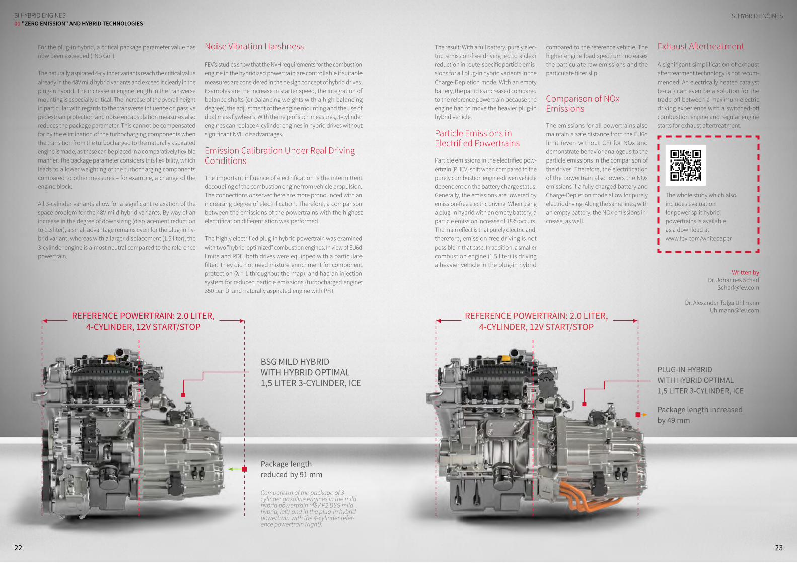
BSG MILD HYBRID WITH HYBRID OPTIMAL 1,5 LITER 3-CYLINDER, ICE
REFERENCE POWERTRAIN: 2.0 LITER, 4-CYLINDER, 12V START/STOP
Package length reduced by 91 mm
PLUG-IN HYBRID WITH HYBRID OPTIMAL 1,5 LITER 3-CYLINDER, ICE
Package length increased by 49 mm
REFERENCE POWERTRAIN: 2.0 LITER, 4-CYLINDER, 12V START/STOP
The whole study which also includes evaluation for power split hybrid powertrains is available as a download at www.fev.com/whitepaper
Comparison of the package of 3- cylinder gasoline engines in the mild hybrid powertrain (48V P2 BSG mild hybrid, left) and in the plug-in hybrid powertrain with the 4-cylinder refer-ence powertrain (right).

dIESEL HyBRId ENgINE
2524
dIESEL HyBRId ENgINE01 "ZERO EMISSION" AND HYBRID TECHNOLOGIES
FEV HECS ECOBRID WITH 48V HYBRIDIZATIONFEV ELECTRIFIES DIESEL
Over the next few years, a significant increase in 48V “mild hybrid” concepts is expected, since they offer considerable potential to reduce fuel consumption as well as pollutant emissions. At the same time, they are relatively easy to implement, since they do not require a complete redesign of the powertrain.
As part of a joint project with Valeo, FEV has equipped a D-segment test vehicle with a 48V electrical system, a belt-driven starter generator (BSG), and an electrically driven compressor (e-Compressor). The result: the optimi-zations contribute to a CO2 reduction potential of approximately 11% in the Worldwide Harmonized Light-Duty Vehicles Test Procedure (WLTP).
DIESEL HYBRID ENGINE Thanks to highly efficient exhaust gas aftertreatment systems, cur-rent diesel engines can comply with the lowest NOx emissions.
However, in very transient operating situ-ations – for instance, during strong accel-eration – a significant, short-term increase of NOx raw (engine-out) emissions can occur which to some extent reach the tailpipe. The reason for this is that the Exhaust Gas Recirculation (EGR) system and the turbocharger can only deliver the necessary EGR rate or the required charge pressure after a certain delay time (“turbo lag”).
Potential of Electric Components
Electrically driven components offer meaningful support; a belt-driven starter generator (BSG) can provide additional torque, allowing the engine to be oper-ated in a lower load range. In addition, an e-Compressor can generate the desired boost pressure with virtually no delay and independently of EGR, thus bridging the “turbo lag” of the turbocharger. As an additional measure, the exhaust gas tur-bocharger can alternatively be optimized with regard to higher efficiency or higher rated power.
HECS ECObrid Concept
The HECS ECObrid test vehicle uses the third generation of the FEV-HECS - a 1.6 liter 4-cylinder engine with single-stage su-percharging and combined high-pressure / low-pressure EGR. A 48V e-Compressor and a 48V BSG were also integrated. The complete electronic control system for the engine and the hybrid system are han-dled by a proprietary FEV model-based software, which was implemented on a dSpace MABX II Rapid Control Prototyping System (RCP).
The 48V e-Compressor is installed down-stream of the water-cooled charge air cool-er (WCAC) and the turbocharger, which has variable turbine geometry. This installation position leads to a reduced volumetric flow downstream of the e-Compressor, which improves transient behavior. The reduced flow also allows the selection of a smaller compressor with additional response time improvements. Intercooling also reduces the power requirements of the e-Com-pressor, since the compression takes place at a lower temperature level.
The test vehicle has a 12V/48V electrical system with 2 batteries. The 48V system consists of the BSG in “P0” position, a lith-ium-ion battery, and the e-Compressor. A bidirectional DC/DC converter is used to establish the connection to the 12V system, which was taken over from the production vehicle, which also powers the Diesel engine’s electric water pumps.
48V Components
The Valeo 48V BSG is based on a claw pole generator and is equipped with power electronics unit for boosting and motor control. The machine is air-cooled, which restricts the continuously available power to 4 kW, while a short-term peak power of up to 12 kW can be delivered. The BSG can deliver up to 160 Nm to the crankshaft via the belt gear ratio. The belt is tensioned for bidirectional power transmission with a double arm tensioner from Mubea.The air-cooled bidirectional DC/DC con-verter has a nominal power of 2.7 kW. It handles the supply of the 12V electrical system and is therefore only operated in
this case as a low-voltage regulator. The supply of the 48V electrical sys-
tem is realized through a circuit in the 48V
battery unit.
Air path of the HECS ECObrid
FOR A SHORT-TERM OVERBOOST, THE EGR RATE CAN BE FURTHER INCREASED, WHICH REDUCES NOx EMISSIONS
THROTTLE
E-COMPRESSOR
LP-EGR
EXHAUST GAS AFTERTREATMENT
TURBOCHARGER
HD-EGR
CHARGE AIR COOLER
M

2726
dIESEL HyBRId ENgINEdIESEL HyBRId ENgINE01 "ZERO EMISSION" AND HYBRID TECHNOLOGIES
The 48V prototype battery from Voltabox is based on a NMC/LTO cell chemistry and has a nominal capacity of 20 Ah. This comparatively high capacity enables a high degree of freedom for demonstrator applications and, in conjunction with air cooling, enables peak currents of up to 15 C. The battery module consists of 20 cells connected in series, re-sulting in an operational voltage of 44 to 48V in the relevant SoC area (SoC = State of Charge).
The Valeo 48V e-Compressor is driven by a switched reluctance motor and can be supplied with power of up to 6.5 kW. The low mass inertia leads to a very short response time of less than 150 ms.
Special Control Concept
The additional hybrid components of the HECS ECObrid require new control functions, which have been integrated in the software environment of the existing engine control unit.
The Powertrain (PT) area includes the various hybrid operating states and functions. These states can be used for any type of hybrid powertrain (Px, series, or power-split) and specify the high-priority driving modes (e.g. Hybrid or e-Drive) and the high-priority transient modes (for example, engine start or engine stop).
The software architecture includes functions for all common components of the 48V system, such as batteries, starter gen-erators, e-Compressors, DC/DC converters, and their interfaces.
Individual functions for com-ponent management, system coordination, and diagnostics are also included. The interfac-es of the individual hardware components are transferred to universal and hardware-in-dependent signals via input / output functions that are analogous to the basic func-tions for a diesel engine. This
allows easy exchange of components. In the case of a missing software feature, it can be added within the software module of the respective hardware component.
Hybrid mode is the most important mode of operation for mild hybrid applications. In this mode, the energy management module (EgyMgt) defines the battery power split for the 48V BSG and e-Compressor. The EgyMgt collects all power requests and prioritizes them according to the operating mode. This is how, for example, the BSG is prioritized for the engine start and launch assist.
The torque and speed setpoints are calculated in the modules of the BSG and the E-compressor, considering charge/discharge current, the limitations of the 48V strategy module, and torque request from the driver of the vehicle.
Powertrain of the FEV HECS ECObrid
Simulation Results
In order to demonstrate the potential of additional electrification to reduce NOx engine-out emissions and fuel con-sumption, simulations were carried out for example load steps, as well as for the future WLTP certification cycle.
In this manner, a distinction is made be-tween boost pressure build-up with an unchanged setpoint value and a transient
58 60 62 64 66 68 70Inta
ke m
anifo
ld p
ress
ure
[kPa
]
80
100
120
140
160
without e-Compressor - desiredwithout e-Compressor - actualwith e-Compressor- desiredwith e-Compressor - actualwith e-Compressor and Overboost - desiredwith e-Compressor and Overboost - actual
58 60 62 64 66 68 70
Soot
[g]
0
0.005
0.01
without e-Compressor with e-Compressorwith e-Compressor and recalibration
Time [s]58 60 62 64 66 68 70
NOx [
g]
0
0.05
0.1
0.15without e-Compressor with e-Compressorwith e-Compressor and recalibration
∆ NOx ~ 50 %∆ NOx ~ 40 %
Lorem ipsum
Control concept for the e-Compressor
Calculated CO2 reduction through 48V hybridization in WLTP
2L, D
-Seg
men
t
CO2 i
n W
LTP
/%
100% -5.1%
48 V,
BSG
-1.2%
48 V
e-
Com
pres
sor
-0.9%
Turb
ocha
rger
O
ptim
izat
ion
-4.2%
Dow
nsiz
ing
1.6L
THE ADDITIONAL HYBRID COMPONENTS REQUIRE NEW CONTROL FUNCTIONS, WHICH HAVE BEEN INTEGRATED IN THE SOFTWARE ENVIRON-MENT OF THE EXISTING ENGI-NE CONTROL UNIT
boost pressure increase (overboost). The boost pressure setpoint is achieved with virtually no delay thanks to the e-Com-pressor, whereby the EGR rate, which is calibrated for stationary operation, can be adjusted without an increase in soot emissions during the load step. For a short-term overboost, the EGR rate can be further increased, which leads to an additional soot-neutral reduction of NOx emissions.
Significantly Reduced CO2 Emissions
Overall, there is a CO2 reduction potential of around 11% in the WLTP. The majority, around 5%, is achieved via recuperation and electrical support of the BSG. How-ever, through various effects, the e-Com-pressor also delivers an additional CO2 re-duction of 2% when the required electrical
power is fully provided by recuperation. To begin with, the E-compressor reduces the charge-exchange work due to the rapid pressure build-up, and secondly, the larger exhaust-gas turbocharger (ATL) can be designed for a higher efficiency and lower back-pressure. Additionally, the larger turbocharger also enables an increase in specific engine output and thus a downsizing strategy, which leads to an additional CO2 reduction of over 4%.
Written by:Dr. Joschka Schaub
Dr. Michael [email protected]
DC
48V
12V
AC
GEAR12V BOARD-NETWORK
DCDC
STARTER E-COMPRESSOR
12V BATTERY
BSG
48V BATTERY

28 29
BATTERy AgINgBATTERy AgINg01 "ZERO EMISSION" AND HYBRID TECHNOLOGIES
LIFE-LONG AVAILABILITY OF THE BATTERY SYSTEM BMS ALGORITHM FOR STATE OF HEALTH DETERMINATION IN HYBRID AND ELECTRIC VEHICLES
With the increasing application of lithium-ion battery technology in the automotive industry, lifetime battery-aging behavior is an important topic for today’s xEV vehicle applications. Aging influences available battery capacity which is a crucial value for EV/PHEV applications, as well as battery internal resistance a crucial value for PHEV/HEV applications. Knowing the aging status (SOH, State of Health) of battery systems is important, since OEMs, workshops and even customers are interested in the SOH of the battery and some Battery Management System (BMS) functions need to be adjusted during operation to ensure the availability of the battery system throughout its lifetime.
BATTERY AGING
2928
Technical Challenges of Aging Prediction
Battery cell aging mechanisms are susceptible to two kinds of effects:
�Calendric aging (depending on SOC and temperature) � Cyclic aging (depending on depth of discharge and C-rate)
Both cases result in capacity fade and internal resistance increase, which is a direct drawback for system performance. To get sufficient information for the onboard aging model such
as capacity fading prediction and internal resistance prediction, exhaustive battery cell testing must be performed. These tests include storage and cycling under defined conditions for a long period of time.
Alternatively, accelerated aging can be applied – for example, using very high operating temperatures during tests for cyclic aging, resulting in faster aging and, therefore, time saved. How-ever, in this case, the extrapolated fuzziness of the results for estimating cell behavior over a lifetime under normal operating conditions might harm the accuracy of aging prediction over the full product life cycle, compared to the non-accelerated approach. In both cases (accelerated and non-accelerated aging analysis), unadapted static models might not be accu-rate enough to perform a reasonable aging prediction over a lifetime; they should be adapted online during operation when comparing measured and estimated battery parameters using real-time vehicle data.
FEV's Approach
FEV developed an online adaption concept without using com-plex aging prediction models. This offers a potential reduction in effort during battery cell testing, as well as in complexity of the BMS software and hardware. The concept is to determine SOH by monitoring fundamental BMS functions, calibrated at the beginning of life (SOC calculation and Power Prediction) of battery operation, since these BMS functionalities will be affected by aging: The system will not be capable of delivering the power given by the power prediction due to the increase in internal resistance, and SOC will then no longer be calculated correctly, assuming beginning-of-life battery capacity, which will be reduced. Monitoring is performed by way of a smart comparison of the operating data and related expected values under specific operating conditions. Furthermore, the BMS functions are adapted according to this comparison to ensure availability of the battery system over the course of its lifetime.
Outlook
This approach was designed to be a cost- and effort-optimized method of determination for SOH during a battery life cycle and to adapt relevant BMS functions accordingly. The goal is not to replace established methods, but may improve system behavior in development projects that are very cost and time sensitive.
Written by:Dr. Mirco Küpper
FEV’S ONLINE ADAPTION APPROACH MAY IMPROVE SYSTEM BEHAVIOR IN DEVELOPMENT PROJECTS THAT ARE VERY COST AND TIME SENSITIVE.
State-of-the-art approach to determine SOH during battery operation
Capacity fading prediction
Internal resistance prediction
Data processingState calculation
State of Health (SOH)
Comparison and adaption
∆DODCrate
SOCT
Long term test data
Real time vehicle data
∆Cstorage∆Cycle
∆Rstorage∆Rycle
SOC SOH
CapacityEstimation
Power Prediction
Phy/Dig Signals (measured)Phy/Dig SignalsPhy/Dig Signals (Feedback)
Signal and functional dependencies for SOH determination and function adaption
30
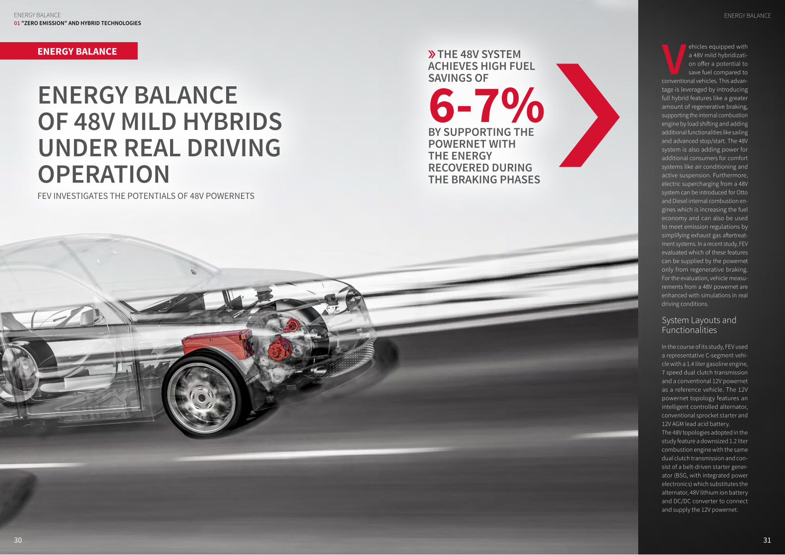
ENERGY BALANCE OF 48V MILD HYBRIDS UNDER REAL DRIVING OPERATION FEV INVESTIGATES THE POTENTIALS OF 48V POWERNETS
ENERGY BALANCE
ENERgy BALANCE01 "ZERO EMISSION" AND HYBRID TECHNOLOGIES
THE 48V SYSTEM ACHIEVES HIGH FUEL SAVINGS OF
6-7% BY SUPPORTING THE POWERNET WITH THE ENERGY RECOVERED DURING THE BRAKING PHASES
ENERgy BALANCE
31
V ehicles equipped with a 48V mild hybridizati-on offer a potential to save fuel compared to
conventional vehicles. This advan-tage is leveraged by introducing full hybrid features like a greater amount of regenerative braking, supporting the internal combustion engine by load shifting and adding additional functionalities like sailing and advanced stop/start. The 48V system is also adding power for additional consumers for comfort systems like air conditioning and active suspension. Furthermore, electric supercharging from a 48V system can be introduced for Otto and Diesel internal combustion en-gines which is increasing the fuel economy and can also be used to meet emission regulations by simplifying exhaust gas aftertreat-ment systems. In a recent study, FEV evaluated which of these features can be supplied by the powernet only from regenerative braking. For the evaluation, vehicle measu-rements from a 48V powernet are enhanced with simulations in real driving conditions.
System Layouts and Functionalities
In the course of its study, FEV used a representative C-segment vehi-cle with a 1.4 liter gasoline engine, 7 speed dual clutch transmission and a conventional 12V powernet as a reference vehicle. The 12V powernet topology features an intelligent controlled alternator, conventional sprocket starter and 12V AGM lead acid battery. The 48V topologies adopted in the study feature a downsized 1.2 liter combustion engine with the same dual clutch transmission and con-sist of a belt-driven starter gener-ator (BSG, with integrated power electronics) which substitutes the alternator, 48V lithium ion battery and DC/DC converter to connect and supply the 12V powernet.

32 33
ENERgy BALANCEENERgy BALANCE01 "ZERO EMISSION" AND HYBRID TECHNOLOGIES
THE NEED FOR ACTIVE CHARGE ENERGY, WHICH HAS TO BE SUPPLIED BY FUEL, IS DRASTICALLY INCREASING WITH HIGHER POWERNET LOAD
engine off sailing can also influence the driving experience negatively.
Average Power Distribution during FEV Cycle
The need for active charge energy, which has to be supplied by fuel, is drastically increasing with higher powernet load. At the same time it is restricting 48V function-alities, like BSG boost, since the energy is not free by recuperation and has to be generated from fuel along the engine and BSG efficiency. The amount of re-generative braking energy is also limited due to the effect of idling in stop phases and therefore not the full regeneration potential can be leveraged.
Fuel and CO2 Saving Potentials in the FEV Cycle
For the FEV Cycle, a real world driving cycle with average load profile was taken into consideration and compared to a reference case of a 12V powernet with stop/start functionality at 0 km/h. All cases were evaluated with (12V and 48V) balanced final SOC and an initial SOC for the 48V systems of 70%. The analyzed real world driving cycle consists of 90 km in urban, extra-urban and highway driving with an average speed of 50 km/h and a maximum speed of 121 km/h. During
this drive cycle the 48V system achieves high fuel savings of 6-7% by supporting the powernet with the energy recovered during the braking phases. Due to the high powernet load, very limited energy is available for boosting, resulting in a large share of engine operation above optimal conditions. Due to the highly dynamic and demanding driving cycle, the eCharger is extensively used. This component increas-es engine low end torque and avoids turbo lag enabling combined “downsizing” and “downspeeding” with a resulting benefit
in term of fuel consumption of 1-2 gCO2/km. Sailing functionality (with engine off) during deceleration and downhill phases enables a further fuel consumption benefit of 4%. However, this potential is highly depending on the driver’s anticipation.
Author:Dr. Andreas Balazs
� 1.4l 103 kW engine with TC
� Pb 12V Bat. � 14V Alternator
(2.4 kW) � Stop/Start: 0 km/h � Intelligent Alter-
nator � No Boosting
� 1.4l 103 kW engine with TC
� Pb 12V Bat. � 14V Alternator
(2.4 kW) � Stop/Start: 7 km/h � Intelligent
Alternator � No Boosting
� 1.2l 88 kW engine with TC
� Pb 12V + NMC 48V Bat.
� 48V BSG (14 kW) � Stop/Start:
20 km/h � Max. energy
recovery � No Boosting
� 1.2l 88 kW engine with TC
� Pb 12V + NMC 48V Bat.
� 48V BSG (14 kW) � Stop/Start:
20 km/h � Max. energy
recovery � Boosting with BSG
� 1.2l 103 kW engine with lager TC and 48V eC
� Pb 12V + NMC 48V Bat.
� 48V BSG (14 kW) � Stop/Start:
20 km/h � Max. energy
recovery � Boosting with
BSG / eC
� 1.2l 103 kW engine with lager TC and 48V eC
� Pb 12V + NMC 48V Bat.
� 48V BSG (14 kW) � Engine off sailing � Max. energy
recovery � Boosting with
BSG / eC
145.0100
120
140
160
144.2 135.6 135.0 133.5 128.0
140.0100
120
140
160
139.5 133.9 131.5 130.3 128.4
110.090
100
110
120
109.0 104.2 103.0 102.3 102.3
FEV
cycl
e / (
gCO
2/km
WLT
P - T
MH
/ (gC
O2/
km)
NED
C/ (
gCO
2/km
)
- 0.6%
- 0.4%
- 0.9%
- 6.5%
- 4.4%
- 5.3%
- 6.9%
- 6.1%
- 6.4%
- 7.9%
- 6.9%
- 7.0%
- 11.7%
- 8.3%
- 7.0%
Average Scatterband
CO2 emissions along NEDC, WLTP and FEV Cycle for balanced SOCs
Powernet consumption of C-segment vehicle (FEV database)
Indoor FanEPSLightsRear window heaterSeat heaterStarterWindow wiperOther
1,132
546
334
1,200
1,000
800
600
400
200
1,100
900
700
500
300
100
0
36681
386
2116
6
80
112
821720
480
Pow
erne
t loa
d / W
High load scenario Normal load scenario
Average power distribution during FEV Cycle
48V Starter Generator
48V Electrical charger
48V Mild Hybrid
48V High Performance Powernet
48V
Enabling of further electrification and sufficient energy supply of
� Electrical A/C Compressor � Active roll stabilization � Electrical Power Steering � Electrical heated catalyst � PTC heater, Electrical pumps, Cooling fans
Increased potential by powerful electric machine � Increased recuperation potential � Electrical boosting � Advanced fast starting S&S system
Additional Hybrid functions � Electrical creeping � Engine off coasting � Load point shift
Assist of ICE by electrical charger to avoid turbo-lag of downsized engines
� Higher low end torque � Reduction of back pressure
48V system – new features and functionalities
1.400
1.000
600
1.200
800
400
200
0NEDC WLTC FEV
Cycle
420 420
620
Pow
erne
t loa
d / W
FEV set up a comprehensive database containing detailed powernet measure-ments for different drive cycles, including real world driving.
The powernet consumption was varied according to varying loads. In the high load scenario, all selectable consumers were switched on at maximum stage. During the normal load scenario, just low beam lights, infotainment, radio and automatic air conditioning were acti-vated. Average powernet consumption is between 0.5 and 1.2 kW (depending on environmental conditions and user profile). However peak consumption can be 2 to 3 times higher.
Starting from minimum powernet load, fuel sav-ing slightly increases from 6% up to7 %. This improvement is affected by two aspects: On the one hand stop/start func-tion of the conventional vehicle is limited due to
less energy recovery and SOC constraints of the lead acid battery. On the other hand electrical charging using the BSG can profit from intelligent load shift operation. In contrast high load scenarios lead to lower benefits of the hybridization due to further limitation of the 48V function-alities. At the same time the limitation of functionalities like advanced stop/start or
Various 48V topologies with different functionalities were considered. Starting from a reference baseline with a con-ventional powernet and stop/start at 0 km/h, this study analyses the impact of expanding a stop/start system up to engine off sailing as well as various boost-ing strategies and their corresponding electrical energy demand.
Sensitivity Analysis: Powernet Consumption
Identification of powernet consumption in real driving is very complex due to a large range of applications, vehicle vari-ants and the influence of customer be-havior. Based on a systematic approach,

3534
The growth of the global popu-lation, along with a dispropor-tionate increase in transporta-tion capacity, represents one
of the biggest challenges with regard to sustainable mobility concepts. In parti-cular, increasing urbanization and the simultaneous intensification of the debate regarding the reduction of pollutant emis-sions in metropolitan areas is leading to the electrification of commercial vehicle powertrains. For lightweight transport vehicles, such as courier service and mail distribution vehicles, there are already
large numbers of corresponding, elec-tric-only solutions, in large numbers, on the market. It is to be expected that this technology will also find its way into the heavier vehicle classes.
The combination of electric motors with an additional range extender represents an obvious solution for the typical me-dium-duty commercial vehicle segment, which also considers changing daily re-quirements with regard to the delivery routes to be served. A serial arrangement of the drive sources already offers signifi-cant potential, and can be implemented fairly easily.
Computational simulation
As part of a simulation study based on a purely electric vehicle, FEV has examined various drives and has assessed them with regard to consumption potential and operating costs. The base vehicle was defined as a typical, two-axle distribution vehicle with an authorized total weight of 12 tons. To dimension the purely electric drive, fleet data from a shipping company, located in the Cologne-Aachen area were used, which indicated a daily de-
livery route of about 100 km, corresponding to about 50% of all journeys over a period of 10 days. The battery capacity for all hybrid drives was then calculated, resulting in a total capacity of 100 kWh in the selected driving cycle, considering 50% of the maximum payload and a usable energy content of 75% of
the battery. A larger battery for a range of 200 km in pure electric operation was also investigated. Due to the torque characteristics of electric motors, an electric power of 150 kW was selected.
Range Extender Concepts
In addition to a 7.5-liter 6-cylinder die-sel engine with a rated output of 180 kW, representing a typical conventional drive unit in this vehicle class, low-cost passenger car engines were also chosen as possible range extenders, including a 2-liter diesel engine and a 1.8-liter otto-motor with 130 kW nominal power. A fuel cell system with 100 kW electric power was also considered. Different exhaust gas aftertreatment systems and tank sizes were applied to the engines inves-tigated, and the corresponding weights were taken into account. All systems were investigated from a design perspective with regard to packaging feasibility by means of existing data from a typical vehicle. The batteries were placed in the frame for safety reasons. As an electric drive, two motors on the rear axle with the above mentioned total power of 150 kW were considered.
RANgE ExTENdER SySTEmSRANgE ExTENdER SySTEmS
HIGH FLEXIBILITY, REDUCED OPERATING COSTSRANGE EXTENDER SYSTEMS FOR E-DRIVES FOR MEDIUM-HEAVY TRANSPORT VEHICLES
As part of its search for an optimized drive configuration for medium-heavy duty transport vehicles, FEV investigated the potential of serial hybrid systems compared to conventional and pure electric drives. The results show that, even using today’s realistic cost scenarios, the operating costs for serial hybrid solutions can be reduced compared to conventional drives. In order to achieve this, the energy strorage and the drive sources must be dimensioned to suite the requirements and optimized with a view toward the typical driving profile. Such computational investigations are also a tried and tested means of determining the most suitable combination of drive solutions for a specific vehicle fleet based on requirement profiles and fleet data. The acquisition costs of such systems will always have to be assessed against the background of the current political discussions and the dynamically changing market prices.
RANGE EXTENDER SYSTEMS
01 "ZERO EMISSION" AND HYBRID TECHNOLOGIES
EVEN WITH CURRENTLY REALI-STIC COST SCENARIOS, THE OPERATING COSTS FOR SERIAL HYBRID SOLUTIONS CAN BE RE-DUCED COMPARED TO CONVENTI-ONAL DRIVES
2.0 LITER DIESEL ENGINE WITH CLOSED COUPLED
EXHAUST AFTER- TREATMENT
BATTERY PACKS
GENERATOR
ELECTRICMACHINES
ADBLUE TANK
FUEL TANK

3736
Power and Fuel Consumption
Using a simulation tool that is based on a model library, the power and fuel consumption of the vehicle for the dif-ferent drive variants are calculated into the Worldwide Harmonized Vehicle Cycle (WHVC), as well as the Urban Delivery Cycle (UDC). The UDC was established in various studies and also takes height pro-
files into account. The operation strategy foresees the initial provision of the power required by the battery until the defined minimum charge status is achieved – in this case, 20% of the full charge. From that point on, the charge status for recharging the battery is kept more or less constant by the starting of the combustion engine. The control of engine operation prevents high specific consumptions and uses the engine operating points that provide the best operating area for a specific perfor-mance. Compared to a layout with only
one operating point, this operation with a changing rotational speed is acoustically much more pleasant for the driver. In WHVC, the Diesel range extenders showed a consumption reduction of 2%, respectively 7% in charge sustaining mode, compared to a strictly conventional drive. Due to the higher specific consump-tion, consumption increases by 18% when a gasoline engine is used as an additional drive source. In this context, it should
be noted that the consumption of the conventional drive with an additional weight equivalent to the electrical com-ponents increases by around 7% in WHVC. If this is used as a ba-
sis, the consumption of the hybrid systems is, accordingly, more cost-effective. The comparison with the results in the Urban Delivery Cycle, which are characterized by a lower share of high speeds, more fre-quent acceleration and braking processes, as well as a height profile, shows a higher basic consumption, but also offers more significant savings potential in hybrid operation. Overall, the power to be used for the cycle is less than what electric-only operation shows.
Calculation of Costs for Daily Operation
Generally speaking, the concepts must be assessed in real operation, using the daily driven distance, with regard to the running costs and the power requirements of the vehicle. As part of the FEV analysis, the pure power costs are used, but initial costs, depreciation and wear costs for the systems are not taken into account. In order to take the currently prevailing uncertainty with regard to future energy costs into consideration, the costs for fuel and power are reflected in two scenarios. In the first scenario, moderate fuel prices based on average prices between 2011 and 2016 are used, while the power price is based on the household price. In the second scenario, the maximum fuel price from the period considered is used, while a reduced power price for industrial clients is applied as an alternating classification of fleet operators can be predicted with an increasing number of electrified vehicles.
IN WHVC, THE DIESEL RANGE EXTENDERS SHOWED A CONSUMPTION REDUCTION OF 2% RESPECTIVELY 7% IN CHARGE SUSTAINING MODE
RANgE ExTENdER SySTEmSRANgE ExTENdER SySTEmS01 "ZERO EMISSION" AND HYBRID TECHNOLOGIES
Fuel and power consumption of powertrain variants
Fuel/Power Consumption
Powertrain UnitWHVC UDC
absolute relative absolute relative
Conventional l/100 km 21.5 100% 22.2 100%
Serial Hybrid Systems
with 7.5 Liter Diesel l/100 km 21.1 98% 19.6 88%
with 2.0 Liter Diesel l/100 km 20 93% 18.5 83%
with 1.8 Liter Gasoline l/100 km 25.3 118% 22.6 102%
with Fuel Cell kg/100 km (H2) 6 5.1
Electric-Only System
100 km Range kWh/100 km 71.5 62.5
200 km Range kWh/100 km 74.8 64.8
Results
The costs for the conventional, or elec-tric-only, drive increase linearly with the distance driven, as per the respective cost scenarios. This changes upon switching to serial hybrid operation: starting at a daily distance driven of 100 km, the cost gradient decreases in accordance with the calculated fuel consumption and power costs.
Within the delivery distance considered (that of up to 200 km per day), the operation costs for serial hybrid operation with Diesel engines are always cheaper than those of a conventional engine. With gasoline engines, however, due to the higher power prices and the higher specific consump-tion, there is also a price disadvantage in scenario 1. The operation costs for a fuel cell, due to high hydrogen prices – which were kept constant at EUR 7.70/kg in both scenarios – are higher than basic operation, starting at 125 km, respectively 150 km.
Written by:Stefan Wedowski
Johannes [email protected]
Christopher [email protected]
Serial drive concept for medium-duty transport vehicles
FRONT AXLE REAR AXLE
HV ACHV DCLV DC
LOW VOLTAGE LOADS
LITHIUM ION BATTERY
RANGE EXTENDER SYSTEM(ICE OR FUEL CELL BASED)
24 VBATTERY
DC
DCDC
DC
ACAC
EM 1
EM 2
Operation costs for daily distance based on WHVC
Szenario 1
Diesel / (€/l) 1.07
Gasoline / (€/l) 1.19
Electric Energy / (€/l) 0.24
Hydrogen / (€/l) 7.70
Days of operation per year 250
Szenario 2
Diesel / (€/l) 1.22
Gasoline / (€/l) 1.35
Electric Energy / (€/l) 0.17
Hydrogen / (€/l) 7.70
Days of operation per year 250
€5
€15
€25
€35
€45
€55
50 100 150 200
Daily driving distance / km
ConventionalREEV (7.5 D)REEV (2.0 D)REEV (1.8 G)BEV 200FCEV
Scenario 2€5
€15
€25
€35
€45
€55
50 100 150 200
Daily
cos
t / €
Daily driving distance / km
Scenario 1

In conventionally powered vehicles, a portion of the excess radiated heat energy form the internal combusti-on engine is used to heat the passenger compartment. In electric vehicles, this heat source is not available due
to their higher tank-to-wheel effi-ciency. Instead, an additional he-ater is necessary that is powered by the battery. The cruising range of electric cars is reduced by 50% when the heater is turned on as a result. Increasing the efficiency of the vehicle or the passenger com-partment air conditioning system is a major challenge on the road to making electric cars competitive for everyday use.
In a recent study, FEV focused on the potential for energy savings from heating surfaces in the immediate vicinity of the driver. The heating system was installed in an electrical test vehicle and consists of an elec-tric PTC air heater and electrically operated, radiating surfaces in the passenger compartment. Extensive measurements were conducted on the test vehicle in a climatic cham-ber and the energy consumption of the heating systems was recorded. By comparing the energy consump-tion in both heating processes, an energy savings potential of as high as 9% was identified..
38 39
HEATINg CONCEPTSHEATINg CONCEPTS02 VEHICLE DEVELOPMENT
HEATING CONCEPTS
FEV EVALUATES CABIN HEATING SYSTEM THAT COMBINES CONVECTIVE AIR HEATING AND RADIANT HEATING SURFACES INCREASED RANGE AND IMPROVED COMFORT FOR ELECTRIC VEHICLES

40 41
HEATINg CONCEPTSHEATINg CONCEPTS02 VEHICLE DEVELOPMENT
Operating Temperature
The heating system uses both convec-tion and heat radiation to heat the cabin. Therefore, measuring the air temperature alone is insufficient. In order to adequately consider the interaction of both of the heat transfer mechanisms, another method for evaluation of passenger compartment heating must be used. One good possibility is the so-called operating temperature. The operating temperature weights the heat transfer coefficients of convective and radiative heat transfer. For this measurement, a dedicated sensor for measuring the ra-diant heat was developed as a first pro-totype. Experience from the construction sector shows that using the operating temperature instead of the air tempera-ture in the control of a room’s heating system reduces energy consumption and improves thermal comfort.
Temperature Measurement
In order to assess passenger compart-ment heating, various temperature mea-surement points were determined inside the passenger compartment. Since the aim of the new measurement method was not to evaluate the heating perfor-mance but to compare the two heating methods, obtaining the temperatures at the front seats was sufficient. Tempera-tures were taken at head and foot levels. 8 temperature measuring points were set up in the test vehicle; 4 measuring
points were installed in the driver and the passenger sides, respectively. 2 of the 4 measuring points were attached to the headrests on each side.
A self-developed flat sensor with a 3 cm edge length was used for detecting the operating temperature at foot level. This is because the heat-radiating surfaces were installed in the foot wells of the driv-er and the passenger sides. The average cabin temperature can be calculated by averaging the air temperatures at head level and the operating temperatures at the foot level.
Heating System
The conventional heating system, con-sisting of a pure electric air heater and a fan, was extended by electrically operated, heat-radiating surfaces in the vehicle's foot wells.
A literature study on radiant heating for buildings revealed that radiant heaters can demonstrate energy consumption that is about 10% lower than convective heating systems. According to the study, the air temperature can be reduced by 5 K without adverse effects on the perception of thermal comfort. Additionally, heat loss-es due to air exchange are reduced. The proportion of the heating energy bound to a transport medium (air flow) is smaller when applying additional radiant heating systems. Under cold ambient conditions in a vehi-cle, the feet and legs should be warmer than other parts of the body – which is why heat-radiating surfaces were installed near the feet and legs. The foot wells of the test vehicle were suitable because their walls offered sufficient space for installation. In both the original and the modified heat-ing systems, cold ambient air enters the HVAC-system. The temperature of the air is increased by the PTC heater. In the modified vehicle with the additional radiant heating system, the heater power was reduced, resulting in a lower increase in the air temperature. The heating power of the two heating systems was deter-mined by measuring the temperature at both the head and foot levels.
Measurement Procedure
A series of measurements was conduct-ed in a climatic chamber at an ambient temperature of -10 °C. The outlet of the air flow in all measurements was set to feet only. The test setup was not influenced
PFan THead
TFeet
QHeating
by either wind speed or solar radiation. The test vehicle was heated for about 25 minutes. To compare the thermal output of all test configurations, three different temperature measurement locations were considered – at foot level, at head height, and the average temperature of the pas-senger compartment.
Average Passenger Compartment Temperatures and Energy-saving PotentialAt the average passenger compartment temperature, the results showed that the PTC heating output was either too high (measurement combination 1) or too low (measurement combination 2). There-fore, the resulting temperature profiles from measurements Combination 1 and Combination 2 were interpolated, thus providing an estimate of the tempera-ture profile for a measurement with the corresponding PTC heating power. The power consumption of the interpolated measurement was calculated accord-ingly, averaging the power consumption of measurements Comb. I and Comb. II. Using radiative heating, only 90.7% of the heating energy is necessary to achieve heating performance equal to that of a conventional system. Since the results are based on an interpolation, the po-tential for energy savings is not justified physically. It can be used as a prediction of energy-saving potential.
Meas. Ptot PPTC Prad Pfan AirData [kW] [kW] [W] [W] Oulett
Ref. I 3.3 3.2 0 100 Feet
Comb. I 3.5 3.2 200 100 Feet
Comb. II 2.7 2.4 200 100 Feet
Measurements taken:- Ref. I: Maximum PTC power of 3.2 kW and 0.1 kW of fan power
- Comb. I: Same as Ref. I with an additional 0.2 kW radiation heating power- Comb. II: PTC power of 2.4 kW, 0.1 kW fan power and 0.2 kW radiation heating power
Schematic view of the conventional (left) and new (right) heating system
QRadiation
Subjective Impression of the Radiative Heating System
During winter in Alsdorf, Germany, sub-jective tests were conducted in order to adjust the settings of the various heating systems and to check the temperature sensors. During these tests, the radiant heating system was subjectively assessed. The ambient temperature during the test was 3°C, providing realistic conditions for the vehicle heating. A human subject was placed in the front seat of the equipped vehicle while the heating system was op-erated. The test subject’s clothing was appropriate for the winter conditions, consisting of jeans, a winter jacket and low shoes. Approximately two minutes after the start of the heating process, the radiant heat was sensed by the subject.
The air temperature was lower than that of the heat radiating surfaces. In gen-eral, the radiant heat was perceived as pleasant. The test subject deliberately touched the radiating surfaces with his legs during the test, thereby improving thermal comfort. Due to the proximity of the radiant surfaces to the legs, this posture could be taken by the driver while driving the car. The test subject reported a positive overall impression of the radiant heating. Objective measurements, even those employing a thermal mannequin, do not consider behavioral responses such as those described above.
Written byDavid Hemkemeyer
Daniel Perak [email protected]
Klaus [email protected]
Ralf [email protected]
Tem
pera
ture
/ °C
0 105 15 20 25 30
30
10
20
0
25
5
15
-5
-10
Time / min
Combination ICombination IIReference IIInterpolation Combination I andCombination II

42 43
MAY
03.05.-04.05.201709.05.-11.05.201716.05.-18.05.201717.05.-19.05.201718.05.201724.05.-26.05.201730.05.-31.05.2017
15. ATZ - Karrosseriebautage Hamburg2017 International VI-grade Users ConferenceInteger & AdBlue® Forum ChinaTorsional Vibration Symposium SalzburgFEV Diesel DayJSAE Automotive Engineering Exposition 2017 YokohamaAutomotive Engineering Expo (AEE)
Hamburg, GermanyTurin, ItalyBeijing, ChinaSalzburg, AustriaBeijing, ChinaYokohama, JapanNürnberg, Germany
JUNE
06.06.-08.06.201707.06.-08.06.2017 20.06.-22.06.201720.06.-21.06.2017 20.06.-21.06.2017 20.06.-22.06.201727.06.-28.06.201727.06.-28.06.2017
Electric & Hybrid Marine - World Expo 2017International Conference and Exhibition - SIA Powertrain 20175th TMFB International Conference8th Munich International Symposium on Suspension - chassis.tech plus 20176th European Ground System Architecture Workshop - ESA/ESOC**Automotive Testing Expo Stuttgart 20177. VDI-Fachtagung - Ventiltrieb und Zylinderkopf 201721st International Congress on Advances in Automotive Electronics
Amsterdam, NetherlandsVersailles, France Aachen, GermanyMunich, Germany Darmstadt, Germany Stuttgart, GermanyWürzburg, GermanyLudwigsburg, Germany
JOIN OUR UPCOMING CONFERENCE
DIESELPOWERTRAINS 3.0
11TH & 12TH JULY 2017, LUDWIGSBURG, STUTTGART
For more information please visit: fev-events.com
JOIN OUR UPCOMING CONFERENCE
ZERO CO2
MOBILITY9th - 10th NOVEMBER 2017,
HOTEL PULLMANN QUELLENHOF, AACHEN
UPCOMING EVENTS
MEET MORE THAN 4,200 FEV EXPERTS IN OUR INTERNATIONAL
ENGINEERING AND SERVICE CENTERS
TranslationsEVS Translations
IMPRINT
Spectrumissue 01/2017 (Number: 61)
EditorialPatrick Gälweiler, FEV
LayoutEmrach Achmetoglou, FEV Consulting
Has your address changed? Do you know a colleague who would also like to receive future issues of the SPECTRUM? Send the name of your company, person’s name, and complete mailing address by email to: [email protected]
READER SERVICE

01 AUS FORSCHUNG UND ENTWICKLUNGHEATINg CONCEPTS
Contact
FEV Europe GmbHNeuenhofstraße 18152078 AachenGermany
Phone +49 241 5689-0Fax +49 241 5689-119 [email protected]
FEV North America, Inc.4554 Glenmeade Lane Auburn Hills, MI 48326-1766 ∙ USA Phone +1 248 373-6000Fax +1 248 373-8084
FEV Beijing Vehicle Development Center168 Huada Road, Yanjiao High-Tech Zone065201 Sanhe City Langfang Hebei Province ∙China Phone +86 10 80 84 11 68
FEV India Pvt, Ltd.Technical Center IndiaA-21, Talegaon MIDCTal Maval District ∙ Pune-410 507 ∙ India Phone +91 2114 666 - 000 [email protected]