zimmer trabecular metal tibial coneprod-...trabecular metal cone surgical technique 3 in significant...
TRANSCRIPT

Provides structural support in areas of bone loss
Zimmer®
Trabecular Metal™ Tibial Cone
Surgical Technique

Trabecular Metal™ Cone Surgical Technique 1
Zimmer® Trabecular Metal™ Tibial Cone Surgical Technique
Table of Contents
Overview 2
Tibial Preparation 4Tibial Resection/Cone Preparation 4
Base Plate/Stem Extension Selection and Initial Trialing 5
Final Positioning of Cone in the Tibia 7
Implanting Components 8

Trabecular Metal™ Cone Surgical Technique2
OverviewThe objective of using Trabecular Metal Cemented Cone implants is to achieve stability of the construct within the proximal tibia while allowing the compressive forces to physiologically load the surrounding bone (Fig. 1).
The cone that is selected must offer the ability to:
Fig 1
• Reinforce the inner endoseal tibial cavity while maintaining viable bone
• Allow the stem of the selected NexGen® Tibial Base Plate and the selected stem extension to be inserted through the cone and positioned into the intramedullary tibial canal
• Allow the entire assembled and seated construct (cone augment tibial base plate/stem extension) to provide appropriate coverage of the proximal tibial surface
Significant tibial bone defects may be located near, or away from the center of the tibia (Fig. 2). Therefore, both full and stepped tibial cones should be considered. Stepped cones may offer an advantage when one compartment of the tibia exhibits significant bone loss, while the opposite compartment has less damage.
Note: These cones are limited for use with NexGen Complete Knee Solution, Legacy® LCCK and Rotating Hinge Knee. When used with the NexGen Complete Knee Solution - Rotating Hinge Knee System, the Trabecular Metal Tibial Cone Augments are for cemented use only. When used with the NexGen Complete Knee Solution - Legacy Constrained Condylar Knee System, the Trabecular Metal Tibial Cone Augments and Trabecular Metal Femoral Cone Augments are for cementless or cemented use.

Trabecular Metal™ Cone Surgical Technique 3
In significant revision situations, positioning of the tibial base plate is often dictated by the interaction of the stem extension (attached to the base plate) and the intramedullary canal. Therefore, use of offset and/or straight stem extensions should be considered during the initial cone selection process. The cone will allow some A/P and M/L freedom of the stem extension, which varies depending upon:
• Size of the cone selected
• Diameter of the stem extension
• Location of the cone relative to the center of the IM canal
The tibia must be prepared for the assembled combination of the tibial base plate, the stem extension and the selected cone augment. Repeated trialing of the various possible combinations help to simultaneously optimize:
• Fit of the cone in the defect area of the tibial cavity
• Coverage of the tibial surface
• Fit of the stem extension in the canal
• Preservation of good proximal tibial bone
Some compromises will likely be necessary to achieve stability of the entire construct.
Fig 2
Full ConeStepped Cone, 15mm/30mmStepped Cone, 30mm/15mm

Trabecular Metal™ Cone Surgical Technique4
Tibial Preparation
Tibial Resection/Cone Preparation
Initial Proximal Tibial ResectionReam the tibia to the appropriate diameter where stability of the reamer is gained. Remove the reamer and replace with the Stem Provisional Adapter to which has been attached a Straight Stem Extension Provisional of the diameter of the last reamer used.
Initial Cone SelectionSelect a Tibial Cone Augment Provisional component that approximates the size and depth of the defect and insert it over the reamer. Inverting the cone augment provisional will best simulate the proximal void that the selected cone will accommodate (Fig. 4). This also will provide an estimate of the A/P and M/L position of the defect, relative to the center of the IM canal.
Fig 3
Fig 4
Cut the top of the tibia to the angle recommended for the base plate using the appropriate IM Tibial Boom and appropriate Tibial Cutting Guide. Remove the Tibial Cutting Guides, leaving the reamer protruding from the tibia (Fig. 3).

Trabecular Metal™ Cone Surgical Technique 5
Base Plate/Stem Extension Selection and Initial Trialing
Stem Extension Provisional SelectionThe NexGen system has several choices of stem extension components, in sharp fluted (press-fit) and cemented designs, and in various lengths (Fig. 5). If the defect is central, a straight stem extension may be an optimal choice. An offset stem extension will allow up to 4.5mm translation in any direction and may offer an option when the defect is biased more toward the cortex (usually medial). Additionally, the distal opening of the cone will allow some translation of the stem extension within the cone. The amount of translation varies depending upon the size of cone and the diameter of stem extension selected (Fig. 6).
Note: the NexGen Rotating Hinge Knee tibial base plate will normally require use of a straight stem extension since the stem of the NexGen Rotating Hinge Knee tibial base plate is longer than those of other NexGen tibial base plates.
Tibial Base Plate Provisional Selection Approximate the “best fit” tibial base plate by using the Provisional Tibial Sizing Plates. Confirm your selection by assembling the selected Stem Extension Provisional to the Provisional Stemmed Tibial Base Plate and defining the suitability of the selection. The ability to achieve proper coverage of the proximal tibia and proper external tibial rotational alignment must be considered (Fig. 7).
Fig 5
Fig 6
Fig 7

Trabecular Metal™ Cone Surgical Technique6
Tibial/Femoral Size RelationshipsSince use of Cone implants in the tibia is generally only considered when significant loss of proximal tibial bone has been encountered, the normal tibiofemoral sizing relationships may no longer exist. Frequently the size of the tibia is significantly smaller than the patient’s tibia in the index procedure. It may be possible to “size up” the tibia by use of a tapered proximal tibial augment under the base plate. This will move the location of the base plate (and therefore, tibial joint line) proximally while at the same time, allow use of the next size larger tibial component (Fig. 8). In the NexGen Knee System, this also allows use of the next size larger femoral component, which has a larger A/P dimension, tightening the Flexion Gap. At a minimum, it must be confirmed that the potential tibial base plate and intended LCCK or Rotating Hinge Knee femoral component selected will match the available articulation surface choices of the implant system.
Initial Trial Positioning of the AssemblyInsert the Cone Provisional into the void of the tibia (Fig. 9). It is intended to independently position the cone provisional so that the wedge shape can subside to a point where it can carry compressive loads. It should be anticipated that the final seating position of the cone will be below the cut surface of the tibia. Attempt to insert the tibial base plate and stem extension into the IM canal of the tibia. Ascertain if a compromise in one of the above components is necessary to achieve stability while minimizing bone loss and providing appropriate
Fig 8 Fig 9
tibial coverage and orientation. It is important to make the decision to compromise one of the above selected components in favor of optimizing stability of the entire construct. If necessary, repeat initial trialing using different choices of cones, stem extensions, tapered augments and base plate provisional components until it can be ascertained that the entire construct can be properly inserted and oriented.
Note: By design, the cone implant will fit similarly to or slightly tighter than the provisional implant.
Trabecular Metal™ Cone Surgical Technique 7
Fig 10
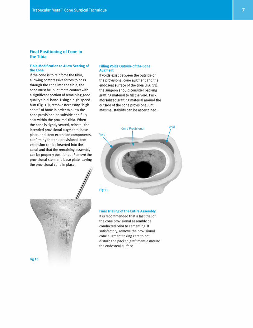
Final Positioning of Cone in the Tibia
Tibia Modification to Allow Seating of the ConeIf the cone is to reinforce the tibia, allowing compressive forces to pass through the cone into the tibia, the cone must be in intimate contact with a significant portion of remaining good quality tibial bone. Using a high-speed burr (Fig. 10), remove necessary “high spots” of bone in order to allow the cone provisional to subside and fully seat within the proximal tibia. When the cone is tightly seated, reinstall the intended provisional augments, base plate, and stem extension components, confirming that the provisional stem extension can be inserted into the canal and that the remaining assembly can be properly positioned. Remove the provisional stem and base plate leaving the provisional cone in place.
Filling Voids Outside of the Cone AugmentIf voids exist between the outside of the provisional cone augment and the endoseal surface of the tibia (Fig. 11), the surgeon should consider packing grafting material to fill the void. Pack morsalized grafting material around the outside of the cone provisional until maximal stability can be ascertained.
Final Trialing of the Entire AssemblyIt is recommended that a last trial of the cone provisional assembly be conducted prior to cementing. If satisfactory, remove the provisional cone augment taking care to not disturb the packed graft mantle around the endosteal surface.
Fig 11
Void
Cone Provisional Void

Trabecular Metal™ Cone Surgical Technique8
Implanting Components
Inserting the Cone Augment ImplantApply bone cement (Rotating Hinge Knee or LCCK) to the outside periphery of the Cone implant and insert into the prepared tibial void (Fig. 12). Alternatively, if press-fitting (LCCK only) insert cone implant directly into prepared tibial void. It should be noted that although the cone augment provisional and implant are the same dimension, the surface of the cone implant is porous and therefore a higher friction fit than the provisional component. The cone impactor can be used to guide the cone into position using gentle mallet taps (Fig. 13). If utilizing cemented technique, remove excess bone cement.
Note: If excessive force is used to seat the implant, tibial fracture may occur. Additional cancellous bone should be removed to allow implant insertion.
Cementing the Tibial Base Plate and Stem ImplantsProperly assemble the stem extension and tibial base plate implants in the proper orientation decided from previous trailing. Form bone cement on the bottom of the tibial base plate so that it will fill the interior of the cone implant and also fills the internal cavity of the tibia (Fig. 14). Insert the base plate assembly into the cone augment. Verify correct rotational alignment and impact the implant assembly into position and remove excess bone cement (Fig. 15).
Fig 14
Fig 13
Fig 12
Fig 15


Contact your Zimmer representative or visit us at www.zimmer.com
Trabecular Metal Cone Implants
Product No. Description
00-5450-001-00 Full Implant Kit
00-5450-048-01 TM Cone Size 48-15mm Full, Extra Small
00-5450-052-01 TM Cone Size 52-15mm Full, Small
00-5450-059-01 TM Cone Size 59-15mm Full, Medium
00-5450-059-05 TM Cone Size 59-30mm Full, Medium
00-5450-059-20 TM Cone Size 59 Stepped, Medium, Height 30mm/15mm
00-5450-059-21 TM Cone Size 59 Stepped, Medium, Height 15mm/30mm
00-5450-067-01 TM Cone Size 67-15mm Full, Large
00-5450-067-05 TM Cone Size 67-30mm Full, Large
00-5450-067-20 TM Cone Size 67 Stepped, Large, Height 30mm/15mm
00-5450-067-21 TM Cone Size 67 Stepped, Large, Height 15mm/30mm
Trabecular Metal Cone Provisionals and Instruments
Product No. Description
00-5979-011-00 Full Instrument Provisional Kit
00-5451-048-01 TM Cone Prov. Size 48-15mm Full, Extra Small
00-5451-052-01 TM Cone Prov. Size 52-15mm Full, Small
00-5451-059-01 TM Cone Prov. Size 59-15mm Full, Medium
00-5451-059-05 TM Cone Prov. Size 59-30mm Full, Medium
00-5451-059-20 TM Cone Prov. Size 59 Stepped, Medium, Height 30mm/15mm
00-5451-059-21 TM Cone Prov. Size 59 Stepped, Medium, Height 15mm/30mm
00-5451-067-01 TM Cone Prov. Size 67-15mm Full, Large
00-5451-067-05 TM Cone Prov. Size 67-30mm Full, Large
00-5451-067-20 TM Cone Prov. Size 67 Stepped, Large, Height 30mm/15mm
00-5451-067-21 TM Cone Prov. Size 67 Stepped, Large, Height 15mm/30mm
00-5451-048-00 TM Cone Impactor, Size Extra Small
00-5451-052-00 TM Cone Impactor, Size Small
00-5451-059-00 TM Cone Impactor, Size Medium
00-5451-067-00 TM Cone Impactor, Size Large
00-5451-001-00 Provisional Cone Removal Tool
00-5451-002-00 Impactor Handle (Fits all size Impactors)
00-5451-095-00 Case
Full ConeStepped Cone, 15mm/30mmStepped Cone, 30mm/15mm
+H124975450102001/$080625G08897-5450-102-00 3.5ML Printed in USA ©2005, 2007, 2008 Zimmer, Inc.
This documentation is intended exclusively for physicians and is not intended for laypersons.Information on the products and procedures contained in this document is of a general nature and does not represent and does not constitute medical advice or recommendations. Because this information does not purport to constitute any diagnostic or therapeutic statement with regard to any individual medical case, each patient must be examined and advised individually, and this document does not replace the need for such examination and/or advice in whole or in part. Please refer to the package inserts for important product information, including, but not limited to, contraindications, warnings, precautions, and adverse effects.
The CE mark is valid only if it is also printed on the product label.