-new tech us 2005 - mac valves · 4 consult “precautions” page 327 before use, installation or...
TRANSCRIPT

TechnologyN E W

1
I n t r o d u c t i o n
S e c t i o n 1
S e c t i o n 2
S e c t i o n 3
S e c t i o n 4
S e c t i o n 5
S e c t i o n 6
S e c t i o n 7
3
Direct solenoid and solenoid pilot operated valves 9
Remote a i r va lves 197
Bases accord ing to ISO 5599 223
Pressure regu la tors 243
In t r ins i ca l l y sa fe va lves 299
Opt ions 307
Supp lementa l t echn ica l in format ion 321
Page

3 Consult “Precautions” page 327 before use, installation or service of MAC Valves..
MAC VALVES INC. has earned a reputation as an innovator in solenoid air valve technology as is evidenced by our numerous globalpatents.
MAC’s designs focus on offering customers the best performing products available on the market. Some of the key features MAC’sproducts offer are:
- reliability - compact packaging- speed - modularity- repeatability - specific application modifications- non lube service - low wattage- ease of maintenance - broad electrical options
Many of these performance advantages are based on MAC’s high shifting forces. MAC’s patended oval shaped armature solenoidand 4-way pilot technologies are two new concepts which result in extremely high shifting forces in small packages.
The patented Latching Solenoid is another new offering to the MAC product line. The latching solenoid provides the function of adouble solenoid operated valve utilizing only one solenoid.
I. OVAL SHAPED ARMATURE SOLENOID – Maximized Shifting ForcesCompared with typical round armature solenoids, the oval shaped armature design results in much higher shifting forces due to thefollowing:
• Increased coil windings (amp turns)• Increased core iron volume
With more amp turns and core iron than conventional round armature designs, more shifting force is available to shift throughcontaminated air resulting in reliable shifting valves.
Introduction
Oval Armature Round Armature
OptimizedUse of space
Push Pin
Oval Shaped Armature New ConceptOval Shaped Armature
Wasted space
Available spaceused for increased
AMP Turns and CoreIron Volume
=Higher Magnetism
=
Higher Force
4 Consult “Precautions” page 327 before use, installation or service of MAC Valves..
Introduction
EAIN
EB
BA
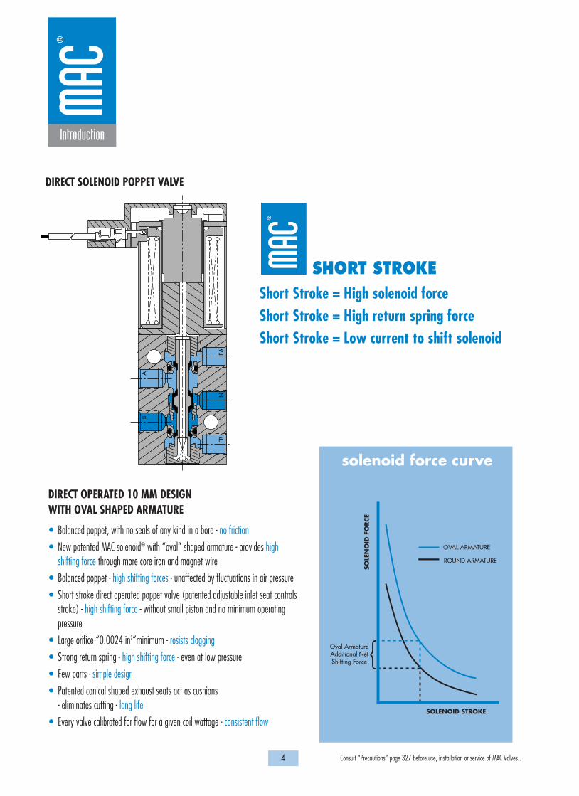
• Balanced poppet, with no seals of any kind in a bore - no friction
• New patented MAC solenoid® with “oval” shaped armature - provides highshifting force through more core iron and magnet wire
• Balanced poppet - high shifting forces - unaffected by fluctuations in air pressure
• Short stroke direct operated poppet valve (patented adjustable inlet seat controlsstroke) - high shifting force - without small piston and no minimum operatingpressure
• Large orifice “0.0024 in2”minimum - resists clogging
• Strong return spring - high shifting force - even at low pressure
• Few parts - simple design
• Patented conical shaped exhaust seats act as cushions- eliminates cutting - long life
• Every valve calibrated for flow for a given coil wattage - consistent flow
DIRECT OPERATED 10 MM DESIGNWITH OVAL SHAPED ARMATURE
DIRECT SOLENOID POPPET VALVE
Short Stroke = High solenoid force Short Stroke = High return spring forceShort Stroke = Low current to shift solenoid
SHORT STROKE
SOLE
NO
ID F
ORCE
SOLENOID STROKE
Oval ArmatureAdditional NetShifting Force
OVAL ARMATURE
ROUND ARMATURE
{
solenoid force curve

5 Consult “Precautions” page 327 before use, installation or service of MAC Valves..
Introduction
II. MAC’s 4-WAY PILOT SYSTEM – Maximized Shifting ForcesThe balanced 4-way pilot valve provides maximum shifting forces in both directions by supplying air alternately to each end section ofthe spool, similar to double acting rodless cylinder. This system provides maximized shifting forces, equal forces at energization andde- energization, with no resistance to shifting at either end. The result is increased shifting reliability and faster, more consistentresponse times.
P
New concept : 4-way pilot
Small direct 4-way solenoid operated valve
Solenoid pilot operated large valve
EXHAEXH B IN Valves that don’t stick
SHIFTING FORCES unaffected bychanging air pressure (IN/EXH)
- BALANCE -
SHIFTING FORCES virtually unaffectedby typically contaminated air
- WIPING ACTION -
Low friction minimizes resistanceto SHIFTING FORCES
- MINIMAL FRICTION -
HIGH SHIFTING FORCE(Energize)
HIGH SHIFTING FORCE(De-energize)
SOLENOIDVALVESPRING
ENERGIZED4-WAY PILOTVALVEDE-ENERGIZED
4-WAY PILOT

6 Consult “Precautions” page 327 before use, installation or service of MAC Valves..
Introduction
MAC DISTRIBUTORS NETWORK
KEEPING YOUR MACHINES RUNNING AROUND THE CLOCK AROUND THE WORLD
45 countries
200 service centers
1000 factory certified application specialists
3500 employees
$ 50 million inventory
• 30 years experience• Local support• Globally linked network• Special solutions• Global customer partnership
ACT LOCAL
7 Consult “Precautions” page 327 before use, installation or service of MAC Valves..
Introduction
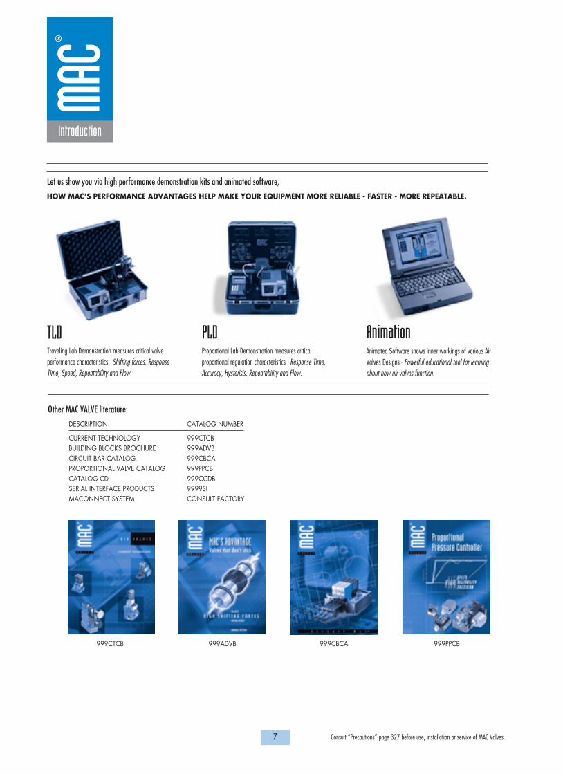
Let us show you via high performance demonstration kits and animated software,
HOW MAC’S PERFORMANCE ADVANTAGES HELP MAKE YOUR EQUIPMENT MORE RELIABLE - FASTER - MORE REPEATABLE.
Other MAC VALVE literature:
DESCRIPTION CATALOG NUMBER
CURRENT TECHNOLOGY 999CTCBBUILDING BLOCKS BROCHURE 999ADVBCIRCUIT BAR CATALOG 999CBCAPROPORTIONAL VALVE CATALOG 999PPCBCATALOG CD 999CCDBSERIAL INTERFACE PRODUCTS 9999SIMACONNECT SYSTEM CONSULT FACTORY
999CTCB 999ADVB 999CBCA 999PPCB
TLDTraveling Lab Demonstration measures critical valveperformance characteristics - Shifting forces, ResponseTime, Speed, Repeatability and Flow.
AnimationAnimated Software shows inner workings of various AirValves Designs - Powerful educational tool for learningabout how air valves function.
PLDProportional Lab Demonstration measures criticalproportional regulation characteristics - Response Time,Accuracy, Hysterisis, Repeatability and Flow.
8 Consult “Precautions” page 327 before use, installation or service of MAC Valves..
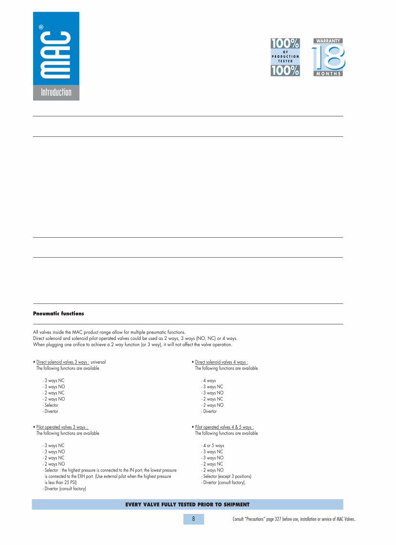
MAC Valves 18 month guarantee plus lifetime coil guarantee
The MAC Valves organization has established a reputation over many years for fulfilling the needs and requirements of the users of its products. All MAC Valves are quality products specifically designed and built for long and rugged service. Therefore, all valves appearing in this catalog are guaranteedfor a period of eighteen months from the original date of shipment from our factory. In addition to this eighteen month Guarantee, MAC Valves, Inc. guaranteesthe electrical coils on every one of the valves listed in this catalog for life. LIMITATION OF GUARANTEE: This Guarantee is limited to the replacement orrebuilding of any valve which should fail to operate properly. Valves, under the MAC Guarantee, must be returned (with or without bases) transportation prepaidand received at our factory within the Garantee period. They will be returned to the customer at the expense of MAC Valves, Inc., and will carry the sameguarantee as provided under the Flat Rate Rebuild Program. DISCLAIMER OF GUARANTEE: No claims for labor, material, time, damage or transportation areallowable nor will any valve be replaced or rebuilt under this guarantee which has been damaged by the purchaser not in the normal course of its use andmaintenance during the warranty period. The guarantee does not apply to loss or damage caused by fire, theft, riot, explosion, labor dispute, act of God, orother causes beyond the control of MAC Valves, Inc. MAC Valves, Inc. shall in no event be liable for remote, special or consequential damages under the MACGuarantee, nor under any implied warranties, including the implied warranty of merchantability.The above Guarantee is our manner of extending the engineering and service resources of the MAC Valves, Inc. organization to assure our customer long, andcontinued satisfaction.
The flat rate rebuild program
Valves no longer covered by the MAC Guarantee can be rebuilt under the Flat Rate Rebuild program. Our constant research and testing program is dedicated toextending the life of our valves and making them even more reliable under the most adverse operating conditions. Valves returned under this program arecompletely disassembled , inspected, rebuilt to current operating standards wherever possible, tested and returned within a few weeks for a nominal flat ratecharge. All rebuilt valves carry for 90 days from date of shipment from our factory the same guarantee as provided for new valves.
Pneumatic functions
All valves inside the MAC product range allow for multiple pneumatic functions.Direct solenoid and solenoid pilot operated valves could be used as 2 ways, 3 ways (NO, NC) or 4 ways.When plugging one orifice to achieve a 2 way function (or 3 way), it will not affect the valve operation.
Introduction
1818100%100%
100%100% M O N T H S
WARRANTY
O FP R O D U C T I O N
T E S T E D
• Direct solenoid valves 3 ways : universalThe following functions are available
- 3 ways NC- 3 ways NO- 2 ways NC- 2 ways NO- Selector- Divertor
• Direct solenoid valves 4 ways :The following functions are available
- 4 ways - 3 ways NC- 3 ways NO- 2 ways NC- 2 ways NO- Divertor
• Pilot operated valves 3 ways : The following functions are available
- 3 ways NC- 3 ways NO- 2 ways NC- 2 ways NO- Selector : the highest pressure is connected to the IN port; the lowest pressure is connected to the EXH port. (Use external pilot when the highest pressure is less than 25 PSI)
- Divertor (consult factory)
• Pilot operated valves 4 & 5 ways :The following functions are available
- 4 or 5 ways - 3 ways NC- 3 ways NO- 2 ways NC- 2 ways NO- Selector (except 3 positions)- Divertor (consult factory).
EVERY VALVE FULLY TESTED PRIOR TO SHIPMENT
9 Consult “Precautions” page 327 before use, installation or service of MAC Valves..
S e c t i o n 1 Direct solenoid and solenoid pilot operated valves

P. 15P. 19P. 23
P. 33P. 35 P. 41 P. 43
P. 47 P. 49P. 53 P. 55 P. 59 P. 61
P. 65P. 69P. 73P. 77P. 81
P. 95 P. 97P. 103 P. 105
P. 111 P. 113P. 121
P. 125 P. 127P. 133 P. 135
P. 141 P. 143P. 147 P. 149
P. 159P. 161 P. 163
P. 173P. 177
P. 181 P. 165P. 187 P. 189P. 193 P. 195
10 Consult “Precautions” page 327 before use, installation or service of MAC Valves..
Function Port size Flow (Max) Cv Individual mounting
D i r e c t s o l e n o i d a n d
3/23/2 - 2/23/23/23/23/23/23/23/23/2 - 2/23/2 - 2/23/2 - 2/25/24/24/25/2 - 5/35/25/25/25/2 - 5/35/25/2 - 5/35/2 - 5/35/2 - 5/35/2 - 5/35/2 - 5/35/2 - 5/35/2 - 5/35/2 - 5/35/2 - 5/35/2 - 5/3
0.0820.120.30.30.30.40.40.5 1.21.520.060.00.10.3 0.3 0.4 0.4 0.51.01.1 1.1 1.01.21.2 3.8 3.41.00.431.83.06.1
Inline Sub-base non “plug-in”
Sub-base “plug-in”
Sub-base/manifold basenon “plug-in” with latching
solenoid
Sub-base/manifold base
“plug-in” with latching
solenoid
Valve only – No base
non “plug-in”Conform to ISO 5599/1
Valve only – No base “plug-in”
Conform to ISO 5599/2
Valve only – No base
non “plug-in”Conform to
ISO 15407/1
M3M5 - #10-321/8”1/8” - #10-321/8” - 5/321/8”#10-32 - 1/4” O.D. tube receptacle
1/8” - 1/4”1/8” - 1/4” O.D. tube receptacle
1/8” - 1/4”3/4” - 1”1 1/2” - 2” - 2 1/2”M5 - #10-321/8” - #10-321/8” - 5/32 #10-32 - 1/4” O.D. tube receptacle
#10-32 - 1/4” O.D. tube receptacle
1/8” - 1/4”1/8”1/8”1/8”1/8” - 1/4”1/8” - 1/4” - 3/8”1/4” - 3/8”3/8” - 1/2”1/4” - 3/8” - 1/2”1/4”1/8”1/4” - 3/8”3/8” - 1/2”1/2” - 3/4”
O.D. pressed-intube receptacle
O.D. pressed-intube receptacle

11 Consult “Precautions” page 327 before use, installation or service of MAC Valves..
Manifold mounting Series
s o l e n o i d p i l o t o p e r a t e d v a l v e s
P. 25P. 27 P. 29
P. 37 P. 39 P. 41 P. 43
P. 57 P. 55 P. 59 P. 61
P. 83P. 85 P. 87 P. 89 P. 91
P. 99 P. 101P. 103 P. 105
P. 115 P. 117
P. 129 P. 131P. 133 P. 135
P. 151 P. 153 P. 165 P. 167
P.173P.177
P. 181 P. 183P. 187 P. 189P. 193 P. 195
stacking Manifold basenon “plug-in”
Manifold base“plug-in”
Manifold base“plug-in” with
pressureregulators
Manifold base“plug-in” withflow controls
Manifold base“plug-in”
with PR & FC
Sub-base/manifold basenon “plug-in” with latching
solenoid
Sub-base/manifold base
“plug-in” with latching
solenoid
Valve only – No base
non “plug-in”Conform to ISO 5599/1
Valve only – No base “plug-in”
Conform to ISO 5599/2
Valve only – No base
non “plug-in”Conform to
ISO 15407/1
36
32
3738
3334
5267
46
44
47
42
400
48
92
93
ISO 1ISO 2 ISO 3
69
48P
ISO 01ISO 02
13 Consult “Precautions” page 327 before use, installation or service of MAC Valves..
Individual mounting Series
D i r e c t s o l e n o i d a n d s o l e n o i d p i l o t o p e r a t e d v a l v e s
SERIES FEATURES
36
32
3738
3334
5267
46
44
47
42
400
48
92
93
ISO 1ISO 2 ISO 3
69
48P
ISO 01ISO 02
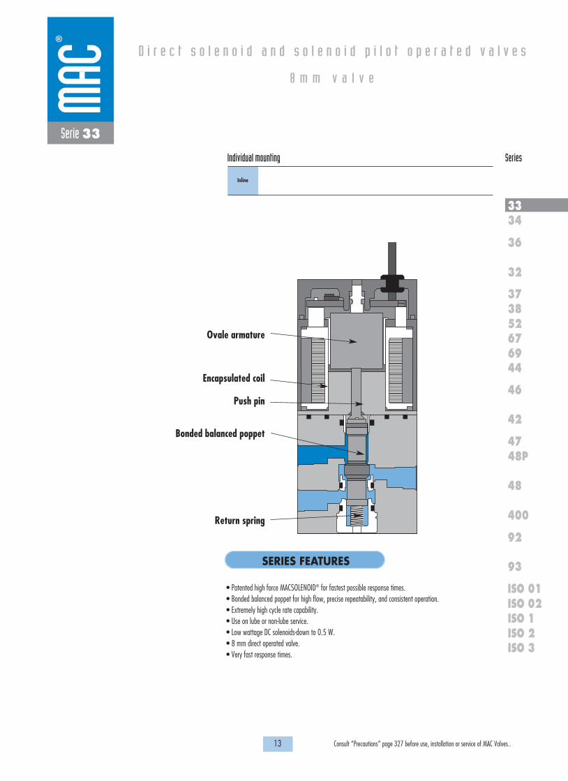
Serie 33
Inline
• Patented high force MACSOLENOID® for fastest possible response times.• Bonded balanced poppet for high flow, precise repeatability, and consistent operation.• Extremely high cycle rate capability.• Use on lube or non-lube service.• Low wattage DC solenoids-down to 0.5 W.• 8 mm direct operated valve.• Very fast response times.
Bonded balanced poppet
Ovale armature
Encapsulated coil
Push pin
Return spring
8 m m v a l v e

Function Port size Flow (Max) Individual mounting Series
OPERATIONAL BENEFITS
D i r e c t s o l e n o i d a n d s o l e n o i d p i l o t o p e r a t e d v a l v e s
H O W T O O R D E R
15 Consult “Precautions” page 327 before use, installation or service of MAC Valves..
36
32
3738
3334
5267
46
44
47
42
400
48
92
93
ISO 1ISO 2 ISO 3
69
48P
ISO 01ISO 02
Series 33
8 m m v a l v e
1. 8mm valve direct solenoid operated.2. Balanced poppet, immune to pressure variations.3. Short stroke with high flow.4. Patented solenoid develops high shifting forces.5. Low wattage solenoids.6. Powerful return spring.7. Extremely fast response times.
Port size
M3
N.C. Only
33A-AAB-RXXX-XXX
N.C. Only **
33A-BAB-RXXX-XXX
** For use with solenoids above 4.0 W - MOD number required. (Consult factory)
R XXX-XXXSOLENOID OPERATOR �
Voltage
DA 24 VDC (0.5W)DB 24 VDC (1.0W)DC 24 VDC (1.8W)DF 24 VDC (4.0W)DG 12 VDC (0.5W)DH 12 VDC (1.0W)DJ 12 VDC (1.8W)DM 12 VDC (4.0W)
Lead wire length
0 No Lead wire*A 18”B 24”C 36”D 48”E 72”
Manual operator
0 No manual operator1 Non-locking recessed3 Non-locking extended
Electrical connection
BA Flying leadsBB Flying leads w/LEDBC Flying leads w/MOVBD Flying leads w/LED & MOV
RA Mini JAC Solenoid plug-inRB Mini JAC Solenoid plug-in
w/LEDRC Mini JAC Solenoid plug-in
w/MOVRD Mini JAC Solenoid plug-in
w/LED & MOV
TA JST Solenoid plug-inTB JST Solenoid plug-in w/LEDTC JST Solenoid plug-in w/MOVTD JST Solenoid plug-in w/LED &
MOV
XX X X XX
* Not available for flyingleads connectors
3/2 NC M3 0.082 Cv Inline
* Other options available, see page 321.
Washdown capability is possible for the “B” and “R” type electrical connectors.Consult factory for ordering information.
Patents and patents pending

35,3
10,6
4,5
20,2
4,6
16,0
13,51,30
3,4
8,20
8,004,00
7,5
Ø 2,2Thru Typ (2)
4,0
1818100%100%
100%100% M O N T H S
WARRANTY
O FP R O D U C T I O N
T E S T E D
D I M E N S I O N S
T E C H N I C A L D A T A
Dimensions shown are metric (mm)
16 Consult “Precautions” page 327 before use, installation or service of MAC Valves..
Fluid :
Pressure range :
Lubrication :
Filtration :
Temperature range :
Flow :
Coil :
Voltage range :
Power :
Compressed air, vacuum, inert gases
Vacuum to 120 PSI
Not required, if used select a medium aniline point lubricant (between 180°F and 210°F)
40µ
0°F to 120°F (-18°C to +50°C)
4W: (Cv .082) - 3W: (Cv .062) - 2.5W: (Cv .062) - 1.8W: (Cv .055) - 1.0W: (Cv .030) - 0.5W: (Cv .020)
Class A wire (#26 AWG x18), continuous duty
-15% to +10% of nominal voltage
4.0W - 3.0W - 2.5W - 1.8W - 1.0W - 0.5W
Series 33
Shown with JST Connector

17
Individual mounting Series
D i r e c t s o l e n o i d a n d s o l e n o i d p i l o t o p e r a t e d v a l v e s
SERIES FEATURES
36
32
3738
3334
5267
46
44
47
42
400
48
92
93
ISO 1ISO 2 ISO 3
69
48P
ISO 01ISO 02
Consult “Precautions” page 327 before use, installation or service of MAC Valves..
Individual mounting Series
Inline
Series 34
D i r e c t s o l e n o i d a n d s o l e n o i d p i l o t o p e r a t e d v a l v e s
• High force MACSOLENOID®.• Universal porting.• # 10-32 or M5 ports.• Rated for lubricated or non-lubricated service.• 10 mm direct operated.
Push pin
Manual operator
Armature
Coil
Poppet
“D” seal
Valve spring

Function Port size Flow (Max) Individual mounting Series
OPERATIONAL BENEFITS
D i r e c t s o l e n o i d a n d s o l e n o i d p i l o t o p e r a t e d v a l v e s
H O W T O O R D E R
19 Consult “Precautions” page 327 before use, installation or service of MAC Valves..
36
32
3738
3334
5267
46
44
47
42
400
48
92
93
ISO 1ISO 2 ISO 3
69
48P
ISO 01ISO 02
Inline
Series 34
3/2 NO-NC, 2/2 NO-NC M5, # 10-32 0.12 Cv
1. 10 mm valve, direct solenoid operated. 2. Balanced poppet, immune to variations of
pressure.3. Short stroke with high flow.4. Patented solenoid develops high shifting
forces.5. Powerful return spring.6. Manual operator standard on all valves.
Port size
M5
# 10-32
Universal valve
34C-ABA-G XXX-XXX
34C-AAA-G XXX-XXX
NC only valve
34C-ABB-G XXX-XXX
34C-AAB-G XXX-XXX
2
1 3
2
1 3
G XXX-XXX *SOLENOID OPERATOR �
Voltage
AA 120 VAC (2.5W)DC 24 VDC (1.8W)DD 24 VDC (2.5W)DF 24 VDC (4.0W)
Wire length
A 18”B 24”C 36”
Manual operator
1 Non-locking recessed3 Non-locking extended
Electrical connection
BA Flying leadsBT Flying leads with lightGA MAC JAC Solenoid plug-inGB MAC JAC Solenoid plug-in
w/DiodeGC MAC JAC Solenoid plug-in
w/MOVGD MAC JAC Solenoid plug-in
w/LEDGE MAC JAC Solenoid plug-in
w/Diode & LEDGF MAC JAC Solenoid plug-in
w/MOV & LEDGG MAC JAC Solenoid plug-in
w/RectifierGH MAC JAC Solenoid plug-in
w/Rectifier & LEDKA Plug-in wire assemblyKC Plug-in wire assembly with
rectifier and lightKT Plug-in wire assembly with
light
XX X X XX
Note : AC voltage requires connector with rectifier.* Other options available, see page 311.
Washdown capability is possible for the “G” type electrical connectors.Consult factory for ordering information.

14,25
4,25
0,8
20,0 12,0
5,3
7,0
10,0
20,0
4,0
31,5
2
1
3
50,2
9,3
5,0
10,0
CL CL CL
1818100%100%
100%100% M O N T H S
WARRANTY
O FP R O D U C T I O N
T E S T E D
D I M E N S I O N S
T E C H N I C A L D A T A
Dimensions shown are metric (mm)
20 Consult “Precautions” page 327 before use, installation or service of MAC Valves..
3,3 DIA. MTG.HOLES TYP. (2)
Series 34
Fluid :
Pressure range :
Lubrication :
Filtration :
Temperature range :
Flow :
Coil :
Voltage range :
Power :
Response times :
(with 4 W coil)
Compressed air, vacuum, inert gases
Vacuum to 120 PSI
Not required, if used select a medium aniline point lubricant (between 180°F and 210°F)
40 µ
0°F to 120°F (-18°C to +50°C)
4 W : (0.12 Cv) – 2.5 W : (0.10 Cv) – 1.8 W : (0.06 Cv)
Class A wire (#22 AWG x 18), continuous duty
-15% to +10% of nominal voltage
4 W – 2.5 W – 1.8 W
Energize : 3.4 ms
De-energize : 1.5 ms

21 Consult “Precautions” page 327 before use, installation or service of MAC Valves..
Individual mounting Series
D i r e c t s o l e n o i d a n d s o l e n o i d p i l o t o p e r a t e d v a l v e s
SERIES FEATURES
36
32
3738
3334
5267
46
44
47
42
400
48
92
93
ISO 1ISO 2 ISO 3
69
48P
ISO 01ISO 02
Inline
Manifold base“plug-in”
Manifold base“plug-in” with
pressureregulators
Stacking
Series 36
Manifold mounting
• Patented high force MACSOLENOID® for fastest possible response times.• Bonded balanced poppet for high flow, precise repeatability, and consistent operation.• Balanced poppet permits versatility in function — may be used as 3-way or 2-way normally open or
normally closed and may be used for vacuum, divertor, or selector applications.• Extremely high cycle rate capability.• Use on lube or non-lube service.• Manual overrides as standard.• Various solenoid enclosures and plug-in connectors.• Optional surge suppression available.• Low wattage DC solenoids — down to 1.8 watts.• Rectified AC voltage.
2
1
3
Push pin
Oval shaped armature
Encapsulated coil
Bonded balanced poppet
Return spring

Function Port size Flow (Max) Individual mounting Series
OPERATIONAL BENEFITS
D i r e c t s o l e n o i d a n d s o l e n o i d p i l o t o p e r a t e d v a l v e s
H O W T O O R D E R
23 Consult “Precautions” page 327 before use, installation or service of MAC Valves..
36
32
3738
3334
5267
46
44
47
42
400
48
92
93
ISO 1ISO 2 ISO 3
69
48P
ISO 01ISO 02
Series 36
3/2 1/8” 0.3 Cv Inline
1. Balanced poppet, immune to variations ofpressure.
2. Patented solenoid develops high shiftingforces.
3. Short stroke with high flow.4. Higher forces result in lower wattages for
given flow.5. Powerful return spring.
Port size
1/8” NPTF
Universal valve
36A-AAA-J XXX-XXX
NC only valve
36A-AAB-J XXX-XXX
2
1 3
2
1 3
J XXX-XXX * (-G) Add "G" for groundSOLENOID OPERATOR �
Voltage
AA 120 VAC (5.4W)DA 24 VDC (5.4W)DB 12 VDC (5.4W)DC 24 VDC (2.4W)DD 12 VDC (2.4W)
Lead wire length
A 18”B 24”C 36”
Manual operator
1 Non-locking recessed2 Locking recessed
Electrical connection
BA Flying leadsGA MAC JAC solenoid plug-in GB MAC JAC solenoid plug-in
with diodeGD MAC JAC solenoid plug-in
with lightGG MAC JAC solenoid plug-in
with rectifier
XX X X XX
* Other options available, see page 317.Note : - AC voltage requires connector with rectifier.
- With the MAC JAC, washdown capability is possible. Consultfactory for washdown modification number.

21.5
30.5
42.3
23.3
58.2
13.1
8.2
4.5
15.3
3.38.0
Ø 3.4
16.6
10.1
1818100%100%
100%100% M O N T H S
WARRANTY
O FP R O D U C T I O N
T E S T E D
D I M E N S I O N S
T E C H N I C A L D A T A
Dimensions shown are metric (mm)
24 Consult “Precautions” page 327 before use, installation or service of MAC Valves..
Series 36
Fluid :
Pressure range :
Lubrication :
Filtration :
Temperature range :
Flow :
Coil :
Voltage range :
Protection :
Power :
Compressed air, vacuum, inert gases
Vacuum to 120 PSI
Not required, if used select a medium aniline point lubricant (between 180°F and 210°F)
40 µ
0°F to 120°F (-18°C to +50°C)
1.8 Watt: (0.15 Cv), 2.4 Watt: (0.15 Cv), 5.4 Watt: (0.30 Cv)
Class A wire (#22 AWG x 12), continuous duty
-15% to +10% of nominal voltage
Consult factory
5.4 W – 2.4 W – 1.8 W
• BSPP threadsOption :

Function Port size Flow (Max) Individual mounting Series
OPERATIONAL BENEFITS
D i r e c t s o l e n o i d a n d s o l e n o i d p i l o t o p e r a t e d v a l v e s
H O W T O O R D E R
25 Consult “Precautions” page 327 before use, installation or service of MAC Valves..
36
32
3738
3334
5267
46
44
47
42
400
48
92
93
ISO 1ISO 2 ISO 3
69
48P
ISO 01ISO 02
Series 36
3/2 1/8" – # 10-32 0.3 Cv Stacking
1. Balanced poppet, immune to variations ofpressure.
2. Patented solenoid develops high shiftingforces.
3. Short stroke with high flow.4. Higher forces result in lower wattages for
given flow.5. Powerful return spring.
Port size
1/8” NPTF
# 10-32
NC only stacking
36A-SAB-J XXX-XXX
36A-SBB-J XXX-XXX
NC stackingUniversal poppet
36A-SAC-J XXX-XXX
36A-SBC-J XXX-XXX
NO stackingUniversal poppet
36A-SAD-J XXX-XXX
36A-SBD-J XXX-XXX
CYL
IN EXH
CYL
INEXH
CYL
INEXH
J XXX-XXX * (-G) Add "G" for groundSOLENOID OPERATOR �
Voltage
AA 120 VAC (5.4W)DA 24 VDC (5.4W)DB 12 VDC (5.4W)DC 24 VDC (2.4W)DD 12 VDC (2.4W)
Lead wire length
A 18”B 24”C 36”
Manual operator
1 Non-locking recessed2 Locking recessed
Electrical connection
BA Flying leadsGA MAC JAC solenoid plug-in GB MAC JAC solenoid plug-in
with diodeGD MAC JAC solenoid plug-in
with lightGG MAC JAC solenoid plug-in
with rectifier
XX X X XX
* Other options available, see page 317. Note : - AC voltage requires connector with rectifier.
- With the MAC JAC, washdown capability is possible. Consultfactory for washdown modification number.
End plate kit required (port size 1/4") : M-36001-01.
36A-SAB-JXXX-XXX
B O D Y T Y P E O P T I O N S
S Stacking bodyT Stacking body with bottom inlet

1/4" COMMONS
TYP. TYP.
86.0
15.0 16.5 15.08.3
5.0
22.2
59.2
51.3
14.1
9.0
35.2
9.3
4.7
1818100%100%
100%100% M O N T H S
WARRANTY
O FP R O D U C T I O N
T E S T E D
D I M E N S I O N S
T E C H N I C A L D A T A
Dimensions shown are metric (mm)
26 Consult “Precautions” page 327 before use, installation or service of MAC Valves..
Series 36
Fluid :
Pressure range :
Lubrication :
Filtration :
Temperature range :
Flow :
Coil :
Voltage range :
Protection :
Power :
Compressed air, vacuum, inert gases
Vacuum to 120 PSI
Not required, if used select a medium aniline point lubricant (between 180°F and 210°F)
40 µ
0°F to 120°F (-18°C to +50°C)
1.8 Watt: (0.15 Cv), 2.4 Watt: (0.15 Cv), 5.4 Watt: (0.30 Cv)
Class A wire (#22 AWG x 12), continuous duty
-15% to +10% of nominal voltage
Consult factory
5.4 W – 2.4 W – 1.8 W
• BSPP threads
• Inlet & exhaust isolator plate : N-36001 • Inlet isolator : N-36002 • Exhaust isolator : N-36003 • Tie rod (x2) : 79411
Option :
Spare parts :
Note: Isolator adds 2.5 mmto length of stack.

Function Port size Flow (Max) Individual mounting Series
OPERATIONAL BENEFITS
D i r e c t s o l e n o i d a n d s o l e n o i d p i l o t o p e r a t e d v a l v e s
H O W T O O R D E R
27 Consult “Precautions” page 327 before use, installation or service of MAC Valves..
36
32
3738
3334
5267
46
44
47
42
400
48
92
93
ISO 1ISO 2 ISO 3
69
48P
ISO 01ISO 02
Series 36
3/2 1/8" - 5/32 Pressed-in 0.3 Cvtube receptacle
Manifold base“plug-in”
1. Balanced poppet, immune to variations ofpressure.
2. Patented solenoid develops high shiftingforces.
3. Short stroke with high flow.4. Higher forces result in lower wattages for
given flow.5. Powerful return spring.
Port size
Valve less base
1/8” NPTF
5/32 tube receptacle
Universal ValveNormally Closed
36A-J00-00-J XXP-XXX
36A-JSA-AE-J XXP-XXX
36A-JSF-AE-J XXP-XXX
Universal ValveNormally Open
36A-K00-00-J XXP-XXX
36A-KSA-AF-J XXP-XXX
36A-KSF-AF-J XXP-XXX
Normally Closed Only
36A-L00-00-J XXP-XXX
36A-LSA-AE-J XXP-XXX
36A-LSF-AE-J XXP-XXX
2
1 3
2
1 3
2
1 3
Voltage
AA 120 VAC (5.4W)DA 24 VDC (5.4W)DB 12 VDC (5.4W)DC 24 VDC (2.4W)DD 12 VDC (2.4W)
Manual operator
1 Non-locking recessed2 Locking recessed
Electrical connection
FA Base plug-inFB Base plug-in with diodeFG Base plug-in with rectifier
J XX P-XXX * (-G) Add “G” for groundSOLENOID OPERATOR �
XX X XX
* Other options available, see page 317. Note : AC voltage requires connector with rectifier.
Example : Manifold base only : 36A-0SA-AE (Normally closed manifold base).
End plate kit required (port size 1/4") : M-46003-01.

18.6 16.5 8.0
8.0
24.0
78.0
4.4
94.3
4.0
52.5
19.0
34.2
79.0
95.5
9.522.5
32.8Ø 4.3
TYP. TYP.
TYP.
3/4"-14 NPSM
1/4" COMMONS
1818100%100%
100%100% M O N T H S
WARRANTY
O FP R O D U C T I O N
T E S T E D
D I M E N S I O N S
T E C H N I C A L D A T A
Dimensions shown are metric (mm)
28 Consult “Precautions” page 327 before use, installation or service of MAC Valves..
Series 36
Fluid :
Pressure range :
Lubrication :
Filtration :
Temperature range :
Flow :
Coil :
Voltage range :
Protection :
Power :
Compressed air, vacuum, inert gases
Vacuum to 120 PSI
Not required, if used select a medium aniline point lubricant (between 180°F and 210°F)
40 µ
0°F to 120°F (-18°C to +50°C)
1.8W : (0.20 Cv) – 2.4W : (0.20 Cv) – 5.4W : (0.30 Cv)
Class A continuous duty, #22 AWG x 12 base leads
-15% to +10% of nominal voltage
Consult Factory
5.4 W – 2.4 W – 1.8 W
• BSPP threads
• Inlet isolator : 28501 • Exhaust isolator : 28502 • Valve cover plate : M-46002 • Tie rod (x2) : 79443
Option :
Spare parts :
Note: For Normally closed manifold the “A” port is plugged.For Normally open manifold the “B” port is plugged.

Function Port size Flow (Max) Individual mounting Series
OPERATIONAL BENEFITS
D i r e c t s o l e n o i d a n d s o l e n o i d p i l o t o p e r a t e d v a l v e s
H O W T O O R D E R
29 Consult “Precautions” page 327 before use, installation or service of MAC Valves..
36
32
3738
3334
5267
46
44
47
42
400
48
92
93
ISO 1ISO 2 ISO 3
69
48P
ISO 01ISO 02
Series 36
3/2 1/8" - 5/32 Pressed-in 0.3 Cvtube receptacle
Manifold base“plug-in” with
pressureregulators
1. Balanced poppet, immune to variations ofpressure.
2. Patented solenoid develops high shiftingforces.
3. Short stroke with high flow.4. Higher forces result in lower wattages for
given flow.5. Powerful return spring.
Port size
Valve less base
1/8” NPTF
5/32 tube receptacle
Universal ValveNormally Closed
36A-J00-00-J XXP-XXX
36A-JSA-AG-J XXP-XXX
36A-JSF-AG-J XXP-XXX
Universal ValveNormally Open
36A-K00-00-J XXP-XXX
36A-KSA-AH-J XXP-XXX
36A-KSF-AH-J XXP-XXX
Normally Closed Only
36A-L00-00-J XXP-XXX
36A-LSA-AG-J XXP-XXX
36A-LSF-AG-J XXP-XXX
2
1 3
2
1 3
2
1 3
Voltage
AA 120 VAC (5.4W)DA 24 VDC (5.4W)DB 12 VDC (5.4W)DC 24 VDC (2.4W)DD 12 VDC (2.4W)
Manual operator
1 Non-locking recessed2 Locking recessed
Electrical connection
FA Base plug-inFB Base plug-in with diodeFG Base plug-in with rectifier
J XX P-XXX * (-G) Add “G” for groundSOLENOID OPERATOR �
XX X XX
* Other options available, see page 317.Note : AC voltage requires connector with rectifier.
Note : All manifold bases are only available with a bottom cylinder port.
Example : Manifold base only : 36A-0SA-AJ (Normally closed manifold base & regulator with knob).
End plate kit required (port size 1/4") : M-46003-01.
36A-JSA-AG-JXX P-XXX
O P T I O N S
G NC manifold & regulator with slotted stem adjustmentS NC manifold & regulator with locking slotted stem adjustmentJ NC manifold & regulator with knob adjustment
36A-KSA-AH-JXX P-XXX
H NO manifold & regulator with slotted stem adjustmentT NO manifold & regulator with locking slotted stem adjustmentK NO manifold & regulator with knob adjustment

52.5
4.0
Ø 4.3
94.34.4
69.2
95.5
79.0
19.0
34.2
9.5
22.5
32.8
7.9
47.6
32.6
16.518.6
78.0
1/4" COMMONS
3/4"-14 NPSM
PORT1/8" GAGE
TYP.
TYP.
TYP.
1818100%100%
100%100% M O N T H S
WARRANTY
O FP R O D U C T I O N
T E S T E D
D I M E N S I O N S
T E C H N I C A L D A T A
Dimensions shown are metric (mm)
30 Consult “Precautions” page 327 before use, installation or service of MAC Valves..
Series 36
Fluid :
Pressure range :
Lubrication :
Filtration :
Temperature range :
Flow :
Coil :
Voltage range :
Protection :
Power :
Compressed air, vacuum, inert gases
Vacuum to 120 PSI
Not required, if used select a medium aniline point lubricant (between 180°F and 210°F)
40 µ
0°F to 120°F (-18°C to +50°C)
1.8W : (0.20 Cv) – 2.4W : (0.20 Cv) – 5.4W : (0.30 Cv)
Class A continuous duty, #22 AWG x 12 base leads
-15% to +10% of nominal voltage
Consult Factory
5.4 W – 2.4 W – 1.8 W
• BSPP threads
• Inlet isolator : 28501 • Exhaust isolator : 28502 • Valve cover plate : M-46002 • Tie rod (x2) : 79443
Option :
Spare parts :
Note: For Normally closed manifold the “A” port is plugged.For Normally open manifold the “B” port is plugged.

31 Consult “Precautions” page 327 before use, installation or service of MAC Valves..
Individual mounting Series
D i r e c t s o l e n o i d a n d s o l e n o i d p i l o t o p e r a t e d v a l v e s
SERIES FEATURES
36
32
3738
3334
5267
46
44
47
42
400
48
92
93
ISO 1ISO 2 ISO 3
69
48P
ISO 01ISO 02
Sub-base non “plug-in”
Sub-base“plug-in”
Sub-base/manifold basenon “plug-in” with latching
solenoid
Sub-base/manifold base
“plug-in” with latching
solenoid
Manifold base“plug-in”
Sub-base/manifold basenon “plug-in” with latching
solenoid
Sub-base/manifold base
“plug-in” with latching
solenoid
Manifold basenon “plug-in”
Series 32
Manifold mounting
• High force MACSOLENOID®.• Integral 4-way pilot design.• Internal or external pilot.• Normally open or normally closed function.• Universal function (external pilot).• Rectified AC voltage.• Latching solenoid technology.
1 2 3
Solenoid
Manual operator
Integral 4-way pilot
Air returnBonded spool

Function Port size Flow (Max) Individual mounting Series
OPERATIONAL BENEFITS
D i r e c t s o l e n o i d a n d s o l e n o i d p i l o t o p e r a t e d v a l v e s
H O W T O O R D E R
33 Consult “Precautions” page 327 before use, installation or service of MAC Valves..
36
32
3738
3334
5267
46
44
47
42
400
48
92
93
ISO 1ISO 2 ISO 3
69
48P
ISO 01ISO 02
Series 32
3/2 NO-NC 1/8” 0.4 CvSub-base
non “plug-in”
1. 3-way valve with 4-way integral pilot.2. 10 mm valve (stacks on 10.5 mm centers).3. High flow (up to 0.4 Cv).4. Fast, repeatable response times.5. Maximum shifting forces in both directions.
32B-XMX-XAX-GXXX-XXX
O P T I O N S
A Individual base – Side portB Individual base – Bottom port
M Pilot exhaust muffledP Pilot exhaust piped (# 10-32)U Pilot exhaust to main exhaust (not available with external pilot)
NO valve
32B-BMA-000-GXXX-XXX
32B-BMB-000-GXXX-XXX
32B-BMA-CAL-GXXX-XXX
32B-BMB-CAM-GXXX-XXX
NC valve
32B-AMA-000-GXXX-XXX
32B-AMB-000-GXXX-XXX
32B-AMA-CAL-GXXX-XXX
32B-AMB-CAM-GXXX-XXX
Universal valve
32B-GMB-000-GXXX-XXX
32B-GMB-CAM-GXXX-XXX
Port size
Valve less base
1/8” NPTF
Pilot air
Internal
External
Internal
External
Note : Above codes are for side port.
G XXX-XXX *STANDARD SOLENOID OPERATOR �
Pilot/Base Configuration :
Voltage
AA 120 VAC (2.5W)DA 24 VDC (1.0W)DC 24 VDC (1.8W)DD 24 VDC (2,5W)DF 24 VDC (4.0W)
Wire length
A 18”B 24”C 36”
Manual operator
1 Non-locking recessed2 Locking recessed
Electrical connection
BA Flying leadsBT Flying leads with lightGA MAC JAC Solenoid plug-inGB MAC JAC Solenoid plug-in
w/DiodeGC MAC JAC Solenoid plug-in
w/MOVGD MAC JAC Solenoid plug-in
w/LEDGE MAC JAC Solenoid plug-in
w/Diode & LEDGF MAC JAC Solenoid plug-in
w/MOV & LEDGG MAC JAC Solenoid plug-in
w/RectifierGH MAC JAC Solenoid plug-in
w/Rectifier & LEDKA Plug-in wire assy.KT Plug-in wire assy. with lightKD Plug-in wire assy. with
rectifier & light & ground
XX X X XX
Note : AC voltage requires connector with rectifier.* Other options available, see page 311.Latching solenoid also available, see page 41.With MAC JAC electrical connector washdown capability is possible.Consult factory for modification number.
2 1210
13
21210
13
21210
13

23.1
79.1
31.8
67.4
49.9
24.7
8.0
Ø 4.3
6.0
6.0
4.5
4.0
62.0
37.2
8.0
13
X
2
1818100%100%
100%100% M O N T H S
WARRANTY
O FP R O D U C T I O N
T E S T E D
D I M E N S I O N S
T E C H N I C A L D A T A
Dimensions shown are metric (mm)
34 Consult “Precautions” page 327 before use, installation or service of MAC Valves..
Series 32
Fluid :
Pressure range :
Pilot pressure :
Lubrication :
Filtration :
Temperature range :
Flow :
Coil :
Voltage range :
Power :
Response times :
(with 4 W coil)
Compressed air, vacuum, inert gases
Internal Pilot : 20 to 120 PSI
External Pilot : Vacuum to 120 PSI
20 to 120 PSI
Not required, if used select a medium aniline point lubricant (between 180°F and 210°F)
40 µ
0°F to 120°F (-18°C to +50°C)
1/8” : (0.40 Cv)
Class A wire (#22 AWG x 18), continuous duty
-15% to +10% of nominal voltage
1.0 to 4.0 W
Energize : 5 ms
De-energize : 5 ms
• BSPP threadsOptions :

Function Port size Flow (Max) Individual mounting Series
OPERATIONAL BENEFITS
D i r e c t s o l e n o i d a n d s o l e n o i d p i l o t o p e r a t e d v a l v e s
H O W T O O R D E R
35 Consult “Precautions” page 327 before use, installation or service of MAC Valves..
36
32
3738
3334
5267
46
44
47
42
400
48
92
93
ISO 1ISO 2 ISO 3
69
48P
ISO 01ISO 02
Series 32
3/2 NO-NC # 10-32 - 0.4 Cv1/4” O.D. tube receptacle
Sub-base“plug-in”
1. 3-way valve with 4-way integral pilot.2. 10 mm valve (stacks on 10.5 mm centers).3. High flow (up to 0.4 Cv).4. Fast, repeatable response times.5. Maximum shifting forces in both directions.
32B-XMX-XAX-GXX P-XXX
O P T I O N S
A Individual base – Side portB Individual base – Bottom port
M Pilot exhaust muffledP Pilot exhaust piped (# 10-32)U Pilot exhaust to main exhaust (not available with external pilot)
NO valve
32B-BMA-000-GXXP-XXX
32B-BMB-000-GXXP-XXX
32B-BMA-AAA-GXXP-XXX
32B-BMB-AAB-GXXP-XXX
32B-BMA-EAA-GXXP-XXX
32B-BMB-EAB-GXXP-XXX
NC valve
32B-AMA-000-GXXP-XXX
32B-AMB-000-GXXP-XXX
32B-AMA-AAA-GXXP-XXX
32B-AMB-AAB-GXXP-XXX
32B-AMA-EAA-GXXP-XXX
32B-AMB-EAB-GXXP-XXX
Universal valve
32B-GMB-000-GXXP-XXX
32B-GMB-AAB-GXXP-XXX
32B-GMB-EAB-GXXP-XXX
Port size
Valve less base
# 10-32
1/4” O.D.
Tube receptacle
Pilot air
Internal
External
Internal
External
Internal
External
Note : Above codes are for side port.
Voltage
AA 120 VAC (2.5W)DA 24 VDC (1.0W)DC 24 VDC (1.8W)DD 24 VDC (2.5W)DF 24 VDC (4.0W)
Manual operator
1 Non-locking recessed2 Locking recessed
Electrical connection
SA Base plug-inSJ Base plug-in with lightSS Base plug-in with rectifier & light & ground
G XX P-XXX *STANDARD SOLENOID OPERATOR �
XX X XX
Note : AC voltage requires connector with rectifier.* Other options available, see page 311.Latching solenoid also available, see page 43.Washdown capability is possible, consult factory for modification number.
Pilot/Base Configuration :
2 1210
13
21210
13
21210
13

33.2
5.5
4.8
35.0
114.0
1/4" IN & EXH COMMONS
PILOT1/8" EXTERNAL
1"-11 1/2 CONDUIT
Ø 5.3
94.0
68.4
56.7
23.2
20.022.0
11.19.5
23.7
18.5
2
10
X
31
TYP.
TYP.
#10-32 PORT SHOWN
1818100%100%
100%100% M O N T H S
WARRANTY
O FP R O D U C T I O N
T E S T E D
D I M E N S I O N S
T E C H N I C A L D A T A
Dimensions shown are metric (mm)
36 Consult “Precautions” page 327 before use, installation or service of MAC Valves..
Series 32
Fluid :
Pressure range :
Pilot pressure :
Lubrication :
Filtration :
Temperature range :
Flow :
Coil :
Voltage range :
Power :
Response times :
(with 4 W coil)
Compressed air, vacuum, inert gases
Internal Pilot : 20 to 120 PSI
External Pilot : Vacuum to 120 PSI
20 to 120 PSI
Not required, if used select a medium aniline point lubricant (between 180°F and 210°F)
40 µ
0°F to 120°F (-18°C to +50°C)
# 10-32 : (0.35 Cv) - 1/4 tube receptacle : (0.40 Cv)
Class A continuous duty, #22 AWG x 12 base leads
-15% to +10% of nominal voltage
1.0 to 4.0 W
Energize : 5 ms
De-energize : 5 ms
• M5 port • M7 port • 6 mm O.D. tube receptacleOptions :

Function Port size Flow (Max) Individual mounting Series
OPERATIONAL BENEFITS
D i r e c t s o l e n o i d a n d s o l e n o i d p i l o t o p e r a t e d v a l v e s
H O W T O O R D E R
37 Consult “Precautions” page 327 before use, installation or service of MAC Valves..
36
32
3738
3334
5267
46
44
47
42
400
48
92
93
ISO 1ISO 2 ISO 3
69
48P
ISO 01ISO 02
Series 32
3/2 NO-NC # 10-32 - 0.4 Cv1/4” O.D. tube receptacle
Manifold basenon “plug-in”
1. 3-way valve with 4-way integral pilot.2. 10 mm valve (stacks on 10.5 mm centers).3. High flow (up to 0.4 Cv).4. Fast, repeatable response times.5. Maximum shifting forces in both directions.
32B-XMX-XJX-GXXX-XXX
J Manifold base – Side portK Manifold base – Bottom port
M Pilot exhaust muffledP Pilot exhaust piped (# 10-32)U Pilot exhaust to main exhaust (not available with external pilot)
NO valve
32B-BMA-000-GXXX-XXX
32B-BMB-000-GXXX-XXX
32B-BMA-AJL-GXXX-XXX
32B-BMB-AJM-GXXX-XXX
32B-BMA-EJL-GXXX-XXX
32B-BMB-EJM-GXXX-XXX
NC valve
32B-AMA-000-GXXX-XXX
32B-AMB-000-GXXX-XXX
32B-AMA-AJL-GXXX-XXX
32B-AMB-AJM-GXXX-XXX
32B-AMA-EJL-GXXX-XXX
32B-AMB-EJM-GXXX-XXX
Universal valve
32B-GMB-000-GXXX-XXX
32B-GMB-AJM-GXXX-XXX
32B-FMB-EJM-GXXX-XXX
Port size
Valve less base
# 10-32
1/4” O.D.
Tube receptacle
Pilot air
Internal
External
Internal
External
Internal
External
Note : Above codes are for side port.
Base/Pilot Configuration :
G XXX-XXX *STANDARD SOLENOID OPERATOR �
Voltage
AA 120 VAC (2.5W)DA 24 VDC (1.0W)DC 24 VDC (1.8W)DD 24 VDC (2.5W)DF 24 VDC (4.0W)
Wire length
A 18”B 24”C 36”
Manual operator
1 Non-locking recessed2 Locking recessed
Electrical connection
BA Flying leadsBT Flying leads with lightGA MAC JAC Solenoid plug-inGB MAC JAC Solenoid plug-in
w/DiodeGC MAC JAC Solenoid plug-in
w/MOVGD MAC JAC Solenoid plug-in
w/LEDGE MAC JAC Solenoid plug-in
w/Diode & LEDGF MAC JAC Solenoid plug-in
w/MOV & LEDGG MAC JAC Solenoid plug-in
w/RectifierGH MAC JAC Solenoid plug-in
w/Rectifier & LEDKA Plug-in wire assy.KT Plug-in wire assy. with lightKD Plug-in wire assy. with
rectifier & light & ground
XX X X XX
Note : AC voltage requires connector with rectifier.* Other options available, see page 311.Latching solenoid also available, see page 41.With MAC JAC electrical connector washdown capability is possible.Consult factory for modification number.
Note : Manifold assemblies require an end plate kit : M-32003-01-01 (Internal pilot)M-32003-02-01 (External pilot)
O P T I O N S
32B-000-XXX(i.e. 32B-000-AJL)
Base only :
2 1210
13
21210
13
21210
13

TYP.
M7 PORTS SHOWN
1/4" IN & EXH COMMONS
PILOT1/8" EXTERNAL
TYP.
TYP.
TYP.
19.0
99.9
5.0
4.3
222
X3
1
Ø 5.3
39.6
10.5 18.5
2 222
2
23.3
56.7
70.4
79.1
9.5
11.1
20.4
29.6
24.310.5
5.5
76.5
1818100%100%
100%100% M O N T H S
WARRANTY
O FP R O D U C T I O N
T E S T E D
D I M E N S I O N S
T E C H N I C A L D A T A
Dimensions shown are metric (mm)
38 Consult “Precautions” page 327 before use, installation or service of MAC Valves..
Series 32
Fluid :
Pressure range :
Pilot pressure :
Lubrication :
Filtration :
Temperature range :
Flow :
Coil :
Voltage range :
Power :
Response times :
(with 4 W coil)
Compressed air, vacuum, inert gases
Internal Pilot : 20 to 120 PSI
External Pilot : Vacuum to 120 PSI
20 to 120 PSI
Not required, if used select a medium aniline point lubricant (between 180°F and 210°F)
40 µ
0°F to 120°F (-18°C to +50°C)
# 10-32 : (0.35 Cv) - 1/4 tube receptacle : (0.40 Cv)
Class A wire (#22 AWG x 18), continuous duty
-15% to +10% of nominal voltage
1.0 to 4.0 W
Energize : 5 ms
De-energize : 5 ms
• M5 port • M7 port • 6 mm O.D. tube receptacle• Inlet/Exhaust Isolator : 28454
Options :

Function Port size Flow (Max) Individual mounting Series
OPERATIONAL BENEFITS
D i r e c t s o l e n o i d a n d s o l e n o i d p i l o t o p e r a t e d v a l v e s
H O W T O O R D E R
39 Consult “Precautions” page 327 before use, installation or service of MAC Valves..
36
32
3738
3334
5267
46
44
47
42
400
48
92
93
ISO 1ISO 2 ISO 3
69
48P
ISO 01ISO 02
Series 32
3/2 NO-NC # 10-32 - 0.4 Cv1/4” O.D. tube receptacle
Manifold base“plug-in”
1. 3-way valve with 4-way integral pilot.2. 10 mm valve (stacks on 10.5 mm centers).3. High flow (up to 0.4 Cv).4. Fast, repeatable response times.5. Maximum shifting forces in both directions.
32B-XXX-XJX-GXX P-XXX
O P T I O N S
J Manifold base – Side portK Manifold base – Bottom portL Left end manifold base – Side portM Left end manifold base – Bottom portN Right end manifold base – Side portP Right end manifold base – Bottom port
Note : Manifold assemblies consist of (1) left end manifold, (1) right end manifold and middle station manifolds (options "J" or "K").
NO valve
32B-BMA-000-GXXP-XXX
32B-BMB-000-GXXP-XXX
32B-BMA-AJA-GXXP-XXX
32B-BMB-AJB-GXXP-XXX
32B-BMA-EJA-GXXP-XXX
32B-BMB-EJB-GXXP-XXX
NC valve
32B-AMA-000-GXXP-XXX
32B-AMB-000-GXXP-XXX
32B-AMA-AJA-GXXP-XXX
32B-AMB-AJB-GXXP-XXX
32B-AMA-EJA-GXXP-XXX
32B-AMB-EJB-GXXP-XXX
Universal valve
32B-GMB-000-GXXP-XXX
32B-GMB-AJB-GXXP-XXX
32B-GMB-EJB-GXXP-XXX
Port size
Valve less base
# 10-32
1/4” O.D.
Tube receptacle
Pilot air
Internal
External
Internal
External
Internal
External
Note : Above codes are for side port.
Voltage
AA 120 VAC (2.5W)DA 24 VDC (1.0W)DC 24 VDC (1.8W)DD 24 VDC (2.5W)DF 24 VDC (4.0W)
Manual operator
1 Non-locking recessed2 Locking recessed
Electrical connection
SA Base plug-inSJ Base plug-in with lightSS Base plug-in with rectifier & light & ground
G XX P-XXX *STANDARD SOLENOID OPERATOR �
XX X XX
Note : AC voltage requires connector with rectifier.* Other options available, see page 311.Latching solenoid also available, see page 43.Washdown capability is possible, consult factory for modification number.
Base Configuration :
32B-000-XXX(i.e. 32B-000-AJA)
Base only :
2 1210
13
21210
13
21210
13

1/4" IN & EXH COMMONS
PILOT1/8" EXTERNAL
1"-11 1/2 CONDUIT
Ø 5.3
39.6
10.5 18.5
94.0
68.4
56.7
23.2
20.0
22.0
11.19.5
114.0
5.0
4.3
23.7
66.5
10.5 18.5
2
2
10
2
2
10
X
31
1010
2
22
2
TYP. TYP.
TYP.
TYP.TYP.TYP.
#10-32 PORT SHOWN
1818100%100%
100%100% M O N T H S
WARRANTY
O FP R O D U C T I O N
T E S T E D
D I M E N S I O N S
T E C H N I C A L D A T A
Dimensions shown are metric (mm)
40 Consult “Precautions” page 327 before use, installation or service of MAC Valves..
Series 32
Fluid :
Pressure range :
Pilot pressure :
Lubrication :
Filtration :
Temperature range :
Flow :
Coil :
Voltage range :
Power :
Response times :
(with 4 W coil)
Compressed air, vacuum, inert gases
Internal Pilot : 20 to 120 PSI
External Pilot : Vacuum to 120 PSI
20 to 120 PSI
Not required, if used select a medium aniline point lubricant (between 180°F and 210°F)
40 µ
0°F to 120°F (-18°C to +50°C)
# 10-32 : (0.35 Cv) - 1/4 tube receptacle : (0.40 Cv)
Class A continuous duty, #22 AWG x 12 base leads
-15% to +10% of nominal voltage
1.0 to 4.0 W
Energize : 5 ms
De-energize : 5 ms
• M5 port • M7 port • 6 mm O.D. tube receptacle• Inlet/Exhaust Isolator : 28454
Options :

Function Port size Flow (Max) Individual mounting Series
OPERATIONAL BENEFITS
D i r e c t s o l e n o i d a n d s o l e n o i d p i l o t o p e r a t e d v a l v e s
H O W T O O R D E R
41 Consult “Precautions” page 327 before use, installation or service of MAC Valves..
36
32
3738
3334
5267
46
44
47
42
400
48
92
93
ISO 1ISO 2 ISO 3
69
48P
ISO 01ISO 02
Series 32
3/2 NO-NC # 10-32 - 0.4 Cv1/4” O.D. tube receptacle
Sub-base/manifold basenon “plug-in” with latching
solenoid
1. 3-way valve with 4-way integral pilot.2. 10 mm valve (stacks on 10.5 mm centers).3. High flow (up to 0.4 Cv).4. Fast, repeatable response times.5. Maximum shifting forces in both directions.
NO valve
32A-BMA-000-LXXX-XXX
32A-BMB-000-LXXX-XXX
32A-BMA-AAL-LXXX-XXX
32A-BMB-AAM-LXXX-XXX
32A-BMA-EAL-LXXX-XXX
32A-BMB-EAM-LXXX-XXX
NC valve
32A-AMA-000-LXXX-XXX
32A-AMB-000-LXXX-XXX
32A-AMA-AAL-LXXX-XXX
32A-AMB-AAM-LXXX-XXX
32A-AMA-EAL-LXXX-XXX
32A-AMB-EAM-LXXX-XXX
Port size
Valve less base
# 10-32
1/4” O.D.
Tube receptacle
Pilot air
Internal
External
Internal
External
Internal
External
32A-XMX-XAX-LXXX-XXX
O P T I O N S
A Individual base – Side portB Individual base – Bottom portJ Manifold base – Side portK Manifoldl base – Bottom port
M Pilot exhaust muffledP Pilot exhaust piped (# 10-32)U Pilot exhaust to main exhaust (not available with external pilot)
Note : Above codes are for individual base and side port.
L XXX-XXX *LATCHING SOLENOID OPERATOR �
* Other options available, see page 319.** Latching 32 series with non plug-in base configuration must use "B", "K" or "L" type electrical connector.
Note : Manifold assemblies require an end plate kit: M-32003-01-01 (internal pilot)M-32003-02-01 (external pilot)
Pilot/Base Configuration :
Voltage
DF 24 VDC (4.0W)HA 24 VDC (1.95W)
Wire length
A 18”B 24”C 36”
Manual operator
0 No operator
Electrical connection**
BA 2 Wire Flying leadsBJ 4 Wire Flying leads KA 2 Wire Plug-in AssemblyKE 4 Wire Plug-in AssemblyLA 3 Wire plug-in assembly
(Polarity Switching Cover)
XX X X XX
2 12
13
102 12
13
10

TYP.
M7 PORT SHOWN
1/4" IN & EXH COMMONS
PILOT1/8" EXTERNAL
TYP.
TYP.
TYP.
19.0
5.04.3
222
X3
1
Ø 5.3
39.6
10.5 18.5
2 222
2
23.3
56.7
70.4
79.1
9.511.1
20.4
29.6
24.310.5
5.5
76.5
108.5
1818100%100%
100%100% M O N T H S
WARRANTY
O FP R O D U C T I O N
T E S T E D
D I M E N S I O N S
T E C H N I C A L D A T A
Dimensions shown are metric (mm)
42 Consult “Precautions” page 327 before use, installation or service of MAC Valves..
Series 32
Fluid :
Pressure range :
Pilot pressure :
Lubrication :
Filtration :
Temperature range :
Flow :
Coil :
Voltage range :
Power :
Response times :
(with 4 W coil)
Compressed air, vacuum, inert gases
Internal Pilot : 20 to 120 PSI
External Pilot : Vacuum to 120 PSI
20 to 120 PSI
Not required, if used select a medium aniline point lubricant (between 180°F and 210°F)
40 µ
0°F to 120°F (-18°C to +50°C)
# 10-32 : (0.35 Cv) - 1/4 tube receptacle : (0.40 Cv)
Class A wire (#22 AWG x 18), continuous duty
-15% to +10% of nominal voltage
1.95 to 4.0 W
Energize : 5 ms
De-energize : 5 ms
• M5 port • M7 port • 6 mm O.D. tube receptacleOptions :

OPERATIONAL BENEFITS
D i r e c t s o l e n o i d a n d s o l e n o i d p i l o t o p e r a t e d v a l v e s
H O W T O O R D E R
43 Consult “Precautions” page 327 before use, installation or service of MAC Valves..
36
32
3738
3334
5267
46
44
47
42
400
48
92
93
ISO 1ISO 2 ISO 3
69
48P
ISO 01ISO 02
Sub-base/manifold base
“plug-in” with latching
solenoid
Series 32
Function Port size Flow (Max) Individual/Manifold mounting Series
3/2 NO-NC # 10-32 - 0.4 Cv1/4” O.D. tube receptacle
1. 3-way valve with 4-way integral pilot.2. 10 mm valve (stacks on 10.5 mm centers).3. High flow (up to 0.4 Cv).4. Fast, repeatable response times.5. Maximum shifting forces in both directions.
NO valve
32A-BMA-000-LXXP-XXX
32A-BMB-000-LXXP-XXX
32A-BMA-AAA-LXXP-XXX
32A-BMB-AAB-LXXP-XXX
32A-BMA-EAA-LXXP-XXX
32A-BMB-EAB-LXXP-XXX
NC valve
32A-AMA-000-LXXP-XXX
32A-AMB-000-LXXP-XXX
32A-AMA-AAA-LXXP-XXX
32A-AMB-AAB-LXXP-XXX
32A-AMA-EAA-LXXP-XXX
32A-AMB-EAB-LXXP-XXX
Port size
Valve less base
# 10-32
1/4” O.D.
Tube receptacle
Pilot air
Internal
External
Internal
External
Internal
External
Note : Above codes are for individual base and side port.
Voltage
DF 24 VDC (4.0W)HA 24 VDC (1.95W)
Manual operator
0 No operator
Electrical connection**
DA Base/Manifold Plug-inDB Base/Manifold Plug-in w/GroundDC Base/Manifold Plug-in w/ LightDD Base/Manifold Plug-in w/ Light and GroundEA Base/Manifold Plug-in 3 Pin
(Polarity Switching Cover)
L XX P-XXX *LATCHING SOLENOID OPERATOR �
XX X XX
32A-XMX-XAX-LXXP-XXX
O P T I O N S
A Individual base – Side portB Individual base – Bottom portJ Manifold base – Side portK Manifold base – Bottom portL Left end manifold base – Side portM Left end manifold base – Bottom portN Right end manifold base – Side portP Right end manifold base – Bottom port
M Pilot exhaust muffledP Pilot exhaust piped (#10-32)U Pilot exhaust to main exhaust (not available with external pilot)
* Other options available, see page 319.**2 and 4 wire base must use "D" type electrical connector, 3 wire base must use "EA" type electrical connector.
Note : Manifold assemblies consist of (1) left end manifold, (1) right end manifold, and middle station manifolds (option J or K).
Pilot/Manifold/Base Configuration :
32A-XMX-XXA-LXXP-XXX
A Plug-In Int. Pilot (2 Wire)**B Plug-In Ext. Pilot (2 Wire)**C Plug-In Int. Pilot (3 Wire)**D Plug-In Ext. Pilot (3 Wire)**E Plug-In Int. Pilot (4 Wire)**F Plug-In Ext. Pilot (4 Wire)**
Manifold/Base Int./Ext. Pilot : (wire options)
2 12
13
102 12
13
10

1/4" IN & EXH COMMONS
PILOT1/8" EXTERNAL
1"-11 1/2 CONDUIT
39.6
10.5 18.5
94.0
68.4
56.7
23.2
20.022.0
11.19.5
X
31
2 2 2 2
4.8
35.0
114.0
1/4" IN & EXH COMMONS
PILOT1/8" EXTERNAL
1"-11 1/2 CONDUIT
Ø 5.3
94.0
68.4
56.7
23.2
20.022.0
11.19.5
10
X
31
TYP.
1818100%100%
100%100% M O N T H S
WARRANTY
O FP R O D U C T I O N
T E S T E D
D I M E N S I O N S
T E C H N I C A L D A T A
Dimensions shown are metric (mm)
44 Consult “Precautions” page 327 before use, installation or service of MAC Valves..
Series 32
33.2
23.7
2
TYP.
#10-32 PORTS SHOWN
18.5
5.5
Ø 5.3
114.0
5.0
4.3
1010 1010
TYP. TYP.
TYP.
23.7
66.5
10.5 18.5
22 22
TYP.TYP.TYP.
#10-32 PORTS SHOWN
Fluid :
Pressure range :
Pilot pressure :
Lubrication :
Filtration :
Temperature range :
Flow :
Coil :
Voltage range :
Power :
Response times :
(with 4 W coil)
Compressed air, vacuum, inert gases
Internal Pilot : 20 to 120 PSI
External Pilot : Vacuum to 120 PSI
20 to 120 PSI
Not required, if used select a medium aniline point lubricant (between 180°F and 210°F)
40 µ
0°F to 120°F (-18°C to +50°C)
# 10-32 : (0.35 Cv) - 1/4 tube receptacle : (0.40 Cv)
Class A continuous duty, #22 AWG x 12 base leads
-15% to +10% of nominal voltage
1.95 to 4.0 W
Energize : 5 ms
De-energize : 5 ms
• M5 port • M7 port • 6 mm O.D. tube receptacleOptions :
Individual base Manifold base

45 Consult “Precautions” page 327 before use, installation or service of MAC Valves..
Individual mounting Series
D i r e c t s o l e n o i d a n d s o l e n o i d p i l o t o p e r a t e d v a l v e s
SERIES FEATURES
36
32
3738
3334
5267
46
44
47
42
400
48
92
93
ISO 1ISO 2 ISO 3
69
48P
ISO 01ISO 02
Inline Sub-base non plug-in
Series 37
• Balanced poppet equals consistent high shifting forces.• Valve shifting forces are consistent and independent of pressure fluctuations.• High solenoid and return spring forces ensure high speed and precise repeatability.• Built-in wear compensation - valve stroke is shorter than solenoid stroke.• Constant high flow maintained throughout the pressure range.• Exhaust contaminants are isolated from the solenoid.• Full flow exhaust.• Universal porting - 6 functions in one valve.
1
3
2
Push pin
Manual operator
Armature
Coil
“D” seal
Poppet
Valve return spring
Pole piece
Function Port size Flow (Max) Individual mounting Series
OPERATIONAL BENEFITS
D i r e c t s o l e n o i d a n d s o l e n o i d p i l o t o p e r a t e d v a l v e s
H O W T O O R D E R
47 Consult “Precautions” page 327 before use, installation or service of MAC Valves..
36
32
3738
3334
5267
46
44
47
42
400
48
92
93
ISO 1ISO 2 ISO 3
69
48P
ISO 01ISO 02
Series 37
3/2 NO-NC 1/8” - 1/4” 0.5 Cv Inline
1. Balanced poppet equals consistent high shiftingforces.
2. Valve shifting forces are consistent and independentof pressure fluctuations.
3. High solenoid and return spring forces ensure highspeed and precise repeatability.
4. Built-in wear compensation – valve stroke is shorterthan solenoid stroke.
5. Constant high flow maintained throughout thepressure range.
6. Exhaust contaminants are isolated from the solenoid.7. Full flow exhaust.8. Universal porting – 6 functions in one valve.
Port size
1/8” NPTF
1/4” NPTF
Universal valve
37A-AA0-H XXX-XXX
37A-AB0-H XXX-XXX
NC only valve
37A-BA0-H XXX-XXX
37A-BB0-H XXX-XXX
2
1 3
2
1 3
H XXX-XXX *SOLENOID OPERATOR �
Voltage
AA 120 VAC (6.7W)DA 24 VDC (5.2W)DB 24 VDC (2.4W)DC 24 VDC (1.8W)
Wire length
A 18”B 24”
Manual operator
1 Non-locking recessed2 Locking recessed
Electrical connection**
MA Plug-in wire assemblyMC Plug-in wire assembly with
lightBA Flying leadsBC Flying leads with lightMT Plug-in wire assembly with
rectifier & light
XX X X XX
Note : AC voltage requires connector with rectifier.* Other options available, see page 315.

67.4
TYP. (2)MTG. HOLES4.25 DIA.
36.0
97.5
12
10
1
3
2
A
B
23.0
9.018.0
9.0
6.0TYP.(2)7.2
32.7
TYP.(2)
1818100%100%
100%100% M O N T H S
WARRANTY
O FP R O D U C T I O N
T E S T E D
D I M E N S I O N S
T E C H N I C A L D A T A
Dimensions shown are metric (mm)
48 Consult “Precautions” page 327 before use, installation or service of MAC Valves..
Dim
1/8”
1/4”
A
13.3
14.7
B
32.45
33.7
Series 37
Fluid :
Pressure range :
Lubrication :
Filtration :
Temperature range :
Flow :
Coil :
Voltage range :
Power :
Response times :
(with 5.2 W coil)
Compressed air, vacuum, inert gases
Vacuum to 120 PSI
Not required, if used select a medium aniline point lubricant (between 180°F and 210°F)
40 µ
0°F to 120°F (-18°C to +50°C)
5.2 W : (0.5 Cv) – 2.4 W : (0.35 Cv)
Class A wire (#22 AWG x 18), continuous duty
-15% to +10% of nominal voltage
5.2 W – 2.4 W
Energize : 16.9 ms
De-energize : 6.7 ms
• BSPP portsOptions :
Shown with Mini Square Connector (“K” Type)

Function Port size Flow (Max) Individual mounting Series
OPERATIONAL BENEFITS
D i r e c t s o l e n o i d a n d s o l e n o i d p i l o t o p e r a t e d v a l v e s
H O W T O O R D E R
49 Consult “Precautions” page 327 before use, installation or service of MAC Valves..
36
32
3738
3334
5267
46
44
47
42
400
48
92
93
ISO 1ISO 2 ISO 3
69
48P
ISO 01ISO 02
Series 37
3/2 NO-NC 1/8” - 1/4” 0.5 CvSub-base
non plug-in
1. Balanced poppet equals consistent high shifting forces.2. Valve shifting forces are consistent and independent of
pressure fluctuations.3. High solenoid and return spring forces ensure high
speed and precise repeatability.4. Built-in wear compensation – valve stroke is shorter than
solenoid stroke.5. Constant high flow maintained throughout the pressure
range.6. Exhaust contaminants are isolated from the solenoid.7. Full flow exhaust.8. Universal porting – 6 functions in one valve.
Port size
Valve less base
1/8” NPTF
1/4” NPTF
Universal valve
37A-C10-H XXX-XXX
37A-CAA-H XXX-XXX
37A-CBA-H XXX-XXX
NC only valve
37A-D10-H XXX-XXX
37A-DAA-H XXX-XXX
37A-DBA-H XXX-XXX
2
1 3
2
1 3
H XXX-XXX *SOLENOID OPERATOR �
Voltage
AA 120 VAC (6.7W)DA 24 VDC (5.2W)DB 24 VDC (2.4W)DC 24 VDc (1.8W)
Wire length
A 18”B 24”
Manual operator
1 Non-locking recessed2 Locking recessed
Electrical connection
MA Plug-in wire assemblyMC Plug-in wire assembly
with lightBA Flying leadsBC Flying leads with lightMT Plug-in wire assembly with
rectifier & light
XX X X XX
Note : AC voltage requires connector with rectifier.* Other options available, see page 315.
O P T I O N S
37A-0AA (1/8”)
37A-0BA (1/4”)
Base only :

1 2
310
12
10
12
G- +
M
L
H
J
G
12
10
3
2 1
12
10
2
F
E A
B
C
54.6
98.4
46.5
100.6
D
38.1
4.5
37.00
5.028.10
5.028.10
5.0
19.00
APPROX
APPROX
APPROX
APPROX
APPROX
72.9
100.5APPROX
APPROX
CIRCUIT BOARD OPTION
PLUG-IN OPTION
FLYING LEAD OPTION
K
(SHOWN WITH 1/4" PORTS)
(SHOWN WITH 1/8" PORTS)
(SHOWN WITH 1/8" PORTS)
17.5 WIDE VALVE BODY
19.5 WIDE VALVE BODY
38.1APPROX
TYP.(2) HOLES4.30 DIA.
69.9
TYP.(2) HOLES4.30 DIA.
46.5
17.5 & 19.5 WIDE VALVE BODIES
84.3
102.8
1818100%100%
100%100% M O N T H S
WARRANTY
O FP R O D U C T I O N
T E S T E D
D I M E N S I O N S
T E C H N I C A L D A T A
Dimensions shown are metric (mm)
50 Consult “Precautions” page 327 before use, installation or service of MAC Valves..
Series 37
Fluid :
Pressure range :
Lubrication :
Filtration :
Temperature range :
Flow :
Coil :
Voltage range :
Power :
Response times :
(with 5.2 W coil)
Compressed air, vacuum, inert gases
Vacuum to 120 PSI
Not required, if used select a medium aniline point lubricant (between 180°F and 210°F)
40 µ
0°F to 120°F (-18°C to +50°C)
5.2 W : (0.5 Cv) – 2.4 W : (0.35 Cv)
Class A wire (#22 AWG x 18), continuous duty
-15% to +10% of nominal voltage
5.2 W – 2.4 W
Energize : 16.9 ms
De-energize : 6.7 ms
• BSPP ports • Sandwich regulator - see “Regulator” SectionOptions :
Dim
1/8”
1/4”
A
8.0
9.5
B
13.0
9.5
C
35.5
D
19.05
E
8.0
9.5
F
24.0
22.5
G
8.0
9.5
H
15.1
18.0
J
34.0
37.0
K
19.05
L
8.0
9.5
M
22.3
24.0
51 Consult “Precautions” page 327 before use, installation or service of MAC Valves..
Individual mounting Series
D i r e c t s o l e n o i d a n d s o l e n o i d p i l o t o p e r a t e d v a l v e s
SERIES FEATURES
36
32
3738
3334
5267
46
44
47
42
400
48
92
93
ISO 1ISO 2 ISO 3
69
48P
ISO 01ISO 02
Sub-base non “plug-in”
Sub-base“plug-in”
Sub-base/manifold basenon “plug-in” with latching
solenoid
Sub-base/manifold base
“plug-in” with latching
solenoid
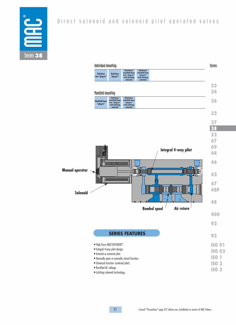
Series 38
• High force MACSOLENOID®.• Integral 4-way pilot design.• Internal or external pilot.• Normally open or normally closed function.• Universal function (external pilot).• Rectified AC voltage.• Latching solenoid technology.
1 2 3
Solenoid
Manual operator
Integral 4-way pilot
Air returnBonded spool
Manifold base“plug-in”
Sub-base/manifold basenon “plug-in” with latching
solenoid
Sub-base/manifold base
“plug-in” with latching
solenoid
Manifold mounting

Function Port size Flow (Max) Individual mounting Series
OPERATIONAL BENEFITS
D i r e c t s o l e n o i d a n d s o l e n o i d p i l o t o p e r a t e d v a l v e s
H O W T O O R D E R
53 Consult “Precautions” page 327 before use, installation or service of MAC Valves..
36
32
3738
3334
5267
46
44
47
42
400
48
92
93
ISO 1ISO 2 ISO 3
69
48P
ISO 01ISO 02
Series 38
3/2 NO-NC 1/8” 1.2 Cv Sub-basenon “plug-in”
1. 3-way valve with 4-way integral pilot.2. 10 mm valve (stacks on 16.5 mm centers).3. High flow (up to 1.2 Cv).4. Fast, repeatable response times.5. Maximum shifting forces in both directions.
38B-XMX-XAX-GXXX-XXX
O P T I O N S
A Individual base – Side portB Individual base – Bottom port
M Pilot exhaust muffledP Pilot exhaust piped (# 10-32)U Pilot exhaust to main exhaust
NO valve
38B-BMA-000-GXXX-XXX
38B-BMB-000-GXXX-XXX
38B-BMA-AAL-GXXX-XXX
38B-BMB-AAM-GXXX-XXX
NC valve
38B-AMA-000-GXXX-XXX
38B-AMB-000-GXXX-XXX
38B-AMA-AAL-GXXX-XXX
38B-AMB-AAM-GXXX-XXX
Universal valve
38B-GMB-000-GXXX-XXX
38B-GMB-AAM-GXXX-XXX
Port size
Valve less base
1/8” NPTF
Pilot air
Internal
External
Internal
External
Note : Above codes are for side port.
G XXX-XXX *STANDARD SOLENOID OPERATOR �
Pilot/Base Configuration :
Voltage
AA 120 VAC (2.5W)DA 24 VDC (1.0W)DC 24 VDC (1.8W)DD 24 VDC (2.5W)DF 24 VDC (4.0W)
Wire length
A 18”B 24”C 36”
Manual operator
1 Non-locking recessed2 Locking recessed
Electrical connection
BA Flying leadsBT Flying leads with lightGA MAC JAC Solenoid plug-inGB MAC JAC Solenoid plug-in
w/DiodeGC MAC JAC Solenoid plug-in
w/MOVGD MAC JAC Solenoid plug-in
w/LEDGE MAC JAC Solenoid plug-in
w/Diode & LEDGF MAC JAC Solenoid plug-in
w/MOV & LEDGG MAC JAC Solenoid plug-in
w/RectifierGH MAC JAC Solenoid plug-in
w/Rectifier & LEDKA Plug-in wire assemblyKT Plug-in wire assembly with
lightKD Plug-in wire assembly with
rectifier & light & ground
XX X X XX
Note : AC voltage requires connector with rectifier.* Other options available, see page 311.Latching solenoid also available, see page 59.With MAC JAC electrical connector washdown capability is possible.Consult factory for modification number.
2 1210
13
21210
13
21210
13

23.3
8.0
116.9
97.6
Ø 5.3
19.0
31.5
44.3
28.4
4.3
46.4
83.0
9.7
4.34.8
16.6
12.0
86.0
MO
DEL
AU
CKLA
ND
, N.Z.
LIEGE, BELG
IUM
WIXO
M, M
I. USA
MO
DIF.
VAC
TO 150 PSI
31
EP
P
2
10
1818100%100%
100%100% M O N T H S
WARRANTY
O FP R O D U C T I O N
T E S T E D
D I M E N S I O N S
T E C H N I C A L D A T A
Dimensions shown are metric (mm)
54 Consult “Precautions” page 327 before use, installation or service of MAC Valves..
Series 38
Fluid :
Pressure range :
Pilot pressure :
Lubrication :
Filtration :
Temperature range :
Flow :
Coil :
Voltage range :
Power :
Response times :
(with 4 W coil)
Compressed air, vacuum, inert gases
Internal Pilot : 20 to 120 PSI
External Pilot : Vacuum to 120 PSI
20 to 120 PSI
Not required, if used select a medium aniline point lubricant (between 180°F and 210°F)
40 µ
0°F to 120°F (-18°C to +50°C)
1/8" bottom port: (1.2 Cv) - 1/8" side port: (1.0 Cv)
Class A wire (#22 AWG x 18), continuous duty
-15% to +10% of nominal voltage
1.0 to 4.0 W
Energize : 6 ms
De-energize : 6 ms
• BSPP threadsOptions :

Function Port size Flow (Max) Individual mounting Series
OPERATIONAL BENEFITS
D i r e c t s o l e n o i d a n d s o l e n o i d p i l o t o p e r a t e d v a l v e s
H O W T O O R D E R
55 Consult “Precautions” page 327 before use, installation or service of MAC Valves..
36
32
3738
3334
5267
46
44
47
42
400
48
92
93
ISO 1ISO 2 ISO 3
69
48P
ISO 01ISO 02
Series 38
3/2 NO-NC 1/8” - 1.2 Cv1/4” O.D. tube receptacle
Sub-base“plug-in”
1. 3-way valve with 4-way integral pilot.2. 10 mm valve (stacks on 16.5 mm centers).3. High flow (up to 1.2 Cv).4. Fast, repeatable response times.5. Maximum shifting forces in both directions.
38B-XMX-XAX-GXX P-XXX
O P T I O N S
A Individual base – Side portB Individual base – Bottom port
M Pilot exhaust muffledP Pilot exhaust piped (# 10-32)U Pilot exhaust to main exhaust
NO valve
38B-BMA-000-GXXP-XXX
38B-BMB-000-GXXP-XXX
38B-BMA-AAA-GXXP-XXX
38B-BMB-AAB-GXXP-XXX
38B-BMA-EAA-GXXP-XXX
38B-BMB-EAB-GXXP-XXX
NC valve
38B-AMA-000-GXXP-XXX
38B-AMB-000-GXXP-XXX
38B-AMA-AAA-GXXP-XXX
38B-AMB-AAB-GXXP-XXX
38B-AMA-EAA-GXXP-XXX
38B-AMB-EAB-GXXP-XXX
Universal valve
38B-GMB-000-GXXP-XXX
38B-GMB-BAB-GXXP-XXX
38B-GMB-EAB-GXXP-XXX
Port size
Valve less base
1/8” NPTF
1/4” O.D.
Tube receptacle
Pilot air
Internal
External
Internal
External
Internal
External
Note : Above codes are for side port.
Voltage
AA 120 VAC (2.5W)DA 24 VDC (1.0W)DC 24 VDC (1.8W)DD 24 VDC (2.5W)DF 24 VDC (4.0W)
Manual operator
1 Non-locking recessed2 Locking recessed
Electrical connection
SA Base plug-inSJ Base plug-in with lightSS Base plug-in with rectifier & light & ground
G XX P-XXX *STANDARD SOLENOID OPERATOR �
XX X XX
Note : AC voltage requires connector with rectifier.* Other options available, see page 311.Latching solenoid also available, see page 61.
Pilot/Base Configuration :
2 1210
13
21210
13
21210
13
Washdown capability is possible, consult factory for modification number.

131.0
9.7
4.0
115.8
6.4
50.4
VAC
TO 150 PSI
MO
DIF.
AU
CKLA
ND
, N.Z.
LIEGE, BELG
IUM
WIXO
M, M
I. USA
MO
DEL
23.3
8.0
2
76.0
31.5
1818100%100%
100%100% M O N T H S
WARRANTY
O FP R O D U C T I O N
T E S T E D
D I M E N S I O N S
T E C H N I C A L D A T A
Dimensions shown are metric (mm)
56 Consult “Precautions” page 327 before use, installation or service of MAC Valves..
Series 38
Fluid :
Pressure range :
Pilot pressure :
Lubrication :
Filtration :
Temperature range :
Flow :
Coil :
Voltage range :
Power :
Response times :
(with 4 W coil)
Compressed air, vacuum, inert gases
Internal Pilot : 20 to 120 PSI
External Pilot : Vacuum to 120 PSI
20 to 120 PSI
Not required, if used select a medium aniline point lubricant (between 180°F and 210°F)
40 µ
0°F to 120°F (-18°C to +50°C)
1/8" bottom port: (1.2 Cv) - 1/8" side port: (1.0 Cv) - 1/4” tube receptacle: (0.85 Cv)
Class A continuous duty, #22 AWG x 12 base leads
-15% to +10% of nominal voltage
1.0 to 4.0 W
Energize : 6 ms
De-energize : 6 ms
• BSPP threadsOptions :

Function Port size Flow (Max) Manifold mounting Series
OPERATIONAL BENEFITS
D i r e c t s o l e n o i d a n d s o l e n o i d p i l o t o p e r a t e d v a l v e s
H O W T O O R D E R
57 Consult “Precautions” page 327 before use, installation or service of MAC Valves..
36
32
3738
3334
5267
46
44
47
42
400
48
92
93
ISO 1ISO 2 ISO 3
69
48P
ISO 01ISO 02
Series 38
3/2 NO-NC 1/8” - 1.2 Cv1/4” O.D. tube receptacle
Manifold base“plug-in”
1. 3-way valve with 4-way integral pilot.2. 10 mm valve (stacks on 16.5 mm centers).3. High flow (up to 1.2 Cv).4. Fast, repeatable response times.5. Maximum shifting forces in both directions.
38B-XXX-XJX-GXX P-XXX
O P T I O N S
J Manifold base – Side portK Manifold base – Bottom portL Left end manifold base – Side portM Left end manifold base – Bottom portN Right end manifold base – Side portP Right end manifold base – Bottom port
Note : Manifold assemblies consist of (1) left end manifold, (1) right end manifold and middle station manifolds (options "J" or "K").
NO valve
38B-BMA-000-GXXP-XXX
38B-BMB-000-GXXP-XXX
38B-BMA-AJA-GXXP-XXX
38B-BMB-AJB-GXXP-XXX
38B-BMA-EJA-GXXP-XXX
38B-BMB-EJB-GXXP-XXX
NC valve
38B-AMA-000-GXXP-XXX
38B-AMB-000-GXXP-XXX
38B-AMA-AJA-GXXP-XXX
38B-AMB-AJB-GXXP-XXX
38B-AMA-EJA-GXXP-XXX
38B-AMB-EJB-GXXP-XXX
Universal valve
38B-GMB-000-GXXP-XXX
38B-GMB-BJB-GXXP-XXX
38B-GMB-EJB-GXXP-XXX
Port size
Valve less base
1/8” NPTF
1/4” O.D.
Tube receptacle
Pilot air
Internal
External
Internal
External
Internal
External
Note : Above codes are for side port.
Voltage
AA 120 VAC (2.5W)DA 24 VDC (1.0W)DC 24 VDC (1.8W)DD 24 VDC (2.5W)DF 24 VDC (4.0W)
Manual operator
1 Non-locking recessed2 Locking recessed
Electrical connection
SA Base plug-inSJ Base plug-in with lightSS Base plug-in with rectifier & light & ground
G XX P-XXX *STANDARD SOLENOID OPERATOR �
XX X XX
Note : AC voltage requires connector with rectifier.* Other options available, see page 311.Latching solenoid also available, see page 61.Washdown capability is possible, consult factory for modification number.
Base Configuration :
38B-000-XXX(i.e. 38B-000-AJA)
Base only :
2 1210
13
21210
13
21210
13

1818100%100%
100%100% M O N T H S
WARRANTY
O FP R O D U C T I O N
T E S T E D
D I M E N S I O N S
T E C H N I C A L D A T A
Dimensions shown are metric (mm)
58 Consult “Precautions” page 327 before use, installation or service of MAC Valves..
Series 38
CONDUIT3/4"-14
51.5
16.523.3
2222
47.5
55.5
33.529.5
12.016.7
107.1
82.372.7
28.4
TYP.
TYP.
TYP.4.0
9.7
TYP.TYP.
TYP.23.3
16.531.5
8.0
VA
C T
O 150 P
SI
MO
DIF
.
AU
CK
LAN
D, N
.Z.
LIEG
E, B
ELG
IUM
WIX
OM
, MI. U
SA
MO
DE
L
2
Ø 5.3TYP.
1/4" O.D. TUBE FITTING1/8" TAPPED OR
3/8" IN & EXH
EXT. PILOT1/8" COMMON
1/4" O.D. TUBE FITTING1/8" TAPPED OR
131.0115.8
MO
DE
L
AU
CK
LAN
D, N
.Z.
LIEG
E, B
ELG
IUM
WIX
OM
, MI. U
SA
MO
DIF
.V
AC
TO
150 PS
I
VA
C T
O 150 P
SI
MO
DIF
.
AU
CK
LAN
D, N
.Z.
LIEG
E, B
ELG
IUM
WIX
OM
, MI. U
SA
MO
DE
L
2
1
3
EP
CO
ND
22
MO
DE
L
AU
CK
LAN
D, N
.Z.
LIEG
E, B
ELG
IUM
WIX
OM
, MI. U
SA
MO
DIF
.V
AC
TO
150 PS
I
76.0
Fluid :
Pressure range :
Pilot pressure :
Lubrication :
Filtration :
Temperature range :
Flow :
Coil :
Voltage range :
Power :
Response times :
(with 4 W coil)
Compressed air, vacuum, inert gases
Internal Pilot : 20 to 120 PSI
External Pilot : Vacuum to 120 PSI
20 to 120 PSI
Not required, if used select a medium aniline point lubricant (between 180°F and 210°F)
40 µ
0°F to 120°F (-18°C to +50°C)
1/8" bottom port: (1.2 Cv) - 1/8" side port: (1.0 Cv) - 1/4” tube receptacle: (0.85 Cv)
Class A continuous duty, #22 AWG x 12 base leads
-15% to +10% of nominal voltage
1.0 to 4.0 W
Energize : 6 ms
De-energize : 6 ms
• BSPP threadsOptions :

OPERATIONAL BENEFITS
D i r e c t s o l e n o i d a n d s o l e n o i d p i l o t o p e r a t e d v a l v e s
H O W T O O R D E R
59 Consult “Precautions” page 327 before use, installation or service of MAC Valves..
36
32
3738
3334
5267
46
44
47
42
400
48
92
93
ISO 1ISO 2 ISO 3
69
48P
ISO 01ISO 02
Series 38
Function Port size Flow (Max) Individual/Manifold mounting Series
3/2 NO-NC 1/8” - 1.2 Cv1/4” O.D. tube receptacle
Sub-base/manifold basenon “plug-in” with latching
solenoid
1. 3-way valve with 4-way integral pilot.2. 10 mm valve (stacks on 16.5 mm centers).3. High flow (up to 1.2 Cv).4. Fast, repeatable response times.5. Maximum shifting forces in both directions.
38A-XMX-XAX-LXXX-XXX
O P T I O N S
A Individual base – Side portB Individual base – Bottom portJ Manifold base – Side portK Manifoldl base – Bottom port
M Pilot exhaust muffledP Pilot exhaust piped (#10-32)U Pilot exhaust to main exhaust
Note : Above codes are for individual base and side port.
L XXX-XXX *LATCHING SOLENOID OPERATOR �
* Other options available, see page 319.** Latching 38 series with non plug-in base configuration must use "B", "K" or "L" type electrical connector.
Note : Manifold assemblies require an end plate kit : M-38003-01-01 (internal pilot)M-38003-02-01 (external pilot)
Pilot/Base Configuration :
Voltage
DF 24 VDC (4.0W)HA 24 VDC (1.95W)
Wire length
A 18”B 24”C 36”
Manual operator
0 No operator
Electrical connection**
BA 2 Wire Flying leadsBJ 4 Wire Flying leads KA 2 Wire Plug-in AssemblyKE 4 Wire Plug-in AssemblyLA 3 Wire plug-in assembly
(Polarity Switching Cover)
XX X X XX
NO valve
38A-BMA-000-LXXX-XXX
38A-BMB-000-LXXX-XXX
38A-BMA-AAL-LXXX-XXX
38A-BMB-AAM-LXXX-XXX
38A-BMA-EAL-LXXX-XXX
38A-BMB-EAM-LXXX-XXX
NC valve
38A-AMA-000-LXXX-XXX
38A-AMB-000-LXXX-XXX
38A-AMA-AAL-LXXX-XXX
38A-AMB-AAM-LXXX-XXX
38A-AMA-EAL-LXXX-XXX
38A-AMB-EAM-LXXX-XXX
Universal valve
38A-GMB-000-LXXX-XXX
38A-GMB-AAM-LXXX-XXX
38A-GMB-EAM-LXXX-XXX
Port size
Valve less base
1/8” NPTF
1/4” O.D.
Tube receptacle
Pilot air
Internal
External
Internal
External
Internal
External
21210
13
21210
13
2 12
13
10
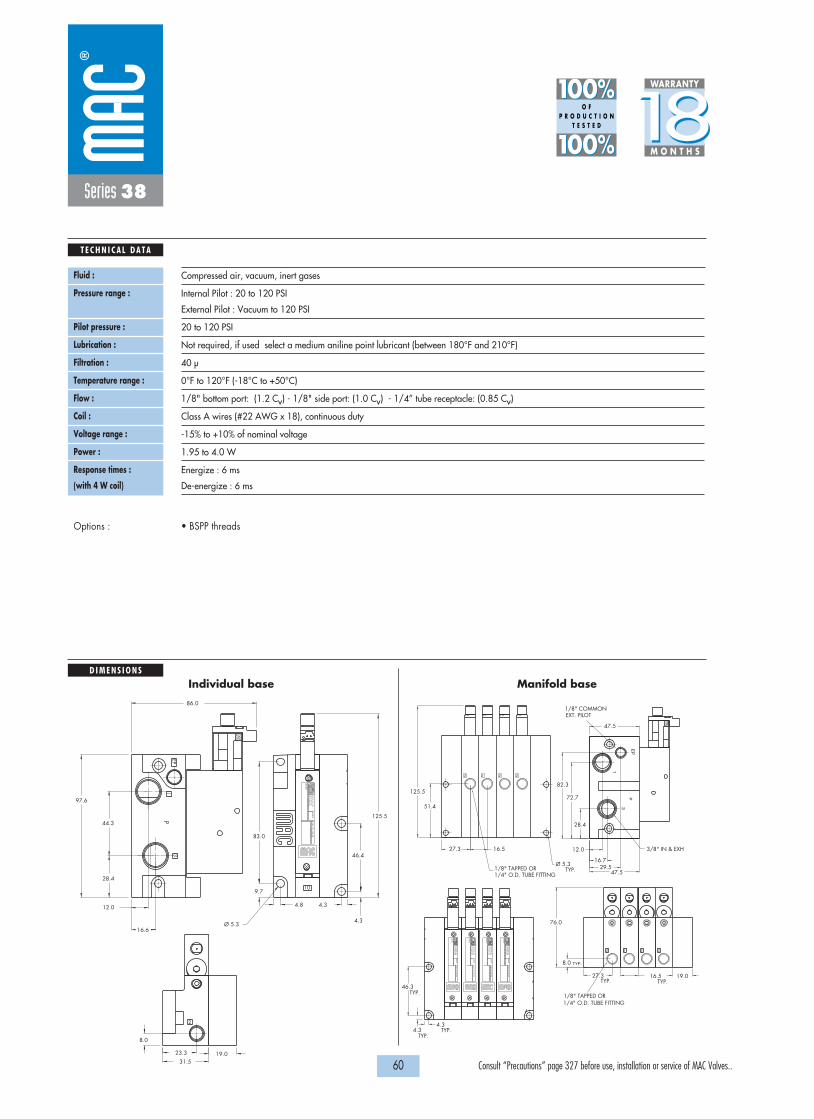
1818100%100%
100%100% M O N T H S
WARRANTY
O FP R O D U C T I O N
T E S T E D
D I M E N S I O N S
T E C H N I C A L D A T A
60 Consult “Precautions” page 327 before use, installation or service of MAC Valves..
Series 38
VAC
TO 150 PSI
MO
DIF.
AU
CKLA
ND
, N.Z.
LIEGE, BELG
IUM
WIXO
M, M
I. USA
MO
DEL
86.0
12.0
16.6
4.8 4.3
9.7
83.0
46.4
4.3
28.4
44.3
31.519.0
Ø 5.3
97.6
8.0
23.3
125.5
10
2
PEP
13
125.5
51.4
27.3
19.027.3
46.3
4.34.3
EP
1
3
P
TYP.Ø 5.3
16.5
82.3
72.7
28.4
47.5
47.529.5
16.7
12.0
TYP.TYP.
TYP.
TYP. TYP.
TYP.
16.5
8.0
76.0
2222
VA
C T
O 150 P
SI
MO
DIF
.
AU
CK
LAN
D, N
.Z.
LIEG
E, B
ELG
IUM
WIX
OM
, MI. U
SA
MO
DE
L
2
1/4" O.D. TUBE FITTING1/8" TAPPED OR
3/8" IN & EXH
EXT. PILOT1/8" COMMON
1/4" O.D. TUBE FITTING1/8" TAPPED OR
22 2
MO
DE
L
AU
CK
LAN
D, N
.Z.
LIEG
E, B
ELG
IUM
WIX
OM
, MI. U
SA
MO
DIF
.V
AC
TO
150 PS
I
MO
DE
L
AU
CK
LAN
D, N
.Z.
LIEG
E, B
ELG
IUM
WIX
OM
, MI. U
SA
MO
DIF
.V
AC
TO
150 PS
I
MO
DE
L
AU
CK
LAN
D, N
.Z.
LIEG
E, B
ELG
IUM
WIX
OM
, MI. U
SA
MO
DIF
.V
AC
TO
150 PS
I
Fluid :
Pressure range :
Pilot pressure :
Lubrication :
Filtration :
Temperature range :
Flow :
Coil :
Voltage range :
Power :
Response times :
(with 4 W coil)
Compressed air, vacuum, inert gases
Internal Pilot : 20 to 120 PSI
External Pilot : Vacuum to 120 PSI
20 to 120 PSI
Not required, if used select a medium aniline point lubricant (between 180°F and 210°F)
40 µ
0°F to 120°F (-18°C to +50°C)
1/8" bottom port: (1.2 Cv) - 1/8" side port: (1.0 Cv) - 1/4” tube receptacle: (0.85 Cv)
Class A wires (#22 AWG x 18), continuous duty
-15% to +10% of nominal voltage
1.95 to 4.0 W
Energize : 6 ms
De-energize : 6 ms
• BSPP threadsOptions :
Individual base Manifold base

OPERATIONAL BENEFITS
D i r e c t s o l e n o i d a n d s o l e n o i d p i l o t o p e r a t e d v a l v e s
H O W T O O R D E R
61 Consult “Precautions” page 327 before use, installation or service of MAC Valves..
36
32
3738
3334
5267
46
44
47
42
400
48
92
93
ISO 1ISO 2 ISO 3
69
48P
ISO 01ISO 02
Series 38
Function Port size Flow (Max) Individual/Manifold mounting Series
3/2 NO-NC 1/8” - 1.2 Cv1/4” O.D. tube receptacle
Sub-base/manifold base
“plug-in” with latching
solenoid
1. 3-way valve with 4-way integral pilot.2. 10 mm valve (stacks on 16.5 mm centers).3. High flow (up to 1.2 Cv).4. Fast, repeatable response times.5. Maximum shifting forces in both directions.
Voltage
DF 24 VDC (4.0W)HA 24 VDC (1.95W)
Manual operator
0 No operator
Electrical connection**
DA Base/Manifold Plug-inDB Base/Manifold Plug-in w/GroundDC Base/Manifold Plug-in w/ LedDD Base/Manifold Plug-in w/ Led and GroundEA Base/Manifold Plug-in 3 Pin
(Polarity Switching Cover)
L XX P-XXX *LATCHING SOLENOID OPERATOR �
XX X XX
38A-XXX-XAX-LXXP-XXX
O P T I O N S
A Individual base – Side portB Individual base – Bottom portJ Manifold base – Side portK Manifold base – Bottom portL Left end manifold base – Side portM Left end manifold base – Bottom portN Right end manifold base – Side portP Right end manifold base – Bottom port
* Other options available, see page 319.** 2 and 4 wire bases must use "D" type electrical connector.
3 wire base must use "EA" type electrical connector.
Note : Manifold assemblies consist of (1) left end manifold, (1) right end manifold, and middle station manifolds (option J or K).
Manifold/Base Configuration :
38A-XXX-XXA-LXXP-XXX
A Plug-In Int. Pilot (2 Wire)**B Plug-In Ext. Pilot (2 Wire)**C Plug-In Int. Pilot (3 Wire)**D Plug-In Ext. Pilot (3 Wire)**E Plug-In Int. Pilot (4 Wire)**F Plug-In Ext. Pilot (4 Wire)**
Manifold/Base Int./Ext. Pilot : (Wire options)
Note : Above codes are for individual base and side port.
NO valve
38A-BMA-000-LXXP-XXX
38A-BMB-000-LXXP-XXX
38A-BMA-AAA-LXXP-XXX
38A-BMB-AAB-LXXP-XXX
38A-BMA-EAA-LXXP-XXX
38A-BMB-EAB-LXXP-XXX
NC valve
38A-AMA-000-LXXP-XXX
38A-AMB-000-LXXP-XXX
38A-AMA-AAA-LXXP-XXX
38A-AMB-AAB-LXXP-XXX
38A-AMA-EAA-LXXP-XXX
38A-AMB-EAB-LXXP-XXX
Universal valve
38A-GMB-000-LXXP-XXX
38A-GMB-AAB-LXXP-XXX
38A-GMB-EAB-LXXP-XXX
Port size
Valve less base
1/8” NPTF
1/4” O.D.
Tube receptacle
Pilot air
Internal
External
Internal
External
Internal
External
21210
13
21210
13
2 12
13
10

1818100%100%
100%100% M O N T H S
WARRANTY
O FP R O D U C T I O N
T E S T E D
D I M E N S I O N S
T E C H N I C A L D A T A
Dimensions shown are metric (mm)
62 Consult “Precautions” page 327 before use, installation or service of MAC Valves..
Series 38
50.4
6.4
115.8
4.0
9.7
131.0
MO
DEL
AU
CKLA
ND
, N.Z.
LIEGE, BELG
IUM
WIXO
M, M
I. USA
MO
DIF.
VAC
TO 150 PSI
8.0
23.3
2
31.5
76.0
Fluid :
Pressure range :
Pilot pressure :
Lubrication :
Filtration :
Temperature range :
Flow :
Coil :
Voltage range :
Power :
Response times :
(with 4 W coil)
Compressed air, vacuum, inert gases
Internal Pilot : 20 to 120 PSI
External Pilot : Vacuum to 120 PSI
20 to 120 PSI
Not required, if used select a medium aniline point lubricant (between 180°F and 210°F)
40 µ
0°F to 120°F (-18°C to +50°C)
1/8" bottom port: (1.2 Cv) - 1/8" side port: (1.0 Cv) - 1/4” tube receptacle: (0.85 Cv)
Class A continuous duty, #22 AWG x 12 base leads
-15% to +10% of nominal voltage
1.95 to 4.0 W
Energize : 6 ms
De-energize : 6 ms
• BSPP threadsOptions :
CONDUIT3/4"-14
51.5
16.523.3
2222
47.5
55.5
33.529.5
12.016.7
107.1
82.372.7
28.4
Ø 5.3TYP.
1/4" O.D. TUBE FITTING1/8" TAPPED OR
3/8" IN & EXH
EXT. PILOT1/8" COMMON
1
3
EP
CO
ND
TYP.
TYP.
TYP.4.0
9.7
VA
C T
O 150 P
SI
MO
DIF
.
AU
CK
LAN
D, N
.Z.
LIEG
E, B
ELG
IUM
WIX
OM
, MI. U
SA
MO
DE
L
131.0115.8
MO
DE
L
AU
CK
LAN
D, N
.Z.
LIEG
E, B
ELG
IUM
WIX
OM
, MI. U
SA
MO
DIF
.V
AC
TO
150 PS
I
VA
C T
O 150 P
SI
MO
DIF
.
AU
CK
LAN
D, N
.Z.
LIEG
E, B
ELG
IUM
WIX
OM
, MI. U
SA
MO
DE
L
MO
DE
L
AU
CK
LAN
D, N
.Z.
LIEG
E, B
ELG
IUM
WIX
OM
, MI. U
SA
MO
DIF
.V
AC
TO
150 PS
I
TYP.TYP.
TYP.23.3
16.531.5
8.0
2
1/4" O.D. TUBE FITTING1/8" TAPPED OR
222
76.0
Individual base Manifold base

63 Consult “Precautions” page 327 before use, installation or service of MAC Valves..
Individual mounting Series
D i r e c t s o l e n o i d a n d s o l e n o i d p i l o t o p e r a t e d v a l v e s
SERIES FEATURES
36
32
3738
3334
5267
46
44
47
42
400
48
92
93
ISO 1ISO 2 ISO 3
69
48P
ISO 01ISO 02
Inline
Series 52
• Patented MACSOLENOID® for fastest possible response timesand virtually burn-out proof AC solenoid operation.
• Optional low watt DC solenoids.• Various manual operators.• Optional memory spring.• Normally closed or normally open valve function.• May be plugged for 2-way operation.• Internal or external pilot.
2
13
Air return
Bonded spool
Manual operator
Solenoid
4-way pilot with balanced poppet

64 Consult “Precautions” page 327 before use, installation or service of MAC Valves..
Series 52
SPOOL CONFIGURATIONS
2
3 1
10 122
3 1
10 12
INTERNAL PILOTINTERNAL PILOT
NORMALLY OPEN 3 WAYNORMALLY CLOSED 3 WAY
1818100%100%
100%100% M O N T H S
WARRANTY
O FP R O D U C T I O N
T E S T E D
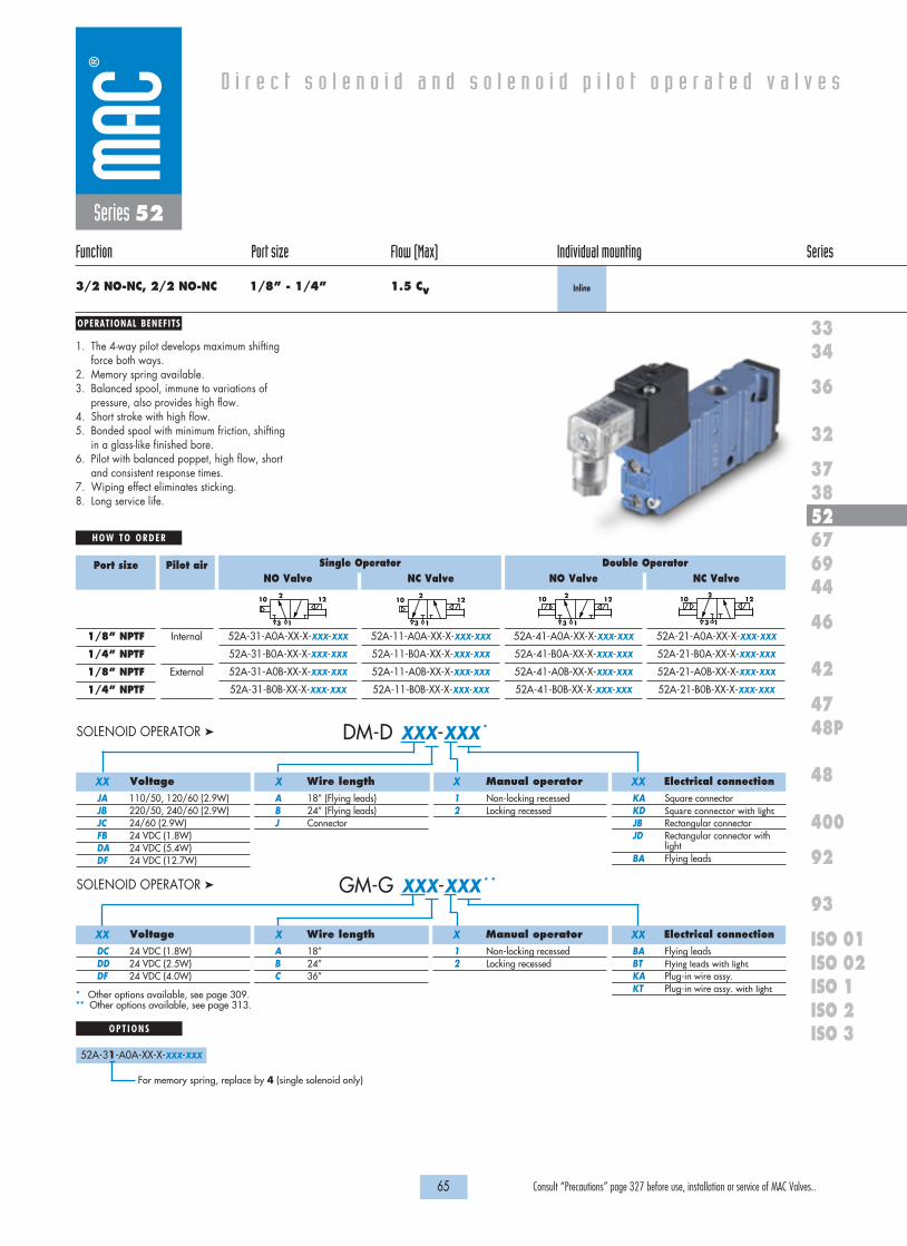
OPERATIONAL BENEFITS
D i r e c t s o l e n o i d a n d s o l e n o i d p i l o t o p e r a t e d v a l v e s
H O W T O O R D E R
65 Consult “Precautions” page 327 before use, installation or service of MAC Valves..
36
32
3738
3334
5267
46
44
47
42
400
48
92
93
ISO 1ISO 2 ISO 3
69
48P
ISO 01ISO 02
NO Valve
52A-31-A0A-XX-X-XXX-XXX
52A-31-B0A-XX-X-XXX-XXX
52A-31-A0B-XX-X-XXX-XXX
52A-31-B0B-XX-X-XXX-XXX
NC Valve
52A-11-A0A-XX-X-XXX-XXX
52A-11-B0A-XX-X-XXX-XXX
52A-11-A0B-XX-X-XXX-XXX
52A-11-B0B-XX-X-XXX-XXX
NO Valve
52A-41-A0A-XX-X-XXX-XXX
52A-41-B0A-XX-X-XXX-XXX
52A-41-A0B-XX-X-XXX-XXX
52A-41-B0B-XX-X-XXX-XXX
NC Valve
52A-21-A0A-XX-X-XXX-XXX
52A-21-B0A-XX-X-XXX-XXX
52A-21-A0B-XX-X-XXX-XXX
52A-21-B0B-XX-X-XXX-XXX
21210
13
2 1210
13
21210
13
2 12
13
10
Port size
1/8” NPTF
1/4” NPTF
1/8” NPTF
1/4” NPTF
Pilot air
Internal
External
Series 52
Function Port size Flow (Max) Individual mounting Series
3/2 NO-NC, 2/2 NO-NC 1/8” - 1/4” 1.5 Cv Inline
1. The 4-way pilot develops maximum shiftingforce both ways.
2. Memory spring available.3. Balanced spool, immune to variations of
pressure, also provides high flow.4. Short stroke with high flow.5. Bonded spool with minimum friction, shifting
in a glass-like finished bore.6. Pilot with balanced poppet, high flow, short
and consistent response times.7. Wiping effect eliminates sticking. 8. Long service life.
DM-D XXX-XXX *SOLENOID OPERATOR �
Voltage
JA 110/50, 120/60 (2.9W)JB 220/50, 240/60 (2.9W)JC 24/60 (2.9W)FB 24 VDC (1.8W)DA 24 VDC (5.4W)DF 24 VDC (12.7W)
Wire length
A 18” (Flying leads)B 24” (Flying leads)J Connector
Manual operator
1 Non-locking recessed2 Locking recessed
Electrical connection
KA Square connectorKD Square connector with lightJB Rectangular connectorJD Rectangular connector with
lightBA Flying leads
XX X X XX
GM-G XXX-XXX * *SOLENOID OPERATOR �
Voltage
DC 24 VDC (1.8W)DD 24 VDC (2.5W)DF 24 VDC (4.0W)
Wire length
A 18”B 24”C 36”
Manual operator
1 Non-locking recessed2 Locking recessed
Electrical connection
BA Flying leadsBT Flying leads with lightKA Plug-in wire assy.KT Plug-in wire assy. with light
XX X X XX
* Other options available, see page 309.** Other options available, see page 313.
O P T I O N S
52A-31-A0A-XX-X-XXX-XXX
Single Operator Double Operator
For memory spring, replace by 4 (single solenoid only)

1818100%100%
100%100% M O N T H S
WARRANTY
O FP R O D U C T I O N
T E S T E D
D I M E N S I O N S
T E C H N I C A L D A T A
Dimensions shown are metric (mm)
66 Consult “Precautions” page 327 before use, installation or service of MAC Valves..
62,5
24,5
17,0
79,0
27,0
21,0
44,0
4,5
25,0
24,0
13,0
15,51,6
#10-32 OR M5(OPTIONAL EXTERNAL
PILOT PORT)
3,25 DIA.THR U, TYP. (2)
Series 52
Fluid :
Pressure range :
Lubrication :
Filtration :
Temperature range :
Flow :
Coil :
Voltage range :
Protection :
Power :
Response times :
Compressed air, vacuum, inert gases
Internal Pilot : 20 to 120 PSI
External Pilot : Vacuum to 120 PSI
Not required, if used select a medium aniline point lubricant (between 180°F and 210°F)
40 µ
0°F to 120°F (-18°C to +50°C)
1/8" : (1.2 Cv) – 1/4" : (1.5 Cv)
Class A continuous duty, #22 AWG x 18 lead wires
-15% to +10% of nominal voltage
Consult factory
~Inrush: 10.9 VA Holding: 7.7 VA
= 1.8 to 12.7 W
24V=/5.4W Energize: 7.3 ms De-energize: 5.3 ms
120/60 Energize: 8-12 ms De-energize: 7-11 ms
• BSPP threadsOptions :
TYP. (2)

67 Consult “Precautions” page 327 before use, installation or service of MAC Valves..
Individual mounting Series
D i r e c t s o l e n o i d a n d s o l e n o i d p i l o t o p e r a t e d v a l v e s
SERIES FEATURES
36
32
3738
3334
5267
46
44
47
42
400
48
92
93
ISO 1ISO 2 ISO 3
69
48P
ISO 01ISO 02
Inline
Series 67
• Patented MACSOLENOID® for fastest possible response timesand virtually burn-out proof AC solenoid operation.
• Optional low watt DC solenoids.• Normally closed or normally open valve function.• Optional universal spool.• Internal or external pilot.• Optional memory spring.• Checked accumulator.• Optional pilot exhaust to main valve exhaust.• May be plugged for 2-way operation.
Inlet (1) Exhaust (3)
Cylinder (2)
Solenoid
Manual operator
4-way pilot with balanced poppet
Air returnBonded spool

OPERATIONAL BENEFITS
D i r e c t s o l e n o i d a n d s o l e n o i d p i l o t o p e r a t e d v a l v e s
H O W T O O R D E R
69 Consult “Precautions” page 327 before use, installation or service of MAC Valves..
36
32
3738
3334
5267
46
44
47
42
400
48
92
93
ISO 1ISO 2 ISO 3
69
48P
ISO 01ISO 02
NO Valve
67A-CX-AAA-DM-DXXX-XXX
67A-CX-BAA-DM-DXXX-XXX
67A-CX-AAB-DM-DXXX-XXX
67A-CX-BAB-DM-DXXX-XXX
NC Valve
67A-AX-AAA-DM-DXXX-XXX
67A-AX-BAA-DM-DXXX-XXX
67A-AX-AAB-DM-DXXX-XXX
67A-AX-BAB-DM-DXXX-XXX
NO Valve
67A-DX-AAA-DM-DXXX-XXX
67A-DX-BAA-DM-DXXX-XXX
67A-DX-AAB-DM-DXXX-XXX
67A-DX-BAB-DM-DXXX-XXX
NC Valve
67A-BX-AAA-DM-DXXX-XXX
67A-BX-BAA-DM-DXXX-XXX
67A-BX-AAB-DM-DXXX-XXX
67A-BX-BAB-DM-DXXX-XXX
21210
13
2 1210
13
21210
13
2 12
13
10
Port size
3/4” NPTF
1” NPTF
3/4” NPTF
1” NPTF
Pilot air
Internal
External
Series 67
Function Port size Flow (Max) Individual mounting Series
3/2 NO-NC, 2/2 NO-NC 3/4” - 1” 20.0 Cv Inline
1. The 4-way pilot develops maximum shiftingforce both ways.
2. Memory spring available.3. Balanced spool, immune to variations of
pressure, also provides high flow.4. Short stroke with high flow.5. Bonded spool with minimum friction, shifting
in a glass-like finished bore.6. Pilot with balanced poppet, high flow, short
and consistent response times.7. Wiping effect eliminates sticking.
DM-D XXX-XXX *SOLENOID OPERATOR �
Voltage
JA 110/50, 120/60 (2.9W)JB 220/50, 240/60 (2.9W)JC 24/60 (2.9W)FB 24 VDC (1.8W)DA 24 VDC (5.4W)DF 24 VDC (12.7W)
Wire length
A 18”B 24”J Connector
Manual operator
1 Non-locking recessed2 Locking recessed
Electrical connection
KA Square connectorKD Square connector with lightJB Rectangular connectorJD Rectangular connector with
lightBA Flying leads
XX X X XX
* Other options available, see page 309.
O P T I O N S
67A-XX-AAA-DM-DXXX-XXX
Single Operator Double Operator
G Single operator universal spoolH Double operator universal spool
Spool type :
67A-XX-AXA-DM-DXXX-XXX
A Standard pilot exhaustB Pilot exhaust to main exhaust*C Pilot exhaust out adapter** Must use DU pilot. Replace DM with DU
Port configuration :
67A-XX-AAA-DM-DXXX-XXX
1 Standard return2 Standard return with memory spring
(for use with single operator only)
Spool return :
67A-XX-AAA-DM-DXXX-XXX
M Pilot exhaust muffledP Pilot exhaust piped (#10-32)U Pilot exhaust to main exhaust
Pilot style :
67A-XX-XAA-DM-DXXX-XXX
G O-Ring mount
Mounting style :
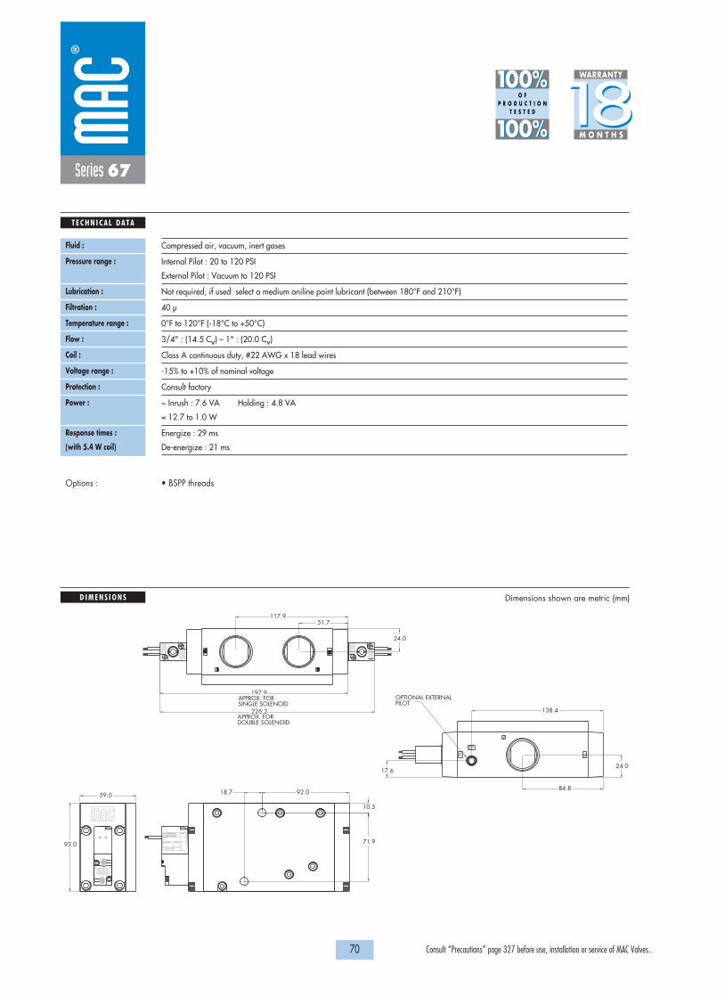
10103311
1212
SINGLE SOLENOIDAPPROX. FOR
DOUBLE SOLENOIDAPPROX. FOR
VAC TO 120 PSI
WATTSELECTRICAL
MODELAUCKLAND,N.Z.LIEGE,BELGIUMWIXOM,MI.USA MODIF.
197.9
226.2
59.0
93.0
10
12
EP
2
51.7
24.0
PILOTOPTIONAL EXTERNAL
92.018.7
10.5
71.9
24.0
84.8
117.9
138.4
17.6
1818100%100%
100%100% M O N T H S
WARRANTY
O FP R O D U C T I O N
T E S T E D
D I M E N S I O N S
T E C H N I C A L D A T A
Dimensions shown are metric (mm)
70 Consult “Precautions” page 327 before use, installation or service of MAC Valves..
Series 67
Fluid :
Pressure range :
Lubrication :
Filtration :
Temperature range :
Flow :
Coil :
Voltage range :
Protection :
Power :
Response times :
(with 5.4 W coil)
Compressed air, vacuum, inert gases
Internal Pilot : 20 to 120 PSI
External Pilot : Vacuum to 120 PSI
Not required, if used select a medium aniline point lubricant (between 180°F and 210°F)
40 µ
0°F to 120°F (-18°C to +50°C)
3/4" : (14.5 Cv) – 1" : (20.0 Cv)
Class A continuous duty, #22 AWG x 18 lead wires
-15% to +10% of nominal voltage
Consult factory
~ Inrush : 7.6 VA Holding : 4.8 VA
= 12.7 to 1.0 W
Energize : 29 ms
De-energize : 21 ms
• BSPP threadsOptions :
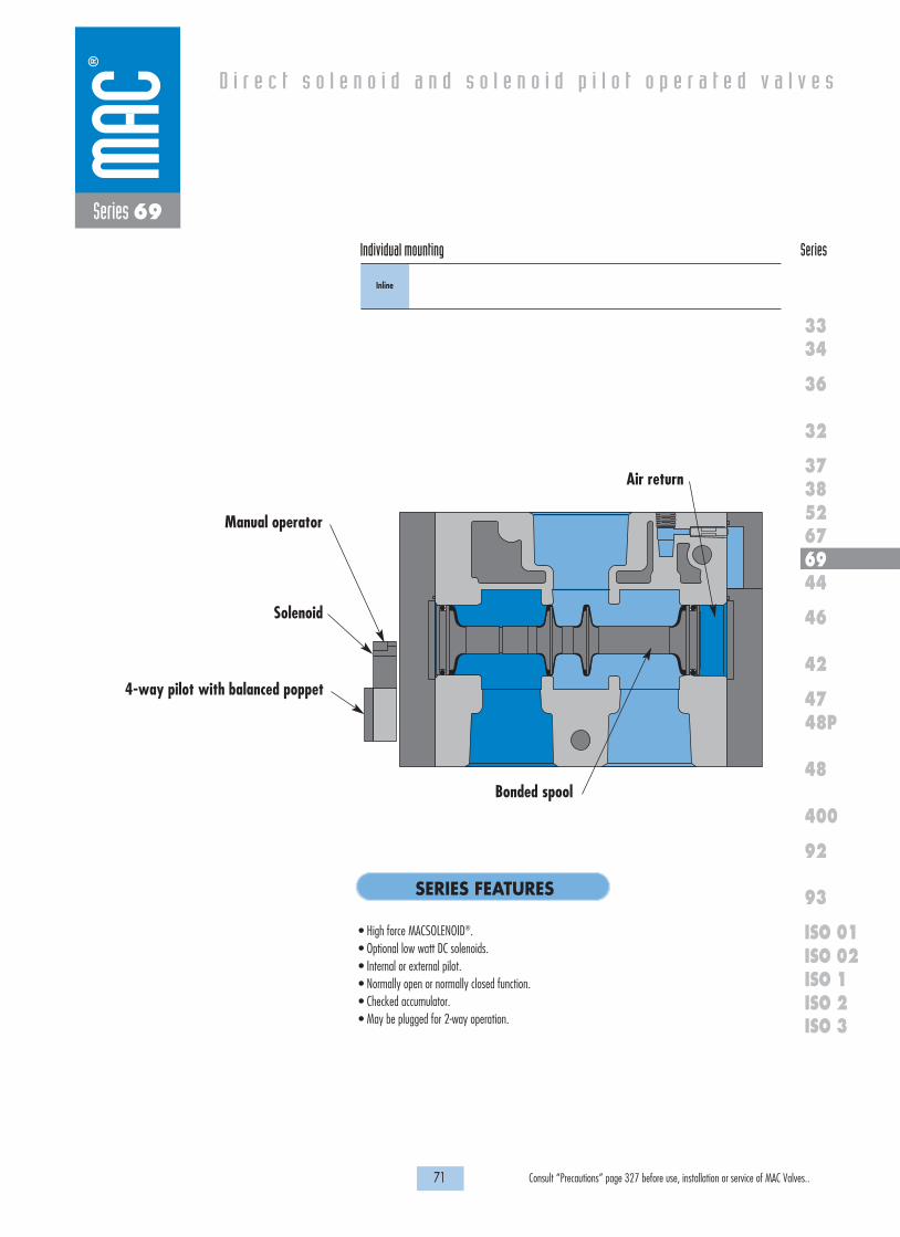
71 Consult “Precautions” page 327 before use, installation or service of MAC Valves..
Individual mounting Series
D i r e c t s o l e n o i d a n d s o l e n o i d p i l o t o p e r a t e d v a l v e s
SERIES FEATURES
36
32
3738
3334
5267
46
44
47
42
400
48
92
93
ISO 1ISO 2 ISO 3
69
48P
ISO 01ISO 02
Inline
Series 69
• High force MACSOLENOID®.• Optional low watt DC solenoids.• Internal or external pilot.• Normally open or normally closed function.• Checked accumulator.• May be plugged for 2-way operation.
Air return
Bonded spool
Manual operator
Solenoid
4-way pilot with balanced poppet

OPERATIONAL BENEFITS
D i r e c t s o l e n o i d a n d s o l e n o i d p i l o t o p e r a t e d v a l v e s
H O W T O O R D E R
73 Consult “Precautions” page 327 before use, installation or service of MAC Valves..
36
32
3738
3334
5267
46
44
47
42
400
48
92
93
ISO 1ISO 2 ISO 3
69
48P
ISO 01ISO 02
Series 69
Function Port size Flow (Max) Individual mounting Series
3/2 NO-NC, 2/2 NO-NC 1 1/2” - 2” - 2 1/2” 60.0 Cv Inline
1. The 4-way pilot develops maximum shiftingforce both ways.
2. Balanced spool, immune to variations ofpressure, also provides high flow.
3. Short stroke with high flow.4. Bonded spool with minimum friction, shifting
in a glass-like finished bore.5. Pilot with balanced poppet, high flow, short
and consistent response times.6. Wiping effect eliminates sticking and
contamination.
Single OperatorNC valve
69A-A1-AAA-JXXX-XXX
69A-A1-BAA-JXXX-XXX
69A-A1-CAA-JXXX-XXX
69A-A1-AAB-JXXX-XXX
69A-A1-BAB-JXXX-XXX
69A-A1-CAB-JXXX-XXX
Single OperatorNO valve
69A-C1-AAA-JXXX-XXX
69A-C1-BAA-JXXX-XXX
69A-C1-CAA-JXXX-XXX
69A-C1-AAB-JXXX-XXX
69A-C1-BAB-JXXX-XXX
69A-C1-CAB-JXXX-XXX
Port size
1 1/2"
2"
2 1/2"
1 1/2"
2"
2 1/2"
Pilot air
Internal
External
69A-xx-xx X-JXXX-XXX
O P T I O N S
A Standard pilot exhaustB Pilot exhaust out main exhaust
J XXX-XXX * (-G) Add “G” for ground SOLENOID OPERATOR �
* Other options available, see page 317.Note : use “0” No lead wire for “J”, “K” and “L” type electrical connectors.
AC voltage requires connector with rectifier.
Pilot exhaust configuration:
Voltage
AA 120 VAC (5,4W)DA 24 VDC (5,4W)DB 12 VDC (5,4W)DC 24 VDC (2,4W)DD 12 VDC (2,4W)
Lead wire length
0 No lead wireA 18”B 24”C 36”
Manual operator
1 Non-locking2 Locking
Electrical connection*
BA Flying leadsGA MAC JAC Solenoid Plug-inGG MAC JAC Solenoid Plug-in
with rectifierJB Rectangular connectorJD Rectangular connector with lightKA Mini square connectorKD Mini square connector with light
XX X X XX
21210
13
2 1210
13
M Manifold O’Ring Mount

3
1
12
101
0
12
2EP
50.5
129.1
101.0119.8
19.545.8
151.8
161.2
Ø 13.0
37.6129.1
215.6
8.822.8
281.3
80.1
178.1
50.5
SHOWN2 1/2" PORTS
81.1129.1
177.1
59.8121.8
181.5
EXHAUST1/8" PILOT
1818100%100%
100%100% M O N T H S
WARRANTY
O FP R O D U C T I O N
T E S T E D
D I M E N S I O N S
T E C H N I C A L D A T A
Dimensions shown are metric (mm)
74 Consult “Precautions” page 327 before use, installation or service of MAC Valves..
Series 69
Fluid :
Pressure range :
Pilot Pressure:
Lubrication :
Filtration :
Temperature range :
Flow :
Coil :
Voltage range :
Power :
Compressed air, vacuum, inert gases
Internal Pilot : 20 to 120 PSI
External Pilot : Vacuum to 120 PSI
20 to 120 PSI
Not required, if used select a medium aniline point lubricant (between 180°F and 210°F)
40 µ
0°F to 120°F (-18°C to +50°C)
Cv 60.0
Class A wire, #22 AWG x 18, continuous duty
-15% to +10% of nominal voltage
5.4W – 2.4W – 1.8W
• BSPP threadsOptions :

75 Consult “Precautions” page 327 before use, installation or service of MAC Valves..
Individual mounting Series
D i r e c t s o l e n o i d a n d s o l e n o i d p i l o t o p e r a t e d v a l v e s
SERIES FEATURES
36
32
3738
3334
5267
46
44
47
42
400
48
92
93
ISO 1ISO 2 ISO 3
69
48P
ISO 01ISO 02
Inline
Series 44
• High force MACSOLENOID®.• 10mm direct operated.• # 10-32 or M5 ports.• Rated for lubricated or non-lubricated service.
EAIN
EB
BA
Manual operator
Armature
Coil
Push Pin
Valve spring
“D” seal 4 Balanced poppets
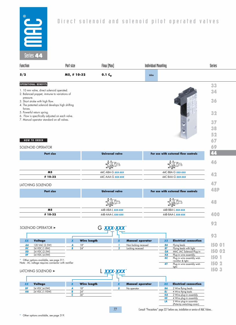
Port size
M5
# 10-32
Universal valve
44B-ABA-L XXX-XXX
44B-AAA-L XXX-XXX
For use with external flow controls
44B-BBA-L XXX-XXX
44B-BAA-L XXX-XXX
EB
B A
INEAEB
B A
INEA
LATCHING SOLENOID
OPERATIONAL BENEFITS
D i r e c t s o l e n o i d a n d s o l e n o i d p i l o t o p e r a t e d v a l v e s
H O W T O O R D E R
77 Consult “Precautions” page 327 before use, installation or service of MAC Valves..
36
32
3738
3334
5267
46
44
47
42
400
48
92
93
ISO 1ISO 2 ISO 3
69
48P
ISO 01ISO 02
Series 44
Function Port size Flow (Max) Individual Mounting Series
5/2 M5, # 10-32 0.1 Cv Inline
1. 10 mm valve, direct solenoid operated. 2. Balanced poppet, immune to variations of
pressure.3. Short stroke with high flow.4. The patented solenoid develops high shifting
forces.5. Powerful return spring.6. Flow is specifically adjusted on each valve.7. Manual operator standard on all valves.
Port size
M5
# 10-32
Universal valve
44C-ABA-G XXX-XXX
44C-AAA-G XXX-XXX
For use with external flow controls
44C-BBA-G XXX-XXX
44C-BAA-G XXX-XXX
EB
B A
INEAEB
B A
INEA
G XXX-XXX *SOLENOID OPERATOR �
Voltage
AA 120 VAC (2.5W)DC 24 VDC (1.8W)DD 24 VDC (2.5W)DF 24 VDC (4.0W)
Wire length
A 18”B 24”
Manual operator
1 Non-locking recessed2 Locking recessed
Electrical connection
BA Flying leadsBT Flying leads with lightGA MAC JAC Solenoid Plug-inKA Plug-in wire assembly.KC Plug-in wire assembly with
rectifier & lightKT Plug-in wire assembly with
light
XX X X XX
* Other options available, see page 311.Note : AC voltage requires connector with rectifier
L XXX-XXX *LATCHING SOLENOID �
Voltage
DF 24 VDC (4.0W)HA 24 VDC (1.95W)
Wire length
A 18”B 24”C 36”
Manual operator
0 No operator
Electrical connection
BA 2 Wire flying leadsBJ 4 Wire flying leadsKA 2 Wire plug-in assemblyKE 4 Wire plug-in assemblyLA 3 Wire plug-in assembly
(Polarity switching cover)
XX X X XX
* Other options available, see page 319.
SOLENOID OPERATOR

5,0
10,0
20,0
13,0
10,0
5,0
5,7
15,025,0
5,0
3,5
31,5
10,0
59,9
20,0
15,0
29,7
CL
CL
CLBEB
INEAA
1818100%100%
100%100% M O N T H S
WARRANTY
O FP R O D U C T I O N
T E S T E D
D I M E N S I O N S
T E C H N I C A L D A T A
Dimensions shown are metric (mm)
78 Consult “Precautions” page 327 before use, installation or service of MAC Valves..
Ø 3.3 MTG. HOLES
Series 44
Fluid :
Pressure range :
Lubrication :
Filtration :
Temperature range :
Flow :
Coil :
Voltage range :
Power :
Response times :
(with 4 W coil)
Compressed air, vacuum, inert gases
Vacuum to 120 PSI
Not required, if used select a medium aniline point lubricant (between 180°F and 210°F)
40 µ
0°F to 120°F (-18°C to +50°C)
4 W : (0.10 Cv) – 2.5 W : (0.08 Cv) – 1.8 W : (0.06 Cv) – 1.0W : (0.05 Cv)
Class A wire (#22 AWG x 18), continuous duty
-15% to +10% of nominal voltage
4 W – 2.5 W – 1.8 W – 1.0 W
Energize : 3.4 ms
De-energize : 1.5 ms
• Valve and coil are not interchangeable.Note :

79 Consult “Precautions” page 327 before use, installation or service of MAC Valves..
Individual mounting Series
D i r e c t s o l e n o i d a n d s o l e n o i d p i l o t o p e r a t e d v a l v e s
SERIES FEATURES
36
32
3738
3334
5267
46
44
47
42
400
48
92
93
ISO 1ISO 2 ISO 3
69
48P
ISO 01ISO 02
Inline
Manifold base“plug-in”
Manifold base“plug-in” with
pressureregulators
Manifold base“plug-in” withflow controls
Manifold base“plug-in”
with PR & FCStacking
Series 46
Manifold mounting
• Patented high force MACSOLENOID® for fastest possible response times.• Bonded balanced poppet for high flow, precise repeatability, and consistent operation.• Balanced poppet permits versatility in function — may be used as 3-way or 2-way normally open or
normally closed and may be used for vacuum, divertor, or selector applications.• Extremely high cycle rate capability.• Use on lube or non-lube service.• Manual overrides as standard.• Various solenoid enclosures and plug-in connectors.• Optional surge suppression available.• Low wattage DC solenoids — down to 1.3 watts.• Rectified AC voltage.
Exh. A
BIn
Push pin
Oval shaped armature
Encapsulated coil
Bonded balanced poppet
Return spring

OPERATIONAL BENEFITS
D i r e c t s o l e n o i d a n d s o l e n o i d p i l o t o p e r a t e d v a l v e s
H O W T O O R D E R
81 Consult “Precautions” page 327 before use, installation or service of MAC Valves..
36
32
3738
3334
5267
46
44
47
42
400
48
92
93
ISO 1ISO 2 ISO 3
69
48P
ISO 01ISO 02
Series 46
Function Port size Flow (Max) Individual mounting Series
4/2 1/8” - # 10-32 0.3 Cv Inline
1. Balanced poppet, immune to variations ofpressure.
2. Patented solenoid develops high shiftingforces.
3. Short stroke with high flow.4. Higher forces result in lower wattages for
given flow.5. Powerful return spring.
J XXX-XXX * (-G) Add “G” for ground SOLENOID OPERATOR �
Voltage
Single & double solenoidAA 120 VAC (5.4W)DA 24 VDC (5.4W)DB 12 VDC (5.4W)Single solenoid onlyDC 24 VDC (2.4W)DD 12 VDC (2.4W)
Wire length
O No leadsA 18”B 24”C 36”
Manual operator
1 Non-locking recessed2 Locking recessed
Electrical connection
BA Flying leadsGA MAC JAC solenoid plug-inGG MAC JAC solenoid plug-in
with rectifierJB Rectangular connectorJD Rectangular connector with
lightKA Mini square connectorKD Mini square connector with
light
XX X X XX
* Other options available, see page 317.** Use with rectangular and mini connectorsNote : - AC voltage requires connector with rectifier.
- With the MAC JAC, washdown capability is possible. Consult factory for washdown modification number.Double solenoid requires minimum 5.4 watts.
Examples : 46A-DG1-Jxxx-xxx (Bottom O ring mount – all ports)46A-CB1-Jxxx-xxx (4 port body with bottom ports – no side ports)
O P T I O N S
46A-AA1-JXXX-XXX
A Single operator - 4 port body with side portsC Single operator - 4 port body with bottom ports (No side ports – M5 or #10-32 ONLY)D Single operator - Bottom O ring mount – All ports (No side ports)F Single operator - Bottom O ring mount – Cylinder ports only – Side inlet & exhaustG Double operator - 4 Port body - With side portsH Double operator - Bottom O ring mount - All ports (No side ports)
G Use with O ring mount (body option ‘D’ & ‘H’)
Port size
1/8” NPTF
# 10-32
Without flow controls
46A-AA1-J XXX-XXX
46A-AB1-J XXX-XXX
With flow controls
46A-AA2-J XXX-XXX
46A-AB2-J XXX-XXX
Without flow controls
46A-GA1-J XXX-XXX
46A-GB1-J XXX-XXX
With flow controls
46A-GA2-J XXX-XXX
46A-GB2-J XXX-XXX
A BA B
EXH IN
A BA B
EXH IN
A BA B
EXH IN
A BA B
EXH IN
Single Operator Double Operator
**

16.3
8.5
IN
EX
32.5
70.9
3.2 DIA.
22.5
26.5
8.0
11.4
15.7
3.8 25.8
3.0
7.5
11.8
15.2
43.3
1/8" PORTS
25.8
3.8
10.9
109.4
43.3
3.0
15.7
8.0
EX
IN
8.0
15.2
11.0
32.7
7.5
26.5
38.0
18.8
Ø 3.4TYP. (2)
CONTROLSw/FLOW
22.5
CONTROLSw/o FLOW
Double solenoidSingle solenoid
1818100%100%
100%100% M O N T H S
WARRANTY
O FP R O D U C T I O N
T E S T E D
D I M E N S I O N S
T E C H N I C A L D A T A
Dimensions shown are metric (mm)
82 Consult “Precautions” page 327 before use, installation or service of MAC Valves..
Series 46
Fluid :
Pressure range :
Lubrication :
Filtration :
Temperature range :
Orifice :
Flow :
Coil :
Voltage range :
Protection :
Power :
Compressed air, vacuum, inert gases
Vacuum to 120 PSI
Not required, if used select a medium aniline point lubricant (between 180°F and 210°F)
40 µ
0°F to 120°F (-18°C to +50°C)
3,3 mm
1.8W : (0.20 Cv) – 2.4W : (0.20 Cv) – 5.4W : (0.30 Cv)
Class A wire (#22 AWG x 18), continuous duty
-15% to +10% of nominal voltage
Consult factory
5.4W – 2.4W – 1.8W
• BSPP threadsOptions :

OPERATIONAL BENEFITS
D i r e c t s o l e n o i d a n d s o l e n o i d p i l o t o p e r a t e d v a l v e s
H O W T O O R D E R
83 Consult “Precautions” page 327 before use, installation or service of MAC Valves..
36
32
3738
3334
5267
46
44
47
42
400
48
92
93
ISO 1ISO 2 ISO 3
69
48P
ISO 01ISO 02
Series 46
Function Port size Flow (Max) Manifold Mounting Series
4/2 1/8” - # 10-32 0.3 Cv Stacking
1. Balanced poppet, immune to variations ofpressure.
2. Patented solenoid develops high shiftingforces.
3. Short stroke with high flow.4. Higher forces result in lower wattages for
given flow.5. Powerful return spring.
Port size
1/8” NPTF
# 10-32
Without flow controls
46A-SA1-J XXX-XXX
46A-SB1-J XXX-XXX
With flow controls
46A-SA2-J XXX-XXX
46A-SB2-J XXX-XXX
A BA B
EXH IN
A BA B
EXH IN
J XXX-XXX * (-G) Add “G” for ground SOLENOID OPERATOR �
Voltage
AA 120 VAC (5.4W)DA 24 VDC (5.4W)DB 12 VDC (5.4W)DC 24 VDC (2.4W)DD 12 VDC (2.4W)
Wire length
A 18”B 24”C 36”
Manual operator
1 Non-locking recessed2 Locking recessed
Electrical connection
BA Flying leadsGA MAC JAC solenoid plug-inGB MAC JAC solenoid plug-in
with diodeGG MAC JAC solenoid plug-in
with rectifier
XX X X XX
* Other options available, see page 317.Note : - AC voltage requires connector with rectifier.
- With the MAC JAC, washdown capability is possible. Consult factory for washdown modification number.
End plate kit required (port size 1/4") : M-46001-01.

-
TYP.TYP.
TYP.
TYP.
TYP.
TYP.
19.810.5
32.610.1
15.0
27.4
12.7
7.0
Ø 5.3
21.1
152.04.9
Ø 5.3
33.6
152.05.0
CONTROLSWITHOUT FLOW
CONTROLSWITH FLOW
PORTS1/8" CYLINDER
EXHAUST COMMONS1/4" INLET AND
44.1 16.5
162.0
71.5
1818100%100%
100%100% M O N T H S
WARRANTY
O FP R O D U C T I O N
T E S T E D
D I M E N S I O N S
T E C H N I C A L D A T A
Dimensions shown are metric (mm)
84 Consult “Precautions” page 327 before use, installation or service of MAC Valves..
Series 46
Fluid :
Pressure range :
Lubrication :
Filtration :
Temperature range :
Flow :
Coil :
Voltage range :
Protection :
Power :
Response times :
(with 5.4 W coil)
Compressed air, vacuum, inert gases
Vacuum to 120 PSI
Not required, if used select a medium aniline point lubricant (between 180°F and 210°F)
40 µ
0°F to 120°F (-18°C to +50°C)
1.8W : (0.20 Cv) – 2.4W : (0.20 Cv) – 5.4W : (0.30 Cv)
Class A wire (#22 AWG x 18), continuous duty
-15% to +10% of nominal voltage
Consult factory
5.4W – 2.4W – 1.8W
Energize : 7.20 ms
De-energize : 4.20ms
• BSPP threads
• Inlet isolator : 28494 • Exhaust isolator : 28493 • Tie rod (x2) : 79411
Options :
Spare parts :

OPERATIONAL BENEFITS
D i r e c t s o l e n o i d a n d s o l e n o i d p i l o t o p e r a t e d v a l v e s
H O W T O O R D E R
85
36
32
3738
3334
5267
46
44
47
42
400
48
92
93
ISO 1ISO 2 ISO 3
69
48P
ISO 01ISO 02
Consult “Precautions” page 327 before use, installation or service of MAC Valves..
46
Series 46
Function Port size Flow (Max) Manifold mounting Series
4/2 1/8" - 5/32 O.D. Pressed-in 0.3 Cvtube receptacles
Manifold base“plug-in”
1. Balanced poppet, immune to variations ofpressure.
2. Patented solenoid develops high shiftingforces.
3. Short stroke with high flow.4. Higher forces result in lower wattages for
given flow.5. Powerful return spring.
Port size
Valve less base
1/8” NPTF
5/32 O.D. Pressed-in tube receptacles
Single solenoid
46A-L00-00-J XXP-XXX
46A-LSA-AC-J XXP-XXX
46A-LSF-AC-J XXP-XXX
Double solenoid
46A-N00-00-J XXP-XXX
46A-NSA-BL-J XXP-XXX
46A-NSF-BL-J XXP-XXX
A BA B
EXH IN
* Other options available, see page 317.Note : AC voltage requires connector with rectifier. Double solenoid requires minimum 5.4 watts.
Example : base only : 46A-0SA-AC.End plate kit required (port size 1/4") : M-46003-01.
O P T I O N S
46A-LSB-AC-JXXP-XXX
0 Base only - no valveL Single solenoid - Base mount bodyM Single solenoid - Base mount body with gage portN Double solenoid - Base mount bodyP Double solenoid - Base mount body with gage port
C Single solenoid - Side cylinder portsL Single & double solenoid - Bottom cylinder ports
Voltage
Single & double solenoidAA 120 VAC (5,4W)AC 24 VAC (5,4W)DA 24 VDC (5,4W)DB 12 VDC (5,4W)Single solenoid onlyDC 24 VDC (2,4W)DD 12 VDC (2,4W)
Manual operator
1 Non-locking2 Locking
Electrical connection
FA Base plug-inFB Base plug-in with diodeFG Base plug-in with rectifier
J XX P-XXX * (-G) Add “G” for ground SOLENOID OPERATOR �
XX X XX
A BA B
EXH IN

18.6 16.5 8.0
8.0
24.0
78.0
4.4
94.3
4.0
52.5
19.0
34.2
79.0
95.5
9.522.5
32.8Ø 4.3
TYP. TYP.
TYP.
3/4"-14 NPSM
95.5
8.5
62.915.0
35.5
104.1
95.5
8.5
62.915.0
35.5
104.1
1/4" COMMONS
78.0
4.4
4.0
52.5
19.0
34.2
79.0
95.5
9.5
22.5
32.8
Ø 4.3
TYP.
Double solenoid
1818100%100%
100%100% M O N T H S
WARRANTY
O FP R O D U C T I O N
T E S T E D
D I M E N S I O N S
T E C H N I C A L D A T A
Dimensions shown are metric (mm)
86 Consult “Precautions” page 327 before use, installation or service of MAC Valves..
Series 46
Fluid :
Pressure range :
Lubrication :
Filtration :
Temperature range :
Orific e
Flow :
Coil :
Voltage range :
Protection :
Power :
Response times :
Compressed air, vacuum, inert gases
Vacuum to 120 PSI
Not required, if used select a medium aniline point lubricant (between 180°F and 210°F)
40 µ
0°F to 120°F (-18°C to +50°C)
3.3 mm
1.8W : (0.20 Cv) – 2.4W : (0.20 Cv) – 5.4W : (0.30 Cv)
Epoxy encapsulated – Class A wires – 100% ED
-15% to +10% of nominal voltage
IP54 (electrical connection)
5.4W – 2.4W – 1.8W
Energize : 7.20 ms
De-energize : 4.20ms
• BSPP threads
• Inlet isolator : 28501 • Exhaust isolator : 28502 • Valve cover plate : M-46002 • Tie rod (x2) : 79443
Options :
Spare parts :

OPERATIONAL BENEFITS
D i r e c t s o l e n o i d a n d s o l e n o i d p i l o t o p e r a t e d v a l v e s
H O W T O O R D E R
87 Consult “Precautions” page 327 before use, installation or service of MAC Valves..
36
32
3738
3334
5267
46
44
47
42
400
48
92
93
ISO 1ISO 2 ISO 3
69
48P
ISO 01ISO 02
Series 46
Function Port size Flow (Max) Manifold mounting Series
4/2 1/8" - 5/32 O.D. Pressed-in 0.3 Cvtube receptacles
Manifold base“plug-in” with
pressureregulators
1. Balanced poppet, immune to variations ofpressure.
2. Patented solenoid develops high shiftingforces.
3. Short stroke with high flow.4. Higher forces result in lower wattages for
given flow.5. Powerful return spring.
Port size(Bottom ports only)
Valve less base
1/8” NPTF
5/32 O.D. Pressed-in tube receptacles
Model number
46A-L00-00-J XXP-XXX
46A-LSA-AJ-J XXP-XXX
46A-LSF-AJ-J XXP-XXX
A BA B
EXH IN
* Other options available, see page 317.Note : AC voltage requires connector with rectifier.
Example : base only with regulator : 46A-0SA-AJ.End plate kit required (port size 1/4") : M-46003-01.
O P T I O N S
46A-LSA-AJ-JXXP-XXX
0 Base only – no valveL Base mount bodyM Base mount body with gage port
J Regulator with adjusting knobE Regulator with slotted stemG Regulator with slotted stem with locknut
Voltage
AA 120 VAC (5.4W)DA 24 VDC (5.4W)DB 12 VDC (5.4W)DC 24 VDC (2.4W)
Manual operator
1 Non-locking recessed2 Locking recessed
Electrical connection
FA Base plug-inFB Base plug-in with diodeFG Base plug-in with rectifier
J XX P-XXX * (-G) Add “G” for ground SOLENOID OPERATOR �
XX X XX

78.0
4.494.3
Ø 4.3
4.0
52.5
18.6 16.5
32.8
22.5
9.5
34.2
19.0
79.0
95.5
69.2
95.5
8.5
TYP.
TYP.
PORT1/8" GAGE
3/4"-14 NPSM
1/4" COMMONS
62.9
15.0
35.5
104.1
1818100%100%
100%100% M O N T H S
WARRANTY
O FP R O D U C T I O N
T E S T E D
D I M E N S I O N S
T E C H N I C A L D A T A
Dimensions shown are metric (mm)
88 Consult “Precautions” page 327 before use, installation or service of MAC Valves..
Series 46
Fluid :
Pressure range :
Lubrication :
Filtration :
Temperature range :
Flow :
Coil :
Voltage range :
Protection :
Power :
Response times :
(with 5.4 W coil)
Compressed air, vacuum, inert gases
Vacuum to 120 PSI
Not required, if used select a medium aniline point lubricant (between 180°F and 210°F)
40 µ
0°F to 120°F (-18°C to +50°C)
1.8W : (0.20 Cv) – 2.4W : (0.20 Cv) – 5.4W : (0.30 Cv)
Class A continuous duty, #22 AWG x 12 base leads
-15% to +10% of nominal voltage
Consult factory
5.4W – 2.4W – 1.8W
Energize : 7.20 ms
De-energize : 4.20ms
• BSPP threads• Inlet isolator : 28501 • Exhaust isolator : 28502 • Valve cover plate : M-46002 • Tie rod (x2) : 79443• Replacement regulators : PR46A-0AAA (slotted stem)
PR46A-0BAA (adjusting knob)PR46A-0CAA (slotted stem with locknut)
• PR46A-xxxAA 0 to 120 PSIB 0 to 80 PSIC 0 to 30 PSI
Options :Spare parts :
Regulating range options :

OPERATIONAL BENEFITS
D i r e c t s o l e n o i d a n d s o l e n o i d p i l o t o p e r a t e d v a l v e s
H O W T O O R D E R
89 Consult “Precautions” page 327 before use, installation or service of MAC Valves..
36
32
3738
3334
5267
46
44
47
42
400
48
92
93
ISO 1ISO 2 ISO 3
69
48P
ISO 01ISO 02
Series 46
Function Port size Flow (Max) Manifold mounting Series
4/2 1/8" - 5/32 O.D. Pressed-in 0.3 Cvtube receptacles
Manifold base“plug-in” withflow controls
1. Balanced poppet, immune to variations ofpressure.
2. Patented solenoid develops high shiftingforces.
3. Short stroke with high flow.4. Higher forces result in lower wattages for
given flow.5. Powerful return spring.
Port size
Valve less base
1/8” NPTF
5/32 O.D. Pressed-in tube receptacles
Model number
46A-L00-00-J XXP-XXX
46A-LSA-AD-J XXP-XXX
46A-LSF-AD-J XXP-XXX
A BA B
EXH IN
* Other options available, see page 317.Note : AC voltage requires connector with rectifier.
Example : base only with flow controls: 46A-0SA-AD.End plate kit required (port size 1/4") : M-46003-01.
O P T I O N S
46A-LSA-AD-JXXP-XXX
0 Base only – no valveL Base mount bodyM Base mount body with gage port
D Side cylinder portsM Bottom cylinder ports
Voltage
AA 120 VAC (5.4W)DA 24 VDC (5.4W)DB 12 VDC (5.4W)DC 24 VDC (2.4W)
Manual operator
1 Non-locking recessed2 Locking recessed
Electrical connection
FA Base plug-inFB Base plug-in with diodeFG Base plug-in with rectifier
J XX P-XXX * (-G) Add “G” for ground SOLENOID OPERATOR �
XX X XX

78.0
4.4
94.3
Ø 4.3
4.0
52.5
18.6 16.5
32.8
22.59.5
34.2
19.0
79.0
95.5
8.0
8.0
24.0
TYP.
TYP.TYP.
3/4"-14 NPSM
1/4" COMMONS
95.5
8.5
62.9
15.0
35.5
104.1
1818100%100%
100%100% M O N T H S
WARRANTY
O FP R O D U C T I O N
T E S T E D
D I M E N S I O N S
T E C H N I C A L D A T A
Dimensions shown are metric (mm)
90 Consult “Precautions” page 327 before use, installation or service of MAC Valves..
Series 46
Fluid :
Pressure range :
Lubrication :
Filtration :
Temperature range :
Flow :
Coil :
Voltage range :
Protection :
Power :
Response times :
Compressed air, vacuum, inert gases
Vacuum to 120 PSI
Not required, if used select a medium aniline point lubricant (between 180°F and 210°F)
40 µ
0°F to 120°F (-18°C to +50°C)
1.8W : (0.20 Cv) – 2.4W : (0.20 Cv) – 5.4W : (0.30 Cv)
Class A continuous duty, #22 AWG x 12 base leads
-15% to +10% of nominal voltage
Consult factory
5.4W – 2.4W – 1.8W
Energize : 7.20 ms
De-energize : 4.20ms
• BSPP threads
• Inlet isolator : 28501 • Exhaust isolator : 28502 • Valve cover plate : M-46002 • Tie rod (x2) : 79443
Options :
Spare parts :
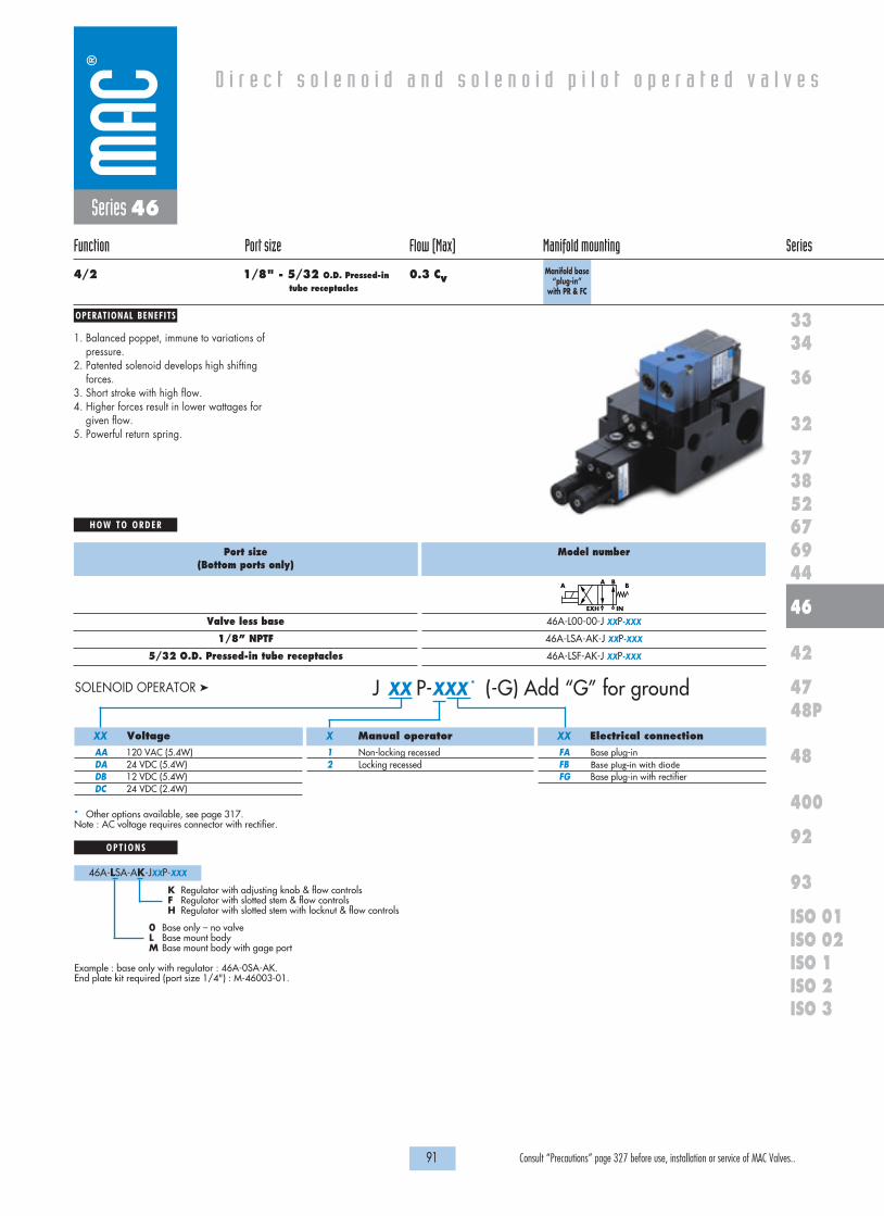
OPERATIONAL BENEFITS
D i r e c t s o l e n o i d a n d s o l e n o i d p i l o t o p e r a t e d v a l v e s
H O W T O O R D E R
91 Consult “Precautions” page 327 before use, installation or service of MAC Valves..
36
32
3738
3334
5267
46
44
47
42
400
48
92
93
ISO 1ISO 2 ISO 3
69
48P
ISO 01ISO 02
Series 46
Function Port size Flow (Max) Manifold mounting Series
4/2 1/8" - 5/32 O.D. Pressed-in 0.3 Cvtube receptacles
Manifold base “plug-in”
with PR & FC
1. Balanced poppet, immune to variations ofpressure.
2. Patented solenoid develops high shiftingforces.
3. Short stroke with high flow.4. Higher forces result in lower wattages for
given flow.5. Powerful return spring.
Port size(Bottom ports only)
Valve less base
1/8” NPTF
5/32 O.D. Pressed-in tube receptacles
Model number
46A-L00-00-J XXP-XXX
46A-LSA-AK-J XXP-XXX
46A-LSF-AK-J XXP-XXX
A BA B
EXH IN
* Other options available, see page 317.Note : AC voltage requires connector with rectifier.
Example : base only with regulator : 46A-0SA-AK.End plate kit required (port size 1/4") : M-46003-01.
O P T I O N S
46A-LSA-AK-JXXP-XXX
0 Base only – no valveL Base mount bodyM Base mount body with gage port
K Regulator with adjusting knob & flow controlsF Regulator with slotted stem & flow controlsH Regulator with slotted stem with locknut & flow controls
Voltage
AA 120 VAC (5.4W)DA 24 VDC (5.4W)DB 12 VDC (5.4W)DC 24 VDC (2.4W)
Manual operator
1 Non-locking recessed2 Locking recessed
Electrical connection
FA Base plug-inFB Base plug-in with diodeFG Base plug-in with rectifier
J XX P-XXX * (-G) Add “G” for ground SOLENOID OPERATOR �
XX X XX

78.0
4.494.3
Ø 4.3
4.0
52.5
18.6 16.5
32.8
22.5
9.5
34.2
19.0
79.0
95.5
69.2
TYP.
TYP.
PORT1/8" GAGE
3/4"-14 NPSM
1/4" COMMONS
95.5
8.5
62.9
15.0
35.5
104.1
1818100%100%
100%100% M O N T H S
WARRANTY
O FP R O D U C T I O N
T E S T E D
D I M E N S I O N S
T E C H N I C A L D A T A
Dimensions shown are metric (mm)
92 Consult “Precautions” page 327 before use, installation or service of MAC Valves..
Series 46
Fluid :
Pressure range :
Lubrication :
Filtration :
Temperature range :
Flow :
Coil :
Voltage range :
Protection :
Power :
Response times :
Compressed air, vacuum, inert gases
Vacuum to 120 PSI
Not required, if used select a medium aniline point lubricant (between 180°F and 210°F)
40 µ
0°F to 120°F (-18°C to +50°C)
1.8W : (0.20 Cv) – 2.4W : (0.20 Cv) – 5.4W : (0.30 Cv)
Class A continuous duty, #22 AWG x 12 base leads
-15% to +10% of nominal voltage
Consult factory
5.4W – 2.4W – 1.8W
Energize : 7.20 ms
De-energize : 4.20ms
• BSPP threads• Inlet isolator : 28501 • Exhaust isolator : 28502 • Valve cover plate : M-46002 • Tie rod (x2) : 79443• Replacement regulators : PR46A-0AAA (slotted stem)
PR46A-0BAA (adjusting knob)PR46A-0CAA (slotted stem with locknut)
• PR46A-xxxAA 0 to 120 PSIB 0 to 80 PSIC 0 to 30 PSI
Options :Spare parts :
Regulating range options :

93 Consult “Precautions” page 327 before use, installation or service of MAC Valves..
Individual mounting Series
D i r e c t s o l e n o i d a n d s o l e n o i d p i l o t o p e r a t e d v a l v e s
SERIES FEATURES
36
32
3738
3334
5267
46
44
47
42
400
48
92
93
ISO 1ISO 2 ISO 3
69
48P
ISO 01ISO 02
Sub-basenon “plug-in”
Sub-base“plug-in”
Sub-base/manifold basenon “plug-in” with latching
solenoid
Sub-base/manifold base
“plug-in” with latching
solenoid
Manifold base“plug-in”
Sub-base/manifold basenon “plug-in” with latching
solenoid
Sub-base/manifold base
“plug-in” with latching
solenoid
Manifold basenon “plug-in”
Series 42
Manifold mounting
• High force MACSOLENOID®.• Integral 4-way pilot design.• Single or dual pressure.• Internal or external pilot.• Single or double solenoid.• 2 or 3 position.• Rectified AC voltage.• Latching solenoid technology.
3 2 1 4 5
Manual operator
Integral 4-way pilot
Solenoid
Air returnBonded spool

OPERATIONAL BENEFITS
D i r e c t s o l e n o i d a n d s o l e n o i d p i l o t o p e r a t e d v a l v e s
H O W T O O R D E R
95 Consult “Precautions” page 327 before use, installation or service of MAC Valves..
36
32
3738
3334
5267
46
44
47
42
400
48
92
93
ISO 1ISO 2 ISO 3
69
48P
ISO 01ISO 02
5/2 Single solenoid
42B-AMA-000-GXXX-XXX
42B-AMD-000-GXXX-XXX
42B-AMA-AAL-GXXX-XXX
42B-AMD-AAM-GXXX-XXX
42B-AMA-EAL-GXXX-XXX
42B-AMD-EAM-GXXX-XXX
5/2 Double solenoid
42B-BMA-000-GXXX-XXX
42B-BMD-000-GXXX-XXX
42B-BMA-AAL-GXXX-XXX
42B-BMD-AAM-GXXX-XXX
42B-BMA-EAL-GXXX-XXX
42B-BMD-EAM-GXXX-XXX
5/3 Closed center
42B-EMA-000-GXXX-XXX
42B-EMD-000-GXXX-XXX
42B-EMA-AAL-GXXX-XXX
42B-EMD-AAM-GXXX-XXX
42B-EMA-EAL-GXXX-XXX
42B-EMD-EAM-GXXX-XXX
5/3 Open center
42B-FMA-000-GXXX-XXX
42B-FMD-000-GXXX-XXX
42B-FMA-AAL-GXXX-XXX
42B-FMD-AAM-GXXX-XXX
42B-FMA-EAL-GXXX-XXX
42B-FMD-EAM-GXXX-XXX
2 412 14
3 1 5
2 412 14
3 1 5
2 412 14
3 1 5
2 412 14
3 1 5
Port size
Valve less
base
# 10-32
1/4” O.D.
tube receptacles
Pilot air
Internal
External
Internal
External
Internal
External
Series 42
Function Port size Flow (Max) Individual mounting Series
5/2, 5/3 # 10-32 - 0.4 Cv1/4” O.D. tube receptacle
Sub-base non“plug-in”
1. 4-way valve with 4-way integral pilot.2. 10 mm valve (stacks on 10.5 mm centers).3. High flow (up to 0.4 Cv).4. Fast repeatable response times.5. Maximum shifting forces in both directions.6. Long life.
SINGLE PRESSURE MODELS (VALVE WITH BASE CODED FOR SIDE PORTS)
5/2 Single solenoid
42B-CMB-000-GXXX-XXX
42B-CMC-000-GXXX-XXX
42B-CMD-000-GXXX-XXX
42B-CMB-AAL-GXXX-XXX
42B-CMC-AAL-GXXX-XXX
42B-CMD-AAM-GXXX-XXX
42B-CMB-EAL-GXXX-XXX
42B-CMC-EAL-GXXX-XXX
42B-CMD-EAM-GXXX-XXX
5/2 Double solenoid
42B-DMB-000-GXXX-XXX
42B-DMC-000-GXXX-XXX
42B-DMD-000-GXXX-XXX
42B-DMB-AAL-GXXX-XXX
42B-DMC-AAL-GXXX-XXX
42B-DMD-AAM-GXXX-XXX
42B-DMB-EAL-GXXX-XXX
42B-DMC-EAL-GXXX-XXX
42B-DMD-EAM-GXXX-XXX
5/3 Pressure center
42B-HMB-000-GXXX-XXX
42B-HMC-000-GXXX-XXX
42B-HMD-000-GXXX-XXX
42B-HMB-AAL-GXXX-XXX
42B-HMC-AAL-GXXX-XXX
42B-HMD-AAM-GXXX-XXX
42B-HMB-EAL-GXXX-XXX
42B-HMC-EAL-GXXX-XXX
42B-HMD-EAM-GXXX-XXX
Port size
Valve less base
# 10-32
1/4” O.D.
tube receptacles
Pilot air
Internal Supply #3 port
Supply #5 port
External
Internal Supply #3 port
Supply #5 port
External
Internal Supply #3 port
Supply #5 port
External
DUAL PRESSURE MODELS (VALVE WITH BASE CODED FOR SIDE PORTS)
G XXX-XXX *STANDARD SOLENOID OPERATOR �
Voltage
AA 120 VAC (2.5W)DC 24 VDC (1.8W)DD 24 VDC (2.5W)DF 24 VDC (4.0W)
Wire length
A 18”B 24”C 36”
Manual operator
1 Non-locking recessed2 Locking recessed
Electrical connection
BA Flying leadsBT Flying leads with lightGA MAC JAC solenoid Plug-inKA Plug-in wire assy.KT Plug-in wire assy. with lightKD Plug-in wire assy. with
rectifier & light & ground
XX X X XX
Note : AC voltage requires connector with rectifier.* Other options available, see page 311.Latching solenoid available for 5/2 valves.Other options available for the 42 series valves, see page 107.
24 1214
31
5
24 1214
31
5
2 412 14
3 1 5

1818100%100%
100%100% M O N T H S
WARRANTY
O FP R O D U C T I O N
T E S T E D
D I M E N S I O N S
T E C H N I C A L D A T A
Dimensions shown are metric (mm)
96 Consult “Precautions” page 327 before use, installation or service of MAC Valves..
3
1
5
12
4
2
MO
DEL
AU
CKL
AN
D, N
.Z.
LIEG
E, B
ELG
IUM
WIX
OM
, MI.
USA
MO
DIF
.
18.5
5.5
22.4
76.5
TYP.
TYP.
4.3
4.8
99.1
TYP.
TYP.
(SHOWN WITH M7 PORTS)
9.523.7
4.8
35.0
Ø 5.3
DOUBLE21.1
Series 42
Fluid :
Pressure range :
Pilot pressure :
Lubrication :
Filtration :
Temperature range :
Flow :
Coil :
Voltage range :
Power :
Response times :
(with 24V 4 W coil)
Compressed air, vacuum, inert gases
Internal Pilot - 2 pos. : 20 to 120 PSI 3 pos. : 40 to 120 PSI
External Pilot : vacuum to 120 PSI
2 position : 20 to 120 PSI 3 position : 40 to 120 PSI
Not required, if used select a medium aniline point lubricant (between 180°F and 210°F)
40 µ
0°F to 120°F (-18°C to +50°C)
# 10-32 : (0.35 Cv) – 1/4” O.D. tube receptacle : (0.4 Cv)
Class A wire (#22 AWG x 18), continuous duty
-15% to +10% of nominal voltage
1.0 to 4.0 W
Energize : 5 ms
De-energize : 5 ms
• M5 ports, M7 ports, 6 mm O.D. tube receptacles• Sandwich flow controls : FC42B-BB• Sandwich regulator : see ‘Regulator’ section
Options :

OPERATIONAL BENEFITS
D i r e c t s o l e n o i d a n d s o l e n o i d p i l o t o p e r a t e d v a l v e s
H O W T O O R D E R
97 Consult “Precautions” page 327 before use, installation or service of MAC Valves..
36
32
3738
3334
5267
46
44
47
42
400
48
92
93
ISO 1ISO 2 ISO 3
69
48P
ISO 01ISO 02
5/2Single solenoid
42B-CMB-000-GXXP-XXX
42B-CMC-000-GXXP-XXX
42B-CMD-000-GXXP-XXX
42B-CMB-AAA-GXXP-XXX
42B-CMC-AAA-GXXP-XXX
42B-CMD-AAB-GXXP-XXX
42B-CMB-EAA-GXXP-XXX
42B-CMC-EAA-GXXP-XXX
42B-CMD-EAB-GXXP-XXX
5/2Double solenoid
42B-DMF-000-GXXP-XST
42B-DMG-000-GXXP-XST
42B-DMH-000-GXXP-XST
42B-DMF-AAC-GXXP-XST
42B-DMG-AAC-GXXP-XST
42B-DMH-AAD-GXXP-XST
42B-DMF-EAC-GXXP-XST
42B-DMG-EAC-GXXP-XST
42B-DMH-EAD-GXXP-XST
5/3Pressure center
42B-HMF-000-GXXP-XST
42B-HMG-000-GXXP-XST
42B-HMH-000-GXXP-XST
42B-HMF-AAC-GXXP-XST
42B-HMG-AAC-GXXP-XST
42B-HMH-AAD-GXXP-XST
42B-HMF-EAC-GXXP-XST
42B-HMG-EAC-GXXP-XST
42B-HMH-EAD-GXXP-XST
Port size
Valve less base
# 10-32
1/4” O.D.
tube receptacles
Pilot air
Internal Supply #3 port
Supply #5 port
External
Internal Supply #3 port
Supply #5 port
External
Internal Supply #3 port
Supply #5 port
External
5/2Single solenoid
42B-AMA-000-GXXP-XXX
42B-AMD-000-GXXP-XXX
42B-AMA-AAA-GXXP-XXX
42B-AMD-AAB-GXXP-XXX
42B-AMA-EAA-GXXP-XXX
42B-AMD-EAB-GXXP-XXX
5/2Double solenoid
42B-BME-000-GXXP-XST
42B-BMH-000-GXXP-XST
42B-BME-AAC-GXXP-XST
42B-BMH-AAD-GXXP-XST
42B-BME-EAC-GXXP-XST
42B-BMH-EAD-GXXP-XST
5/3Closed center
42B-EME-000-GXXP-XST
42B-EMH-000-GXXP-XST
42B-EME-AAC-GXXP-XST
42B-EMH-AAD-GXXP-XST
42B-EME-EAC-GXXP-XST
42B-EMH-EAD-GXXP-XST
5/3Open center
42B-FME-000-GXXP-XST
42B-FMH-000-GXXP-XST
42B-FME-AAC-GXXP-XST
42B-FMH-AAD-GXXP-XST
42B-FME-EAC-GXXP-XST
42B-FMH-EAD-GXXP-XST
2 412 14
3 1 5
2 412 14
3 1 5
2 412 14
3 1 5
2 412 14
3 1 5
Port size
Valve less
base
# 10-32
1/4” O.D.
tube receptacles
Pilot air
Internal
External
Internal
External
Internal
External
Series 42
Function Port size Flow (Max) Individual mounting Series
5/2, 5/3 # 10-32 - 0.4 Cv1/4” O.D. tube receptacle
Sub-base“plug-in”
1. 4-way valve with 4-way integral pilot.2. 10 mm valve (stacks on 10.5 mm centers).3. High flow (up to 0.4 Cv).4. Fast repeatable response times.5. Maximum shifting forces in both directions.6. Long life.
SINGLE PRESSURE MODELS (LED STANDARD EXCEPT FOR SINGLE SOLENOIDS) - MODELS CODED FOR SIDE PORTS
DUAL PRESSURE MODELS (LED STANDARD EXCEPT FOR SINGLE SOLENOIDS) - MODELS CODED FOR SIDE PORTS
Voltage
AA 120 VAC (2.5W)DC 24 VDC (1.8W)DD 24 VDC (2.5W)DF 24 VDC (4.0W)
Manual operator
1 Non-locking recessed2 Locking recessed
Electrical connection
Double solenoid & 3 position modelsST Base plug-inSingle solenoid modelsSA Base plug-inSJ Base plug-in with lightSS Base plug-in with rectifier & light & ground
G XX P-XXX *STANDARD SOLENOID OPERATOR �
XX X XX
Note : AC voltage requires connector with rectifier (for double solenoid consult factory).* Other options available, see page 311.Other options available for the 42 series valves, see page 108.
24 1214
31
5
24 1214
31
5
2 412 14
3 1 5

CO
ND
5
13
EP
2
4
MO
DEL
AU
CKL
AN
D, N
.Z.
LIEG
E, B
ELG
IUM
WIX
OM
, MI.
USA
MO
DIF
.
20.0
6.0
9.5
11.116.923.0
26.0
23.2
40.1
56.5
67.5
94.4
6.0
11.0
4.0
TYP.
TYP.
TYP.
TYP.
TYP.
TYP.
66.5
Ø 4.3
(M7 PORTS SHOWN) 24.5TYP.
75.3
30.5
37.6
EXT. PILOT1/8" COMMON
COMMONS1/4" IN&EXH
1"-11 1/2 NPSM 46.0
23.2
75.0
1818100%100%
100%100% M O N T H S
WARRANTY
O FP R O D U C T I O N
T E S T E D
D I M E N S I O N S
T E C H N I C A L D A T A
Dimensions shown are metric (mm)
98 Consult “Precautions” page 327 before use, installation or service of MAC Valves..
Series 42
Fluid :
Pressure range :
Pilot pressure :
Lubrication :
Filtration :
Temperature range :
Flow :
Coil :
Voltage range :
Power :
Response times :
(with 24V 4 W coil)
Compressed air, vacuum, inert gases
Internal Pilot - 2 pos. : 20 to 120 PSI 3 pos. : 40 to 120 PSI
External Pilot : vacuum to 120 PSI
2 position : 20 to 120 PSI 3 position : 40 to 120 PSI
Not required, if used select a medium aniline point lubricant (between 180°F and 210°F)
40 µ
0°F to 120°F (-18°C to +50°C)
# 10-32 : (0.35 Cv) – 1/4” O.D. tube receptacle : (0.4 Cv)
Class A continuous duty, #22 AWG x 12 base leads
-15% to +10% of nominal voltage
1.0 to 4.0 W
Energize : 5 ms
De-energize : 5 ms
• M5 ports, M7 ports, 6 mm O.D. tube receptacles• Sandwich flow controls : FC42B-AB• Sandwich regulator : see ‘Regulator’ section
Options :

OPERATIONAL BENEFITS
D i r e c t s o l e n o i d a n d s o l e n o i d p i l o t o p e r a t e d v a l v e s
H O W T O O R D E R
99 Consult “Precautions” page 327 before use, installation or service of MAC Valves..
36
32
3738
3334
5267
46
44
47
42
400
48
92
93
ISO 1ISO 2 ISO 3
69
48P
ISO 01ISO 02
5/2 Single solenoid
42B-AMA-000-GXXX-XXX
42B-AMD-000-GXXX-XXX
42B-AMA-AJL-GXXX-XXX
42B-AMD-AJM-GXXX-XXX
42B-AMA-EJL-GXXX-XXX
42B-AMD-EJM-GXXX-XXX
5/2 Double solenoid
42B-BMA-000-GXXX-XXX
42B-BMD-000-GXXX-XXX
42B-BMA-AJL-GXXX-XXX
42B-BMD-AJM-GXXX-XXX
42B-BMA-EJL-GXXX-XXX
42B-BMD-EJM-GXXX-XXX
5/3 Closed center
42B-EMA-000-GXXX-XXX
42B-EMD-000-GXXX-XXX
42B-EMA-AJL-GXXX-XXX
42B-EMD-AJM-GXXX-XXX
42B-EMA-EJL-GXXX-XXX
42B-EMD-EJM-GXXX-XXX
5/3 Open center
42B-FMA-000-GXXX-XXX
42B-FMD-000-GXXX-XXX
42B-FMA-AJL-GXXX-XXX
42B-FMD-AJM-GXXX-XXX
42B-FMA-EJL-GXXX-XXX
42B-FMD-EJM-GXXX-XXX
2 412 14
3 1 5
2 412 14
3 1 5
2 412 14
3 1 5
2 412 14
3 1 5
Port size
Valve less
base
# 10-32
1/4” O.D.
tube receptacles
Pilot air
Internal
External
Internal
External
Internal
External
Series 42
Function Port size Flow (Max) Manifold mounting Series
5/2, 5/3 # 10-32 - 0.4 Cv1/4” O.D. tube receptacle
Manifold basenon “plug-in”
1. 4-way valve with 4-way integral pilot.2. 10 mm valve (stacks on 10.5 mm centers).3. High flow (up to 0.4 Cv).4. Fast repeatable response times.5. Maximum shifting forces in both directions.6. Long life.
SINGLE PRESSURE MODELS (MIDDLE STATION MANIFOLDS WITH SIDE PORTS)
5/2 Single solenoid
42B-CMB-000-GXXX-XXX
42B-CMC-000-GXXX-XXX
42B-CMD-000-GXXX-XXX
42B-CMB-AJL-GXXX-XXX
42B-CMC-AJL-GXXX-XXX
42B-CMD-AJM-GXXX-XXX
42B-CMB-EJL-GXXX-XXX
42B-CMC-EJL-GXXX-XXX
42B-CMD-EJM-GXXX-XXX
5/2 Double solenoid
42B-DMB-000-GXXX-XXX
42B-DMC-000-GXXX-XXX
42B-DMD-000-GXXX-XXX
42B-DMB-AJL-GXXX-XXX
42B-DMC-AJL-GXXX-XXX
42B-DMD-AJM-GXXX-XXX
42B-DMB-EJL-GXXX-XXX
42B-DMC-EJL-GXXX-XXX
42B-DMD-EJM-GXXX-XXX
5/3 Pressure center
42B-HMB-000-GXXX-XXX
42B-HMC-000-GXXX-XXX
42B-HMD-000-GXXX-XXX
42B-HMB-AJL-GXXX-XXX
42B-HMC-AJL-GXXX-XXX
42B-HMD-AJM-GXXX-XXX
42B-HMB-EJL-GXXX-XXX
42B-HMC-EJL-GXXX-XXX
42B-HMD-EJM-GXXX-XXX
Port size
Valve less base
# 10-32
1/4” O.D.
tube receptacles
Pilot air
Internal Supply #3 port
Supply #5 port
External
Internal Supply #3 port
Supply #5 port
External
Internal Supply #3 port
Supply #5 port
External
DUAL PRESSURE MODELS (MIDDLE STATION MANIFOLDS WITH SIDE PORTS)
G XXX-XXX *STANDARD SOLENOID OPERATOR �
Voltage
AA 120 VAC (2.5W)DC 24 VDC (1.8W)DD 24 VDC (2.5W)DF 24 VDC (4.0W)
Wire length
A 18”B 24”C 36”
Manual operator
1 Non-locking recessed2 Locking recessed
Electrical connection
BA Flying leadsBT Flying leads with lightGA MAC JAC solenoid plug-inKA Plug-in wire assy.KT Plug-in wire assy. with lightKD Plug-in wire assy. with
rectifier & light & ground
XX X X XX
Note : - AC voltage requires connector with rectifier.* Other options available, see page 311.Latching solenoid available for 5/2 valves.Manifold assemblies consist of (1) left end manifold, (1) right end manifold, andmiddle station manifolds (options "J" or "K").Other options available for the 42 series valves, see page 107.
2 412 14
3 1 5
24 1214
31
5
24 1214
31
5

1818100%100%
100%100% M O N T H S
WARRANTY
O FP R O D U C T I O N
T E S T E D
D I M E N S I O N S
T E C H N I C A L D A T A
Dimensions shown are metric (mm)
100 Consult “Precautions” page 327 before use, installation or service of MAC Valves..
3
1
5
12
2
4
12
2
4
3
1
5
12
4
2
MO
DEL
AU
CKL
AN
D, N
.Z.
LIEG
E, B
ELG
IUM
WIX
OM
, MI.
USA
MO
DIF
.
MO
DEL
AU
CKL
AN
D, N
.Z.
LIEG
E, B
ELG
IUM
WIX
OM
, MI.
USA
MO
DIF
.
MO
DEL
AU
CKL
AN
D, N
.Z.
LIEG
E, B
ELG
IUM
WIX
OM
, MI.
USA
MO
DIF
.
2
4
2
44
2
18.5
10.5
5.5
22.4 23.8
12.8
FLOW CONTROL SANDWICH
WITH OPTIONAL 95.1
76.5
TYP.
TYP.
TYP.
4.353.6
4.8
99.1
TYP.
TYP.
9.511.1
16.920.4
23.2
40.3
56.7
70.4
18.5 10.5
33.1
45.0
TYP. TYP.
TYP.
TYP.
Ø 5.3TYP.
6MM TUBE RECEPTACLES M7, AND SCREW IN 1/4" AND ARE AVAILABLE IN 10-32, M5,*SIDE AND BOTTOM PORTS
6MM TUBE RECEPTACLESFOR INTALLATION OF 1/4" AND4MM HEX WRECH REQUIRED
IN TUBE RECEPTACLEOPTIONAL SCREW
17.0
17.058.0
COMMONS1/4" IN & EXH
PILOT COMMON1/8" EXT.
(SHOWN WITH M7 PORTS)
120.3
Series 42
Fluid :
Pressure range :
Pilot pressure :
Lubrication :
Filtration :
Temperature range :
Flow :
Coil :
Voltage range :
Power :
Response times :
(with 24V 4 W coil)
Compressed air, vacuum, inert gases
Internal Pilot - 2 pos. : 20 to 120 PSI 3 pos. : 40 to 120 PSI
External Pilot : vacuum to 120 PSI
2 position : 20 to 120 PSI 3 position : 40 to 120 PSI
Not required, if used select a medium aniline point lubricant (between 180°F and 210°F)
40 µ
0°F to 120°F (-18°C to +50°C)
# 10-32 : (0.35 Cv) – 1/4” O.D. tube receptacle : (0.4 Cv)
Class A wire (#22 AWG x 18), continuous duty
-15% to +10% of nominal voltage
1.0 to 4.0 W
Energize : 5 ms
De-energize : 5 ms
• M5 ports, M7 ports, 6 mm O.D. tube receptacles • Sandwich flow controls : FC42B-BB • Sandwich regulator : see "regulators" section • Isolator disk for inlet or exhaust: 28454• Valve blanking plate : M-42004
Options :

OPERATIONAL BENEFITS
D i r e c t s o l e n o i d a n d s o l e n o i d p i l o t o p e r a t e d v a l v e s
H O W T O O R D E R
101 Consult “Precautions” page 327 before use, installation or service of MAC Valves..
36
32
3738
3334
5267
46
44
47
42
400
48
92
93
ISO 1ISO 2 ISO 3
69
48P
ISO 01ISO 02
5/2 Single solenoid
42B-AMA-000-GXXP-XXX
42B-AMD-000-GXXP-XXX
42B-AMA-AJA-GXXP-XXX
42B-AMD-AJB-GXXP-XXX
42B-AMA-EJA-GXXP-XXX
42B-AMD-EJB-GXXP-XXX
5/2 Double solenoid
42B-BME-000-GXXP-XST
42B-BMH-000-GXXP-XST
42B-BME-AJC-GXXP-XST
42B-BMH-AJD-GXXP-XST
42B-BME-EJC-GXXP-XST
42B-BMH-EJD-GXXP-XST
5/3 Closed center
42B-EME-000-GXXP-XST
42B-EMH-000-GXXP-XST
42B-EME-AJC-GXXP-XST
42B-EMH-AJD-GXXP-XST
42B-EME-EJC-GXXP-XST
42B-EMH-EJD-GXXP-XST
5/3 Open center
42B-FME-000-GXXP-XST
42B-FMH-000-GXXP-XST
42B-FME-AJC-GXXP-XST
42B-FMH-AJD-GXXP-XST
42B-FME-EJC-GXXP-XST
42B-FMH-EJD-GXXP-XST
2 412 14
3 1 5
2 412 14
3 1 5
2 412 14
3 1 5
2 412 14
3 1 5
Port size
Valve less
base
# 10-32
1/4” O.D.
tube receptacles
Pilot air
Internal
External
Internal
External
Internal
External
Series 42
Function Port size Flow (Max) Manifold mounting Series
5/2, 5/3 # 10-32 - 0.4 Cv1/4” O.D. tube receptacle
Manifold base“plug-in”
1. 4-way valve with 4-way integral pilot.2. 10 mm valve (stacks on 10.5 mm centers).3. High flow (up to 0.4 Cv).4. Fast repeatable response times.5. Maximum shifting forces in both directions.6. Long life.
SINGLE PRESSURE MODELS (LED STANDARD EXCEPT FOR SINGLE SOLENOIDS)
5/2 Single solenoid
42B-CMB-000-GXXP-XXX
42B-CMC-000-GXXP-XXX
42B-CMD-000-GXXP-XXX
42B-CMB-AJA-GXXP-XXX
42B-CMC-AJA-GXXP-XXX
42B-CMD-AJB-GXXP-XXX
42B-CMB-EJA-GXXP-XXX
42B-CMC-EJA-GXXP-XXX
42B-CMD-EJB-GXXP-XXX
5/2 Double solenoid
42B-DMF-000-GXXP-XST
42B-DMG-000-GXXP-XST
42B-DMH-000-GXXP-XST
42B-DMF-AJC-GXXP-XST
42B-DMG-AJC-GXXP-XST
42B-DMH-AJD-GXXP-XST
42B-DMF-EJC-GXXP-XST
42B-DMG-EJC-GXXP-XST
42B-DMH-EJD-GXXP-XST
5/3 Pressure center
42B-HMF-000-GXXP-XST
42B-HMG-000-GXXP-XST
42B-HMH-000-GXXP-XST
42B-HMF-AJC-GXXP-XST
42B-HMG-AJC-GXXP-XST
42B-HMH-AJD-GXXP-XST
42B-HMF-EJC-GXXP-XST
42B-HMG-EJC-GXXP-XST
42B-HMH-EJD-GXXP-XST
Port size
Valve less base
# 10-32
1/4” O.D.
tube receptacles
Pilot air
Internal Supply #3 port
Supply #5 port
External
Internal Supply #3 port
Supply #5 port
External
Internal Supply #3 port
Supply #5 port
External
DUAL PRESSURE MODELS (LED STANDARD EXCEPT FOR SINGLE SOLENOIDS)
Voltage
AA 120 VAC (2.5W)DC 24 VDC (1.8W)DD 24 VDC (2.5W)DF 24 VDC (4.0W)
Manual operator
1 Non-locking recessed2 Locking recessed
Electrical connection
Double solenoid & 3 position modelsST Base plug-inSingle solenoid modelsSA Base plug-inSJ Base plug-in with lightSS Base plug-in with rectifier & light & ground
G XX P-XXX *STANDARD SOLENOID OPERATOR �
XX X XX
* Other options available, see page 311.** Latching solenoid available for 5/2 valves.Note : - AC voltage requires connector with rectifier (for double solenoid consult factory).
- Manifold assemblies consist of (1) left end manifold, (1) right endmanifold, and middle station manifolds (options "J" or "K").
Other options available for the 42 series valves, see page 108.
Above numbers are middle station manifolds with side ports
2 412 14
3 1 5
24 1214
31
5
24 1214
31
5

12
MO
DIF
.
AU
CKL
AN
D, N
.Z.
LIEG
E, B
ELG
IUM
WIX
OM
, MI.
USA
MO
DEL
12
MO
DEL
12
MO
DEL
AU
CKL
AN
D, N
.Z.
LIEG
E, B
ELG
IUM
WIX
OM
, MI.
USA
MO
DIF
.
12
MO
DEL
AU
CKL
AN
D, N
.Z.
LIEG
E, B
ELG
IUM
WIX
OM
, MI.
USA
MO
DIF
.
4
2
4
2
X
53
1
X
53
1
2
4 4
2
18.5 10.5
33.1
45.0
TYP. TYP.
TYP.
TYP.
6MM TUBE RECEPTACLESFOR INTALLATION OF 1/4" AND4MM HEX WRECH REQUIRED
4
2
4
2
MO
DIF
.
AU
CKL
AN
D, N
.Z.
LIEG
E, B
ELG
IUM
WIX
OM
, MI.
USA
4
22
4
68.417.0
17.0
IN TUBE RECEPTACLEOPTIONAL SCREW
5
1
10.5
23.7
66.5
5.5
16.9
4.3
5.0 TYP.
TYP.11.19.5
16.9
22.020.0
23.240.4
56.768.5
94.0114.0
TYP.Ø 5.3
TYP. 12.818.5
COMMONS1/4" IN & EXH
CONDUIT1"-11 1/2
75.0
23.2
1818100%100%
100%100% M O N T H S
WARRANTY
O FP R O D U C T I O N
T E S T E D
D I M E N S I O N S
T E C H N I C A L D A T A
Dimensions shown are metric (mm)
102 Consult “Precautions” page 327 before use, installation or service of MAC Valves..
Series 42
Fluid :
Pressure range :
Pilot pressure :
Lubrication :
Filtration :
Temperature range :
Flow :
Coil :
Voltage range :
Power :
Response times :
(with 24V 4 W coil)
Compressed air, vacuum, inert gases
Internal Pilot - 2 pos. : 20 to 120 PSI 3 pos. : 40 to 120 PSI
External Pilot : vacuum to 120 PSI
2 position : 20 to 120 PSI 3 position : 40 to 120 PSI
Not required, if used select a medium aniline point lubricant (between 180°F and 210°F)
40 µ
0°F to 120°F (-18°C to +50°C)
# 10-32 : (0.35 Cv) – 1/4” O.D. tube receptacle : (0.4 Cv)
Class A continuous duty, #22 AWG x 12 base leads
-15% to +10% of nominal voltage
1.0 to 4.0 W
Energize : 5 ms
De-energize : 5 ms
• M5 ports, M7 ports, 6 mm O.D. tube receptacles • Sandwich flow controls : FC42B-AB • Sandwich regulator : see "regulators" section • Isolator disk for inlet or exhaust: 28454• Valve blanking plate : M-42004 • Plug-in wire protector : 24180
Options :

OPERATIONAL BENEFITS
D i r e c t s o l e n o i d a n d s o l e n o i d p i l o t o p e r a t e d v a l v e s
H O W T O O R D E R
103 Consult “Precautions” page 327 before use, installation or service of MAC Valves..
36
32
3738
3334
5267
46
44
47
42
400
48
92
93
ISO 1ISO 2 ISO 3
69
48P
ISO 01ISO 02
Series 42
Function Port size Flow (Max) Individual/Manifold mounting Series
5/2 # 10-32 - 0.4 Cv1/4” O.D. tube receptacle
1. 4-way valve with 4-way integral pilot.2. 10 mm valve (stacks on 10.5 mm centers).3. High flow (up to 0.4 Cv).4. Fast repeatable response times.5. Maximum shifting forces in both directions.6. Long life.
Photo: Middle station manifold base
5/2 Single pressure
42A-AMA-000-LXXX-XXX
42A-AMD-000-LXXX-XXX
42A-AMA-AAL-LXXX-XXX
42A-AMD-AAM-LXXX-XXX
42A-AMA-EAL-LXXX-XXX
42A-AMD-EAM-LXXX-XXX
Port size
Valve less base
# 10-32
1/4” O.D.
tube receptacles
Pilot air
Internal
External
Internal
External
Internal
External
* Other options available, see page 319.Note : Manifold assemblies consist of (1) left end manifold, (1) right end manifold, and middle station manifolds (options "J" or "K").Other options available for the 42 series valves, see page 107.
Sub-base/manifold basenon “plug-in” with latching
solenoid
2 41412
1 53
SINGLE PRESSURE MODELS (INDIVIDUAL BASE WITH SIDE PORTS)
5/2 Dual pressure
42A-CMB-000-LXXX-XXX
42A-CMC-000-LXXX-XXX
42A-CMD-000-LXXX-XXX
42A-CMB-AAL-LXXX-XXX
42A-CMC-AAL-LXXX-XXX
42A-CMD-AAM-LXXX-XXX
42A-CMB-EAL-LXXX-XXX
42A-CMC-EAL-LXXX-XXX
42A-CMD-EAM-LXXX-XXX
Port size
Valve less base
# 10-32
1/4” O.D.
tube receptacles
Pilot air
Internal Supply #3 port
Supply #5 port
External
Internal Supply #3 port
Supply #5 port
External
Internal Supply #3 port
Supply #5 port
External
2 41412
1 53
DUAL PRESSURE MODELS (INDIVIDUAL BASE WITH SIDE PORTS)
L XXX-XXX *LATCHING SOLENOID OPERATOR �
Voltage
DF 24 VDC (4.0 W)HA 24 VDC (1.95 W)
Wire length
A 18”B 24”C 36”
Manual operator
0 No operator
Electrical connection
BA 2 Wire Flying leadsKA 2 Wire Plug-in AssemblyLA 3 wire plug-in assembly
(polarity switching cover)KE 4-wire plug-in assembly
XX X X XX
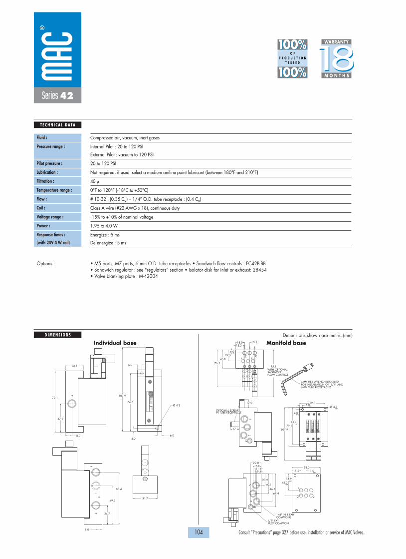
107.9
COMMONS1/4" IN & EXH
PILOT COMMON1/8" EXT.
FLOW CONTROL SANDWICHWITH OPTIONAL 95.1
6MM TUBE RECEPTACLESFOR INSTALLATION OF 1/4" AND 4MM HEX WRENCH REQURIED
TYP.
TYP.
TYP.
TYP.
TYP.
TYP.
TYP.
TYP.
TYP.TYP. Ø 4.3
45.333.9
10.518.5
67.456.5
40.1
23.2
22.016.9
9.511.1
76.5
52.06.0
79.175.4
4.0
37.622.5
6.0
15.310.518.5
MO
DE
L
AU
CK
LAN
D, N
.Z.
LIE
GE
, BE
LGIU
MW
IXO
M, M
I. U
SA
MO
DIF
.
MO
DE
L
AU
CK
LAN
D, N
.Z.
LIE
GE
, BE
LGIU
MW
IXO
M, M
I. U
SA
MO
DIF
.
CLCL CL
42
42
MO
DIF
.
AU
CK
LAN
D, N
.Z.
LIE
GE
, BE
LGIU
MW
IXO
M, M
I. U
SA
MO
DE
L
2
1
35
EP
EP
53
1
2
4
17.0
17.0
IN TUBE RECEPTACLEOPTIONAL SCREW
58.0
107.9
MO
DIF
.
AU
CK
LAN
D, N
.Z.
LIEG
E, B
ELG
IUM
WIX
OM
, MI. U
SA
MO
DE
L
37.2
79.1
8.04.0
74.7
6.0
6.0
Ø 4.3
8.0
23.1
24.7
49.9
67.4
31.7
13
X
2
p
1818100%100%
100%100% M O N T H S
WARRANTY
O FP R O D U C T I O N
T E S T E D
D I M E N S I O N S
T E C H N I C A L D A T A
Dimensions shown are metric (mm)
104 Consult “Precautions” page 327 before use, installation or service of MAC Valves..
Series 42
Fluid :
Pressure range :
Pilot pressure :
Lubrication :
Filtration :
Temperature range :
Flow :
Coil :
Voltage range :
Power :
Response times :
(with 24V 4 W coil)
Compressed air, vacuum, inert gases
Internal Pilot : 20 to 120 PSI
External Pilot : vacuum to 120 PSI
20 to 120 PSI
Not required, if used select a medium aniline point lubricant (between 180°F and 210°F)
40 µ
0°F to 120°F (-18°C to +50°C)
# 10-32 : (0.35 Cv) – 1/4” O.D. tube receptacle : (0.4 Cv)
Class A wire (#22 AWG x 18), continuous duty
-15% to +10% of nominal voltage
1.95 to 4.0 W
Energize : 5 ms
De-energize : 5 ms
• M5 ports, M7 ports, 6 mm O.D. tube receptacles • Sandwich flow controls : FC42B-BB • Sandwich regulator : see "regulators" section • Isolator disk for inlet or exhaust: 28454• Valve blanking plate : M-42004
Options :
Individual base Manifold base
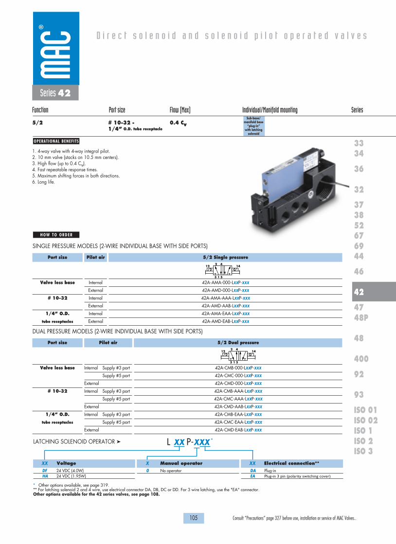
OPERATIONAL BENEFITS
D i r e c t s o l e n o i d a n d s o l e n o i d p i l o t o p e r a t e d v a l v e s
H O W T O O R D E R
105 Consult “Precautions” page 327 before use, installation or service of MAC Valves..
36
32
3738
3334
5267
46
44
47
42
400
48
92
93
ISO 1ISO 2 ISO 3
69
48P
ISO 01ISO 02
Series 42
Function Port size Flow (Max) Individual/Manifold mounting Series
5/2 # 10-32 - 0.4 Cv1/4” O.D. tube receptacle
1. 4-way valve with 4-way integral pilot.2. 10 mm valve (stacks on 10.5 mm centers).3. High flow (up to 0.4 Cv).4. Fast repeatable response times.5. Maximum shifting forces in both directions.6. Long life.
5/2 Single pressure
42A-AMA-000-LXXP-XXX
42A-AMD-000-LXXP-XXX
42A-AMA-AAA-LXXP-XXX
42A-AMD-AAB-LXXP-XXX
42A-AMA-EAA-LXXP-XXX
42A-AMD-EAB-LXXP-XXX
Port size
Valve less base
# 10-32
1/4” O.D.
tube receptacles
Pilot air
Internal
External
Internal
External
Internal
External
Sub-base/manifold base
“plug-in” with latching
solenoid
2 41412
1 53
SINGLE PRESSURE MODELS (2-WIRE INDIVIDUAL BASE WITH SIDE PORTS)
5/2 Dual pressure
42A-CMB-000-LXXP-XXX
42A-CMC-000-LXXP-XXX
42A-CMD-000-LXXP-XXX
42A-CMB-AAA-LXXP-XXX
42A-CMC-AAA-LXXP-XXX
42A-CMD-AAB-LXXP-XXX
42A-CMB-EAA-LXXP-XXX
42A-CMC-EAA-LXXP-XXX
42A-CMD-EAB-LXXP-XXX
Port size
Valve less base
# 10-32
1/4” O.D.
tube receptacles
Pilot air
Internal Supply #3 port
Supply #5 port
External
Internal Supply #3 port
Supply #5 port
External
Internal Supply #3 port
Supply #5 port
External
2 41412
1 53
DUAL PRESSURE MODELS (2-WIRE INDIVIDUAL BASE WITH SIDE PORTS)
Voltage
DF 24 VDC (4.0W)HA 24 VDC (1.95W)
Manual operator
0 No operator
Electrical connection**
DA Plug-inEA Plug-in 3 pin (polarity switching cover)
L XX P-XXX *LATCHING SOLENOID OPERATOR �
XX X XX
* Other options available, see page 319.** For latching solenoid 2 and 4 wire, use electrical connector DA, DB, DC or DD. For 3 wire latching, use the "EA" connector.Other options available for the 42 series valves, see page 108.

1818100%100%
100%100% M O N T H S
WARRANTY
O FP R O D U C T I O N
T E S T E D
D I M E N S I O N S
T E C H N I C A L D A T A
106 Consult “Precautions” page 327 before use, installation or service of MAC Valves..
1"-11 1/2 NPSM
COMMONS1/4" IN&EXH
EXT. PILOT1/8" COMMON
37.6
30.5
6.0
20.0
MO
DIF
.
AU
CK
LAN
D, N
.Z.
LIE
GE
, BE
LGIU
MW
IXO
M, M
I. U
SA
MO
DE
L
CO
ND
5
13
EP
2
4
9.511.1
16.923.0
26.0
23.2
40.1
56.5
67.594.4
6.0
11.0
4.0
TYP.
TYP.
TYP.
TYP.
TYP.
TYP.
66.5
Ø 4.3
24.5TYP.
75.3
46.0
75.3
A
TYP.24.5
TYP.Ø 4.3
TYP.
TYP.
TYP.
TYP.
114.0
45.2
33.8
20.0
66.5
TYP.TYP.
TYP.
TYP.
TYP.
TYP.
TYP.
4.0
11.0
6.0
94.467.5
56.5
40.1
23.2
26.023.0
16.911.19.5
4
2
4
2
EP
31
5
CO
ND
3
EP
1
5
CO
ND
4
2
4
2
LCLC LC LC
MO
DE
L
AU
CK
LAN
D, N
.Z.
LIE
GE
, BE
LGIU
MW
IXO
M, M
I. U
SA
MO
DIF
.
MO
DE
L
AU
CK
LAN
D, N
.Z.
LIE
GE
, BE
LGIU
MW
IXO
M, M
I. U
SA
MO
DIF
.
MO
DE
L
AU
CK
LAN
D, N
.Z.
LIE
GE
, BE
LGIU
MW
IXO
M, M
I. U
SA
MO
DIF
.
MO
DE
L
AU
CK
LAN
D, N
.Z.
LIE
GE
, BE
LGIU
MW
IXO
M, M
I. U
SA
MO
DIF
.
71.5
20.010.5
6.0
30.537.6
46.0
EXT. PILOT1/8" COMMON COMMONS
1/4" IN&EXH
1"-11 1/2 NPSM
Series 42
Fluid :
Pressure range :
Pilot pressure :
Lubrication :
Filtration :
Temperature range :
Flow :
Coil :
Voltage range :
Power :
Response times :
(with 24V 4 W coil)
Compressed air, vacuum, inert gases
Internal Pilot : 20 to 120 PSI
External Pilot : vacuum to 120 PSI
20 to 120 PSI
Not required, if used select a medium aniline point lubricant (between 180°F and 210°F)
40 µ
0°F to 120°F (-18°C to +50°C)
# 10-32 : (0.35 Cv) – 1/4” O.D. tube receptacle : (0.4 Cv)
Class A continuous duty, #22 AWG x 12 base leads
-15% to +10% of nominal voltage
1.95 to 4.0 W
Energize : 5 ms
De-energize : 5 ms
• M5 ports, M7 ports, 6 mm O.D. tube receptacles • Sandwich flow controls : FC42B-AB • Sandwich regulator : see "regulators" section • Isolator disk for inlet or exhaust: 28454• Valve blanking plate : M-42004 • Plug-in wire protector : 24180
Options :
Dimensions shown are metric (mm)Individual base Manifold base
Port
M4 Tube Fitting
M5 or 10-32
M7
A Dim.
2.70
3.20
3.40

D i r e c t s o l e n o i d a n d s o l e n o i d p i l o t o p e r a t e d v a l v e s
107 Consult “Precautions” page 327 before use, installation or service of MAC Valves..
36
32
3738
3334
5267
46
44
47
42
400
48
92
93
ISO 1ISO 2 ISO 3
69
48P
ISO 01ISO 02
Series 42
OPTIONS FOR NONPLUG-IN VALVES
42B-XMX-XXX-GXXX-XXX
M Pilot exhaust muffledP Pilot exhaust piped (# 10-32)U Pilot exhaust to main exhaust
42B-XXX-XJX-GXXX-XXX
J Manifold base – Side portsK Manifold base – Bottom portsL Left end manifold base – Side portsM Left end manifold base – Bottom portsN Right end manifold base – Side ports P Right end manifold base – Bottom ports
Base only :
Pilot style :
Manifold base
- Manifold base
Base type :Individual base
- Individual base
Universal spool
42B-000-XXX (i.e. 42B-000-AAL) 42B-000-XXX (i.e. 42B-000-AJL)
42B-XXX-XAX-GXXX-XXX
A Individual base – Side portsB Individual base – Bottom ports
42B-RXX-XXX-GXXX-XXX
R 2 position single solenoid universal spoolS 2 position double solenoid universal spool
42A-XXX-XAX-LXXX-XXX
A Individual base – Side portsB Individual base – Bottom portsJ Manifold base – Side portsK Manifold base – Bottom portsL Left end manifold base – Side portsM Left end manifold base – Bottom portsN Right end manifold base – Side portsP Right end manifold base – Bottom ports
Base/Manifold configurations for LATCHING SOLENOID VALVES :

D i r e c t s o l e n o i d a n d s o l e n o i d p i l o t o p e r a t e d v a l v e s
108 Consult “Precautions” page 327 before use, installation or service of MAC Valves..
42B-XXJ-XXX-GXXP-XST
J Internal pilot single pressureK Internal pilot dual pressure supply from #3 portL Internal pilot dual pressure supply from #5 portM External pilot
For LED with diode (2 & 3 position double solenoid valves)
42A-XXX-XXA-LXXP-XXX
A Plug-in Int. Pilot – 2 Wire LatchingB Plug-in Ext. Pilot – 2 Wire LatchingC Plug-in Int. Pilot – 3 Wire LatchingD Plug-in Ext. Pilot – 3 Wire LatchingE Plug-in Int. Pilot – 4 Wire LatchingF Plug-in Ext. Pilot – 4 Wire Latching
Base/Manifold options for int./ext. pilot for LATCHING SOLENOID VALVES :
Series 42
OPTIONS FORPLUG-IN VALVES
42B-XMX-XXX-GXXP-XXX
M Pilot exhaust muffledP Pilot exhaust piped (# 10-32)U Pilot exhaust to main exhaust
42B-XXX-XJX-GXXP-XXX
J Manifold base – Side portsK Manifold base – Bottom portsL Left end manifold base – Side portsM Left end manifold base – Bottom portsN Right end manifold base – Side ports P Right end manifold base – Bottom ports
Base only :
Pilot style :
Manifold base
- Manifold base wired for a single solenoid
Base type :Individual base
- Individual base wired for a double solenoid
Universal spool
42B-000-XXX (i.e. 42B-000-AAC) 42B-000-XXX (i.e. 42B-000-AJA)
42B-XXX-XAX-GXXP-XXX
A Individual base – Side portsB Individual base – Bottom ports
42B-RXX-XXX-GXXP-XXX
R 2 position single solenoid universal spoolS 2 position double solenoid universal spool
42A-XXX-XAX-LXXP-XXX
A Individual base – Side portsB Individual base – Bottom portsJ Manifold base – Side portsK Manifold base – Bottom portsL Left end manifold base – Side portsM Left end manifold base – Bottom portsN Right end manifold base – Side portsP Right end manifold base – Bottom ports
Base/Manifold configurations for LATCHING SOLENOID VALVES :

109 Consult “Precautions” page 327 before use, installation or service of MAC Valves..
Individual mounting Series
D i r e c t s o l e n o i d a n d s o l e n o i d p i l o t o p e r a t e d v a l v e s
SERIES FEATURES
36
32
3738
3334
5267
46
44
47
42
400
48
92
93
ISO 1ISO 2 ISO 3
69
48P
ISO 01ISO 02
Inline Sub-base non “plug-in”
Manifold base“plug-in”Stacking
Series 47
Manifold mounting
• Short stroke solenoid produces high energization shifting force.• High force return spring due to high force solenoid maximizes
both energization and de-energization shifting forces.• Built-in wear compensation - valve stroke is shorter than solenoid stroke.• Four (4) bonded balanced poppets on a one-piece valve stem.• End poppets seal first on conical seats and cushion inlet poppet, eliminating cutting.• Exhaust seals are not under inlet pressure thus reducing friction.• Short stroking balanced poppet allows for direct solenoid operation with high shifting forces,
minimized friction, fast response and high flow in a small package.
4
2
1
5
3
Push pin
Manual operator
Armature
Coil
“D” seal
Poppet
Valve return spring
Pole piece
Conical seat

OPERATIONAL BENEFITS
D i r e c t s o l e n o i d a n d s o l e n o i d p i l o t o p e r a t e d v a l v e s
H O W T O O R D E R
111 Consult “Precautions” page 327 before use, installation or service of MAC Valves..
36
32
3738
3334
5267
46
44
47
42
400
48
92
93
ISO 1ISO 2 ISO 3
69
48P
ISO 01ISO 02
Series 47
Function Port size Flow (Max) Individual Mounting Series
5/2 1/8” - 1/4” 0.5 Cv Inline
1. Short stroke solenoid produces highenergization shifting force.
2. High force return spring due to high forcesolenoid maximizes both energization andde-energization shifting forces.
3. Built-in wear compensation – valve stroke isshorter than solenoid stroke.
4. Four bonded balanced poppets on a one-piece valve stem.
5. End poppets seal first on conical seats andcushion inlet poppet, eliminating cutting.
6. Exhaust seals are not under inlet pressure thusreducing friction.
7. Integral non-rising flow controls available oninline models.
8. Short stroking balanced poppet allows fordirect solenoid operation with high shiftingforces, minimized friction, fast response andhigh flow in a small package.
Port size
1/8” NPTF
1/4” NPTF
Without flow controls
47A-AA0-H XXX-XXX
47A-AB0-H XXX-XXX
With flow controls
47A-BA0-H XXX-XXX
47A-BB0-H XXX-XXX
3
4
1
2
5
1412
3
4
1
2
5
1412
H XXX-XXX *SOLENOID OPERATOR �
Voltage
DA 24 VDC (5.2W)DB 24 VDC (2.4W)DC 24 VDC (1.8W)DD 24 VDC (1.0W)AA 120 VAC (6.7W)
Lead Wire length
A 18”B 24”C 36”
Manual operator
1 Non-locking recessed2 Locking recessed
Electrical connection
MA Plug-in wire assemblyMC Plug-in wire assembly with
lightBA Flying leadsBC Flying leads with lightMT Plug-in wire assembly with
rectifier & light
XX X X XX
* Other options available, see page 319.
* Other options available, see page 315.Note: AC voltage requires connector with rectifier.
L XXX-XXX *LATCHING OPERATOR �
Voltage
DA 24 VDC (5.2W)DF 12 VDC (5.2W)
Lead Wire length
A 18”B 24”C 36”
Manual operator
0 No operator
Electrical connection
BA 2 Wire Flying leads BJ 4 Wire Flying leadsLA 3 Wire Plug-in
(Polarity switching cover)MA 2 Wire Plug-inME 4 Wire Plug-in
XX X X XX
47A-CXO-HXXX-XXX
A 1/8” NPTFB 1/4” NPTF
Namur Mount Option (w/o flow controls)
O P T I O N S

24
9.7519.5
29.5
315
(2)TYP9.0
9.75
TYP. (2)MTG. HOLES4.25 DIA.
116.85
40.5
+
+ -
-
56.55
10.5
52.5
(2)TYP9.8
12
14
OPTIONAL FLOW CONTROL COVER
B
30.2
A
21.75
41.25
1818100%100%
100%100% M O N T H S
WARRANTY
O FP R O D U C T I O N
T E S T E D
D I M E N S I O N S
T E C H N I C A L D A T A
Dimensions shown are metric (mm)
112 Consult “Precautions” page 327 before use, installation or service of MAC Valves..
Series 47
Fluid :
Pressure range :
Lubrication :
Filtration :
Temperature range :
Flow :
Coil :
Voltage range :
Power :
Response times :
(with 5.2 W coil)
Compressed air, vacuum, inert gases
Vacuum to 120 PSI
Not required, if used select a medium aniline point lubricant (between 180°F and 210°F)
40 µ
0°F to 120°F (-18°C to +50°C)
5.2W : (0.50 Cv) – 2.4W : (0.35 Cv) – 1.0W : (0.30 Cv)
Class A wire (#22 AWG x 18), continuous duty
-15% to +10% of nominal voltage
5.2W – 2.4W – 1.0W
Energize : 17.4 ms
De-energize : 3.8 ms
• BSPP threads
• Flow control assembly : N-47004
Options :
Spare parts :
Dim
1/8”
1/4”
A
50.6
49.2
B
11.95
11.2

OPERATIONAL BENEFITS
D i r e c t s o l e n o i d a n d s o l e n o i d p i l o t o p e r a t e d v a l v e s
H O W T O O R D E R
113 Consult “Precautions” page 327 before use, installation or service of MAC Valves..
36
32
3738
3334
5267
46
44
47
42
400
48
92
93
ISO 1ISO 2 ISO 3
69
48P
ISO 01ISO 02
Series 47
Function Port size Flow (Max) Individual Mounting Series
5/2 1/8” - 1/4” 0.5 CvSub-base
non “plug-in”
1. Short stroke solenoid produces highenergization shifting force.
2. High force return spring due to high forcesolenoid maximizes both energization andde-energization shifting forces.
3. Built-in wear compensation – valve stroke isshorter than solenoid stroke.
4. Four bonded balanced poppets on a one-piece valve stem.
5. End poppets seal first on conical seats andcushion inlet poppet, eliminating cutting.
6. Exhaust seals are not under inlet pressure thusreducing friction.
7. Integral non-rising flow controls available oninline models.
8. Short stroking balanced poppet allows fordirect solenoid operation with high shiftingforces, minimized friction, fast response andhigh flow in a small package.
Port size
Valve less base
1/8” NPTF
1/4” NPTF
Without flow controls
47A-L10-H XXX-XXX
47A-LAA-H XXX-XXX
47A-LBA-H XXX-XXX
With flow controls
47A-L10-H XXX-XXX
47A-LAB-H XXX-XXX
47A-LBB-H XXX-XXX
3
4
1
2
5
1412
3
4
1
2
5
1412
H XXX-XXX *SOLENOID OPERATOR �
Voltage
DA 24 VDC (5.2W)DB 24 VDC (2.4W)DC 24 VDC (1.8W)DD 24 VDC (1.0W)AA 120 VAC (6.7W)
Lead Wire length
A 18”B 24”C 36”
Manual operator
1 Non-locking recessed2 Locking recessed
Electrical connection
MA Plug-in wire assemblyMC Plug-in wire assembly with
lightBA Flying leadsBC Flying leads with lightMT Plug-in wire assembly with
rectifier & light
XX X X XX
* Other options available, see page 319.
* Other options available, see page 315.Note: AC voltage requires connector with rectifier.
L XXX-XXX *LATCHING OPERATOR �
Voltage
DA 24 VDC (5.2W)DF 12 VDC (5.2W)
Lead Wire length
A 18”B 24”C 36”
Manual operator
0 No operator
Electrical connection
BA 2 Wire Flying leads BJ 4 Wire Flying leadsLA 3 Wire Plug-in
(Polarity switching cover)MA 2 Wire Plug-inME 4 Wire Plug-in
XX X X XX

67.0
TYP.(2) HOLES4.30 DIA.
APPROX
APPROX
D5.028.10
38.1
A
C
B
35.10
11.0
73.1
54.6
E
H
F
G
12
14
G- +
1
245
3
14
12
1818100%100%
100%100% M O N T H S
WARRANTY
O FP R O D U C T I O N
T E S T E D
D I M E N S I O N S
T E C H N I C A L D A T A
Dimensions shown are metric (mm)
114 Consult “Precautions” page 327 before use, installation or service of MAC Valves..
Series 47
Fluid :
Pressure range :
Lubrication :
Filtration :
Temperature range :
Flow :
Coil :
Voltage range :
Power :
Response times :
(with 5.2 W coil)
Compressed air, vacuum, inert gases
Vacuum to 120 PSI
Not required, if used select a medium aniline point lubricant (between 180°F and 210°F)
40 µ
0°F to 120°F (-18°C to +50°C)
5.2W : (0.50 Cv) – 2.4W : (0.35 Cv) – 1.0W : (0.30 Cv)
Class A wire (#22 AWG x 18), continuous duty
-15% to +10% of nominal voltage
5.2W – 2.4W – 1.0W
Energize : 17.4 ms
De-energize : 3.8 ms
• BSPP threads
• Pressure seal body to base: 16628 • Mounting screw (x2): 35043• Flow control assembly (x2): N-04001
Options :
Spare parts :
DIM.
1/8"
1/4"
A
8.0
9.5
B
22.9
24.0
C
48.6
48.8
D
19.05
23.0
E
9.5
12.5
F
12.5
12.8
G
34.2
34.2
H
59.0
57.2

OPERATIONAL BENEFITS
D i r e c t s o l e n o i d a n d s o l e n o i d p i l o t o p e r a t e d v a l v e s
H O W T O O R D E R
115 Consult “Precautions” page 327 before use, installation or service of MAC Valves..
36
32
3738
3334
5267
46
44
47
42
400
48
92
93
ISO 1ISO 2 ISO 3
69
48P
ISO 01ISO 02
Series 47
Function Port size Flow (Max) Manifold Mounting Series
5/2 1/8” - 1/4” 0.5 Cv Stacking
1. Short stroke solenoid produces highenergization shifting force.
2. High force return spring due to high forcesolenoid maximizes both energization andde-energization shifting forces.
3. Built-in wear compensation – valve stroke isshorter than solenoid stroke.
4. Four bonded balanced poppets on a one-piece valve stem.
5. End poppets seal first on conical seats andcushion inlet poppet, eliminating cutting.
6. Exhaust seals are not under inlet pressure thusreducing friction.
7. Integral non-rising flow controls available oninline models.
8. Short stroking balanced poppet allows fordirect solenoid operation with high shiftingforces, minimized friction, fast response andhigh flow in a small package.
Port size
1/8” NPTF
1/4” NPTF
Without flow controls
47A-SA0-H XXX-XXX
47A-SB0-H XXX-XXX
With flow controls
47A-TA0-H XXX-XXX
47A-TB0-H XXX-XXX
3
4
1
2
5
1412
3
4
1
2
5
1412
H XXX-XXX *SOLENOID OPERATOR �
Voltage
DA 24 VDC (5.2W)DB 24 VDC (2.4W)DC 24 VDC (1.8W)DD 24 VDC (1.0W)AA 120 VAC (6.7W)
Lead Wire length
A 18”B 24”C 36”
Manual operator
1 Non-locking recessed2 Locking recessed
Electrical connection
MA Plug-in wire assemblyMC Plug-in wire assembly with
lightBA Flying leadsBC Flying leads with lightMT Plug-in wire assembly with
rectifier & light
XX X X XX
* Other options available, see page 319.End plate kit required: M-47013-01 (1/4“ NPTF).
* Other options available, see page 315.Note: AC voltage requires connector with rectifier.
L XXX-XXX *LATCHING OPERATOR �
Voltage
DA 24 VDC (5.2W)DF 12 VDC (5.2W)
Lead Wire length
A 18”B 24”C 36”
Manual operator
0 No operator
Electrical connection
BA 2 Wire Flying leads BJ 4 Wire Flying leadsLA 3 Wire Plug-in
(Polarity switching cover)MA 2 Wire Plug-inME 4 Wire Plug-in
XX X X XX

4
22
4 4
2
95.0
TYP.Ø 6.3 THRU.
TYP.
TYP.30.7
5.3
TYP.
TYP.
TYP.
117.1
18.9
30.3
59.5
46.0
15.8TYP.Ø 6.3 THRU.
TYP.
TYP.
5.3
14.8
12
14
12
14
12
14
31
AUCKLAND,N.Z.LIEGE,BELGIUM
WATTS
MODIF. WIXOM,MI.,USA
ELECTRICAL
MODEL
13
TYP.
B
A
19.0
1818100%100%
100%100% M O N T H S
WARRANTY
O FP R O D U C T I O N
T E S T E D
D I M E N S I O N S
T E C H N I C A L D A T A
Dimensions shown are metric (mm)
116 Consult “Precautions” page 327 before use, installation or service of MAC Valves..
Series 47
Fluid :
Pressure range :
Lubrication :
Filtration :
Temperature range :
Flow :
Coil :
Voltage range :
Power :
Response times :
(with 5.2 W coil)
Compressed air, vacuum, inert gases
Vacuum to 120 PSI
Not required, if used select a medium aniline point lubricant (between 180°F and 210°F)
40 µ
0°F to 120°F (-18°C to +50°C)
5.2W : (0.50 Cv) – 2.4W : (0.35 Cv) – 1.0W : (0.30 Cv)
Class A wires (#22 AWG x 18), continuous duty
-15% to +10% of nominal voltage
5.2W – 2.4W – 1.0W
Energize : 17.4 ms
De-energize : 3.8 ms
• BSPP threads
• Inlet isolator: 28451 • Exhaust isolator: N-47009 • Tie Rod (x2): 79057
Options :
Spare parts :
Dim
1/8”
1/4”
A
22.8
24.2
B
18.4
19
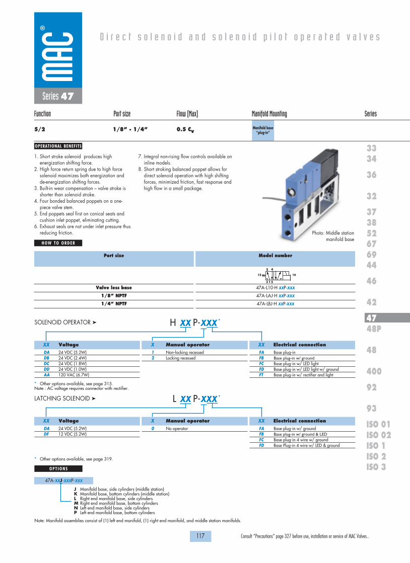
OPERATIONAL BENEFITS
D i r e c t s o l e n o i d a n d s o l e n o i d p i l o t o p e r a t e d v a l v e s
H O W T O O R D E R
117 Consult “Precautions” page 327 before use, installation or service of MAC Valves..
36
32
3738
3334
5267
46
44
47
42
400
48
92
93
ISO 1ISO 2 ISO 3
69
48P
ISO 01ISO 02
Series 47
Function Port size Flow (Max) Manifold Mounting Series
5/2 1/8” - 1/4” 0.5 CvManifold base
“plug-in”
1. Short stroke solenoid produces highenergization shifting force.
2. High force return spring due to high forcesolenoid maximizes both energization andde-energization shifting forces.
3. Built-in wear compensation – valve stroke isshorter than solenoid stroke.
4. Four bonded balanced poppets on a one-piece valve stem.
5. End poppets seal first on conical seats andcushion inlet poppet, eliminating cutting.
6. Exhaust seals are not under inlet pressure thusreducing friction.
7. Integral non-rising flow controls available oninline models.
8. Short stroking balanced poppet allows fordirect solenoid operation with high shiftingforces, minimized friction, fast response andhigh flow in a small package.
Port size
Valve less base
1/8” NPTF
1/4” NPTF
Model number
47A-L10-H XXP-XXX
47A-LAJ-H XXP-XXX
47A-LBJ-H XXP-XXX
3
4
1
2
5
1412
47A-XXJ-XXXP-XXX
O P T I O N S
J Manifold base, side cylinders (middle station)K Manifold base, bottom cylinders (middle station)L Right end manifold base, side cylindersM Right end manifold base, bottom cylindersN Left end manifold base, side cylindersP Left end manifold base, bottom cylinders
Note: Manifold assemblies consist of (1) left end manifold, (1) right end manifold, and middle station manifolds.
Voltage
DA 24 VDC (5.2W)DB 24 VDC (2.4W)DC 24 VDC (1.8W)DD 24 VDC (1.0W)AA 120 VAC (6.7W)
Manual operator
1 Non-locking recessed2 Locking recessed
Electrical connection
FA Base plug-inFB Base plug-in w/ groundFC Base plug-in w/ LED light FD Base plug-in w/ LED light w/ groundFT Base plug-in w/ rectifier and light
H XX P-XXX *SOLENOID OPERATOR �
XX X XX
* Other options available, see page 315.Note : AC voltage requires connector with rectifier.
Voltage
DA 24 VDC (5.2W)DF 12 VDC (5.2W)
Manual operator
0 No operator
Electrical connection
FA Base plug-in w/ groundFB Base plug-in w/ ground & LEDFC Base plug-in 4 wire w/ groundFD Base Plug-in 4 wire w/ LED & ground
L XX P-XXX *LATCHING SOLENOID �
XX X XX
* Other options available, see page 319.
Photo: Middle station manifold base

2
4
L
3
1
5
P
4
2
P
4
2
P
4
2
2
4
2
4P P P P
2
4
14
12
14
12
14
12
14
12
1
2
3
REGULATOR SHOWNOPTIONAL SANDWICH
112.7 101.0
83.0
21.5
41.9
63.3
100.5
19.8
21.732.7
127.4
4.823.5
18.0
96.3
5.530.8
51.678.2
32.518.0
23.5 18.0
9.0
24.5
200.8
BOTH ENDS3 HOLES3/8" N.P.T.F.
BOTH ENDSCONDUIT 1/2"-14 N.P.S.M.
AVAILABLE1/8" OR 1/4" PORTS
4 MTG. HOLESØ 5.3 DIA.
4
2
1818100%100%
100%100% M O N T H S
WARRANTY
O FP R O D U C T I O N
T E S T E D
D I M E N S I O N S
T E C H N I C A L D A T A
Dimensions shown are metric (mm)
118 Consult “Precautions” page 327 before use, installation or service of MAC Valves..
Series 47
Fluid :
Pressure range :
Lubrication :
Filtration :
Temperature range :
Flow (at 6 bar, ∆P=1bar) :
Coil :
Voltage range :
Power :
Response times :
(with 5,2 W coil)
Compressed air, vacuum, inert gases
Vacuum to 120 PSI
Not required, if used select a medium aniline point lubricant (between 180°F and 210°F)
40 µ
0°F to 120°F (-18°C to +50°C)
5.2W : (0.50 Cv) – 2.4W : (0.35 Cv) – 1.0W : (0.30 Cv)
Class A continuous duty, #22 AWG x 12 base leads
-15% to +10% of nominal voltage
5.2W – 2.4W – 1.0W
Energize : 17.4 ms
De-energize : 3.8 ms
• BSPP threads • Sandwich flow control: FC47A-AA • Sandwich regulator: see”Regulator” section
• Inlet/exhaust isolator: 28447 • Valve cover plate: M-47001
Options :
Spare parts :

119 Consult “Precautions” page 327 before use, installation or service of MAC Valves..
Individual mounting Series
D i r e c t s o l e n o i d a n d s o l e n o i d p i l o t o p e r a t e d v a l v e s
SERIES FEATURES
36
32
3738
3334
5267
46
44
47
42
400
48
92
93
ISO 1ISO 2 ISO 3
69
48P
ISO 01ISO 02
Series 48P
• High force MACSOLENOID®.• Integral 4-way pilot with poppet inside the spool.• Large flow in compact package.• Single or dual pressure.• Rectified AC voltage.
5
4 2
1 3
Manual operator
4-way pilot with“poppet in spool” design
Solenoid Bonded spool
Inline

OPERATIONAL BENEFITS
D i r e c t s o l e n o i d a n d s o l e n o i d p i l o t o p e r a t e d v a l v e s
H O W T O O R D E R
121 Consult “Precautions” page 327 before use, installation or service of MAC Valves..
36
32
3738
3334
5267
46
44
47
42
400
48
92
93
ISO 1ISO 2 ISO 3
69
48P
ISO 01ISO 02
Series 48P
Function Port size Flow (Max) Individual mounting Series
5/2 1/8” 1.0 Cv Inline
1. 4-way valve with 4-way pilot.2. Poppet in spool design3. 16 mm valve (stacks on 16.5 mm centers).4. High flow (up to 1.0 Cv).5. Fast repeatable response times.6. Maximum shifting forces in both directions.7. Long life.8. Compact design.
5/2 Single operatorSingle pressure
48PB-AAA-A00-GXXX-XXX
-
-
5/2 Single operatorDual pressure
-
48PB-CAB-A00-GXXX-XXX
48PB-CAC-A00-GXXX-XXX
Port size
1/8”
Pilot
Internal
Internal from port 3
Internal from port 5
24 1214
31
5
2 412 14
3 1 5
G XXX-XXX *STANDARD SOLENOID OPERATOR �
Voltage
AA 120 VAC (2.5W)DC 24 VDC (1.8W)DD 24 VDC (2.5W)DF 24 VDC (4.0W)
Wire length
A 18”B 24”C 36”
Manual operator
1 Non-locking2 Locking
Electrical connection
BA Flying leadsBT Flying leads with lightGA MAC JAC solenoid plug-inKA Plug-in wire assy.KT Plug-in wire assy. with lightKD Plug-in wire assy. with
rectifier & light & ground
XX X X XX
* Other options available, see page 311.Note : AC voltage requires connector with rectifier.
48PB-X X X-X00-GXX-XXX
O P T I O N S
A Pilot exhaust muffledC Pilot exhaust piped M5D Pilot exhaust out main exhaust

24
VAC TO 150 PSI MODIF.
AUCKLAND, N.Z.LIEGE, BELGIUMWIXOM, MI. USA
MODEL
35 1
8.016.0
16.0 33.4
113.0
1/8"- BSPP (5 PLACES)
4.735.5
56.3 13.2
82.8Ø 4.2
8.0
15.5
15.5
25.9
1818100%100%
100%100% M O N T H S
WARRANTY
O FP R O D U C T I O N
T E S T E D
D I M E N S I O N S
T E C H N I C A L D A T A
Dimensions shown are metric (mm)
122 Consult “Precautions” page 327 before use, installation or service of MAC Valves..
Series 48P
Fluid :
Pressure range :
Lubrication :
Filtration :
Temperature range :
Flow :
Coil :
Voltage range :
Power :
Compressed air, vacuum, inert gases
25 to 120 PSI
Not required, if used select a medium aniline point lubricant (between 180°F and 210°F)
40 µ
0°F to 120°F (18°C to +50°C)
Cv 1,0
Class A wire continuous duty, #22 AWG x 18 leads
-15% to +10% of nominal voltage
1.0 to 4.0 W
• BSPP threadsOptions :
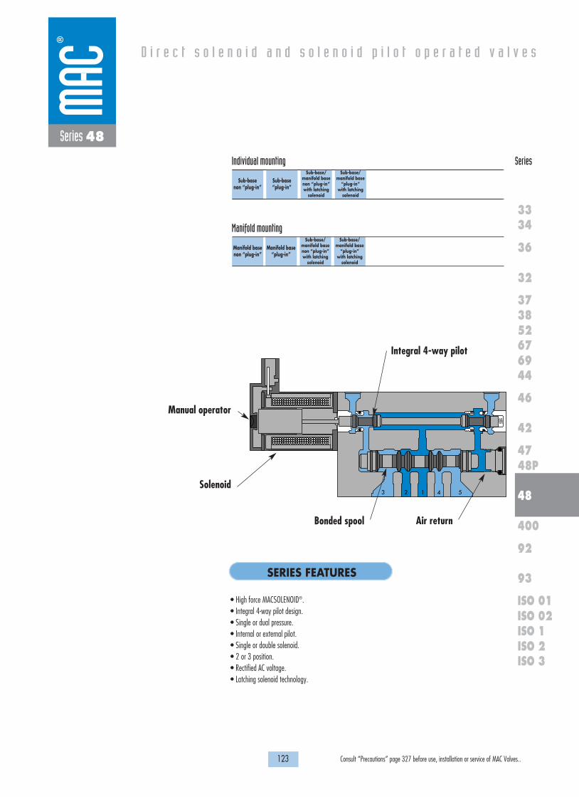
123 Consult “Precautions” page 327 before use, installation or service of MAC Valves..
Individual mounting Series
D i r e c t s o l e n o i d a n d s o l e n o i d p i l o t o p e r a t e d v a l v e s
SERIES FEATURES
36
32
3738
3334
5267
46
44
47
42
400
48
92
93
ISO 1ISO 2 ISO 3
69
48P
ISO 01ISO 02
Series 48
• High force MACSOLENOID®.• Integral 4-way pilot design.• Single or dual pressure.• Internal or external pilot.• Single or double solenoid.• 2 or 3 position.• Rectified AC voltage.• Latching solenoid technology.
3 2 1 4 5
Manual operator
Integral 4-way pilot
Solenoid
Air returnBonded spool
Sub-base non “plug-in”
Sub-base“plug-in”
Sub-base/manifold basenon “plug-in” with latching
solenoid
Sub-base/manifold base
“plug-in” with latching
solenoid
Manifold base“plug-in”
Sub-base/manifold basenon “plug-in” with latching
solenoid
Sub-base/manifold base
“plug-in” with latching
solenoid
Manifold basenon “plug-in”
Manifold mounting

OPERATIONAL BENEFITS
D i r e c t s o l e n o i d a n d s o l e n o i d p i l o t o p e r a t e d v a l v e s
H O W T O O R D E R
125 Consult “Precautions” page 327 before use, installation or service of MAC Valves..
36
32
3738
3334
5267
46
44
47
42
400
48
92
93
ISO 1ISO 2 ISO 3
69
48P
ISO 01ISO 02
5/2Single solenoid
48B-AMA-000-GXXX-XXX
48B-AMD-000-GXXX-XXX
48B-AMA-AAL-GXXX-XXX
48B-AMD-AAM-GXXX-XXX
5/2Double solenoid
48B-BMA-000-GXXX-XXX
48B-BMD-000-GXXX-XXX
48B-BMA-AAL-GXXX-XXX
48B-BMD-AAM-GXXX-XXX
5/3Closed center
48B-EMA-000-GXXX-XXX
48B-EMD-000-GXXX-XXX
48B-EMA-AAL-GXXX-XXX
48B-EMD-AAM-GXXX-XXX
5/3Open center
48B-FMA-000-GXXX-XXX
48B-FMD-000-GXXX-XXX
48B-FMA-AAL-GXXX-XXX
48B-FMD-AAM-GXXX-XXX
2 412 14
3 1 5
2 412 14
3 1 5
2 412 14
3 1 5
2 412 14
3 1 5
Port size
Valve less
base
1/8” NPTF
Pilot air
Internal
External
Internal
External
Series 48
Function Port size Flow (Max) Individual mounting Series
5/2, 5/3 1/8” 1.1 CvSub-base
non “plug-in”
1. 4-way valve with 4-way integral pilot.2. 16 mm valve (stacks on 16.5 mm centers).3. High flow (up to 1.1 Cv).4. Fast repeatable response times.5. Maximum shifting forces in both directions.6. Long life.
SINGLE PRESSURE MODELS (VALVE WITH BASE CODED FOR SIDE PORTS)
5/2Single solenoid
48B-CMB-000-GXXX-XXX
48B-CMC-000-GXXX-XXX
48B-CMD-000-GXXX-XXX
48B-CMB-AAL-GXXX-XXX
48B-CMC-AAL-GXXX-XXX
48B-CMD-AAM-GXXX-XXX
5/2Double solenoid
48B-DMB-000-GXXX-XXX
48B-DMC-000-GXXX-XXX
48B-DMD-000-GXXX-XXX
48B-DMB-AAL-GXXX-XXX
48B-DMC-AAL-GXXX-XXX
48B-DMD-AAM-GXXX-XXX
5/3Pressure center
48B-HMB-000-GXXX-XXX
48B-HMC-000-GXXX-XXX
48B-HMD-000-GXXX-XXX
48B-HMB-AAL-GXXX-XXX
48B-HMC-AAL-GXXX-XXX
48B-HMD-AAM-GXXX-XXX
Port size
Valve less base
1/8” NPTF
Pilot air
Internal Supply #3 port
Supply #5 port
External
Internal Supply #3 port
Supply #5 port
External
DUAL PRESSURE MODELS (VALVE WITH BASE CODED FOR SIDE PORTS)
G XXX-XXX *STANDARD SOLENOID OPERATOR �
Voltage
AA 120 VAC (2.5W)DC 24 VDC (1.8W)DD 24 VDC (2.5W)DF 24 VDC (4.0W)
Wire length
A 18”B 24”C 36”
Manual operator
1 Non-locking recessed2 Locking recessed
Electrical connection
BA Flying leadsBT Flying leads with lightGA MAC JAC solenoid plug-inKA Plug-in wire assy.KT Plug-in wire assy. with lightKD Plug-in wire assy. with
rectifier & light & ground
XX X X XX
* Other options available, see page 311.Latching solenoid also available, see page 133.Note : AC voltage requires connector with rectifier.Other options available for the 48 series valves, see page 137.
24 1214
31
5
24 1214
31
5
2 412 14
3 1 5

P
1
35
EP
MO
DEL
AU
CKLA
ND
, N.Z.
LIEGE, BELG
IUM
WIXO
M, M
I. USA
MO
DIF.
VAC
TO 150 PSI
116.9APPROX.
86.00
APPROX.
4
2
15.3
24.9
12.0
16.7
21.5
29.5
46.1
69.2
COMMONS3/8" IN & EXH
PILOT COMMON1/8" EXT.
Ø 5.3TYP.
1/8" PORTS
50.4
6.3
4.5
5.0
9.7
23.3
8.0
29.0
13.9
1818100%100%
100%100% M O N T H S
WARRANTY
O FP R O D U C T I O N
T E S T E D
D I M E N S I O N S
T E C H N I C A L D A T A
Dimensions shown are metric (mm)
126 Consult “Precautions” page 327 before use, installation or service of MAC Valves..
Series 48
Fluid :
Pressure range :
Pilot pressure :
Lubrication :
Filtration :
Temperature range :
Flow :
Coil :
Voltage range :
Power :
Response times :
(with 4 W coil)
Compressed air, vacuum, inert gases
Internal pilot: 2 pos.: 20 to 120 PSI - 3 pos.: 35 to 120 PSI
External pilot: vacuum to 120 PSI
2 position : 20 to 120 PSI - 3 position : 35 to 120 PSI
Not required, if used select a medium aniline point lubricant (between 180°F and 210°F)
40 µ
0°F to 120°F (-18°C to +50°C)
1/8" side ports: (1.0 Cv) – 1/8" bottom ports : (1.1 Cv)
Class A wire (#22 AWG x 18), continuous duty
-15% to +10% of nominal voltage
1.0 to 4.0 W
Energize : 6 ms
De-energize : 6 ms
• BSPP threads • 1/4” O.D. pressed in tube receptacles • Sandwich Flow controls: FC48B-BB • Sandwich regulator: see "regulators" section
Options :

OPERATIONAL BENEFITS
D i r e c t s o l e n o i d a n d s o l e n o i d p i l o t o p e r a t e d v a l v e s
H O W T O O R D E R
127 Consult “Precautions” page 327 before use, installation or service of MAC Valves..
36
32
3738
3334
5267
46
44
47
42
400
48
92
93
ISO 1ISO 2 ISO 3
69
48P
ISO 01ISO 02
5/2Single solenoid
48B-AMA-000-GXXP-XXX
48B-AMD-000-GXXP-XXX
48B-AMA-AAA-GXXP-XXX
48B-AMD-AAB-GXXP-XXX
5/3Double solenoid
48B-BME-000-GXXP-XST
48B-BMH-000-GXXP-XST
48B-BME-AAC-GXXP-XST
48B-BMH-AAD-GXXP-XST
5/3Closed center
48B-EME-000-GXXP-XST
48B-EMH-000-GXXP-XST
48B-EME-AAC-GXXP-XST
48B-EMH-AAD-GXXP-XST
5/3Open center
48B-FME-000-GXXP-XST
48B-FMH-000-GXXP-XST
48B-FME-AAC-GXXP-XST
48B-FMH-AAD-GXXP-XST
2 412 14
3 1 5
2 412 14
3 1 5
2 412 14
3 1 5
2 412 14
3 1 5
Port size
Valve less
base
1/8” NPTF
Pilot air
Internal
External
Internal
External
Series 48
Function Port size Flow (Max) Individual mounting Series
5/2, 5/3 1/8” 1.1 CvSub-base“plug-in”
1. 4-way valve with 4-way integral pilot.2. 16 mm valve (stacks on 16.5 mm centers).3. High flow (up to 1.1 Cv).4. Fast repeatable response times.5. Maximum shifting forces in both directions.6. Long life.
SINGLE PRESSURE MODELS (LED STANDARD EXCEPT FOR SINGLE SOLENOIDS) - VALVE WITH BASE CODED FOR SIDE PORTS
5/2Single solenoid
48B-CMB-000-GXXP-XXX
48B-CMC-000-GXXP-XXX
48B-CMD-000-GXXP-XXX
48B-CMB-AAA-GXXP-XXX
48B-CMC-AAA-GXXP-XXX
48B-CMD-AAB-GXXP-XXX
5/2Double solenoid
48B-DMF-000-GXXP-XST
48B-DMG-000-GXXP-XST
48B-DMH-000-GXXP-XST
48B-DMF-AAC-GXXP-XST
48B-DMG-AAC-GXXP-XST
48B-DMH-AAD-GXXP-XST
5/3Pressure center
48B-HMF-000-GXXP-XST
48B-HMG-000-GXXP-XST
48B-HMH-000-GXXP-XST
48B-HMF-AAC-GXXP-XST
48B-HMG-AAC-GXXP-XST
48B-HMH-AAD-GXXP-XST
Port size
Valve less base
1/8” NPTF
Pilot air
Internal Supply #3 port
Supply #5 port
External
Internal Supply #3 port
Supply #5 port
External
DUAL PRESSURE MODELS (LED STANDARD EXCEPT FOR SINGLE SOLENOIDS) - VALVE WITH BASE CODED FOR SIDE PORTS
Voltage
AA 120 VAC (2.5W)DC 24 VDC (1.8W)DD 24 VDC (2.5W)DF 24 VDC (4.0W)
Manual operator
1 Non-locking recessed2 Locking recessed
Electrical connection
Double solenoid & 3 position modelsST Base plug-inSingle solenoid modelsSA Base plug-inSJ Base plug-in with LED lightSS Base plug-in with rectifier & light & ground
G XX P-XXX *STANDARD SOLENOID OPERATOR �
XX X XX
* Other options available, see page 311.Latching solenoid also available, see page 135.Note : AC voltage requires connector with rectifier (For double solenoid consult factory).Other options available for the 48 series valves, see page 138.
24 1214
31
5
24 1214
31
5
2 412 14
3 1 5
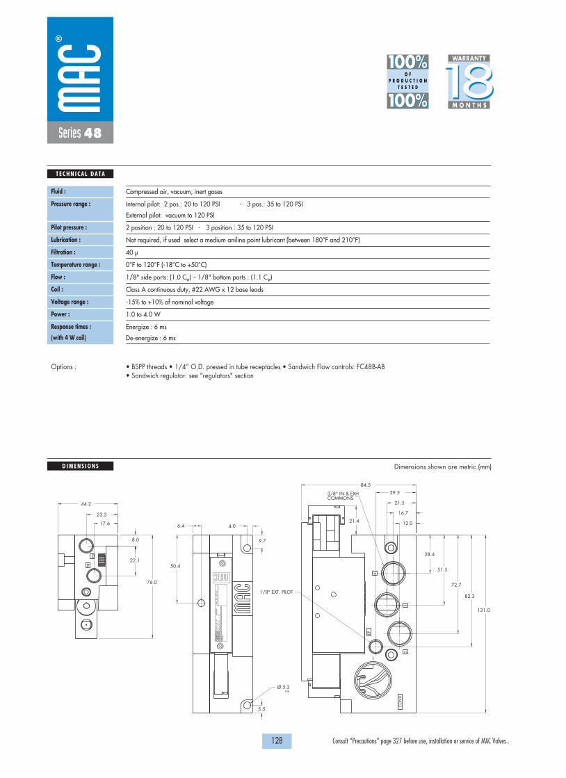
3
5
1
EP
CO
ND
2
4
MO
DEL
AU
CKL
AN
D, N
.Z.
LIEG
E, B
ELG
IUM
WIX
OM
, MI.
USA
MO
DIF
.VA
C T
O 1
50 P
SI
17.6
23.3
8.0
22.1
76.0
12.0
16.7
21.5
29.5
28.4
51.5
72.7
82.3
131.0
COMMONS3/8" IN & EXH
Ø 5.3TYP.
1/8" EXT. PILOT
44.2
6.4 4.0
50.4
9.7
5.5
84.5
21.4
1818100%100%
100%100% M O N T H S
WARRANTY
O FP R O D U C T I O N
T E S T E D
D I M E N S I O N S
T E C H N I C A L D A T A
Dimensions shown are metric (mm)
128 Consult “Precautions” page 327 before use, installation or service of MAC Valves..
Series 48
Fluid :
Pressure range :
Pilot pressure :
Lubrication :
Filtration :
Temperature range :
Flow :
Coil :
Voltage range :
Power :
Response times :
(with 4 W coil)
Compressed air, vacuum, inert gases
Internal pilot: 2 pos.: 20 to 120 PSI - 3 pos.: 35 to 120 PSI
External pilot: vacuum to 120 PSI
2 position : 20 to 120 PSI - 3 position : 35 to 120 PSI
Not required, if used select a medium aniline point lubricant (between 180°F and 210°F)
40 µ
0°F to 120°F (-18°C to +50°C)
1/8" side ports: (1.0 Cv) – 1/8" bottom ports : (1.1 Cv)
Class A continuous duty, #22 AWG x 12 base leads
-15% to +10% of nominal voltage
1.0 to 4.0 W
Energize : 6 ms
De-energize : 6 ms
• BSPP threads • 1/4” O.D. pressed in tube receptacles • Sandwich Flow controls: FC48B-AB • Sandwich regulator: see "regulators" section
Options :

OPERATIONAL BENEFITS
D i r e c t s o l e n o i d a n d s o l e n o i d p i l o t o p e r a t e d v a l v e s
H O W T O O R D E R
129 Consult “Precautions” page 327 before use, installation or service of MAC Valves..
36
32
3738
3334
5267
46
44
47
42
400
48
92
93
ISO 1ISO 2 ISO 3
69
48P
ISO 01ISO 02
5/2Single solenoid
48B-AMA-000-GXXX-XXX
48B-AMD-000-GXXX-XXX
48B-AMA-AJL-GXXX-XXX
48B-AMD-AJM-GXXX-XXX
5/2Double solenoid
48B-BMA-000-GXXX-XXX
48B-BMD-000-GXXX-XXX
48B-BMA-AJL-GXXX-XXX
48B-BMD-AJM-GXXX-XXX
5/3Closed center
48B-EMA-000-GXXX-XXX
48B-EMD-000-GXXX-XXX
48B-EMA-AJL-GXXX-XXX
48B-EMD-AJM-GXXX-XXX
5/3Open center
48B-FMA-000-GXXX-XXX
48B-FMD-000-GXXX-XXX
48B-FMA-AJL-GXXX-XXX
48B-FMD-AJM-GXXX-XXX
2 412 14
3 1 5
2 412 14
3 1 5
2 412 14
3 1 5
2 412 14
3 1 5
Port size
Valve less
base
1/8” NPTF
Pilot air
Internal
External
Internal
External
Series 48
Function Port size Flow (Max) Manifold mounting Series
5/2, 5/3 1/8” 1.1 CvManifold basenon “plug-in”
1. 4-way valve with 4-way integral pilot.2. 16 mm valve (stacks on 16.5 mm centers).3. High flow (up to 1.1 Cv).4. Fast repeatable response times.5. Maximum shifting forces in both directions.6. Long life.
SINGLE PRESSURE MODELS (MIDDLE STATION MANIFOLDS WITH SIDE PORTS)
5/2Single solenoid
48B-CMB-000-GXXX-XXX
48B-CMC-000-GXXX-XXX
48B-CMD-000-GXXX-XXX
48B-CMB-AJL-GXXX-XXX
48B-CMC-AJL-GXXX-XXX
48B-CMD-AJM-GXXX-XXX
5/2Double solenoid
48B-DMB-000-GXXX-XXX
48B-DMC-000-GXXX-XXX
48B-DMD-000-GXXX-XXX
48B-DMB-AJL-GXXX-XXX
48B-DMC-AJL-GXXX-XXX
48B-DMD-AJM-GXXX-XXX
5/3Pressure center
48B-HMB-000-GXXX-XXX
48B-HMC-000-GXXX-XXX
48B-HMD-000-GXXX-XXX
48B-HMB-AJL-GXXX-XXX
48B-HMC-AJL-GXXX-XXX
48B-HMD-AJM-GXXX-XXX
Port size
Valve less base
1/8” NPTF
Pilot air
Internal Supply #3 port
Supply #5 port
External
Internal Supply #3 port
Supply #5 port
External
DUAL PRESSURE MODELS (MIDDLE STATION MANIFOLDS WITH SIDE PORTS)
G XXX-XXX *STANDARD SOLENOID OPERATOR �
Voltage
AA 120 VAC (2.5W)DC 24 VDC (1.8W)DD 24 VDC (2.5W)DF 24 VDC (4.0W)
Wire length
A 18”B 24”C 36”
Manual operator
1 Non-locking recessed2 Locking recessed
Electrical connection
BA Flying leadsBT Flying leads with lightGA MAC JAC solenoid plug-inKA Plug-in wire assy.KT Plug-in wire assy. with lightKD Plug-in wire assy. with
rectifier & light & ground
XX X X XX
* Other options available, see page 311.Latching solenoid also available, see page 133.Note : - AC voltage requires connector with rectifier.
- Manifold assemblies consist of (1) left end manifold, (1) right endmanifold, and middle station manifolds (options "J" or "K").
Other options available for the 48 series valves, see page 137.
24 1214
31
5
24 1214
31
5
2 412 14
3 1 5

1818100%100%
100%100% M O N T H S
WARRANTY
O FP R O D U C T I O N
T E S T E D
D I M E N S I O N S
T E C H N I C A L D A T A
Dimensions shown are metric (mm)
130 Consult “Precautions” page 327 before use, installation or service of MAC Valves..
P
2
1
35
EP
4
2 P2
4
MO
DEL
AU
CKLA
ND
, N.Z.
LIEGE, BELG
IUM
WIXO
M, M
I. USA
MO
DIF.
VAC
TO 150 PSI
MO
DEL
AU
CKLA
ND
, N.Z.
LIEGE, BELG
IUM
WIXO
M, M
I. USA
MO
DIF.
VAC
TO 150 PSI
MO
DEL
AU
CKLA
ND
, N.Z.
LIEGE, BELG
IUM
WIXO
M, M
I. USA
MO
DIF.
VAC
TO 150 PSI
116.9APPROX.
86.00APPROX.
MO
DEL
AU
CKLA
ND
, N.Z.
LIEGE, BELG
IUM
WIXO
M, M
I. USA
MO
DIF.
VAC
TO 150 PSI
4
2
4
2 P
96.0
4.8
86.8
4.7
83.0
TYP.
TYP.
31.5 16.5
17.65.7
16.5
15.3
24.9
12.0
16.7
21.5
29.5
46.1
69.2
COMMONS3/8" IN & EXH
PILOT COMMON1/8" EXT.
Ø 5.3TYP.
1/8" PORTS
135.5
Series 48
Fluid :
Pressure range :
Pilot pressure :
Lubrication :
Filtration :
Temperature range :
Flow :
Coil :
Voltage range :
Power :
Response times :
(with 4 W coil)
Compressed air, vacuum, inert gases
Internal pilot: 2 pos.: 20 to 120 PSI - 3 pos.: 35 to 120 PSI
External pilot: vacuum to 120 PSI
2 position : 20 to 120 PSI - 3 position : 35 to 120 PSI
Not required, if used select a medium aniline point lubricant (between 180°F and 210°F)
40 µ
0°F to 120°F (-18°C to +50°C)
1/8" side ports: (1.0 Cv) – 1/8" bottom ports : (1.1 Cv)
Class A wire (#22 AWG x 18), continuous duty
-15% to +10% of nominal voltage
1.0 to 4.0 W
Energize : 6 ms
De-energize : 6 ms
• BSPP threads • 1/4” O.D. pressed in tube receptacles • Sandwich flow controls: FC48B-BB • Sandwich regulator: see "regulators" section• Valve blanking plate: M-48004 • Isolator disk for inlet/exhaust: 28471
Options :

OPERATIONAL BENEFITS
D i r e c t s o l e n o i d a n d s o l e n o i d p i l o t o p e r a t e d v a l v e s
H O W T O O R D E R
131 Consult “Precautions” page 327 before use, installation or service of MAC Valves..
36
32
3738
3334
5267
46
44
47
42
400
48
92
93
ISO 1ISO 2 ISO 3
69
48P
ISO 01ISO 02
5/2Single solenoid
48B-AMA-000-GXXP-XXX
48B-AMD-000-GXXP-XXX
48B-AMA-AJA-GXXP-XXX
48B-AMD-AJB-GXXP-XXX
5/2Double solenoid
48B-BME-000-GXXP-XST
48B-BMH-000-GXXP-XST
48B-BME-AJC-GXXP-XST
48B-BMH-AJD-GXXP-XST
5/3Closed center
48B-EME-000-GXXP-XST
48B-EMH-000-GXXP-XST
48B-EME-AJC-GXXP-XST
48B-EMH-AJD-GXXP-XST
5/3Open center
48B-FME-000-GXXP-XST
48B-FMH-000-GXXP-XST
48B-FME-AJC-GXXP-XST
48B-FMH-AJD-GXXP-XST
2 412 14
3 1 5
2 412 14
3 1 5
2 412 14
3 1 5
2 412 14
3 1 5
Port size
Valve less
base
1/8” NPTF
Pilot air
Internal
External
Internal
External
Series 48
Function Port size Flow (Max) Manifold mounting Series
5/2, 5/3 1/8” 1.1 CvManifold base
“plug-in”
1. 4-way valve with 4-way integral pilot.2. 16 mm valve (stacks on 16.5 mm centers).3. High flow (up to 1.1 Cv).4. Fast repeatable response times.5. Maximum shifting forces in both directions.6. Long life.
SINGLE PRESSURE MODELS (LED STANDARD EXCEPT FOR SINGLE SOLENOIDS)
5/2Single solenoid
48B-CMB-000-GXXP-XXX
48B-CMC-000-GXXP-XXX
48B-CMD-000-GXXP-XXX
48B-CMB-AJA-GXXP-XXX
48B-CMC-AJA-GXXP-XXX
48B-CMD-AJB-GXXP-XXX
5/2Double solenoid
48B-DMF-000-GXXP-XST
48B-DMG-000-GXXP-XST
48B-DMH-000-GXXP-XST
48B-DMF-AJC-GXXP-XST
48B-DMG-AJC-GXXP-XST
48B-DMH-AJD-GXXP-XST
5/3Pressure center
48B-HMF-000-GXXP-XST
48B-HMG-000-GXXP-XST
48B-HMH-000-GXXP-XST
48B-HMF-AJC-GXXP-XST
48B-HMG-AJC-GXXP-XST
48B-HMH-AJD-GXXP-XST
Port size
Valve less base
1/8” NPTF
Pilot air
Internal Supply #3 port
Supply #5 port
External
Internal Supply #3 port
Supply #5 port
External
DUAL PRESSURE MODELS (LED STANDARD EXCEPT FOR SINGLE SOLENOIDS)
Voltage
AA 120 VAC (2.5W)DC 24 VDC (1.8W)DD 24 VDC (2.5W)DF 24 VDC (4.0W)
Manual operator
1 Non-locking recessed2 Locking recessed
Electrical connection
Double solenoid & 3 position modelsST Base plug-inSingle solenoid modelsSA Base plug-inSJ Base plug-in with LED lightSS Base plug-in with rectifier & light & ground
G XX P-XXX *STANDARD SOLENOID OPERATOR �
XX X XX
* Other options available, see page 311.Latching solenoid also available, see page 135.Note : - AC voltage requires connector with rectifier. (For double solenoid consult factory).
- Manifold assemblies consist of (1) left end manifold, (1) right end manifold, andmiddle station manifolds (options "J" or "K").
Other options available for the 48 series valves, see page 138.
Above numbers are middle station manifolds with side ports
24 1214
31
5
24 1214
31
5
2 412 14
3 1 5

1818100%100%
100%100% M O N T H S
WARRANTY
O FP R O D U C T I O N
T E S T E D
D I M E N S I O N S
T E C H N I C A L D A T A
Dimensions shown are metric (mm)
132 Consult “Precautions” page 327 before use, installation or service of MAC Valves..
3
5
1
EP
CO
ND
2 2
44
MO
DEL
AU
CKL
AN
D, N
.Z.
LIEG
E, B
ELG
IUM
WIX
OM
, MI.
USA
MO
DIF
.VA
C T
O 1
50 P
SI
VAC
TO
150
PSI
MO
DIF
.
AU
CKL
AN
D, N
.Z.
LIEG
E, B
ELG
IUM
WIX
OM
, MI.
USA
MO
DEL
MO
DEL
AU
CKL
AN
D, N
.Z.
LIEG
E, B
ELG
IUM
WIX
OM
, MI.
USA
MO
DIF
.VA
C T
O 1
50 P
SI
VAC
TO
150
PSI
MO
DIF
.
AU
CKL
AN
D, N
.Z.
LIEG
E, B
ELG
IUM
WIX
OM
, MI.
USA
MO
DEL
2
4 4
2
17.623.316.5
31.5
8.0
22.1
4.0 88.0TYP.
76.0
9.7
115.8
TYP.
TYP.
TYP.
TYP.TYP.
12.0
16.7
21.5
29.5
28.4
51.5
72.7
82.3
131.0
COMMONS3/8" IN & EXH
Ø 5.3TYP.
1/8" PORTS
1/8" EXT. PILOT
84.5
21.4
Series 48
Fluid :
Pressure range :
Pilot pressure :
Lubrication :
Filtration :
Temperature range :
Flow :
Coil :
Voltage range :
Power :
Response times :
(with 4 W coil)
Compressed air, vacuum, inert gases
Internal pilot: 2 pos.: 20 to 120 PSI - 3 pos.: 35 to 120 PSI
External pilot: vacuum to 120 PSI
2 position : 20 to 120 PSI - 3 position : 35 to 120 PSI
Not required, if used select a medium aniline point lubricant (between 180°F and 210°F)
40 µ
0°F to 120°F (-18°C to +50°C)
1/8" side ports: (1.0 Cv) – 1/8" bottom ports : (1.1 Cv)
Class A wire (#22 AWG x 18), continuous duty
-15% to +10% of nominal voltage
1.0 to 4.0 W
Energize : 6 ms
De-energize : 6 ms
• BSPP threads • 1/4” O.D. pressed in tube receptacles • Sandwich flow controls: FC48B-AB • Sandwich regulator: see "regulators" section• Valve blanking plate: M-48004 • Isolator disk for inlet/exhaust: 28471• Plug-in wire protector: 24180
Options :

OPERATIONAL BENEFITS
D i r e c t s o l e n o i d a n d s o l e n o i d p i l o t o p e r a t e d v a l v e s
H O W T O O R D E R
133 Consult “Precautions” page 327 before use, installation or service of MAC Valves..
36
32
3738
3334
5267
46
44
47
42
400
48
92
93
ISO 1ISO 2 ISO 3
69
48P
ISO 01ISO 02
Series 48
Function Port size Flow (Max) Individual/Manifold mounting Series
5/2 1/8” 1.1 Cv
Sub-base/manifold basenon “plug-in” with latching
solenoid
1. 4-way valve with 4-way integral pilot.2. 16 mm valve (stacks on 16.5 mm centers).3. High flow (up to 1.1 Cv).4. Fast repeatable response times.5. Maximum shifting forces in both directions.6. Long life.
5/2Single pressure
48A-AMA-000-LXXX-XXX
48A-AMD-000-LXXX-XXX
48A-AMA-AAL-LXXX-XXX
48A-AMD-AAM-LXXX-XXX
Port size
Valve less base
1/8” NPTF
Pilot air
Internal
External
Internal
External
SINGLE PRESSURE MODELS (INDIVIDUAL BASE WITH SIDE PORTS)
5/2Dual pressure
48A-CMB-000-LXXX-XXX
48A-CMC-000-LXXX-XXX
48A-CMD-000-LXXX-XXX
48A-CMB-AAL-LXXX-XXX
48A-CMC-AAL-LXXX-XXX
48A-CMD-AAM-LXXX-XXX
Port size
Valve less base
1/8” NPTF
Pilot air
Internal Supply #3 port
Supply #5 port
External
Internal Supply #3 port
Supply #5 port
External
DUAL PRESSURE MODELS (INDIVIDUAL BASE WITH SIDE PORTS)
2 412 14
3 1 5
2 412 14
3 1 5
L XXX-XXX *LATCHING SOLENOID �
Voltage
DF 24 VDC (4.0W)HA 24 VDC (1.95W)
Wire length
A 18”B 24”C 36”
Manual operator
0 No operator
Electrical connection
BA 2 Wire flying leadsBJ 4 Wire flying leadsKA 2 Wire Plug-in assemblyKE 4 Wire Plug-in assemblyLA 3 Wire Plug-in assembly
(Polarity Switching Cover)
XX X X XX
* Other options available, see page 319.Note : Manifold assemblies consist of (1) left end manifold, (1) right end manifold, and middle station manifolds (options "J" or "K").Other options available for the 48 series valves, see page 137.

16.5
5.717.6
96.0
P2
4
2
4
1/8" PORTS
4
2 P2
4
2
MO
DE
L
1818100%100%
100%100% M O N T H S
WARRANTY
O FP R O D U C T I O N
T E S T E D
D I M E N S I O N S
T E C H N I C A L D A T A
Dimensions shown are metric (mm)
134 Consult “Precautions” page 327 before use, installation or service of MAC Valves..
125.5
15.3
24.9
12.0
16.7
21.5
29.5
46.1
69.2
COMMONS3/8" IN & EXH
PILOT COMMON1/8" EXT.
Ø 5.3TYP.
50.4
6.3
4.5
5.0
9.7
VA
C T
O 150 P
SI
MO
DIF
.
AU
CK
LAN
D, N
.Z.
LIEG
E, B
ELG
IUM
WIX
OM
, MI. U
SA
MO
DE
L
P
1
35
EP
APPROX.86.00
APPROX.
125.5
TYP.Ø 5.3
PILOT COMMON1/8" EXT.
COMMONS3/8" IN & EXH
69.246.1
29.521.516.712.0
24.915.3
16.531.5
TYP.
TYP.
83.0
4.7
86.8
4.8
VA
C T
O 150 P
SI
MO
DIF
.
AU
CK
LAN
D, N
.Z.
LIEG
E, B
ELG
IUM
WIX
OM
, MI. U
SA
MO
DE
L
EP
53
1
P
MO
DE
L
AU
CK
LAN
D, N
.Z.
LIEG
E, B
ELG
IUM
WIX
OM
, MI. U
SA
MO
DIF
.V
AC
TO
150 PS
I
MO
DE
L
AU
CK
LAN
D, N
.Z.
LIEG
E, B
ELG
IUM
WIX
OM
, MI. U
SA
MO
DIF
.V
AC
TO
150 PS
I
MO
DE
L
AU
CK
LAN
D, N
.Z.
LIEG
E, B
ELG
IUM
WIX
OM
, MI. U
SA
MO
DIF
.V
AC
TO
150 PS
I
APPROX.
86.00APPROX.
1/8" PORTS
4
2
23.3
8.0
29.0
Series 48
Fluid :
Pressure range :
Pilot pressure :
Lubrication :
Filtration :
Temperature range :
Flow :
Coil :
Voltage range :
Power :
Response times :
(with 4 W coil)
Compressed air, vacuum, inert gases
Internal pilot: 20 to 120 PSI
External pilot: vacuum to 120 PSI
20 to 120 PSI
Not required, if used select a medium aniline point lubricant (between 180°F and 210°F)
40 µ
0°F to 120°F (-18°C to +50°C)
1/8" side ports: (1.0 Cv) – 1/8" bottom ports : (1.1 Cv)
Class A wire (#22 AWG x 18), continuous duty
-15% to +10% of nominal voltage
1.0 to 4.0 W
Energize : 6 ms
De-energize : 6 ms
• BSPP threads • 1/4” O.D. pressed in tube receptacles • Sandwich flow controls: FC48B-BB • Sandwich regulator: see "regulators" section• Valve blanking plate: M-48004 • Isolator disk for inlet/exhaust: 28471
Options :
Individual base Manifold base

OPERATIONAL BENEFITS
D i r e c t s o l e n o i d a n d s o l e n o i d p i l o t o p e r a t e d v a l v e s
H O W T O O R D E R
135 Consult “Precautions” page 327 before use, installation or service of MAC Valves..
36
32
3738
3334
5267
46
44
47
42
400
48
92
93
ISO 1ISO 2 ISO 3
69
48P
ISO 01ISO 02
Series 48
Function Port size Flow (Max) Individual/Manifold mounting Series
5/2 1/8” 1.1 Cv
Sub-base/manifold base
“plug-in” with latching
solenoid
1. 4-way valve with 4-way integral pilot.2. 16 mm valve (stacks on 16.5 mm centers).3. High flow (up to 1.1 Cv).4. Fast repeatable response times.5. Maximum shifting forces in both directions.6. Long life.
5/2Single pressure
48A-AMA-000-LXXP-XXX
48A-AMD-000-LXXP-XXX
48A-AMA-AAA-LXXP-XXX
48A-AMD-AAB-LXXP-XXX
Port size
Valve less base
1/8” NPTF
Pilot air
Internal
External
Internal
External
SINGLE PRESSURE MODELS (2-WIRE INDIVIDUAL BASE WITH SIDE PORTS)
5/2Dual pressure
48A-CMB-000-LXXP-XXX
48A-CMC-000-LXXP-XXX
48A-CMD-000-LXXP-XXX
48A-CMB-AAA-LXXP-XXX
48A-CMC-AAA-LXXP-XXX
48A-CMD-AAB-LXXP-XXX
Port size
Valve less base
1/8” NPTF
Pilot air
Internal Supply #3 port
Supply #5 port
External
Internal Supply #3 port
Supply #5 port
External
DUAL PRESSURE MODELS (2-WIRE INDIVIDUAL BASE WITH SIDE PORTS)
2 412 14
3 1 5
2 412 14
3 1 5
* Other options available, see page 319.** For latching solenoid 2 and 4 wire, use electrical connector DA, DB, DC or DD. For 3 wire latching, use the "EA" connector.Other options available for the 48 series valves, see page 138.
Voltage
DF 24 VDC (4.0W)DN 12 VDC (4.0W)HA 24 VDC (1.95W)HE 12 VDC (1.95W)
Manual operator
0 No operator
Electrical connection**
DA Plug-inEA Plug-in 3 PIN (Polarity Switching Cover)
L XX P-XXX *LATCHING SOLENOID �
XX X XX
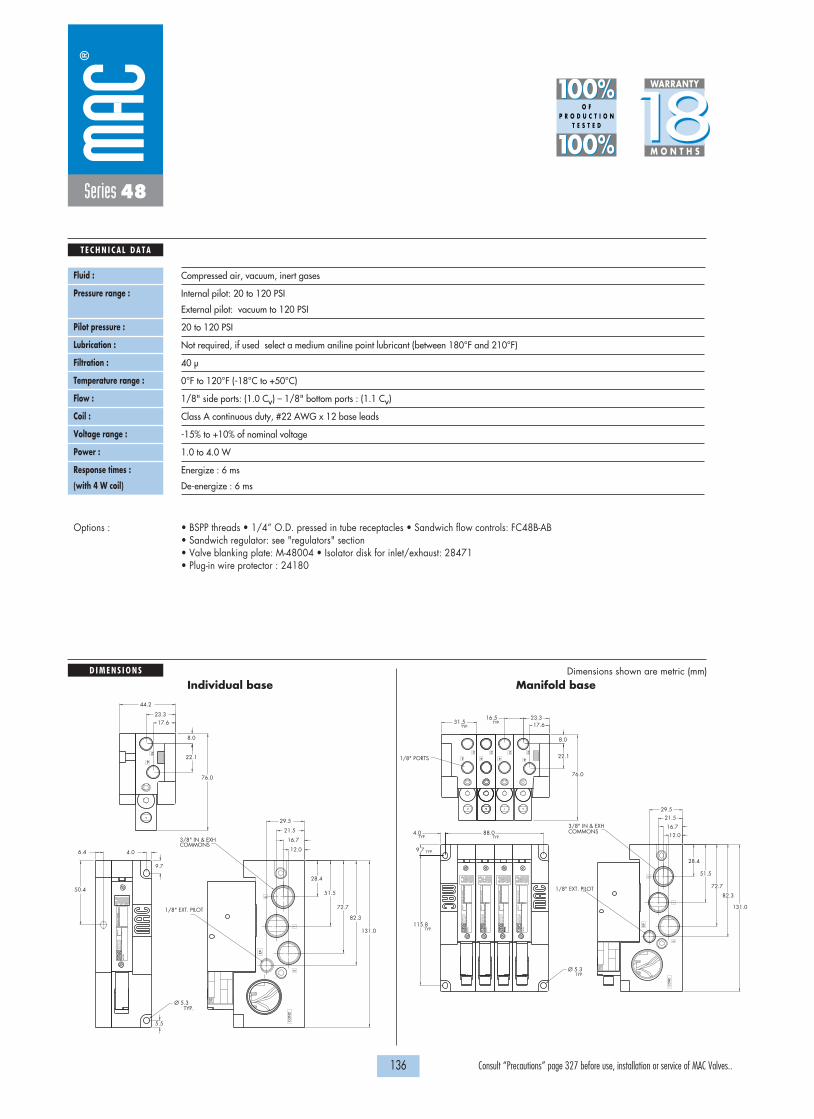
1818100%100%
100%100% M O N T H S
WARRANTY
O FP R O D U C T I O N
T E S T E D
D I M E N S I O N S
T E C H N I C A L D A T A
Dimensions shown are metric (mm)
136 Consult “Precautions” page 327 before use, installation or service of MAC Valves..
TYP.Ø 5.3
COMMONS3/8" IN & EXH
131.0
82.3
72.7
51.5
28.4
29.5
21.5
16.7
12.0
1/8" EXT. PILOT
6.4 4.0
50.4
9.7
5.5
CO
ND
EP
1
5
3
MO
DE
L
AU
CK
LAN
D, N
.Z.
LIE
GE
, BE
LGIU
MW
IXO
M, M
I. U
SA
MO
DIF
.V
AC
TO
150
PS
I
1/8" EXT. PILOT
1/8" PORTS
VA
C T
O 1
50 P
SI
MO
DIF
.
AU
CK
LAN
D, N
.Z.
LIE
GE
, BE
LGIU
MW
IXO
M, M
I. U
SA
MO
DE
L
2
4 4
2
17.623.316.5
31.5
8.0
22.1
4.0 88.0TYP.
76.0
9.7
115.8
TYP.
TYP.
TYP.
TYP.TYP.
12.016.7
21.529.5
28.4
51.5
72.7
82.3
131.0
COMMONS3/8" IN & EXH
Ø 5.3TYP.
MO
DE
L
AU
CK
LAN
D, N
.Z.
LIE
GE
, BE
LGIU
MW
IXO
M, M
I. U
SA
MO
DIF
.V
AC
TO
150
PS
I
VA
C T
O 1
50 P
SI
MO
DIF
.
AU
CK
LAN
D, N
.Z.
LIE
GE
, BE
LGIU
MW
IXO
M, M
I. U
SA
MO
DE
L
3
5
1
EP
CO
ND
2 2
44
MO
DE
L
AU
CK
LAN
D, N
.Z.
LIE
GE
, BE
LGIU
MW
IXO
M, M
I. U
SA
MO
DIF
.V
AC
TO
150
PS
I
76.0
22.1
8.0
23.317.6
44.2
4
2
Series 48
Fluid :
Pressure range :
Pilot pressure :
Lubrication :
Filtration :
Temperature range :
Flow :
Coil :
Voltage range :
Power :
Response times :
(with 4 W coil)
Compressed air, vacuum, inert gases
Internal pilot: 20 to 120 PSI
External pilot: vacuum to 120 PSI
20 to 120 PSI
Not required, if used select a medium aniline point lubricant (between 180°F and 210°F)
40 µ
0°F to 120°F (-18°C to +50°C)
1/8" side ports: (1.0 Cv) – 1/8" bottom ports : (1.1 Cv)
Class A continuous duty, #22 AWG x 12 base leads
-15% to +10% of nominal voltage
1.0 to 4.0 W
Energize : 6 ms
De-energize : 6 ms
• BSPP threads • 1/4” O.D. pressed in tube receptacles • Sandwich flow controls: FC48B-AB • Sandwich regulator: see "regulators" section• Valve blanking plate: M-48004 • Isolator disk for inlet/exhaust: 28471• Plug-in wire protector : 24180
Options :
Individual base Manifold base

D i r e c t s o l e n o i d a n d s o l e n o i d p i l o t o p e r a t e d v a l v e s
137 Consult “Precautions” page 327 before use, installation or service of MAC Valves..
36
32
3738
3334
5267
46
44
47
42
400
48
92
93
ISO 1ISO 2 ISO 3
69
48P
ISO 01ISO 02
Series 48
OPTIONS FOR NONPLUG-IN VALVES
48B-XMX-XXX-GXXX-XXX
M Pilot exhaust muffledP Pilot exhaust piped (# 10-32)U Pilot exhaust to main exhaust
48B-XXX-XJX-GXXX-XXX
J Manifold base – Side portsK Manifold base – Bottom portsL Left end manifold base – Side portsM Left end manifold base – Bottom portsN Right end manifold base – Side ports P Right end manifold base – Bottom ports
Base only :
Pilot style :
Manifold base
- Manifold base
Base type :
Individual base
- Individual base
Universal spool
48B-000-XXX (i.e. 48B-000-AAL) 48B-000-XXX (i.e. 48B-000-AJL)
48B-XXX-XAX-GXXX-XXX
A Individual base – Side portsB Individual base – Bottom ports
48B-RXX-XXX-GXXX-XXX
R 2 position single solenoid universal spoolS 2 position double solenoid universal spool
48A-XXX-XAX-LXXX-XXX
A Individual base – Side portsB Individual base – Bottom portsJ Manifold base – Side portsK Manifold base – Bottom portsL Left end manifold base – Side portsM Left end manifold base – Bottom portsN Right end manifold base – Side portsP Right end manifold base – Bottom ports
Base/Manifold configurations for LATCHING SOLENOID VALVES :

D i r e c t s o l e n o i d a n d s o l e n o i d p i l o t o p e r a t e d v a l v e s
138 Consult “Precautions” page 327 before use, installation or service of MAC Valves..
48B-XXJ-XXX-GXXP-XST
J Internal pilot single pressureK Internal pilot dual pressure supply from #3 portL Internal pilot dual pressure supply from #5 portM External pilot
For LED with diode (2 & 3 position double solenoid valves)
48A-XXX-XXA-LXXP-XXX
A Plug-in Int. Pilot – 2 Wire LatchingB Plug-in Ext. Pilot – 2 Wire LatchingC Plug-in Int. Pilot – 3 Wire LatchingD Plug-in Ext. Pilot – 3 Wire LatchingE Plug-in Int. Pilot – 4 Wire LatchingF Plug-in Ext. Pilot – 4 Wire Latching
Base/Manifold options for int./ext. pilot for LATCHING SOLENOID VALVES :
Series 48
OPTIONS FORPLUG-IN VALVES
48B-XMX-XXX-GXXP-XXX
M Pilot exhaust muffledP Pilot exhaust piped (# 10-32)U Pilot exhaust to main exhaust
48B-XXX-XJX-GXXP-XXX
J Manifold base – Side portsK Manifold base – Bottom portsL Left end manifold base – Side portsM Left end manifold base – Bottom portsN Right end manifold base – Side ports P Right end manifold base – Bottom ports
Base only :
Pilot style :
Manifold base
- Manifold base wired for a double solenoid valve
Base type : Individual base
- Individual base wired for a single solenoid valve
Universal spool
48B-000-XXX (i.e. 48B-000-AAA) 48B-000-XXX (i.e. 48B-000-AJC)
48B-XXX-XAX-GXXP-XXX
A Individual base – Side portsB Individual base – Bottom ports
48B-RXX-XXX-GXXP-XXX
R 2 position single solenoid universal spoolS 2 position double solenoid universal spool
48A-XXX-XAX-LXXP-XXX
A Individual base – Side portsB Individual base – Bottom portsJ Manifold base – Side portsK Manifold base – Bottom portsL Left end manifold base – Side portsM Left end manifold base – Bottom portsN Right end manifold base – Side portsP Right end manifold base – Bottom ports
Base/Manifold configurations for LATCHING SOLENOID VALVES :

139 Consult “Precautions” page 327 before use, installation or service of MAC Valves..
Individual mounting Series
D i r e c t s o l e n o i d a n d s o l e n o i d p i l o t o p e r a t e d v a l v e s
SERIES FEATURES
36
32
3738
3334
5267
46
44
47
42
400
48
92
93
ISO 1ISO 2 ISO 3
69
48P
ISO 01ISO 02
Inline Sub-base non “plug-in”
Series 400
• Patented MACSOLENOID® for fastest possible response timesand virtually burn-out proof AC solenoid operation.
• Optional low watt DC solenoids.• Various manual operators.• Optional memory spring.• 2 position or 3 position valve configurations.• Internal or external pilot.
2 4
1 53
Air return
Bonded spool
Manual operator
Solenoid
4-way pilot with balanced poppet

1818100%100%
100%100% M O N T H S
WARRANTY
O FP R O D U C T I O N
T E S T E D
140 Consult “Precautions” page 327 before use, installation or service of MAC Valves..
Series 400
SPOOL CONFIGURATIONS
122 4
513
14
122 4
513
14
122 4
513
14 122 4
513
14
122 4
513
14
122 4
513
14
EXT. PILOT PORTEXTERNAL PILOTINTERNAL PILOT
SINGLE OPERATOR - SINGLE INLETSHOWN WITH 12 OPERATOR ENERGIZED
SINGLE OPERATOR - SINGLE INLETSHOWN WITH 12 OPERATOR ENERGIZED
INTERNAL PILOTINTERNAL PILOT (FROM #5 PORT)
3 POSITION CLOSED CENTERSINGLE OPERATOR - DUAL INLETSHOWN WITH 12 OPERATOR ENERGIZED
INTERNAL PILOTINTERNAL PILOT
3 POSITION PRESSURE CENTER3 POSITION OPEN CENTER

OPERATIONAL BENEFITS
D i r e c t s o l e n o i d a n d s o l e n o i d p i l o t o p e r a t e d v a l v e s
H O W T O O R D E R
141 Consult “Precautions” page 327 before use, installation or service of MAC Valves..
36
32
3738
3334
5267
46
44
47
42
400
48
92
93
ISO 1ISO 2 ISO 3
69
48P
ISO 01ISO 02
Series 400
Function Port size Flow (Max) Individual mounting Series
5/2, 5/3 1/8” - 1/4” 1.0 Cv Inline
1. The 4-way pilot develops maximum shiftingforces both ways.
2. Memory spring available.3. Balanced spool, immune to variations of
pressure, also provides high flow.4. Short stroke with high flow.5. Bonded spool with minimum friction, shifting
in a glass-like finished bore.6. Wiping effect eliminates sticking.7. Long service life.
DM-D XXX-XXX *SOLENOID OPERATOR �
Voltage
JA 110/50, 120/60 (2.9W)JB 220/50, 240/60 (2.9W)JC 24/60 (2.9W)FB 24 VDC (1.8W)DA 24 VDC (5.4W)DF 24 VDC (12.7W)
Wire length
A 18” (Flying leads)B 24” (Flying leads)J Connector
Manual operator
1 Non-locking recessed2 Locking recessed
Electrical connection
KA Square connectorKD Square connector with lightJB Rectangular connectorJD Rectangular connector with
lightBA Flying leads
XX X X XX
* Other options available, see page 309.** Other options available, see page 313.
5/2Single operator
411A-A0A-XX-XXXX-XXX
411A-B0A-XX-XXXX-XXX
411A-A0B-XX-XXXX-XXX
411A-B0B-XX-XXXX-XXX
5/2Double operator
421A-A0A-XX-XXXX-XXX
421A-B0A-XX-XXXX-XXX
421A-A0B-XX-XXXX-XXX
421A-B0B-XX-XXXX-XXX
5/3Closed center
451A-A0A-XX-XXXX-XXX
451A-B0A-XX-XXXX-XXX
451A-A0B-XX-XXXX-XXX
451A-B0B-XX-XXXX-XXX
5/3Open center
461A-A0A-XX-XXXX-XXX
461A-B0A-XX-XXXX-XXX
461A-A0B-XX-XXXX-XXX
461A-B0B-XX-XXXX-XXX
5/3Pressure center
471A-A0A-XX-XXXX-XXX
471A-B0A-XX-XXXX-XXX
471A-A0B-XX-XXXX-XXX
471A-B0B-XX-XXXX-XXX
2 412 14
3 1 5
2 412 14
3 1 5
2 412 14
3 1 5
2 412 14
3 1 5
2 412 14
3 1 5
Port size
1/8” NPTF
1/4” NPTF
1/8” NPTF
1/4” NPTF
Pilot air
Internal
External
SINGLE PRESSURE MODELS
5/2Single operator
431A-A0A-XX-XXXX-XXX
431A-B0A-XX-XXXX-XXX
431A-A0B-XX-XXXX-XXX
431A-B0B-XX-XXXX-XXX
5/2Double operator
441A-A0A-XX-XXXX-XXX
441A-B0A-XX-XXXX-XXX
441A-A0B-XX-XXXX-XXX
441A-B0B-XX-XXXX-XXX
Port size
1/8” NPTF
1/4” NPTF
1/8” NPTF
1/4” NPTF
Pilot air
Internal
External
DUAL PRESSURE MODELS (INTERNAL PILOT – PILOT PRESSURE SUPPLY FROM #5 PORT)
2 412 14
3 1 5
2 412 14
3 1 5
GM-G XXX-XXX **SOLENOID OPERATOR �
Voltage
DC 24VDC (1.8W)DD 24VDC (2.5W)DF 24VDC (4.0W)
Wire length
A 18”B 24”C 36”
Manual operator
1 Non-locking recessed2 Locking recessed
Electrical connection
BA Flying leadsBT Flying leads with lightKA Plug-in wire assy.KT Plug-in wire assy. with light
XX X X XX

21.0
10.5
26.0
5.0
42.7
51.2
43.034.5
18.0 18.0
9.8
137.5
131.0
99.0
4.25 DIA. MTG. HOLES, TYP.(2)
SINGLE PILOTW/ FLYING LEADS (GM)
SINGLE PILOTW/ PLUG-IN (GM)
DOUBLE PILOTW/ FLYING LEADS (GM)
DOUBLE PILOTW/ PLUG-IN (GM)
102.3
PILOT W/ GM SOLENOID
60.2
PILOT W/ DM SOLENOID
62.5
PILOT W/ GM SOLENOID
PILOT W/ DM SOLENOID
PILOT W/ DM SOLENOID
PILOT W/ GM SOLENOID
OPTIONAL MANUALOPERATOR
17.0
44.0
15.5
DOUBLE PILOT (DM)
SIMPLEPILOT (DM)96.0
125.0
22 .0 52.0
43.5
7.8
9.318.7
PILOT W/ DM SOLENOID
PILOT W/ DM SOLENOID
PILOT W/ GM SOLENOID
PILOT W/ GM SOLENOID
39.0
30.5
3.25 DIA. MTG.HOLES, TYP.(2)
513
2 4 7
1818100%100%
100%100% M O N T H S
WARRANTY
O FP R O D U C T I O N
T E S T E D
D I M E N S I O N S
T E C H N I C A L D A T A
Dimensions shown are metric (mm)
142 Consult “Precautions” page 327 before use, installation or service of MAC Valves..
Series 400
Fluid :
Pressure range :
Pilot pressure :
Lubrication :
Filtration :
Temperature range :
Flow :
Coil :
Voltage range :
Protection :
Power :
Response times :
Compressed air, vacuum, inert gases
Internal pilot – 2 pos. : 20 to 120 PSI (with memory spring: 30 to 120 PSI) 3 pos.: 35 to 120 PSI
External pilot : vacuum to 120 PSI
2 position: 20 to 120 PSI (with memory spring: 30 to 120 PSI) 3 position: 35 to 120 PSI
Not required, if used select a medium aniline point lubricant (between 180°F and 210°F)
40 µ
0°F to 120°F (-18°C to +50°C)
1.0 Cv
Class A continuous duty, #22 AWG x 12 leads wires
-15% to +10% of nominal voltage
Consult factory
~Inrush : 10.9 VA Holding : 7.7 VA
= 1.8 to 12.7 W
24 V=/5.4W Energize : 7.3 ms De-energize : 5.3 ms
120/60 Energize : 8-12 ms De-energize : 7-11 ms
• BSPP threads • Namur interface (specify mod. 1080 after model)
• DM pilot body pressure seal: 16542 • DM pilot spacer plate: 24168-01.
Options :
Spare parts :
411A-A0A-XX-XXXX-XXX
Dual pressure models, replace by C for pilot supply from #3 portFor memory spring, replace by 4 (single operator models only)Replace by 8 for 3 position dual pressure, pressure center

OPERATIONAL BENEFITS
D i r e c t s o l e n o i d a n d s o l e n o i d p i l o t o p e r a t e d v a l v e s
H O W T O O R D E R
143 Consult “Precautions” page 327 before use, installation or service of MAC Valves..
36
32
3738
3334
5267
46
44
47
42
400
48
92
93
ISO 1ISO 2 ISO 3
69
48P
ISO 01ISO 02
Series 400
Function Port size Flow (Max) Individual mounting Series
5/2, 5/3 1/8” - 1/4” 1.0 CvSub-base
non “plug-in”
1. The 4-way pilot develops maximum shiftingforces both ways.
2. Memory spring available.3. Balanced spool, immune to variations of
pressure, also provides high flow.4. Short stroke with high flow.5. Bonded spool with minimum friction, shifting
in a glass-like finished bore.6. Wiping effect eliminates sticking.7. Long service life.
DM-D XXX-XXX *SOLENOID OPERATOR �
Voltage
JA 110/50, 120/60 (2.9W)JB 220/50, 240/60 (2.9W)JC 24/60 (2.9W)FB 24 VDC (1.8W)DA 24 VDC (5.4W)DF 24 VDC (12.7W)
Wire length
A 18” (Flying leads)B 24” (Flying leads)J Connector
Manual operator
1 Non-locking recessed2 Locking recessed
Electrical connection
KA Square connectorKD Square connector with lightJB Rectangular connectorJD Rectangular connector with
lightBA Flying leads
XX X X XX
* Other options available, see page 309.** Other options available, see page 313.
5/2 Single operator
413A-00A-XX-XXXX-XXX
413A-00D-XX-XXXX-XXX
413A-AAA-XX-XXXX-XXX
413A-BAA-XX-XXXX-XXX
413A-AAD-XX-XXXX-XXX
413A-BAD-XX-XXXX-XXX
5/2 Double operator
423A-00A-XX-XXXX-XXX
423A-00D-XX-XXXX-XXX
423A-AAA-XX-XXXX-XXX
423A-BAA-XX-XXXX-XXX
423A-AAD-XX-XXXX-XXX
423A-BAD-XX-XXXX-XXX
5/3 Closed center
453A-00A-XX-XXXX-XXX
453A-00D-XX-XXXX-XXX
453A-AAA-XX-XXXX-XXX
453A-BAA-XX-XXXX-XXX
453A-AAD-XX-XXXX-XXX
453A-BAD-XX-XXXX-XXX
5/3 Open center
463A-00A-XX-XXXX-XXX
463A-00D-XX-XXXX-XXX
463A-AAA-XX-XXXX-XXX
463A-BAA-XX-XXXX-XXX
463A-AAD-XX-XXXX-XXX
463A-BAD-XX-XXXX-XXX
5/3 Pressure center
473A-00A-XX-XXXX-XXX
473A-00D-XX-XXXX-XXX
473A-AAA-XX-XXXX-XXX
473A-BAA-XX-XXXX-XXX
473A-AAD-XX-XXXX-XXX
473A-BAD-XX-XXXX-XXX
2 412 14
3 1 5
2 412 14
3 1 5
2 412 14
3 1 5
2 412 14
3 1 5
2 412 14
3 1 5
Port size
Valve only
1/8” NPTF1/4” NPTF1/8” NPTF1/4” NPTF
Pilot air
InternalExternalInternal
External
SINGLE PRESSURE MODELS
5/2 Single operator
433A-00A-XX-XXXX-XXX
433A-00D-XX-XXXX-XXX
433A-AAA-XX-XXXX-XXX
433A-BAA-XX-XXXX-XXX
433A-AAD-XX-XXXX-XXX
433A-BAD-XX-XXXX-XXX
5/2 Double operator
443A-00A-XX-XXXX-XXX
443A-00D-XX-XXXX-XXX
443A-AAA-XX-XXXX-XXX
443A-BAA-XX-XXXX-XXX
443A-AAD-XX-XXXX-XXX
443A-BAD-XX-XXXX-XXX
Port size
Valve only
1/8” NPTF1/4” NPTF1/8” NPTF1/4” NPTF
Pilot air
InternalExternalInternal
External
DUAL PRESSURE MODELS (INTERNAL PILOT – PILOT PRESSURE SUPPLY FROM #5 PORT)
2 412 14
3 1 5
2 412 14
3 1 5
GM-G XXX-XXX **SOLENOID OPERATOR �
Voltage
DC 24VDC (1.8W)DD 24VDC (2.5W)DF 24VDC (4.0W)
Wire length
A 18”B 24”C 36”
Manual operator
1 Non-locking recessed2 Locking recessed
Electrical connection
BA Flying leadsBT Flying leads with lightKA Plug-in wire assy.KT Plug-in wire assy. with light
XX X X XX

1818100%100%
100%100% M O N T H S
WARRANTY
O FP R O D U C T I O N
T E S T E D
D I M E N S I O N S
T E C H N I C A L D A T A
Dimensions shown are metric (mm)
144 Consult “Precautions” page 327 before use, installation or service of MAC Valves..
MIG. HOLES4.30 DIA. (2)
TYPICAL1/4" - 18 N.P.T.F.1/8" - 27 N.P.T.F.
CONTROLFLOWOPTIONAL
513
42
12 14
25 TO 120 PSI
CL
2 4
CL
12 14 10.0
31.0
62.0
9.5 REF.
STOCK REF. 19.05
OPERATOREXTENDED 86.2
OPERATORLOCKNING 97.9
31.0 20.0
SINGLE PILOT 108.5
81.4
5.0 47.00
28.1038.1 33.1
DOUBLE PILOT 125.0
11.9
PILOT PORT (#10-32 UNF-28)OPTIONAL EXTERNAL
26.5
Series 400
Fluid :
Pressure range :
Pilot pressure :
Lubrication :
Filtration :
Temperature range :
Flow :
Coil :
Voltage range :
Protection :
Power :
Response times :
Compressed air, vacuum, inert gases
Internal pilot – 2 pos. : 20 to 120 PSI (with memory spring: 30 to 120 PSI) 3 pos.: 35 to 120 PSI
External pilot : vacuum to 120 PSI
2 position: 20 to 120 PSI (with memory spring: 30 to 120 PSI) 3 position: 35 to 120 PSI
Not required, if used select a medium aniline point lubricant (between 180°F and 210°F)
40 µ
0°F to 120°F (-18°C to +50°C)
1.0 Cv
Class A continuous duty, #22 AWG x 12 leads wires
-15% to +10% of nominal voltage
Consult factory
~Inrush : 10.9 VA Holding : 7.7 VA
= 1.8 to 12.7 W
24 V=/5.4W Energize : 7.3 ms De-energize : 5.3 ms
120/60 Energize : 8-12 ms De-energize : 7-11 ms
• BSPP threads
• Body to base seal: 16525 • Flow control assembly: N-04001 • Body mounting screws (x2): 35043.
Options :
Spare parts :
400A-XXX(i.e. 400A-AAA)
Base only :413A-AAA-XX-XXXX-XXX
Dual pressure models, replace by C for pilot supply from #3 portFor flow control, replace by BFor memory spring, replace by 6

145 Consult “Precautions” page 327 before use, installation or service of MAC Valves..
Individual mounting Series
D i r e c t s o l e n o i d a n d s o l e n o i d p i l o t o p e r a t e d v a l v e s
SERIES FEATURES
36
32
3738
3334
5267
46
44
47
42
400
48
92
93
ISO 1ISO 2 ISO 3
69
48P
ISO 01ISO 02
Sub-base non “plug-in”
Sub-base “plug-in”
Sub-base “plug-in”
Sub-base non “plug-in”
Series 92
Manifold mounting
• Patented MACSOLENOID® for fastest possible response timesand virtually burn-out proof AC solenoid operation.
• Optional low watt DC solenoids.• Optional memory spring.• Plug-in design of valves and bases for ease of maintenance.• 2 position or 3 position valve configurations.
EXH. EXH.
EXH.
IN.
IN. AB
Bonded spool
Optional lightManual operator
Solenoid
Plug-in solenoid
4-way pilot with balanced poppet
Air return

1818100%100%
100%100% M O N T H S
WARRANTY
O FP R O D U C T I O N
T E S T E D
146 Consult “Precautions” page 327 before use, installation or service of MAC Valves..
Series 92
SPOOL CONFIGURATIONS
REGULATOR CONFIGURATIONS
MANIFOLD WITH REGULATOR - SINGLE PRESSURE MANIFOLD WITH REGULATOR - DUAL PRESSURE
SINGLE REGULATOR - SINGLE PRESSUREPressure supplied to the individual or manifold base passes through the regulator.Regulated pressure is supplied to the pressure path of the valve.
Note: For both single and dual pressure, air supply to the pilot system is never regulated.
DUAL REGULATOR - DUAL PRESSUREPressure supplied from each regulator is divided in the block.Regulated pressure from “A” regulator supplies cylinder port “A”.Regulated pressure from “B” regulator supplies cylinder port “B”.Dual pressure regulators require dual pressure spool in valve.
B A
EXHAINBEXH
2 POSITION SINGLE PRESSURESHOWN WITH "B" OPERATOR ENERGIZED
B A
INAEXHBIN
2 POSITION DUAL PRESSURESHOWN WITH "B" OPERATOR ENERGIZED
B A
EXHAINBEXH
A
EXHAINBEXH
3 POSITION OPEN CENTER
3 POSITION SINGLE PRESSURE, PRESSURE CENTER
B A
EXHAINBEXH
3 POSITION CLOSED CENTERSPRING CENTERING
EXH. EXH.IN. AB INEXH. ABIN

OPERATIONAL BENEFITS
D i r e c t s o l e n o i d a n d s o l e n o i d p i l o t o p e r a t e d v a l v e s
H O W T O O R D E R
147 Consult “Precautions” page 327 before use, installation or service of MAC Valves..
36
32
3738
3334
5267
46
44
47
42
400
48
92
93
ISO 1ISO 2 ISO 3
69
48P
ISO 01ISO 02
Series 92
Function Port size Flow (Max) Individual mounting Series
5/2, 5/3 1/8” - 1/4” - 3/8” 1.2 CvSub-base
non “plug-in”
1. The 4-way pilot develops maximum shiftingforces both ways.
2. Memory spring available.3. Balanced spool, immune to variations of
pressure, also provides high flow.4. Short stroke with high flow.5. Bonded seal spool with minimum friction,
shifting in a glass-like finished bore.6. Pilot with balanced poppet, high flow; short
and consistent response times.
DM-D XXX-XXX *SOLENOID OPERATOR �
Voltage
JA 110 /50, 120/60 (2.9W)JB 220/50, 240/60 (2.9W)JC 24/60 (2.9W)FB 24 VDC (1.8W)DA 24 VDC (5.4W)DF 24 VDC (12.7W)
Wire length
A 18” (Flying leads)B 24” (Flying leads)J Connector
Manual operator
1 Non-locking recessed2 Locking recessed
Electrical connection
BM Flying leadsBN Flying leads with diodeBP Flying leads with M.O.V.BG Flying leads with groundJB Rectangular connector JD Rectangular connector with lightKA Square connector
XX X X XX
* Other options available, see page 309.Other options available for the 92 series valves, see page 155.
5/2Single operator
92B-ABA-000-DM-DXXX-XXX
92B-ABA-AAG-DM-DXXX-XXX
92B-ABA-BAG-DM-DXXX-XXX
92B-ABA-CAG-DM-DXXX-XXX
92B-ABA-AAH-DM-DXXX-XXX
92B-ABA-BAH-DM-DXXX-XXX
92B-ABA-CAH-DM-DXXX-XXX
5/2Double operator
92B-BBA-000-DM-DXXX-XXX
92B-BBA-AAG-DM-DXXX-XXX
92B-BBA-BAG-DM-DXXX-XXX
92B-BBA-CAG-DM-DXXX-XXX
92B-BBA-AAH-DM-DXXX-XXX
92B-BBA-BAH-DM-DXXX-XXX
92B-BBA-CAH-DM-DXXX-XXX
5/3Closed center
92B-EBA-000-DM-DXXX-XXX
92B-EBA-AAG-DM-DXXX-XXX
92B-EBA-BAG-DM-DXXX-XXX
92B-EBA-CAG-DM-DXXX-XXX
92B-EBA-AAH-DM-DXXX-XXX
92B-EBA-BAH-DM-DXXX-XXX
92B-EBA-CAH-DM-DXXX-XXX
5/3Open center
92B-FBA-000-DM-DXXX-XXX
92B-FBA-AAG-DM-DXXX-XXX
92B-FBA-BAG-DM-DXXX-XXX
92B-FBA-CAG-DM-DXXX-XXX
92B-FBA-AAH-DM-DXXX-XXX
92B-FBA-BAH-DM-DXXX-XXX
92B-FBA-CAH-DM-DXXX-XXX
5/3Pressure center
92B-GBA-000-DM-DXXX-XXX
92B-GBA-AAG-DM-DXXX-XXX
92B-GBA-BAG-DM-DXXX-XXX
92B-GBA-CAG-DM-DXXX-XXX
92B-GBA-AAH-DM-DXXX-XXX
92B-GBA-BAH-DM-DXXX-XXX
92B-GBA-CAH-DM-DXXX-XXX
Port size
Valve less base
1/8” NPTF
1/4” NPTF
3/8” NPTF
1/8” NPTF
1/4” NPTF
3/8” NPTF
Pilot air
Internal
External
SINGLE PRESSURE MODELS
5/2Single operator
92B-CBA-000-DM-DXXX-XXX
92B-CBA-AAG-DM-DXXX-XXX
92B-CBA-BAG-DM-DXXX-XXX
92B-CBA-CAG-DM-DXXX-XXX
92B-CBA-AAH-DM-DXXX-XXX
92B-CBA-BAH-DM-DXXX-XXX
92B-CBA-CAH-DM-DXXX-XXX
5/2Double operator
92B-DBA-000-DM-DXXX-XXX
92B-DBA-AAG-DM-DXXX-XXX
92B-DBA-BAG-DM-DXXX-XXX
92B-DBA-CAG-DM-DXXX-XXX
92B-DBA-AAH-DM-DXXX-XXX
92B-DBA-BAH-DM-DXXX-XXX
92B-DBA-CAH-DM-DXXX-XXX
Port size
Valve less base
1/8” NPTF
1/4” NPTF
3/8” NPTF
1/8” NPTF
1/4” NPTF
3/8” NPTF
Pilot air
Internal
External
DUAL PRESSURE MODELS (REQUIRE SANDWICH REGULATOR – SEE "REGULATORS" SECTION)
Above models are shown with side ports.

1818100%100%
100%100% M O N T H S
WARRANTY
O FP R O D U C T I O N
T E S T E D
D I M E N S I O N S
T E C H N I C A L D A T A
Dimensions shown are metric (mm)
148 Consult “Precautions” page 327 before use, installation or service of MAC Valves..
Series 92
Fluid :
Pressure range :
Lubrication :
Filtration :
Temperature range :
Flow :
Coil :
Voltage range :
Protection :
Power :
Response times :
Compressed air, vacuum, inert gases
Internal pilot : 20 to 120 PSI 3 position : 35 to 120 PSI
External pilot : vacuum to 120 PSI 3 position : 35 to 120 PSI
Not required, if used select a medium aniline point lubricant (between 180°F and 210°F)
40 µ
0°F to 120°F (-18°C to +50°C)
1/8": (1.0 Cv) – 1/4": (1.1 Cv) – 3/8": (1.2 Cv)
Class A continuous duty, #22 AWG x 18 lead wire
-15% to +10% of nominal voltage
Consult factory
~Inrush 7.6 VA Holding : 4.8 VA
= 1.8 to 12.7 W
24V=/5.4W Energize : 8 ms De-energize : 7 ms
120/60 Energize : 7-13 ms De-energize : 12-20 ms
• BSPP threads • Sandwich flow control: FC92B-CA
• Pilot valve DM-Dxxx-xxx • Valve blanking plate: M-92002• Pressure seal between valve and base : 16543. • Mounting screws valve to base (X2) : 35050.
Options :
Spare parts :
97,5
23.0TYP.
6.0
20.040.0
9.021.0
55.6
33.3 15.0 4.0
16.032.0
76.0
9.5
31.0
4.0
43.8
24.5
84.5F
E
G 14.5
145.3115.8
B A
C
D
1/8" external pilot port
Double operator
Single operator
1/2" NPSM conduit connection
4.25 dia.Mtg Holes
DIM.
1/8"
1/4"
3/8"
A
12.5
12.5
12.0
B
18.0
18.0
17.0
C
31.0
31.0
30.0
D
54.0
54.0
54.0
E
23.5
23.5
23.5
F
46.5
46.5
47.5
G
18.0
18.0
17.0

OPERATIONAL BENEFITS
D i r e c t s o l e n o i d a n d s o l e n o i d p i l o t o p e r a t e d v a l v e s
H O W T O O R D E R
149 Consult “Precautions” page 327 before use, installation or service of MAC Valves..
36
32
3738
3334
5267
46
44
47
42
400
48
92
93
ISO 1ISO 2 ISO 3
69
48P
ISO 01ISO 02
Series 92
Function Port size Flow (Max) Individual mounting Series
5/2, 5/3 1/8” - 1/4” - 3/8” 1.2 CvSub-base “plug-in”
1. The 4-way pilot develops maximum shiftingforces both ways.
2. Memory spring available.3. Balanced spool, immune to variations of
pressure, also provides high flow.4. Short stroke with high flow.5. Bonded seal spool with minimum friction,
shifting in a glass-like finished bore.6. Pilot with balanced poppet, high flow; short
and consistent response times.
* Other options available, see page 309.Note: Ground required for 30 Volts or higher.Other options available for the 92 series valves, see page 156.
5/2Single operator
92B-AAA-000-DM-DXXP-XXX
92B-AAA-AAA-DM-DXXP-XXX
92B-AAA-BAA-DM-DXXP-XXX
92B-AAA-CAA-DM-DXXP-XXX
92B-AAA-AAD-DM-DXXP-XXX
92B-AAA-BAD-DM-DXXP-XXX
92B-AAA-CAD-DM-DXXP-XXX
5/2Double operator
92B-BAA-000-DM-DXXP-XXX
92B-BAA-AAA-DM-DXXP-XXX
92B-BAA-BAA-DM-DXXP-XXX
92B-BAA-CAA-DM-DXXP-XXX
92B-BAA-AAD-DM-DXXP-XXX
92B-BAA-BAD-DM-DXXP-XXX
92B-BAA-CAD-DM-DXXP-XXX
5/3Closed center
92B-EAA-000-DM-DXXP-XXX
92B-EAA-AAA-DM-DXXP-XXX
92B-EAA-BAA-DM-DXXP-XXX
92B-EAA-CAA-DM-DXXP-XXX
92B-EAA-AAD-DM-DXXP-XXX
92B-EAA-BAD-DM-DXXP-XXX
92B-EAA-CAD-DM-DXXP-XXX
5/3Open center
92B-FAA-000-DM-DXXP-XXX
92B-FAA-AAA-DM-DXXP-XXX
92B-FAA-BAA-DM-DXXP-XXX
92B-FAA-CAA-DM-DXXP-XXX
92B-FAA-AAD-DM-DXXP-XXX
92B-FAA-BAD-DM-DXXP-XXX
92B-FAA-CAD-DM-DXXP-XXX
5/3Pressure center
92B-GAA-000-DM-DXXP-XXX
92B-GAA-AAA-DM-DXXP-XXX
92B-GAA-BAA-DM-DXXP-XXX
92B-GAA-CAA-DM-DXXP-XXX
92B-GAA-AAD-DM-DXXP-XXX
92B-GAA-BAD-DM-DXXP-XXX
92B-GAA-CAD-DM-DXXP-XXX
Port size
Valve less base
1/8”
1/4”
3/8”
1/8”
1/4”
3/8”
Pilot air
Internal
External
SINGLE PRESSURE MODELS
5/2Single operator
92B-CAA-000-DM-DXXP-XXX
92B-CAA-AAA-DM-DXXP-XXX
92B-CAA-BAA-DM-DXXP-XXX
92B-CAA-CAA-DM-DXXP-XXX
92B-CAA-AAD-DM-DXXP-XXX
92B-CAA-BAD-DM-DXXP-XXX
92B-CAA-CAD-DM-DXXP-XXX
5/2Double operator
92B-DAA-000-DM-DXXP-XXX
92B-DAA-AAA-DM-DXXP-XXX
92B-DAA-BAA-DM-DXXP-XXX
92B-DAA-CAA-DM-DXXP-XXX
92B-DAA-AAD-DM-DXXP-XXX
92B-DAA-BAD-DM-DXXP-XXX
92B-DAA-CAD-DM-DXXP-XXX
Port size
Valve less base
1/8”
1/4”
3/8”
1/8”
1/4”
3/8”
Pilot air
Internal
External
DUAL PRESSURE MODELS (REQUIRE SANDWICH REGULATOR – SEE "REGULATORS" SECTION)
Above models are shown with side ports.
Voltage
JA 110 /50, 120/60 (2.9W)JB 220/50, 240/60 (2.9W)JC 24/60 (2.9W)FB 24 VDC (1.8W)DA 24 VDC (5.4W)DF 24 VDC (12.7W)
Manual operator
1 Non-locking recessed2 Locking recessed
Electrical connection
DM Plug-inDN Plug-in with diodeDP Plug-in with M.O.V.DG Plug-in with groundDJ Plug-in with M.O.V. & ground DH Plug-in with diode & ground
DM-D XX P-XXX *SOLENOID OPERATOR �
XX X XX

1818100%100%
100%100% M O N T H S
WARRANTY
O FP R O D U C T I O N
T E S T E D
D I M E N S I O N S
T E C H N I C A L D A T A
Dimensions shown are metric (mm)
150 Consult “Precautions” page 327 before use, installation or service of MAC Valves..
Series 92
Fluid :
Pressure range :
Lubrication :
Filtration :
Temperature range :
Flow :
Coil :
Voltage range :
Protection :
Power :
Response times :
Compressed air, vacuum, inert gases
Internal pilot : 20 to 120 PSI 3 position : 35 to 120 PSI
External pilot : vacuum to 120 PSI 3 position : 35 to 120 PSI
Not required, if used select a medium aniline point lubricant (between 180°F and 210°F)
40 µ
0°F to 120°F (-18°C to +50°C)
1/8": (1.0 Cv) – 1/4": (1.1 Cv) – 3/8": (1.2 Cv)
Class A continuous duty, #22 AWG x 18 lead wire
-15% to +10% of nominal voltage
Consult factory
~Inrush 7.6 VA Holding : 4.8 VA
= 1.8 to 12.7 W
24V=/5.4W Energize : 8 ms De-energize : 7 ms
120/60 Energize : 7-13 ms De-energize : 12-20 ms
• BSPP threads • Sandwich flow control: FC92B-AA (sgl. operator), FC92B-BA (dbl. operator)
• Pilot valve DM-DxxP-xxx • Valve blanking plate: M-92002• Pressure seal between valve and base : 16543. • Mounting screws valve to base (X2) : 35050.
Options :
Spare parts :
97,5
23.0TYP.
6.0
20.040.0
9.021.0
55.6
33.3 15.0 4.0
16.032.0
76.0
9.5
31.0
4.0
43.8
24.5
84.5F
E
G 14.5
4.9
145.3115.3
B A
C
D
DIM.
1/8"
1/4"
3/8"
A
12.5
12.5
12.0
B
18.0
18.0
17.0
C
31.0
31.0
30.0
D
54.0
54.0
54.0
E
23.5
23.5
23.5
F
46.5
46.5
47.5
G
18.0
18.0
17.0
1/8" external pilot port
Double operator
Single operator
1/2" NPSM conduit connection
4.25 dia.Mtg Holes

OPERATIONAL BENEFITS
D i r e c t s o l e n o i d a n d s o l e n o i d p i l o t o p e r a t e d v a l v e s
H O W T O O R D E R
151 Consult “Precautions” page 327 before use, installation or service of MAC Valves..
36
32
3738
3334
5267
46
44
47
42
400
48
92
93
ISO 1ISO 2 ISO 3
69
48P
ISO 01ISO 02
Series 92
Function Port size Flow (Max) Manifold mounting Series
5/2, 5/3 1/4” - 3/8” 1.2 CvSub-base
non “plug-in”
1. The 4-way pilot develops maximum shiftingforces both ways.
2. Memory spring available.3. Balanced spool, immune to variations of
pressure, also provides high flow.4. Short stroke with high flow.5. Bonded seal spool with minimum friction,
shifting in a glass-like finished bore.6. Pilot with balanced poppet, high flow; short
and consistent response times.7. Wiping effect eliminates sticking.8. Long service life.
DM-D XXX-XXX *SOLENOID OPERATOR �
Voltage
JA 110 /50, 120/60 (2.9W)JB 220/50, 240/60 (2.9W)JC 24/60 (2.9W)FB 24 VDC (1.8W)DA 24 VDC (5.4W)DF 24 VDC (12.7W)
Wire length
A 18” (flying leads)J Connector
Manual operator
1 Non-locking recessed2 Locking recessed
Electrical connection
KA Square connectorKD Square connector with lightJB Rectangular connectorJD Rect. connector with lightBA Flying leadsBK Flying leads with diode
XX X X XX
* Other options available, see page 309.End plate kit required (port size 3/8"): M-92004-01-01 (internal pilot)
M-92004-02-01 (External pilot)Other options available for the 92 series valves, see page 155.
5/2Single operator
92B-ABA-000-DM-DXXX-XXX
92B-ABA-BJG-DM-DXXX-XXX
92B-ABA-CJG-DM-DXXX-XXX
5/2Double operator
92B-BBA-000-DM-DXXX-XXX
92B-BBA-BJG-DM-DXXX-XXX
92B-BBA-CJG-DM-DXXX-XXX
5/3Closed center
92B-EBA-000-DM-DXXX-XXX
92B-EBA-BJG-DM-DXXX-XXX
92B-EBA-CJG-DM-DXXX-XXX
5/3Open center
92B-FBA-000-DM-DXXX-XXX
92B-FBA-BJG-DM-DXXX-XXX
92B-FBA-CJG-DM-DXXX-XXX
5/3Pressure center
92B-GBA-000-DM-DXXX-XXX
92B-GBA-BJG-DM-DXXX-XXX
92B-GBA-CJG-DM-DXXX-XXX
Port size
Valve less base
1/4” NPTF
3/8” NPTF
Pilot air
Internal
SINGLE PRESSURE MODELS
5/2Single operator
92B-CBA-000-DM-DXXX-XXX
92B-CBA-BJG-DM-DXXX-XXX
92B-CBA-CJG-DM-DXXX-XXX
5/2Double operator
92B-DBA-000-DM-DXXX-XXX
92B-DBA-BJG-DM-DXXX-XXX
92B-DBA-CJG-DM-DXXX-XXX
Port size
Valve less base
1/4” NPTF
3/8” NPTF
Pilot air
Internal
DUAL PRESSURE MODELS (REQUIRE SANDWICH REGULATOR – SEE "REGULATORS" SECTION)
Above models are shown with side ports.

14.0
148.3
115.573.1
51.227.0
25.5
25.642.0
36.525.5
21.5
118.7
33.0
11.0
28.5
26.5
Ø 6.387.0
5.5
15.0 22.025.0
9.0
A
B
VAC
TO X
XX P
SI
MO
DIF
.
AUCK
LAND
,N.Z
.LI
EGE,
BELG
IUM
WIX
OM
,MI.U
SA
MO
DEL
MO
DEL
AUCK
LAND
,N.Z
.LI
EGE,
BELG
IUM
WIX
OM
,MI.U
SAM
OD
IF.
VAC
TO X
XX P
SI
B
A
A
B B
A
B
A
EXT.P
COND
EA
INEB
AUCKLAND,N.Z.LIEGE,BELGIUMWIXOM,MI. USA MODIF.
MODEL
ELECTRICAL WATTS
VAC TO 120 PSI
MO
DEL
AUCK
LAND
,N.Z
.LI
EGE,
BELG
IUM
WIX
OM
,MI.U
SAM
OD
IF.
VAC
TO X
XX P
SI
B
A
1818100 %100 %
100 %100 % M O N T H S
WARRANTY
O FP R O D U C T I O N
T E S T E D
DIMENSIONS
TECHNICAL DATA
Dimensions shown are metric (mm)
152 Consult “Precautions” page 327 before use, installation or service of MAC Valves..
Series 92
Fluid :
Pressure range :
Lubrication :
Filtration :
Temperature range :
Flow :
Coil :
Voltage range :
Protection :
Power :
Response times :
Compressed air, vacuum, inert gases
Internal pilot : 20 to 120 PSI 3 position : 35 to 120 PSI
External pilot : vacuum to 120 PSI 3 position : 35 to 120 PSI
Not required, if used select a medium aniline point lubricant (between 180°F and 210°F)
40 µ
0°F to 120°F (-18°C to +50°C)
1/4": (1.1 Cv ) – 3/8": (1.2 Cv )
Class A continuous duty, #22 AWG x 18 leads
-15% to +10% of nominal voltage
Consult factory
~Inrush 7.6 VA Holding : 4.8 VA
= 1.8 to 12.7 W
24V=/5.4W Energize : 8 ms De-energize : 7 ms
120/60 Energize : 7-13 ms De-energize : 12-20 ms
• BSPP threads • Sandwich �ow controls: FC92B-CA
• Pilot valve: DM-Dxxx-xxx • Valve blanking plate: M-92002 • Pressure seal, valve to base 16543• Inlet/Exhaust isolator disc: N-92018.
Options :
Spare parts :

OPERATIONAL BENEFITS
D i r e c t s o l e n o i d a n d s o l e n o i d p i l o t o p e r a t e d v a l v e s
H O W T O O R D E R
153
36
32
3738
3334
5267
46
44
47
42
400
48
92
93
ISO 1ISO 2 ISO 3
69
48P
ISO 01ISO 02
Consult “Precautions” page 327 before use, installation or service of MAC Valves..
Series 92
Function Port size Flow (Max) Manifold mounting Series
5/2, 5/3 1/4” - 3/8” 1.2 CvSub-base “plug-in”
1. The 4-way pilot develops maximum shiftingforces both ways.
2. Memory spring available.3. Balanced spool, immune to variations of
pressure, also provides high flow.4. Short stroke with high flow.5. Bonded seal spool with minimum friction,
shifting in a glass-like finished bore.6. Pilot with balanced poppet, high flow; short
and consistent response times.7. Wiping effect eliminates sticking.8. Long service life.
* Other options available, see page 309.Note: Ground required for 30 Volts or higher.End plate kit required (port size 3/8"): M-92004-01-01 (internal pilot)
M-92004-02-01 (external pilot)Other options available for the 92 series valves, see page 156.
5/2Single operator
92B-AAA-000-DM-DXXP-XXX
92B-AAA-BJA-DM-DXXP-XXX
92B-AAA-CJA-DM-DXXP-XXX
5/2Double operator
92B-BAA-000-DM-DXXP-XXX
92B-BAA-BJA-DM-DXXP-XXX
92B-BAA-CJA-DM-DXXP-XXX
5/3Closed center
92B-EAA-000-DM-DXXP-XXX
92B-EAA-BJA-DM-DXXP-XXX
92B-EAA-CJA-DM-DXXP-XXX
5/3Open center
92B-FAA-000-DM-DXXP-XXX
92B-FAA-BJA-DM-DXXP-XXX
92B-FAA-CJA-DM-DXXP-XXX
5/3Pressure center
92B-GAA-000-DM-DXXP-XXX
92B-GAA-BJA-DM-DXXP-XXX
92B-GAA-CJA-DM-DXXP-XXX
Port size
Valve less base
1/4” NPTF
3/8” NPTF
Pilot air
Internal
SINGLE PRESSURE MODELS
5/2Single operator
92B-CAA-000-DM-DXXP-XXX
92B-CAA-BJA-DM-DXXP-XXX
92B-CAA-CJA-DM-DXXP-XXX
5/2Double operator
92B-DAA-000-DM-DXXP-XXX
92B-DAA-BJA-DM-DXXP-XXX
92B-DAA-CJA-DM-DXXP-XXX
Port size
Valve less base
1/4” NPTF
3/8” NPTF
Pilot air
Internal
DUAL PRESSURE MODELS (REQUIRE SANDWICH REGULATOR – SEE "REGULATORS" SECTION)
Above models are shown with side ports and no lights.
Voltage
JA 110 /50, 120/60 (2.9W)JB 220/50, 240/60 (2.9W)JC 24/60 (2.9W)FB 24 VDC (1.8W)DA 24 VDC (5.4W)DF 24 VDC (12.7W)
Manual operator
1 Non-locking recessed2 Locking recessed
Electrical connection
DM Plug-inDN Plug-in with diodeDP Plug-in with M.O.V.DG Plug-in with groundDJ Plug-in with M.O.V. & ground DH Plug-in with diode & ground
DM-D XX P-XXX *SOLENOID OPERATOR �
XX X XX

14.0
148.3
115.573.1
51.227.0
25.5
25.642.0
36.525.5
21.5
118.7
33.0
11.0
28.5
26.5
Ø 6.387.0
5.5
15.0 22.025.0
9.0
A
B
VAC
TO X
XX P
SI
MO
DIF
.
AUCK
LAND
,N.Z
.LI
EGE,
BELG
IUM
WIX
OM
,MI.U
SA
MO
DEL
MO
DEL
AUCK
LAND
,N.Z
.LI
EGE,
BELG
IUM
WIX
OM
,MI.U
SAM
OD
IF.
VAC
TO X
XX P
SI
B
A
A
B B
A
B
A
EXT.P
COND
EA
INEB
AUCKLAND,N.Z.LIEGE,BELGIUMWIXOM,MI. USA MODIF.
MODEL
ELECTRICAL WATTS
VAC TO 120 PSI
MO
DEL
AUCK
LAND
,N.Z
.LI
EGE,
BELG
IUM
WIX
OM
,MI.U
SAM
OD
IF.
VAC
TO X
XX P
SI
B
A
1818100 %100 %
100 %100 % M O N T H S
WARRANTY
O FP R O D U C T I O N
T E S T E D
DIMENSIONS
TECHNICAL DATA
Dimensions shown are metric (mm)
154 Consult “Precautions” page 327 before use, installation or service of MAC Valves..
Series 92
Fluid :
Pressure range :
Lubrication :
Filtration :
Temperature range :
Flow :
Coil :
Voltage range :
Protection :
Power :
Response times :
Compressed air, vacuum, inert gases
Internal pilot : 20 to 120 PSI 3 position : 35 to 120 PSI
External pilot : vacuum to 120 PSI 3 position : 35 to 120 PSI
Not required, if used select a medium aniline point lubricant (between 180°F and 210°F)
40 µ
0°F to 120°F (-18°C to +50°C)
1/4": (1.1 Cv ) – 3/8": (1.2 Cv )
Class A continuous duty, #22 AWG x 12 base leads
-15% to +10% of nominal voltage
Consult factory
~Inrush 7.6 VA Holding : 4.8 VA
= 1.8 to 12.7 W
24V=/5.4W Energize : 8 ms De-energize : 7 ms
120/60 Energize : 7-13 ms De-energize : 12-20 ms
• BSPP threads • Sandwich �ow controls: FC92B-AA (sgl. operator), FC92B-BA (dbl. operator)
• Pilot valve: DM-DxxP-xxx • Valve blanking plate: M-92002 • Pressure seal, valve to base: 16543• Mounting screws valve to base (x2): 35050 • Inlet/Exhaust isolator disc: N-92018.
Options :
Spare parts :

D i r e c t s o l e n o i d a n d s o l e n o i d p i l o t o p e r a t e d v a l v e s
155 Consult “Precautions” page 327 before use, installation or service of MAC Valves..
36
32
3738
3334
5267
46
44
47
42
400
48
92
93
ISO 1ISO 2 ISO 3
69
48P
ISO 01ISO 02
Series 92
OPTIONS FOR NONPLUG-IN VALVES
92B-XXX-XXX-DM-DXXX-XXX
DM pilot exhaust muffledDP pilot exhaust piped (#10-32)DU pilot exhaust to main exhaust
Base only :
* Requires sandwich regulator.** Must use DU pilot. Main valve exhaust cannot be restricted.
Pilot style :
- Manifold base
Valve function
- Individual base
Pilot exhaust
92B-000-XXX (i.e. 92B-000-AAG) 92B-000-XXX (i.e. 92B-000-BJG)
92B-HXX-XXX-XX-DXXX-XXX
H for 3 position dual pressure, pressure center*J for 3 position dual pressure, closed center*K for 3 position dual pressure, open center*L for single operator, single pressure with memory springN for single operator, dual pressure with memory spring*
92B-XXX-XJX-XX-DXXX-XXX
J side portsK bottom ports
Manifold sub-basePort configuration : Individual sub-base
92B-XXX-XAX-XX-DXXX-XXX
A side portsB bottom ports (1/8" only)C side & bottom ports (1/8" only)D side inlet & exhaust with bottom
cylinder ports (1/8")
92B-XBX-XXX-XX-DXXX-XXX
B standard pilot exhaustD pilot exhaust to main valve exhaust**

D i r e c t s o l e n o i d a n d s o l e n o i d p i l o t o p e r a t e d v a l v e s
156 Consult “Precautions” page 327 before use, installation or service of MAC Valves..
Series 92
OPTIONS FORPLUG-IN VALVES
92B-XXX-XXA-XX-DXXP-XXX
A internal pilot no lightB internal pilot single light C internal pilot double light
Individual & Manifold sub-base Int. pilot
92B-XXX-XXD-XX-DXXP-XXX
D external pilot no lightE external pilot single lightF external pilot double light
Individual sub-base Ext. pilot
92B-XXX-XXX-DM-DXXP-XXX
DM pilot exhaust muffledDP pilot exhaust piped (#10-32)DU pilot exhaust to main exhaust
Base only :
* Requires sandwich regulator.** Must use DU pilot. Main valve exhaust cannot be restricted.
(Note: bases are wired for double solenoid valves)
Pilot style :
92B-XXX-XXX-DM-DXXP-XXX
P 12” leads1 18” leads2 24” leads3 36” leads4 48” leads5 72” leads
Lead Wire Lengths : (manifold sub-base only)
- Manifold base
Valve function
- Individual base
Pilot exhaust
92B-000-XXX (i.e. 92B-000-AAA) 92B-000-XXX (i.e. 92B-000-BJA)
92B-HXX-XXX-XX-DXXP-XXX
H for 3 position dual pressure, pressure center*J for 3 position dual pressure, closed center*K for 3 position dual pressure, open center*L for single operator, single pressure with memory springN for single operator, dual pressure with memory spring*
92B-XXX-XJX-XX-DXXP-XXX
J side portsK bottom ports
Manifold sub-basePort configuration : Individual sub-base
92B-XXX-XAX-XX-DXXP-XXX
A side portsB bottom ports (1/8" only)C side & bottom ports (1/8" only)D side inlet & exhaust with bottom
cylinder ports (1/8")
92B-XAX-XXX-XX-DXXP-XXX
A standard pilot exhaustC pilot exhaust to main valve exhaust**
Body electrical
92B-XXA-XXX-XX-DXXP-XXX
A no lightB light(s)F suppression and blocking diode with light(s)H M.O.V. with light(s)
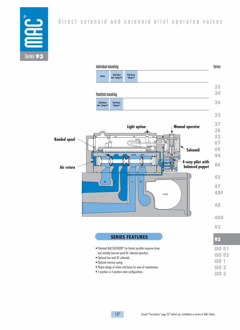
157 Consult “Precautions” page 327 before use, installation or service of MAC Valves..
Individual mounting Series
D i r e c t s o l e n o i d a n d s o l e n o i d p i l o t o p e r a t e d v a l v e s
SERIES FEATURES
36
32
3738
3334
5267
46
44
47
42
400
48
92
93
ISO 1ISO 2 ISO 3
69
48P
ISO 01ISO 02
Inline Sub-base non “plug-in”
Sub-base “plug-in”
Sub-base “plug-in”
Sub-base non “plug-in”
Series 93
Manifold mounting
• Patented MACSOLENOID® for fastest possible response timesand virtually burn-out proof AC solenoid operation.
• Optional low watt DC solenoids.• Optional memory spring.• Plug-in design of valves and bases for ease of maintenance.• 2 position or 3 position valve configurations.
EB B P A EA
COND.
Manual operator
Solenoid
Air return
Light option
Bonded spool
4-way pilot withbalanced poppet

1818100%100%
100%100% M O N T H S
WARRANTY
O FP R O D U C T I O N
T E S T E D
158 Consult “Precautions” page 327 before use, installation or service of MAC Valves..
Series 93
SPOOL CONFIGURATIONS
B A
2 POSITION SINGLE PRESSURESHOWN WITH "B" OPERATOR ENERGIZED
2 POSITION DUAL PRESSURESHOWN WITH "B" OPERATOR ENERGIZED
3 POSITION OPEN CENTER
3 POSITION DUAL PRESSURE, PRESSURE CENTER
3 POSITION CLOSED CENTER
EXH B IN A EXH
B A
EXH B IN A EXH
B A
IN B EXH A IN
B A
EXH B IN A EXH
B A
IN B EXH A IN
SPRING CENTERING
REGULATOR CONFIGURATIONS
MANIFOLD WITH REGULATOR - SINGLE PRESSURE MANIFOLD WITH REGULATOR - DUAL PRESSURE
SINGLE REGULATOR - SINGLE PRESSUREPressure supplied to the individual or manifold base passes through the regulator.Regulated pressure is supplied to the pressure path of the valve.
Note: For both single and dual pressure, air supply to the pilot system is never regulated.
DUAL REGULATOR - DUAL PRESSUREPressure supplied from each regulator is divided in the block.Regulated pressure from “A” regulator supplies cylinder port “A”.Regulated pressure from “B” regulator supplies cylinder port “B”.Dual pressure regulators require dual pressure spool in valve.
EXH. EXH.IN. AB INEXH. ABIN

OPERATIONAL BENEFITS
D i r e c t s o l e n o i d a n d s o l e n o i d p i l o t o p e r a t e d v a l v e s
H O W T O O R D E R
159 Consult “Precautions” page 327 before use, installation or service of MAC Valves..
36
32
3738
3334
5267
46
44
47
42
400
48
92
93
ISO 1ISO 2 ISO 3
69
48P
ISO 01ISO 02
Series 93
Function Port size Flow (Max) Individual mounting Series
5/2, 5/3 3/8” - 1/2” 3.8 Cv Inline
1. Unique patented Macsolenoid® for fastestpossible response times and virtuallyburn-out proof solenoid operation.
2. Balanced poppet 4-way pilot valve providesmaximum shifting forces, preciserepeatability and consistent operation.
3. Air only return. Optional memory spring isalso available.
4. Optional low wattage DC solenoid down to1 watt.
5. MAC spool and bore combination wipesaway contamination, eliminates sticking andallows for use on non-lube service.
DM-D XXX-XXX *SOLENOID OPERATOR �
Voltage
JA 110/50, 120/60JB 220/50, 240/60JC 24/50, 24/60FB 24 VDC (1.8W)DA 24 VDC (5.4W)DF 24 VDC (12.7W)
Wire length
A 18” (Flying leads)B 24” (Flying leads)J Connector
Manual operator
1 Non-locking recessed2 Locking recessed
Electrical connection
KA Square connectorKD Square connector with lightJB Rectangular connectorJD Rectangular connector with lightBA Flying leads
XX X X XX
* Other options available, see page 309.
Other options available for the 93 series valves, see page 169.
O P T I O N S
5/2Single operator
93A-AJ0-B0J-DM-DXXX-XXX
93A-AJ0-C0J-DM-DXXX-XXX
93A-AJ0-B0K-DM-DXXX-XXX
93A-AJ0-C0K-DM-DXXX-XXX
5/2Double operator
93A-BJ0-B0J-DM-DXXX-XXX
93A-BJ0-C0J-DM-DXXX-XXX
93A-BJ0-B0K-DM-DXXX-XXX
93A-BJ0-C0K-DM-DXXX-XXX
5/3Closed center
93A-EJ0-B0J-DM-DXXX-XXX
93A-EJ0-C0J-DM-DXXX-XXX
93A-EJ0-B0K-DM-DXXX-XXX
93A-EJ0-C0K-DM-DXXX-XXX
5/3Open center
93A-FJ0-B0J-DM-DXXX-XXX
93A-FJ0-C0J-DM-DXXX-XXX
93A-FJ0-B0K-DM-DXXX-XXX
93A-FJ0-C0K-DM-DXXX-XXX
Port size
3/8” NPTF
1/2” NPTF
3/8” NPTF
1/2” NPTF
Pilot air
Internal
External
SINGLE PRESSURE MODELS
5/2Single operator
93A-CJ0-B0J-DM-DXXX-XXX
93A-CJ0-C0J-DM-DXXX-XXX
93A-CJ0-B0K-DM-DXXX-XXX
93A-CJ0-C0K-DM-DXXX-XXX
5/2Double operator
93A-DJ0-B0J-DM-DXXX-XXX
93A-DJ0-C0J-DM-DXXX-XXX
93A-DJ0-B0K-DM-DXXX-XXX
93A-DJ0-C0K-DM-DXXX-XXX
5/3Pressure center
93A-HJ0-B0J-DM-DXXX-XXX
93A-HJ0-C0J-DM-DXXX-XXX
93A-HJ0-B0K-DM-DXXX-XXX
93A-HJ0-C0K-DM-DXXX-XXX
Port size
3/8” NPTF
1/2” NPTF
3/8” NPTF
1/2” NPTF
Pilot air
Internal
External
DUAL PRESSURE MODELS
2 412 14
3 1 5
93A-XJX-XXX-DM-DXXX-XXX
J Standard pilot exhaustK Pilot exhaust to main exhaust (use DU pilot)
Pilot exhaust :
122 4 14
3 1 5
122 4 14
3 1 5
12 2 4 14
3 1 5
12 2 4 14
3 1 5
122 4 14
3 1 5
122 4 14
3 1 5

1818100%100%
100%100% M O N T H S
WARRANTY
O FP R O D U C T I O N
T E S T E D
D I M E N S I O N S
T E C H N I C A L D A T A
Dimensions shown are metric (mm)
160 Consult “Precautions” page 327 before use, installation or service of MAC Valves..
24.4 52.1
16.1
40.3
TYP. (2)Ø 6.20
SINGLE SOLENOID
DOUBLE SOLENOID
14
12
EP42P
184.3
155.8
VAC TO 120 PSI
WATTSELECTRICAL
MODELAUCKLAND,N.Z.LIEGE,BELGIUMWIXOM,MI.USA MODIF.
62.9
Series 93
Fluid :
Pressure range :
Lubrication :
Filtration :
Temperature range :
Flow :
Coil :
Voltage range :
Protection :
Power :
Response times :
(with 5.4 W coil)
Compressed air, vacuum, inert gases
Internal Pilot: 20 to 120 PSI
External Pilot: Vacuum to 120 PSI
Not required, if used select a medium aniline point lubricant (between 180°F and 210°F)
40 µ
0°F to 120°F (-18°C to +50°C)
3.8 Cv
Class A continuous duty, #22 AWG x 18 leads
-15% to +10% of nominal voltage
Consult factory
~ Inrush 7.6 VA Holding: 4.8 VA
= 1.8 to 12.7 W
Energize : 13 ms
De-energize : 10 ms
• BSPP threads Option :

OPERATIONAL BENEFITS
D i r e c t s o l e n o i d a n d s o l e n o i d p i l o t o p e r a t e d v a l v e s
H O W T O O R D E R
161 Consult “Precautions” page 327 before use, installation or service of MAC Valves..
36
32
3738
3334
5267
46
44
47
42
400
48
92
93
ISO 1ISO 2 ISO 3
69
48P
ISO 01ISO 02
Series 93
Function Port size Flow (Max) Individual mounting Series
5/2, 5/3 1/4” - 3/8” - 1/2” 3.4 CvSub-base
non “plug-in”
1. Unique patented Macsolenoid® for fastestpossible response times and virtuallyburn-out proof solenoid operation.
2. Balanced poppet 4-way pilot valve providesmaximum shifting forces, preciserepeatability and consistent operation.
3. Air only return. Optional memory spring isalso available.
4. Optional low wattage DC solenoid down to1 watt.
5. MAC spool and bore combination wipesaway contamination, eliminates sticking andallows for use on non-lube service.
DM-D XXX-XXX *SOLENOID OPERATOR �
Voltage
JA 110/50, 120/60JB 220/50, 240/60JC 24/50, 24/60FB 24 VDC (1.8W)DA 24 VDC (5.4W)DF 24 VDC (12.7W)
Wire length
A 18” (Flying leads)B 24” (Flying leads)J Connector
Manual operator
1 Non-locking recessed2 Locking recessed
Electrical connection
BM Flying leadsBN Flying leads with diodeBP Flying leads with M.O.V.BG Flying leads with groundJB Rectangular connector JD Rectangular connector with light
XX X X XX
* Other options available, see page 309.Other options available for the 93 series valves, see page 169.
5/2Single operator
93A-ABA-000-DM-DXXX-XXX
93A-ABA-ABG-DM-DXXX-XXX
93A-ABA-BAG-DM-DXXX-XXX
93A-ABA-CAG-DM-DXXX-XXX
93A-ABA-ABH-DM-DXXX-XXX
93A-ABA-BAH-DM-DXXX-XXX
93A-ABA-CAH-DM-DXXX-XXX
5/2Double operator
93A-BBA-000-DM-DXXX-XXX
93A-BBA-ABG-DM-DXXX-XXX
93A-BBA-BAG-DM-DXXX-XXX
93A-BBA-CAG-DM-DXXX-XXX
93A-BBA-ABH-DM-DXXX-XXX
93A-BBA-BAH-DM-DXXX-XXX
93A-BBA-CAH-DM-DXXX-XXX
5/3Closed center
93A-EBA-000-DM-DXXX-XXX
93A-EBA-ABG-DM-DXXX-XXX
93A-EBA-BAG-DM-DXXX-XXX
93A-EBA-CAG-DM-DXXX-XXX
93A-EBA-ABH-DM-DXXX-XXX
93A-EBA-BAH-DM-DXXX-XXX
93A-EBA-CAH-DM-DXXX-XXX
5/3Open center
93A-FBA-000-DM-DXXX-XXX
93A-FBA-ABG-DM-DXXX-XXX
93A-FBA-BAG-DM-DXXX-XXX
93A-FBA-CAG-DM-DXXX-XXX
93A-FBA-ABH-DM-DXXX-XXX
93A-FBA-BAH-DM-DXXX-XXX
93A-FBA-CAH-DM-DXXX-XXX
Port size
Valve less base
1/4” NPTF
3/8” NPTF
1/2” NPTF
1/4” NPTF
3/8” NPTF
1/2” NPTF
Pilot air
Internal
External
SINGLE PRESSURE MODELS (1/4" MODELS ARE BOTTOM PORTED)
5/2Single operator
93A-CBA-000-DM-DXXX-XXX
93A-CBA-ABG-DM-DXXX-XXX
93A-CBA-BAG-DM-DXXX-XXX
93A-CBA-CAG-DM-DXXX-XXX
93A-CBA-ABH-DM-DXXX-XXX
93A-CBA-BAH-DM-DXXX-XXX
93A-CBA-CAH-DM-DXXX-XXX
5/2Double operator
93A-DBA-000-DM-DXXX-XXX
93A-DBA-ABG-DM-DXXX-XXX
93A-DBA-BAG-DM-DXXX-XXX
93A-DBA-CAG-DM-DXXX-XXX
93A-DBA-ABH-DM-DXXX-XXX
93A-DBA-BAH-DM-DXXX-XXX
93A-DBA-CAH-DM-DXXX-XXX
5/3Pressure center
93A-HBA-000-DM-DXXX-XXX
93A-HBA-ABG-DM-DXXX-XXX
93A-HBA-BAG-DM-DXXX-XXX
93A-HBA-CAG-DM-DXXX-XXX
93A-HBA-ABH-DM-DXXX-XXX
93A-HBA-BAH-DM-DXXX-XXX
93A-HBA-CAH-DM-DXXX-XXX
Port size
Valve less base
1/4” NPTF
3/8” NPTF
1/2” NPTF
1/4” NPTF
3/8” NPTF
1/2” NPTF
Pilot air
Internal
External
DUAL PRESSURE MODELS REQUIRE SANDWICH REGULATOR, SEE „REGULATORS“ SECTION (1/4" MODELS ARE BOTTOM PORTED)
B AB A
EB IN EA

5.85
57.0
28.5
13.0
31.65 36.0A B
E
F
80.0
53.01/8" -27 NPTFEXTERNALPILOT PORT
111.6
H
G
DC
1/2" -14 N.P.S.M.CONDUIT PORT
185.4
156.9
DOUBLE SOLENOID
SINGLE SOLENOID
20.0
6.00
39.1
71.7
96.0
5.3 DIA2 MTG. HOLES
23.0046.00
OPTIONAL BOTTOM PORTS3/8" AND 1/4" ONLY
M L
K JEP
INEX CONDUIT
CYL. BCYL. A
INEX
AB
1818100%100%
100%100% M O N T H S
WARRANTY
O FP R O D U C T I O N
T E S T E D
D I M E N S I O N S
T E C H N I C A L D A T A
Dimensions shown are metric (mm)
162 Consult “Precautions” page 327 before use, installation or service of MAC Valves..
Series 93
Fluid :
Pressure range :
Lubrication :
Filtration :
Temperature range :
Flow :
Coil :
Voltage range :
Protection :
Power :
Response times :
(with 5.4 W coil)
Compressed air, vacuum, inert gases
Internal Pilot: 20 to 120 PSI
External Pilot: Vacuum to 120 PSI
Not required, if used select a medium aniline point lubricant (between 180°F and 210°F)
40 µ
0°F to 120°F (-18°C to +50°C)
1/4”, 3/8” : (3.0 Cv) - 1/2” : (3.4 Cv)
Class A continuous duty, #22 AWG x 18 leads
-15% to +10% of nominal voltage
Consult factory
~ Inrush 7.6 VA Holding: 4.8 VA
= 1 to 12.7 W
Energize : 13 ms
De-energize : 10 ms
• BSPP thread • Sandwich regulator (see ‚regulators‘ section)• Sandwich flow controls FC93A-BA (screwdriver slot adjustment)
FC93A-BB (locking knob adjustment)
• Pilot valve: DM-Dxxx-xxx • Valve to base pressure seal: 16622 • Pilot valve pressure seal: 16542 • Mounting screws valve to base (x4): 35249• Pilot valve mounting screws (x2): 35069
Options :
Spare parts :
DIM.
3/8"1/2"
A
27.1525.5
B
20.6519.0
C
27.1525.5
D
24.1522.5
E
54.145.8
F
81.775.3
G
38.238.2
H
73.573.5
DIM.
1/4"3/8"
J
7.08.5
K
14.716.2
L
15.016.5
M
16.517.5

OPERATIONAL BENEFITS
D i r e c t s o l e n o i d a n d s o l e n o i d p i l o t o p e r a t e d v a l v e s
H O W T O O R D E R
163 Consult “Precautions” page 327 before use, installation or service of MAC Valves..
36
32
3738
3334
5267
46
44
47
42
400
48
92
93
ISO 1ISO 2 ISO 3
69
48P
ISO 01ISO 02
Series 93
Function Port size Flow (Max) Individual mounting Series
5/2, 5/3 1/4” - 3/8” - 1/2” 3.4 CvSub-base “plug-in”
1. Unique patented Macsolenoid® for fastestpossible response times and virtuallyburn-out proof solenoid operation.
2. Balanced poppet 4-way pilot valve providesmaximum shifting forces, preciserepeatability and consistent operation.
3. Air only return. Optional memory spring isalso available.
4. Optional low wattage DC solenoid down to1 watt.
5. MAC spool and bore combination wipesaway contamination, eliminates sticking andallows for use on non-lube service.
* Other options available, see page 309.Note: Ground required for 30 Volts or higher.Other options available for the 93 series valves, see page 170.
5/2Single operator
93A-AAA-000-DM-DXXP-XXX
93A-AAA-ABA-DM-DXXP-XXX
93A-AAA-BAA-DM-DXXP-XXX
93A-AAA-CAA-DM-DXXP-XXX
93A-AAA-ABD-DM-DXXP-XXX
93A-AAA-BAD-DM-DXXP-XXX
93A-AAA-CAD-DM-DXXP-XXX
5/2Double operator
93A-BAA-000-DM-DXXP-XXX
93A-BAA-ABA-DM-DXXP-XXX
93A-BAA-BAA-DM-DXXP-XXX
93A-BAA-CAA-DM-DXXP-XXX
93A-BAA-ABD-DM-DXXP-XXX
93A-BAA-BAD-DM-DXXP-XXX
93A-BAA-CAD-DM-DXXP-XXX
5/3Closed center
93A-EAA-000-DM-DXXP-XXX
93A-EAA-ABA-DM-DXXP-XXX
93A-EAA-BAA-DM-DXXP-XXX
93A-EAA-CAA-DM-DXXP-XXX
93A-EAA-ABD-DM-DXXP-XXX
93A-EAA-BAD-DM-DXXP-XXX
93A-EAA-CAD-DM-DXXP-XXX
5/3Open center
93A-FAA-000-DM-DXXP-XXX
93A-FAA-ABA-DM-DXXP-XXX
93A-FAA-BAA-DM-DXXP-XXX
93A-FAA-CAA-DM-DXXP-XXX
93A-FAA-ABD-DM-DXXP-XXX
93A-FAA-BAD-DM-DXXP-XXX
93A-FAA-CAD-DM-DXXP-XXX
Port size
Valve less base
1/4” NPTF
3/8” NPTF
1/2” NPTF
1/4” NPTF
3/8” NPTF
1/2” NPTF
Pilot air
Internal
External
SINGLE PRESSURE MODELS (1/4" MODELS ARE BOTTOM PORTED)
5/2Single operator
93A-CAA-000-DM-DXXP-XXX
93A-CAA-ABA-DM-DXXP-XXX
93A-CAA-BAA-DM-DXXP-XXX
93A-CAA-CAA-DM-DXXP-XXX
93A-CAA-ABD-DM-DXXP-XXX
93A-CAA-BAD-DM-DXXP-XXX
93A-CAA-CAD-DM-DXXP-XXX
5/2Double operator
93A-DAA-000-DM-DXXP-XXX
93A-DAA-ABA-DM-DXXP-XXX
93A-DAA-BAA-DM-DXXP-XXX
93A-DAA-CAA-DM-DXXP-XXX
93A-DAA-ABD-DM-DXXP-XXX
93A-DAA-BAD-DM-DXXP-XXX
93A-DAA-CAD-DM-DXXP-XXX
5/3Pressure Center
93A-HAA-000-DM-DXXP-XXX
93A-HAA-ABA-DM-DXXP-XXX
93A-HAA-BAA-DM-DXXP-XXX
93A-HAA-CAA-DM-DXXP-XXX
93A-HAA-ABD-DM-DXXP-XXX
93A-HAA-BAD-DM-DXXP-XXX
93A-HAA-CAD-DM-DXXP-XXX
Port size
Valve less base
1/4” NPTF
3/8” NPTF
1/2” NPTF
1/4” NPTF
3/8” NPTF
1/2” NPTF
Pilot air
Internal
External
DUAL PRESSURE MODELS REQUIRE SANDWICH REGULATOR, SEE „REGULATORS“ SECTION (1/4" MODELS ARE BOTTOM PORTED)
B AB A
EB IN EA
Above models are shown without light.
Voltage
JA 110/50, 120/60 (2.9W)JB 220/50, 240/60 (2.9W)JC 24/50, 24/60 (2.9W)FB 24 VDC (1.8W)DA 24 VDC (5.4W)DF 24 VDC (12.7W)
Manual operator
1 Non-locking recessed2 Locking recessed
Electrical connection
DM Plug-inDN Plug-in with diodeDP Plug-in with M.O.V.DG Plug-in with ground
DM-D XX P-XXX *SOLENOID OPERATOR �
XX X XX

5.85
57.0
28.5
13.0
31.65 36.0A B
E
F
80.0
53.01/8" -27 NPTFEXTERNALPILOT PORT
111.6
H
G
DC
1/2" -14 N.P.S.M.CONDUIT PORT
185.4
156.9
DOUBLE SOLENOID
SINGLE SOLENOID
20.0
6.00
39.1
71.7
96.0
5.3 DIA2 MTG. HOLES
23.0046.00
OPTIONAL BOTTOM PORTS3/8" AND 1/4" ONLY
M L
K JEP
INEX CONDUIT
CYL. BCYL. A
INEX
AB
1818100%100%
100%100% M O N T H S
WARRANTY
O FP R O D U C T I O N
T E S T E D
D I M E N S I O N S
T E C H N I C A L D A T A
Dimensions shown are metric (mm)
164 Consult “Precautions” page 327 before use, installation or service of MAC Valves..
Series 93
Fluid :
Pressure range :
Lubrication :
Filtration :
Temperature range :
Flow :
Coil :
Voltage range :
Protection :
Power :
Response times :
(with 5.4 W coil)
Compressed air, vacuum, inert gases
Internal Pilot: 20 to 120 PSI
External Pilot: Vacuum to 120 PSI
Not required, if used select a medium aniline point lubricant (between 180°F and 210°F)
40 µ
0°F to 120°F (-18°C to +50°C)
1/4”, 3/8” : (3.0 Cv) - 1/2” : (3.4 Cv)
Class A continuous duty, #22 AWG x 18 base leads
-15% to +10% of nominal voltage
Consult factory
~ Inrush 7.6 VA Holding: 4.8 VA
= 1 to 12.7 W
Energize : 13 ms
De-energize : 10 ms
• BSPP thread • Sandwich regulator (see ‚regulators‘ section)• Sandwich flow controls FC93A-AA (screwdriver slot adjustment)
FC93A-AB (locking knob adjustment)
• Pilot valve: DM-DxxP-xxx • Valve to base pressure seal: 16622 • Pilot valve pressure seal: 16542 • Mounting screws valve to base (x4): 35249• Pilot valve mounting screws (x2): 35069
Options :
Spare parts :
DIM.
3/8"1/2"
A
27.1525.5
B
20.6519.0
C
27.1525.5
D
24.1522.5
E
54.145.8
F
81.775.3
G
38.238.2
H
73.573.5
DIM.
1/4"3/8"
J
7.08.5
K
14.716.2
L
15.016.5
M
16.517.5

OPERATIONAL BENEFITS
D i r e c t s o l e n o i d a n d s o l e n o i d p i l o t o p e r a t e d v a l v e s
H O W T O O R D E R
165 Consult “Precautions” page 327 before use, installation or service of MAC Valves..
36
32
3738
3334
5267
46
44
47
42
400
48
92
93
ISO 1ISO 2 ISO 3
69
48P
ISO 01ISO 02
Series 93
Function Port size Flow (Max) Manifold mounting Series
5/2, 5/3 3/8” - 1/2” 3.8 CvSub-base
non “plug-in”
1. Unique patented Macsolenoid® for fastestpossible response times and virtuallyburn-out proof solenoid operation.
2. Balanced poppet 4-way pilot valve providesmaximum shifting forces, preciserepeatability and consistent operation.
3. Air only return. Optional memory spring isalso available.
4. Optional low wattage DC solenoid down to1 watt.
5. MAC spool and bore combination wipesaway contamination, eliminates sticking andallows for use on non-lube service.
DM-D XXX-XXX *SOLENOID OPERATOR �
Voltage
JA 110/50, 120/60JB 220/50, 240/60JC 24/50, 24/60FB 24 VDC (1.8W)DA 24 VDC (5.4W)DF 24 VDC (12.7W)
Wire length
A 18” (Flying leads)B 24” (Flying leads)J Connector
Manual operator
1 Non-locking recessed2 Locking recessed
Electrical connection
BM Flying leadsBN Flying leads with diodeKA Square connectorKD Square connector with light
XX X X XX
* Other options available, see page 309.End plate kit required (1/2“ ports): M-93001-01-01 internal pilot.
M-93001-02-01 external pilot.Other options available for the 93 series valves, see page 169.
5/2Single operator
93A-ABA-000-DM-DXXX-XXX
93A-ABA-BJG-DM-DXXX-XXX
93A-ABA-CJG-DM-DXXX-XXX
93A-ABA-BJH-DM-DXXX-XXX
93A-ABA-CJH-DM-DXXX-XXX
5/2Double operator
93A-BBA-000-DM-DXXX-XXX
93A-BBA-BJG-DM-DXXX-XXX
93A-BBA-CJG-DM-DXXX-XXX
93A-BBA-BJH-DM-DXXX-XXX
93A-BBA-CJH-DM-DXXX-XXX
5/3Closed center
93A-EBA-000-DM-DXXX-XXX
93A-EBA-BJG-DM-DXXX-XXX
93A-EBA-CJG-DM-DXXX-XXX
93A-EBA-BJH-DM-DXXX-XXX
93A-EBA-CJH-DM-DXXX-XXX
5/3Open center
93A-FBA-000-DM-DXXX-XXX
93A-FBA-BJG-DM-DXXX-XXX
93A-FBA-CJG-DM-DXXX-XXX
93A-FBA-BJH-DM-DXXX-XXX
93A-FBA-CJH-DM-DXXX-XXX
Port size
Valve less base
3/8” NPTF
1/2” NPTF
3/8” NPTF
1/2” NPTF
Pilot air
Internal
External
SINGLE PRESSURE MODELS
5/2Single operator
93A-CBA-000-DM-DXXX-XXX
93A-CBA-BJG-DM-DXXX-XXX
93A-CBA-CJG-DM-DXXX-XXX
93A-CBA-BJH-DM-DXXX-XXX
93A-CBA-CJH-DM-DXXX-XXX
5/2Double operator
93A-DBA-000-DM-DXXX-XXX
93A-DBA-BJG-DM-DXXX-XXX
93A-DBA-CJG-DM-DXXX-XXX
93A-DBA-BJH-DM-DXXX-XXX
93A-DBA-CJH-DM-DXXX-XXX
5/3Pressure center
93A-HBA-000-DM-DXXX-XXX
93A-HBA-BJG-DM-DXXX-XXX
93A-HBA-CJG-DM-DXXX-XXX
93A-HBA-BJH-DM-DXXX-XXX
93A-HBA-CJH-DM-DXXX-XXX
Port size
Valve less base
3/8” NPTF
1/2” NPTF
3/8” NPTF
1/2” NPTF
Pilot air
Internal
External
DUAL PRESSURE MODELS (REQUIRE SANDWICH REGULATOR, SEE „REGULATORS“ SECTION)
B AB A
EB IN EA
Above models are shown with side ports.

33.015.0
14.6
1/8" N.P.T.F. PILOTPORT 3 PLACES
B
A57.0
TYP.35.5 TYP.
33.0 TYP.
11.5TYP.
27.0 TYP.
39.0 TYP.
70.0 TYP.
105.0 TYP.
143.6 TYP.
1/2" NPTF3HOLESBOTH ENDS
37.5
203.73
182.38
DOUBLE SOLENOID
SINGLE SOLENOID
10.55
19.05
33.519.05
33.5
19.05
10.55 64.70 TYP.22.80
TYP.
OPTIONAL BOTTOMPORTS 3/8" & 1/2"
6.3 DIA4 MTG. HOLES
87.50 TYP.
31.5 TYP.
AA
B
EP EPEP
EBEA
B
IN
EXCONDUIT
AA
1818100%100%
100%100% M O N T H S
WARRANTY
O FP R O D U C T I O N
T E S T E D
D I M E N S I O N S
T E C H N I C A L D A T A
Dimensions shown are metric (mm)
166 Consult “Precautions” page 327 before use, installation or service of MAC Valves..
Series 93
Fluid :
Pressure range :
Lubrication :
Filtration :
Temperature range :
Flow :
Coil :
Voltage range :
Protection :
Power :
Response times :
(with 5.4 W coil)
Compressed air, vacuum, inert gases
Internal Pilot: 20 to 120 PSI
External Pilot: Vacuum to 120 PSI
Not required, if used select a medium aniline point lubricant (between 180°F and 210°F)
40 µ
0°F to 120°F (-18°C to +50°C)
3/8” : (3.4 Cv) - 1/2” : (3.8 Cv)
Class A continuous duty, #22 AWG x 18 leads
-15% to +10% of nominal voltage
Consult factory
~ Inrush 7.6 VA Holding: 4.8 VA
= 1 to 12.7 W
Energize : 13 ms
De-energize : 10 ms
• BSPP thread • Sandwich regulator (see ‚regulators‘ section)• Sandwich flow controls FC93A-BA (screwdriver slot adjustment), FC93A-BB (locking knob adjustment)
• Pilot valve: DM-Dxxx-xxx • Valve to base pressure seal: 16622 • Pilot valve pressure seal: 16542 • Mounting screws valve to base (x4): 35249• Inlet/exh. Isolator disc: N-93008 • Valve blanking plate: M-93002
Options :
Spare parts :
#
B
1
71.6
2
105.1
3
138.6
4
172.1
5
205.6
6
239.1
7
272.6
8
306.1
9
339.6
10
373.1
DIM.
3/8"1/2"
A
47.6649.32

OPERATIONAL BENEFITS
D i r e c t s o l e n o i d a n d s o l e n o i d p i l o t o p e r a t e d v a l v e s
H O W T O O R D E R
167 Consult “Precautions” page 327 before use, installation or service of MAC Valves..
36
32
3738
3334
5267
46
44
47
42
400
48
92
93
ISO 1ISO 2 ISO 3
69
48P
ISO 01ISO 02
Series 93
Function Port size Flow (Max) Manifold mounting Series
5/2, 5/3 3/8” - 1/2” 3.8 CvSub-base “plug-in”
1. Unique patented Macsolenoid® for fastestpossible response times and virtuallyburn-out proof solenoid operation.
2. Balanced poppet 4-way pilot valve providesmaximum shifting forces, preciserepeatability and consistent operation.
3. Air only return. Optional memory spring isalso available.
4. Optional low wattage DC solenoid down to1 watt.
5. MAC spool and bore combination wipesaway contamination, eliminates sticking andallows for use on non-lube service.
* Other options available, see page 309.End plate required (1/2“ ports): M-93001-01-01 Internal pilot.
M-93001-02-01 External pilot.Other options available for the 93 series valves, see page 170.
5/2Single operator
93A-AAA-000-DM-DXXP-XXX
93A-AAA-BJA-DM-DXXP-XXX
93A-AAA-CJA-DM-DXXP-XXX
93A-AAA-BJD-DM-DXXP-XXX
93A-AAA-CJD-DM-DXXP-XXX
5/2Double operator
93A-BAA-000-DM-DXXP-XXX
93A-BAA-BJA-DM-DXXP-XXX
93A-BAA-CJA-DM-DXXP-XXX
93A-BAA-BJD-DM-DXXP-XXX
93A-BAA-CJD-DM-DXXP-XXX
5/3Closed center
93A-EAA-000-DM-DXXP-XXX
93A-EAA-BJA-DM-DXXP-XXX
93A-EAA-CJA-DM-DXXP-XXX
93A-EAA-BJD-DM-DXXP-XXX
93A-EAA-CJD-DM-DXXP-XXX
5/3Open center
93A-FAA-000-DM-DXXP-XXX
93A-FAA-BJA-DM-DXXP-XXX
93A-FAA-CJA-DM-DXXP-XXX
93A-FAA-BJD-DM-DXXP-XXX
93A-FAA-CJD-DM-DXXP-XXX
Port size
Valve less base
3/8” NPTF
1/2” NPTF
3/8” NPTF
1/2” NPTF
Pilot air
Internal
External
SINGLE PRESSURE MODELS
5/2Single operator
93A-CAA-000-DM-DXXP-XXX
93A-CAA-BJA-DM-DXXP-XXX
93A-CAA-CJA-DM-DXXP-XXX
93A-CAA-BJD-DM-DXXP-XXX
93A-CAA-CJD-DM-DXXP-XXX
5/2Double operator
93A-DAA-000-DM-DXXP-XXX
93A-DAA-BJA-DM-DXXP-XXX
93A-DAA-CJA-DM-DXXP-XXX
93A-DAA-BJD-DM-DXXP-XXX
93A-DAA-CJD-DM-DXXP-XXX
5/3Pressure Center
93A-HAA-000-DM-DXXP-XXX
93A-HAA-BJA-DM-DXXP-XXX
93A-HAA-CJA-DM-DXXP-XXX
93A-HAA-BJD-DM-DXXP-XXX
93A-HAA-CJD-DM-DXXP-XXX
Port size
Valve less base
3/8” NPTF
1/2” NPTF
3/8” NPTF
1/2” NPTF
Pilot air
Internal
External
DUAL PRESSURE MODELS (REQUIRE SANDWICH REGULATOR, SEE “REGULATORS“ SECTION)
B AB A
EB IN EA
Above model numbers are shown with side ports without light.
Voltage
JA 110/50, 120/60 (2.9W)JB 220/50, 240/60 (2.9W)JC 24/50, 24/60 (2.9W)FB 24 VDC (1.8W)DA 24 VDC (5.4W)DF 24 VDC (12.7W)
Manual operator
1 Non-locking recessed2 Locking recessed
Electrical connection
DM Plug-inDN Plug-in with diodeDP Plug-in with M.O.V.DG Plug-in with ground
DM-D XX P-XXX *SOLENOID OPERATOR �
XX X XX

33.015.0
141.6
1/8" N.P.T.F. PILOTPORT 3 PLACES
B
A57.0
TYP. 35.5 TYP. 33.0
TYP.
11.5TYP.
27.0 TYP.
39.0 TYP.
70.0 TYP.
105.0 TYP.
143.6 TYP.
1/2" NPTF3HOLESBOTH ENDS
37.5
203.73
182.38
DOUBLE SOLENOID
SINGLE SOLENOID
10.55
19.05
33.519.05
33.5
19.05
10.55 64.70 TYP.
22.80 TYP.
OPTIONAL BOTTOMPORTS 3/8" & 1/2"
6.3 DIA4 MTG. HOLES
87.50 TYP.
31.5 TYP.
A
IN
EXCONDUIT
AA
A
B
EP EPEP
EBEA
B
1818100%100%
100%100% M O N T H S
WARRANTY
O FP R O D U C T I O N
T E S T E D
D I M E N S I O N S
T E C H N I C A L D A T A
Dimensions shown are metric (mm)
168 Consult “Precautions” page 327 before use, installation or service of MAC Valves..
Series 93
Fluid :
Pressure range :
Lubrication :
Filtration :
Temperature range :
Flow :
Coil :
Voltage range :
Protection :
Power :
Response times :
(with 5.4 W coil)
Compressed air, vacuum, inert gases
Internal Pilot: 20 to 120 PSI
External Pilot: Vacuum to 120 PSI
Not required, if used select a medium aniline point lubricant (between 180°F and 210°F)
40 µ
0°F to 120°F (-18°C to +50°C)
3/8” : (3.4 Cv) - 1/2” : (3.8 Cv)
Class A continuous duty, #22 AWG x 18 base leads
-15% to +10% of nominal voltage
Consult factory
~ Inrush 7.6 VA Holding: 4.8 VA
= 1 to 12.7 W
Energize : 13 ms
De-energize : 10 ms
• BSPP thread • Sandwich regulator (see ‚regulators‘ section)• Sandwich flow controls FC93A-AA (screwdriver slot adjustment), FC93A-AB (locking knob adjustment)
• Pilot valve: DM-DxxP-xxx • Valve to base pressure seal: 16622 • Pilot valve pressure seal: 16542 • Mounting screws valve to base (x4): 35249• Inlet/exh. Isolator disc: N-93008 • Valve blanking plate: M-93002
Options :
Spare parts :
#
B
1
71.6
2
105.1
3
138.6
4
172.1
5
205.6
6
239.1
7
272.6
8
306.1
9
339.6
10
373.1
DIM.
3/8"1/2"
A
47.6649.32

D i r e c t s o l e n o i d a n d s o l e n o i d p i l o t o p e r a t e d v a l v e s
169
36
32
3738
3334
5267
46
44
47
42
400
48
92
93
ISO 1ISO 2 ISO 3
69
48P
ISO 01ISO 02
Consult “Precautions” page 327 before use, installation or service of MAC Valves..
Series 93
OPTIONS FORNON PLUG-IN AND
INLINE VALVES
93A-XXX-XXX-DM-DXXX-XXX
DM pilot exhaust muffledDP pilot exhaust piped (#10-32)DU pilot exhaust to main exhaust
Base only :
* Must use DU pilot. Main valve exhaust cannot be restricted.
Pilot style :
- Manifold base
Valve function
- Individual base
Pilot exhaust
93A-000-XXX (i.e. 93A-000-BAG) 93A-000-XXX (i.e. 93A-000-BJG)
93A-LXX-XXX-XX-DXXX-XXX
L for single operator, single pressure with memory springN for single operator, dual pressure with memory springR for single operator universal spool (ext. pilot only)S for double operator universal spool (ext. pilot only)
93A-XXX-XJX-XX-DXXX-XXX
J side portsK bottom ports
Manifold sub-basePort configuration : Individual sub-base
93A-XXX-XAX-XX-DXXX-XXX
A side ports (3/8” & 1/2" only)B bottom ports (1/4” & 3/8" only)C side & bottom ports (1/4" & 3/8” only)D side inlet & exhaust with bottom
cylinder ports (1/4" & 3/8” only)
93A-XBX-XXX-XX-DXXX-XXX
B standard pilot exhaustD pilot exhaust to main valve exhaust*

D i r e c t s o l e n o i d a n d s o l e n o i d p i l o t o p e r a t e d v a l v e s
170 Consult “Precautions” page 327 before use, installation or service of MAC Valves..
Series93
OPTIONS FORPLUG-IN VALVES
93A-XXX-XX A -XX-DXX P-XXX
A internal pilot no lightB internal pilot single light C internal pilot double lightD external pilot no lightE external pilot single lightF external pilot double light
Base/manifold int./ext. pilot
93A-XXX-XXX- DM -DXX P-XXX
DM pilot exhaust mu�edDP pilot exhaust piped (#10-32)DU pilot exhaust to main exhaust
Base only :
* Must use DU pilot. Main valve exhaust cannot be restricted.
(Note: bases are wired for double solenoid valves)
Pilot style :
- Manifold base
Valve function
- Individual base
Pilot exhaust
93A-000-XXX (i.e. 93A-000-BAA) 93A-000-XXX (i.e. 93A-000-BJA)
93A- LXX-XXX-XX-D XX P-XXX
L for single operator, single pressure with memory springN for single operator, dual pressure with memory springR for single operator universal spool (ext. pilot only)S for double operator universal spool (ext. pilot only)
93A-XXX-X J X-XX-DXX P-XXX
J side portsK bottom ports
Manifold sub-base
Port con�guration :
Individual sub-base
93A-XXX-X A X-XX-DXX P-XXX
A side ports (3/8” & 1/2" only)B bottom ports (1/4” & 3/8" only)C side & bottom ports (1/4" & 3/8” only)D side inlet & exhaust with bottom
cylinder ports (1/4" & 3/8” only)
93A-X A X-XXX-XX-D XX P-XXX
A standard pilot exhaustC pilot exhaust to main valve exhaust*
Body electrical
93A-XXA -XXX-XX-D XX P-XXX
A no lightB light(s)

171 Consult “Precautions” page 327 before use, installation or service of MAC Valves..
Individual mounting Series
D i r e c t s o l e n o i d a n d s o l e n o i d p i l o t o p e r a t e d v a l v e s
SERIES FEATURES
36
32
3738
3334
5267
46
44
47
42
400
48
92
93
ISO 1ISO 2 ISO 3
69
48P
ISO 01ISO 02
Series ISO 01S I Z E 2 6 m m
• High force MACSOLENOID®.• Integral 4-way pilot design.• 2-position, single or double operator.• 3-position, double solenoid, open center, closed center and pressure center.• Internal or external pilot.• Single or dual pressure.
Manual operator
Air return
Integral 4-way pilot valve
Bonded spool
Solenoid
Valve only – No base
non “plug-in”Conform to
ISO 15407/1
Valve only – No base
non “plug-in”Conform to
ISO 15407/1
Manifold mounting

OPERATIONAL BENEFITS
D i r e c t s o l e n o i d a n d s o l e n o i d p i l o t o p e r a t e d v a l v e s
H O W T O O R D E R
173 Consult “Precautions” page 327 before use, installation or service of MAC Valves..
36
32
3738
3334
5267
46
44
47
42
400
48
92
93
ISO 1ISO 2 ISO 3
69
48P
ISO 01ISO 02
Series ISO 01S I Z E 2 6 m m
Function Port size Flow (Max) Individual/Manifold mounting Series
5/2, 5/3 1/4” 1.0 Cv
Valve only – No base
non “plug-in”Conform to
ISO 15407/1
1. Unique patented MACsolenoid® with ovalshaped armature for fastest possible responsetimes.
2. Balanced poppet 4-way pilot valve providesmaximum shifting forces, precise repeatabilityand consistent operation.
3. MAC spool and bore combination wipesaway contamination, eliminates sticking andallows for use on non-lube service.
4. Large spool area for maximum shifting forceseven at minimum operating pressure.
5. Very high flow in a compact package. Pilotvalve and main valve in the same body.
6. Internal or external pilot operation.7. Air only return8. Optional low wattage DC solenoid down to
1.0 Watt.
* Other options available, see page 317.Note: - ISO series, valve and base are ordered separately, see page 227 for base codes.
- If sandwich regulator is required, valve must be ordered as external pilot. For internal pilot regulator use valve withexternal pilot 12 end, - for external pilot regulator, use valve with external pilot 12 or 14 end.
5/2Single operator
MV-A01A-AAMA-JXXX-XXX
MV-A01A-AAMD-JXXX-XXX
MV-A01A-AAME-JXXX-XXX
5/2Double operator
MV-A01A-ABMA-JXXX-XXX
MV-A01A-ABMD-JXXX-XXX
MV-A01A-ABME-JXXX-XXX
5/3Closed center
MV-A01A-AEMA-JXXX-XXX
MV-A01A-AEMD-JXXX-XXX
MV-A01A-AEME-JXXX-XXX
5/3Open center
MV-A01A-AFMA-JXXX-XXX
MV-A01A-AFMD-JXXX-XXX
MV-A01A-AFME-JXXX-XXX
414 2 12
5 1 3
414 2 12
5 1 3
414 2 12
51
3
414 2 12
51
3
Pilot air
Internal
External "12" end
External "14" end
SINGLE PRESSURE MODELS
5/2Single operator
MV-A01A-ACMB-JXXX-XXX
MV-A01A-ACMC-JXXX-XXX
MV-A01A-ACMD-JXXX-XXX
MV-A01A-ACME-JXXX-XXX
5/2Double operator
MV-A01A-ADMB-JXXX-XXX
MV-A01A-ADMC-JXXX-XXX
MV-A01A-ADMD-JXXX-XXX
MV-A01A-ADME-JXXX-XXX
5/3Pressure center
MV-A01A-AHMB-JXXX-XXX
MV-A01A-AHMC-JXXX-XXX
MV-A01A-AHMD-JXXX-XXX
MV-A01A-AHME-JXXX-XXX
Pilot air
Internal from port #3
Internal from port #5
External from "12" end
External from "14" end
DUAL PRESSURE MODELS
14 12
51
3
414 2 12
5 1 3
414 2 12
5 1 3
O P T I O N S
Pilot exhaust: MV-A01A-XX X X-JXXX-XXX
M Pilot exhaust muffledP Pilot exhaust piped #10-32U Pilot exhaust out main exhaust
J XXX-XXX *SOLENOID OPERATOR �
Voltage
DA 24 VDC (5.4W)DB 12 VDC (5.4W)DC 24 VDC (2.4W)DD 12 VDC (2.4W)DE 24 VDC (1.8W)DU 24 VDC (1.0W)
Lead wire length
0 No lead wire/ connectorA 18”B 24”C 36”
Manual operator
1 Non-locking2 Locking
Electrical connection
BA Flying leadsJA Square connectorJC Square connector with lightJB Rectangular connectorJD Rectangular connector with lightKA Mini square connector KD Mini square connector with light
XX X X XX

1818100%100%
100%100% M O N T H S
WARRANTY
O FP R O D U C T I O N
T E S T E D
D I M E N S I O N S
T E C H N I C A L D A T A
Dimensions shown are metric (mm)
174 Consult “Precautions” page 327 before use, installation or service of MAC Valves..
121.2
121.8
18.5
27.5
49.9
Ø 6.5
160.1
25.4 27.0 19.0
158.8
47.055.0
110.9
12 & 141/8"
9.5
19.5
9.5 34.047.5
SHOWN1/4"
12 & 141/8"
3.8517.2
21.7
29.1
43.5
11.0 16.9
38.1
62.166.8
30.549.4
9.50TYP.
TYP.
TYP.
TYP.
TYP. TYP. TYP.
12 & 141/8"
1,3 &53/8"
Series ISO 01S I Z E 2 6 m m
Fluid :
Pressure range :
Pilot pressure :
Lubrication :
Filtration :
Temperature range :
Flow :
Coil :
Voltage range :
Power :
Compressed air, vacuum, inert gases
Internal Pilot - 2 pos.: 20 to 120 PSI - 3 pos.: 35 to 120 PSI
External Pilot: Vacuum to 120 PSI
2 pos.: 20 to 120 PSI - 3 pos.: 35 to 120 PSI
Not required, if used select a medium aniline point lubricant (between 180°F and 210°F)
40 µ
0°F to 120°F (-18°C to +50°C)
2 pos.: Cv 1.0 – 3 pos.: Cv 0.8
Class A wires continuous duty, #22 AWG x 18
-15% to +10% of nominal voltage
1,0 to 5,4 W
• Sandwich flow controls: FCA01A-AA (screwdriver slot adjustment).• Sandwich pressure regulator, see ‚Regulators‘ section
Options :
Individual base Manifold base

175 Consult “Precautions” page 327 before use, installation or service of MAC Valves..
Individual mounting Series
D i r e c t s o l e n o i d a n d s o l e n o i d p i l o t o p e r a t e d v a l v e s
SERIES FEATURES
36
32
3738
3334
5267
46
44
47
42
400
48
92
93
ISO 1ISO 2 ISO 3
69
48P
ISO 01ISO 02
Series ISO 02S I Z E 1 8 m m
Valve only – No base
non “plug-in”Conform to
ISO 15407/1
Valve only – No base
non “plug-in”Conform to
ISO 15407/1
Manifold mounting
• High force MACSOLENOID®.• Integral 4-way pilot design.• 2-position, single or double operator.• 3-position, double solenoid, open center, closed center and pressure center.• Internal or external pilot.• Single or dual pressure.
Manual operator
Air return
Integral 4-way pilot valve
Bonded spool
Solenoid
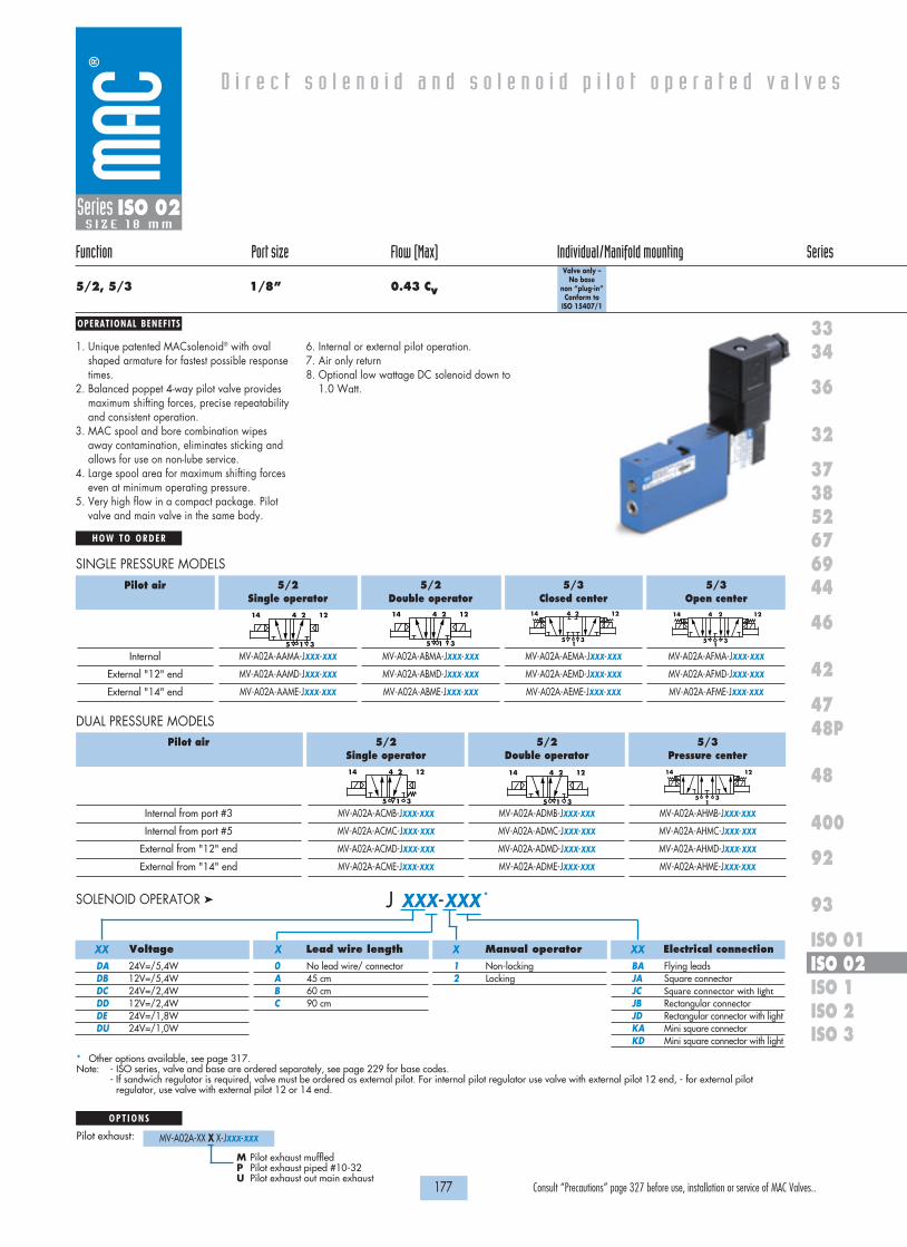
OPERATIONAL BENEFITS
D i r e c t s o l e n o i d a n d s o l e n o i d p i l o t o p e r a t e d v a l v e s
H O W T O O R D E R
177 Consult “Precautions” page 327 before use, installation or service of MAC Valves..
36
32
3738
3334
5267
46
44
47
42
400
48
92
93
ISO 1ISO 2 ISO 3
69
48P
ISO 01ISO 02
Series ISO 02S I Z E 1 8 m m
Function Port size Flow (Max) Individual/Manifold mounting Series
5/2, 5/3 1/8” 0.43 Cv
Valve only – No base
non “plug-in”Conform to
ISO 15407/1
1. Unique patented MACsolenoid® with ovalshaped armature for fastest possible responsetimes.
2. Balanced poppet 4-way pilot valve providesmaximum shifting forces, precise repeatabilityand consistent operation.
3. MAC spool and bore combination wipesaway contamination, eliminates sticking andallows for use on non-lube service.
4. Large spool area for maximum shifting forceseven at minimum operating pressure.
5. Very high flow in a compact package. Pilotvalve and main valve in the same body.
6. Internal or external pilot operation.7. Air only return8. Optional low wattage DC solenoid down to
1.0 Watt.
5/2Single operator
MV-A02A-AAMA-JXXX-XXX
MV-A02A-AAMD-JXXX-XXX
MV-A02A-AAME-JXXX-XXX
5/2Double operator
MV-A02A-ABMA-JXXX-XXX
MV-A02A-ABMD-JXXX-XXX
MV-A02A-ABME-JXXX-XXX
5/3Closed center
MV-A02A-AEMA-JXXX-XXX
MV-A02A-AEMD-JXXX-XXX
MV-A02A-AEME-JXXX-XXX
5/3Open center
MV-A02A-AFMA-JXXX-XXX
MV-A02A-AFMD-JXXX-XXX
MV-A02A-AFME-JXXX-XXX
414 2 12
5 1 3
414 2 12
5 1 3
414 2 12
51
3
414 2 12
51
3
Pilot air
Internal
External "12" end
External "14" end
SINGLE PRESSURE MODELS
5/2Single operator
MV-A02A-ACMB-JXXX-XXX
MV-A02A-ACMC-JXXX-XXX
MV-A02A-ACMD-JXXX-XXX
MV-A02A-ACME-JXXX-XXX
5/2Double operator
MV-A02A-ADMB-JXXX-XXX
MV-A02A-ADMC-JXXX-XXX
MV-A02A-ADMD-JXXX-XXX
MV-A02A-ADME-JXXX-XXX
5/3Pressure center
MV-A02A-AHMB-JXXX-XXX
MV-A02A-AHMC-JXXX-XXX
MV-A02A-AHMD-JXXX-XXX
MV-A02A-AHME-JXXX-XXX
Pilot air
Internal from port #3
Internal from port #5
External from "12" end
External from "14" end
DUAL PRESSURE MODELS
14 12
51
3
414 2 12
5 1 3
414 2 12
5 1 3
J XXX-XXX *SOLENOID OPERATOR �
Voltage
DA 24V=/5,4WDB 12V=/5,4W DC 24V=/2,4WDD 12V=/2,4WDE 24V=/1,8WDU 24V=/1,0W
Lead wire length
0 No lead wire/ connectorA 45 cmB 60 cmC 90 cm
Manual operator
1 Non-locking2 Locking
Electrical connection
BA Flying leadsJA Square connectorJC Square connector with lightJB Rectangular connectorJD Rectangular connector with lightKA Mini square connector KD Mini square connector with light
XX X X XX
* Other options available, see page 317.Note: - ISO series, valve and base are ordered separately, see page 229 for base codes.
- If sandwich regulator is required, valve must be ordered as external pilot. For internal pilot regulator use valve with external pilot 12 end, - for external pilotregulator, use valve with external pilot 12 or 14 end.
O P T I O N S
Pilot exhaust: MV-A02A-XX X X-JXXX-XXX
M Pilot exhaust muffledP Pilot exhaust piped #10-32U Pilot exhaust out main exhaust

1818100%100%
100%100% M O N T H S
WARRANTY
O FP R O D U C T I O N
T E S T E D
D I M E N S I O N S
T E C H N I C A L D A T A
Dimensions shown are metric (mm)
178 Consult “Precautions” page 327 before use, installation or service of MAC Valves..
144.0
7.511.5
7.8 27.6
42.5
12 & 141/8"
1/8"
1.3
101.9
86.5
17.5
24.840.6
Ø 5.3
11.5
25.440.4
17.7
35.0
42.0
42.050.0
104.6
12 & 141/8"
22.7 19.0
9.5
121.4
TYP. TYP.
TYP.
TYP.TYP.
TYP. (4)
12 & 141/8" 1, 3 & 5 PORTS
1/4"
10.9 15.9
32.848.3
54.8
Series ISO 02S I Z E 1 8 m m
Fluid :
Pressure range :
Pilot pressure :
Lubrication :
Filtration :
Temperature range :
Flow :
Coil :
Voltage range :
Power :
Compressed air, vacuum, inert gases
Internal Pilot - 2 pos.: 20 to 120 PSI - 3 pos.: 35 to 120 PSI
External Pilot: Vacuum to 120 PSI
2 pos.: 20 to 120 PSI - 3 pos.: 35 to 120 PSI
Not required, if used select a medium aniline point lubricant (between 180°F and 210°F)
40 µ
0°F to 120°F (-18°C to +50°C)
2 pos.: Cv 0.43 – 3 pos.: Cv 0.28
Class A wires continuous duty, #22 AWG x 18
-15% to +10% of nominal voltage
1,0 to 5,4 W
• Sandwich flow controls: FCA02A-AA (screwdriver slot adjustment).• Sandwich pressure regulator, see ‚Regulators‘ section
Options :
Individual base Manifold base

179 Consult “Precautions” page 327 before use, installation or service of MAC Valves..
Individual mounting Series
D i r e c t s o l e n o i d a n d s o l e n o i d p i l o t o p e r a t e d v a l v e s
SERIES FEATURES
36
32
3738
3334
5267
46
44
47
42
400
48
92
93
ISO 1ISO 2 ISO 3
69
48P
ISO 01ISO 02
Valve only – No base
non “plug-in”Conform to ISO 5599/1
Valve only – No base “plug-in”
Conform to ISO 5599/2
Valve only – No base “plug-in”
Conform to ISO 5599/2
Valve only – No base
non “plug-in”Conform to ISO 5599/1
Series ISO 1
Manifold mounting
• Plug-in (5599/2) and non plug-in (5599/1) models.• 2-position, single or double operator. (Solenoid or Remote Air)• 3-position, double solenoid, open center, closed center, and pressure center.• Extended or recessed manual operators.• Single pressure and dual pressure.• Individual base or add-a-unit manifold base.• Plug-in, sandwich, single and dual pressure regulators for both individual and manifold valves.
3 2 1 4 5
Manual operator
Large spool diameter
Air return
Balanced 4-way poppet
Internal pilot supplyBonded spool
External pilot supply
External pilot supply

OPERATIONAL BENEFITS
D i r e c t s o l e n o i d a n d s o l e n o i d p i l o t o p e r a t e d v a l v e s
H O W T O O R D E R
181 Consult “Precautions” page 327 before use, installation or service of MAC Valves..
36
32
3738
3334
5267
46
44
47
42
400
48
92
93
ISO 1ISO 2 ISO 3
69
48P
ISO 01ISO 02
Series ISO 1
Function Port size Flow (Max) Individual/Manifold mounting Series
5/2, 5/3 1/4” - 3/8” 1.8 Cv
Valve only – No base
non “plug-in”Conform to ISO 5599/1
1. Unique patented Macsolenoid® for fastestpossible response times and virtually burn-out proof AC solenoid operation.
2. Balanced poppet 4-way pilot valve providesmaximum shifting forces, preciserepeatability and consistent operation.
3. MAC spool and bore combination wipesaway contamination, eliminates sticking andallows for use on non-lube service.
4. Large spool area for maximum shifting forceseven at minimum operating pressure.
5. Very high flow in a compact package.
6. Plug-in design of valves, bases andregulators for modular assembly and ease ofmaintenance.
7. Internal or external pilot operation.Manifolds supplied with common externalpilot.
8. Air only return. Optional memory spring isalso available.
9. Optional low wattage DC solenoid down to1.0 watt.
DM-D XXX-XXX *SOLENOID OPERATOR �
Voltage
JA 110/50, 120/60JB 220/50, 240/60JC 24/50, 24/60FB 24 VDC (1.8W)DA 24 VDC (5.4W)DF 24 VDC (12.7W)
Lead wire length
A 18” (Flying leads)B 24” (Flying leads)J Connector
Manual operator
1 Non-locking recessed2 Locking recessed
Electrical connection
KA Square connectorKD Square connector with lightJB Rectangular connectorJD Rectangular connector with lightBA Flying leads
XX X X XX
* Other options available, see page 309.Note: ISO series, valve and base are ordered separately, see page 231 for base code.
5/2Single operator
MV-B1A-AAAA-DM-DXXX-XXX
MV-B1A-AAAB-DM-DXXX-XXX
5/2Double operator
MV-B1A-ABAA-DM-DXXX-XXX
MV-B1A-ABAB-DM-DXXX-XXX
5/3Closed center
MV-B1A-AEAA-DM-DXXX-XXX
MV-B1A-AEAB-DM-DXXX-XXX
5/3Open center
MV-B1A-AFAA-DM-DXXX-XXX
MV-B1A-AFAB-DM-DXXX-XXX
414 2 12
5 1 3
414 2 12
5 1 3
414 2 12
51
3
414 2 12
51
3
Pilot air
Internal
External "12" end
SINGLE PRESSURE MODELS
5/2Single operator
MV-B1A-ACAD-DM-DXXX-XXX
MV-B1A-ACAE-DM-DXXX-XXX
MV-B1A-ACAB-DM-DXXX-XXX
5/2Double operator
MV-B1A-ADAD-DM-DXXX-XXX
MV-B1A-ADAE-DM-DXXX-XXX
MV-B1A-ADAB-DM-DXXX-XXX
5/3Pressure center
MV-B1A-AGAD-DM-DXXX-XXX
MV-B1A-AGAE-DM-DXXX-XXX
MV-B1A-AGAB-DM-DXXX-XXX
Pilot air
Internal pilot From port #3
Internal pilot From port #5
External pilot From "12" end
DUAL PRESSURE MODELS
14 12
51
3
414 2 12
5 1 3
414 2 12
5 1 3
O P T I O N S
Valve function :
MV-B1A-AXXX-XX-DXXX-XXX
J for single operator universal spool (ext. pilot only)K for double operator universal spool (ext. pilot only)
Pilot style :
MV-B1A-AXXX-DM-DXXX-XXX
DM Pilot exhaust muffledDP Pilot exhaust piped (#10-32)
Spool return :
MV-B1A-AXAX-XX-DXXX-XXX
A Standard returnB Memory spring return
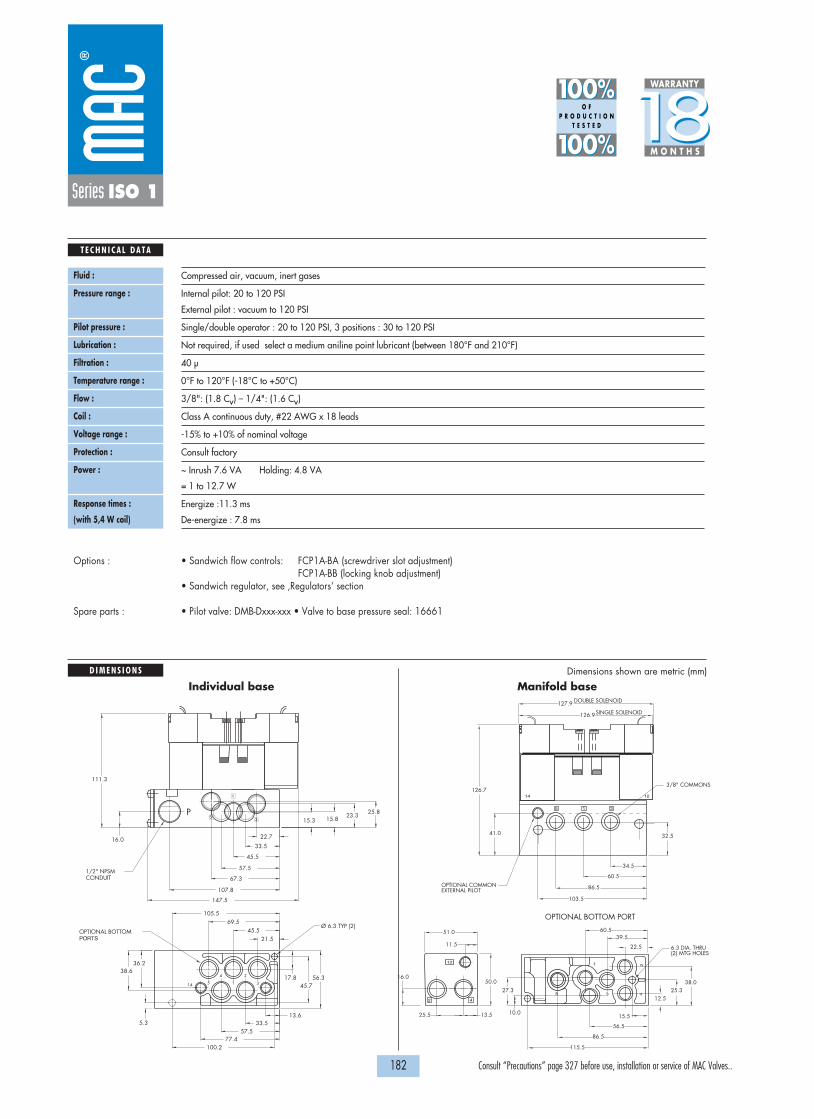
1818100%100%
100%100% M O N T H S
WARRANTY
O FP R O D U C T I O N
T E S T E D
D I M E N S I O N S
T E C H N I C A L D A T A
Dimensions shown are metric (mm)
182 Consult “Precautions” page 327 before use, installation or service of MAC Valves..
Ø 6.3 TYP (2)
PORTSOPTIONAL BOTTOM
CONDUIT1/2" NPSM
111.3
56.345.7
17.8
36.2
5.3
38.6
77.457.5
13.633.5
100.2
105.569.5
45.521.5
25.823.315.815.3
16.0
107.8
67.3
57.5
45.5
33.5
22.7
147.5
P
1
35
3
2
1
4
514
60.539.5
22.5
25.338.0
41.0
126.7
127.9 DOUBLE SOLENOID
SINGLE SOLENOID
51.0
11.5
50.0
13.525.5
16.0
126.9
3/8" COMMONS
OPTIONAL COMMONEXTERNAL PILOT
OPTIONAL BOTTOM PORT
32.5
34.5
60.5
86.5
103.5
12.5
15.5
56.5
86.5
115.5
27.3
10.0
6.3 DIA. THRU(2) MTG HOLES
42
12 1
3
24
5
15 3
1214
Series ISO 1
Fluid :
Pressure range :
Pilot pressure :
Lubrication :
Filtration :
Temperature range :
Flow :
Coil :
Voltage range :
Protection :
Power :
Response times :
(with 5,4 W coil)
Compressed air, vacuum, inert gases
Internal pilot: 20 to 120 PSI
External pilot : vacuum to 120 PSI
Single/double operator : 20 to 120 PSI, 3 positions : 30 to 120 PSI
Not required, if used select a medium aniline point lubricant (between 180°F and 210°F)
40 µ
0°F to 120°F (-18°C to +50°C)
3/8": (1.8 Cv) – 1/4": (1.6 Cv)
Class A continuous duty, #22 AWG x 18 leads
-15% to +10% of nominal voltage
Consult factory
~ Inrush 7.6 VA Holding: 4.8 VA
= 1 to 12.7 W
Energize :11.3 ms
De-energize : 7.8 ms
• Sandwich flow controls: FCP1A-BA (screwdriver slot adjustment) FCP1A-BB (locking knob adjustment)
• Sandwich regulator, see ‚Regulators‘ section
• Pilot valve: DMB-Dxxx-xxx • Valve to base pressure seal: 16661
Options :
Spare parts :
Individual base Manifold base

OPERATIONAL BENEFITS
D i r e c t s o l e n o i d a n d s o l e n o i d p i l o t o p e r a t e d v a l v e s
H O W T O O R D E R
183 Consult “Precautions” page 327 before use, installation or service of MAC Valves..
36
32
3738
3334
5267
46
44
47
42
400
48
92
93
ISO 1ISO 2 ISO 3
69
48P
ISO 01ISO 02
Series ISO 1
Function Port size Flow (Max) Individual/Manifold mounting Series
5/2, 5/3 1/4” - 3/8” 1.8 Cv
Valve only – No base “plug-in”
Conform to ISO 5599/2
1. Unique patented Macsolenoid® for fastestpossible response times and virtually burn-out proof AC solenoid operation.
2. Balanced poppet 4-way pilot valve providesmaximum shifting forces, preciserepeatability and consistent operation.
3. MAC spool and bore combination wipesaway contamination, eliminates sticking andallows for use on non-lube service.
4. Large spool area for maximum shifting forceseven at minimum operating pressure.
5. Very high flow in a compact package.
6. Plug-in design of valves, bases andregulators for modular assembly and ease ofmaintenance.
7. Internal or external pilot operation.Manifolds supplied with common externalpilot.
8. Air only return. Optional memory spring isalso available.
9. Optional low wattage DC solenoid down to1.0 watt.
* Other options available, see page 309.Note: - ISO series, valve and base are ordered separately, see page 233 for base codes.
- Ground wire required for 30 volts or higher.
5/2Single operator
MV-P1A-AAAA-DM-DXXP-XXX
MV-P1A-AAAB-DM-DXXP-XXX
5/2Double operator
MV-P1A-ABAA-DM-DXXP-XXX
MV-P1A-ABAB-DM-DXXP-XXX
5/3Closed center
MV-P1A-AEAA-DM-DXXP-XXX
MV-P1A-AEAB-DM-DXXP-XXX
5/3Open center
MV-P1A-AFAA-DM-DXXP-XXX
MV-P1A-AFAB-DM-DXXP-XXX
414 2 12
5 1 3
414 2 12
5 1 3
414 2 12
51
3
414 2 12
51
3
Pilot air
Internal
External "12" end
SINGLE PRESSURE MODELS
5/2Single operator
MV-P1A-ACAD-DM-DXXP-XXX
MV-P1A-ACAE-DM-DXXP-XXX
MV-P1A-ACAB-DM-DXXP-XXX
5/2Double operator
MV-P1A-ADAD-DM-DXXP-XXX
MV-P1A-ADAE-DM-DXXP-XXX
MV-P1A-ADAB-DM-DXXP-XXX
5/3Pressure center
MV-P1A-AGAD-DM-DXXP-XXX
MV-P1A-AGAE-DM-DXXP-XXX
MV-P1A-AGAB-DM-DXXP-XXX
Pilot air
Internal pilot From port #3
Internal pilot From port #5
External pilot From "12" end
DUAL PRESSURE MODELS
14 12
51
3
414 2 12
5 1 3
414 2 12
5 1 3
O P T I O N S
Valve function :
MV-P1A-AXXX-XX-DXXP-XXX
J for single operator universal spool (ext. pilot only)K for double operator universal spool (ext. pilot only)
Pilot style :
MV-P1A-AXXX-DM-DXXP-XXX
DM Pilot exhaust muffledDP Pilot exhaust piped (#10-32)
Spool return :
MV-P1A-AXAX-XX-DXXP-XXX
A Standard returnB Memory spring returnD Standard return with lightE Memory spring return with light
Voltage
JA 110/50, 120/60 (2.9W)JB 220/50, 240/60 (2.9W)JC 24/50, 24/60 (2.9W)FB 24 VDC (1.8W)DA 24 VDC (5.4W)DF 24 VDC (12.7W)
Manual operator
1 Non-locking recessed2 Locking recessed
Electrical connection
DM Plug-inDN Plug-in with diodeDP Plug-in with M.O.V.DG Plug-in with ground
DM-D XX P-XXX *SOLENOID OPERATOR �
XX X XX

1818100%100%
100%100% M O N T H S
WARRANTY
O FP R O D U C T I O N
T E S T E D
D I M E N S I O N S
T E C H N I C A L D A T A
Dimensions shown are metric (mm)
184 Consult “Precautions” page 327 before use, installation or service of MAC Valves..
Ø 6.3 TYP (2)
PORTSOPTIONAL BOTTOM
CONDUIT1/2" NPSM
111.3
56.345.7
17.8
36.2
5.3
38.6
77.457.5
13.633.5
100.2
105.569.5
45.521.5
25.823.315.815.3
16.0
107.8
67.3
57.5
45.5
33.522.7
147.5
P
1
35
3
2
1
4
514
Series ISO 1
Fluid :
Pressure range :
Pilot pressure :
Lubrication :
Filtration :
Temperature range :
Flow :
Coil :
Voltage range :
Protection :
Power :
Response times :
(with 5,4 W coil)
Compressed air, vacuum, inert gases
Internal pilot: 20 to 120 PSI
External pilot : vacuum to 120 PSI
Single/double operator : 20 to 120 PSI, 3 positions : 30 to 120 PSI
Not required, if used select a medium aniline point lubricant (between 180°F and 210°F)
40 µ
0°F to 120°F (-18°C to +50°C)
3/8": (1.8 Cv) – 1/4": (1.6 Cv)
Class A continuous duty, #22 AWG x 12 base leads
-15% to +10% of nominal voltage
Consult factory
~ Inrush 7.6 VA Holding: 4.8 VA
= 1 to 12.7 W
Energize :10 ms
De-energize : 9 ms
• Sandwich flow controls: FCP1A-AA (screwdriver slot adjustment) FCP1A-AB (locking knob adjustment)
• Sandwich regulator, see ‚Regulators‘ section
• Pilot valve: DMB-DxxP-xxx • Valve to base pressure seal: 16661
Options :
Spare parts :
5
3
1
2
2 4
12
4
COND
3
5
1 20.9 32.229.7 40.5
127.0
6.926.0
32.241.0
108.5
20.238.5
65.590.7
92.0
132.8115.2
159.3
24.0 12.0
15.0
42.015.0
25.4
46.2
70.790.3
15.990.5
15.528.032.0
52.0
13.0
13.728.0
40.0
52.0
CONDUIT1" NPSM
TYP(3)3/8" COMMONS
EXTERNAL PILOT 1/8"OPTIONAL COMMON
PORTSOPTIONAL BOTTOM (2) MTG HOLES
Ø 6.3 THRU
Individual base Manifold base

185 Consult “Precautions” page 327 before use, installation or service of MAC Valves..
Individual mounting Series
D i r e c t s o l e n o i d a n d s o l e n o i d p i l o t o p e r a t e d v a l v e s
SERIES FEATURES
36
32
3738
3334
5267
46
44
47
42
400
48
92
93
ISO 1ISO 2 ISO 3
69
48P
ISO 01ISO 02
Series ISO 2
• Plug-in (5599/2) and non plug-in (5599/1) models.• 2-position, single or double operator. (Solenoid or Remote Air)• 3-position, double solenoid, open center, closed center, and pressure center.• Extended or recessed manual operators.• Single pressure and dual pressure.• Individual base or add-a-unit manifold base.• Plug-in, sandwich, single and dual pressure regulators for both individual and manifold valves.
3 2 1 4 5
Manual operator
Large spool diameter
Air return
Balanced 4-way poppet
Internal pilot supplyBonded spool
External pilot supply
External pilot supply
Valve only – No base
non “plug-in”Conform to ISO 5599/1
Valve only – No base “plug-in”
Conform to ISO 5599/2
Valve only – No base “plug-in”
Conform to ISO 5599/2
Valve only – No base
non “plug-in”Conform to ISO 5599/1
Manifold mounting

OPERATIONAL BENEFITS
D i r e c t s o l e n o i d a n d s o l e n o i d p i l o t o p e r a t e d v a l v e s
H O W T O O R D E R
187 Consult “Precautions” page 327 before use, installation or service of MAC Valves..
36
32
3738
3334
5267
46
44
47
42
400
48
92
93
ISO 1ISO 2 ISO 3
69
48P
ISO 01ISO 02
Series ISO 2
Function Port size Flow (Max) Individual/Manifold mounting Series
5/2, 5/3 3/8” - 1/2” 3.0 Cv
Valve only – No base
non “plug-in”Conform to ISO 5599/1
1. Unique patented Macsolenoid® for fastestpossible response times and virtually burn-out proof AC solenoid operation.
2. Balanced poppet 4-way pilot valve providesmaximum shifting forces, preciserepeatability and consistent operation.
3. MAC spool and bore combination wipesaway contamination, eliminates sticking andallows for use on non-lube service.
4. Large spool area for maximum shifting forceseven at minimum operating pressure.
5. Very high flow in a compact package.
6. Plug-in design of valves, bases andregulators for modular assembly and ease ofmaintenance.
7. Internal or external pilot operation.Manifolds supplied with common externalpilot.
8. Air only return. Optional memory spring isalso available.
9. Optional low wattage DC solenoid down to1.0 watt.
DM-D XXX-XXX *SOLENOID OPERATOR �
Voltage
JA 110/50, 120/60JB 220/50, 240/60JC 24/50, 24/60FB 24 VDC (1.8W)DA 24 VDC (5.4W)DF 24 VDC (12.7W)
Lead wire length
A 18” (Flying leads)B 24” (Flying leads)J Connector
Manual operator
1 Non-locking recessed2 Locking recessed
Electrical connection
KA Square connectorKD Square connector with lightJB Rectangular connectorJD Rectangular connector with lightBA Flying leads
XX X X XX
* Other options available, see page 309.Note: ISO series, valve and base are ordered separately, see page 235 for base code.
5/2Single operator
MV-B2A-AAAA-DM-DXXX-XXX
MV-B2A-AAAB-DM-DXXX-XXX
5/2Double operator
MV-B2A-ABAA-DM-DXXX-XXX
MV-B2A-ABAB-DM-DXXX-XXX
5/3Closed center
MV-B2A-AEAA-DM-DXXX-XXX
MV-B2A-AEAB-DM-DXXX-XXX
5/3Open center
MV-B2A-AFAA-DM-DXXX-XXX
MV-B2A-AFAB-DM-DXXX-XXX
414 2 12
5 1 3
414 2 12
5 1 3
414 2 12
51
3
414 2 12
51
3
Pilot air
Internal
External "12" end
SINGLE PRESSURE MODELS
5/2Single operator
MV-B2A-ACAD-DM-DXXX-XXX
MV-B2A-ACAE-DM-DXXX-XXX
MV-B2A-ACAB-DM-DXXX-XXX
5/2Double operator
MV-B2A-ADAD-DM-DXXX-XXX
MV-B2A-ADAE-DM-DXXX-XXX
MV-B2A-ADAB-DM-DXXX-XXX
5/3Pressure center
MV-B2A-AGAD-DM-DXXX-XXX
MV-B2A-AGAE-DM-DXXX-XXX
MV-B2A-AGAB-DM-DXXX-XXX
Pilot air
Internal pilot From port #3
Internal pilot From port #5
External pilot From "12" end
DUAL PRESSURE MODELS
14 12
51
3
414 2 12
5 1 3
414 2 12
5 1 3
O P T I O N S
Valve function :
MV-B2A-AXXX-XX-DXXX-XXX
J for single operator universal spool (ext. pilot only)K for double operator universal spool (ext. pilot only)
Pilot style :
MV-B2A-AXXX-DM-DXXX-XXX
DM Pilot exhaust muffledDP Pilot exhaust piped (#10-32)
Spool return :
MV-B2A-AXAX-XX-DXXX-XXX
A Standard returnB Memory spring return

4 25 3
1
135
4 2
5
2
4
31
163.9163.9
138.0
128.9
120.5
124.9
42.0
23.0
86.072.0
56.0
32.0
87.0
62.0
21.5
53.5
56.025.0
12.0
25.5
47.568.5
38.074.0
100.0
98.0 OPTIONAL BTM PORTS7.5 DIA. THRU2 MTG. HOLES
38.0
1/8 EXT.PILOT
40.0
26.0
32.0
151.0
139.0 SINGLE & DOUBLESOLENOID
124.9
54.0
39.0
1/2" SIDE PORTS(3) EACH SIDE
OPTIONAL BTM.PORTS
104.0
70.0
36.0
20.0
42.0
50.5
1/8" EXT.PILOT
70.0
26.023.0 34.0 7.0
52.030.5
64.09.0
112.0132.0
139.0
30.032.0
6.5 DIA.2 MTG. HOLES
14.5
1818100%100%
100%100% M O N T H S
WARRANTY
O FP R O D U C T I O N
T E S T E D
D I M E N S I O N S
T E C H N I C A L D A T A
Dimensions shown are metric (mm)
188 Consult “Precautions” page 327 before use, installation or service of MAC Valves..
Series ISO 2
Fluid :
Pressure range :
Pilot pressure :
Lubrication :
Filtration :
Temperature range :
Flow :
Coil :
Voltage range :
Protection :
Power :
Response times :
Compressed air, vacuum, inert gases
Internal pilot: 20 to 120 PSI
External pilot : vacuum to 120 PSI
Single/double operator : 20 to 120 PSI, 3 positions : 30 to 120 PSI
Not required, if used select a medium aniline point lubricant (between 180°F and 210°F)
40 µ
0°F to 120°F (-18°C to +50°C)
3/8": (2.8 Cv) - 1/2": (3.0 Cv)
Class A continuous duty, #22 AWG x 18 leads
-15% to +10% of nominal voltage
Consult factory
~ Inrush 7.6 VA Holding: 4.8 VA
= 12.7 to 1.0 W
24 VDC 5.4w Energize : 10 ms De-energize : 9.6 ms
120/60 Energize : 6-15 ms De-energize : 10-17 ms
• Sandwich flow controls: FCP2A-BA (screwdriver slot adjustment) FCP2A-BB (locking knob adjustment)
• Sandwich regulator, see ‚Regulators‘ section
• Pilot valve: DMB-Dxxx-xxx • Valve to base pressure seal: 16576• Valve mounting screws (x4): 35413
Options :
Spare parts :
Individual base Manifold base

OPERATIONAL BENEFITS
D i r e c t s o l e n o i d a n d s o l e n o i d p i l o t o p e r a t e d v a l v e s
H O W T O O R D E R
189 Consult “Precautions” page 327 before use, installation or service of MAC Valves..
36
32
3738
3334
5267
46
44
47
42
400
48
92
93
ISO 1ISO 2 ISO 3
69
48P
ISO 01ISO 02
Series ISO 2
Function Port size Flow (Max) Individual/Manifold mounting Series
5/2, 5/3 3/8” - 1/2” 3.0 Cv
Valve only – No base “plug-in”
Conform to ISO 5599/2
1. Unique patented Macsolenoid® for fastestpossible response times and virtually burn-out proof AC solenoid operation.
2. Balanced poppet 4-way pilot valve providesmaximum shifting forces, preciserepeatability and consistent operation.
3. MAC spool and bore combination wipesaway contamination, eliminates sticking andallows for use on non-lube service.
4. Large spool area for maximum shifting forceseven at minimum operating pressure.
5. Very high flow in a compact package.
6. Plug-in design of valves, bases andregulators for modular assembly and ease ofmaintenance.
7. Internal or external pilot operation.Manifolds supplied with common externalpilot.
8. Air only return. Optional memory spring isalso available.
9. Optional low wattage DC solenoid down to1.0 watt.
* Other options available, see page 309.Note: - ISO series, valve and base are ordered separately, see page 237 for base codes.
- Ground wire required for 30 volts or higher.
5/2Single operator
MV-P2A-AAAA-DM-DXXP-XXX
MV-P2A-AAAB-DM-DXXP-XXX
5/2Double operator
MV-P2A-ABAA-DM-DXXP-XXX
MV-P2A-ABAB-DM-DXXP-XXX
5/3Closed center
MV-P2A-AEAA-DM-DXXP-XXX
MV-P2A-AEAB-DM-DXXP-XXX
5/3Open center
MV-P2A-AFAA-DM-DXXP-XXX
MV-P2A-AFAB-DM-DXXP-XXX
414 2 12
5 1 3
414 2 12
5 1 3
414 2 12
51
3
414 2 12
51
3
Pilot air
Internal
External "12" end
SINGLE PRESSURE MODELS
5/2Single operator
MV-P2A-ACAD-DM-DXXP-XXX
MV-P2A-ACAE-DM-DXXP-XXX
MV-P2A-ACAB-DM-DXXP-XXX
5/2Double operator
MV-P2A-ADAD-DM-DXXP-XXX
MV-P2A-ADAE-DM-DXXP-XXX
MV-P2A-ADAB-DM-DXXP-XXX
5/3Pressure center
MV-P2A-AGAD-DM-DXXP-XXX
MV-P2A-AGAE-DM-DXXP-XXX
MV-P2A-AGAB-DM-DXXP-XXX
Pilot air
Internal pilot From port #3
Internal pilot From port #5
External pilot From "12" end
DUAL PRESSURE MODELS
14 12
51
3
414 2 12
5 1 3
414 2 12
5 1 3
O P T I O N S
Valve function :
MV-P2A-AXXX-XX-DXXP-XXX
J for single operator universal spool (ext. pilot only)K for double operator universal spool (ext. pilot only)
Pilot style :
MV-P2A-AXXX-DM-DXXP-XXX
DM Pilot exhaust muffledDP Pilot exhaust piped (#10-32)
Spool return :
MV-P2A-AXAX-XX-DXXP-XXX
A Standard returnB Memory spring returnD Standard return with lightE Memory spring return with light
Voltage
JA 110/50, 120/60JB 220/50, 240/60JC 24/50, 24/60FB 24 VDC (1.8W)DA 24 VDC (5.4W)DF 24 VDC (12.7W)
Manual operator
1 Non-locking recessed2 Locking recessed
Electrical connection
DM Plug-inDN Plug-in with diodeDP Plug-in with M.O.V.DG Plug-in with ground
DM-D XX P-XXX *SOLENOID OPERATOR �
XX X XX

1818100%100%
100%100% M O N T H S
WARRANTY
O FP R O D U C T I O N
T E S T E D
D I M E N S I O N S
T E C H N I C A L D A T A
190 Consult “Precautions” page 327 before use, installation or service of MAC Valves..
COND
3
5
1
5
1
3
42
SIDE CYL.CENT. OF 1/2"
SIDE CYL.CENT. OF 3/8"
SOLENOIDSINGLE & DOUBLE 187.0
18.3 105.5
50.0 39.5
38.0
37.0
19.0 17.5
11.3
35.5 71.5
103.0
26.0 30.0
38.0
103.0 45.0
22.0
15.0 30.0
45.0
77.0168.00 5.50
45.0
60.0
(2)MTG HOLES6.5 DIA. THRU
18.5
#14
PILOT 1/8"#14 EXTERNAL
#12
18.0
8.5
50.0
41.5
134.1PILOT 1/8"#12 EXTERNAL
CONDUIT1-1/4" N.P.S.M.
EXTERNAL PILOT 1/8"OPTIONAL COMMON
PORTSOPTIONAL BOTTOM
51.0
6.0
173.8
34.0B
PORTSOPTIONAL BOTTOM
CONDUIT1/2" N.P.S.M.
(2)MTG HOLES6.5 DIA. THRU
54.50
5.5
#14#12
22.0 24.5
PILOT 1/8"#14 EXTERNAL
34.5 34.5
PILOT 1/8"#12 EXTERNAL
119.25 5.5
SINGLE SOLENOID
DOUBLE SOLENOID
146.8
22.0
125.0
55.0
AC
GF
ED
65.5
17.0
48.5
81.0
51.0
20.5
43.5
40.0
70.0
140.0
1
3
2 4
5
115.9
156.1
42
Series ISO 2
Fluid :
Pressure range :
Pilot pressure :
Lubrication :
Filtration :
Temperature range :
Flow :
Coil :
Voltage range :
Protection :
Power :
Response times :
Compressed air, vacuum, inert gases
Internal pilot: 20 to 120 PSI
External pilot : vacuum to 120 PSI
Single/double operator : 20 to 120 PSI, 3 positions : 30 to 120 PSI
Not required, if used select a medium aniline point lubricant (between 180°F and 210°F)
40 µ
0°F to 120°F (-18°C to +50°C)
3/8": (2.8 Cv) - 1/2": (3.0 Cv)
Class A continuous duty, #18 AWG x 12 base leads
-15% to +10% of nominal voltage
Consult factory
~ Inrush 14.8 VA Holding: 10.9 VA
= 12.7 to 1.0 W
24 VDC 5.4w Energize : 10 ms De-energize : 9.6 ms
120/60 Energize : 6-15 ms De-energize : 10-17 ms
• Sandwich flow controls: FCP2A-AA (screwdriver slot adjustment) FCP2A-AB (locking knob adjustment)
• Sandwich regulator, see ‚Regulators‘ section
• Pilot valve: DMB-DxxP-xxx • Valve to base pressure seal: 16576• Valve mounting screws (x4): 35413
Options :
Spare parts :
Individual base Manifold base
DIM.
3/8"
1/2"
A
25.2
24.0
B
22.7
21.0
C
20.6
19.0
D
26.7
25.5
E
40.5
40.0
F
69.4
70.0
G
83.3
84.5

191 Consult “Precautions” page 327 before use, installation or service of MAC Valves..
Individual mounting Series
D i r e c t s o l e n o i d a n d s o l e n o i d p i l o t o p e r a t e d v a l v e s
SERIES FEATURES
36
32
3738
3334
5267
46
44
47
42
400
48
92
93
ISO 1ISO 2 ISO 3
69
48P
ISO 01ISO 02
Series ISO 3
• Plug-in (5599/2) and non plug-in (5599/1) models.• 2-position, single or double operator. (Solenoid or Remote Air)• 3-position, double solenoid, open center, closed center, and pressure center.• Extended or recessed manual operators.• Single pressure and dual pressure.• Individual base or add-a-unit manifold base.• Plug-in, sandwich, single and dual pressure regulators for both individual and manifold valves.
3 2 1 4 5
Manual operator
Large spool diameter
Air return
Balanced 4-way poppet
Internal pilot supplyBonded spool
External pilot supply
External pilot supply
Valve only – No base
non “plug-in”Conform to ISO 5599/1
Valve only – No base “plug-in”
Conform to ISO 5599/2
Valve only – No base “plug-in”
Conform to ISO 5599/2
Valve only – No base
non “plug-in”Conform to ISO 5599/1
Manifold mounting

OPERATIONAL BENEFITS
D i r e c t s o l e n o i d a n d s o l e n o i d p i l o t o p e r a t e d v a l v e s
H O W T O O R D E R
193 Consult “Precautions” page 327 before use, installation or service of MAC Valves..
36
32
3738
3334
5267
46
44
47
42
400
48
92
93
ISO 1ISO 2 ISO 3
69
48P
ISO 01ISO 02
Series ISO 3
Function Port size Flow (Max) Individual/Manifold mounting Series
5/2, 5/3 1/2” - 3/4” 6.1 Cv
Valve only – No base
“non plug-in”Conform to ISO 5599/1
1. Unique patented Macsolenoid® for fastestpossible response times and virtually burn-out proof AC solenoid operation.
2. Balanced poppet 4-way pilot valve providesmaximum shifting forces, preciserepeatability and consistent operation.
3. MAC spool and bore combination wipesaway contamination, eliminates sticking andallows for use on non-lube service.
4. Large spool area for maximum shifting forceseven at minimum operating pressure.
5. Very high flow in a compact package.
6. Plug-in design of valves, bases andregulators for modular assembly and ease ofmaintenance.
7. Internal or external pilot operation.Manifolds supplied with common externalpilot.
8. Air only return. Optional memory spring isalso available.
9. Optional low wattage DC solenoid down to1.0 watt.
DM-D XXX-XXX *SOLENOID OPERATOR �
Voltage
JA 110/50, 120/60JB 220/50, 240/60JC 24/50, 24/60FB 24 VDC (1.8W)DA 24 VDC (5.4W)DF 24 VDC (12.7W)
Lead wire length
A 18” (Flying leads)B 24” (Flying leads)J Connector
Manual operator
1 Non-locking recessed2 Locking recessed
Electrical connection
KA Square connectorKD Square connector with lightJB Rectangular connectorJD Rectangular connector with lightBA Flying leads
XX X X XX
* Other options available, see page 309.Note: ISO series, valve and base are ordered separately, see page 239 for base code.
5/2Single operator
MV-B3A-AAAA-DM-DXXX-XXX
MV-B3A-AAAB-DM-DXXX-XXX
5/2Double operator
MV-B3A-ABAA-DM-DXXX-XXX
MV-B3A-ABAB-DM-DXXX-XXX
5/3Closed center
MV-B3A-AEAA-DM-DXXX-XXX
MV-B3A-AEAB-DM-DXXX-XXX
5/3Open center
MV-B3A-AFAA-DM-DXXX-XXX
MV-B3A-AFAB-DM-DXXX-XXX
414 2 12
5 1 3
414 2 12
5 1 3
414 2 12
51
3
414 2 12
51
3
Pilot air
Internal
External "12" end
SINGLE PRESSURE MODELS
5/2Single operator
MV-B3A-ACAD-DM-DXXX-XXX
MV-B3A-ACAE-DM-DXXX-XXX
MV-B3A-ACAB-DM-DXXX-XXX
5/2Double operator
MV-B3A-ADAD-DM-DXXX-XXX
MV-B3A-ADAE-DM-DXXX-XXX
MV-B3A-ADAB-DM-DXXX-XXX
5/3Pressure center
MV-B3A-AGAD-DM-DXXX-XXX
MV-B3A-AGAE-DM-DXXX-XXX
MV-B3A-AGAB-DM-DXXX-XXX
Pilot air
Internal pilot From port #3
Internal pilot From port #5
External pilot From "12" end
DUAL PRESSURE MODELS
14 12
51
3
414 2 12
5 1 3
414 2 12
5 1 3
O P T I O N S
Valve function :
MV-B3A-AXXX-XX-DXXX-XXX
J for single operator universal spool (ext. pilot only)K for double operator universal spool (ext. pilot only)
Pilot style :
MV-B3A-AXXX-DM-DXXX-XXX
DM Pilot exhaust muffledDP Pilot exhaust piped (#10-32)
Spool return :
MV-B3A-AXAX-XX-DXXX-XXX
A Standard returnB Memory spring return

26.5
50.077,9
23.02 4
12
19.0 40.0
P
31.0
160.8
33.4 27.0
59.0
39.0 19.0
208.0 9.0 55.7
99.9136.4
25.8
5
13
24
139.9
188.9175.2
162.0140.0
96.0 50.2
17.3
232.1
VA
C T
O 1
20 P
SIW
AT
TS
ELE
CT
RIC
AL
MO
DE
L
MO
DIF
.
AU
CK
LAN
D,N
.Z.
LIE
GE
,BE
LGIU
MW
IXO
M,M
I. U
SA
3
5
1
COND
32.8 48.8
65.8
27.8 48.0
47.0 63.3
78.0
2 MTG HOLES8.25 DIA. THRU
1818100%100%
100%100% M O N T H S
WARRANTY
O FP R O D U C T I O N
T E S T E D
D I M E N S I O N S
T E C H N I C A L D A T A
Dimensions shown are metric (mm)
194 Consult “Precautions” page 327 before use, installation or service of MAC Valves..
Series ISO 3
Fluid :
Pressure range :
Pilot pressure :
Lubrication :
Filtration :
Temperature range :
Flow :
Coil :
Voltage range :
Protection :
Power :
Response times :
(5.4 W coil)
Compressed air, vacuum, inert gases
Internal pilot: 20 to 120 PSI
External pilot : vacuum to 120 PSI
Single/double operator : 20 to 120 PSI, 3 positions : 30 to 120 PSI
Not required, if used select a medium aniline point lubricant (between 180°F and 210°F)
40 µ
0°F to 120°F (-18°C to +50°C)
1/2": (5.4 Cv) – 3/4": (6.1 Cv)
Class A continuous duty, #22 AWG leads
-15% to +10% of nominal voltage
Consult factory
~ Inrush 7.6 VA Holding: 4.8 VA
= 12.7 to 1.0 W
Energize : 16.2 ms
De-energize : 13.6 ms
• Sandwich regulator, see ‚Regulators‘ section
• Pilot valve: DMB-Dxxx-xxx • Valve to base pressure seal: 16614• Valve mounting screws (x4): 35451
Options :
Spare parts :
4 25 3
1
51
3
24
190.4 DOUBLE SOLENOID W/EXTENDED OVERRIDE
SINGLE SOLENOID W/EXTENDED OVERRIDE 175.0
160.0
138.5
33.027.0
127.0
126.077.0
28.07.5
66.5
64.0
7.059.5
94.5
140.0
54.5
24.518.5
8.3 DIA. THRU4 MTG. HOLES
OPTIONAL BTM PORTS
98.5
78.0
57.5
29.0
23.5
44.5
Individual base Manifold base
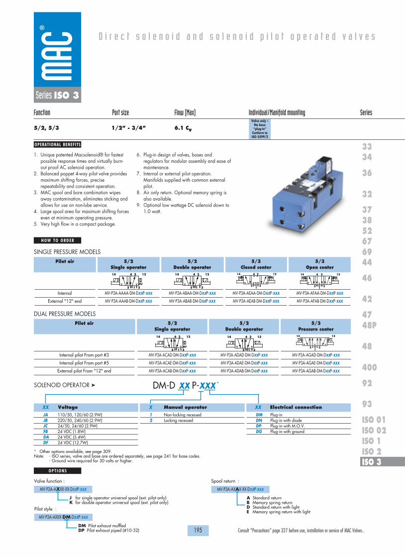
OPERATIONAL BENEFITS
D i r e c t s o l e n o i d a n d s o l e n o i d p i l o t o p e r a t e d v a l v e s
H O W T O O R D E R
195 Consult “Precautions” page 327 before use, installation or service of MAC Valves..
36
32
3738
3334
5267
46
44
47
42
400
48
92
93
ISO 1ISO 2 ISO 3
69
48P
ISO 01ISO 02
Series ISO 3
Function Port size Flow (Max) Individual/Manifold mounting Series
5/2, 5/3 1/2” - 3/4” 6.1 Cv
Valve only – No base “plug-in”
Conform to ISO 5599/2
1. Unique patented Macsolenoid® for fastestpossible response times and virtually burn-out proof AC solenoid operation.
2. Balanced poppet 4-way pilot valve providesmaximum shifting forces, preciserepeatability and consistent operation.
3. MAC spool and bore combination wipesaway contamination, eliminates sticking andallows for use on non-lube service.
4. Large spool area for maximum shifting forceseven at minimum operating pressure.
5. Very high flow in a compact package.
6. Plug-in design of valves, bases andregulators for modular assembly and ease ofmaintenance.
7. Internal or external pilot operation.Manifolds supplied with common externalpilot.
8. Air only return. Optional memory spring isalso available.
9. Optional low wattage DC solenoid down to1.0 watt.
* Other options available, see page 309.Note: - ISO series, valve and base are ordered separately, see page 241 for base codes.
- Ground wire required for 30 volts or higher.
5/2Single operator
MV-P3A-AAAA-DM-DXXP-XXX
MV-P3A-AAAB-DM-DXXP-XXX
5/2Double operator
MV-P3A-ABAA-DM-DXXP-XXX
MV-P3A-ABAB-DM-DXXP-XXX
5/3Closed center
MV-P3A-AEAA-DM-DXXP-XXX
MV-P3A-AEAB-DM-DXXP-XXX
5/3Open center
MV-P3A-AFAA-DM-DXXP-XXX
MV-P3A-AFAB-DM-DXXP-XXX
414 2 12
5 1 3
414 2 12
5 1 3
414 2 12
51
3
414 2 12
51
3
Pilot air
Internal
External "12" end
SINGLE PRESSURE MODELS
5/2Single operator
MV-P3A-ACAD-DM-DXXP-XXX
MV-P3A-ACAE-DM-DXXP-XXX
MV-P3A-ACAB-DM-DXXP-XXX
5/2Double operator
MV-P3A-ADAD-DM-DXXP-XXX
MV-P3A-ADAE-DM-DXXP-XXX
MV-P3A-ADAB-DM-DXXP-XXX
5/3Pressure center
MV-P3A-AGAD-DM-DXXP-XXX
MV-P3A-AGAE-DM-DXXP-XXX
MV-P3A-AGAB-DM-DXXP-XXX
Pilot air
Internal pilot From port #3
Internal pilot From port #5
External pilot From "12" end
DUAL PRESSURE MODELS
14 12
51
3
414 2 12
5 1 3
414 2 12
5 1 3
O P T I O N S
Valve function :
MV-P3A-AXXX-XX-DXXP-XXX
J for single operator universal spool (ext. pilot only)K for double operator universal spool (ext. pilot only)
Pilot style :
MV-P3A-AXXX-DM-DXXP-XXX
DM Pilot exhaust muffledDP Pilot exhaust piped (#10-32)
Spool return :
MV-P3A-AXAX-XX-DXXP-XXX
A Standard returnB Memory spring returnD Standard return with lightE Memory spring return with light
Voltage
JA 110/50, 120/60 (2.9W)JB 220/50, 240/60 (2.9W)JC 24/50, 24/60 (2.9W)FB 24 VDC (1.8W)DA 24 VDC (5.4W)DF 24 VDC (12.7W)
Manual operator
1 Non-locking recessed2 Locking recessed
Electrical connection
DM Plug-inDN Plug-in with diodeDP Plug-in with M.O.V.DG Plug-in with ground
DM-D XX P-XXX *SOLENOID OPERATOR �
XX X XX

26.5
50.077,9
23.02 4
12
19.0 40.0
P
31.0
160.8
33.4 27.0
59.0
39.0 19.0
208.0 9.0 55.7
99.9136.4
25.8
5
13
24
139.9
188.9175.2
162.0140.0
96.0 50.2
17.3
232.1
VA
C T
O 1
20 P
SIW
AT
TS
ELE
CT
RIC
AL
MO
DE
L
MO
DIF
.
AU
CK
LAN
D,N
.Z.
LIE
GE
,BE
LGIU
MW
IXO
M,M
I. U
SA
3
5
1
COND
32.8 48.8
65.8
27.8 48.0 47.0
63.3
78.0
2 MTG HOLES8.25 DIA. THRU
1818100%100%
100%100% M O N T H S
WARRANTY
O FP R O D U C T I O N
T E S T E D
D I M E N S I O N S
T E C H N I C A L D A T A
Dimensions shown are metric (mm)
196 Consult “Precautions” page 327 before use, installation or service of MAC Valves..
Series ISO 3
Fluid :
Pressure range :
Pilot pressure :
Lubrication :
Filtration :
Temperature range :
Flow :
Coil :
Voltage range :
Protection :
Power :
Response times :
(5.4 W coil)
Compressed air, vacuum, inert gases
Internal pilot: 20 to 120 PSI
External pilot : vacuum to 120 PSI
Single/double operator : 20 to 120 PSI, 3 positions : 30 to 120 PSI
Not required, if used select a medium aniline point lubricant (between 180°F and 210°F)
40 µ
0°F to 120°F (-18°C to +50°C)
1/2": (5.4 Cv) – 3/4": (6.1 Cv)
Class A continuous duty, #22 AWG leads
-15% to +10% of nominal voltage
Consult factory
~ Inrush 7.6 VA Holding: 4.8 VA
= 12.7 to 1.0 W
Energize : 16.2 ms
De-energize : 13.6 ms
• Sandwich regulator, see ‚Regulators‘ section
• Pilot valve: DMB-DxxP-xxx • Valve to base pressure seal: 16614• Valve mounting screws (x4): 35451
Options :
Spare parts :
8.25 DIA THRU2 MTG HOLES
79.0
166.5
158.0
114.0
86.5 51.5
24.0
107.0
69.0
31.0
54.5
69.5
62.0
24.5 8.5
142.0106.5
89.5
69.0
48.5
31.0
193.0
139.4
28.5 29.0 23.5
AUCK
LAN
D,N
.Z.
LIEG
E,BE
LGIU
MW
IXO
M,M
I. US
AM
OD
IF.
MO
DEL
ELEC
TRIC
AL
WA
TTS
VAC
TO
120
PSI
4
5 3
2
1
14 12
Individual base Manifold base

197 Consult “Precautions” page 327 before use, installation or service of MAC Valves..
S e c t i o n 2 Remote a i r va lves


67
69
ISO 2
ISO 3
400
199 Consult “Precautions” page 327 before use, installation or service of MAC Valves..
R e m o t e a i r v a l v e s
Function Port size Flow (Max) Cv Individual mounting Manifold mounting Series
5/2 - 5/3
3/2
3/2 - 2/2
5/2 - 5/3
5/2 - 5/3
1/8” - 1/4”
3/4” - 1”
1 1/2” - 2” - 2 1/2”
3/8” - 1/2”
1/2” - 3/4”
1.0
20.0
60.0
3.1
6.2
Inline Sub-base non “plug-in”
Valve only –no base
Valve only –no base
P. 203 P. 205
P. 209
P. 213
P. 217 P. 217
P. 221 P. 221

R e m o t e a i r v a l v e s
201 Consult “Precautions” page 327 before use, installation or service of MAC Valves..
Individual mounting Series
67
69
ISO 2
ISO 3
400
Inline Sub-base non “plug-in”
Series 400

OPERATIONAL BENEFITS
H O W T O O R D E R
203 Consult “Precautions” page 327 before use, installation or service of MAC Valves..
R e m o t e a i r v a l v e s
67
69
ISO 2
ISO 3
400
Series 400
Function Port size Flow (Max) Individual mounting Series
5/2 – 5/3 1/8" – 1/4" 1.0 Cv Inline
1. Balanced spool, immune to variations ofpressure, also provides high flow.
2. Bonded spool with minimum friction, shiftingin a glass-like finished bore.
3. Wiping effect eliminates sticking.4. Long service life.5. Short stroke with high flow.
5/2Single operator
411A-A0H-RA Mod 1493
411A-B0H-RA Mod 1493
5/2Double operator
421A-A0H-RA
421A-B0H-RA
5/3Closed center
451A-A0H-RA
451A-B0H-RA
5/3Open center
461A-A0H-RA
461A-B0H-RA
5/3Pressure center
471A-A0H-RA
471A-B0H-RA
2 412 14
3 1 5
2 412 14
3 1 5
2 412 14
3 1 5
2 412 14
3 1 5
2 412 14
3 1 5
Pilot air
1/8” NPTF
1/4” NPTF
SINGLE PRESSURE VALVES
5/2Double operator
441A-A0H-RA
441A-B0H-RA
Port size
1/8” NPTF
1/4” NPTF
DUAL PRESSURE VALVES
2 412 14
3 1 5

25 TO 120 PSI
12
14
DOUBLE REMOTE SINGLE REMOTE
6.0
15.0
21.0
10.0
21.5
9.0
19.0
76.5
36.0
# 10-32 OR M5 PILOT PORTS
1818100%100%
100%100% M O N T H S
WARRANTY
O FP R O D U C T I O N
T E S T E D
D I M E N S I O N S
T E C H N I C A L D A T A
Dimensions shown are metric (mm)
204 Consult “Precautions” page 327 before use, installation or service of MAC Valves..
Series 400
Fluid :
Pressure range :
Air signal pressure :
Lubrication :
Filtration :
Temperature range :
Flow :
Note :
Compressed air, vacuum, inert gases
Single operator: vacuum to 100 PSI Double operator: vacuum to 150 PSI
Single oper.: 40 to 150 PSI Double oper., 2 pos.: 20 to 150 PSI, 3 pos.: 35 to 150 PSI
Not required, if used select a medium aniline point lubricant (between 180°F and 210°F)
40µ
0°F to 120°F (-18°C to 50°C)
1.0 Cv
Air signal must be ≥ main valve pressure
• BSPP threadsOption :

OPERATIONAL BENEFITS
H O W T O O R D E R
205 Consult “Precautions” page 327 before use, installation or service of MAC Valves..
R e m o t e a i r v a l v e s
67
69
ISO 2
ISO 3
400
Series 400
Function Port size Flow (Max) Individual mounting Series
5/2 – 5/3 1/8" – 1/4" 1.0 CvSub-base
non “plug-in”
1. Balanced spool, immune to variations ofpressure, also provides high flow.
2. Bonded spool with minimum friction, shiftingin a glass-like finished bore.
3. Wiping effect eliminates sticking.4. Long service life.5. Short stroke with high flow.
5/2Single operator
413A-00H-RA
413A-AAH-RA Mod 1493
413A-BAH-RA Mod 1493
5/2Double operator
423A-00H-RA
423A-AAH-RA
423A-BAH-RA
5/3Closed center
453A-00H-RA
453A-AAH-RA
453A-BAH-RA
5/3Open center
463A-00H-RA
463A-AAH-RA
463A-BAH-RA
5/3Pressure center
473A-00H-RA
473A-AAH-RA
473A-BAH-RA
2 412 14
3 1 5
2 412 14
3 1 5
2 412 14
3 1 5
2 412 14
3 1 5
2 412 14
3 1 5
Port size
Valve less base
1/8” NPTF
1/4” NPTF
SINGLE PRESSURE VALVES
5/2Double operator
443A-AAH-RA
443A-BAH-RA
Port size
1/8” NPTF
1/4” NPTF
DUAL PRESSURE VALVES
2 412 14
3 1 5
423A-AAH-RA
O P T I O N S
B for base with flow controls

MIG. HOLES4.30 DIA. (2)
33.138.1 28.10
53.005.0
TYPICALOPTIONAL FLOW CONTROLS
1/4" - 18 N.P.T.F.1/8" - 27 N.P.T.F.20.031.0
STOCK REF. 19.05
9.5 REF.
62.0
31.010.0
14
12
LC
42
25 TO 120 PSI
14
12
2 4
3 1 5
14
12
82.5
91.7
55.0
DOUBLE REMOTE
#10-32 pilot port
SINGLE REMOTE
1818100%100%
100%100% M O N T H S
WARRANTY
O FP R O D U C T I O N
T E S T E D
D I M E N S I O N S
T E C H N I C A L D A T A
Dimensions shown are metric (mm)
206 Consult “Precautions” page 327 before use, installation or service of MAC Valves..
Series 400
Fluid :
Pressure range :
Air signal pressure :
Lubrication :
Filtration :
Temperature range :
Flow :
Note :
Compressed air, vacuum, inert gases
Single operator: vacuum to 100 PSI Double operator: vacuum to 150 PSI
Single oper.: 40 to 150 PSI Double oper., 2 pos.: 20 to 150 PSI, 3 pos.: 35 to 150 PSI
Not required, if used select a medium aniline point lubricant (between 180°F and 210°F)
40µ
0°F to 120°F (-18°C to 50°C)
1.0 Cv
Air signal must be ≥ main valve pressure
• BSPP threads
• Valve to base pressure seal: 16525 • Valve mounting screw (x2): 35043• Flow control assembly (x2): N-04001
Options :
Spare parts :

R e m o t e a i r v a l v e s
207 Consult “Precautions” page 327 before use, installation or service of MAC Valves..
Individual mounting Series
67
69
ISO 2
ISO 3
400
Inline
Series 67

OPERATIONAL BENEFITS
H O W T O O R D E R
209 Consult “Precautions” page 327 before use, installation or service of MAC Valves..
R e m o t e a i r v a l v e s
67
69
ISO 2
ISO 3
400
Series 67
Function Port size Flow (Max) Individual mounting Series
3/2 3/4" - 1” 20.0 Cv Inline
1. Balanced spool, immune to variations ofpressure.
2. Powerful return forces thanks to thecombination of mechanical and air springs.
3. Bonded spool with minimum friction, shiftingin a glass like finished bore.
4. Wiping effect eliminates sticking.5. Long service life.
Note : Designation ‘RE’ required on remote air models with main valve pressures of vacuum to 20 PSI.‘RE’ provides an external pilot and should have a pressure range of 20 - 75 PSI. Since the external pilot supplies the air spring, it must notexceed the remote air pilot pressure.
NO Valve
67A-C3-ARA-RA
67A-C3-BRA-RA
67A-C3-ARB-RE
67A-C3-BRB-RE
NC Valve
67A-A3-ARA-RA
67A-A3-BRA-RA
67A-A3-ARB-RE
67A-A3-BRB-RE
NO Valve
67A-D4-ARA-RA
67A-D4-BRA-RA
-
-
NC Valve
67A-B4-ARA-RA
67A-B4-BRA-RA
-
-
21210
13
21210
13
21210
13
21210
13
Port size
3/4” NPTF
1” NPTF
3/4” NPTF
1” NPTF
Pilot air
Internal
External
Single Operator Double Operator

117.9
59.0
93.0
51.7
24.0
92.018.7
10.5
71.9
24.0
28.7
DOUBLE REMOTE 169.6
SINGLE REMOTE 190.1
10
31
12
10
12
EP
2
PILOT PORTOPTIONAL EXTERNAL
1/8" PILOT PORT
24.0
84.8
138.4
17.6
1818100%100%
100%100% M O N T H S
WARRANTY
O FP R O D U C T I O N
T E S T E D
D I M E N S I O N S
T E C H N I C A L D A T A
Dimensions shown are metric (mm)
210 Consult “Precautions” page 327 before use, installation or service of MAC Valves..
Series 67
Fluid :
Pressure range :
Air signal pressure :
Lubrication :
Filtration :
Temperature range :
Flow :
Compressed air, vacuum, inert gases
Vacuum to 150 PSI
20 to 150 PSI (must be ≥ main valve pressure)
Not required, if used select a medium aniline point lubricant (between 180°F to 210°F)
40 µ
0°F to 120°F (-18°C to 50°C)
3/4" : (14.5 Cv) - 1" : (20.0 Cv)
• BSPP threadsOptions :

R e m o t e a i r v a l v e s
211 Consult “Precautions” page 327 before use, installation or service of MAC Valves..
Individual mounting Series
67
69
ISO 2
ISO 3
400
Inline
Series 69

OPERATIONAL BENEFITS
H O W T O O R D E R
213 Consult “Precautions” page 327 before use, installation or service of MAC Valves..
R e m o t e a i r v a l v e s
67
69
ISO 2
ISO 3
400
Series 69
Function Port size Flow (Max) Individual mounting Series
3/2 NO-NC, 2/2 NO-NC 1 1/2” - 2” - 2 1/2” 60.0 Cv Inline
1. Balanced spool, immune to variations ofpressure
2. Bonded spool with minimum friction, shiftingin a glass like finished bore
3. Wiping effect eliminates sticking andcontamination
4. Long service life
Single OperatorNO valve
69A-C3-ARA-RA
69A-C3-BRA-RA
69A-C3-CRA-RA
69A-C3-ARB-RE
69A-C3-BRB-RE
69A-C3-CRB-RE
Single OperatorNC valve
69A-A3-ARA-RA
69A-A3-BRA-RA
69A-A3-CRA-RA
69A-A3-ARB-RE
69A-A3-BRB-RE
69A-A3-CRB-RE
Port size
1 1/2"
2"
2 1/2"
1 1/2"
2"
2 1/2"
Air Spring
Internal
External
21210
13
21210
13
Double OperatorNO valve
69A-D4-ARB-RA
69A-D4-BRB-RA
69A-D4-CRB-RA
Double OperatorNC valve
69A-B4-ARB-RA
69A-B4-BRB-RA
69A-B4-CRB-RA
Port size
1 1/2"
2"
2 1/2"
21210
13
21210
13
SINGLE OPERATOR
DOUBLE OPERATOR

SHOWN2 1/2" PORTS
1/8" BSP pilot port
50.5
178.1
80.1
129.1
50.5
3
1
12
1010
12
2EP
46.940.0
72.5 70.1
DOUBLE REMOTE 258.5
SINGLE REMOTE 288.5
1818100%100%
100%100% M O N T H S
WARRANTY
O FP R O D U C T I O N
T E S T E D
D I M E N S I O N S
T E C H N I C A L D A T A
Dimensions shown are metric (mm)
214 Consult “Precautions” page 327 before use, installation or service of MAC Valves..
Series 69
Fluid :
Pressure range :
Air signal pressure :
Lubrication :
Filtration :
Temperature range :
Flow :
Compressed air, vacuum, inert gases
Vacuum to 150 PSI
20 to 150 PSI (must be ≥ main valve pressure)
Not required, if used select a medium aniline point lubricant (between 180°F to 210°F)
40 µ
0°F to 120°F (-18°C to 50°C)
Cv 60.0

R e m o t e a i r v a l v e s
215
Individual mounting Series
Consult “Precautions” page 327 before use, installation or service of MAC Valves..
Individual mounting Series
67
69
ISO 2
ISO 3
400
Valve only –no base
Series ISO 2
Valve only –no base
Manifold mounting

OPERATIONAL BENEFITS
H O W T O O R D E R
217 Consult “Precautions” page 327 before use, installation or service of MAC Valves..
R e m o t e a i r v a l v e s
67
69
ISO 2
ISO 3
400
Series ISO 2
Function Port size Flow (Max) Individual/Manifold mounting Series
5/2 – 5/3 3/8" – 1/2" 3.1 CvValve only –
no base
1. Balanced spool, immune to variations ofpressure.
2. Powerful return forces thanks to thecombination of mechanical and air springs.
3. Bonded spool with minimum friction, shiftingin a glass-like finished bore.
4. Wiping effect eliminates sticking.5. Long service life.
Note: ISO series, valve and base are ordered separately, see page 235 for base code.
5/2Single operator
MV-R2A-BACF
MV-R2A-BACG
5/2Double operator
MV-R2A-BBAK
5/3Closed center
MV-R2A-BEAK
5/3Open center
MV-R2A-BFAK
414 2 12
5 1 3
414 2 12
5 1 3
414 2 12
51
3
414 2 12
51
3
Air spring
Internal
External
SINGLE PRESSURE MODELS
5/2Single operator
MV-R2A-BCCH
MV-R2A-BCCJ
MV-R2A-BCCG
5/2Double operator
MV-R2A-BDAK
5/3Open center
MV-R2A-BHAK
5/3Pressure center
MV-R2A-BGAK
Air spring
Internal port #3
Internal port #5
External
DUAL PRESSURE MODELS
414 2 12
5 1 3
414 2 12
51
3
414 2 12
5 1 3
414 2 12
5 1 3

1818100%100%
100%100% M O N T H S
WARRANTY
O FP R O D U C T I O N
T E S T E D
D I M E N S I O N S
T E C H N I C A L D A T A
Dimensions shown are metric (mm)
218 Consult “Precautions” page 327 before use, installation or service of MAC Valves..
Series ISO 2
Fluid :
Pressure range :
Air signal pressure :
Lubrication :
Filtration :
Temperature range :
Flow :
Compressed air, vacuum, inert gases
Vacuum to 150 PSI
Single/double operator: 20 to 150 PSI 3 position: 30 to 150 PSI
Not required, if used select a medium aniline point lubricant (between 180°F and 210°F)
40 µ
0°F to 120°F (-18°C to 50°C)
3/8" : (2.8 Cv) - 1/2" : (3.1 Cv)
MODIF.
AUCKLAND,N.Z.LIEGE,BELGIUMWIXOM,MI USA
150 PSI
MODELVAC TO
102.4
50.0
44.9
• Valve to base pressure seal: 16576 • Valve mounting screws (x4): 35413Spare parts :

R e m o t e a i r v a l v e s
219 Consult “Precautions” page 327 before use, installation or service of MAC Valves..
Individual mounting Series
67
69
ISO 2
ISO 3
400
Valve only –no base
Series ISO 3
Valve only –no base
Manifold mounting

OPERATIONAL BENEFITS
H O W T O O R D E R
221 Consult “Precautions” page 327 before use, installation or service of MAC Valves..
R e m o t e a i r v a l v e s
67
69
ISO 2
ISO 3
400
Series ISO 3
Function Port size Flow (Max) Individual/Manifold mounting Series
5/2 – 5/3 1/2" – 3/4" 6.2 CvValve only –
no base
1. Balanced spool, immune to variations ofpressure.
2. Powerful return forces thanks to thecombination of mechanical and air springs.
3. Bonded spool with minimum friction, shiftingin a glass-like finished bore.
4. Wiping effect eliminates sticking.5. Long service life.
Note: ISO series, valve and base are ordered separately, see page 239 for base code.
5/2Single operator
MV-R3A-BACF
MV-R3A-BACG
5/2Double operator
MV-R3A-BBAK
5/3Closed center
MV-R3A-BEAK
5/3Open center
MV-R3A-BFAK
414 2 12
5 1 3
414 2 12
5 1 3
414 2 12
51
3
414 2 12
51
3
Air spring
Internal
External
SINGLE PRESSURE MODELS
5/2Single operator
MV-R3A-BCCH
MV-R3A-BCCJ
MV-R3A-BCCG
5/2Double operator
MV-R3A-BDAK
5/3Pressure center
MV-R3A-BGAK
Air spring
Internal port #3
Internal port #5
External
DUAL PRESSURE MODELS
414 2 12
5 1 3
414 2 12
51
3
414 2 12
5 1 3

1818100%100%
100%100% M O N T H S
WARRANTY
O FP R O D U C T I O N
T E S T E D
D I M E N S I O N S
T E C H N I C A L D A T A
Dimensions shown are metric (mm)
222 Consult “Precautions” page 327 before use, installation or service of MAC Valves..
Series ISO 3
Fluid :
Pressure range :
Air signal pressure :
Lubrication :
Filtration :
Temperature range :
Flow :
Compressed air, vacuum, inert gases
Vacuum to 150 PSI
Single/double operator: 20 to 150 PSI 3 position: 30 to 150 PSI
Not required, if used select a medium aniline point lubricant (between 180°F and 210°F)
40 µ
0°F to 120°F (-18°C to 50°C)
1/2" : (5.4 Cv) - 3/4" : (6.2 Cv)
MODEL
150 PSIVAC TO
AUCKLAND,N.J.LIEGE,BELGIUMWIXOM,MI USA
MODIF.5599/2 ISO
160.0
63.4
56.8
• Valve to base pressure seal: 16614 • Valve mounting screws (x4): 35451Spare parts :

223 Consult “Precautions” page 327 before use, installation or service of MAC Valves..
S e c t i o n 3 Bases accord ing to ISO s tandards

225 Consult “Precautions” page 327 before use, installation or service of MAC Valves..
B a s e s a c c o r d i n g t o I S O S T A N D A R D S
Non plug-inbase /
manifold
Series
ISO 01
ISO 02
ISO 1
ISO 2
ISO 3P. 239
P. 235
P. 231
Non plug-inindividual /
manifold base
P. 229
P. 227
Plug-in base /manifold
P. 241
P. 237
P. 233

B a s e s a c c o r d i n g t o I S O 1 5 4 0 7 9 / 1
H O W T O O R D E R
227 Consult “Precautions” page 327 before use, installation or service of MAC Valves..
ISO 01
ISO 02
ISO 1
ISO 2
ISO 3
Series
Series ISO 01
Port size
1/4” NPTF
Pilot air
Internal
Side ports
MB-A01A-121
Bottom 2 & 4 ports With all side ports
MB-A01A-122
INDIVIDUAL BASE
Port size
1/4” NPTF
Pilot air
Internal
Side ports
MM-A01A-121
Bottom 2 & 4 ports With side 1, 3 & 5 ports
MM-A01A-122
MANIFOLD BASE
Notes: - For manifold bases external pilot is common- A base is ordered as internal pilot and can be changed into external pilot by removing pipe plugs from the external pilot ports (individual base).- Manifold base: same base for internal and external pilot, different end plate kits.End plate kit: Internal pilot M-00017-01-01
External pilot M-00017-02-01Inlet/exhaust isolator: 28413
Non plug-in individual / manifold base
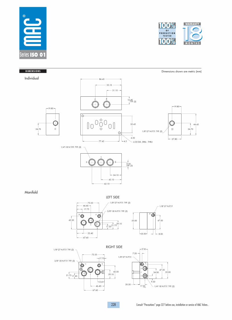
20.30
3/8"-18 N.P.T.F. TYP. (3)
3/8"-18 N.P.T.F. TYP. (3)
RIGHT SIDE
LEFT SIDE
55.0047.50
34.00
9.50
55.00 47.00
67.60
46.40
22.40
17.75
73.55
21.75 29.1017.20
43.50
43.50
21.7529.10
17.20
67.60
22.40
46.40
17.75
73.55
1/8"-27 N.P.T.F.
27.00
7.50
1/4"-18 N.P.T.F. TYP. (2)
1/8"-27 N.P.T.F
8.00
17.50
25.50
1/8"-27 N.P.T.F. TYP. (2)
1/8"-27 N.P.T.F. TYP. (2)
P
TYP.(2)
D I M E N S I O N S Dimensions shown are metric (mm)
1818100%100%
100%100% M O N T H S
WARRANTY
O FP R O D U C T I O N
T E S T E D
228 Consult “Precautions” page 327 before use, installation or service of MAC Valves..
Series ISO 01
1/8"-27 N.P.T.F. TYP. (2)
1/4"-18 N.T.P.F. TYP. (3)
35.45
4.50
4.577.45 4.30 DIA. DRILL - THRU
16.40
31.10
55.10
86.45
19.80
24.70
44.45
27.80
9.50
24.10
43.10
62.10
19.80
24.70
TYP. (2)
TYP. (3)
Individual
Manifold

B a s e s a c c o r d i n g t o I S O 1 5 4 0 7 9 / 1
H O W T O O R D E R
229 Consult “Precautions” page 327 before use, installation or service of MAC Valves..
ISO 01
ISO 02
ISO 1
ISO 2
ISO 3
Series
Series ISO 02
Port size
1/8” NPTF
Pilot air
Internal
Side ports
MB-A02A-111
Bottom 2 & 4 ports With all side ports
MB-A02A-112
INDIVIDUAL BASE
Port size
1/8” NPTF
Pilot air
Internal
Side ports
MM-A02A-111
Bottom 2 & 4 ports With side 1, 3 & 5 ports
MM-A02A-112
MANIFOLD BASE
Notes: - For manifold bases external pilot is common- A base is ordered as internal pilot and can be changed into external pilot by removing pipe plugs from the external pilot ports (individual base).- Manifold base: same base for internal and external pilot, different end plate kits.End plate kit: Internal pilot M-00018-01-01
External pilot M-00018-02-01Inlet/exhaust isolator: 28499
Non plug-in individual / manifold base
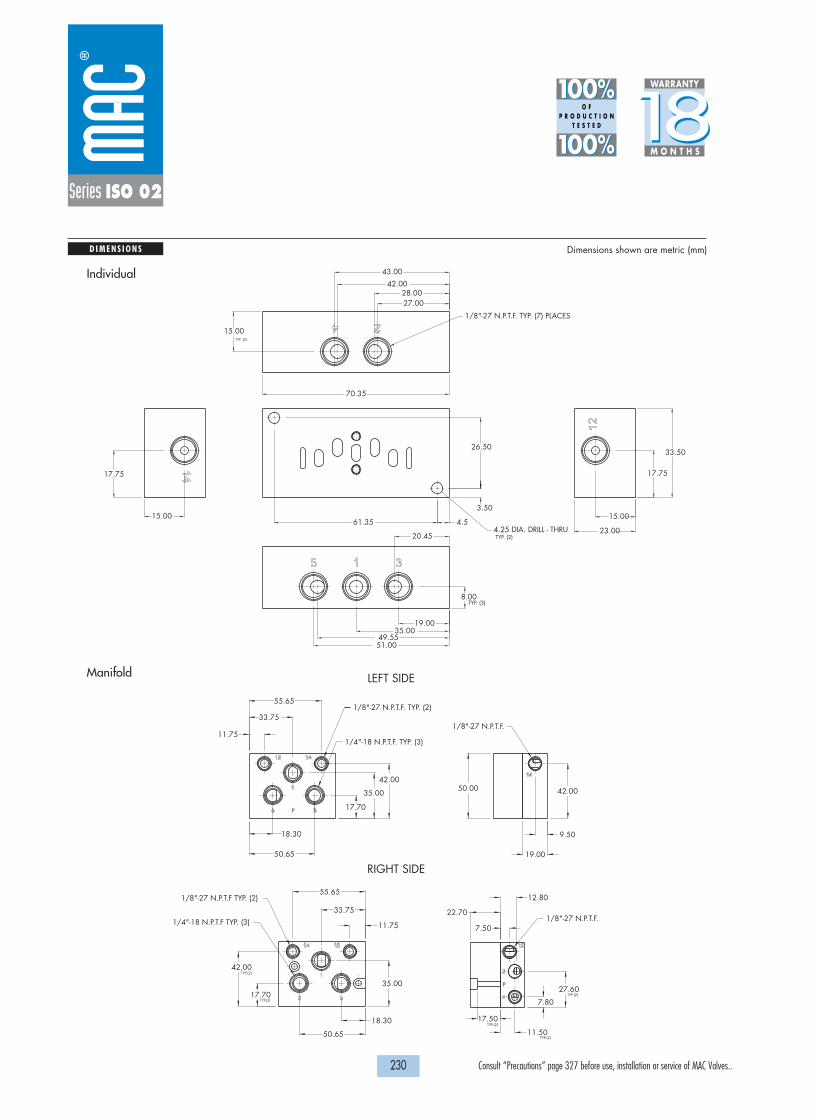
1/8"-27 N.P.T.F. TYP. (2)
1/8"-27 N.P.T.F TYP. (2)
1/4"-18 N.P.T.F. TYP. (3)
1/4"-18 N.P.T.F TYP. (3)
RIGHT SIDE
LEFT SIDE
1/8"-27 N.P.T.F.
50.00
50.65
42.00
1/8"-27 N.P.T.F.
27.60
7.80
7.50
12.80
11.50
42.00
9.50
19.00
17.70
35.00
11.75
33.75
55.65
18.30
11.75
55.65
33.75
18.30
50.65
17.70
42.00
35.00
22.70
17.50
TYP.(2)
TYP.(2)
P
P
TYP.(2)
TYP.(2)
TYP.(2)
D I M E N S I O N S Dimensions shown are metric (mm)
1818100%100%
100%100% M O N T H S
WARRANTY
O FP R O D U C T I O N
T E S T E D
230 Consult “Precautions” page 327 before use, installation or service of MAC Valves..
Series ISO 02
4.561.35
3.50
26.50
4.25 DIA. DRILL - THRU
15.00
27.00
43.00
42.0028.00
70.35
17.75
33.50
15.00
23.00
19.00
51.00
8.00
20.45
49.5535.00
17.75
15.00
1/8"-27 N.P.T.F. TYP. (7) PLACES
TYP. (2)
TYP. (2)
TYP. (3)
Individual
Manifold

B a s e s a c c o r d i n g t o I S O 5 5 9 9 / 1
H O W T O O R D E R
231 Consult “Precautions” page 327 before use, installation or service of MAC Valves..
ISO 01
ISO 02
ISO 1
ISO 2
ISO 3
Series
Series ISO 1
Series
Port size
1/4” NPTF
3/8” NPTF
Side ports
MB-A1C-221
MB-A1C-231
Side & bottom ports
MB-A1C-223
MB-A1C-233
Bottom cylinder ports 2 and 4.
MB-A1C-222
MB-A1C-232
Bottom inlet port 1
MB-A1C-224
MB-A1C-234
INDIVIDUAL BASE
Port size
1/4” NPTF
3/8” NPTF
Side ports
MM-A1C-221
MM-A1C-231
Side & bottom ports
MM-A1C-223
MM-A1C-233
Bottom cylinder ports 2 and 4.
MM-A1C-222
MM-A1C-232
Bottom inlet port 1
MM-A1C-224
MM-A1C-234
MANIFOLD BASE
Manifold fastening kit : N-63002-01.Valve blanking plate: MA1003.Inlet/exhaust isolator plug: 32835.
Non plug-in base / manifold

D I M E N S I O N S Dimensions shown are metric (mm)
1818100%100%
100%100% M O N T H S
WARRANTY
O FP R O D U C T I O N
T E S T E D
232 Consult “Precautions” page 327 before use, installation or service of MAC Valves..
Series ISO 1
42 513
26,0
32,5 40,0 42,5 50,5
16,0
26,0
121,0
26,0
25,0 25,0
14,0 22,0 26,0
100,0
100,0
2 4
3 51
68,0
13,06,0
50,0
50,07,5
85,0
12,0
11,0
13,0
14,0
9,0
62,0
36,0
DIN 5599/1
513
4
2
22,0 21,0 26,0
12,7525,5
100,060,0
6,0
18,0 24,7551,0± 0,2
121,0
Ø 6,5 2 MTG. HOLES
OPTIONALBOTTOM PORTS
OPTIONALBOTTOM PORTS
1/8” EXTERNAL PILOT
3/8” 3 PORTS
Ø 6,3 2 MTG. HOLES
1/8” EXTERNAL PILOT
Individual Manifold

B a s e s a c c o r d i n g t o I S O 5 5 9 9 / 1
H O W T O O R D E R
233 Consult “Precautions” page 327 before use, installation or service of MAC Valves..
ISO 01
ISO 02
ISO 1
ISO 2
ISO 3
Series
Series ISO 1
Series
Port size
1/4” NPTF
3/8” NPTF
Wired for
Single solenoid
Double solenoid
Single solenoid
Double solenoid
Side ports
MB-P1A-221-A
MB-P1A-221-B
MB-P1A-231-A
MB-P1A-231-B
Side ports w/ bottom 2 & 4 ports
MB-P1A-222-A
MB-P1A-222-B
MB-P1A-232-A
MB-P1A-232-B
All side & bottom ports
MB-P1A-223-A
MB-P1A-223-B
MB-P1A-233-A
MB-P1A-233-B
Port size
1/4” NPTF
3/8” NPTF
Wired for
Single solenoid
Double solenoid
Single solenoid
Double solenoid
Side ports
MM-P1A-221-A
MM-P1A-221-B
MM-P1A-231-A
MM-P1A-231-B
Side ports w/ bottom 2 & 4 ports
MM-P1A-222-A
MM-P1A-222-B
MM-P1A-232-A
MM-P1A-232-B
All side & bottom ports(see note)
MM-P1A-223-A
MM-P1A-223-B
MM-P1A-233-A
MM-P1A-233-B
INDIVIDUAL BASE
MANIFOLD BASE
Accessories: M-P1001 Valve blanking plate.N-P1007-01 Manifold fastening kit.32835 Inlet/exhaust isolator plug.
Plug-in base / manifold
MM-P1A-22X-X
O P T I O N S
25 for 1/4" port – common external pilot26 for 3/8" port – common external pilot
MM-P1A-XXX-A
J wired for sgl solenoidK wired for double solenoid
MX-P1A-XXX-XJA
JA 110/120 voltJB 220/240 voltDA 24 volt
Manifold options :
Base / Manifold option: light(s)
External pilot
Terminal strip(N/A with light)
Note : Ports 1, 3 & 5 are always 3/8”

D I M E N S I O N S Dimensions shown are metric (mm)
1818100%100%
100%100% M O N T H S
WARRANTY
O FP R O D U C T I O N
T E S T E D
234 Consult “Precautions” page 327 before use, installation or service of MAC Valves..
Series ISO 1
Ø 6.3 TYP (2)
PORTSOPTIONAL BOTTOM
CONDUIT1/2" NPSM
111.3
56.345.7
17.8
36.2
5.3
38.6
77.457.5
13.633.5
100.2
105.569.5
45.521.5
25.823.3
15.815.3
16.0
107.8
67.3
57.5
45.5
33.5
22.7
147.5
P
1
35
32145
14
(2) MTG HOLESØ 6.3 THRU
PORTSOPTIONAL BOTTOM
EXTERNAL PILOT 1/8"OPTIONAL COMMON
TYP(3)3/8" COMMONS
CONDUIT1" NPSM
52.0
40.0
28.013.7
13.0
52.032.0
28.015.5
90.5 15.9
90.3
70.7
46.2
25.4
15.0 42.0
15.0
12.024.0
159.3
115.2
132.8
92.0
90.7
65.5
38.5
20.2
108.5
41.0
32.226.0
6.9
127.0
40.529.7
32.220.91
5
3
COND
4
12
42
2
1
3
5
Individual
Manifold

B a s e s a c c o r d i n g t o I S O 5 5 9 9 / 1
H O W T O O R D E R
235 Consult “Precautions” page 327 before use, installation or service of MAC Valves..
ISO 01
ISO 02
ISO 1
ISO 2
ISO 3
Series
Series ISO 2
Series
Port size
3/8” NPTF
1/2” NPTF
Side ports
MB-A2B-221
MB-A2B-231
Bottom ports
MB-A2B-223
MB-A2B-233
Bottom cylinder ports 2 and 4.
MB-A2B-222
MB-A2B-232
Bottom inlet port 1
MB-A2B-224
MB-A2B-234
INDIVIDUAL BASE
Port size
3/8” NPTF
1/2” NPTF
Side ports
MM-A2B-221
MM-A2B-231
Bottom ports
MM-A2B-223
MM-A2B-233
Bottom cylinder ports 2 and 4.
MM-A2B-222
MM-A2B-232
Bottom inlet port 1
MM-A2B-224
MM-A2B-234
MANIFOLD BASE
Manifold fastening kit : N-63002-01.Valve blanking plate: MA2003.Inlet/exhaust isolator plug: 32839.
Non plug-in base / manifold

D I M E N S I O N S Dimensions shown are metric (mm)
1818100%100%
100%100% M O N T H S
WARRANTY
O FP R O D U C T I O N
T E S T E D
236 Consult “Precautions” page 327 before use, installation or service of MAC Valves..
Series ISO 2
3 1 5
2 4
4
3
2 1
5
26,0
112,0
139,0
9,0
30,552,0
64,0± 0,2
7,014,014,5
32,0 30,0
23,0 34,0
70,0
34,0 34,0
39,0 42,050,5
38,0
32,060,0
88,036,0
16,0
62,0
12,0
62,0
16,0
10,0
75,0
98,07,0
112,0
23,0 32,0 42,0 49,062,1
54,020,0
2 4
531
DIN 5599/1
OPTIONALBOTTOM PORTS
Ø 7,5 2 MTG. HOLES
OPTIONALBOTTOM PORTS
1/8” EXTERNAL PILOT
1/2”-3 PORTSEACH SIDE
Ø 6,5 2 MTG. HOLES
1/8” EXTERNAL PILOT
Individual Manifold

B a s e s a c c o r d i n g t o I S O 5 5 9 9 / 1
H O W T O O R D E R
237 Consult “Precautions” page 327 before use, installation or service of MAC Valves..
ISO 01
ISO 02
ISO 1
ISO 2
ISO 3
Series
Series ISO 2
Series
Port size
3/8” NPTF
1/2” NPTF
Wired for
Single solenoid
Double solenoid
Single solenoid
Double solenoid
Side ports
MB-P2A-221-A
MB-P2A-221-B
MB-P2A-231-A
MB-P2A-231-B
Side ports w/ bottom 2 & 4 ports
MB-P2A-222-A
MB-P2A-222-B
MB-P2A-232-A
MB-P2A-232-B
All side & bottom ports
MB-P2A-223-A
MB-P2A-223-B
MB-P2A-233-A
MB-P2A-233-B
Port size
3/8” NPTF
1/2” NPTF
Wired for
Single solenoid
Double solenoid
Single solenoid
Double solenoid
Side ports
MM-P2A-221-A
MM-P2A-221-B
MM-P2A-231-A
MM-P2A-231-B
Side ports w/ bottom 2 & 4 ports
MM-P2A-222-A
MM-P2A-222-B
MM-P2A-232-A
MM-P2A-232-B
All side & bottom ports(see note)
MM-P2A-223-A
MM-P2A-223-B
MM-P2A-233-A
MM-P2A-233-B
INDIVIDUAL BASE
MANIFOLD BASE
Accessories: M-P2001 Valve blanking plate.N-P2004-01 Manifold fastening kit.32839 Inlet/exhaust isolator plug.
Plug-in base / manifold
MM-P2A-22X-X
O P T I O N S
25 for 3/8" port – common external pilot26 for 1/2" port – common external pilot
MM-P2A-XXX-A
J wired for sgl solenoidK wired for double solenoid
MX-P2A-XXX-XJA
JA 110/120 voltJB 220/240 voltDA 24 volt
Manifold options :
Base / Manifold option: light(s)
External pilot
Terminal strip(N/A with light)
Note : Ports 1, 3 & 5 are always 1/2”

D I M E N S I O N S Dimensions shown are metric (mm)
1818100%100%
100%100% M O N T H S
WARRANTY
O FP R O D U C T I O N
T E S T E D
238 Consult “Precautions” page 327 before use, installation or service of MAC Valves..
Series ISO 2
173.8
34.0
B
PORTSOPTIONAL BOTTOM
CONDUIT1/2" N.P.S.M.
(2)MTG HOLES6.5 DIA. THRU
54.50
5.5
#14#12
22.0 24.5
PILOT 1/8"#14 EXTERNAL
34.5 34.5
PILOT 1/8"#12 EXTERNAL
119.25 5.5
SINGLE SOLENOID
DOUBLE SOLENOID
146.8
22.0
125.0
55.0
AC
G
F
E
65.5
17.0
48.5
81.0
51.0
20.5
43.5
40.0
70.0
140.0
1
3
2 4
5
115.9
156.1
42
COND
3
5
1
5
1
3
42
SIDE CYL.CENT. OF 1/2"
SIDE CYL.CENT. OF 3/8"
SOLENOIDSINGLE & DOUBLE 187.0
18.3 105.5
50.0 39.5
38.0
37.0
19.0 17.5
11.3
35.5
71.5
103.0
26.0 30.0
38.0
103.0
45.0
22.0
15.0
30.0
45.0
77.0
168.00 5.50
45.0
60.0
(2)MTG HOLES6.5 DIA. THRU
18.5
#14
PILOT 1/8"#14 EXTERNAL
#12
18.0
8.5
50.0
41.5
134.1PILOT 1/8"#12 EXTERNAL
CONDUIT1-1/4" N.P.S.M.EXTERNAL PILOT 1/8"
OPTIONAL COMMON
PORTSOPTIONAL BOTTOM
51.0
6.0
Individual
Manifold
Dim
3/8” NPTF
1/2” NPTF
A
25.2
24.0
B
22.7
21.0
C
20.6
19.0
D
26.7
25.5
E
40.5
40.0
F
69.4
70.0
G
83.3
84.5
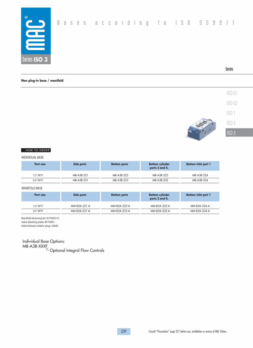
B a s e s a c c o r d i n g t o I S O 5 5 9 9 / 1
HOW TO ORDER
239 Consult “Precautions” page 327 before use, installation or service of MAC Valves..
ISO 01
ISO 02
ISO 1
ISO 2
ISO 3
Series ISO 3Series
Port size
1/2” NPTF
3/4” NPTF
Side ports
MB-A3B-221
MB-A3B-231
Bottom ports
MB-A3B-223
MB-A3B-233
Bottom cylinder ports 2 and 4.
MB-A3B-222
MB-A3B-232
Bottom inlet port 1
MB-A3B-224
MB-A3B-234
INDIVIDUAL BASE
Port size
1/2” NPTF
3/4” NPTF
Side ports
MM-B3A-221-A
MM-B3A-231-A
Bottom ports
MM-B3A-223-A
MM-B3A-233-A
Bottom cylinder ports 2 and 4.
MM-B3A-222-A
MM-B3A-232-A
Bottom inlet port 1
MM-B3A-224-A
MM-B3A-234-A
MANIFOLD BASE
Manifold fastening kit: N-P3003-01.Valve blanking plate: M-P3001.Inlet/exhaust isolator plug: 32845.
Non plug-in base / manifold
Individual Base Options: MB-A3B-XXXF
Optional Integral Flow Controls

D I M E N S I O N S Dimensions shown are metric (mm)
1818100%100%
100%100% M O N T H S
WARRANTY
O FP R O D U C T I O N
T E S T E D
240 Consult “Precautions” page 327 before use, installation or service of MAC Valves..
Series ISO 3
2 4
12 14 2
31
4
546,0
45,0
22,043,5
55,0
140,0
70,0
35,0
15,0
15,0
32,0
21,0
64,0
49,0 49,0
39,5
79,0
78,0
156,0
17,5
45,0
20,5 20,5
49,049,0
33,0 27,0
ISO DIN 5599/1
OPTIONAL BOTTOMPORTS
Ø 8,3 4 MTG. HOLES
1/8” EXTERNAL PILOT/REMOTE AIR PILOT PORT (2 PLACES)
Individual
Manifold
26.5
50.077,9
23.02 4
12
19.0 40.0
P
31.0
33.4 27.0
59.0
39.0 19.0
208.0 9.0 55.7
99.9
136.4
25.8
5
13
24
188.9175.2
162.0140.0
96.0 50.2
17.3
232.1
3
5
1
COND
32.8 48.8
65.8
27.8 48.0
47.0 63.3
78.0
2 MTG HOLES8.25 DIA. THRU

B a s e s a c c o r d i n g t o I S O 5 5 9 9 / 1
H O W T O O R D E R
241 Consult “Precautions” page 327 before use, installation or service of MAC Valves..
ISO 01
ISO 02
ISO 1
ISO 2
ISO 3
Series
Series ISO 3
Series
Port size
1/2” NPTF
3/4” NPTF
Wired for
Single solenoid
Double solenoid
Single solenoid
Double solenoid
Side ports
MM-P3A-221-A
MM-P3A-221-B
MM-P3A-231-A
MM-P3A-231-B
Side ports w/ bottom 2 & 4 ports
MM-P3A-222-A
MM-P3A-222-B
MM-P3A-232-A
MM-P3A-232-B
All side & bottom ports(see note)
MM-P3A-223-A
MM-P3A-223-B
MM-P3A-233-A
MM-P3A-233-B
MANIFOLD BASE
Accessories: M-P3001 Valve blanking plate.N-P3003-01 Manifold fastening kit.32845 Inlet/exhaust isolator plug.
Plug-in manifold
MM-P3A-22X-X
O P T I O N S
25 for 1/2" port – common external pilot26 for 3/4" port – common external pilot
MM-P3A-XXX-A
J wired for sgl solenoidK wired for double solenoid
MM-P3A-XXX-XJA
JA 110/120 voltJB 220/240 voltDA 24 volt
Manifold options :
light(s)
External pilot
Terminal strip
Note : Ports 1, 3 & 5 are always 3/4”
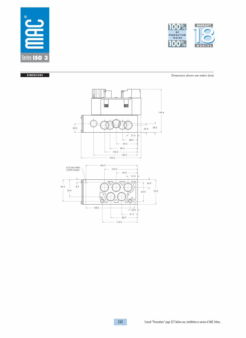
D I M E N S I O N S Dimensions shown are metric (mm)
1818100%100%
100%100% M O N T H S
WARRANTY
O FP R O D U C T I O N
T E S T E D
242 Consult “Precautions” page 327 before use, installation or service of MAC Valves..
Series ISO 3
79.0
166.5
158.0
114.0
86.5 51.5
24.0
107.0
69.0
31.0
54.5
69.5
8.25 DIA THRU2 MTG HOLES
62.0
24.5
8.5
142.0106.5
89.5
69.0
48.5
31.0
193.0
139.4
28.5 29.0 23.5
AU
CK
LAN
D,N
.Z.
LIE
GE
,BE
LGIU
MW
IXO
M,M
I. U
SA
MO
DIF
.
MO
DE
L
ELE
CT
RIC
AL
WA
TT
S
VA
C T
O 1
20 P
SI
4
5 3
2
1
14 12

243 Consult “Precautions” page 327 before use, installation or service of MAC Valves..
S e c t i o n 4 Pressure regu la tors

245 Consult “Precautions” page 327 before use, installation or service of MAC Valves..
P r e s s u r e r e g u l a t o r s
Sandwich pressure regulator with manual adjust knob
Sandwich pressure regulator with manual adjust knob
Sandwich pressure regulator
Sandwich pressure regulator with manual adjust knob
Sandwich pressure regulator with manual adjust knob
Sandwich pressure regulator with air pilot adjust
Sandwich pressure regulator with manual adjust knob
Sandwich pressure regulator with manual adjust knob
Sandwich pressure regulator with air pilot adjust
Sandwich pressure regulator with manual adjust knob
Sandwich pressure regulator with manual adjust knob
Non plug-in sandwich pressure regulator with manual adjust
Plug-in sandwich pressure regulator with air pilot adjust
Non plug-in sandwich pressure regulator with manual adjust
Non plug-in sandwich pressure regulator with manual adjust knob
Non plug-in sandwich pressure regulator with air pilot adjust
Plug-in sandwich pressure regulator with manual adjust knob
Plug-in sandwich pressure regulator with air pilot adjust
Non plug-in sandwich pressure regulator with manual adjust knob
Non plug-in sandwich pressure regulator with air pilot adjust
Plug-in sandwich pressure regulator with manual adjust knob
Plug-in sandwich pressure regulator with air pilot adjust
Non plug-in sandwich pressure regulator with manual adjust knob
Non plug-in sandwich pressure regulator with air pilot adjust
Plug-in sandwich pressure regulator with manual adjust knob
Plug-in sandwich pressure regulator with air pilot adjust
P. 247
P. 249
P. 251
P. 253
P. 255
P. 257
P. 259
P. 261
P. 263
P. 265
P. 267
P. 269
P. 271
P. 273
P. 275
P. 277
P. 279
P. 281
P. 283
P. 285
P. 287
P. 289
P. 291
P. 293
P. 295
P. 297
Series
PR37APR42BPR46APR47APR48B
PRA02A
PR92C
PR93A
PRA1A
PRA01A
PRP1A
PRA2D
PRP2B
PRA3C
PRP3B

H O W T O O R D E R
247 Consult “Precautions” page 327 before use, installation or service of MAC Valves..
P r e s s u r e r e g u l a t o r s
OPERATIONAL BENEFITS
Series
PR37APR42BPR46APR47APR48B
PRA02A
PR92C
PR93A
PRA1A
PRA01A
PRP1A
PRA2D
PRP2B
PRA3C
PRP3B
Series PR37A
Sandwich pressure regulator with manual adjust knob
1. Easy mounting: saves on installation costs incomparison with inline regulators.
2. Compact all-included units.3. Large orifice provides high flow.4. Various functions available.5. Simple, reliable and solid design.
Gage
No gage port
With gage Port (plugged)
Single pressure
PR37A-FAAA
PR37A-FABA
REGULATORS FOR "NON PLUG-IN" VALVES (CODED FOR KNOB ADJUSTMENT)
Note: Regulating pressure range for above models is 0 to 120 PSIFor other ranges, see below.
PR37A-FXXX
OPTIONS
B for slotted stemK for slotted stem with locknut
Adjustment :
PR37A-XXXA
B for 0 to 80 PSIC for 0 to 30 PSI
Pressure range :

1818100%100%
100%100% M O N T H S
WARRANTY
O FP R O D U C T I O N
T E S T E D
D I M E N S I O N S
T E C H N I C A L D A T A
Dimensions shown are metric (mm)
248 Consult “Precautions” page 327 before use, installation or service of MAC Valves..
F
E98.4
APPROX
APPROX
APPROX
84.3
102.8
Series PR37A
Fluid :
Pressure range :
Regulating range :
Lubrication :
Filtration :
Temperature range :
Flow :
Compressed air, inert gases
0 to 120 PSI
0 to 120 PSI
Not required, if used select a medium aniline point lubricant (between 180°F to 210°F)
40 µ
0°F to 120°F (-18°C to +50°C)
0.4 Cv
• Pressure regulator (less sandwich block) : PR37A-G0AA (knob), PR37A-C0AA (slotted stem), PR37A-L0AA (slotted stem with locknut)
• Gages : 24177-160 (0 to 160 PSI, 23 mm)24177-100 (0 to 100 PSI, 23 mm)24177-060 (0 to 60 PSI, 23 mm)
Spare parts :

H O W T O O R D E R
249 Consult “Precautions” page 327 before use, installation or service of MAC Valves..
P r e s s u r e r e g u l a t o r s
OPERATIONAL BENEFITS
Series
PR37APR42BPR46APR47APR48B
PRA02A
PR92C
PR93A
PRA1A
PRA01A
PRP1A
PRA2D
PRP2B
PRA3C
PRP3B
Series PR42B
Sandwich pressure regulator with manual adjust knob
1. Easy mounting: saves on installation costs incomparison with inline regulators.
2. Compact all-included units.3. Large orifice provides high flow.4. Various functions available.5. Simple, reliable and solid design.
OPTIONS
Notes:- External pilot regulator required only when supply pressure (primary) to the valve is below theminimum operating pressure of the 42 series valve.- When an internal pilot regulator is used with the 42 series valve, the valve should be orderedas external pilot and the base should be ordered as internal pilot. This ensures that the pilotsupply is not regulated. If an internal pilot valve and base are used with an internal pilotregulator, the pilot supply is regulated.
Example: Valve 42B-AM D -AA A -GxxP-xxx with PR42B-AAAA
PR42B-AAAA
A 0 to 120 PSIB 0 to 80 PSIC 0 to 40 PSI
Pressure range :
External pilot option in valve
Internal pilot option in base
Gage
No gage port
With gage Port
Regulator "12” end Internal pilot
PR42B-BAAA
PR42B-BABA
Regulator "12” end External pilot
PR42B-BBAA
PR42B-BBBA
NON PLUG-IN SANDWICH REGULATORS
Gage
No gage port
With gage Port
Regulator "12” end Internal pilot
PR42B-AAAA
PR42B-AABA
Regulator "12” end External pilot
PR42B-ABAA
PR42B-ABBA
PLUG-IN SANDWICH REGULATORS

1818100%100%
100%100% M O N T H S
WARRANTY
O FP R O D U C T I O N
T E S T E D
D I M E N S I O N S
T E C H N I C A L D A T A
Dimensions shown are metric (mm)
250 Consult “Precautions” page 327 before use, installation or service of MAC Valves..
Series PR42B
Fluid :
Pressure range :
Regulating range :
Lubrication :
Filtration :
Temperature range :
Flow :
Compressed air, inert gases
0 to 120 PSI
0 to 120 PSI
Not required, if used select a medium aniline point lubricant (between 180°F to 210°F)
40 µ
0°F to 120°F (-18°C to +50°C)
0.25 Cv
166.6
180.6
- +
L
O C K
- +
L
O C K
- +
L
O C K
- +
L
O C K
2
4
2
44
2
4
2
X
53
1
101.7
3
1
5
113.2
• Pressure regulator (less sandwich block) : PR42B-C0xx • Gage port plug: N-PE003• #10 -32 to 1/8” adapter : N-35005 • Gage: 24177-160 (0 to 160 PSI, 23 mm)
24177-100 (0 to 100 PSI, 23 mm)24177-060 (0 to 60 PSI, 23 mm)
Spare parts :
NON PLUG-IN
PLUG-IN

H O W T O O R D E R
251 Consult “Precautions” page 327 before use, installation or service of MAC Valves..
P r e s s u r e r e g u l a t o r s
OPERATIONAL BENEFITS
Series
Series PR46A
Sandwich-pressure regulator
1. Easy mounting: saves on installation costs incomparison with inline regulators.
2. Compact all included units.3. Large orifice provides high flow.4. Various functions available.5. Simple, reliable and solid design.6. Single pressure regulator.
OPTIONS
PR46A-AAA A
A 0 to 120 PSIB 0 to 80 PSIC 0 to 30 PSI
Pressure range :
A Manual adjust with slotted screwdriver stemB Manual adjust with adjusting knobC Manual adjust with slotted screwdriver stem and locknut
Gauge
Gauge port (plugged)
For plug-in valves
PR46A-AAAA
For non plug-in valves
PR46A-BAAA
REGULATORS FOR "PLUG-IN" AND "NON PLUG-IN" VALVES
PR37APR42BPR46APR47APR48B
PRA02A
PR92C
PR93A
PRA1A
PRA01A
PRP1A
PRA2D
PRP2B
PRA3C
PRP3B
0 Regulator only (No sandwich block)
Notes : gadges must be ordered separately, not included with regulator.Recommended gage : 24165-150 (15 mm)

1818100%100%
100%100% M O N T H S
WARRANTY
O FP R O D U C T I O N
T E S T E D
D I M E N S I O N S
T E C H N I C A L D A T A
Dimensions shown are metric (mm)
252 Consult “Precautions” page 327 before use, installation or service of MAC Valves..
Series PR46A
Fluid :
Pressure range :
Regulating range :
Lubrication :
Filtration :
Temperature range :
Flow :
Compressed air, inert gases
0 to 120 PSI
0 to 120 PSI
Not required, if used select a medium aniline point lubricant (between 180°F and 210°F)
40 µ
0°F to 120°F (-18°C to +50°C)
Cv 0,21
105.2
32.8
147.1
1/4" COMMONS
1/4" COMMONS
1"-11 1/2 NPS
82.5
32.9103.1
IN
IN
EXH
EXH
CO
ND
72.4 72.8
NON PLUG-IN PLUG-IN

H O W T O O R D E R
253 Consult “Precautions” page 327 before use, installation or service of MAC Valves..
P r e s s u r e r e g u l a t o r s
OPERATIONAL BENEFITS
Series
PR37APR42BPR46APR47APR48B
PRA02A
PR92C
PR93A
PRA1A
PRA01A
PRP1A
PRA2D
PRP2B
PRA3C
PRP3B
Series PR47A
1. Easy mounting: saves on installation costs incomparison with inline regulators.
2. Compact all-included units.3. Large orifice provides high flow.4. Various functions available.5. Simple, reliable and solid design.
Sandwich pressure regulator with manual adjust knob
Gage
No gage port
With gage Port
Single pressure
PR47A-EAAA
PR47A-EABA
REGULATORS FOR "PLUG-IN" VALVES (KNOB ADJUSTMENT)
PR47A-EXXX
OPTIONS
E KnobA Screwdriver slotJ Screwdriver slot with locknut
Adjustment for : Plug-in regulator Non plug-in regulator
PR47A-FXXX
F KnobB Screwdriver slotK Screwdriver slot with locknut
PR47A-XXXA
A 0 to 120 PSIB 0 to 80 PSIC 0 to 30 PSI
Pressure range :
Gage
No Gage port
With Gage Port
Single pressure
PR47A-FAAA
PR47A-FABA
REGULATORS FOR "NON PLUG-IN" VALVES (KNOB ADJUSTMENT)

200.8
3
1
5
P
112.7
1818100%100%
100%100% M O N T H S
WARRANTY
O FP R O D U C T I O N
T E S T E D
D I M E N S I O N S
T E C H N I C A L D A T A
Dimensions shown are metric (mm)
254 Consult “Precautions” page 327 before use, installation or service of MAC Valves..
Series PR47A
Fluid :
Pressure range :
Regulating range :
Lubrication :
Filtration :
Temperature range :
Flow :
Compressed air, inert gases
0 to 120 PSI
0 to 120 PSI
Not required, if used select a medium aniline point lubricant (between 180°F to 210°F)
40 µ
0°F to 120°F (-18°C to +50°C)
0.4 Cv
• Pressure regulator (less sandwich block) : PR47A-G0AA (knob), PR47A-C0AA (screwdriver slot), PR47A-L0AA (screwdriver slot with locknut)• Gage: 24177-160 (0 to 160 PSI, 23 mm)
24177-100 (0 to 100 PSI, 23 mm)24177-060 (0 to 60 PSI, 23 mm)
Spare parts :
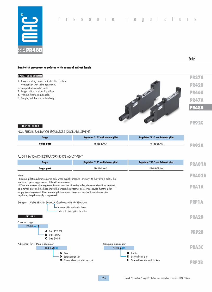
H O W T O O R D E R
255 Consult “Precautions” page 327 before use, installation or service of MAC Valves..
P r e s s u r e r e g u l a t o r s
OPERATIONAL BENEFITS
Series
PR37APR42BPR46APR47APR48B
PRA02A
PR92C
PR93A
PRA1A
PRA01A
PRP1A
PRA2D
PRP2B
PRA3C
PRP3B
Series PR48B
Sandwich pressure regulator with manual adjust knob
1. Easy mounting: saves on installation costs incomparison with inline regulators.
2. Compact all-included units.3. Large orifice provides high flow.4. Various functions available.5. Simple, reliable and solid design.
Gage
Gage port
Regulator "12” end Internal pilot
PR48B-BAAA
Regulator "12” end External pilot
PR48B-BBAA
NON PLUG-IN SANDWICH REGULATORS (KNOB ADJUSTMENT)
PR48B-AXXX
OPTIONS
A KnobD Screwdriver slotG Screwdriver slot with locknut
Adjustment for : Plug-in regulator Non plug-in regulator
PR48B-BXXX
B KnobE Screwdriver slotH Screwdriver slot with locknut
PR48B-XXXA
A 0 to 120 PSIB 0 to 80 PSIC 0 to 30 PSI
Pressure range :
Gage
Gage port
Regulator "12” end Internal pilot
PR48B-AAAA
Regulator "12” end External pilot
PR48B-ABAA
PLUG-IN SANDWICH REGULATORS (KNOB ADJUSTMENT)
Notes:- External pilot regulator required only when supply pressure (primary) to the valve is below theminimum operating pressure of the 48 series valve.- When an internal pilot regulator is used with the 48 series valve, the valve should be orderedas external pilot and the base should be ordered as internal pilot. This ensures that the pilotsupply is not regulated. If an internal pilot valve and base are used with an internal pilotregulator, the pilot supply is regulated.
Example: Valve 48B-AM D -AA A -GxxP-xxx with PR48B-AAAA
External pilot option in valve
Internal pilot option in base

1818100%100%
100%100% M O N T H S
WARRANTY
O FP R O D U C T I O N
T E S T E D
D I M E N S I O N S
T E C H N I C A L D A T A
Dimensions shown are metric (mm)
256 Consult “Precautions” page 327 before use, installation or service of MAC Valves..
Series PR48B
Fluid :
Pressure range :
Regulating range :
Lubrication :
Filtration :
Temperature range :
Flow :
Compressed air, inert gases
0 to 120 PSI
0 to 120 PSI
Not required, if used select a medium aniline point lubricant (between 180°F to 210°F)
40 µ
0°F to 120°F (-18°C to +50°C)
0.8 Cv
2
44
222
4 4
3
5
1
EP
COND
1
35EP
134.0
144.5
226.4
212.3
• Pressure regulator (less sandwich block) : PR48B-C0AA (knob), PR48B-F0AA (screwdriver slot), PR48B-J0AA (screwdriver slot with locknut)• Gage: 24177-160 (0 to 160 PSI, 23 mm)
24177-100 (0 to 100 PSI, 23 mm)24177-060 (0 to 60 PSI, 23 mm)
Spare parts :
NON PLUG-IN
PLUG-IN
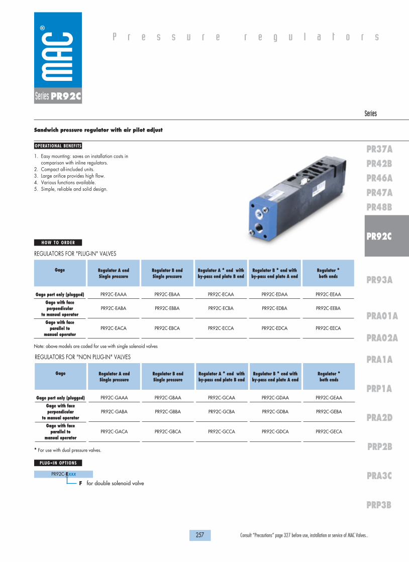
H O W T O O R D E R
257 Consult “Precautions” page 327 before use, installation or service of MAC Valves..
P r e s s u r e r e g u l a t o r s
OPERATIONAL BENEFITS
Series
PR37APR42BPR46APR47APR48B
PRA02A
PR92C
PR93A
PRA1A
PRA01A
PRP1A
PRA2D
PRP2B
PRA3C
PRP3B
Series PR92C
Sandwich pressure regulator with air pilot adjust
1. Easy mounting: saves on installation costs incomparison with inline regulators.
2. Compact all-included units.3. Large orifice provides high flow.4. Various functions available.5. Simple, reliable and solid design.
Gage
Gage port only (plugged)
Gage with faceperpendicular
to manual operator
Gage with face parallel to
manual operator
Regulator A end Single pressure
PR92C-EAAA
PR92C-EABA
PR92C-EACA
Regulator B end Single pressure
PR92C-EBAA
PR92C-EBBA
PR92C-EBCA
Regulator A * end with by-pass end plate B end
PR92C-ECAA
PR92C-ECBA
PR92C-ECCA
Regulator B * end withby-pass end plate A end
PR92C-EDAA
PR92C-EDBA
PR92C-EDCA
Regulator *both ends
PR92C-EEAA
PR92C-EEBA
PR92C-EECA
REGULATORS FOR "PLUG-IN" VALVES
PR92C-EXXX
PLUG-IN OPTIONS
F for double solenoid valve
Note: above models are coded for use with single solenoid valves
* For use with dual pressure valves.
Gage
Gage port only (plugged)
Gage with faceperpendicular
to manual operator
Gage with face parallel to
manual operator
Regulator A end Single pressure
PR92C-GAAA
PR92C-GABA
PR92C-GACA
Regulator B end Single pressure
PR92C-GBAA
PR92C-GBBA
PR92C-GBCA
Regulator A * end with by-pass end plate B end
PR92C-GCAA
PR92C-GCBA
PR92C-GCCA
Regulator B * end with by-pass end plate A end
PR92C-GDAA
PR92C-GDBA
PR92C-GDCA
Regulator *both ends
PR92C-GEAA
PR92C-GEBA
PR92C-GECA
REGULATORS FOR "NON PLUG-IN" VALVES

1818100%100%
100%100% M O N T H S
WARRANTY
O FP R O D U C T I O N
T E S T E D
D I M E N S I O N S
T E C H N I C A L D A T A
Dimensions shown are metric (mm)
258 Consult “Precautions” page 327 before use, installation or service of MAC Valves..
Series PR92C
Fluid :
Pressure range :
Regulating range :
Lubrication :
Filtration :
Temperature range :
Flow :
Compressed air, inert gases
0 to 120 PSI
0 to 120 PSI
Not required, if used select a medium aniline point lubricant (between 180°F to 210°F)
40 µ
0°F to 120°F (-18°C to +50°C)
0.8 Cv
EX
IN
VAC TO 120 PSI
WATTSELECTRICAL
MODEL
MODIF.
AUCKLAND,N.Z.LIEGE,BELGIUMWIXOM,MI. USA
EP
GAGE
PILOT
202.56
145.88
MANUALOPERATOR
W/ DOUBLE REGULATOR
APPROX.
APPROX. 47.5
APPROX.135.0
• R-92003 : regulator end plate kit • Gage kit 0 - 160 PSI: N-92006-01• R-92003-01: regulator by-pass end plate kit• Pressure regulator (less sandwich block) : PR92C-H0AA
Spare parts :

H O W T O O R D E R
259 Consult “Precautions” page 327 before use, installation or service of MAC Valves..
P r e s s u r e r e g u l a t o r s
OPERATIONAL BENEFITS
Series
PR37APR42BPR46APR47APR48B
PRA02A
PR92C
PR93A
PRA1A
PRA01A
PRP1A
PRA2D
PRP2B
PRA3C
PRP3B
Series PR92C
Sandwich pressure regulator with manual adjust knob
1. Easy mounting: saves on installation costs incomparison with inline regulators.
2. Compact all-included units.3. Large orifice provides high flow.4. Various functions available.5. Simple, reliable and solid design.
Gage
No Gage
Gage with faceperpendicular
to manual operator
Gage with face parallel to
manual operator
Regulator A end Single pressure
PR92C-JAAA
PR92C-JABA
PR92C-JACA
Regulator B end Single pressure
PR92C-JBAA
PR92C-JBBA
PR92C-JBCA
Regulator A * end with by-pass end plate B end
PR92C-JCAA
PR92C-JCBA
PR92C-JCCA
Regulator B * end with by-pass end plate A end
PR92C-JDAA
PR92C-JDBA
PR92C-JDCA
Regulator *both ends
PR92C-JEAA
PR92C-JEBA
PR92C-JECA
REGULATORS FOR “PLUG-IN” VALVES (CODED FOR KNOB ADJUSTMENT)
Note: above models are coded for use with single solenoid valves
PR92C-X0XX
OPTIONS
M KnobD Slotted stemS Slotted stem with locknut
Regulator less sandwich blockPR92C-XXXXX
A Slotted stem, single solenoidB Slotted stem, double solenoidC Slotted stem, non plug-inK Knob, double solenoidN Slotted stem w/ locknut, single solenoidP Slotted stem w/ locknut, double solenoidR Slotted stem w/ locknut, non plug-in
Other adjustment
Gage
No Gage
Gage with faceperpendicular
to manual operator
Gage with face parallel to
manual operator
Regulator A end Single pressure
PR92C-LAAA
PR92C-LABA
PR92C-LACA
Regulator B end Single pressure
PR92C-LBAA
PR92C-LBBA
PR92C-LBCA
Regulator A * end with by-pass end plate B end
PR92C-LCAA
PR92C-LCBA
PR92C-LCCA
Regulator B * end with by-pass end plate A end
PR92C-LDAA
PR92C-LDBA
PR92C-LDCA
Regulator *both ends
PR92C-LEAA
PR92C-LEBA
PR92C-LECA
REGULATORS FOR “NON PLUG-IN” VALVES (CODED FOR KNOB ADJUSTMENT)
* For use with dual pressure valves.Notes: - Regulating range for above models is 0 to 120 PSI. For other ranges, see technical data page.

1818100%100%
100%100% M O N T H S
WARRANTY
O FP R O D U C T I O N
T E S T E D
D I M E N S I O N S
T E C H N I C A L D A T A
Dimensions shown are metric (mm)
260 Consult “Precautions” page 327 before use, installation or service of MAC Valves..
Series PR92C
Fluid :
Pressure range :
Regulating range :
Lubrication :
Filtration :
Temperature range :
Flow :
Compressed air, inert gases
0 to 120 PSI
0 to 120 PSI
Not required, if used select a medium aniline point lubricant (between 180°F to 210°F)
40 µ
0°F to 120°F (-18°C to +50°C)
0.8 Cv
EX
IN
VAC TO 120 PSI
WATTSELECTRICAL
MODEL
MODIF.
AUCKLAND,N.Z.LIEGE,BELGIUMWIXOM,MI. USA
171.5
W/ DOUBLE REGULATORAPPROX.
241.0
EP
GAGE
PILOT
APPROX. 47.5
APPROX.135.0
MANUALOPERATOR
• R-92003 : end plate kit • R-92003-01: by-pass end plate kit • Gage kit 0 – 160 PSI : N-92006-01 • Gage kit 0 – 100 PSI : N-92006-02• Gage kit 0 – 60 PSI : N-92006-03
• Pressure range: PR92C-xxxA (A 0 to 120 PSI)
B 0 to 80 PSIC 0 to 30 PSID 0 to 120 PSI “A” end, 0 to 80 PSI “B” endE 0 to 120 PSI “B” end, 0 to 80 PSI “A” endF 0 to 120 PSI “A” end, 0 to 30 PSI “B” endG 0 to 120 PSI “B” end, 0 to 30 PSI “A” endH 0 to 80 PSI “A” end, 0 to 30 PSI “B” endJ 0 to 80 PSI “B” end, 0 to 30 PSI “A” end
Spare parts :
Options:

H O W T O O R D E R
261 Consult “Precautions” page 327 before use, installation or service of MAC Valves..
P r e s s u r e r e g u l a t o r s
OPERATIONAL BENEFITS
Series
PR37APR42BPR46APR47APR48B
PRA02A
PR92C
PR93A
PRA1A
PRA01A
PRP1A
PRA2D
PRP2B
PRA3C
PRP3B
Series PR92C
Sandwich selector pressure regulator with manual adjust knob
1. Easy mounting: saves on installation costs incomparison with inline regulators.
2. Compact all-included units.3. Large orifice provides high flow.4. Various functions available.5. Simple, reliable and solid design.
Gage
No Gage
Gage with face perpendicular to manual operator
Gage with face parallel to
manual operator
Select to A port Regulator A end
By-pass plate B end
PR92C-JPAA
PR92C-JPBA
PR92C-JPCA
Select to B port Regulator B end
By-pass plate A end
PR92C-JRAA
PR92C-JRBA
PR92C-JRCA
Select to A port Reg. both ends A end low press. B end high press.
PR92C-JSAA
PR92C-JSBA
PR92C-JSCA
Select to B port Reg. both endsA end high press.B end low press.
PR92C-JTAA
PR92C-JTBA
PR92C-JTCA
REGULATORS FOR "PLUG-IN" VALVES (CODED FOR KNOB ADJUSTMENT)
Note: above models are coded for use with single solenoid valves
Notes: - Regulating range for above models is 0 to 120 PSI. For other ranges, see technical data page- Use single pressure valve for all above models.
Gage
No Gage
Gage with face perpendicular to manual operator
Gage with face parallel to
manual operator
Select to A port Regulator A end
By-pass plate B end
PR92C-LPAA
PR92C-LPBA
PR92C-LPCA
Select to B port Regulator B end
By-pass plate A end
PR92C-LRAA
PR92C-LRBA
PR92C-LRCA
Select to A port Reg. both ends A end low press. B end high press.
PR92C-LSAA
PR92C-LSBA
PR92C-LSCA
Select to B port Reg. both endsA end high press.B end low press.
PR92C-LTAA
PR92C-LTBA
PR92C-LTCA
REGULATORS FOR "NON PLUG-IN" VALVES (CODED FOR KNOB ADJUSTMENT)
PR92C-X0XX
OPTIONS
M KnobD Slotted stemS Slotted stem with locknut
Regulator less sandwich blockPR92C-XXXX
A Slotted stem, single solenoidB Slotted stem, double solenoidC Slotted stem, non plug-inK Knob, double solenoidN Slotted stem w/ locknut, single solenoidP Slotted stem w/ locknut, double solenoidR Slotted stem w/ locknut, non plug-in
Other adjustment
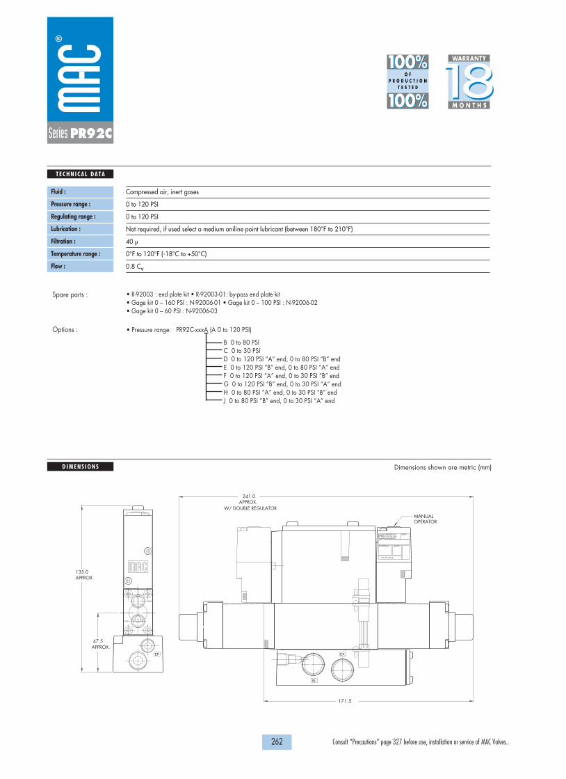
1818100%100%
100%100% M O N T H S
WARRANTY
O FP R O D U C T I O N
T E S T E D
D I M E N S I O N S
T E C H N I C A L D A T A
Dimensions shown are metric (mm)
262 Consult “Precautions” page 327 before use, installation or service of MAC Valves..
Series PR92C
Fluid :
Pressure range :
Regulating range :
Lubrication :
Filtration :
Temperature range :
Flow :
Compressed air, inert gases
0 to 120 PSI
0 to 120 PSI
Not required, if used select a medium aniline point lubricant (between 180°F to 210°F)
40 µ
0°F to 120°F (-18°C to +50°C)
0.8 Cv
EX
IN
VAC TO 120 PSI
WATTSELECTRICAL
MODEL
MODIF.
AUCKLAND,N.Z.LIEGE,BELGIUMWIXOM,MI. USA
171.5
W/ DOUBLE REGULATORAPPROX.
241.0
EP
GAGE
PILOT
APPROX. 47.5
APPROX.135.0
MANUALOPERATOR
• R-92003 : end plate kit • R-92003-01: by-pass end plate kit • Gage kit 0 – 160 PSI : N-92006-01 • Gage kit 0 – 100 PSI : N-92006-02• Gage kit 0 – 60 PSI : N-92006-03
• Pressure range: PR92C-xxxA (A 0 to 120 PSI)
B 0 to 80 PSIC 0 to 30 PSID 0 to 120 PSI “A” end, 0 to 80 PSI “B” endE 0 to 120 PSI “B” end, 0 to 80 PSI “A” endF 0 to 120 PSI “A” end, 0 to 30 PSI “B” endG 0 to 120 PSI “B” end, 0 to 30 PSI “A” endH 0 to 80 PSI “A” end, 0 to 30 PSI “B” endJ 0 to 80 PSI “B” end, 0 to 30 PSI “A” end
Spare parts :
Options :

H O W T O O R D E R
263 Consult “Precautions” page 327 before use, installation or service of MAC Valves..
P r e s s u r e r e g u l a t o r s
OPERATIONAL BENEFITS
Series
PR37APR42BPR46APR47APR48B
PRA02A
PR92C
PR93A
PRA1A
PRA01A
PRP1A
PRA2D
PRP2B
PRA3C
PRP3B
Series PR93A
Sandwich pressure regulator with air pilot adjust
1. Easy mounting: saves on installation costs incomparison with inline regulators.
2. Compact all-included units.3. Large orifice provides high flow.4. Various functions available.5. Simple, reliable and solid design.
Gage
Gage port only (plugged)
Gage with faceperpendicular
to manual operator
Gage with face parallel to
manual operator
Regulator A end Single pressure
PR93A-DAAA
PR93A-DABA
PR93A-DACA
Regulator B end Single pressure
PR93A-DBAA
PR93A-DBBA
PR93A-DBCA
Regulator A * end with by-pass end plate B end
PR93A-DCAA
PR93A-DCBA
PR93A-DCCA
Regulator B * end with by-pass end plate A end
PR93A-DDAA
PR93A-DDBA
PR93A-DDCA
Regulator *both ends
PR93A-DEAA
PR93A-DEBA
PR93A-DECA
REGULATORS FOR "PLUG-IN" VALVES
Note: Above models may be used with either single or double solenoid valves.* For use with dual pressure valves.
Gage
Gage port only (plugged)
Gage with faceperpendicular
to manual operator
Gage with face parallel to
manual operator
Regulator A end Single pressure
PR93A-EAAA
PR93A-EABA
PR93A-EACA
Regulator B end Single pressure
PR93A-EBAA
PR93A-EBBA
PR93A-EBCA
Regulator A * end with by-pass end plate B end
PR93A-ECAA
PR93A-ECBA
PR93A-ECCA
Regulator B * end with by-pass end plate A end
PR93A-EDAA
PR93A-EDBA
PR93A-EDCA
Regulator *both ends
PR93A-EEAA
PR93A-EEBA
PR93A-EECA
REGULATORS FOR "NON PLUG-IN" VALVES

1818100%100%
100%100% M O N T H S
WARRANTY
O FP R O D U C T I O N
T E S T E D
D I M E N S I O N S
T E C H N I C A L D A T A
Dimensions shown are metric (mm)
264 Consult “Precautions” page 327 before use, installation or service of MAC Valves..
Series PR93A
Fluid :
Pressure range :
Regulating range :
Lubrication :
Filtration :
Temperature range :
Flow :
Compressed air, inert gases
0 to 120 PSI
0 to 120 PSI
Not required, if used select a medium aniline point lubricant (between 180°F to 210°F)
40 µ
0°F to 120°F (-18°C to +50°C)
2.4 Cv
GAGE
276.50
208.25
VAC TO 120 PSI
WATTSELECTRICAL
MODEL AUCKLAND,N.Z.LIEGE,BELGIUMWIXOM,MI.USA MODIF.
CONDUITEXIN
57.00
APPROX.173.60
DOUBLE REGULATOR APPROX. WITH
SINGLE REGULATOR APPROX. WITH
MANUALOPERATOR
• Regulator end plate kit: R-93004 • Regulator by-pass end plate kit: R-93004-01• Gage kit: N-92006-01 (0 to 160 PSI)• Pressure regulator (less sandwich block): PR93A-F0AA
Spare parts :

H O W T O O R D E R
265 Consult “Precautions” page 327 before use, installation or service of MAC Valves..
P r e s s u r e r e g u l a t o r s
OPERATIONAL BENEFITS
Series
PR37APR42BPR46APR47APR48B
PRA02A
PR92C
PR93A
PRA1A
PRA01A
PRP1A
PRA2D
PRP2B
PRA3C
PRP3B
Series PR93A
Sandwich pressure regulator with manual adjust knob
1. Easy mounting: saves on installation costs incomparison with inline regulators.
2. Compact all-included units.3. Large orifice provides high flow.4. Various functions available.5. Simple, reliable and solid design.
Gage
Gage port only (plugged)
Gage with faceperpendicular
to manual operator
Gage with face parallel to
manual operator
Regulator A end Single pressure
PR93A-GAAA
PR93A-GABA
PR93A-GACA
Regulator B end Single pressure
PR93A-GBAA
PR93A-GBBA
PR93A-GBCA
Regulator A * end with by-pass end plate B end
PR93A-GCAA
PR93A-GCBA
PR93A-GCCA
Regulator B * end with by-pass end plate A end
PR93A-GDAA
PR93A-GDBA
PR93A-GDCA
Regulator *both ends
PR93A-GEAA
PR93A-GEBA
PR93A-GECA
REGULATORS FOR "PLUG-IN" VALVES (CODED FOR KNOB ADJUSTMENT)
* For use with dual pressure valves.Note: Regulating range for above models is 0 to 120 PSI. For other ranges, see technical data page.
Note: Above models may be used with either single or double solenoid valves.
Gage
Gage port only (plugged)
Gage with faceperpendicular
to manual operator
Gage with face parallel to
manual operator
Regulator A end Single pressure
PR93A-HAAA
PR93A-HABA
PR93A-HACA
Regulator B end Single pressure
PR93A-HBAA
PR93A-HBBA
PR93A-HBCA
Regulator A * end with by-pass end plate B end
PR93A-HCAA
PR93A-HCBA
PR93A-HCCA
Regulator B * end with by-pass end plate A end
PR93A-HDAA
PR93A-HDBA
PR93A-HDCA
Regulator *both ends
PR93A-HEAA
PR93A-HEBA
PR93A-HECA
REGULATORS FOR "NON PLUG-IN" VALVES (CODED FOR KNOB ADJUSTMENT)
PR93A-X0XX
OPTIONS
J KnobC Slotted stemM Slotted stem with locknut
Regulator less sandwich blockPR93A-XXXX
A Slotted stem, plug-inB Slotted stem, non plug-inK Slotted stem w/ locknut, plug-inL Slotted stem w/ locknut, non plug-in
Other adjustment

1818100%100%
100%100% M O N T H S
WARRANTY
O FP R O D U C T I O N
T E S T E D
D I M E N S I O N S
T E C H N I C A L D A T A
Dimensions shown are metric (mm)
266 Consult “Precautions” page 327 before use, installation or service of MAC Valves..
Series PR93A
Fluid :
Pressure range :
Regulating range :
Lubrication :
Filtration :
Temperature range :
Flow :
Compressed air, inert gases
0 to 120 PSI
0 to 120 PSI
Not required, if used select a medium aniline point lubricant (between 180°F to 210°F)
40 µ
0°F to 120°F (-18°C to +50°C)
2.4 Cv
INEX CONDUIT
MODIF.
AUCKLAND,N.Z.LIEGE,BELGIUMWIXOM,MI.USA
MODEL
ELECTRICAL WATTS
VAC TO 120 PSI
GAGE
347.30
243.65 SINGLE REGULATOR APPROX. WITH
DOUBLE REGULATOR APPROX. WITH
173.60APPROX.
57.00
MANUALOPERATOR
• Regulator end plate kit :R-93004 • Regulator by-pass end plate kit : R-93004-01.• Gage kit 0 – 160 PSI : N-92006-01 • Gage kit 0 – 100 PSI : N-92006-02• Gage kit 60 PSI : N-92006-03
• Pressure range: PR93A-xxxA (A 0 to 120 PSI)
B 0 to 80 PSIC 0 to 30 PSID 0 to 120 PSI “A” end, 0 to 80 PSI “B” endE 0 to 120 PSI “B” end, 0 to 80 PSI “A” endF 0 to 120 PSI “A” end, 0 to 30 PSI “B” endG 0 to 120 PSI “B” end, 0 to 30 PSI “A” endH 0 to 80 PSI “A” end, 0 to 30 PSI “B” endJ 0 to 80 PSI “B” end, 0 to 30 PSI “A” end
Spare parts :
Option:

H O W T O O R D E R
267 Consult “Precautions” page 327 before use, installation or service of MAC Valves..
P r e s s u r e r e g u l a t o r s
OPERATIONAL BENEFITS
Series
PR37APR42BPR46APR47APR48B
PRA02A
PR92C
PR93A
PRA1A
PRA01A
PRP1A
PRA2D
PRP2B
PRA3C
PRP3B
Series PR93A
Sandwich selector pressure regulator with manual adjust knob
1. Easy mounting: saves on installation costs incomparison with inline regulators.
2. Compact all-included units.3. Large orifice provides high flow.4. Various functions available.5. Simple, reliable and solid design.
Gage
Gage port only (plugged)
Gage with face perpendicular to manual operator
Gage with face parallel to
manual operator
Select to A port Regulator A end
By-pass plate B end
PR93A-GPAA
PR93A-GPBA
PR93A-GPCA
Select to B port Regulator B end
By-pass plate A end
PR93A-GRAA
PR93A-GRBA
PR93A-GRCA
Select to A port Reg. both ends A end low press. B end high press.
PR93A-GSAA
PR93A-GSBA
PR93A-GSCA
Select to B port Reg. both endsA end high press.B end low press.
PR93A-GTAA
PR93A-GTBA
PR93A-GTCA
REGULATORS FOR "PLUG-IN" VALVES (CODED FOR KNOB ADJUSTMENT)
PR93A-X0XX
OPTIONS
J KnobC Slotted stemM Slotted stem with locknut
Regulator less sandwich blockPR93A-XXXX
A Slotted stem, plug-inB Slotted stem, non plug-inK Slotted stem w/ locknut, plug-inL Slotted stem w/ locknut, non plug-in
Other adjustment
Gage
Gage port only (plugged)
Gage with face perpendicular to manual operator
Gage with face parallel to
manual operator
Select to A port Regulator A end
By-pass plate B end
PR93A-HPAA
PR93A-HPBA
PR93A-HPCA
Select to B port Regulator B end
By-pass plate A end
PR93A-HRAA
PR93A-HRBA
PR93A-HRCA
Select to A port Reg. both ends A end low press. B end high press.
PR93A-HSAA
PR93A-HSBA
PR93A-HSCA
Select to B port Reg. both endsA end high press.B end low press.
PR93A-HTAA
PR93A-HTBA
PR93A-HTCA
REGULATORS FOR "NON PLUG-IN" VALVES
Notes: - Regulating range for above models is 0 to 120 PSI. For other ranges, see technical data page- Use single pressure valve for all above models.
Note: Above models may be used with either single or double solenoid valves.

1818100%100%
100%100% M O N T H S
WARRANTY
O FP R O D U C T I O N
T E S T E D
D I M E N S I O N S
T E C H N I C A L D A T A
Dimensions shown are metric (mm)
268 Consult “Precautions” page 327 before use, installation or service of MAC Valves..
Series PR93A
Fluid :
Pressure range :
Regulating range :
Lubrication :
Filtration :
Temperature range :
Flow :
Compressed air, inert gases
0 to 120 PSI
0 to 120 PSI
Not required, if used select a medium aniline point lubricant (between 180°F to 210°F)
40 µ
0°F to 120°F (-18°C to +50°C)
2.4 Cv
INEX CONDUIT
MODIF.
AUCKLAND,N.Z.LIEGE,BELGIUMWIXOM,MI.USA
MODEL
ELECTRICAL WATTS
VAC TO 120 PSI
GAGE
347.30
243.65 SINGLE REGULATOR APPROX. WITH
DOUBLE REGULATOR APPROX. WITH
173.60APPROX.
57.00
MANUALOPERATOR
• Regulator end plate kit :R-93004 • Regulator by-pass end plate kit : R-93004-01.• Gage kit 0 – 160 PSI : N-92006-01 • Gage kit 0 – 100 PSI : N-92006-02• Gage kit 0 – 60 PSI : N-92006-03
• Pressure range: PR93A-xxxA (A 0 to 120 PSI)
B 0 to 80 PSIC 0 to 30 PSID 0 to 120 PSI “A” end, 0 to 80 PSI “B” endE 0 to 120 PSI “B” end, 0 to 80 PSI “A” endF 0 to 120 PSI “A” end, 0 to 30 PSI “B” endG 0 to 120 PSI “B” end, 0 to 30 PSI “A” endH 0 to 80 PSI “A” end, 0 to 30 PSI “B” endJ 0 to 80 PSI “B” end, 0 to 30 PSI “A” end
Spare parts :
Option:

H O W T O O R D E R
269 Consult “Precautions” page 327 before use, installation or service of MAC Valves..
P r e s s u r e r e g u l a t o r s
OPERATIONAL BENEFITS
Series
PR37APR42BPR46APR47APR48B
PRA02A
PR92C
PR93A
PRA1A
PRA01A
PRP1A
PRA2D
PRP2B
PRA3C
PRP3B
Series PRA01A
Non plug-in sandwich pressure regulator with manual adjust
1. Easy mounting: saves on installation costsand space in comparison with inlineregulators
2. Compact all-included units3. Large orifice provides high flow4. Various functions available5. Simple, reliable and solid design
Pilot
Internal
External
Single pressure Regulator 12 end
PRA01A-AAAA
PRA01A-BAAA
Dual pressure Regulator 12 end with
by-pass 14 end
PRA01A-ABAA
PRA01A-BBAA
Dual pressure Regulator 14 end with
by-pass 12 end
PRA01A-ADAA
PRA01A-BDAA
Dual pressureRegulator both ends
PRA01A-AEAA
PRA01A-BEAA
PRA01A – XXXX
OPTIONS
A Manual adjust with knob – Internal pilotB Manual adjust with knob – External pilotG Manual adjust with screwdriver slot – Internal pilotH Manual adjust with screwdriver slot – External pilotK Manual adjust with screwdriver slot with locknut– Internal pilotL Manual adjust with screwdriver slot with locknut – External pilot
Adjustments :
PRA01A – XXXX
A 0 to 120 PSIB 0 to 80 PSIC 0 to 30 PSID 0 to 120 PSI “14” end - 0 to 80 PSI “12” endE 0 to 120 PSI “12” end - 0 to 80 PSI “14” endF 0 to 120 PSI “14” end - 0 to 30 PSI “12” endG 0 to 120 PSI “12” end - 0 to 30 PSI “14” endH 0 to 80 PSI “14” end - 0 to 30 PSI “12” endJ 0 to 80 PSI “12” end - 0 to 30 PSI “14” end
Regulated Pressure range :
Above models are for manual adjust with knobFor other manual adjustments and pressure ranges, see Options.
Note: Add –9 after part number for regulator block assembled to valve.* To be used with dual pressure valves.
***

1818100%100%
100%100% M O N T H S
WARRANTY
O FP R O D U C T I O N
T E S T E D
D I M E N S I O N S
T E C H N I C A L D A T A
Dimensions shown are metric (mm)
270 Consult “Precautions” page 327 before use, installation or service of MAC Valves..
Series PRA01A
Fluid :
Pressure supply :
Regulating range :
Lubrication :
Filtration :
Temperature range :
Compressed air, inert gases
Higher than maximum regulated pressure (max. 8,5 bar)
0 to 120 PSI
Not required, if used select a medium aniline point lubricant (between 180°F and 210°F)
40 µ
0°F to 120°F (-18°C to +50°C)
121.
6
179.2
24.4
43.4
62.4
9.5
1/4 SHOWNTYP. (5)1/4" OR 1/8" PORTS

H O W T O O R D E R
271 Consult “Precautions” page 327 before use, installation or service of MAC Valves..
P r e s s u r e r e g u l a t o r s
OPERATIONAL BENEFITS
Series
PR37APR42BPR46APR47APR48B
PRA02A
PR92C
PR93A
PRA1A
PRA01A
PRP1A
PRA2D
PRP2B
PRA3C
PRP3B
Series PRA01A
Non plug-in sandwich pressure regulator with air pilot adjust
1. Easy mounting: saves on installation costs incomparison with inline regulators
2. Compact all-included units3. Large orifice provides high flow4. Various functions available5. Simple, reliable and solid design
Pilot
Internal
External
Single pressure Regulator 12 end
PRA01A-DAAA
PRA01A-EAAA
Dual pressure Regulator 12 end with
by-pass 14 end
PRA01A-DBAA
PRA01A-EBAA
Dual pressure Regulator 14 end with
by-pass 12 end
PRA01A-DDAA
PRA01A-EDAA
Dual pressureRegulator both ends
PRA01A-DEAA
PRA01A-EEAA
Note : Only pressure range available for air adjust regulator is 0-120 PSI.* To be used with dual pressure valves.
***
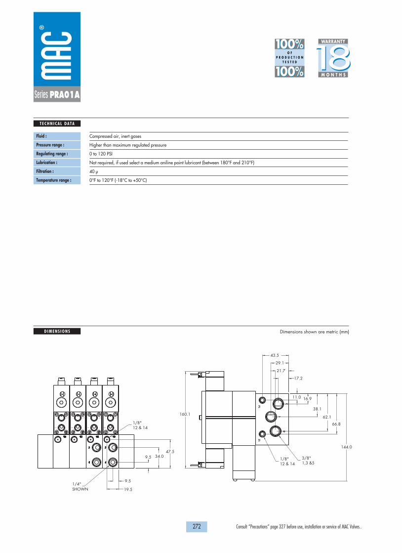
1818100%100%
100%100% M O N T H S
WARRANTY
O FP R O D U C T I O N
T E S T E D
D I M E N S I O N S
T E C H N I C A L D A T A
Dimensions shown are metric (mm)
272 Consult “Precautions” page 327 before use, installation or service of MAC Valves..
Series PRA01A
Fluid :
Pressure range :
Regulating range :
Lubrication :
Filtration :
Temperature range :
Compressed air, inert gases
Higher than maximum regulated pressure
0 to 120 PSI
Not required, if used select a medium aniline point lubricant (between 180°F and 210°F)
40 µ
0°F to 120°F (-18°C to +50°C)
144.0
PILOT
GAGE
PILOT
GAGE
PILOT
GAGE
PILOT
GAGE
1,3 &53/8"
12 & 141/8"
66.8
62.1
38.1
16.911.0
43.5
29.1
21.7
17.2
12 & 141/8"
SHOWN1/4"
47.534.09.5
19.5
9.5
160.1

H O W T O O R D E R
273 Consult “Precautions” page 327 before use, installation or service of MAC Valves..
P r e s s u r e r e g u l a t o r s
OPERATIONAL BENEFITS
Series
PR37APR42BPR46APR47APR48B
PRA02A
PR92C
PR93A
PRA1A
PRA01A
PRP1A
PRA2D
PRP2B
PRA3C
PRP3B
Series PRA02A
Non plug-in sandwich pressure regulator with manual adjust
1. Easy mounting: saves on installation costsand space in comparison with inlineregulators
2. Compact all-included units3. Large orifice provides high flow4. Various functions available5. Simple, reliable and solid design
Pilot
Internal
External
Single pressure Regulator 12 end
PRA02A-AAAA
PRA02A-BAAA
Dual pressure Regulator 12 end with
by-pass 14 end
PRA02A-ABAA
PRA02A-BBAA
Dual pressure Regulator 14 end with
by-pass 12 end
PRA02A-ADAA
PRA02A-BDAA
Dual pressureRegulator both ends
PRA02A-AEAA
PRA02A-BEAA
PRA02A – XXXX
OPTIONS
A Manual adjust with knob – Internal pilotB Manual adjust with knob – External pilotG Manual adjust with screwdriver slot – Internal pilotH Manual adjust with screwdriver slot – External pilotK Manual adjust with screwdriver slot with locknut– Internal pilotL Manual adjust with screwdriver slot with locknut – External pilot
Adjustments :
PRA02A – XXXX
A 0 to 120 PSIB 0 to 80 PSIC 0 to 30 PSID 0 to 120 PSI “14” end - 0 to 80 PSI “12” endE 0 to 120 PSI “12” end - 0 to 80 PSI “14” endF 0 to 120 PSI “14” end - 0 to 30 PSI “12” endG 0 to 120 PSI “12” end - 0 to 30 PSI “14” endH 0 to 80 PSI “14” end - 0 to 30 PSI “12” endJ 0 to 80 PSI “12” end - 0 to 30 PSI “14” end
Regulated Pressure range :
Above models are for manual adjust with knobFor other manual adjustments and pressure ranges, see Options.
Note: Add –9 after part number for regulator block assembled to valve.* To be used with dual pressure valves.
***

1818100%100%
100%100% M O N T H S
WARRANTY
O FP R O D U C T I O N
T E S T E D
D I M E N S I O N S
T E C H N I C A L D A T A
Dimensions shown are metric (mm)
274 Consult “Precautions” page 327 before use, installation or service of MAC Valves..
Series PRA02A
Fluid :
Pressure supply :
Regulating range :
Lubrication :
Filtration :
Temperature range :
Compressed air, inert gases
Higher than maximum regulated pressure
0 to 120 PSI
Not required, if used select a medium aniline point lubricant (between 180°F and 210°F)
40 µ
0°F to 120°F (-18°C to +50°C)
139.4
110.
5
144.0
ALL PORTS (7)1/8"
51.3
35.3
19.3
8.0

H O W T O O R D E R
275 Consult “Precautions” page 327 before use, installation or service of MAC Valves..
P r e s s u r e r e g u l a t o r s
OPERATIONAL BENEFITS
Series
PR37APR42BPR46APR47APR48B
PRA02A
PR92C
PR93A
PRA1A
PRA01A
PRP1A
PRA2D
PRP2B
PRA3C
PRP3B
Series PRA1A
Non plug-in sandwich pressure regulator with manual adjust knob
1. Easy mounting : saves on installation costs incomparison with inline regulators.
2. Allows to have compact, all-included units.3. Large orifice provides high flow.4. Various functions available.5. Simple, reliable and solid design.
Gage
No gage
Gage perpendicular to regulator(s)
Gage parallel
to regulator(s)
Single pressure Regulator 14 end
Same regulated pressureto ports 2 and 4
PRA1A-GAAA
PRA1A-GABA
PRA1A-GADA
Single pressure Regulator 12 end
Same regulated pressureto ports 2 and 4
PRA1A-GCAA
PRA1A-GCBA
PRA1A-GCDA
Dual pressure Regulator 14 end
Regulated pressure to port 4
PRA1A-GBAA
PRA1A-GBBA
PRA1A-GBDA
Dual pressure Regulator 12 end
Regulated pressure to port 2
PRA1A-GDAA
PRA1A-GDBA
PRA1A-GDDA
Dual pressure Dual regulator
Two regulated pressures to ports 2 and 4
PRA1A-GEAA
PRA1A-GECA
PRA1A-GEEA
INTERNAL PILOT
Gage
No gage
Gage perpendicular to regulator(s)
Gage parallel
to regulator(s)
Single pressure Regulator 14 end
Same regulated pressureto ports 2 and 4
PRA1A-HAAA
PRA1A-HABA
PRA1A-HADA
Single pressure Regulator 12 end
Same regulated pressureto ports 2 and 4
PRA1A-HCAA
PRA1A-HCBA
PRA1A-HCDA
Dual pressure Regulator 14 end
Regulated pressure to port 4
PRA1A-HBAA
PRA1A-HBBA
PRA1A-HBDA
Dual pressure Regulator 12 end
Regulated pressure to port 2
PRA1A-HDAA
PRA1A-HDBA
PRA1A-HDDA
Dual pressure Dual regulator
Two regulated pressures to ports 2 and 4
PRA1A-HEAA
PRA1A-HECA
PRA1A-HEEA
EXTERNAL PILOT AND REMOTE AIR
* - To be used with dual pressure valves. Note : regulating range for above models is 0-120 PSI. For other ranges see technical data page.
Main valve body assembly must be external pilot model. Pilotsare supplied internally from primary pressure in regulator block.Cannot field convert regulator block from Single Pressure to dualpressure. Body/Block to base mounting screw #35336.
* * *
* * *
PRA1A-XXXX
ADJUSTMENT OPTIONS
A for slotted stem adjustment (internal pilot)B for slotted stem adjustment (external/remote air)K for slotted stem with locknut (internal pilot)L for slotted stem with locknut (external/remote air)

1818100%100%
100%100% M O N T H S
WARRANTY
O FP R O D U C T I O N
T E S T E D
D I M E N S I O N S
T E C H N I C A L D A T A
Dimensions shown are metric (mm)
276 Consult “Precautions” page 327 before use, installation or service of MAC Valves..
Series PRA1A
Fluid :
Pressure range :
Regulating range :
Lubrication :
Filtration :
Temperature range :
Flow :
Compressed air, inert gases
0 to 150 PSI
0 to 120 PSI (other ranges see below)
Not required, if used select a medium aniline point lubricant (between 180°F to 210°F)
40 µ
0°F to 120°F (-18°C to +50°C)
1.0 Cv
214.7
297.3
214.7
• Pressure regulator (less sandwich block) : PRA1A-J0AA (KNOB), PRA1A-C0AA (SLOTTED STEM), PRA1A-M0AA (SLOTTED STEM WITH LOCKNUT).• Gage : N-82016-01 (0-120 PSI perpendicular)
N-82016-02 (0-120 PSI parallel)N-82016-03 (0-80 PSI perpendicular)N-82016-04 (0-80 PSI parallel)N-82016-05 (0-30 PSI perpendicular)N-82016-06 (0-30 PSI parallel)
PRA1A-XXXAReplace by B - 0 to 80 PSIReplace by C - 0 to 30 PSIReplace by D - 0 to 120 PSI on “14” end - 0 to 80 PSI on “12” endReplace by E - 0 to 120 PSI on “12” end - 0 to 80 PSI on “14” endReplace by F - 0 to 120 PSI on “14” end - 0 to 30 PSI on “12” endReplace by G - 0 to 120 PSI on “12” end - 0 to 30 PSI on “14” endReplace by H - 0 to 80 PSI on “14” end - 0 to 30 PSI on “12” endReplace by J - 0 to 80 PSI on “12” end - 0 to 30 PSI on “14” end
Spare parts :
Regulating range options :

H O W T O O R D E R
277 Consult “Precautions” page 327 before use, installation or service of MAC Valves..
P r e s s u r e r e g u l a t o r s
OPERATIONAL BENEFITS
Series
PR37APR42BPR46APR47APR48B
PRA02A
PR92C
PR93A
PRA1A
PRA01A
PRP1A
PRA2D
PRP2B
PRA3C
PRP3B
Series PRA1A
Non plug-in sandwich pressure regulator with air pilot adjust
1. Easy mounting : saves on installation costs incomparison with inline regulators.
2. Allows to have compact, all-included units.3. Large orifice provides high flow.4. Various functions available.5. Simple, reliable and solid design.
Gage
No gage
Gage perpendicular to regulator(s)
Gage parallel
to regulator(s)
Single pressure Regulator 14 end
Same regulated pressureto ports 2 and 4
PRA1A-DAAA
PRA1A-DABA
PRA1A-DADA
Single pressure Regulator 12 end
Same regulated pressureto ports 2 and 4
PRA1A-DCAA
PRA1A-DCBA
PRA1A-DCDA
Dual pressure Regulator 14 end
Regulated pressure to port 4
PRA1A-DBAA
PRA1A-DBBA
PRA1A-DBDA
Dual pressure Regulator 12 end
Regulated pressure to port 2
PRA1A-DDAA
PRA1A-DDBA
PRA1A-DDDA
Dual pressure Dual regulator
Two regulated pressures to ports 2 and 4
PRA1A-DEAA
PRA1A-DECA
PRA1A-DEEA
INTERNAL PILOT
Gage
No gage
Gage perpendicular to regulator(s)
Gage parallel
to regulator(s)
Single pressure Regulator 14 end
Same regulated pressureto ports 2 and 4
PRA1A-EAAA
PRA1A-EABA
PRA1A-EADA
Single pressure Regulator 12 end
Same regulated pressureto ports 2 and 4
PRA1A-ECAA
PRA1A-ECBA
PRA1A-ECDA
Dual pressure Regulator 14 end
Regulated pressure to port 4
PRA1A-EBAA
PRA1A-EBBA
PRA1A-EBDA
Dual pressure Regulator 12 end
Regulated pressure to port 2
PRA1A-EDAA
PRA1A-EDBA
PRA1A-EDDA
Dual pressure Dual regulator
Two regulated pressures to ports 2 and 4
PRA1A-EEAA
PRA1A-EECA
PRA1A-EEEA
EXTERNAL PILOT AND REMOTE AIR
* - To be used with dual pressure valves.
* * *
* * *
Main valve body assembly must be external pilot model. Pilotsare supplied internally from primary pressure in regulator block.Cannot field convert regulator block from Single Pressure to dualpressure. Body/Block to base mounting screw #35336.

243.6
194.1
194.1
1818100%100%
100%100% M O N T H S
WARRANTY
O FP R O D U C T I O N
T E S T E D
D I M E N S I O N S
T E C H N I C A L D A T A
Dimensions shown are metric (mm)
278 Consult “Precautions” page 327 before use, installation or service of MAC Valves..Consult “Precautions” page 327 before use, installation or service of MAC Valves..
Series PRA1A
Fluid :
Pressure range :
Regulating range :
Lubrication :
Filtration :
Temperature range :
Flow :
Compressed air, inert gases
0 to 150 PSI
0 to 120 PSI
Not required, if used select a medium aniline point lubricant (between 180°F to 210°F)
40 µ
0°F to 120°F (-18°C to +50°C)
1.0 Cv
• Pressure regulator (less sandwich block) : PRA1A-F0AA.• Gage : N-82016-01 (0-120 PSI perpendicular)
N-82016-02 (0-120 PSI parallel)
Spare parts :

H O W T O O R D E R
279 Consult “Precautions” page 327 before use, installation or service of MAC Valves..
P r e s s u r e r e g u l a t o r s
OPERATIONAL BENEFITS
Series
PR37APR42BPR46APR47APR48B
PRA02A
PR92C
PR93A
PRA1A
PRA01A
PRP1A
PRA2D
PRP2B
PRA3C
PRP3B
Series PRP1A
Plug-in sandwich pressure regulator with manual adjust knob
1. Easy mounting: saves on installation costs incomparison with inline regulators.
2. Compact all-included units.3. Large orifice provides high flow.4. Various functions available.5. Simple, reliable and solid design.
* For use with dual pressure valves.Note: Regulating range for above models is 0 -120 PSI. For other ranges see technical data page.
Notes:1. Valves used with above models must be external pilot models.2. Cannot field convert regulator block from single pressure to dual pressure.3. Cannot field convert from internal pilot to external pilot.4. Wired for double solenoid valves.
PRP1A-XXXX
ADJUSTMENT OPTIONS
A for slotted stem adjustment (internal pilot)B for slotted stem adjustment (external/remote air)K for slotted stem with locknut (internal pilot)L for slotted stem with locknut (external/remote air)
Gage
Gage port only
Gage perpendicular to manual operator
Gage parallel to manual operator
Single pressure Regulator 14 end
Same regulated pressureto ports 2 and 4
PRP1A-GAKA
PRP1A-GABA
PRP1A-GADA
Single pressure Regulator 12 end
Same regulated pressureto ports 2 and 4
PRP1A-GCKA
PRP1A-GCBA
PRP1A-GCDA
Dual pressure Regulator 14 end
Regulated pressure to port 4
PRP1A-GBKA
PRP1A-GBBA
PRP1A-GBDA
Dual pressure Regulator 12 end
Regulated pressure to port 2
PRP1A-GDKA
PRP1A-GDBA
PRP1A-GDDA
Dual pressure Dual regulator
Two regulated pressures to ports 2 and 4
PRP1A-GEKA
PRP1A-GECA
PRP1A-GEEA
REGULATORS FOR INTERNAL PILOT (CODED FOR KNOB ADJUSTMENT)
Gage
No gage
Gage perpendicular to manual operator
Gage parallel to manual operator
Single pressure Regulator 14 end
Same regulated pressureto ports 2 and 4
PRP1A-HAKA
PRP1A-HABA
PRP1A-HADA
Single pressure Regulator 12 end
Same regulated pressureto ports 2 and 4
PRP1A-HCKA
PRP1A-HCBA
PRP1A-HCDA
Dual pressure Regulator 14 end
Regulated pressure to port 4
PRP1A-HBKA
PRP1A-HBBA
PRP1A-HBDA
Dual pressure Regulator 12 end
Regulated pressure to port 2
PRP1A-HDKA
PRP1A-HDBA
PRP1A-HDDA
Dual pressure Dual regulator
Two regulated pressures to ports 2 and 4
PRP1A-HEKA
PRP1A-HECA
PRP1A-HEEA
REGULATORS FOR EXTERNAL PILOT AND REMOTE AIR (CODED FOR KNOB ADJUSTMENT)
* * *
* * *

214.7
297.3
214.7
1
5
3
COND
180.4
1818100%100%
100%100% M O N T H S
WARRANTY
O FP R O D U C T I O N
T E S T E D
D I M E N S I O N S
T E C H N I C A L D A T A
Dimensions shown are metric (mm)
280 Consult “Precautions” page 327 before use, installation or service of MAC Valves..
Series PRP1A
Fluid :
Pressure range :
Regulating range :
Lubrication :
Filtration :
Temperature range :
Flow :
Compressed air, inert gases
0 to 150 PSI
0 to 120 PSI (other ranges see below)
Not required, if used select a medium aniline point lubricant (between 180°F to 210°F)
40 µ
0°F to 120°F (-18°C to +50°C)
1.1 Cv
• Pressure regulator (less sandwich block) : PRP1A-J0KA (knob), PRP1A-C0KA (slotted stem)PRP1A-M0KA (slotted stem with locknut)
PRP1A-XXXAReplace by B - 0 to 80 PSIReplace by C - 0 to 30 PSIReplace by D - 0 to 120 PSI on “14” end - 0 to 80 PSI on “12” endReplace by E - 0 to 120 PSI on “12” end - 0 to 80 PSI on “14” endReplace by F - 0 to 120 PSI on “14” end - 0 to 30 PSI on “12” endReplace by G - 0 to 120 PSI on “12” end - 0 to 30 PSI on “14” endReplace by H - 0 to 80 PSI on “14” end - 0 to 30 PSI on “12” endReplace by J - 0 to 80 PSI on “12” end - 0 to 30 PSI on “14” end
Spare parts :
Regulating range options :

H O W T O O R D E R
281 Consult “Precautions” page 327 before use, installation or service of MAC Valves..
P r e s s u r e r e g u l a t o r s
OPERATIONAL BENEFITS
Series
PR37APR42BPR46APR47APR48B
PRA02A
PR92C
PR93A
PRA1A
PRA01A
PRP1A
PRA2D
PRP2B
PRA3C
PRP3B
Series PRP1A
Plug-in sandwich pressure regulator with air pilot adjust
1. Easy mounting: saves on installation costs incomparison with inline regulators.
2. Compact all-included units.3. Large orifice provides high flow.4. Various functions available.5. Simple, reliable and solid design.
* - To be used with dual pressure valves. Notes:1. Valves used with above models must be external pilot models.2. Cannot field convert regulator block from single pressure to dual pressure.3. Cannot field convert from internal pilot to external pilot.4. Wired for double solenoid valves.
Gage
Gage port only
Gage perpendicular to manual operator
Gage parallel to manual operator
Single pressure Regulator 14 end
Same regulated pressureto ports 2 and 4
PRP1A-DAKA
PRP1A-DABA
PRP1A-DADA
Single pressure Regulator 12 end
Same regulated pressureto ports 2 and 4
PRP1A-DCKA
PRP1A-DCBA
PRP1A-DCDA
Dual pressure Regulator 14 end
Regulated pressure to port 4
PRP1A-DBKA
PRP1A-DBBA
PRP1A-DBDA
Dual pressure Regulator 12 end
Regulated pressure to port 2
PRP1A-DDKA
PRP1A-DDBA
PRP1A-DDDA
Dual pressure Dual regulator
Two regulated pressures to ports 2 and 4
PRP1A-DEKA
PRP1A-DECA
PRP1A-DEEA
REGULATORS FOR INTERNAL PILOT
Gage
Gage port only
Gage perpendicular to manual operator
Gage parallel to manual operator
Single pressure Regulator 14 end
Same regulated pressureto ports 2 and 4
PRP1A-EAKA
PRP1A-EABA
PRP1A-EADA
Single pressure Regulator 12 end
Same regulated pressureto ports 2 and 4
PRP1A-ECKA
PRP1A-ECBA
PRP1A-ECDA
Dual pressure Regulator 14 end
Regulated pressure to port 4
PRP1A-EBKA
PRP1A-EBBA
PRP1A-EBDA
Dual pressure Regulator 12 end
Regulated pressure to port 2
PRP1A-EDKA
PRP1A-EDBA
PRP1A-EDDA
Dual pressure Dual regulator
Two regulated pressures to ports 2 and 4
PRP1A-EEKA
PRP1A-EECA
PRP1A-EEEA
REGULATORS FOR EXTERNAL PILOT AND REMOTE AIR
* * *
* * *

218.1SINGLE AND DOUBLE SOLENOIDSSINGLE REGULATOR 12 END
SINGLE REGULATOR 14 ENDSINGLE AND DOUBLE SOLENOIDS
1
5
3
COND
APPROX. WITH DOUBLE REGULATORSINGLE AND DOUBLE SOLENOIDS
269.3
211.3
1818100%100%
100%100% M O N T H S
WARRANTY
O FP R O D U C T I O N
T E S T E D
D I M E N S I O N S
T E C H N I C A L D A T A
Dimensions shown are metric (mm)
282 Consult “Precautions” page 327 before use, installation or service of MAC Valves..
Series PRP1A
Fluid :
Pressure range :
Regulating range :
Lubrication :
Filtration :
Temperature range :
Flow :
Compressed air, inert gases
0 to 150 PSI
0 to 120 PSI
Not required, if used select a medium aniline point lubricant (between 180°F to 210°F)
40 µ
0°F to 120°F (-18°C to +50°C)
1.1 Cv
• Pressure regulator (less sandwich block): PRP1A-F0KA• Regulator block to base mounting tie rod: 19496
Spare parts :

H O W T O O R D E R
283 Consult “Precautions” page 327 before use, installation or service of MAC Valves..
P r e s s u r e r e g u l a t o r s
OPERATIONAL BENEFITS
Series
PR37APR42BPR46APR47APR48B
PRA02A
PR92C
PR93A
PRA1A
PRA01A
PRP1A
PRA2D
PRP2B
PRA3C
PRP3B
Series PRA2D
Non plug-in sandwich pressure regulator with manual adjust knob
1. Easy mounting : saves on installation costs incomparison with inline regulators.
2. Allows to have compact, all-included units.3. Large orifice provides high flow.4. Various functions available.5. Simple, reliable and solid design.
Gage
No gage
Non-filled gage on regulator(s)
Non-filled gage opposite to regulator
Glycerine filled gage on regulator(s)
Glycerine filled gage opposite to regulator
Single pressure Regulator 14 end
Same regulated pressureto ports 2 and 4
PRA2D-1AAA
PRA2D-1ADA
PRA2D-1CDA
PRA2D-1ABA
PRA2D-1CBA
Single pressure Regulator 12 end
Same regulated pressureto ports 2 and 4
PRA2D-1EAA
PRA2D-1EDA
PRA2D-1GDA
PRA2D-1EBA
PRA2D-1GBA
Dual pressure Regulator 14 end
Regulated pressure to port 4
PRA2D-1BAA
PRA2D-1BDA
PRA2D-1DDA
PRA2D-1BBA
PRA2D-1DBA
Dual pressure Regulator 12 end
Regulated pressure to port 2
PRA2D-1FAA
PRA2D-1FDA
PRA2D-1HDA
PRA2D-1FBA
PRA2D-1HBA
Dual pressure Dual regulator
Two regulated pressures to ports 2 and 4
PRA2D-1JAA
PRA2D-1JEA
-----
PRA2D-1JCA
-----
INTERNAL PILOT* * *
Gage
No gage
Non-filled gage on regulator(s)
Non-filled gage opposite to regulator
Glycerine filled gage on regulator(s)
Glycerine filled gage opposite to regulator
Single pressure Regulator 14 end
Same regulated pressureto ports 2 and 4
PRA2D-2AAA
PRA2D-2ADA
PRA2D-2CDA
PRA2D-2ABA
PRA2D-2CBA
Single pressure Regulator 12 end
Same regulated pressureto ports 2 and 4
PRA2D-2EAA
PRA2D-2EDA
PRA2D-2GDA
PRA2D-2EBA
PRA2D-2GBA
Dual pressure Regulator 14 end
Regulated pressure to port 4
PRA2D-2BAA
PRA2D-2BDA
PRA2D-2DDA
PRA2D-2BBA
PRA2D-2DBA
Dual pressure Regulator 12 end
Regulated pressure to port 2
PRA2D-2FAA
PRA2D-2FDA
PRA2D-2HDA
PRA2D-2FBA
PRA2D-2HBA
Dual pressure Dual regulator
Two regulated pressures to ports 2 and 4
PRA2D-2JAA
PRA2D-2JEA
-----
PRA2D-2JCA
-----
EXTERNAL PILOT AND REMOTE AIR* * *
* - To be used with dual pressure valves. Note : regulating range for above models is 0-150 PSI. For other ranges see technical data page.
PRA2D-XXXX
ADJUSTMENT OPTIONS
A for slotted stem adjustment (internal pilot)B for slotted stem adjustment (external pilot)D for slotted stem with locknut (internal pilot)E for slotted stem with locknut (external pilot)
Main valve body assembly must be external pilot model. Pilotsare supplied internally from primary pressure in regulator block.Cannot field convert regulator block from Single Pressure to dualpressure. Body/Block to base mounting screw #19177.
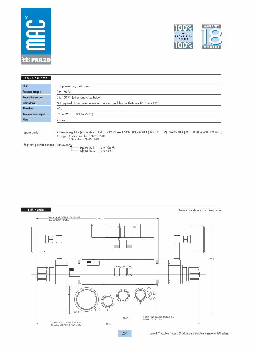
252.4
1
5
3
COND
186.1
273.5
337.9REGULATORS "14" & "12" ENDSSINGLE AND DOUBLE SOLENOIDS
REGULATOR "12" ENDSINGLE AND DOUBLE SOLENOIDS
REGULATOR "14" ENDSINGLE AND DOUBLE SOLENOIDS
1818100%100%
100%100% M O N T H S
WARRANTY
O FP R O D U C T I O N
T E S T E D
D I M E N S I O N S
T E C H N I C A L D A T A
Dimensions shown are metric (mm)
284 Consult “Precautions” page 327 before use, installation or service of MAC Valves..
Series PRA2D
Fluid :
Pressure range :
Regulating range :
Lubrication :
Filtration :
Temperature range :
Flow :
Compressed air, inert gases
0 to 150 PSI
0 to 150 PSI (other ranges see below)
Not required, if used select a medium aniline point lubricant (between 180°F to 210°F)
40 µ
0°F to 120°F (-18°C to +50°C)
2.3 Cv
• Pressure regulator (less sandwich block) : PRA2D-30AA (KNOB), PRA2D-C0AA (SLOTTED STEM), PRA2D-F0AA (SLOTTED STEM WITH LOCKNUT).• Gage : • Glycerine filled : N-62015-01
• Non filled : N-62016-01
PRA2D-XXXAReplace by B - 0 to 100 PSIReplace by C - 0 to 45 PSI
Spare parts :
Regulating range options :

H O W T O O R D E R
285 Consult “Precautions” page 327 before use, installation or service of MAC Valves..
P r e s s u r e r e g u l a t o r s
OPERATIONAL BENEFITS
Series
PR37APR42BPR46APR47APR48B
PRA02A
PR92C
PR93A
PRA1A
PRA01A
PRP1A
PRA2D
PRP2B
PRA3C
PRP3B
Series PRA2D
Non plug-in sandwich pressure regulator with air pilot adjust
1. Easy mounting : saves on installation costs incomparison with inline regulators.
2. Allows to have compact, all-included units.3. Large orifice provides high flow.4. Various functions available.5. Simple, reliable and solid design.
Gage
No gage
Non-filled gage on regulator(s)
Non-filled gage opposite to regulator
Glycerine filled gage on regulator(s)
Glycerine filled gage opposite to regulator
Single pressure Regulator 14 end
Same regulated pressureto ports 2 and 4
PRA2D-4AAA
PRA2D-4ADA
PRA2D-4CDA
PRA2D-4ABA
PRA2D-4CBA
Single pressure Regulator 12 end
Same regulated pressureto ports 2 and 4
PRA2D-4EAA
PRA2D-4EDA
PRA2D-4GDA
PRA2D-4EBA
PRA2D-4GBA
Dual pressure Regulator 14 end
Regulated pressure to port 4
PRA2D-4BAA
PRA2D-4BDA
PRA2D-4DDA
PRA2D-4BBA
PRA2D-4DBA
Dual pressure Regulator 12 end
Regulated pressure to port 2
PRA2D-4FAA
PRA2D-4FDA
PRA2D-4HDA
PRA2D-4FBA
PRA2D-4HBA
Dual pressure Dual regulator
Two regulated pressures to ports 2 and 4
PRA2D-4JAA
PRA2D-4JEA
-----
PRA2D-4JCA
-----
INTERNAL PILOT* * *
Gage
No gage
Non-filled gage on regulator(s)
Non-filled gage opposite to regulator
Glycerine filled gage on regulator(s)
Glycerine filled gage opposite to regulator
Single pressure Regulator 14 end
Same regulated pressureto ports 2 and 4
PRA2D-5AAA
PRA2D-5ADA
PRA2D-5CDA
PRA2D-5ABA
PRA2D-5CBA
Single pressure Regulator 12 end
Same regulated pressureto ports 2 and 4
PRA2D-5EAA
PRA2D-5EDA
PRA2D-5GDA
PRA2D-5EBA
PRA2D-5GBA
Dual pressure Regulator 14 end
Regulated pressure to port 4
PRA2D-5BAA
PRA2D-5BDA
PRA2D-5DDA
PRA2D-5BBA
PRA2D-5DBA
Dual pressure Regulator 12 end
Regulated pressure to port 2
PRA2D-5FAA
PRA2D-5FDA
PRA2D-5HDA
PRA2D-5FBA
PRA2D-5HBA
Dual pressure Dual regulator
Two regulated pressures to ports 2 and 4
PRA2D-5JAA
PRA2D-5JEA
-----
PRA2D-5JCA
-----
EXTERNAL PILOT AND REMOTE AIR* * *
* - To be used with dual pressure valves.
Main valve body assembly must be external pilot model. Pilotsare supplied internally from primary pressure in regulator block.Cannot field convert regulator block from Single Pressure to dualpressure. Body/Block to base mounting screw #19177.

SINGLE AND DOUBLE SOLENOIDS REGULATOR "12" END
SINGLE AND DOUBLE SOLENOIDREGULATOR "14" END
APPROX.
APPROX.211.1
187.1
205.8
1818100%100%
100%100% M O N T H S
WARRANTY
O FP R O D U C T I O N
T E S T E D
D I M E N S I O N S
T E C H N I C A L D A T A
Dimensions shown are metric (mm)
286 Consult “Precautions” page 327 before use, installation or service of MAC Valves..
Series PRA2D
Fluid :
Pressure range :
Regulating range :
Lubrication :
Filtration :
Temperature range :
Flow :
Compressed air, inert gases
0 to 150 PSI
0 to 150 PSI
Not required, if used select a medium aniline point lubricant (between 180°F to 210°F)
40 µ
0°F to 120°F (-18°C to +50°C)
2.3 Cv
• Pressure regulator (less sandwich block) : PRA2D-60AA.• Gage : • Glycerine filled : N-62015-01
• Non filled : N-62016-01
Spare parts :
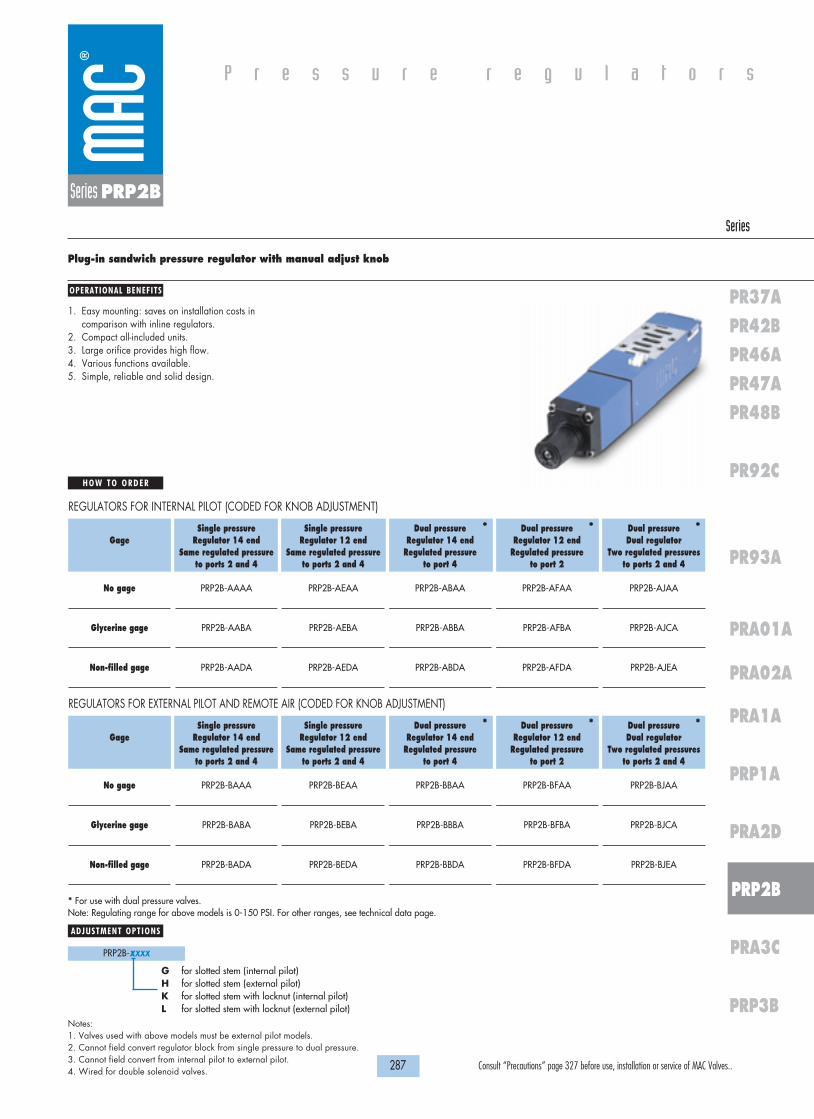
H O W T O O R D E R
287 Consult “Precautions” page 327 before use, installation or service of MAC Valves..
P r e s s u r e r e g u l a t o r s
OPERATIONAL BENEFITS
Series
PR37APR42BPR46APR47APR48B
PRA02A
PR92C
PR93A
PRA1A
PRA01A
PRP1A
PRA2D
PRP2B
PRA3C
PRP3B
Series PRP2B
Plug-in sandwich pressure regulator with manual adjust knob
1. Easy mounting: saves on installation costs incomparison with inline regulators.
2. Compact all-included units.3. Large orifice provides high flow.4. Various functions available.5. Simple, reliable and solid design.
* For use with dual pressure valves.Note: Regulating range for above models is 0-150 PSI. For other ranges, see technical data page.
Notes:1. Valves used with above models must be external pilot models.2. Cannot field convert regulator block from single pressure to dual pressure.3. Cannot field convert from internal pilot to external pilot.4. Wired for double solenoid valves.
PRP2B-XXXX
ADJUSTMENT OPTIONS
G for slotted stem (internal pilot)H for slotted stem (external pilot)K for slotted stem with locknut (internal pilot)L for slotted stem with locknut (external pilot)
Gage
No gage
Glycerine gage
Non-filled gage
Single pressure Regulator 14 end
Same regulated pressureto ports 2 and 4
PRP2B-AAAA
PRP2B-AABA
PRP2B-AADA
Single pressure Regulator 12 end
Same regulated pressureto ports 2 and 4
PRP2B-AEAA
PRP2B-AEBA
PRP2B-AEDA
Dual pressure Regulator 14 end
Regulated pressure to port 4
PRP2B-ABAA
PRP2B-ABBA
PRP2B-ABDA
Dual pressure Regulator 12 end
Regulated pressure to port 2
PRP2B-AFAA
PRP2B-AFBA
PRP2B-AFDA
Dual pressure Dual regulator
Two regulated pressures to ports 2 and 4
PRP2B-AJAA
PRP2B-AJCA
PRP2B-AJEA
REGULATORS FOR INTERNAL PILOT (CODED FOR KNOB ADJUSTMENT)
Gage
No gage
Glycerine gage
Non-filled gage
Single pressure Regulator 14 end
Same regulated pressureto ports 2 and 4
PRP2B-BAAA
PRP2B-BABA
PRP2B-BADA
Single pressure Regulator 12 end
Same regulated pressureto ports 2 and 4
PRP2B-BEAA
PRP2B-BEBA
PRP2B-BEDA
Dual pressure Regulator 14 end
Regulated pressure to port 4
PRP2B-BBAA
PRP2B-BBBA
PRP2B-BBDA
Dual pressure Regulator 12 end
Regulated pressure to port 2
PRP2B-BFAA
PRP2B-BFBA
PRP2B-BFDA
Dual pressure Dual regulator
Two regulated pressures to ports 2 and 4
PRP2B-BJAA
PRP2B-BJCA
PRP2B-BJEA
REGULATORS FOR EXTERNAL PILOT AND REMOTE AIR (CODED FOR KNOB ADJUSTMENT)
* * *
* * *

276.9
186.1
299.3
388.9
11
55
33
COND
1818100%100%
100%100% M O N T H S
WARRANTY
O FP R O D U C T I O N
T E S T E D
D I M E N S I O N S
T E C H N I C A L D A T A
Dimensions shown are metric (mm)
288 Consult “Precautions” page 327 before use, installation or service of MAC Valves..
Series PRP2B
Fluid :
Pressure range :
Regulating range :
Lubrication :
Filtration :
Temperature range :
Flow :
Compressed air, inert gases
0 to 150 PSI
0 to 150 PSI (other ranges see below)
Not required, if used select a medium aniline point lubricant (between 180°F to 210°F)
40 µ
0°F to 120°F (-18°C to +50°C)
3.1 Cv
• Pressure regulator (less sandwich block) : PRP2B-C0AA (knob), PRP2B-J0AA (slotted stem), PRP2B-M0AA (slotted stem with locknut)• Regulator block to base mounting screw: 19177• Regulating range option: PRP2B-xxxA
Replace by B for 0 to 100 PSIReplace by C for 0 to 45 PSI
Spare parts :

H O W T O O R D E R
289 Consult “Precautions” page 327 before use, installation or service of MAC Valves..
P r e s s u r e r e g u l a t o r s
OPERATIONAL BENEFITS
Series
PR37APR42BPR46APR47APR48B
PRA02A
PR92C
PR93A
PRA1A
PRA01A
PRP1A
PRA2D
PRP2B
PRA3C
PRP3B
Series PRP2B
Plug-in sandwich pressure regulator with air pilot adjust
1. Easy mounting: saves on installation costs incomparison with inline regulators.
2. Compact all-included units.3. Large orifice provides high flow.4. Various functions available.5. Simple, reliable and solid design.
* - To be used with dual pressure valves. Notes:1. Valves used with above models must be external pilot models.2. Cannot field convert regulator block from single pressure to dual pressure.3. Cannot field convert from internal pilot to external pilot.4. Wired for double solenoid valves.
Gage
No gage
Glycerine gage
Non-filled gage
Single pressure Regulator 14 end
Same regulated pressureto ports 2 and 4
PRP2B-DAAA
PRP2B-DABA
PRP2B-DADA
Single pressure Regulator 12 end
Same regulated pressureto ports 2 and 4
PRP2B-DEAA
PRP2B-DEBA
PRP2B-DEDA
Dual pressure Regulator 14 end
Regulated pressure to port 4
PRP2B-DBAA
PRP2B-DBBA
PRP2B-DBDA
Dual pressure Regulator 12 end
Regulated pressure to port 2
PRP2B-DFAA
PRP2B-DFBA
PRP2B-DFDA
Dual pressure Dual regulator
Two regulated pressures to ports 2 and 4
PRP2B-DJAA
PRP2B-DJCA
PRP2B-DJEA
REGULATORS FOR INTERNAL PILOT
Gage
No gage
Glycerine gage
Non-filled gage
Single pressure Regulator 14 end
Same regulated pressureto ports 2 and 4
PRP2B-EAAA
PRP2B-EABA
PRP2B-EADA
Single pressure Regulator 12 end
Same regulated pressureto ports 2 and 4
PRP2B-EEAA
PRP2B-EEBA
PRP2B-EEDA
Dual pressure Regulator 14 end
Regulated pressure to port 4
PRP2B-EBAA
PRP2B-EBBA
PRP2B-EBDA
Dual pressure Regulator 12 end
Regulated pressure to port 2
PRP2B-EFAA
PRP2B-EFBA
PRP2B-EFDA
Dual pressure Dual regulator
Two regulated pressures to ports 2 and 4
PRP2B-EJAA
PRP2B-EJCA
PRP2B-EJEA
REGULATORS FOR EXTERNAL PILOT AND REMOTE AIR
* * *
* * *

305.9
235.9
186.1
1
5
3
COND
1818100%100%
100%100% M O N T H S
WARRANTY
O FP R O D U C T I O N
T E S T E D
D I M E N S I O N S
T E C H N I C A L D A T A
Dimensions shown are metric (mm)
290 Consult “Precautions” page 327 before use, installation or service of MAC Valves..
Series PRP2B
Fluid :
Pressure range :
Regulating range :
Lubrication :
Filtration :
Temperature range :
Flow :
Compressed air, inert gases
0 to 150 PSI
0 to 150 PSI
Not required, if used select a medium aniline point lubricant (between 180°F to 210°F)
40 µ
0°F to 120°F (-18°C to +50°C)
3.1 Cv
• Pressure regulator (less sandwich block): PRP2B-F0AA• Body/block to base mounting screw: 19177
Spare parts :
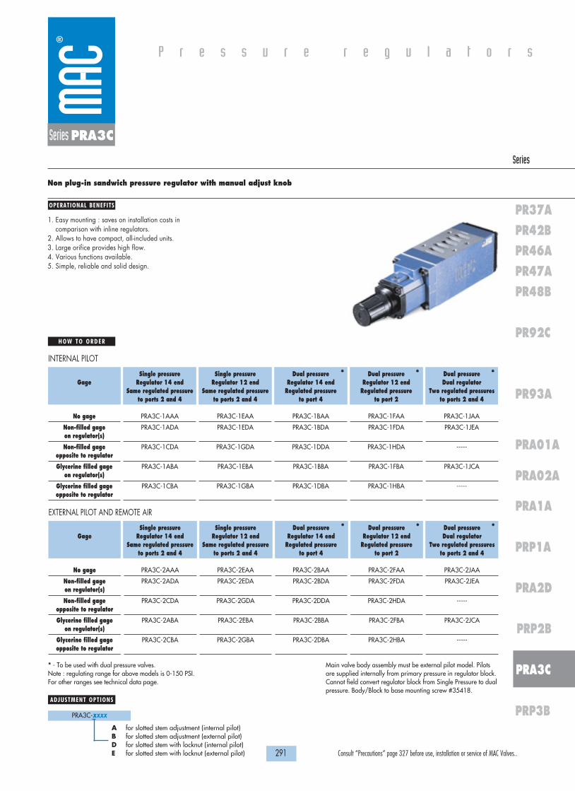
H O W T O O R D E R
291 Consult “Precautions” page 327 before use, installation or service of MAC Valves..
P r e s s u r e r e g u l a t o r s
OPERATIONAL BENEFITS
Series
PR37APR42BPR46APR47APR48B
PRA02A
PR92C
PR93A
PRA1A
PRA01A
PRP1A
PRA2D
PRP2B
PRA3C
PRP3B
Series PRA3C
Non plug-in sandwich pressure regulator with manual adjust knob
1. Easy mounting : saves on installation costs incomparison with inline regulators.
2. Allows to have compact, all-included units.3. Large orifice provides high flow.4. Various functions available.5. Simple, reliable and solid design.
Gage
No gage
Non-filled gage on regulator(s)
Non-filled gage opposite to regulator
Glycerine filled gage on regulator(s)
Glycerine filled gage opposite to regulator
Single pressure Regulator 14 end
Same regulated pressureto ports 2 and 4
PRA3C-1AAA
PRA3C-1ADA
PRA3C-1CDA
PRA3C-1ABA
PRA3C-1CBA
Single pressure Regulator 12 end
Same regulated pressureto ports 2 and 4
PRA3C-1EAA
PRA3C-1EDA
PRA3C-1GDA
PRA3C-1EBA
PRA3C-1GBA
Dual pressure Regulator 14 end
Regulated pressure to port 4
PRA3C-1BAA
PRA3C-1BDA
PRA3C-1DDA
PRA3C-1BBA
PRA3C-1DBA
Dual pressure Regulator 12 end
Regulated pressure to port 2
PRA3C-1FAA
PRA3C-1FDA
PRA3C-1HDA
PRA3C-1FBA
PRA3C-1HBA
Dual pressure Dual regulator
Two regulated pressures to ports 2 and 4
PRA3C-1JAA
PRA3C-1JEA
-----
PRA3C-1JCA
-----
INTERNAL PILOT* * *
Gage
No gage
Non-filled gage on regulator(s)
Non-filled gage opposite to regulator
Glycerine filled gage on regulator(s)
Glycerine filled gage opposite to regulator
Single pressure Regulator 14 end
Same regulated pressureto ports 2 and 4
PRA3C-2AAA
PRA3C-2ADA
PRA3C-2CDA
PRA3C-2ABA
PRA3C-2CBA
Single pressure Regulator 12 end
Same regulated pressureto ports 2 and 4
PRA3C-2EAA
PRA3C-2EDA
PRA3C-2GDA
PRA3C-2EBA
PRA3C-2GBA
Dual pressure Regulator 14 end
Regulated pressure to port 4
PRA3C-2BAA
PRA3C-2BDA
PRA3C-2DDA
PRA3C-2BBA
PRA3C-2DBA
Dual pressure Regulator 12 end
Regulated pressure to port 2
PRA3C-2FAA
PRA3C-2FDA
PRA3C-2HDA
PRA3C-2FBA
PRA3C-2HBA
Dual pressure Dual regulator
Two regulated pressures to ports 2 and 4
PRA3C-2JAA
PRA3C-2JEA
-----
PRA3C-2JCA
-----
EXTERNAL PILOT AND REMOTE AIR* * *
* - To be used with dual pressure valves. Note : regulating range for above models is 0-150 PSI. For other ranges see technical data page.
PRA3C-XXXX
ADJUSTMENT OPTIONS
A for slotted stem adjustment (internal pilot)B for slotted stem adjustment (external pilot)D for slotted stem with locknut (internal pilot)E for slotted stem with locknut (external pilot)
Main valve body assembly must be external pilot model. Pilotsare supplied internally from primary pressure in regulator block.Cannot field convert regulator block from Single Pressure to dualpressure. Body/Block to base mounting screw #35418.

1818100%100%
100%100% M O N T H S
WARRANTY
O FP R O D U C T I O N
T E S T E D
D I M E N S I O N S
T E C H N I C A L D A T A
Dimensions shown are metric (mm)
292 Consult “Precautions” page 327 before use, installation or service of MAC Valves..
Series PRA3C
Fluid :
Pressure range :
Regulating range :
Lubrication :
Filtration :
Temperature range :
Flow :
Compressed air, inert gases
0 to 150 PSI
0 to 150 PSI (other ranges see below)
Not required, if used select a medium aniline point lubricant (between 180°F to 210°F)
40 µ
0°F to 120°F (-18°C to +50°C)
5.4 Cv
AUCK
LAN
D,N
.Z.
LIEG
E,BE
LGIU
MW
IXO
M,M
I. US
AM
OD
IF.
MO
DEL
ELEC
TRIC
AL
WA
TTS
VAC
TO
120
PSI
432.3
DOUBLE REGULATORAPPROX. WITH
7
3
5
1
COND
324.3
340.1
REGULATOR '14' ENDAPPROX. WITH
REGOLATOR '12' ENDAPPROX. WITH
78.0
234.0
• Pressure regulator (less sandwich block) : PRA3C-30AA (KNOB), PRA3C-C0AA (SLOTTED STEM), PRA3C-F0AA (SLOTTED STEM WITH LOCKNUT).• Gage : • Glycerine filled : N-62015-01
• Non filled : N-62016-01
PRA3C-XXXAReplace by B - 0 to 100 PSIReplace by C - 0 to 45 PSI
Spare parts :
Regulating range options :

H O W T O O R D E R
293 Consult “Precautions” page 327 before use, installation or service of MAC Valves..
P r e s s u r e r e g u l a t o r s
OPERATIONAL BENEFITS
Series
PR37APR42BPR46APR47APR48B
PRA02A
PR92C
PR93A
PRA1A
PRA01A
PRP1A
PRA2D
PRP2B
PRA3C
PRP3B
Series PRA3C
Non plug-in sandwich pressure regulator with air pilot adjust
1. Easy mounting : saves on installation costs incomparison with inline regulators.
2. Allows to have compact, all-included units.3. Large orifice provides high flow.4. Various functions available.5. Simple, reliable and solid design.
Gage
No gage
Non-filled gage on regulator(s)
Non-filled gage opposite to regulator
Glycerine filled gage on regulator(s)
Glycerine filled gage opposite to regulator
Single pressure Regulator 14 end
Same regulated pressureto ports 2 and 4
PRA3C-4AAA
PRA3C-4ADA
PRA3C-4CDA
PRA3C-4ABA
PRA3C-4CBA
Single pressure Regulator 12 end
Same regulated pressureto ports 2 and 4
PRA3C-4EAA
PRA3C-4EDA
PRA3C-4GDA
PRA3C-4EBA
PRA3C-4GBA
Dual pressure Regulator 14 end
Regulated pressure to port 4
PRA3C-4BAA
PRA3C-4BDA
PRA3C-4DDA
PRA3C-4BBA
PRA3C-4DBA
Dual pressure Regulator 12 end
Regulated pressure to port 2
PRA3C-4FAA
PRA3C-4FDA
PRA3C-4HDA
PRA3C-4FBA
PRA3C-4HBA
Dual pressure Dual regulator
Two regulated pressures to ports 2 and 4
PRA3C-4JAA
PRA3C-4JEA
-----
PRA3C-4JCA
-----
INTERNAL PILOT* * *
Gage
No gage
Non-filled gage on regulator(s)
Non-filled gage opposite to regulator
Glycerine filled gage on regulator(s)
Glycerine filled gage opposite to regulator
Single pressure Regulator 14 end
Same regulated pressureto ports 2 and 4
PRA3C-5AAA
PRA3C-5ADA
PRA3C-5CDA
PRA3C-5ABA
PRA3C-5CBA
Single pressure Regulator 12 end
Same regulated pressureto ports 2 and 4
PRA3C-5EAA
PRA3C-5EDA
PRA3C-5GDA
PRA3C-5EBA
PRA3C-5GBA
Dual pressure Regulator 14 end
Regulated pressure to port 4
PRA3C-5BAA
PRA3C-5BDA
PRA3C-5DDA
PRA3C-5BBA
PRA3C-5DBA
Dual pressure Regulator 12 end
Regulated pressure to port 2
PRA3C-5FAA
PRA3C-5FDA
PRA3C-5HDA
PRA3C-5FBA
PRA3C-5HBA
Dual pressure Dual regulator
Two regulated pressures to ports 2 and 4
PRA3C-5JAA
PRA3C-5JEA
-----
PRA3C-5JCA
-----
EXTERNAL PILOT AND REMOTE AIR* * *
* - To be used with dual pressure valves.
Main valve body assembly must be external pilot model. Pilotsare supplied internally from primary pressure in regulator block.Cannot field convert regulator block from Single Pressure to dualpressure. Body/Block to base mounting screw #35418.

REGULATOR "12" ENDINDIVIDUAL BASE WITH
REGULATOR "14" ENDINDIVIDUAL BASE WITH
WITH DOUBLE REGULATORMANIFOLD & INDIVIDUAL BASE
274.8
274.8
351.3
212.0
1818100%100%
100%100% M O N T H S
WARRANTY
O FP R O D U C T I O N
T E S T E D
D I M E N S I O N S
T E C H N I C A L D A T A
Dimensions shown are metric (mm)
294 Consult “Precautions” page 327 before use, installation or service of MAC Valves..
Series PRA3C
Fluid :
Pressure range :
Regulating range :
Lubrication :
Filtration :
Temperature range :
Flow :
Compressed air, inert gases
0 to 150 PSI
0 to 150 PSI
Not required, if used select a medium aniline point lubricant (between 180°F to 210°F)
40 µ
0°F to 120°F (-18°C to +50°C)
5.4 Cv
• Pressure regulator (less sandwich block) : PRA3C-60AA.• Gage : • Glycerine filled : N-62015-01
• Non filled : N-62016-01
Spare parts :

H O W T O O R D E R
295 Consult “Precautions” page 327 before use, installation or service of MAC Valves..
P r e s s u r e r e g u l a t o r s
OPERATIONAL BENEFITS
Series
PR37APR42BPR46APR47APR48B
PRA02A
PR92C
PR93A
PRA1A
PRA01A
PRP1A
PRA2D
PRP2B
PRA3C
PRP3B
Series PRP3B
Plug-in sandwich pressure regulator with manual adjust knob
1. Easy mounting: saves on installation costs incomparison with inline regulators.
2. Compact all-included units.3. Large orifice provides high flow.4. Various functions available.5. Simple, reliable and solid design.
* For use with dual pressure valves.
Notes:1. Regulating range for above models is 0-150 PSI. For other ranges, see
technical data page.2. Valves used with above models must be external pilot models.3. Cannot field convert regulator block from single pressure to dual pressure.4. Cannot field convert from internal pilot to external pilot.5. Wired for double solenoid valves.
PRP3B-XXXX
ADJUSTMENT OPTIONS
G for slotted stem (internal pilot)H for slotted stem (external pilot)K for slotted stem with locknut (internal pilot)L for slotted stem with locknut (external pilot)
Gage
No gage
Glycerine gage
Non-filled gage
Single pressure Regulator 14 end
Same regulated pressureto ports 2 and 4
PRP3B-AAAA
PRP3B-AABA
PRP3B-AADA
Single pressure Regulator 12 end
Same regulated pressureto ports 2 and 4
PRP3B-AEAA
PRP3B-AEBA
PRP3B-AEDA
Dual pressure Regulator 14 end
Regulated pressure to port 4
PRP3B-ABAA
PRP3B-ABBA
PRP3B-ABDA
Dual pressure Regulator 12 end
Regulated pressure to port 2
PRP3B-AFAA
PRP3B-AFBA
PRP3B-AFDA
Dual pressure Dual regulator
Two regulated pressures to ports 2 and 4
PRP3B-AJAA
PRP3B-AJCA
PRP3B-AJEA
REGULATORS FOR INTERNAL PILOT (CODED FOR KNOB ADJUSTMENT)
Gage
No gage
Glycerine gage
Non-filled gage
Single pressure Regulator 14 end
Same regulated pressureto ports 2 and 4
PRP3B-BAAA
PRP3B-BABA
PRP3B-BADA
Single pressure Regulator 12 end
Same regulated pressureto ports 2 and 4
PRP3B-BEAA
PRP3B-BEBA
PRP3B-BEDA
Dual pressure Regulator 14 end
Regulated pressure to port 4
PRP3B-BBAA
PRP3B-BBBA
PRP3B-BBDA
Dual pressure Regulator 12 end
Regulated pressure to port 2
PRP3B-BFAA
PRP3B-BFBA
PRP3B-BFDA
Dual pressure Dual regulator
Two regulated pressures to ports 2 and 4
PRP3B-BJAA
PRP3B-BJCA
PRP3B-BJEA
REGULATORS FOR EXTERNAL PILOT AND REMOTE AIR (CODED FOR KNOB ADJUSTMENT)
* * *
* * *

REGULATOR "12" ENDINDIVIDUAL BASE WITH
REGULATOR "14" ENDINDIVIDUAL BASE WITH
WITH DOUBLE REGULATORMANIFOLD & INDIVIDUAL BASE
274.8
274.8
351.3
212.0
1818100%100%
100%100% M O N T H S
WARRANTY
O FP R O D U C T I O N
T E S T E D
D I M E N S I O N S
T E C H N I C A L D A T A
Dimensions shown are metric (mm)
296 Consult “Precautions” page 327 before use, installation or service of MAC Valves..
Series PRP3B
Fluid :
Pressure range :
Regulating range :
Lubrication :
Filtration :
Temperature range :
Flow :
Compressed air, inert gases
0 to 150 PSI
0 to 150 PSI (other ranges see below)
Not required, if used select a medium aniline point lubricant (between 180°F to 210°F)
40 µ
0°F to 120°F (-18°C to +50°C)
5.4 Cv
•Pressure regulator (less sandwich block): PRP3B-C0AA (knob), PRP3B-J0AA (slotted stem), PRP3B-M0AA (slotted stem with locknut)• Regulating block to base mounting screw: 19457• Regulating range options: PRP3B-xxxA
Replace by B for 0 to 100 PSIReplace by C for 0 to 45 PSI
Spare parts :

H O W T O O R D E R
297 Consult “Precautions” page 327 before use, installation or service of MAC Valves..
P r e s s u r e r e g u l a t o r s
OPERATIONAL BENEFITS
Series
PR37APR42BPR46APR47APR48B
PRA02A
PR92C
PR93A
PRA1A
PRA01A
PRP1A
PRA2D
PRP2B
PRA3C
PRP3B
Series PRP3B
Plug-in sandwich pressure regulator with air pilot adjust
1. Easy mounting: saves on installation costs incomparison with inline regulators.
2. Compact all-included units.3. Large orifice provides high flow.4. Various functions available.5. Simple, reliable and solid design.
* - To be used with dual pressure valves. Notes:1. Valves used with above models must be external pilot models.2. Cannot field convert regulator block from single pressure to dual pressure.3. Cannot field convert from internal pilot to external pilot.4. Wired for double solenoid valves.
Gage
No gage
Glycerine gage
Non-filled gage
Single pressure Regulator 14 end
Same regulated pressureto ports 2 and 4
PRP3B-DAAA
PRP3B-DABA
PRP3B-DADA
Single pressure Regulator 12 end
Same regulated pressureto ports 2 and 4
PRP3B-DEAA
PRP3B-DEBA
PRP3B-DEDA
Dual pressure Regulator 14 end
Regulated pressure to port 4
PRP3B-DBAA
PRP3B-DBBA
PRP3B-DBDA
Dual pressure Regulator 12 end
Regulated pressure to port 2
PRP3B-DFAA
PRP3B-DFBA
PRP3B-DFDA
Dual pressure Dual regulator
Two regulated pressures to ports 2 and 4
PRP3B-DJAA
PRP3B-DJCA
PRP3B-DJEA
REGULATORS FOR INTERNAL PILOT
Gage
No gage
Glycerine gage
Non-filled gage
Single pressure Regulator 14 end
Same regulated pressureto ports 2 and 4
PRP3B-EAAA
PRP3B-EABA
PRP3B-EADA
Single pressure Regulator 12 end
Same regulated pressureto ports 2 and 4
PRP3B-EEAA
PRP3B-EEBA
PRP3B-EEDA
Dual pressure Regulator 14 end
Regulated pressure to port 4
PRP3B-EBAA
PRP3B-EBBA
PRP3B-EBDA
Dual pressure Regulator 12 end
Regulated pressure to port 2
PRP3B-EFAA
PRP3B-EFBA
PRP3B-EFDA
Dual pressure Dual regulator
Two regulated pressures to ports 2 and 4
PRP3B-EJAA
PRP3B-EJCA
PRP3B-EJEA
REGULATORS FOR EXTERNAL PILOT AND REMOTE AIR
* * *
* * *

REGULATOR "12" ENDINDIVIDUAL BASE WITH
REGULATOR "14" ENDINDIVIDUAL BASE WITH
WITH DOUBLE REGULATORMANIFOLD & INDIVIDUAL BASE
274.8
274.8
351.3
212.0
1818100%100%
100%100% M O N T H S
WARRANTY
O FP R O D U C T I O N
T E S T E D
D I M E N S I O N S
T E C H N I C A L D A T A
Dimensions shown are metric (mm)
298 Consult “Precautions” page 327 before use, installation or service of MAC Valves..
Series PRP3B
Fluid :
Pressure range :
Regulating range :
Lubrication :
Filtration :
Temperature range :
Flow :
Compressed air, inert gases
0 to 150 PSI
0 to 150 PSI
Not required, if used select a medium aniline point lubricant (between 180°F to 210°F)
40 µ
0°F to 120°F (-18°C to +50°C)
5.4 Cv
• Pressure regulator (less sandwich block): PRP3B-F0AA• Regulator block to base mounting screw: 19457
Spare parts :

299 Consult “Precautions” page 327 before use, installation or service of MAC Valves..
S e c t i o n 5 Intrinsically Safe Valves

300 Consult “Precautions” page 327 before use, installation or service of MAC Valves..
Specif ications for Intrinsical ly Safe Valves 301
52 series 304
400 series 304
92 series 305
Page

301 Consult “Precautions” page 327 before use, installation or service of MAC Valves..
INTRINSICALLY SAFE CIRCUIT
In order to use an intrinsically safe valve in a hazardous location, the installation must be in accordance with the following installation diagram :
I n t r i n s i c a l l y S a f e V a l v e s
There are 3 basic parts to an intrinsically safe circuit :
1. FIELD DEVICEThis is defined as the device that will be used in the hazardous location. In this case, the field device will be the intrinsically safe valve.
2. ASSOCIATED APPARATUSThis will be an energy limiting device also known as a barrier.
3. FIELD WIRINGWiring used to connect the two above devices.
When the MAC intrinsically safe valves were tested for approval, they were tested and approved for the following atmospheres.Class I, II, IIIDivision 1Groups ; A, B, C, D, E, F, G
under the following parameters :Vmax : 30 VDCImax : 175 maCi : 0Li : 0
Hazardous Location
Class I, II & IIIDivision 1Group A, B, C, D,
E, F & G
FMRC Approved Singleor Dual Channel PositivePolarity Intrinsic SafetyBarriers
Approved forClass I, II, & IIIDivision 1Group A, B, C, D,
E, F & GVmax = 30 vImax = 175 maCi = 0Li = 0
Control RoomEquipment
+ Red
- Black
Non-Hazardous Location
MAC Valve
Associated Apparatus

302 Consult “Precautions” page 327 before use, installation or service of MAC Valves..
I n t r i n s i c a l l y S a f e V a l v e s
What this means is that the intrinsically safe valves were tested against each atmosphere with up to 30 VDC and 175 ma of current across the solenoid and found to still be safe. The othertwo parameters are values to indicate how much energy can be stored or created by the valve :
Ci : Internal capacitance of the solenoid.This indicates how much energy the solenoid is capable of storing.
Li : Internal inductance of the solenoid.This indicates the solenoid’s ability to create or increase energy beyond what is supplied.
When applying an intrinsically safe valve in a hazardous location, a proper barrier must first be selected. The barrier selection process must first take into account the parameters the valvewas approved for and compared in the following way :
• Vmax must be greater than or equal to Voc of the barrier.Voc = Voltage open circuit or maximum allowed out of the barrier
• Imax must be greater than or equal to Isc of the barrier.Isc = Current short circuit or the maximum current allowed out of the barrier
• Ci plus field wiring must be less than Ca of the barrier.Ca = Allowed capacitance
• Li plus field wiring must be less than La of the barrier.La = Allowed inductance
When properly combined, the barrier will never allow more energy to the intrinsically safe valve than what it was tested and approved for.
The following page can be used as your guide to help ask the right questions when working with an intrinsically safe circuit. Also included is a partial list of intrinsically safe barriers that havebeen tested with the MAC intrinsically safe valves.

303 Consult “Precautions” page 327 before use, installation or service of MAC Valves..
I n t r i n s i c a l l y S a f e V a l v e s
Approval : Factory Mutual Research 2X7A8.AX (3610)Approved as intrinsically safe apparatus and associated apparatus for use in Class I, II, III - Division 1, Group : A, B, C, D, E, F & G.
Parameters : Vmax : 30 VDCImax : 175 maCi : 0Li : 0Operating voltage greater than 11.5 voltsCoil resistance : Approximately 250 ohmsCurrent draw : 50 maWattage : 0.6 watts
Circuit Check Lists :• Is Vmax greater than or equal to Voc ?• Is Imax greater than or equal to Isc ?• Is Ci less than Ca ?• Is Li less than La ?• Is the barrier capable of handing 50 ma draw ?• Is the internal resistance of the barrier 250 ohms or less ?
If all answers to the above questions are “yes” the barrier may be a good choice in combination with the MAC intrinsically safe valve.
To calculate voltage across the solenoid, plug values into the following equations :
ITOTAL =ITOTAL = SUPPLY VOLTAGE = Plug ITOTAL in below
Plug ITOTAL in below 250 + BARRIER RESISTANCE
Voltage at Solenoid = ITOTAL x 250 ohms = volts
Voltage VoltageManufacturer Model # Barrier Res. w/o Light w/Light Groups TypeTurck MK72-S01-EX 11.2 v 10.2 v* A-G T.I.B.Crouse-Hinds SB19140-M2410 13.2 v 12.6 v C-G ZenerIMO Industries (Gems Sensors) 114072 234 OHMS 12.0 v 11.4 v C-G ZenerPepperl & Fuchs KHZ-922/EX-1 270 OHMS 11.6 v 11.06 v A-G Zener
KHZ-922/EX-2 270 OHMS 11.6 v 11.06 v A-G ZenerKHZ-922/EX-3 270 OHMS 11.6 v 11.06 v A-G Zener
Stahl 9001/01-280-165-10 13.5 v 12.9 v C-G Zener9351/10-14-10 80 OHMS 13.7 v 13.4 v A-G T.I.B.
Ronan X57-229P 200 OHMS 12.7 v 12.05 v C-G ZenerMeasurement Technology MTL728P+ 250 OHMS 11.9 v 11.4 v A-G Zener
MTL3022 15.0 v 14.5 v C-G T.I.B.
Above data is based on a 24 v DC supply voltage to the input of the barrier. A 12 v DC, 243 OHM, .6 watt intrinsically safe solenoid is used. The measurement with light is an LED with acurrent limiting resistor.Groups indicate what atmosphere the barrier has been approved for. All MAC intrinsically safe valves have been approved for Class I, II and III, Division 1, Groups A, B, C, D, E, F and Gindoor hazardous locations.
T.I.B. = Transformer Isolated Barrier* = Not a recommended combination

4 X X A - X X X - X X - D X X X - X X X
304 Consult “Precautions” page 327 before use, installation or service of MAC Valves..
Series 52-400
I n t r i n s i c a l l y S a f e V a l v e s
H O W T O O R D E R
5 2 A - X X - X X X - ( X X - D X X X - X X X )
BODY OPTIONS
BASE OPTIONS
PILOTVALVE
BODY OPTIONS
1 Inline 3 port3 Manifold body4 Inline 3 port with memory spring6 Manifold body with memory spring
INT. OR EXT. PILOT
A Internal PilotB External Pilot-For inline
bodies onlyC Common External Pilot for
manifold bodies only
SPOOL TYPE
1 Single Operator N.C. Main2 Double Operator N.C. Main3 Single Operator N.O. Main4 Double Operator N.O. Main
BASE CONFIGURATION
0 Inline/Manifold Body
PORT SIZE - THREAD TYPE
0 Manifold bodyA 1/8” NPTFB 1/4” NPTFC 1/8” BSPPLD 1/4” BSPPLE 1/8” BSPTRF 1/4” BSPTR
BODY OPTIONS
0 Base only1 Inline 5 port3 Manifold body (base mount body)4 Inline 5 port with memory*6 Manifold body with memory*
INT. OR EXT. PILOT
A Internal Pilot (on dual press.models pilot pressure isfrom port #5
B External Pilot (inline body)C Internal Pilot (on dual press.
models pilot pressure isfrom port #3
D External & commonexternal pilot (individualbase & bar manifold)
SPOOL TYPE
0 Base only1 Single Operator-Single Pressure2 Double Operator-Single Pressure3 Single Operator-Dual Pressure4 Double Operator -Dual Pressure5 3 Position Closed Center6 3 Position Open Center7 3 Position Single Pressure
Pressure Center
BASE CONFIGURATION
0 Inline/Manifold BodyA Base standard ports**B Base standard ports with
flow controls**
PORT SIZE - THREAD TYPE
0 Manifold bodyA 1/8” NPTFB 1/4” NPTFC 1/8” BSPPLD 1/4” BSPPLE 1/8” BSPTRF 1/4” BSPTR
SEE BELOW
REVISION LEVEL
PILOT VALVE
SOLENOID PILOT VALVE OPTIONS
*Does not apply to 3 positions valves**Accepts manifold body only
XX - DXXX - XXX
XX PILOT EXHAUST
DM Muffled exhaust
XX DC VOLTAGE
FR 12 VDC (0.6 W)
X LEAD WIRE LENGTH
A 18”B 24”C 36”D 48”E 72”F 96”J 6”*
X MANUAL OPERATOR
0 No operator1 Non-locking Recessed (std.)2 Locking Recessed3 Non-locking Extended4 Locking Extended
XX ELECTRICAL CONN.
BA GrommetCA Conduit 1/2" NPSCM Metal Conduit 1/2" NPSCN Metal Conduit with
ground1/2" NPS--External Plug-in--JB Rectangular plug-inJM Rectangular male onlyKA Mini plug-inKJ Mini plug-in male onlyTA Dual tabs (.110)
w/receptablesTD Dual tabs w/light
w/receptablesTJ Dual tabs (.110) plainTM Dual tabs w/light without
receptables
*Use this lead wire length for plug-in connectors.
SEE BELOW

305 Consult “Precautions” page 327 before use, installation or service of MAC Valves..
Series 92
I n t r i n s i c a l l y S a f e V a l v e s
H O W T O O R D E R
9 2 B - X X X - X X X - ( X X - D X X X - X X X )
BODY OPTIONS
BASE OPTIONS
PILOTVALVE
SEE BELOW
BODY TYPE & EXHAUST OPTIONS
0 Base onlyA Plug-in Standard ExhaustB* Non Plug-in with Standard Exhaust
* Use with body electrical option A only
BODY ELECTRICAL OPTIONS
0 Base onlyA No ligth in topB With ligth
VALVE FUNCTION
0 Base onlyA Single Operator-Single PressureB Double Operator-Single PressureC Single Operator-Dual PressureD Double Operator -Dual PressureE 3 Position Closed CenterF 3 Position Open CenterG 3 Position Single Pressure
Pressure CenterSpool with Memory SpringL Single Operator-Single PressureN Single Operator-Dual Pressure
INDIV. BASE CONFIG.
0 Basic ValveA Side PortsB Bottom Ports (1/8” only)C Side & Bottom Ports
(1/8” only)D Side in & exhaust Bottom
cylinders (1/8” only)
PORT SIZE - THREAD TYPE
0 Basic ValveA 1/8” NPTFB 1/4” NPTFC 3/8” NPTFD 1/8” BSPPLE 1/4” BSPPLF 3/8” BSPPLG 1/8” BSPTRH 1/4” BSPTRJ 3/8” BSPTR
INT. OR EXT. PILOT
0 Basic ValvePlug-in Internal Pilot ModelsA No light in baseB With single light in baseC With double light in basePlug-in External Pilot ModelsD No light in baseE With single light in baseF With double light in baseNon plug-inG Internal PilotH External Pilot
If lights are in top body cover, useoption A or D
PILOT VALVE OPTIONSXX - DXXX - XXX
XX PILOT EXHAUST
DM Muffled exhaust
XX DC VOLTAGE
FR 12 VDC (0.6 W)
X LEAD WIRE LENGTH
--Plug-in Valve/Base--P Plug-in1 18” 4 48”2 24” 5 72”3 36” 6 96”--Non Plug-in Valve/Base--O No wires*A 18” E 72”B 24” F 96”C 36” J 6”**D 48”*Used only with BM & BGelectrical connection
** Lead wire length for externalplug-in connectors must be “J”
X MANUAL OPERATOR
0 No manual operator1 Recessed Non-locking
operator2 Recessed Locking operator3 Non-locking Extended
operator4 Locking Extended
operator
XX ELECTRICAL CONN.
--Non Plug-in Valve/Base--BA GrommetBM Flying leadsBG Flying leads with groundCA Conduit 1/2" NPSCM Metal Conduit 1/2" NPSCN Metal Conduit with
ground1/2" NPS--Plug-in Valve/Base--DM Plug-inDG Plug-in with ground--External Plug-in--JB Rectangular plug-inJM Rectangular male onlyKA Mini plug-inKJ Mini plug-in male only
HOW TO ORDER 92 SER IES FLOW CONTROL MODULE*
NOTE: If a flow control assembly is used with the dualpressure regulator option, only the flow control on the“B” end is functional. (Controls both cylinder ports.)NOTE: Consult the general catalog for regulator andcircuit bar ordering information.
FC 92C-AAFC 92C-BAFC 92C-CA
Plug-in flow control assembly single solenoidPlug-in flow control assembly double solenoidNon plug-in flow control assembly
*If flow control module is to be installed between valve and base or valve and manifold at the factory,add -9 after the flow control model number, i.e., FC92C-AA-9. The flow control model numbershould follow the valve model number on which it is to be installed.

307 Consult “Precautions” page 327 before use, installation or service of MAC Valves..
S e c t i o n 6 Opt ions

309 Consult “Precautions” page 327 before use, installation or service of MAC Valves..
O P T I O N S
Codification table for voltages / Manual operator / Electrical connection
- Pilot operated valves 52, 67, 92, 93, 400, ISO1, ISO2, ISO3 Series
-DM- D XX X-X XX1 2 3 4
VALVE CODE �
OPTIONS AVAILABLE FOR

310 Consult “Precautions” page 327 before use, installation or service of MAC Valves..
O P T I O N S
1. VOLTAGE
D-XX X-X XX VOLTAGE
DA 24 VDC (5.4W)
DB 12 VDC (5.4W)
DC 12 VDC (7.5W)
DD 24 VDC (7.3W)
DE 12 VDC (12.7W)
DF 24 VDC (12.7W)
DK 110 VDC (4.7W)
DJ 28 VDC (5.2W)
DL 64 VDC (6.0W)
DM 36 VDC (5.3W)
DN 6 VDC (6.0W)
DR 90 VDC (6.6W)
DS 110 VDC (7.3W)
DT 75 VDC (5.6W)
DP 48 VDC (5.8W)
FA 12 VDC (1.8W)
FB 24 VDC (1.8W)
FE 12 VDC (2.4W)
FF 24 VDC (2.4W)
JA 120/60, 110/50 (2.9W)
JB 240/60, 220/50 (2.9W)
JC 24/60, 24/50 (3.7W)
JD 100/60, 100/50, 110/60 (3.9W)
JE 220/60 (3.4W)
JF 240/50 (2.8W)
JG 200/60, 200/50 (3.9W)
2. WIRE LENGTH
D-XX X-X XX WIRE LENGTH
0 No wires
A 18"
B 24"
C 36"
D 48"
E 72"
F 96"
3. MANUAL OPERATOR
D-XX X-X XX MANUAL OPERATOR
0 No operator
1 Non-locking recessed
2 Locking recessed
3 Non-locking extended
4 Locking extended
4. ELECTRICAL CONNECTION
D-XX X-X XX ELECTRICAL CONNECTION
BA* Flying leads (grommet)
BK* BA with protection diode
BL* BA with protection varistor
BM** Flying leads (solenoid plug-in)
BN** BM with protection diode
BP** BM with protection varistor
BG** BM with ground
BH** BM with protection diode & ground
BJ** BM with protection varistor & ground
CA* 1/2" NPS conduit with flying leads
CM* 1/2" NPS metal conduit with flying leads
CN* 1/2" NPS metal conduit with flying leads & ground
JB Rectangular connector
JD JB with light
JM Rectangular connector (male only)
KA Mini square connector
KB KA with protection diode
KC KA with protection varistor
KD KA with light
KE KA with light and protection diode
KF KA with light and protection varistor
KG KA with light & diode
KJ Mini square connector (male only)
KK KJ with protection diode (male only)
KL KJ with protection varistor (male only)
TA Dual tabs with receptacles
TB TA with protection diode
TD TA with light
TE TA with light and protection diode
TJ Dual tabs (male only)
TK TJ with protection diode
TM TJ with light
TN TJ with light and protection diode
* From Lead wire length options choose A through F
** From Lead wire length options choose 0 through F
Note: When coil is above 30 volts, a ground wire is required. Applies to options
with flying leads.

311 Consult “Precautions” page 327 before use, installation or service of MAC Valves..
O P T I O N S
Codification table for voltages / Manual operator / Electrical connection
- Solenoid valves 32, 34, 38, 42, 44 & 48 Series
G XX X-X XX1 2 3 4
VALVE CODE �
OPTIONS AVAILABLE FOR
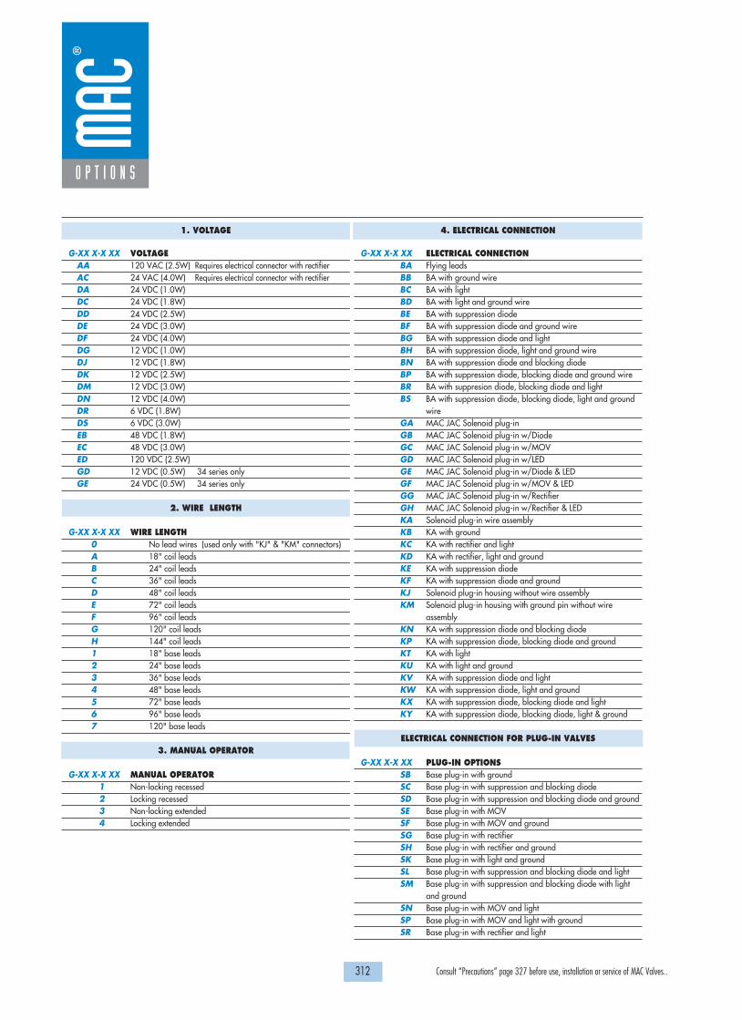
312 Consult “Precautions” page 327 before use, installation or service of MAC Valves..
O P T I O N S
1. VOLTAGE
G-XX X-X XX VOLTAGEAA 120 VAC (2.5W) Requires electrical connector with rectifierAC 24 VAC (4.0W) Requires electrical connector with rectifierDA 24 VDC (1.0W)DC 24 VDC (1.8W)DD 24 VDC (2.5W)DE 24 VDC (3.0W)DF 24 VDC (4.0W)DG 12 VDC (1.0W)DJ 12 VDC (1.8W)DK 12 VDC (2.5W)DM 12 VDC (3.0W)DN 12 VDC (4.0W)DR 6 VDC (1.8W)DS 6 VDC (3.0W)EB 48 VDC (1.8W)EC 48 VDC (3.0W)ED 120 VDC (2.5W)GD 12 VDC (0.5W) 34 series onlyGE 24 VDC (0.5W) 34 series only
2. WIRE LENGTH
G-XX X-X XX WIRE LENGTH0 No lead wires (used only with "KJ" & "KM" connectors)A 18" coil leadsB 24" coil leadsC 36" coil leadsD 48" coil leadsE 72" coil leadsF 96" coil leadsG 120" coil leadsH 144" coil leads1 18" base leads2 24" base leads3 36" base leads4 48" base leads5 72" base leads6 96" base leads7 120" base leads
3. MANUAL OPERATOR
G-XX X-X XX MANUAL OPERATOR1 Non-locking recessed2 Locking recessed3 Non-locking extended4 Locking extended
4. ELECTRICAL CONNECTION
G-XX X-X XX ELECTRICAL CONNECTIONBA Flying leadsBB BA with ground wireBC BA with lightBD BA with light and ground wireBE BA with suppression diodeBF BA with suppression diode and ground wireBG BA with suppression diode and lightBH BA with suppression diode, light and ground wireBN BA with suppression diode and blocking diodeBP BA with suppression diode, blocking diode and ground wireBR BA with suppresion diode, blocking diode and lightBS BA with suppression diode, blocking diode, light and ground
wireGA MAC JAC Solenoid plug-inGB MAC JAC Solenoid plug-in w/DiodeGC MAC JAC Solenoid plug-in w/MOV GD MAC JAC Solenoid plug-in w/LEDGE MAC JAC Solenoid plug-in w/Diode & LEDGF MAC JAC Solenoid plug-in w/MOV & LEDGG MAC JAC Solenoid plug-in w/RectifierGH MAC JAC Solenoid plug-in w/Rectifier & LEDKA Solenoid plug-in wire assemblyKB KA with groundKC KA with rectifier and lightKD KA with rectifier, light and groundKE KA with suppression diodeKF KA with suppression diode and groundKJ Solenoid plug-in housing without wire assemblyKM Solenoid plug-in housing with ground pin without wire
assemblyKN KA with suppression diode and blocking diodeKP KA with suppression diode, blocking diode and groundKT KA with lightKU KA with light and groundKV KA with suppression diode and light KW KA with suppression diode, light and groundKX KA with suppression diode, blocking diode and lightKY KA with suppression diode, blocking diode, light & ground
ELECTRICAL CONNECTION FOR PLUG-IN VALVES
G-XX X-X XX PLUG-IN OPTIONSSB Base plug-in with groundSC Base plug-in with suppression and blocking diodeSD Base plug-in with suppression and blocking diode and groundSE Base plug-in with MOVSF Base plug-in with MOV and groundSG Base plug-in with rectifierSH Base plug-in with rectifier and groundSK Base plug-in with light and groundSL Base plug-in with suppression and blocking diode and lightSM Base plug-in with suppression and blocking diode with light
and groundSN Base plug-in with MOV and lightSP Base plug-in with MOV and light with groundSR Base plug-in with rectifier and light

313 Consult “Precautions” page 327 before use, installation or service of MAC Valves..
O P T I O N S
Codification table for voltages / Manual operators / Electrical connections
- Solenoid valves 52 & 400 Series
OPTIONS AVAILABLE FOR
-GM- G XX X-X XX1 2 3 4
VALVE CODE �

314 Consult “Precautions” page 327 before use, installation or service of MAC Valves..
O P T I O N S
1. VOLTAGE
G-XX X-X XX VOLTAGEDC 24 VDC (1.8 W)DD 24 VDC (2.5 W)DE 24 VDC (3.0 W)DF 24 VDC (4.0 W)DJ 12 VDC (1.8 W)DK 12 VDC (2.5 W)DM 12 VDC (3.0 W)DN 12 VDC (4.0 W)
2. WIRE LENGTH
G-XX X-X XX WIRE LENGTH0 No lead wire (use only with "KJ" & "KM" elecrical
connectors)
A 18"B 24"C 36"D 48"E 72"F 96"G 120"H 144"
3. MANUAL OPERATOR
G-XX X-X XX MANUAL OPERATOR1 Non-locking recessed2 Locking recessed3 Non-locking extended4 Locking extended
4. ELECTRICAL CONNECTION
G-XX X-X XX ELECTRICAL CONNECTIONBA Flying leadsBB BA with ground wireBC BA with light parallel to leadsBD BA with light parallel to leads & ground wireBE BA with suppression diodeBF BA with suppression diode & ground wireBG BA with suppression diode plus light parallel to leadsBH BA with suppression diode plus light parallel to leads &
ground wire
*BN BA with suppression diode plus blocking diode*BP BA with suppression diode plus blocking diode & ground
wire
*BR BA with suppression diode plus blocking diode & lightparallel to leads
*BS BA with suppression diode plus blocking diode & lightparallel to leads & ground wire
BT BA with light on topBU BA with light on top & ground wireBV BA with suppression diode plus light on topBW BA with suppression diode plus light on top & ground wire*BX BA with suppression diode plus blocking diode & light on top*BY BA with suppression diode plus blocking diode & light on
top & ground wire
G-XX X-X XX SOLENOID PLUG-IN CONNECTOR WITH LEADSGA MAC JAC Solenoid plug-inGB MAC JAC Solenoid plug-in w/DiodeGC MAC JAC Solenoid plug-in w/MOV GD MAC JAC Solenoid plug-in w/LEDGE MAC JAC Solenoid plug-in w/Diode & LEDGF MAC JAC Solenoid plug-in w/MOV & LEDGG MAC JAC Solenoid plug-in w/RectifierGH MAC JAC Solenoid plug-in w/Rectifier & LEDKA Plug-in wire assemblyKB KA with ground wireKE KA with suppression diodeKF KA with suppression diode & ground wireKJ Plug-in housing without wire assembly
('KA' without wire assembly)
KM Plug-in housing without wire assembly ('KB' without wire assembly)
*KN KA with suppression diode plus blocking diode*KP KA with suppression diode plus blocking diode & ground wireKT KA with light on topKU KA with light on top & ground wireKV KA with suppression diode plus light on topKW KA with suppression diode plus light & ground wire*KX KA with suppression diode plus blocking diode & light on top*KY KA with suppression diode plus blocking diode & light on
top & ground wire
Note: Blocking diode is located in the lead wire

315 Consult “Precautions” page 327 before use, installation or service of MAC Valves..
O P T I O N S
Codification table for voltages / Manual operators / Electrical connections
- Solenoid valves 37 & 47 Series
OPTIONS AVAILABLE FOR
H XX X-X XX1 2 3 4
VALVE CODE �

316 Consult “Precautions” page 327 before use, installation or service of MAC Valves..
O P T I O N S
1. VOLTAGE
H-XX X-X XX VOLTAGEAA 120/50, 120/60 (6.7 W)
(use connector with rectifier)
AB 220/50, 220/60 (5.6 W)(use connector with rectifier)
AC 240/50, 240/60 (5.8 W)(use connector with rectifier)
AD 24/50, 24/60 (7.8 W)(use connector with rectifier)
DA 24 VDC (5.2 W)DB 24 VDC (2.4 W)DC 24 VDC (1.8 W)DD 24 VDC (1.0 W)DF 12 VDC (5.2 W)DG 12 VDC (2.4 W)DH 12 VDC (1.8 W)DJ 12 VDC (1.0 W)DL 120 VDC (6.3 W)
2. WIRE LENGTH
H-XX X-X XX WIRE LENGTH0 No lead wire (use with "MJ, MM & K Type connectors)A 18"B 24"C 36"D 48"E 72"F 96"G 120"H 144"
3. MANUAL OPERATOR
H-XX X-X XX MANUAL OPERATOR0 No operator1 Non-locking recessed2 Locking recessed3 Non-locking extended4 Locking extended
4. ELECTRICAL CONNECTION
H-XX X-X XX ELECTRICAL CONNECTIONBA Flying leadsBB BA with ground wireBC BA with lightBD BA with light & ground wireBE BA with suppression diodeBF BA with suppression diode & ground wireBG BA with suppression diode plus lightBH BA with suppression diode plus light & ground wire*BN BA with suppression diode plus blocking diode*BP BA with suppression diode plus blocking diode & ground wire*BR BA with suppression diode plus blocking diode & light*BS BBA with suppression diode plus blocking diode & light &
ground wire
BK BA with full wave rectifier
H-XX X-X XXBL BA with full wave rectifier & ground wireBT BA with full wave rectifier plus lightBU BA with full wave rectifier plus light & ground wire
H-XX X-X XX PLUG-IN CONNECTORFA Base plug-inFB FA with ground wireFC FA with lightFD FA with light & ground wireFE FA with suppression diodeFF FA with suppression diode & ground wireFG FA with suppression diode & lightFH FA with suppression diode plus light & ground wireFK FA with full wave rectifierFL FA with full wave rectifier & ground wire*FN FA with suppression diode plus blocking diode*FP FA with suppression diode plus blocking diode & ground wire*FR FA with suppression diode plus blocking diode plus light*FS FA with suppression diode plus blocking diode & light &
ground wire
FT FA with full wave rectifier plus lightFU FA with full wave rectifier plus light & ground wireMA Solenoid plug-in wire assemblyMB MA with ground wireMC MA with lightMD MA with light & ground wireME MA with suppression diodeMF MA with suppression diode & ground wireMG MA with suppression diode plus lightMH MA with suppression diode plus light & ground wireMK MA with full wave rectifierML MA with full wave rectifier & ground wire*MN MA with suppression diode plus blocking diode*MP MA with suppression diode plus blocking diode & ground wire*MR MA with suppression diode plus blocking diode & light*MS MA with suppression diode plus blocking diode & light &
ground wire
MT MA with full wave rectifier plus lightMU MA with full wave rectifier plus light & ground wireMJ Plug-in housing without wire assembly ('MA' option
without wire assembly)MM Plug-in housing without wire assembly ('MB' option
without wire assembly)KA Mini square connectorKB KA with suppression diodeKC KA with M.O.V.KD KA with lightKE KA with light & suppression diodeKF KA with light & M.O.V.KJ Mini square connector – male onlyKK KJ with suppression diodeKL KJ with M.O.V.KM KA with full wave rectifierKN KA with full wave rectifier & M.O.V.KP KA with full wave rectifier & lightKR KA with full wave rectifier plus light & M.O.V.KS KJ with full wave rectifier
* Blocking diode is located in the lead wire

317 Consult “Precautions” page 327 before use, installation or service of MAC Valves..
O P T I O N S
Codification table for voltages / Manual operators / Electrical connections
- Solenoid valves 36, 46, ISO 01 and ISO 02 Series
OPTIONS AVAILABLE FOR
J XX X-X XX1 2 3 4
VALVE CODE �

318 Consult “Precautions” page 327 before use, installation or service of MAC Valves..
O P T I O N S
1. VOLTAGE
J-XX X-X XX VOLTAGEAA 120VAC (5.4W)AC 24VAC (5.4W)DE 24VDC (1.8W)DF 12VDC (1.8W)DJ 24VDC (1.3W)DL 12VDC (1.3W)DR 12VDC (1.0W)*DU 24VDC (1.0W)*
* Not available on 36 series universal valve
2. WIRE LENGTH
J-XX X-X XX WIRE LENGTHA 18" coil leadsB 24" coil leadsC 36" coil leadsD 48" coil leadsE 72" coil leadsF 96" coil leadsP Base plug-inO No leads (use with J, K & L type connectors)
3. MANUAL OPERATOR
J-XX X-X XX MANUAL OPERATOR0 No operator1 Non-locking recessed2 Locking recessed3 Non-locking extended4 Locking extended
4. ELECTRICAL CONNECTION
CONNECTORS FOR NON PLUG-IN VALVESJ-XX X-X XX ELECTRICAL CONNECTION
BA Flying leadsGA MAC JAC solenoid plug-inGB MAC JAC solenoid plug-in with diodeGC MAC JAC solenoid plug-in with MOVGD MAC JAC solenoid plug-in with lightGE MAC JAC solenoid plug-in with diode and lightGF MAC JAC solenoid plug-in with MOV and lightGG MAC JAC solenoid plug-in with recti�erGH MAC JAC solenoid plug-in with recti�er and lightGJ MAC JAC solenoid plug-in – Male onlyGK MAC JAC solenoid plug-in with diode – Male onlyGL MAC JAC solenoid plug-in with MOV – Male onlyGM MAC JAC solenoid plug-in with light – Male onlyGN MAC JAC solenoid plug-in with diode and light – Male onlyGP MAC JAC solenoid plug-in with MOV and light – Male onlyGR MAC JAC solenoid plug-in with recti�er – Male onlyGS MAC JAC solenoid plug-in with recti�er and light – Male only
*JA Square Connector*JC Square Connector with light*JE Square Connector with diode*JF Square Connector with MOV*JG Square Connector with diode/light*JH Square Connector with MOV /light*JK Square Connector with Recti�er
J-XX X-X XX*JL Square Connector with Recti�er with light*JJ Square Connector Male only (Plain)*JB Rectangular Connector*JD Rectangular Connector with light*JN Rectangular Connector with diode*JP Rectangular Connector with MOV*JR Rectangular Connector with diode/light*JS Rectangular Connector with MOV /light*JT Rectangular Connector with Recti�er*JU Rectangular Connector with Recti�er with light*JM Rectangular Connector Male only (Plain)
* Not available on manifold or stacking valves
CONNECTORS FOR NON PLUG-IN VALVESJ-XX X-X XX MINI SQUARE PLUG-IN CONNECTORS
9.4 MM SPACING BETWEEN PINSKA Mini plug-inKB Mini plug-in with diodeKC Mini plug-in with MOVKD Mini plug-in with lightKE Mini plug-in with diode and lightKF Mini plug-in with MOV and lightKG Mini plug-in with recti�erKH Mini plug-in with recti�er and lightKJ Mini plug-in – Male onlyKK Mini plug-in with diode - Male onlyKL Mini plug-in with MOV - Male onlyKM Mini plug-in with light - Male onlyKN Mini plug-in with diode and light – Male onlyKP Mini plug-in with MOV and light – Male onlyKR Mini plug-in with recti�er – Male onlyKS Mini plug-in with recti�er and light – Male only
CONNECTORS FOR NON PLUG-IN VALVESJ-XX X-X XX MINI SQUARE PLUG-IN CONNECTORS
8.0 MM SPACING BETWEEN PINSISO SPECIFICATION 15217
LA Mini plug-inLB Mini plug-in with diodeLC Mini plug-in with MOVLD Mini plug-in with lightLE Mini plug-in with diode and lightLF Mini plug-in with MOV and lightLG Mini plug-in with recti�erLH Mini plug-in with recti�er and lightLJ Mini plug-in – Male onlyLK Mini plug-in with diode - Male onlyLL Mini plug-in with MOV - Male onlyLM Mini plug-in with light - Male onlyLN Mini plug-in with diode and light – Male onlyLP Mini plug-in with MOV and light – Male onlyLR Mini plug-in with recti�er – Male onlyLS Mini plug-in with recti�er and light – Male only
J-XX X-X XX CONNECTORS FOR PLUG-IN VALVESFA Base plug-inFB Base plug-in with diodeFC Base plug-in with MOVFD Base plug-in with lightFE Base plug-in with diode and lightFF Base plug-in with MOV and lightFG Base plug-in with recti�erFH Base plug-in with recti�er and light

319 Consult “Precautions” page 327 before use, installation or service of MAC Valves..
O P T I O N S
Codification table for voltages / Manual operators / Electrical connections
- Solenoid valves 32, 38, 42, 44, 47 & 48 Series
OPTIONS AVAILABLE FOR
L XX X-X XX1 2 3 4
VALVE CODE �
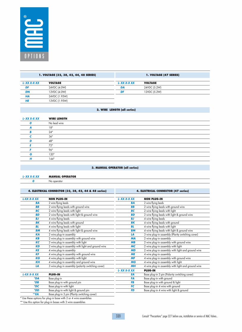
320 Consult “Precautions” page 327 before use, installation or service of MAC Valves..
2. WIRE LENGTH (all series)
L- XX X-X XX WIRE LENGTH
0 No lead wire
A 18"
B 24"
C 36"
D 48"
E 72"
F 96"
G 120"
H 144"
3. MANUAL OPERATOR (all series)
L- XX X-X XX MANUAL OPERATOR
0 No operator
O P T I O N S
1. VOLTAGE (32, 38, 42, 44, 48 SERIES)
L- XX X-X XX VOLTAGE
DF 24VDC (4.0W)
DN 12VDC (4.0W)
HA 24VDC (1.95W)
HE 12VDC (1.95W)
1. VOLTAGE (47 SERIES)
L- XX X-X XX VOLTAGE
DA 24VDC (5.2W)
DF 12VDC (5.2W)
4. ELECTRICAL CONNECTOR (32, 38, 42, 44 & 48 series)
L-XX X-X XX NON PLUG-INBA 2 wire flying leadsBB 2 wire flying leads with ground wireBC 2 wire flying leads with lightBD 2 wire flying leads with light & ground wireBJ 4 wire flying leadsBK 4 wire flying leads with groundBL 4 wire flying leads with lightBM 4 wire flying leads with light & ground wireKA 2 wire plug-in assemblyKB 2 wire plug-in assembly with ground wireKC 2 wire plug-in assembly with lightKD 2 wire plug-in assembly with light and ground wireKE 4 wire plug-in assemblyKF 4 wire plug-in assembly with ground wireKG 4 wire plug-in assembly with lightKH 4 wire plug-in assembly and ground wireLA 3 wire plug-in assembly (polarity switching cover)
L-XX X-X XX PLUG-IN*DA Base plug-in*DB Base plug-in with ground pin*DC Base plug-in with light*DD Base plug-in with light & ground pin
**EA Base plug-in 3 pin (Plarity switching cover)* Use these options for plug-in base with 2 or 4 wire assemblies** Use this option for plug-in bases with 3 wire assemblies
4. ELECTRICAL CONNECTOR (47 series)
L- XX X-X XX NON PLUG-INBA 2 wire flying leadsBB 2 wire flying leads with ground wireBC 2 wire flying leads with lightBD 2 wire flying leads with light & ground wireBJ 4 wire flying leadsBK 4 wire flying leads with groundBL 4 wire flying leads with lightBM 4 wire flying leads with light & ground wireLA 3 wire plug-in assembly (Plarity switching cover)MA 2 wire plug-in assemblyMB 2 wire plug-in assembly with ground wireMC 2 wire plug-in assembly with lightMD 2 wire plug-in assembly with light and ground wireME 4 wire plug-in assemblyMF 4 wire plug-in assembly with ground wireMG 4 wire plug-in assembly with lightMH 4 wire plug-in assembly with light and ground wire
L- XX X-X XX PLUG-INEA Base plug-in 3 pin (Polarity switching cover)FA Base plug-in with groundFB Base plug-in with ground & lightFC Base plug-in 4 wire with groundFD Base plug-in 4 wire with light & ground

321 Consult “Precautions” page 327 before use, installation or service of MAC Valves..
O P T I O N S
Codification table for voltages / Manual operators / Electrical connections
- Solenoid valves 33 Series
OPTIONS AVAILABLE FOR
R XX X-X XX1 2 3 4
VALVE CODE �

322 Consult “Precautions” page 327 before use, installation or service of MAC Valves..
O P T I O N S
1. VOLTAGE
R-XX X-X XX VOLTAGE
DA 24 VDC (0.5W)
DB 24 VDC (1.0W)
DC 24 VDC (1.8W)
DD 24 VDC (2.5W)
DE 24 VDC (3.0W)
DF 24 VDC (4.0W)
DG 12 VDC (0.5W)
DH 12 VDC (1.0W)
DJ 12 VDC (1.8W)
DK 12 VDC (2.5W)
DL 12 VDC (3.0W)
DM 12 VDC (4.0W)
EA* 24 VDC (60W)
EB* 24 VDC (90W)
EC* 24 VDC (230W)
2. WIRE LENGTH (all series)
R-XX X-X XX WIRE LENGTH
0** No lead wire
A 18"
B 24"
C 36"
D 48"
E 72"
F 96"
G 120"
H 144"
3. MANUAL OPERATOR
R-XX X-X XX MANUAL OPERATOR
0 No operator
1 Non-locking recessed
3 Non-locking extended
4. ELECTRICAL CONNECTOR
R-XX X-X XX NON PLUG-INBA Flying leadsBB Flying leads with LEDBC Flying leads with MOVBD Flying leads with LED and MOVRA Mini JAC solenoid plug-inRB Mini JAC solenoid plug-in with LEDRC Mini JAC solenoid plug-in with MOVRD Mini JAC solenoid plug-in with LED and MOVTA JST solenoid plug-inTB JST solenoid plug-in with LEDTC JST solenoid plug-in with MOVTD JST solenoid plug-in with LED and MOV
*MOD numbers required for these voltages (consult factory) ** Not available for flying leads connector

323 Consult “Precautions” page 327 before use, installation or service of MAC Valves..
S e c t i o n 7 Supplementa l t echn ica l in format ion

324 Consult “Precautions” page 327 before use, installation or service of MAC Valves..
Technical Info
MAC’s PATENDED LATCHING SOLENOID – Eliminates one Solenoid, Simplifies Wiring, Reduces Package Size
MAC’s latching solenoid technology provides the function of a double solenoid operated valve utilizing only one solenoid.
Typical 2 position direct operated double solenoid valves use two solenoids with spool/bore technology. When the power is removedfrom either solenoid, the spool position and valve function is maintained.
With direct acting solenoid valves, poppets with their inherent short strokes are not typically used as they cannot maintain sealingposition when both solenoids are deenergized. As a consequence, longer stroking spool type solenoid valves are used which results inlower shifting forces. MAC’s latching solenoid technology eliminates the sealing issue with poppets when no electrical signal isapplied, by maintaining solenoid force, ensuring adequate sealing, while using short stroking poppets resulting in high shifting forces.
MAC’s latching solenoid only requires one solenoid and correspondingly one plug-in and one conduit wireway verus two forconventional double solenoid valve, saving space, weight and cost. An added benefit of a latching solenoid valve when mounted ona circuit bar is the additional option of side cylinder ports.
HOW IT WORKS
Unlike a spool and bore valve, a poppet valve requires that a force be continuously applied to either end of the poppet to ensure that proper sealing occurs. Ifanother solenoid was simply added to the valve to create a double solenoid valve, power would need to be constantly applied to either solenoid for the valve tofunction properly (see Figure 1). If the poppet valve is converted to a spool and bore type valve design, the longer stroke of the spool and solenoid would resultin lower net shifting forces (see Figure 2), compromising the valves shifting reliability.
The latching solenoid overcomes these problems by introducing a powerfulpermanent magnet armature assembly which magnetically latches itself tothe pole piece and in turn keeps the poppet sealed against the conicalseats when the power is removed from the solenoid. To shift the poppet inthe opposite direction, the polarity of the voltage applied to the solenoidleads is reversed and the attractive force between the permanent magnetarmature assembly and the pole piece is reduced. The return spring in thevalve then shifts the poppet to its other sealing position and the permanentmagnet armature assembly is then magnetically attracted to the upper latch.The upper latch prevents the permanent magnet armature assembly fromattracting itself back to the pole piece when the voltage is removed.Reversing the polarity again to the solenoid lead wires will create apowerful attractive force between the permanent magnet armature assemblyand the pole piece and away from the upper latch which willcorrespondingly move the poppet to the other shifted position.
Solenoid Poppet Solenoid Solenoid Spool Solenoid
Long Solenoid Stroke
Cyl A
Exh A Exh BInlet
Cyl B
Armature
Coil
Push PinConical Seat(cushioning) Poppet
Circuit Board Upper Latch Lower Latch Pole Piece Valve Spring
Figure 1 : Double Solenoid Poppet Figure 2 : Double Solenoid Spool Design
Figure 3 : Latching Solenoid Design

325 Consult “Precautions” page 327 before use, installation or service of MAC Valves..
Technical Info
+
-
SOLENOID "A"
+
-
SOLENOID "B"
WIRING SCHEMATIC FORDOUBLE SOLENOID
Figure 4 : Conventional Double Solenoid
WIRING INSTRUCTIONS AND OPTIONS
As shown in Figure 4, a conventional double solenoid valve requires that the pair of lead wires from each solenoid be wired to an appropriate voltage source,MAC's latching solenoid technology has the option of being wired in one of the three (3) currently available methods.
FOUR WIRE As shown in Figure 5, the four wire method enablesthe coil to be wired as if it were a conventionaldouble solenoid. By connecting the yellow lead wireto positive voltage and the yellow lead wire withblack stripe to negative, the valve will be open tocylinder port”A”. When positive voltage is supplied tothe red lead wire and negative to the red lead with ablack stripe, the valve will now be open to cylinderport”B”. Since the negative red and yellow lead wiresare internally connected together, the supply voltagefor each pair of yellow and red lead wires must beisolated from the other pair (see diagram). Also,power must not be applied to all four leadssimultaneously or a short circuit condition will occurpossibly damaging the voltage source.
THREE WIREUnlike the two wire method ( see Figure 7) whichrequires the user to provide the polarity switchingcircuitry, the three wire method incorporates thepolarity switching circuitry within the solenoidenclosure ( see Figure 6). The black lead wireprovided must be connected to positive and is usedas a common. When negative voltage is suppliedto the yellow lead wire with a black stripe the valvewill be open to cylinder port ”A”. When thenegative voltage is removed from the yellow leadwire with the black stripe and supplied to the redlead wire with a black stripe, the valve will now beopen to cylinder port “B”. Applying voltage to allthree wires simultaneously or with the wrongpolarity will cause permanent damage to theswitching circuitry in the solenoid cover, and thevalve won’t work.
(+) POS IN A - Yellow
(+) POS IN B - Red
(-) NEG IN AYellow/W/Black Stripe
(-) NEG IN BRed/W/Black Stripe
• No circuit board needed• Wired as conventional double• Must isolate pairs of red and
yellow wires from each other
Red/Black Stripe
Red
Yellow
Yellow/Black Stripe
4 WIRE SCHEMATIC FOR LATCHING
+
-
YELLOW W/BLACK STRIPE
RED W/BLACK STRIPE
BLACK• Switching done on circuitboard within valve
• Do not apply power to all3 wires simultaneously
Red/Black Stripe (-)Neg In Cyl B Operation
Black (+)Positive Common
Yellow/Black Stripe (-)Neg In Cyl A Operation
3 WIRE SCHEMATIC FOR LATCHING
(+) IN A
(-) IN B
(+) COMMON
Figure 5 : Four Wire Latching
Figure 6 : Three Wire Latching

326 Consult “Precautions” page 327 before use, installation or service of MAC Valves..
Technical Info
TWO WIREThe two wire method shown in Figure 7, provides a black and red lead wire connectedto the solenoid. The user must provide the polarity switching circuitry to these leads inorder to shift the valve to its two positions. By applying positive DC voltage to the redlead wire and negative to the black, the valve will be open to cylinder port “A”. Whenthe polarity of the voltage is externally reversed to the lead wires the valve will nowbecome open to cylinder port “B”.
AVAILABLE OPTIONS
The 2 and 4 wire connections are available in both a flying lead and plug-in cover. The 3 wire connection is only available in the plug-in style cover. All 2 and 4wire cover options are available with an LED indicator. The LED indicator on a 3 wire cover is standard. The LED will illuminate red for cylinder “A” operationand green for cylinder “B” operation.
The 3 wire connection must be used for valves connected to either a multi-pin connector or a serial manifold. Mixing single solenoids with latching solenoids on acircuit bar is possible since each station of the bar is wired for a latching coil. The circuit bar must be ordered with this wiring configuration. If required, anegative common 3 wire connection is also available, please consult factory.
HOW TO ORDER
The numbering system for a latching solenoid differs from the numbering system for a single solenoid valve. The letter “L” within the model number indicates alatching solenoid, while the letter “G” or "H" in the same position of the model number indicates a single solenoid valve.
• No circuit board needed• Customer must switch polarity of voltage• Red to Positive and Black to Negative yields
flow to cylinder port A• Red to Negative and Black to Positive yields
flow to cylinder port B
Red
Black
Figure 7 : Two Wire Latching

PRECAUTIONS AND WARNINGSCONCERNING THE APPLICATION, INSTALLATION AND SERVICE OF MAC VALVES AND OTHER MAC VALVES PRODUCTS
The warnings and precautions below are important to be read and understood beforedesigning into a system any MAC Valves products, and before installing or servicing any MAC Valves product. Improper use, installation or servicing of any MAC Valves product in some systems could create a hazard to personnel or equipment. No distinction in importance should be made between the terms warnings and precautions.
WARNING : .Under no circumstances are MAC Valves products to be used in any application or in any manner where failure of the MAC Valves product to operate as intended could in any way jeopardize the safety of the operator or any other person or property. • Do not operate outside of pressure range listed on a valve label or outside of the designated
temperature range.• Air supply must be clean and dry. Moisture or contamination can affect proper operation of the
valve.• Before attempting to repair, adjust or clean a MAC Valves product, consult catalog, parts & operation
sheet, or factory for proper maintenance procedures, lubrication and cleaning agents. Never attempt to repair or perform other maintenance with air pressure to the valve.
• If air line lubrication is used do not use any lubrication other than those recommended in the catalog, parts & operation sheet or by the factory.
APPLICATION PRECAUTIONS : .INDUSTRIAL USE -• MAC Valve products are intended for general use in industrial pneumatic and/or vacuum systems.
They are general purpose industrial products with literally thousands of different applications in industrial systems. These products are not inherently dangerous, but they are only a component of an overall system. The system in which they are used must provide adequate safeguards to prevent injury or damage in the event failure occurs, whether it be failure of switches, regulators, cylinders, valves or any other component.
POWER PRESSES -MAC Valve products are not designed nor intended to be used to operate and/or control the operation of clutch and/or brake systems on power presses. There are special products on the market for such use.
2-POSITION VALVES -Some MAC valves are 2-position, 4-way valves. When air is supplied to the inlet port(s) of these valves, there will always be a flow path from the inlet to one of the outlets regardless of which of the two positions the valve is situated. Therefore, if pressurized air retained in the system would present a hazard in the application or servicing of the valve or system, a separate method in the system must be provided to remove the trapped air.
3- POSITION VALVES-Some MAC valves are 3-position, 4-way valves. These valves are either double solenoid or double remote air operated.If either of the two operators is in control, air supplied to the inlet port(s) will pass through the valve to one of the outlets as on 2-position, 4-way valves. However, if neither operator is in control, the valve moves to a center position. Listed below are the various center position functions :
A. CLOSED CENTER- With this type valve, when in the center position all ports are blocked (inlets and exhausts) meaning the air at both outlet ports is trapped. If trapping the air in both outlet ports would present a hazard in the application or servicing, a separate method in the system must be provided to remove the trapped air or this type valve should not be used.
B. OPEN CENTER- With this type valve, when in the center position, the inlet port(s) is blocked and the two outlet ports are open to the exhaust port(s) of the valve. If having no air in either outlet port would present a hazard in the application or servicing, this type valve should not be used.
C. PRESSURE CENTER- With this type valve, when in the center position, the inlet port(s) is connected to both outlet ports of the valve. If having pressurized air to either or both outlet ports would present a hazard in the application or servicing of the valve or system, a separate method in the system must be provided to remove the retained air or this type valve should not be used.
OPERATING SPECIFICATIONS -MAC Valves products are to be installed only on applications that meet all operating specifications described in the MAC catalog for the MAC Valves product.
MANUAL OPERATORS-Most MAC valves can be ordered with manual operators. Manual operators when depressed, are designed to shift the valve to the same position as would the corresponding solenoid or remote air pilot operator if it were activated. Care must be taken to order a type, if any, that will be safe for the physical location of the manual operator in the system. If intentional or accidental operation of a valve by a manual operator could cause personal injury or property damage, a manual operator should not be used.
REMOTE AIR OPERATED VALVESPilot valves supplying signal pressure to remote air operated valves should be 3-way valves with adequate supply and exhaust capacity to provide positive pressurizing and exhausting of the pilot supply line. Pilot lines should be open to exhaust when valves are deenergized.
INSTALLATION PRECAUTIONS : .A. Do not install any MAC Valves product without first turning off air (bleed system completely) and
electricity to the machine.B. MAC Valves products should only be installed by qualified, knowledgeable personnel who
understand how the specific valve is to be pneumatically piped and electrically connected (where applicable). Flow paths through the valve are shown in the catalog and on the valve by use of ANSI or ISO type standard graphic symbols. Do not install unless these symbols and the valve functions and operations are thoroughly understood.
C. If air line lubrication is used do not use any lubrication other than those recommended in the catalog, parts & operation sheet or by the factory.
SERVICE PRECAUTIONS :A. Do not service or remove from service any MAC Valves product without first shutting off both the
air and electricity to the valve and making certain no pressurized air which could present a hazard is retained in the system.
B. MAC Valves products should only be serviced or removed from service by qualified, knowledgeable personnel who understand how the specific product is used and/or how the specific valve is piped and used and whether there is air retained in the connecting lines to the valve or electric power still connected to the valve.
C. Before attempting to repair, adjust or clean a MAC Valves product, consult catalog, parts & operation sheet, or factory for proper maintenance procedures, lubrication and cleaning agents. Never attempt to repair or perform other maintenance with air pressure to the valve.
D. MAC Valves products are never to be stepped on while working on a machine. Damage to a MAC valve, or other product or lines to the product (either air or electrical lines) or accidental activation of a manual operator on the valve could result in personal injury or property damage.
LIMITATION OF GUARANTEE .This Guarantee is limited to the replacement or rebuilding of any valve or other product which should fail to operate properly. Valves or other products, under the MAC Guarantee, must be returned (with or without bases) transportation prepaid and received at our factory within the Guarantee period. They will be returned to the customer at the expense of MAC Valves, Inc., and will carry the same guarantee as provided under the Flat Rate Rebuild Program.
DISCLAIMER OF GUARANTEE .No claims for labor, material, time, damage, or transportation are allowable nor will any valve or other product be replaced or rebuilt under this guarantee which has been damaged by the purchaser not in the normal course of its use and maintenance during the warranty period. The guarantee does not apply to loss or damage caused by fire, theft, riot, explosion, labor dispute, act of God, or other causes beyond the control of MAC Valves,Inc. MAC Valves, Inc. shall in no event be liable for remote, special or consequential damages under the MAC Guarantee, nor under any implied warranties, including the implied warranty of merchantability.
The above Guarantee is our manner of extending the engineering and service resources of the MAC Valves, Inc. organization to assure our customer long, and continued satisfaction.
327

MAC VALVES Warranty, Warranty Limitations, Flat Rate Rebuild Program
M A C V a l v e s P r o d u c t W a r r a n t y I n f o r m a t i o n
The MAC Valves organization has established a reputation over many years for fulfilling the needs and requirements of the users of its products. All MAC Valves are quality products specifically designed and built for long and rugged service. For this reason, MAC Valves is able to provide the Buyer a limited warranty.
WARRANTY: MAC Valves, Inc. hereby warrants to Buyer that, for a period of 18 months from the original date of shipment of each valve from our factory (“Warranty Period”), such valve will be free from significant defects in material and workmanship and will conform to all specifications agreed to by MAC Valves, Inc.. In addition, MAC Valves, Inc. warrants that the electrical coils on such valves will be free from significant defects in material and workmanship for their normal useful life. EXCEPT FOR THESE LIMITED WARRANTIES, MAC VALVES, INC. EXPRESSLY DISCLAIMS ALL REPRESENTATIONS AND WARRANTIES OF ANY KIND (WHETHER EXPRESS, IMPLIED OR ARISING BY OPERATION OF LAW) WITH RESPECT TO THE VALVES, INCLUDING, WITHOUT LIMITATION, ANY WARRANTIES OR REPRESENTATIONS AS TO MERCHANTABILITY, FITNESS FOR A PARTICULAR PURPOSE OR ANY OTHER MATTER. THIS SECTION SURVIVES THE EXPIRATION, TERMINATION OR CANCELLATION OF ANY AGREEMENTS BETWEEN THE PARTIES RELATING TO THE PURCHASE OF THE VALVES.
WARRANTY LIMITATIONS: This Warranty does not apply where the valves have been (i) subjected to abuse, misuse, damage, neglect, negligence, accident, improper testing, improper installation, improper storage, improper handling, abnormal physical stress, abnormal environmental condition, or use contrary to any instructions issued by MAC Valves, Inc.; (ii) modified, reconstructed, repaired, or altered by persons other than MAC Valves, Inc. or its authorized representative; or (iii) used with any third-party product, hardware, software or other product that has not been previously approved in writing by MAC Valves, Inc. Additionally, this Warranty does not cover claims for labor, material, time or transportation, and does not apply to loss or damage caused by fire, theft, riot, explosion, labor dispute, act of God, or other causes beyond the control of MAC Valves, Inc.
EXCLUSIVE REMEDY: The Buyer’s sole remedy under this Warranty is limited to the replacement or rebuilding of any valve which does not conform to the warranties provided herein or, in MAC Valves, Inc.’s sole discretion, refund of the purchase price for the non-conform-ing valve. Buyer’s remedy is conditioned on Buyer’s compliance with its obligations under this Warranty. Valves that Buyer believes do not conform to this Warranty must be returned (with or without bases) transportation prepaid and received at our factory within the Warranty Period. If MAC Valves, Inc. determines that the valve is non-conforming and is otherwise covered by this Warranty, the rebuilt or replaced valve will be returned to the customer at the expense of MAC Valves, Inc., and will carry the same warranties as provided under the Flat Rate Rebuild Program described below. MAC VALVES, INC. WILL NOT BE RESPONSIBLE FOR ANY INCIDENTAL, SPECIAL, EXEMPLARY OR CONSEQUENTIAL DAMAGES, INCLUDING WITHOUT LIMITATION DIRECT AND INDIRECT LOST PROFITS, REGARDLESS OF WHETHER THOSE DAMAGES WERE FORESEEABLE. THE FLAT REBUILD PROGRAM: Valves no longer covered by the MAC Warranty may be eligible for a one-time rebuild under the MAC Valves, Inc. Flat Rate Rebuild Program. Our constant research and testing program is dedicated to extending the life of our valves and maximizing their reliability under the most adverse conditions. Valves returned under this limited program are completely disassembled, inspected, rebuilt to current operating standards whenever possible, tested and returned within a few weeks for a nominal flat rate charge. All rebuilt valves carry the same warranty described (in our MAC Warranty) for new valves for a warranty period of 90 days from the date of shipment from our factory. Valves that have gone through the one-time rebuild will have been marked with a letter “R” as part of the date stamp (This is an example of a rebuild date stamp from this month E(May)17(Year)Tester Symbol R(Indicates Rebuild). Please note that any valves sent back for subsequent rebuild that have already been through the program previously (indicated by the “R”) will not be eligible for additional rebuild.

328
Notes
. . . . . . . . . . . . . . . . . . . . . . . . . . . . . . . . . . . . . . . . . . . . . . . . . . . . . . . . . . . . . . . . . . . . . . . . . . . . . . . . . . . . . . . . . . . . . . . . . . . . . . . . . . . . . . . . . . . . . . . . . . . . . . .
. . . . . . . . . . . . . . . . . . . . . . . . . . . . . . . . . . . . . . . . . . . . . . . . . . . . . . . . . . . . . . . . . . . . . . . . . . . . . . . . . . . . . . . . . . . . . . . . . . . . . . . . . . . . . . . . . . . . . . . . . . . . . . .
. . . . . . . . . . . . . . . . . . . . . . . . . . . . . . . . . . . . . . . . . . . . . . . . . . . . . . . . . . . . . . . . . . . . . . . . . . . . . . . . . . . . . . . . . . . . . . . . . . . . . . . . . . . . . . . . . . . . . . . . . . . . . . .
. . . . . . . . . . . . . . . . . . . . . . . . . . . . . . . . . . . . . . . . . . . . . . . . . . . . . . . . . . . . . . . . . . . . . . . . . . . . . . . . . . . . . . . . . . . . . . . . . . . . . . . . . . . . . . . . . . . . . . . . . . . . . . .
. . . . . . . . . . . . . . . . . . . . . . . . . . . . . . . . . . . . . . . . . . . . . . . . . . . . . . . . . . . . . . . . . . . . . . . . . . . . . . . . . . . . . . . . . . . . . . . . . . . . . . . . . . . . . . . . . . . . . . . . . . . . . . .
. . . . . . . . . . . . . . . . . . . . . . . . . . . . . . . . . . . . . . . . . . . . . . . . . . . . . . . . . . . . . . . . . . . . . . . . . . . . . . . . . . . . . . . . . . . . . . . . . . . . . . . . . . . . . . . . . . . . . . . . . . . . . . .
. . . . . . . . . . . . . . . . . . . . . . . . . . . . . . . . . . . . . . . . . . . . . . . . . . . . . . . . . . . . . . . . . . . . . . . . . . . . . . . . . . . . . . . . . . . . . . . . . . . . . . . . . . . . . . . . . . . . . . . . . . . . . . .
. . . . . . . . . . . . . . . . . . . . . . . . . . . . . . . . . . . . . . . . . . . . . . . . . . . . . . . . . . . . . . . . . . . . . . . . . . . . . . . . . . . . . . . . . . . . . . . . . . . . . . . . . . . . . . . . . . . . . . . . . . . . . . .
. . . . . . . . . . . . . . . . . . . . . . . . . . . . . . . . . . . . . . . . . . . . . . . . . . . . . . . . . . . . . . . . . . . . . . . . . . . . . . . . . . . . . . . . . . . . . . . . . . . . . . . . . . . . . . . . . . . . . . . . . . . . . . .
. . . . . . . . . . . . . . . . . . . . . . . . . . . . . . . . . . . . . . . . . . . . . . . . . . . . . . . . . . . . . . . . . . . . . . . . . . . . . . . . . . . . . . . . . . . . . . . . . . . . . . . . . . . . . . . . . . . . . . . . . . . . . . .
. . . . . . . . . . . . . . . . . . . . . . . . . . . . . . . . . . . . . . . . . . . . . . . . . . . . . . . . . . . . . . . . . . . . . . . . . . . . . . . . . . . . . . . . . . . . . . . . . . . . . . . . . . . . . . . . . . . . . . . . . . . . . . .
. . . . . . . . . . . . . . . . . . . . . . . . . . . . . . . . . . . . . . . . . . . . . . . . . . . . . . . . . . . . . . . . . . . . . . . . . . . . . . . . . . . . . . . . . . . . . . . . . . . . . . . . . . . . . . . . . . . . . . . . . . . . . . .
. . . . . . . . . . . . . . . . . . . . . . . . . . . . . . . . . . . . . . . . . . . . . . . . . . . . . . . . . . . . . . . . . . . . . . . . . . . . . . . . . . . . . . . . . . . . . . . . . . . . . . . . . . . . . . . . . . . . . . . . . . . . . . .
. . . . . . . . . . . . . . . . . . . . . . . . . . . . . . . . . . . . . . . . . . . . . . . . . . . . . . . . . . . . . . . . . . . . . . . . . . . . . . . . . . . . . . . . . . . . . . . . . . . . . . . . . . . . . . . . . . . . . . . . . . . . . . .
. . . . . . . . . . . . . . . . . . . . . . . . . . . . . . . . . . . . . . . . . . . . . . . . . . . . . . . . . . . . . . . . . . . . . . . . . . . . . . . . . . . . . . . . . . . . . . . . . . . . . . . . . . . . . . . . . . . . . . . . . . . . . . .
. . . . . . . . . . . . . . . . . . . . . . . . . . . . . . . . . . . . . . . . . . . . . . . . . . . . . . . . . . . . . . . . . . . . . . . . . . . . . . . . . . . . . . . . . . . . . . . . . . . . . . . . . . . . . . . . . . . . . . . . . . . . . . .
. . . . . . . . . . . . . . . . . . . . . . . . . . . . . . . . . . . . . . . . . . . . . . . . . . . . . . . . . . . . . . . . . . . . . . . . . . . . . . . . . . . . . . . . . . . . . . . . . . . . . . . . . . . . . . . . . . . . . . . . . . . . . . .
. . . . . . . . . . . . . . . . . . . . . . . . . . . . . . . . . . . . . . . . . . . . . . . . . . . . . . . . . . . . . . . . . . . . . . . . . . . . . . . . . . . . . . . . . . . . . . . . . . . . . . . . . . . . . . . . . . . . . . . . . . . . . . .
. . . . . . . . . . . . . . . . . . . . . . . . . . . . . . . . . . . . . . . . . . . . . . . . . . . . . . . . . . . . . . . . . . . . . . . . . . . . . . . . . . . . . . . . . . . . . . . . . . . . . . . . . . . . . . . . . . . . . . . . . . . . . . .
. . . . . . . . . . . . . . . . . . . . . . . . . . . . . . . . . . . . . . . . . . . . . . . . . . . . . . . . . . . . . . . . . . . . . . . . . . . . . . . . . . . . . . . . . . . . . . . . . . . . . . . . . . . . . . . . . . . . . . . . . . . . . . .
. . . . . . . . . . . . . . . . . . . . . . . . . . . . . . . . . . . . . . . . . . . . . . . . . . . . . . . . . . . . . . . . . . . . . . . . . . . . . . . . . . . . . . . . . . . . . . . . . . . . . . . . . . . . . . . . . . . . . . . . . . . . . . .
. . . . . . . . . . . . . . . . . . . . . . . . . . . . . . . . . . . . . . . . . . . . . . . . . . . . . . . . . . . . . . . . . . . . . . . . . . . . . . . . . . . . . . . . . . . . . . . . . . . . . . . . . . . . . . . . . . . . . . . . . . . . . . .
. . . . . . . . . . . . . . . . . . . . . . . . . . . . . . . . . . . . . . . . . . . . . . . . . . . . . . . . . . . . . . . . . . . . . . . . . . . . . . . . . . . . . . . . . . . . . . . . . . . . . . . . . . . . . . . . . . . . . . . . . . . . . . .
. . . . . . . . . . . . . . . . . . . . . . . . . . . . . . . . . . . . . . . . . . . . . . . . . . . . . . . . . . . . . . . . . . . . . . . . . . . . . . . . . . . . . . . . . . . . . . . . . . . . . . . . . . . . . . . . . . . . . . . . . . . . . . .
. . . . . . . . . . . . . . . . . . . . . . . . . . . . . . . . . . . . . . . . . . . . . . . . . . . . . . . . . . . . . . . . . . . . . . . . . . . . . . . . . . . . . . . . . . . . . . . . . . . . . . . . . . . . . . . . . . . . . . . . . . . . . . .
. . . . . . . . . . . . . . . . . . . . . . . . . . . . . . . . . . . . . . . . . . . . . . . . . . . . . . . . . . . . . . . . . . . . . . . . . . . . . . . . . . . . . . . . . . . . . . . . . . . . . . . . . . . . . . . . . . . . . . . . . . . . . . .
. . . . . . . . . . . . . . . . . . . . . . . . . . . . . . . . . . . . . . . . . . . . . . . . . . . . . . . . . . . . . . . . . . . . . . . . . . . . . . . . . . . . . . . . . . . . . . . . . . . . . . . . . . . . . . . . . . . . . . . . . . . . . . .
. . . . . . . . . . . . . . . . . . . . . . . . . . . . . . . . . . . . . . . . . . . . . . . . . . . . . . . . . . . . . . . . . . . . . . . . . . . . . . . . . . . . . . . . . . . . . . . . . . . . . . . . . . . . . . . . . . . . . . . . . . . . . . .
. . . . . . . . . . . . . . . . . . . . . . . . . . . . . . . . . . . . . . . . . . . . . . . . . . . . . . . . . . . . . . . . . . . . . . . . . . . . . . . . . . . . . . . . . . . . . . . . . . . . . . . . . . . . . . . . . . . . . . . . . . . . . . .
. . . . . . . . . . . . . . . . . . . . . . . . . . . . . . . . . . . . . . . . . . . . . . . . . . . . . . . . . . . . . . . . . . . . . . . . . . . . . . . . . . . . . . . . . . . . . . . . . . . . . . . . . . . . . . . . . . . . . . . . . . . . . . .
. . . . . . . . . . . . . . . . . . . . . . . . . . . . . . . . . . . . . . . . . . . . . . . . . . . . . . . . . . . . . . . . . . . . . . . . . . . . . . . . . . . . . . . . . . . . . . . . . . . . . . . . . . . . . . . . . . . . . . . . . . . . . . .
. . . . . . . . . . . . . . . . . . . . . . . . . . . . . . . . . . . . . . . . . . . . . . . . . . . . . . . . . . . . . . . . . . . . . . . . . . . . . . . . . . . . . . . . . . . . . . . . . . . . . . . . . . . . . . . . . . . . . . . . . . . . . . .
. . . . . . . . . . . . . . . . . . . . . . . . . . . . . . . . . . . . . . . . . . . . . . . . . . . . . . . . . . . . . . . . . . . . . . . . . . . . . . . . . . . . . . . . . . . . . . . . . . . . . . . . . . . . . . . . . . . . . . . . . . . . . . .
. . . . . . . . . . . . . . . . . . . . . . . . . . . . . . . . . . . . . . . . . . . . . . . . . . . . . . . . . . . . . . . . . . . . . . . . . . . . . . . . . . . . . . . . . . . . . . . . . . . . . . . . . . . . . . . . . . . . . . . . . . . . . . .
. . . . . . . . . . . . . . . . . . . . . . . . . . . . . . . . . . . . . . . . . . . . . . . . . . . . . . . . . . . . . . . . . . . . . . . . . . . . . . . . . . . . . . . . . . . . . . . . . . . . . . . . . . . . . . . . . . . . . . . . . . . . . . .
. . . . . . . . . . . . . . . . . . . . . . . . . . . . . . . . . . . . . . . . . . . . . . . . . . . . . . . . . . . . . . . . . . . . . . . . . . . . . . . . . . . . . . . . . . . . . . . . . . . . . . . . . . . . . . . . . . . . . . . . . . . . . . .
. . . . . . . . . . . . . . . . . . . . . . . . . . . . . . . . . . . . . . . . . . . . . . . . . . . . . . . . . . . . . . . . . . . . . . . . . . . . . . . . . . . . . . . . . . . . . . . . . . . . . . . . . . . . . . . . . . . . . . . . . . . . . . .

MAC VALVES, INC.P.O. BOX 11130569 BECK ROADWIXOM, MI 48393-7011
TEL: 1-800-MAC VLVSTEL: 1 (248) 624-7700FAX: 1 (248) 624-0549E-mai l : [email protected] Si te: www.macvalves.com
MAC VALVES EUROPE, INC.RUE MARIE CURIE, 12B-4431 ANS (L IEGE)BELGIUM
TEL: 32 (4) 239 68 68FAX: 32 (4) 263 19 42E-mai l : [email protected]
MAC VALVES PACIFIC, INC.P.O. BOX 12221PENROSE, AUCKLANDNEW ZEALAND
TEL: 64 (9) 634-9400FAX: 64 (9) 634-9401E-mai l : [email protected]
MAC VALVES, INC.5555 ANN ARBOR ROADDUNDEE, MICHIGAN (MI) 48131U.S.A.
TEL: 1 (734) 529-5099FAX: 1 (248) 863-2111
99
9C
TCB
- 0
4/
03