fi · sensing ntc thermistor. the sensor is installed in the sauna room according to the...
TRANSCRIPT

�
FI
Control UnitEN
��0�2007

2
EN
Congratulations on choosing a Fenix control unit by Harvia!With Fenix you can control all functions of your sauna via the user-
prompting touch screen of a wireless control unit. You can control the temperature, humidity, colour lights, and all other aspects – from your couch. A novelty that makes it possible for you to enjoy your sauna in a variety of new ways!
CONTENTS
FENIX WIRELESS CONTROL UNIT .................. 3QUICK GUIDE .............................................. 4FIRST SWITCH-ON ....................................... 4CHOOSING THE PANEL LANGUAGE ............... 4SETTING THE TIME AND DAY ....................... 4CONNECTIONS BETWEEN DEVICES ............... 4DEVICE PAIR-UP .......................................... 4HEATING UP THE SAUNA ............................. 5SETTING THE PRE-SETTING TIME - delayed heating ............................................ 5
1. HARVIA FENIX CONTROL UNIT ................. 6 �.�. General ............................................. 6 �.2. Technical Data ................................... 6 �.3. Configurations ................................... 7
2. INSTRUCTIONS FOR USE .......................... 7 2.�. General ............................................. 7 2.�.�. Batteries ................................. 7 2.2. Function Menus in the Main Menu and Function Icons .................................... 7 2.3. Sauna Time Setup .............................. 8 2.4. Heater and Steamer Setup .................. 8 2.4.�. Heater Setup ........................... 8 2.4.2. Steamer Setup ......................... 8 2.5. Colour Light and Light Setup ............. �0 2.5.�. Colour Light Setup .................. �0 2.5.2. Light Setup ............................ �� 2.6. Fan Setup ....................................... �� 2.7. Week Timer .................................... �2 2.8. User Settings ................................... �3 2.9. Miscellaneous .................................. �4 2.9.�. Statistics ............................... �4
2.9.2. Curve Diagram ....................... �4 2.9.3. Adjust Current Time and Day ... �4 2.9.4. Device Pair-Up ....................... �4 2.9.5. Panel Power Settings .............. �5 2.9.6. Additional Options and Settings �5 2.9.7. Detailed Version Info............... �5 2.9.8. Sensor Reading Adjustment ..... �5 2.9.9. Service Menu ......................... �5 a) Auxiliary Relay Function ................ �5 b) Installed/Enabled Features ............. �5 c) Heater Watts Setup ...................... �5 d) Steamer Watts Setup .................... �5 e) Max On Time Setup ...................... �5 f) Load Factory Settings .................... �5 2.�0. Options ......................................... �5 2.�0.�. Calibrating the Touch Screen . �6
3. INSTRUCTIONS FOR INSTALLATION ........ 18 3.�. Installing the Wireless Control Unit ..... �8 3.2. Installing the Power Unit ................... 20 3.2.�. Electrical Connections of Power Unit SACF�50 for Heater .................. 20 3.2.2. Electrical Connections of Power Unit SACF�65S for Steamer/Heater ... 20 3.2.3. Electrical Installations of Power Unit SACF�00 for Colour Light .......... 20 3.2.4. Installing the Radio Antenna .... 26 3.2.5. Installing the Temperature and Humidity Sensors ....................... 26 3.2.6. Resetting the Overheat Protector ......................................... 27
EN

3
EN
Sauna ON/OFF
Set the Pre-Setting Time
Light ON/OFF
Fan ON/OFF
Colour Light ON/OFF Main Menu
Start Menu
FENIX WIRELESS CONTROL UNIT
Power switch ON/OFF
Fitting and changing the batteries to the wireless control unit, behind the display
Touch screen of the wireless control unit
Function ON
Function icons
Time setting
Function OFF
Heater ON/OFF
Steamer ON/OFF
Active functions
Function Icons
Removing the cover
Replacing the cover
(The displayed view varies according to the features acquired and enabled.)
(The displayed view varies according to the features acquired and enabled.)
The icon in the upper right corner indicates the power source (batteries or charger). It does not indicate what the charge level is or when charging is required.
Short cut to Steamer Settings.
Short cut to Operating Time Settings.
To the Main Menu by pressing the function iconIn Sauna ON mode, you can also switch to Main Menu by pressing the power switch lightly. The link to the Main Menu appears on the screen.
Short cut to Temperature Settings.
The icons in the top row provide short cuts to active functions, for example Colour Light Settings.
Short cut to Weekday and Time Settings.
Short cut to Graph View.
Sauna OFF
Under the Sauna ON/OFF icon you’ll find information on the conditions in your sauna, offering short cuts to change the settings affecting the current sauna bath.

4
EN
Main Menu, page � Main Menu, page 2
Main Menu - Function Menus(The displayed view varies according to the features acquired and enabled.)
Back to the Start MenuPage change
Confirm
Exit/Cancel
Arrow icons
Track bar
Controls in Menus
No connection – this icon is constantly displayed while the connections are disconnected.
Connection active – this icon is displayed while the devices are communicating with each other.
QUICK GUIDE
FIRST SWITCH-ONFirst time when you switch on the wireless control unit, it will automatically prompt you to calibrate the touch screen. The unit will guide you through the calibration process. After this you need to choose the desired panel language and set the day and time. Make the required settings and confirm. If the unit does not follow the above steps automatically, they can be carried out manually:
CALIBRATING THE TOUCH SCREEN (see section 2.10).
CHOOSING THE PANEL LANGUAGE�. Start Menu (the first menu to appear after switching on).2. Press the Main Menu icon. Use the page change to scroll through the Main Menu to User Settings and select. 3. Use the page change to scroll to Panel Language and select.4. Choose a language and Confirm. 5. Press the Exit icon to return to the Start Menu.
SETTING THE TIME AND DAY�. Press the Main Menu icon. Use the page change to scroll through the Main Menu to Miscellaneous and select. 2. Use the page change to scroll to Adjust current time and select.3. Set day and confirm.4. Set time and confirm.
CHOOSING THE DEVICES TO BE ENABLED (see Service menu 2.9.9. b).
CONNECTIONS BETWEEN DEVICESAn icon in the upper left corner of the screen indicates whether the connections are active or whether there are lost connections or new devices to be connected. When connections are lost it can also be a case that the wireless control unit is outside the operating range (ca. �0 m) of the radio link.
Missing connections are established through device pair-up. See the following quick tips or chapter 2.9.4. ‘Device Pair-Up’ (further below).

5
EN
DEVICE PAIR-UPThe following pair-up procedure is necessary to make the devices recognize each other and communicate:�. Switch on the wireless control unit. The Start Menu is displayed. 2. Press the Main Menu icon. Use the page change to scroll through the Main Menu to Miscellaneous and select.3. Use the page change to scroll to Device Pair-Up and select. This is the procedure to be used to establish a connection between devices/device pairs. 4. Under the selected menu item you will find the pair-up procedure menu. When you are establishing connections between device pairs for the first time, select Help. Read through the instructions and follow them. 5. Press the Confirm icon to switch back to the Pair-Up Procedure menu:
A) Click ’New code’, and the display will show ‘ Panel code changed. Renewing pairs is necessary.’ C) Click ’Heater’, and the display will show ‘Linking to Heater, switch power on now.’ D) Turn power unit on within 10 seconds, and the display will show ‘Successful pair-up with heater.’ If the pairing up was not successful, the display will show “Pair-up with heater FAILED”. In this case, return to Step B and repeat the procedure according to the instructions.6. To further add colour light, for example, press ‘Colour light’.NOTE! If you press the ‘New Code’ icon again, all connections are lost and must be re-established!
HEATING UP THE SAUNA�. Start Menu (the first menu to appear after switching on).2. Use the function icons to switch functions on or off. Light ON/OFF, Sauna ON/OFF, Heater ON/OFF, Steamer ON/OFF (model SACF�65S) While an icon is activated, the corresponding function is on. The display shows up-to-date information on your sauna, including the temperature, humidity and remaining operating time. 3. All displayed data can be changed. Go to settings by pressing the relevant reading or the icon up on the screen. Make the desired changes and confirm or cancel to return to the previous screen. Any confirmed changes only affect the current bath. 4. When active icons are deactivated, the corresponding functions are switched off, and the display will show a recap of the most recent sauna bath, including the total time and energy consumption. Touch the screen to return to the Start Menu.
SETTING THE PRE-SETTING TIME - delayed heating�. Press the Set the Pre-Setting Time icon.2. Set the desired Delay after which the heater should start heating up the sauna. Use the arrow icons, which enable an accurate setting, or the track bar. 3. Confirm by pressing the Sauna ON icon or cancel if you wish to make other settings. This takes you back to the Start Menu.4. While the function is activated, the display shows up-to-date information on your sauna, including the temperature, humidity and remaining time to heating. Activate from the current display Heater ON and/or Steamer ON, depending for which function you wish to
set the pre-setting time. 5. To activate other functions, press the displayed function icons, for example Light ON.
Pair-Up Help, page � Pair-Up Help, page 2Pair-Up Procedure
Pair-Up icon for colour light power unit
Pair-Up icon for heater power unit

6
EN
Figure 1. Interconnected devices of a Fenix control unit.
1. HARVIA FENIX CONTROL UNIT
1.1. GeneralHarvia Fenix is a multidimensional control unit that makes it possible for you to enjoy your sauna in a wider variety of ways. The Fenix control unit allows you to totally control your sauna and the bathing conditions, such as the temperature, humidity and ventilation.
The control unit consists of a wireless control unit (touch screen), a power unit/power units and a sensor/sensors. The touch-screen control unit communicates with the power unit wirelessly or, alternatively, via a cable. See Figure �.
The control unit can be used to control sauna heaters and Combi combined heaters/steamers within an output range of 2,3–�5 kW. The Fenix wireless control unit operates to a distance of about �0 metres from the power unit, depending on structural obstacles.
1.2. Technical DataWireless control unit:
Touch screen for controlling the sauna by selecting the desired functions and settings. Equipped with rechargeable batteries. The recharge stand must be placed in a dry place outside the sauna room. See Figure 2.Operating voltage 3,6 V.Temperature adjustment range 40–��0 °C.
•
••
Humidity adjustment range 20–95 % RH.Operating time adjustment range:
family saunas 0,5–6 h, no week timer public saunas in apartment buildings 0,5–�2 h, required pause time min. 6 h. For longer operating times consult the importer/manufacturer.
Pre-setting time adjustment range 0–�8 h.Programmable week timer.Lighting control, max. power �00 W, 230 V �N~Fan control, max. power �00 W, 230 V �N~Colour light control, max. power 2 x 50 W colour light unit �2 V DC.
Power units: Supply voltage 400 V 3N~Max. load �5 kW/400 V 3N~The power units are placed in a dry place outside the sauna room. They must not be embedded within the wall structure.
Sensors:The temperature sensor is equipped with a resettable overheat protector and a temperature-sensing NTC thermistor. The sensor is installed in the sauna room according to the instructions given in chapter 3.2.5. ‘Installing the Temperature and Humidity Sensors’.The humidity sensor measures relative humidity. The sensor is installed in the sauna room according to the instructions given in chapter 3.2.5. ‘Installing the Temperature and Humidity Sensors’.
••
•••
••
•••
•
•

7
EN
1.3. ConfigurationsThe Harvia Fenix control unit consists of different devices which together allow comprehensive control over all aspects of sauna bathing. Available device packages are:
SACF10 wireless control unit for controlling power units, incl.
Touch screen (wireless control unit)Recharge standWall-mounting plate for recharge standCharger3 AA rechargeable batteriesInstructions for installation and use.
SACF150 power unit for controlling heater (max. �5 kW), incl.
Power unit SACF�50 for heater controlRadio antenna and cable for communication with wireless control unitTemperature sensorHumidity sensor (available as an accessory)
SACF165S power unit for controlling combined heater/steamer (max. �6,5 kW), incl.
Power unit SACF�65S for heater/steamer controlRadio antenna and cable for communication with wireless control unitTemperature sensorHumidity sensor
SACF100 power unit for controlling colour light, incl.
Power unit SACF�00 for controlling colour light units max. 2 x 50 WCable for connection to power unit SACF�50 or SACF�65S
2. INSTRUCTIONS FOR USE
Before you switch the heater on check always that there aren’t any things over the heater or in the near distance of the heater.
2.1. GeneralThe wireless control unit is equipped with a user-prompting touch screen and is operated by three AA rechargeable batteries. The unit comes with a recharge stand. The recharge stand can be mounted into the wall or to the table but it must be placed outside the sauna room. Never take the wireless control unit to a heated sauna!
The wireless control unit is activated by pressing the black power switch above the screen. Activation brings the Start Menu with the function icons to the screen. Pressing a function icon switches the corresponding function on or off. Activated functions are indicated by a dark spot in the corner of relevant function icons and by ‘active function’ images above the screen.
The touch screen can be operated using a finger or, for example, the blunt end of a pencil. Avoid pressing the screen unnecessarily hard!
Clean the touch screen from time to time with a cloth or mild alcohol wipe.
••••••
••
••
•
•
••
•
•
2.1.1. BatteriesThe instructions for fitting/changing the batteries can be found on page 59. The Fenix wireless control unit comes with NiMh AA HR6 rechargeable batteries, voltage �,2 V. The rechargeable batteries can be replaced with non-rechargeable AA batteries. Note! Never place the wireless control unit in the recharge stand when fitted with non-rechargeable batteries. Do not use rechargeable and non-rechargeable batteries simultaneously together.
New, unused batteries must be charged uninterruptedly for 24 hours before use. A complete recharge takes �2 hours. It is recommended to keep the wireless control unit in the supplied recharge stand when the unit is not in use – this way the batteries have charge when the unit is needed again.
Never use a damaged charger or battery. Remove the damaged battery from the unit. Dispose of the batteries according to the local regulations (concerning recycling etc.). Do not place batteries in household waste. Remove the batteries before disposing of the unit. Remove the unit from the charger before fitting/changing batteries.
2.2. Function Menus in the Main Menu and Function IconsYou can control all functions of your sauna using the function menus or the function icons.
Function IconsLight, Fan and Colour Light are activated by pressing the relevant function icon on the screen.
Sauna ON/OFFPress the Sauna ON/OFF icon to enable communication between the power unit and the wireless control unit. The wireless control
unit now displays information on the conditions in your sauna, such as temperature and humidity. Should the connection between the power unit and the wireless control unit be lost during the bath, the power unit will nevertheless be able to perform the programmed functions since all the settings remain stored in its memory.
Settings (operating time, temperature, humidity etc.) made in the Sauna ON mode only affect the current bath.
Settings made in the Sauna OFF mode are default settings which are stored in the memory of the wireless control unit.
The Set the Pre-Setting Time icon takes you directly to the screen where you can set the pre-setting time.
Pressing the Main Menu icon brings the function menus to the screen.
Through the Main Menu you can change all the settings related to your sauna. The function menus are explained in detail further below.
The pictures shown in this manual are meant as guidelines only since the screens may vary according to which features have been acquired and enabled for use.
Function icons can be added and removed from the screen. See 2.9.9. ’b) Installed / Enabled Features’.

8
EN From the Main Menu choose
2.3. Sauna Time SetupThrough the Sauna Time Setup menu you can make timer settings for your sauna.
The operating time is the time the heater is on. The pre-setting time is the delay period after which the heater starts heating up the sauna. Do not forget to activate Heater ON and/or Steamer ON icon on the screen, depending for which function you wish to set the pre-setting time.
••
2.4. Heater and Steamer Setup2.4.1. Heater SetupUnder the Heater Setup menu you can set the temperature that the heater is expected to create in the sauna room.
While the AUTO ON icon is activated, the heater will switch on automatically when you press the Sauna ON/OFF icon. To switch on the heater with the AUTO ON icon deactivated, press the Sauna ON icon and then activate the Heater ON/OFF icon.
To keep your sauna in a good condition for longer, it is important that you have it dehumidified after bathing. With Fenix you can do this by leaving the heater on for a desired period at a temperature of 40 oC. Once the function is activated, it will stay on until the setting is changed by the user.
2.4.2. Steamer SetupThe steamer is controlled through the Steamer Setup menu. One of the two modes must be selected:1) In the %RH Mode (%RH = relative humidity expressed as a percentage) the humidity sensor measures the humidity in the sauna room and the wireless control unit controls the steamer so that the humidity level is maintained as close to the set value as possible during the bath.
Set the desired humidity %RH. The sum of the steamer %RH setpoint and the max. heater setup cannot exceed �40.2) The Interval Mode means that the steamer is on and off periodically. Set the desired duration of the two periods: for example the ON period at �40 seconds and the subsequent OFF period at 85 s. Confirm the settings.
While the AUTO ON icon is activated, the steamer will switch on automatically when you press the Sauna ON/OFF icon.

9
EN
ON OFF
From the Main Menu choose
From the Main Menu choose
ON OFF

�0
EN
From the Main Menu choose
2.5. Colour Light and Light SetupThe colour light settings are available only if your Fenix control unit is equipped with the colour light feature. The feature can also be retrofitted.
2.5.1. Colour Light SetupTo activate the colour light in your sauna room, press the Colour Light function icon. If you wish to change the colour light settings, choose Colour Light Setup from the Main Menu.
Colour Light Menu:There are four colours to choose from: blue, red, green, and yellow. You can choose just one colour or cycle all the four colours.
1) To cycle the colours, set the cycle speed determining how long each colour is on at slow, medium, or fast.2) To use just one colour, press Change Colour to choose the desired colour. The colour that is left displayed will stay on.
The Set Brightness icon is used to adjust the brightness of the colour light.
While the AUTO ON icon is activated, the colour light will switch on automatically when your sauna is ready for bathing.
While the AUTO OFF icon is activated, the colour light will switch off automatically after the desired delay period, which can be set at max. 90 minutes.
Colour Light Unit Disabled indicates whether the colour light is in use or not.
enableddisabled

��
EN
Delay, for example25 min
From the Main Menu choose
From the Main Menu choose
2.5.2. Light SetupTo activate the lighting of your sauna, press the Light icon in the Start Menu. If you wish to change the light settings, choose Light Setup from the Main Menu.
Light Menu: While the AUTO ON icon is activated, the lights will switch on automatically when your sauna is ready for bathing.While the AUTO OFF icon is activated, the lights will switch off automatically after the desired delay period, which can be set at max. 90 minutes.
2.6. Fan SetupTo activate the fan of your sauna, press the Fan icon in the Start Menu. If you wish to change the fan settings, choose Fan Setup from the Main Menu. Ventilation Menu:The fan can be set to switch on or off automatically.
While the AUTO ON icon is activated, the fan will switch on automatically when your sauna is ready for bathing. While the AUTO OFF icon is activated, the fan will switch off automatically after the desired delay period, which can be set at max. 90 minutes. If you activate the Interval Mode, the fan will be on and off periodically. Make the necessary ON and OFF settings: for example, set the fan to blow air into the sauna room for a period of 60 seconds (ON) and to switch OFF for the subsequent 60 s.

�2
EN
ON OFF
From the Main Menu choose
2.7. Week Timer Electrical safety regulations allow the week timer feature to be used only in community saunas!
The week timer settings allow you to program a weekly schedule, which is especially handy if you use your sauna regularly every week. Set the desired bathing time for any chosen day – or even every day – of the week.
When the weekly schedule starts, the wireless control unit will be activated even if switched off.
A pause of at least 6 h is required between each two periods created for the Week Timer schedule.
Week Timer Menu:Choose Enable Program to activate all created programs to be run at set times. View Schedule brings to the screen a recap of your weekly schedule if you have created one; if you do not have one, the display shows ‘Week timer program is empty’. You can also change the schedule in this menu.Create New Program Timing
Set the program start time, which is the time you wish to start bathing. Confirm or, if you wish to return to the previous screen, cancel.Set the program ending time and confirm or cancel. Set the day(s). You can set more than one day at the same time.Confirm the settings or press Cancel to return to the previous screen. Set the desired temperature for the programmed period.Set the desired humidity level for the programmed period. Make sure you have the Enable Steamer box ticked.
•
•
•
•
•
•
Confirm the settings or press Cancel to return to the previous screen.
The display now shows a recap of the settings made. Confirm or press Cancel to return to the previous screen.
If you choose View Schedule again after programming, the displayed week timer schedule will contain the period you just programmed. Here you can change the schedule or, for example, remove a schedule without deleting it permanently, meaning that it will remain stored in the memory for later activation. You can also add/create new schedules. See the following pages for examples.
Delete All Periods deletes all the periods created for a week timer schedule. If you choose this option, the display will show a message asking you to confirm that you wish to delete all periods. Confirm or cancel as required.
Check Validation checks the status of the Week Timer schedule and displays any possible problems on the screen.
Heating periods: checks the heating period length to make sure the max. operating time is not exceeded.Resting periods: checks that the pauses in the Week Timer schedule are at least 6 h. Periods enabled: displays the activated periods of the weekly schedule.Master enable: on / off. Check progress: indicates the stage of the check.
•
•
•
•
••

�3
EN
Exit/Cancel
Change
Confirm/Next
Mon, Tue, Wed, Thu, Fri
Sat, Sun
Steamer enabled
Press the Page Change icon to move to the next page.
ATTENTION! Required 6 h resting time between programs does not come true. Number indicates the amount of errors in the week program.

�4
EN
To change or delete a created Week Timer period one at a time, choose View Schedule.
Scroll through periods
Recap of the period(s)
Activate period
Return/Cancel
New period
Make changes
Delete period
Scroll through periods
2.8. User SettingsThrough the User Settings menu you can control settings related to the use of the wireless control unit.
User Settings Menu:Backlight ModeAlternative modes:
Backlight on while unit is onBacklight on during baths2 min switch off delay30 s switch off delay�0 s switch off delayAlways off
Display ContrastIncrease or decrease the contrast and brightness of the screen as necessary.
OptionsYou can adapt the information on the display as follows: �) You can replace the digital clock, displayed in the
Start Menu by default, with an analogue clock. 2) You can choose the display to cycle any selected/
activated data, such as energy consumption and/or heater output, during sauna baths. The informative screen contains, during sauna baths, a recap of the selected aspects, such as energy consumption and/or heater output.

�5
EN
No connection
Connection active
Pair-Up Procedure Pair-Up Help, page � Pair-Up Help, page 2
Panel LanguageChoose the language to be used by the wireless control unit.
Key Beep ToneThe tone range varies from silent to loud beep.
Audible NotificationsYou can choose to hear a notification sound when your sauna is ready for bathing and/or when a week timer event becomes active.
2.9. Miscellaneous2.9.1. StatisticsPressing the Statistics icon brings to the screen a recap of the most recent sauna bath (total time and energy consumption). Before the first bath there is no data stored in the memory. Touch the screen to return to the previous screen.
2.9.2. Curve DiagramThe current readings of the temperature and humidity sensors or the readings taken during the most recent sauna bath are displayed as a graph.
2.9.3. Adjust Current Time and DaySet the correct time and day. The clock must be adjusted for summer/winter time.
2.9.4. Device Pair-UpThis procedure is used to establish a connection between new devices/device pairs and to re-establish any lost connections. The icon in the upper left corner of the Start Menu indicates whether the connections are active or whether connections are missing.
Note! The pair-up procedure is unnecessary if the wireless control unit is connected to the power unit with a cable. In this case the wireless control unit does not need batteries or charging, since the required operating voltage is supplied from the power unit through the cable.
Device pair-upThe following pair-up procedure is necessary to make the devices recognize each other and communicate:�. Switch on the wireless control unit. The Start Menu is displayed. 2. Press the Main Menu icon. Use the page change to scroll through the Main Menu to Miscellaneous and select.3. Use the page change to scroll to Device Pair-Up and select. This is the procedure to be used to establish a connection between devices/device pairs. 4. Under the selected menu item you will find the pair-up procedure menu. When you are establishing connections between device pairs for the first time, select Help. Read through the instructions and follow them. 5. Press the Confirm icon to switch back to the Pair-Up Procedure menu:
A) Click ’New code’, and the display will show ‘ Panel code changed. Renewing pairs is necessary.’ C) Click ’Heater’, and the display will show ‘Linking to Heater, switch power on now.’ D) Turn power unit on within 10 seconds, and the display will show ‘Successful pair-up with heater.’ If the pairing up was not successful, the display will show “Pair-up with heater FAILED”. In this case, return to Step B and repeat the procedure according to the instructions.6. To further add colour light, for example, press ‘Colour light’.NOTE! If you press the ‘New Code’ icon again, all connections are lost and must be re-established!
Pair-Up icon for colour light power unit
Pair-Up icon for heater power unit

�6
EN
2.9.5. Panel Power SettingsSet the desired standby delay period after which the power to the wireless control unit is switched off.
2.9.6. Additional Options and SettingsHere you can activate a safety option which automatically switches off the power to the unit devices if the connections between them are lost. The factory setting of this feature is ‘deactivated’.
2.9.7. Detailed Version InfoHere you can find information on the software, wireless control unit, power unit and, if installed, colour light unit included in the configuration. This information is needed when you update the software.
2.9.8. Sensor Reading AdjustmentHere you can change the readings of the temperature sensors (NTC thermistor) and the humidity sensor from the measured ones. The reading can be corrected by +/- �0 units. This adjustment is to ensure that the desired temperature is achieved in the sauna room. To find out the required correction, measure the temperature and, if necessary, humidity of the sauna room using external meters.
Temperature sensor A = the NTC thermistor is in the same box as the overheat protector.
Temperature sensor B = the NTC thermistor is in the same box as the humidity sensor.
Humidity sensor = the sensor measuring the humidity level in the sauna room.
NOTE! Correcting sensor readings do not affect the operation of the overheat protector. The overheat protector cuts off the power if the temperature around it exceeds �50 oC. See chapter 3.2.6. ‘Resetting the Overheat Protector’.
2.9.9. Service MenuTo enter the Service Menu select Miscellaneous in the Main Menu. Use the arrow icon to scroll through to Service Menu. To access the Service Menu, you must enter service code 6143. The code is fixed and cannot be changed.
a) Auxiliary Relay FunctionPower units SACF�50 and SACF�65S have a 230 V �N~ auxiliary output which can be used for different functions.
Auxiliary Output Setup:Ventilation Fan: Use the AUX output for controlling the fan (max. �00 W) of your sauna.Heating control: Use the AUX output for controlling the electric heating of the building. The output gives 230 V �N~ in Sauna ON mode.Indicator: Use the AUX output for installing an indicator light (max. �00 W) that tells you when your sauna is ready for bathing.
b) Installed/Enabled FeaturesHere you can choose the devices acquired and enabled. When enabled, they will be displayed as
�7
EN
Press the power switch in the Sauna OFF mode
function icons on the touch screen of the wireless control unit. This way you can also adapt the amount of data displayed. The features available for selection are steamer, light, colour light and radio link.
For wireless communication you must have at least the radio link feature selected, since it enables the real-time communication between devices.
c) Heater Watts SetupHere you can enter the output of your heater for the kWh meter. If you cannot find a suitable option from the list, enter the output in watts.
d) Steamer Watts SetupHere you can enter the output of your steamer for the kWh meter. If you cannot find a suitable option from the list, enter the output in watts.
e) Max On Time SetupFamily sauna 4 h, max. 6 h:
Select the max. operating time for the heater. The week timer feature is not available in family saunas.Public sauna in an apartment building 4 h, 6 h, max. �2 h, pause time 6 h:
Select the max. operating time for the heater, the week timer feature is in use. When creating a weekly schedule, bear in mind that the operating time must be followed by a 6-hour pause.For longer operating times consult the importer/manufacturer.
f) Load Factory SettingsYou can restore the wireless control unit to its factory settings, which means that all the settings you have made are returned to the defaults.
•
•
•
During restore there must be connection to the power unit. �. From the Main Menu select Miscellaneous.2. Use the page change to scroll to Service Menu
and select. Enter the service code 6143 and confirm.
3. Use the page change to scroll through the menu to Load Factory Settings and select.
4. You are now asked to confirm that you wish to erase all the settings you have made, returning to the default settings chosen by the manufacturer. Confirm to restore the factory settings.
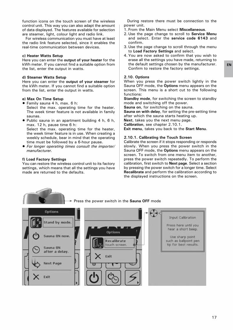
2.10. OptionsWhen you press the power switch lightly in the Sauna OFF mode, the Options menu appears on the screen. This menu is a short cut to the following functions:Standby mode, for switching the screen to standby mode and switching off the power. Sauna on, for switching on the sauna.Sauna on with delay, for setting the pre-setting time after which the sauna starts heating up.Next, takes you the next menu page.Calibration, see chapter 2.�0.�.Exit menu, takes you back to the Start Menu.
2.10.1. Calibrating the Touch ScreenCalibrate the screen if it stops responding or responds slowly. When you press the power switch in the Sauna OFF mode, the Options menu appears on the screen. To switch from one menu item to another, press the power switch repeatedly. To perform the calibration, first switch to Next page. Select a section by pressing the power switch for a longer time. Select Recalibrate and perform the calibration according to the displayed instructions on the screen.

�8
EN
Figure 2. Wall mounting of the recharge stand.
3. INSTRUCTIONS FOR INSTALLATION
The electrical connections of the control unit may only be made by an authorised, professional electrician and in accordance with the current regulations. When the installation of the control unit is complete, the person in charge of the installation shall pass on to the user the instructions for installation and use that come with the unit and shall give the user the necessary training to use the heater and the control unit!
For an overall view of the Harvia Fenix control unit see Figure �.
3.1. Installing the Wireless Control UnitThe Fenix wireless control unit comes with a table recharge stand that can be attached to a table with a screw. The recharge stand can also be wall mounted using a separate wall-mounting plate. When installing the recharge stand, observe the distance to the nearest socket: the cord measures approximately �,5 m in length. The wall-mounting plate is fixed to the wall with three screws, and the recharge stand is fastened to the plate with two screws. The recharge stand is installed outside the sauna room, in a dry place with an ambient temperature of >0 ºC. The wireless control unit can, if necessary, be attached to the charger with a screw. See Figure 2.
Check the operating range of the radio link (up to 10 m from the power unit) when installing the recharge stand. The range varies according to the structural obstacles.
The wireless control unit can, alternatively, be connected to the power unit with a cable. The required operating voltage is then supplied from the power unit through the cable and batteries can not be used. If connected to the power unit with a cable, the wireless control unit can be fixed to a wall using a special rear cover designed for wall mounting (see Figure 3). In this case you do not need a recharge stand.
When you first switch on the wireless control unit, it will automatically prompt you to calibrate the touch screen. The screen will guide you through the calibration process. After this you are asked to choose the desired panel language and set the day and time. Make the required settings and confirm. If the unit does not follow the above steps automatically, they can be carried out manually (see Quick Guide).
Before the wireless control unit is taken into use, the installer shall enable the installed features through the Service Menu.
To add or remove function icons on the screen:
�. Go to the Main Menu. 2. Use the page change to scroll through to Miscellaneous and select.3. Scroll to Service Menu and enter the service code 6�43. Confirm by pressing Confirm/Next.4. Choose Installed/Enabled Features. Here you can activate the required features, which are then displayed as function icons on the touch screen of the wireless control unit. 5. Confirm the settings.6. Select the desired function for the auxiliary output and Confirm.

�9
EN
Figure 3. Wall mounting of the wireless control unit by means of a special wall-mounting cover.
1
2
Figure 4. Opening the power unit cover and mounting the unit to a wall.

20
EN
Heater output kW
Fuse (A) Supply cable
Connection cable 400V 3N~
0-6 kW 3 x �0 5 x �,5 5 x �,5
<6-�� kW 3 x �6 5 x 2,5 5 x �,5
<��-�5 kW 3 x 25 5 x 6,0 5 x 2,5
Figure 5. Wall mounting of the power unit.
Table 1.
Heater model
Output (kW)
Fuse (A)
Supply cable
Connection cable 400V 3N~
KV50SE 5,0 3 x �0 5 x �,5 7 x �,5
KV60SE 6,0 3 x �0 5 x �,5 7 x �,5
KV80SE 8,0 3 x �6 5 x 2,5 7 x 2,5
KV90SE 9,0 3 x �6 5 x 2,5 7 x 2,5
T7C 7,0 3 x �6 5 x 2,5 7 x 2,5
T9C 9,0 3 x �6 5 x 2,5 7 x 2,5
K��GS �0,3 3 x �6 5 x 2,5 5 x �,5 +4 x �,5*
K�3,5GS �3,5 3 x 20 5 x 6,0 5 x 2,5 +4 x �,5*
K�5GS �5,5 3 x 25 5 x 6,0 5 x 2,5 +4 x �,5*
Table 2.
*) For further instructions see the instructions for installation and use for Club Combi
3.2. Installing the Power UnitThe power unit of the Harvia Fenix control unit and the power unit for colour light, if installed, are placed outside the sauna room, in a dry place with an ambient temperature of >0 ºC. The power units can be fixed to a wall. See Figure 4 for instructions on how to open the power unit cover and how to fix the unit to the wall.
Note! The power units must not be embedded into the wall, since this may cause excessive heating of the internal components of the unit and lead to damage. See Figure 5.
3.2.1. Electrical Connections of Power Unit SACF150 for HeaterPower unit SACF�50 is designed for controlling electric heaters with an output of max. �5 kW.
This power unit can also be used for controlling the lighting (max. �00 W) in the sauna room and, through the auxiliary output (max. �00 W), the ‘sauna ready’ indicator light, ventilation fan or electric heating of the building. For instructions on
how to select the desired AUX output function see chapter 2.9.9. a).
The temperature sensor in the sauna room must be connected to the SACF�50 power unit. You can also install a humidity sensor, available as an accessory, for measuring the humidity level in the sauna. For instructions on how to install the sensors see chapter 3.2.5.
The electrical connections of the power unit are made according to Figure 6. For wireless communication, the power unit must be paired up with the wireless control unit after installation (see chapter 2.9.4).
Table � shows the cable thickness and fuse size, depending on the heater output, to be used with the Fenix SACF�50 power unit. For more detailed installation instructions see the instructions for installation and use for the selected heater model.
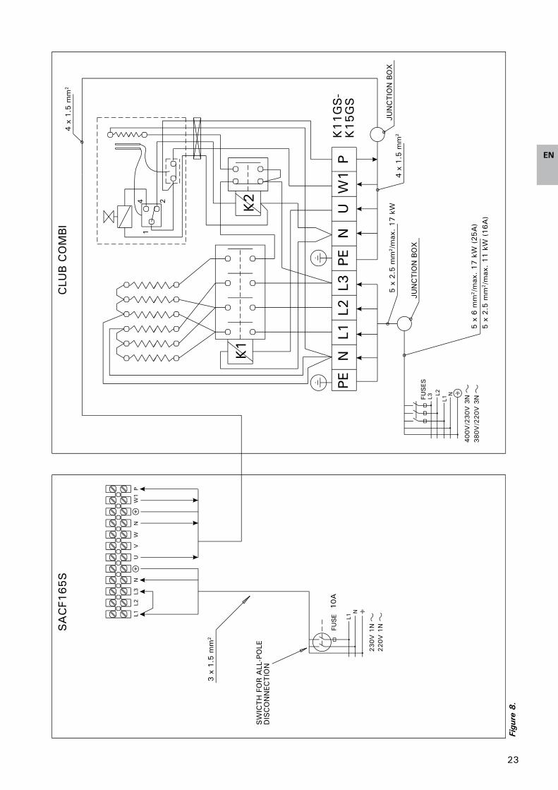
3.2.2. Electrical Connections of Power Unit SACF165S for Steamer/HeaterPower unit SACF�65S is designed for controlling heaters of max. �5 kW, steamers of max. 5 kW, and Combi combined heaters/steamers of max. �6,5 kW.
This power unit can also be used for controlling the lighting (max. �00 W) in the sauna room and, through the AUX output (max. �00 W), the ‘sauna ready’ indicator light, ventilation fan or electric heating of the building. For instructions on how to select the desired AUX output function see chapter 2.9.9. a).
The temperature and humidity sensors in the sauna room must be connected to the SACF�65S power unit. For instructions on how to install the sensors see chapter 3.2.5.
The electrical connections of the power unit are made according to Figure 7–9, depending on the heater model. For wireless communication, the power unit must be paired up with the wireless control unit after installation (see chapter 2.9.4).
Table 2 shows the cable thickness and fuse size, depending on the heater model, to be used with the Fenix SACF�65S power unit. For more detailed installation instructions see the instructions for installation and use for the selected heater/steamer model.
3.2.3. Electrical Installations of Power Unit SACF100 for Colour LightPower unit SACF�00 is designed to be used for controlling two Harvia Colour Lights with bulbs of max. 50 W / �2 V DC. The electrical connections are made according to Figure �0.
The colour light unit is connected to power unit SACF�50 or SACF�65S via the included cable measuring approximately �,5 m in length. The Harvia Colour Light also comes with a cable (T �80 °C) for connection to power unit SACF�00.
The SACF�00 unit is supplied with power (230 V �N~) via an installation cable of 3 x �,5 mm².
To be able to use the power unit SACF�00 for colour light, the colour light feature of the wireless control unit must be activated (see Chapter 2.5.�.), and for wireless communication, the colour light unit must be paired up with the wireless control unit (see Chapter 2.9.4).

2�
EN
Figu
re 6
. El
ectr
ical
con
nect
ions
of
pow
er u
nit
SA
CF1
50 f
or h
eate
r

22
EN
Figu
re 7
. El
ectr
ical
con
nect
ions
of
pow
er u
nit
SA
CF1
65S f
or s
team
er/h
eate
r (C
ombi
hea
ters
)
23
EN
Figu
re 8
.

24
EN
Figure 9. Electrical connections of power unit SACF165S (heater and SS20/SS20A steamer)

25
EN
Figu
re 1
0.
Elec
tric
al c
onne
ctio
ns o
f po
wer
uni
t SA
CF1
00 f
or c
olou
r lig
ht

26
EN
Figure 11. Installing the radio antenna of the Fenix control unit
3.2.4. Installing the Radio AntennaFor wireless communication, the radio antenna must be connected to the SACF�50 or SACF�65S power unit. The antenna is attached near to the power unit (see Figure ��) using two-sided tape.
3.2.5. Installing the Temperature and Humidity SensorsWall-mounted heaters and Combi heaters (see Figure �2).
The temperature sensor is wall-mounted above the heater, along the vertical centre line running parallel to the sides of the heater, at a distance of �00 mm from the ceiling.
Floor-mounted heaters and Combi heaters (see Figure �3).
Alternative �:The temperature sensor is wall-mounted above the heater, along the vertical centre line running parallel to the sides of the heater, at a distance of �00 mm from the ceiling.
Alternative 2:The temperature sensor is mounted to the ceiling above the heater, at a distance of 200 mm from the vertical centre line of the heater’s side.
For installing the temperature sensor near vents see the instructions in Figure �4.
With a separate steamer (SS20/A), observe that the temperature sensor must not be installed in the area affected by steam (see Figure �3).
The humidity sensor is wall-mounted as far from the heater as possible and at a distance of 500–700 mm from the ceiling.

27
EN
Figure 12. Installing the temperature and humidity sensors of the Fenix control unit, wall- mounted heaters
3.2.6. Resetting the Overheat ProtectorThe components in the sensor box control the operation of the control unit. The sensor box contains a temperature sensor and an overheat protector. An
NTC thermistor senses the temperature, and the resettable overheat protector cuts off the heater power in the case of malfunction, after which the protector can be easily reset. The reset button of the overheat protector is shown in Figure �5.

28
EN
Figure 13. Installing the temperature and humidity sensors of the Fenix control unit, floor-mounted heaters
Figure 15. Reset button of the overheat protector
Figure 14. Installing the temperature sensor near to a vent
Harvia OyPL 12
40951 MuurameFINLAND
www.harvia.fi

Harvia OyPL 12
40951 MuurameFINLAND
www.harvia.fi