2008:011 civ master's thesis
TRANSCRIPT

2008:011 CIV
M A S T E R ' S T H E S I S
Weight Reduction of a Unison Ring- A study of Composite Materials and its Potential in
Design of Future Variable Bleed Valve systems -
Simon Samskog
Luleå University of Technology
MSc Programmes in Engineering Mechanical Engineering
Department of Applied Physics and Mechanical EngineeringDivision of Solid Mechanics
2008:011 CIV - ISSN: 1402-1617 - ISRN: LTU-EX--08/011--SE

Weight Reduction of a Unison Ring - A study of Composite Materials and its Potential in
Design of Future Variable Bleed Valve systems -
Luleå University of Technology
MSc Programme in Mechanical Engineering Department of Applied Physics and Mechanical Engineering
Division of Solid Mechanics


Preface This Master Thesis was accomplished during 20th August 2007 to 18th of January 2008 at Volvo Aero Corporation. The Master Thesis is the final stage in the MSc programme in Mechanical Engineering at Luleå University of technology (LTU) and is collaboration between Volvo Aero Corporation and Luleå University of Technology. This thesis has been produced by Simon Samskog, engineering student at LTU together with Nicklas Holmberg (supervisor from VAC), the examiner has been Mats Oldenburg (Professor at the Division of Solid Mechanics, LTU). I would like to thank the people who has made the project possible and sharing their valuable experience and knowledge. Most of all I would like to thank Nicklas Holmberg who made this possible, David Bogle for all of his support regarding his understanding for the Variable Bleed Valve system (VBV-system) concepts ideas and design solutions, Hans Johansson for the big support and help with my FEM analysis and Nicklas Jansson for your help and support, regarding composite materials. Finally I would like to thank the people at VAC mainly at TL3 and TL4, for their support and patience. Thank you!
Simon Samskog, Trollhättan, January 2008


Abstract
This Master Thesis was accomplished during the period 20th August 2007 to 18th of January 2008 at Volvo Aero Corporation. The Master Thesis was the final moment in the MSc programme in Mechanical Engineering at Luleå University of Technology. During the development of a new aero engine family a new Variable Bleed Valve system (VBV-system) was designed, the second phase of this design was to reduce the weight of the components by considering alternative materials and methods of manufacture; thus improving Specific Fuel Consumption (SFC). Several concepts were discussed with regards to the VBV- system and one of these was to replace some of the existing metallic (Aluminum & Titanium) components with a composite alternative and the unison ring was considered to be a prime candidate for this study. The challenge in using composites is the complexity of the material. Different mechanical properties and performance can be achieved by different numbers of layers, fiber orientations and choice of fiber and matrix. In order to use composites, a full understanding of the mechanical behavior of the unison ring is required. This resulted in a review study of the existing unison ring. The most important task was to investigate how changes in the unison ring stiffness could affect the opening and closing of the 10 VBV doors, located in the Fan Hub Frame. With the results given in the review study, a concept generation (including basic laminate theory) was made to determine the final concept design. From the concept generation, it was determined that the unison ring should be designed as a sandwich, with composite laminates on top and bottom. Between the two composite laminates foam or honeycomb should be used. The composite material was chosen to be a standard aerospace composite, which are based on long fiber reinforcements (carbon) with epoxy matrix. Most of the fibers are orientated along the unison ring, to keep both tensile stiffness (AE) and bending stiffness along the unison ring as high as possible. To ensure that the composite laminate was fiber dominated, at least 10% of the fibers and a maximum of 60% of the fibers were oriented in four different directions. The research performed in this study has been a limited concept study, therefore more studies are needed before a final design can be achieved.


Abbreviations/Nomenclature DSE Design Space Exploration FEM Finite Element Method FEA Finite Element Analysis LTU Luleå University of Technology VAC Volvo Aero Corporation LPC Low Pressure Compressor HPC High Pressure Compressor HPT High Pressure Turbine LPT Low Pressure Turbine FHF Fan Hub Frame VBV Variable Bleed Valve Diff_scalar The maximum rotational difference between two doors UD Uni-directional NOP Normal operation load
fV Volume fraction fiber
fρ Fiber density
mρ Matrix density
fE Young’s modulus for fibers
mE Young’s modulus for matrix
cE Young’s modulus for composite
cσ Tensile strength composite
mσ Tensile strength matrix
1E Axial stiffness of a composite
2E Transverse stiffness for a composite
ijυ Poisson’s ratio (contraction in j-direction with applied stress in i-direction)
11A Reduced stiffness tensor, assuming orthotropic symmetry
11A Reduced, transformed stiffness tensor (assume orthotropic symmetry)
fw Weight of fiber
mw Weight of matrix
mW Weight fraction


Table of Contents 1. INTRODUCTION ...........................................................................................................................- 1 -
1.1. MAKE IT LIGHT ......................................................................................................................... - 1 - 1.2. VOLVO AERO CORPORATION..................................................................................................... - 1 - 1.3. BACKGROUND OF THE THESIS.................................................................................................... - 2 - 1.4. PROBLEM STATEMENT ............................................................................................................... - 2 - 1.5. PURPOSE .................................................................................................................................... - 2 - 1.6. GOALS ....................................................................................................................................... - 3 -
1.6.1. Main goals........................................................................................................................- 3 - 1.6.2. Part goals .........................................................................................................................- 3 -
1.7. LIMITATIONS ............................................................................................................................. - 3 - 2. THEORY..........................................................................................................................................- 4 -
2.1. THE VBV-SYSTEM..................................................................................................................... - 4 - 2.2. MAIN PARTS IN VBV SYSTEM.................................................................................................... - 5 -
2.2.1. Unison ring.......................................................................................................................- 5 - 2.3. STALL ........................................................................................................................................ - 6 - 2.4. COMPOSITES .............................................................................................................................. - 7 -
2.4.1. Introduction to Composites ..............................................................................................- 7 - 2.4.2. Basics about Composites..................................................................................................- 7 - 2.4.3. The Fiber..........................................................................................................................- 7 - 2.4.4. Matrix...............................................................................................................................- 8 - 2.4.5. Characteristics .................................................................................................................- 8 - 2.4.6. Design of Composite materials ........................................................................................- 9 - 2.4.7. Choice of Composite ......................................................................................................- 10 - 2.4.8. Manufacturing of Composites ........................................................................................- 10 - 2.4.9. Axial stiffness .................................................................................................................- 11 - 2.4.10. Transverse stiffness ........................................................................................................- 11 - Shear stiffness ..................................................................................................................................- 12 - 2.4.11. Poisson’s ratio ...............................................................................................................- 13 - 2.4.12. Composite lay-up and Off-axis fiber orientation............................................................- 13 -
3. METHOD.......................................................................................................................................- 18 - 3.1. FIND THE DESIGN CRITERIA’S................................................................................................... - 18 -
3.1.1. Discover the needs .........................................................................................................- 18 - 3.2. FEM ANALYSIS (PRE-STUDY) .................................................................................................. - 18 -
3.2.1. Introduction to FEM model............................................................................................- 19 - 3.2.2. Contact setup..................................................................................................................- 20 - 3.2.3. Loads..............................................................................................................................- 22 - 3.2.4. Boundary conditions ......................................................................................................- 24 - 3.2.5. Material..........................................................................................................................- 25 - 3.2.6. Rotational difference between two doors .......................................................................- 25 - 3.2.7. Contact forces ................................................................................................................- 25 -
3.3. SENSITIVE STUDY (GRADIENT SOLUTION) ................................................................................ - 25 - 3.4. RESULTS (PRE-STUDY) ............................................................................................................. - 26 - 3.5. RESULT GRADIENT SOLUTION .................................................................................................. - 28 - 3.6. CONCLUSIONS.......................................................................................................................... - 31 - 3.7. SUMMARY ............................................................................................................................... - 31 -
3.7.1. Stiffness requirements ....................................................................................................- 31 - 3.7.2. Design criteria for unison ring: .....................................................................................- 32 -
3.8. CONCEPT GENERATION ............................................................................................................ - 32 - 3.8.1. Choice of cross-section .................................................................................................. - 32 -
3.9. BOLTS, JOINTS BUSHINGS, ETC ................................................................................................. - 33 -

3.10. NUMBER OF LAYERS AND FIBER ORIENTATION ........................................................................ - 34 -
3.10.1. Axial stiffness according to fiber orientation ................................................................. - 35 - 3.10.2. Global stiffness in the laminate ......................................................................................- 35 -
4. RESULTS.......................................................................................................................................- 36 - 4.1. RESULT CONCEPT GENERATION............................................................................................... - 36 -
4.1.1. Sandwich concept, Type 1 ..............................................................................................- 36 - 4.1.2. Door and Actuator block................................................................................................- 39 - 4.1.3. Bellcrank bolt and retaining ring...................................................................................- 40 - 4.1.4. Blind bolt (Huck fasteners)............................................................................................. - 41 - 4.1.5. Sandwich concept (Type 2)............................................................................................. - 42 - 4.1.6. Aluminum blocks (Type 2)..............................................................................................- 43 -
5. CALCULATIONS .........................................................................................................................- 44 - 5.1. MATERIAL DATA...................................................................................................................... - 44 - 5.2. BOLT BENDING/SHEAR ............................................................................................................. - 44 -
5.2.1. Bellcrank bolt in type 1 ..................................................................................................- 44 - 5.2.2. Bellcrank bolt, type 2 ..................................................................................................... - 45 - 5.2.3. Blind bolts (Huck fasteners) in type 1 ............................................................................- 45 -
5.3. CONTACT PRESSURE (BEARING STRENGTH)............................................................................. - 46 - 5.4. RESULT FEM ANALYSIS .......................................................................................................... - 46 -
5.4.1. Unison ring.....................................................................................................................- 46 - 5.4.2. Aluminum block FEM analysis.......................................................................................- 48 -
6. MANUFACTURING.....................................................................................................................- 50 - 7. COSTS ............................................................................................................................................- 50 - 8. WEIGHT REDUCTION...............................................................................................................- 51 - 9. DISCUSSION.................................................................................................................................- 52 -
9.1. CONCEPT EVALUATION MATRIX............................................................................................... - 54 - 10. CONCLUSIONS........................................................................................................................- 55 - 11. PROPOSAL FOR FURTHER WORK ...................................................................................- 55 - REFERENCES .......................................................................................................................................- 56 - APPENDIX .............................................................................................................................................- 59 -

- 1 -
1. Introduction This chapter will describe the background of this research and synopsis on Volvo Aero Corporation .
1.1. Make It Light This chapter will in brief explain the mission statement and essence for Volvo Aero The lighter the aircraft engine is, the less fuel it consumes for any given flight, that is why Volvo Aero focus on developing lightweight solutions for aircraft engine structures and rotors, including a range of technologies developed through Swedish national programs and EU funded programs. Make It Light expresses the essence of Volvo Aero’s mission, and represents the contribution to the Advisory Council of Aeronautics Research in Europe (ACARE) target of 50% less carbon dioxide ( 2CO ) from air transport by the year 2020, in comparison with the technology level of the year 2000. Volvo Aero’s combination of optimized fabrication, metal deposition and shorter ducts can produce metallic engine structures, such as intercases and turbine structures that are as much as 20% lighter. (volvoaero.com, 2007)
1.2. Volvo Aero Corporation This chapter will in make a short introduction to Volvo Aero Volvo Aero develops and manufacture high-technology components for aircraft, space propulsion and aero engines, in cooperation with the world’s leading engine manufacturers.
Volvo Aero also offer extensive aviation services that help their partners to increase profitability and focus on their core business – including leasing, logistics, asset management, inventory sales, distribution and redistribution, as well as overhaul and repair of aircraft engines and industrial gas turbines. (volvoaero.com, 2007)
In brief Volvo Aero (volvoaero.com, 2007):
• Have components in more than 80% of the world’s large aircraft. • Are one of the world’s largest suppliers of commercial space propulsion combustion
chambers and nozzles. • Supply material to all the major airlines. • Have approx. 3.500 employees. • Have a turnover of 8,048 million SEK (Year 2006).

- 2 -
1.3. Background of the Thesis This chapter will explain the background of this thesis As a result of the increasing demands and requirements of less fuel usage in flight industry, and reduced 2CO emissions the aircrafts and engine manufacturers have to reduce the weight of their components. Today both the aircraft and jet engine manufacturers utilize light materials (Titanium, Aluminum, etc), but since Titanium, which is a popular material has become very expensive, Aero engine manufacturers are looking at new alternative lightweight materials.
1.4. Problem statement This chapter will describe the main task of this Master thesis and the problem statement During the development of a new aero engine a completely new design of the Variable Bleed Valve system (VBV system) was made, see figure 2. But since the engine in total was a little bit too heavy according to the required weight, the engines weight had to be reduced. A couple of concept solutions were discussed and the outcome of that was to see if it was possible to replace some metal components in the VBV system with composite materials instead. One of the suggested components to replace material was the “unison ring”. Due to Volvo Aero’s and aero engine manufacturer’s limited experience and the recent advancements in composite materials, a research into the use of composites and the possibility of its usage on the unison ring was required. These were the main issues that needed to be addressed:
• Is it possible to use composite materials in the unison ring ? • What are the existing design criteria? • Is it possible to manufacture the geometry required using composite materials? • Could a weight reduction be achieved with the use of composites? • What would be the cost to weight ratio benefits of using a composite material?
1.5. Purpose
The purposes with this master thesis is to investigate the possibility to weight reduce the unison ring by designing it in composite material, investigate the important factors from the existing design that would have large influence on the composite design and the required material properties.

- 3 -
1.6. Goals This chapter will explain the goals in this master thesis
1.6.1. Main goals
• Investigate the possibility of replacing existing aluminum design of unison ring with composite material to reduce weight.
• Identify and conclude the important factors when designing in composite materials
1.6.2. Part goals
• Multiple concept studies. • Make sure that the concepts/ideas are realizable • The concepts/ideas should be well documented
1.7. Limitations This chapter will describe the limitations in this thesis. This master thesis will cover the different requirements that are needed if composites are to be introduced. Discussions and conclusions on important design parameters for the unison ring will also be covered. The VBV-system is based on several components, but this thesis will not cover these parts, the unison ring is the only component in the VBV-system that’s being investigated. Basic laminate theory will be used in order to give a good understanding for the composite and its material as well its mechanical properties. No deeper studies according to laminate theory will be discussed. A few concepts will be discussed but no further studies into detail design and final designs will be attempted. The main focus will be:
• Come up with a few concepts and explain them • Evaluate these concept according to manufacturing and stress analysis • Explain and investigate the possibility to use composite material. • Investigate if the concept/ideas are realizable • Investigate if the unison ring can be reduced in weight with composites • Investigate and explain the strengths and the weaknesses in each concept/idea • Estimate costs etc • Documenting results and conclusions for future studies.

- 4 -
2. Theory This chapter will describe the VBV System’s main function, the phenomenon called stall will also be explained. This chapter will also give a basic theory introduction to composite material, for those who find it unnecessary can skip this part. However it is advised that the reader go through the whole chapter 2. Volvo Aero develops and manufactures a component called Fan Hub Frame (FHF), see figure 1. The FHF is situated between the Low Pressure Compressor (LPC) and High Pressure Compressor (HPC), see figure 2, and it is on FHF the VBV system is mounted (The VBV-system is showed figure 3).
Figure 1. Delivery of the first FHF (source: Volvo Aero, 2007)
2.1. The VBV-system This chapter will give an introduction to the VBV-system During the operation of an aero engine, a condition known as a "surge" may occur, an engine surge is generally regarded as a mismatch between the speed of the compressor blades and the incoming air. An engine surge is typically a precursor to an engine stall event. Engine surges are characterized by a sudden and large loss of power, a loss of air flow, an increase in temperature and mechanical vibration. These mechanical vibrations, as well as the temperature increases, enforce substantial stress on the engine and mostly on the turbine blades. While also occurring under other operating conditions, an engine surge event will most often occur during acceleration

- 5 -
Figure 3. The VBV-system used today (Source: Volvo Aero)
Figure 2. Two-shaft compressor (Source: Volvo Aero, 2007)
To avoid this condition a system called the VBV (Variable Bleed Valve) was developed, the VBV systems main function is to balance the air from the compressor and pass the excess out through into the pass air and through that decrease the pressure difference between the LPC and HPC [8]. Figure 2 shows were the VBV system is placed.
2.2. Main parts in VBV system This chapter will in brief explain the main part in the VBV system The VBV system is based on ten doors located circumferentially around the intermediate frame (FHF). The doors are the ones that opens inside the compressor room and lead out the air. From the doors there is a linkage system which controls the movement of the doors. These linkages are finally attached to a big ring, also called the unison ring. On this ring are the two actuators attached which by pulling or pushing rotates the unison ring to open or close the doors. Figure 3 shows how the VBV system looks like today. In this master thesis there will be no further explanations about the doors the linkage etc, since the main focus in this report is the unison ring.’
2.2.1. Unison ring This chapter will explain in more detail what the unison ring does. As mentioned above the unison ring rotates as the actuators are pulling and pushing back and forward in a translational movement. In detail what’s happen is that when the actuators translate they make the actuator bellcrank to rotate which then rotates the ring. Since there are door bellcranks mounted in the unison ring, these will also rotate as long as the ring rotates, making the doors then to open and close.
Location of the unison ring and the FHF and VBV-system

- 6 -
2.3. Stall This chapter will explain what stall/surge is which is important to understand since it is one of the backgrounds for the VBV-system. Compressor stall is a situation of irregular airflow through the compressor stage of a jet engine, causing a stall of the vanes of the compressor rotor . All kinds of compressor stalls result in loss of engine power, this power loss may only be momentary (occurring very quickly), or may cause the whole engine to shut down. Another word for compressor stall when it affects the airflow through the entire engine is also known as compressor surge (important to notice is that the definition differs, and often they are used exchangeable). In general are there two types of compressor stall.
• The first is the "axis-symmetric stall", which is a straightforward expulsion of air out the intake due to the compressor's failure to maintain pressure on the combustion chamber [10].
• The second is "rotational stall", which is the cause of air flow disturbance causing
standing pockets of air to rotate within the compressor without moving along the axis. Without new air from the intake passing over the stalled compressor vanes they overheat, causing accelerated engine wear and possible damage [9].
Compressor stalls could be compared to aerodynamic stall which is the cause of an airfoil failing its lifting capability. This results in a sudden change in the pressure differential between the intake and the combustion chamber. Therefore must the pilot take this into account when dropping airspeed or increasing throttle. There are four factors that can stimulate the compressor to stall [10]:
• Engine thrust too high for the operating altitude • Engine operation outside specified design parameters • Turbulent or disrupted airflow to the engine intake • Contaminated or damaged engine components (such as damaged or wrongly positioned
guide vanes) • Abrupt increases in engine thrust
If an entire stage of airfoils stalls an increase in rotor speed may occur due to the large reduction in work done by the stalled rotor stage. This can results in a domino effect in which the remainder of the compressor stages starts to stall, resulting that the compressor loses its capability to maintain a pressure ratio, which can cause backflow from the combustor section. When a single airfoil stalls pocket of inert air occurs, this inert air passes to the next airfoil on the rotor, causing the stall to propagate. Compressor stalls can cause a compressor surge which is known as loud bangs emanating from the engine. During a compressor surge the pressure at the compressor stages is lower than at the combustion chamber which causes a bad pressure gradient. This causes a back flow of air through the compressor. To avoid this phenomenon different solution has been developed, one is to put a number of compressor stages running on multiple spools and thus varying speeds to fight this problem (three shafts). Other solutions are variable stator vanes and doors opening inward to the compressor and letting air out [9].

- 7 -
2.4. Composites This chapter will give an introduction to composite materials and explain some basic composite theory.
2.4.1. Introduction to Composites The knowledge of composite material is more or less established today, its benefits are well documented and the varieties of applications for which composites are used, ranging from "industrial, sports to high performance aerospace components. As mentioned earlier have weight issues in the flight industry have become more and more important, the research for lighter design and new manufacturing methods has rapidly increased. The technology has come very far and now days most of the parts in airplanes are build with composites, (wings, plane body, fan blades, etc) one example is Boeings 787 Dreamliner which most of its exterior are built in composites.
2.4.2. Basics about Composites A composite usually refers to a “matrix" material that is reinforced with fibers, in its most basic form is the composite material based on two elements, bulk material (the ‘matrix’) and reinforcement (fiber), the fiber is added primarily to increase the strength and stiffness of the matrix. Together they produce a material with properties that are and much better than the properties of these elements on their own. The most common made composites can be divided into three groups, Polymer Matrix Composites, Metal Matrix Composites and Ceramic Matrix Composites, but in this thesis will only polymer composites be discussed.
2.4.3. The Fiber It has already been mentioned that the fiber is the one that give the composite its strength and stiffness, it is the fiber that take most of the applied load. How much of the applied load in the composite the fiber will carry are depending both on the volume fraction ( fV ) of fiber and on the stiffness of the two including components (fiber, matrix). The fibers can be made of different material such as, glass, carbon or aramid. Figure 4.1 and figure 4.2 below show how tensile modulus and cost ratio between different fiber types [11].
Figure 4.1. Tensile modulus for different fibers Figure 4.2. Cost ratio between different fibers (Source: hexcel.com [11], 2007) (Source: hexcel.com [11], 2007) Many composite properties are directly dependent on the fibers distribution and orientation (the architecture of the fibers). This includes the diameter of the fiber, the length of the fiber, volume
Tensile Modulus Cost ratio

- 8 -
fraction of fiber, their alignment and packing arrangement. Many calculations regarding composites are based on the volume fraction of the included components (matrix, fiber). Equation (1) shows how the expression for volume fraction of fiber [1].
densitymatrix
densityfibermatrixfractionweightwfiberfractionweightw
www
V
m
f
m
f
mmff
mff
=
==
=
+=
ρ
ρ
ρρρ
(1)
2.4.4. Matrix The role of the matrix is to support the fibers and bond them together in the composite material. It transfers any applied loads to the fibers, keeps the fibers in their position and chosen orientation. The matrix also gives the composite environmental resistance and determines the maximum service temperature of a composite. When selecting a composite is the maximum service temperature one of the key selection criteria for choosing the best suitable composite matrix. The cure process for a matrix can easiest be represented by pre-polymers whose reactive sites join together forming chains and cross linking. In practice, there are more constituents and the cure process is more complex. There are three main types of matrices Epoxy, Phenolic and Bismalemide (and polyimide) [11]
2.4.5. Characteristics The simplest lay-up for a composite is the unidirectional composites (UD), which is a composite with only fibers in one direction (see figure 5.1), the UD composite have predominant mechanical properties in one direction and are said to be orthropic (different properties in different directions). Components made from fiber-reinforced composites can be designed so that the fiber orientation produces optimum mechanical properties in certain directions. Figure 5.1 and figure 5.2 shows a UD lay-up and a fabric lay-up.
Figure 5.1. Unidirectional composite Figure 5.2. Fabric composite (Source: hexcel.com [11], 2007) (Source: hexcel.com [11], 2007)

- 9 -
W
d e
σ
σ
Figure 7. Design parameter
Figure 5.2 shows a fabric composite, in this case a composite with fibers orthogonal to each other. Caution the word fabric means the compound of fibers, it can be both UD and weaved fibers. As explained previously the fiber direction can be arranged so it meets specific mechanical performances of the composite. Figure 6.1 below shows a Quasi-isotropic lay-up and figure 6.2 shows a unidirectional lay-up.
Figure 6.1. Quasi-isotropic lay-up Figure 6.2. Unidirectional lay-up (Source: hexcel.com [11], 2007) (Source: hexcel.com [11], 2007) To describe the lay-up of a UD composite laminate a convention is used, the convention for the quasi-isotropic lay up is [ ]0/90/45/45/45/90/0 2 +−+ the subscript 2 indicates that there are two plies in the laminate. The convention can also be written as [ ]s45/45/90/0 −+ or more simplified as [ ]s45/90/0 ± the subscript s indicates that the laminate is symmetric about the mid plane.
2.4.6. Design of Composite materials Due to the brittleness and progression damage before failure of bolted joints, is it difficult to analytically predict failure. Instead are design rules used to avoid shear out and net section failure. From the , PSS-03-203 Structural Materials Handbook Vol. 1 Polymer Composites [15] can different design criteria’s regarding bolted and riveted joints be found, a few of them are mentioned below. To ensure that the laminate will be fiber dominant (fiber breaks first), must the lay-up include at least 10 % and maximum of 60% fiber in all direction, in at least 4 fiber angles. Another design criteria is to assume that the tightening torque or pre-tension of a bolt are not possible, this due to the fact that the clamped composite will relax over time and the strength will be lost [15]. Due to the low interlaminar strength of the composite the use of interference fit fasteners are restricted to a accurate clearance fit. With the risk of damaging the hole when fasteners are mounted, and to the risk of delamination, the tolerance for a hole is set as [ ]mmmm 100,0000,0 +−
For single hole it has been found that a minimum of 4=dW

- 10 -
and a minimum of 3>de
are required to be sure that the composite will achieve full bearing
strength [15]. Important to notice is that these criteria’s can be eluded, but caution must be taken since it will affect the bearing strength of the bolted or riveted joint (see figure 7). One problem that has been discovered with aluminum and carbon fiber composites is galvanic corrosion, therefore should they not be in direct contact with each other, aluminum bolts/rivets should therefore be avoided [15].
2.4.7. Choice of Composite For this thesis is the Composite material used assumed to be a standard aerospace composites, which is a variant of an advanced composite (long fiber composites with a high volume fraction of fiber, ~60% fiber), but with carbon fiber reinforcement and a epoxy matrix. The material data of the composite can be seen below, the data used is from MIL-HDBK-17-3F, se reference [23].The compressive design strain was chosen to be 0,3%, which correspond to a typical value for a damaged laminate [23].
• Density matrix ( mρ ): ~1300 3/ mkg
• Density fiber ( fρ ): ~1800 3/ mkg
• Volume fraction fiber ( fV ): ~0,63%
• Density ( cρ ): ~1615 3/ mkg
• Poisson ratio tv12 : 0,28 • Compressive design strain: 0,3% • Assumed tensile modulus fE : 250 GPa (1-direction)
• Assumed tensile modulus mE : 3 GPa (1-direction)
2.4.8. Manufacturing of Composites To manufacture a Composite structure, different methods can be used depending on the ingredients (thermoplastic polymer, chopped fibers, thermoset polymer etc) and final geometry of the design. For this thesis there will be three methods discussed (due to the choice of aerospace composite), pre-preg, filament winding and resin injection, [1]. Pre-preg is the standard and most widely used composite, it consists of a tape or sheet of fibers pre-impregnated with semi-cured resin. To manufacture a pre-preg, fibers and resin are placed between sheets of siliconised paper or plastic film, which then are rolled or pressed to make sure strength and that the fibers are wet out. The last step is to cure the fiber/resin compound to create a flexible accumulation [1]. The filament winding process is based on fiber towels or fiber bundles being drawn through a bath of resin and then wound onto a mandrel or former of required shape. Resin injection is basically made that dry fibers are placed in a mould, which resin are injected into, the cure occurs within the mould.

- 11 -
2.4.9. Axial stiffness The easiest model that describes the elastic behavior of aligned long fiber composites can be seen in figure 8.1. The composite is treated as if it were bonded of two parallel slabs [1] of the two included components (fiber and matrix). The thickness of the slabs is dependant on the volume fraction of the matrix and fiber. The slabs are both of the same length and with the assumption that there is no interfacial sliding, the both slabs have the same strain, ε . The subscript 1 means that the stress is applied in direction of the fiber.
Figure 8.1 Schematic illustration of a composite containing a volume fraction fV of aligned continuous fibers
Figure 8.1 shows that the axial strain in the fiber and in the matrix must correspond to the ratio between Young’s modulus for each included specimen, the axial strain can be derived as [1]:
m
mm
f
ff EE
11
111
σεσ
εε ==== (2)
The elastic modulus can be expressed as [1]:
ffmf EVEVE +−= )1(1 (3) This is a well known rule and it’s called “Rule of Mixtures” and indicates that the composite stiffness is simply just a weighted mean between the moduli of the two included specimen (matrix, fiber). This expression is very accurate with the assumption that the fiber is long enough for the equal strain assumption to apply.
2.4.10. Transverse stiffness The prediction for transverse stiffness in a composite is far more difficult than for the axial stiffness, in this thesis we will only focus on the simple treatment, since it will give a quite good approximation. For a more detailed description please read (D. Hull and T.W.Clyne, an Introduction to Composite Materials, second edition, 1996). In the same way as with the axial stiffness the composite can be treated as a slab, see figure 8.2 below.
fV−1
fV
0x01xε
m1σ
f1σ1σ 1σ
1
2 3

- 12 -
Figure 8.2. Schematic illustration of a composite containing a volume fraction fV of aligned continuous fibers In the model in figure 8.2 there will be two directions that are transverse to the fiber, 2 and 3 which are equal, in reality they have slightly different properties, due to difference in packaging. With the assumption of equal stress in the two phases (matrix and reinforcement), the stiffness expression during transverse load can be described as:
⎟⎟⎠
⎞⎜⎜⎝
⎛ −+
=
m
f
f
f
EV
EV
E)1(
12 (4)
The model is included in the rules of mixture model and the equal stress treatment is called “Reuss model”. The model is easy but unfortunately it gives only an approximation for 2E .
Shear stiffness The shear stiffness can be treated in similar way as the axial and transverse stiffness’s, again using the slab model (see figure above). To evaluate the shear stiffness in a composite a net shear is evaluated, which comes from the applied shear stress [1]. The shear modulus ijG is the ratio between shear stress ijτ and shear strain ijγ
jiij ττ = leads to the assumption
jiijjiij thatsoGG γγ == (5) Since the direction 2 and 3 are assumed equivalent in the aligned fiber composite the following expression holds 3223312112 GGGGG =≠== (6) Equal stress assumptions give the shear modulus:
2σ
2σ
f2σ
m2σ fV−1
fV
ffV2ε
)1(2 fm V−ε
1
2 3

- 13 -
⎟⎟⎠
⎞⎜⎜⎝
⎛ −+
=
m
f
f
f
GV
GV
G)1(
112 (7)
2.4.11. Poisson’s ratio The Poisson ratio 12v can be estimated using the equal strain assumption and 21v follows from stiffness symmetry considerations, see below.
1
21221
12 )1(
EEvv
vVvVv mfff
=
−+= (8)
See ref [1] for more information.
2.4.12. Composite lay-up and Off-axis fiber orientation This chapter will describe how the global stiffness and the lay-up of the composite was chosen. Elastic deformation of laminates Before going on with the theory for the elastic deformation in laminate, some statements must be said. First of all will not the theory in detail be described, this chapter will only cover the most important parts. This theory are both based on the theory written in the book “An Introduction to Composite Materials, D. Hull, T. W. Clyne, second edition, 1996 [1] In tensor form can the stress be expressed as ijσ , acting in i-direction on a plane with normal in j-
direction. The relationship between ijσ and ijε can be expressed as klijklij C εσ = , where ijklC
represent the stiffness tensor which is a four-rank tensor ( 8134 = equations). For each equation (pair of I and j), by using Einstein summation and the effect of symmetry the following matrix equation can be expressed.
ppqp C εσ = (9) This can be written as:
⎥⎥⎥⎥⎥⎥⎥
⎦
⎤
⎢⎢⎢⎢⎢⎢⎢
⎣
⎡
⎥⎥⎥⎥⎥⎥⎥
⎦
⎤
⎢⎢⎢⎢⎢⎢⎢
⎣
⎡
=
⎥⎥⎥⎥⎥⎥⎥
⎦
⎤
⎢⎢⎢⎢⎢⎢⎢
⎣
⎡
12
31
23
3
2
1
6661
51
41
31
262524232221
161514131211
12
31
23
3
2
1
γγγεεε
τττσσσ
CCCCC
CCCCCCCCCCCC
MMMM
MMMMM
MMMMM
MMMMM (10)

- 14 -
The elementary analysis of a composite laminate is the assumption that each lamina is in plane stress state so 031233 === ττσ . This assumption is a good approximation for thin laminate Eq (10) can now be written as
⎥⎥⎥
⎦
⎤
⎢⎢⎢
⎣
⎡
⎥⎥⎥
⎦
⎤
⎢⎢⎢
⎣
⎡=
⎥⎥⎥
⎦
⎤
⎢⎢⎢
⎣
⎡
12
2
1
66
2221
1211
12
2
1
0000
γεε
τσσ
CCCCC
(11)
where,
1266
2112
222
2112
121
2112
21212
2112
111
1
11
1
GCvv
EC
vvEv
vvEvC
vvEC
=−
=
−=
−=
−=
(12)
12G is the shear modulus
Equivalently the strain can be calculated from the stress by using the inverse of the stiffness tensor [C], the compliance tensor [S]= [ ] 1−C .
⎥⎥⎥
⎦
⎤
⎢⎢⎢
⎣
⎡
⎥⎥⎥
⎦
⎤
⎢⎢⎢
⎣
⎡=
⎥⎥⎥
⎦
⎤
⎢⎢⎢
⎣
⎡
12
2
1
66
2221
1211
12
2
1
0000
τσσ
γεε
SSSSS
(13)
Off-axis constants of lamina This chapter will describe the procedure when the composite has fiber directions other than along the axis, This chapter will only cover the most important. For more information please read “ An Introduction to Composite Materials”, D. Hull, T. W. Clyne, second edition, 1996 [1]. See figure 9 for a schematic illustration of lamina with off axis fiber

- 15 -
Figure 9. Schematic illustration of off-axis fiber The first thing to do is to determine the induced strains in the lamina according to the fiber axis. The stress and strain relation can then be expressed as kjlikij aa σσ = (14)
ika is the direction cosine of the (new) i-direction referring to the (old) k-direction and jla is the direction cosine of the (new) j-direction referring to the (old) l-direction. If 11σ is expressed 1σ it can be expressed with the applied stress xσ The same can be done with the other stresses, yσ , xyτ This gives us
yyxxyx aaaaaaaa σσσσσ 121211121211111111 +++= (15) If φ is the angle between fiber axis and stress axis, then [a] can be expressed as
)cos()sin()90cos(
)sin()90cos()cos(
22
21
12
11
φφφ
φφφ
=−=+=
=−==
aaaa
(16)
This will then lead to
1
φ
2
yσ
xσ
x
x

- 16 -
⎥⎥⎥
⎦
⎤
⎢⎢⎢
⎣
⎡
⎥⎥⎥
⎦
⎤
⎢⎢⎢
⎣
⎡
−−−=
⎥⎥⎥
⎦
⎤
⎢⎢⎢
⎣
⎡
xy
y
x
τσσ
φφφφφφφφφφφφφ
τσσ
)(sin)sin()cos()sin()cos()sin()cos(2)(cos)(sin
)sin()cos(2)(sin)(cos
2
22
22
12
2
1
(17)
Or written in Matrix form [ ]⎥⎥⎥
⎦
⎤
⎢⎢⎢
⎣
⎡⋅=
⎥⎥⎥
⎦
⎤
⎢⎢⎢
⎣
⎡
xy
y
x
Tτσσ
τσσ
12
2
1
(18) Equivalently can the stress relative the loading direction be expressed as.
[ ]⎥⎥⎥
⎦
⎤
⎢⎢⎢
⎣
⎡=
⎥⎥⎥
⎦
⎤
⎢⎢⎢
⎣
⎡−
12
2
11
τσσ
τσσ
T
xy
y
x
(19)
The strain can be expressed in similar way as equation (18), to work in terms of engineering strain etcxyxy ,2εγ = [ ]T must be modified (halving and doubling the elements of matrix T Equation (19) can then be expressed as
[ ]⎥⎥⎥
⎦
⎤
⎢⎢⎢
⎣
⎡
⋅=⎥⎥⎥
⎦
⎤
⎢⎢⎢
⎣
⎡
xy
y
x
Tεεε
εεε
'
12
2
1
(20)
The stress –strain relationship expressed relative the loading direction then becomes.
[ ] [ ]{ } [ ] [ ]⎥⎥⎥
⎦
⎤
⎢⎢⎢
⎣
⎡⋅⋅=
⎥⎥⎥
⎦
⎤
⎢⎢⎢
⎣
⎡
⇒= −
12
2
11
γεε
τσσ
εσ CTC
xy
y
x
(21)
With equation (20)
[ ] [ ] [ ] [ ] [ ] [ ]⎥⎥⎥
⎦
⎤
⎢⎢⎢
⎣
⎡
⋅=⎥⎥⎥
⎦
⎤
⎢⎢⎢
⎣
⎡
⋅⋅⋅=⎥⎥⎥
⎦
⎤
⎢⎢⎢
⎣
⎡⋅⋅=
⎥⎥⎥
⎦
⎤
⎢⎢⎢
⎣
⎡−−
xy
y
x
xy
y
x
xy
y
x
CTCTCTεεε
εεε
γεε
τσσ
'1
12
2
11 (22)
From “laminate shell theory” (Kirchhoff assumptions), the applied forces, moments to strain, curvature can be expressed as (see [24], [29] for more information):

- 17 -
⎭⎬⎫
⎩⎨⎧⎥⎦
⎤⎢⎣
⎡=
⎭⎬⎫
⎩⎨⎧
⎪⎪⎪⎪
⎭
⎪⎪⎪⎪
⎬
⎫
⎪⎪⎪⎪
⎩
⎪⎪⎪⎪
⎨
⎧
⎥⎥⎥⎥⎥⎥⎥
⎦
⎤
⎢⎢⎢⎢⎢⎢⎢
⎣
⎡
=
⎪⎪⎪⎪
⎭
⎪⎪⎪⎪
⎬
⎫
⎪⎪⎪⎪
⎩
⎪⎪⎪⎪
⎨
⎧
κε
χκκγεε
0
0
0
0
662616662616
262212262212
161212161211
662616662616
262212262212
161211161211
DBBA
MN
or
DDDBBBDDDBBBDDDBBBBBBAAABBBAAABBBAAA
MMMNNN
xy
y
x
xy
y
x
xy
y
x
xy
y
x
(23)
The matrices A, B and D is given as a sum of the stiffness of each layer and its distance from the mid-plane as
[ ] [ ] [ ]
[ ] [ ] [ ]
[ ] [ ] [ ]∑∫
∑∫
∑∫
=−
=−
=−
−==
−==
−==
n
kkkk
z
z
n
kkkk
z
z
n
k
t
kkk
z
z
hhCdzzCD
hhCzdzCB
hhCdzCA
top
bottom
top
bottom
atelatop
bottom
1
31
32
1
21
2
11
)(31
)(21
)(min48476
(24)
The superscript 0 means mid-plane strain, as seen in the expression above, A represent extensional stiffness in-plane, D matrix represent the bending stiffness and the B matrix is a coupling stiffness connecting the extension and bending. It can be noted that A, D elements corresponds to tE ⋅ and )12/(~ 3tE ⋅ for a homogenous material, equivalent to the extensional and bending of a beam with unit width. For more information please see [24], [29], atelat min is the thickness on one single laminate and kt is the total thickness of the laminate. By treating the laminate as a homogeneous material, an equivalent modulus in the x-direction is approximately given by:
0011xxx
kk
x EtA
tN
εε ≈⋅≈ (25)
From equation (11), (12), (22) and (25) the global stiffness in x-direction can be express as:
∑
∑
=
== n
kk
n
kkk
global
t
tCA
1
111
11
)( (26)
Where

- 18 -
)(sin)(cos)42()(sin)(cos 22
66124
224
1111 φφφφ CCCCC +++= (27)
3. Method This chapter will explain the work method I used to get to the goal
3.1. Find the design criteria’s This chapter will explain how the different needs and requirements for the unison ring were achieved.
3.1.1. Discover the needs The first thing that was done was to gather as much information as possible about today’s unison ring, the more information that could be brought out the better understanding about today’s design. The goal was to find the decisions and reason why today’s unison ring was designed as it is designed today. The information were gathered by reading technical reports written and by asking people who where involved during the development of today’s unison ring. In a material change from aluminum to composite material investigations of the needs for the unison ring had to be done. From chapter 2 it was discovered that depending on the fiber type, matrix type, and fiber orientation, the composite will have different mechanical properties, such as strength and stiffness. Due to the orthotropic properties and by orientation of the fibers the mechanical properties can be orientated. Meaning that we can control the mechanical properties in directions where it is best suited. This resulted in a huge range of possible solutions for how to design the unison ring, the solution was to study which direction of stiffness’s that was important for the unison ring and had apparent effect on the unison rings performance. Through that and by including weight aspects a possible selection of suitable design could be made. Further investigation of the unison ring, concluded that the main task of the unison ring was to transfer the movement from the actuators to the linkage (bellcranks), without causing the angular difference (opening angle) between two doors to increase during loading. In short should all the ten doors lead out the same amount of air equally around during loading.
3.2. FEM Analysis (pre-study)
The method that was used to investigate the different stiffness’s and how they would affect the opening angle during loading, was to use a FEM analysis. Before the study could be made, the first thing that had to be done was to model up the unison ring and VBV-system in CAE software (in this master thesis all analysis has been made in ANSYS 11), and before the study of the stiffness’s could be made, it had to be concluded that the modeled unison rings displacement and resulted contact forces were approximately the same as today’s unison ring. This was necessary since a more generalized unison ring was used (modeled with beam elements with a general cross-section, no, bushings etc), and also necessary because it was to be compared with today’s unison ring. The reason for choosing a more generalized FEM model of the unison ring was to later on be able to use the model for further analysis with composite properties. Caution was something that was important and the results had to be studied carefully. The result was expected to be a little different compared to the FEM analysis made on today’s unison ring and it needed more study to ensure that the difference was reasonable.

- 19 -
In brief was the FEM analysis main task to:
• Check so the strains were close to today’s unison ring • Check so that the contact forces (radial forces) were close to today’s unison ring • Check the maximum rotational difference between two doors during loading • Check so the magnitude of the stresses were close
3.2.1. Introduction to FEM model In today’s unison ring bellcranks are connected to the unison ring with spherical bearings attached to bolts. All the connection joints allow rotations and radial translation along the bolt within a gap distance. The bellcrank bearings are allowed to contact the unison ring bushings and load can be transferred radially through this contact. To maintain the ring concentric to the engine’s center axis and to limit the out of round distortion, the system depends on the stiffness of the ten door bellcranks to support the ring radially. The gap (see figure 10) between the bellcrank bearing and the unison ring bushings must be small enough to maintain the ring concentric to the engine’s center axis and to provide adequate support for the ring under limit load conditions. The gap must also be large enough to stay clear off radial interference during an unloaded system operation to avoid high contact forces between the surfaces and to ensure ease of assembly [5]. Figure 1 shows how the bellcrank, bushings, and bearings are integrated with today’s unison ring. The model that was used in ANSYS for the analysis, was as mentioned earlier, based on more simplified model (beam elements was used instead of solid elements) and integration between the unison ring and bellcrank were set-up different, figure 10 shows the unison ring that is used today.
Figure 10. Door and Actuator Connection joints x-section. Door in closed position. (Source: [5], 2007) The beam element that was used to model up the unison ring was BEAM189 an element with shear deformation effects included, BEAM189 is also a quadratic (3-node) beam element with six or seven degrees of freedom at each node. The bellcranks were re-used from today’s unison ring and put in on the right places around the unison ring. The element type used for the bellcrank was linear beam element (BEAM188) and was given approximate mean cross section [5]. The BEAM188 element is quite similar to BEAM189, the difference is that BEAM188 is a linear (2-node). The door bellcrank arm with radial support,
Bolt
Door connection Actuator connection
Spherical Bearing
Top Bush
Gap. Allows sliding along bolt
Contact areas
Bottom Bush

- 20 -
were given the radial stiffness 30300 lbf/in [5. Figure 11 below shows a schematic representation where on the unison ring the doors are placed, figure 12 shows the placing of actuator and door bellcranks.
Figure 11. Unison ring FE-model with Bellcrank joint numbers and the cylindrical coordinate system.
The numbers in figure 12 represent the bellcranks, number one and two represents the actuator bellcrank and number three and four represent the door bellcranks. One thing to have in mind is that figure 11 shows the unison ring if you stand in the back of the jet engine and looking forward. The reason why the unison ring looks like a small thread in both figure 11 and 12, is because of the cross section that was chosen (ANSYS visualize a general cross section).
3.2.2. Contact setup Since the bellcranks can slide along the bolt (see figure 10) will there be a contact between the bellcrank and the unison ring as the unison ring deforms. This needs to be considered since it is will have apparent effect on the resulting stress and strain of the ring. Without the contact element there would be no radial forces which are important to include when designing the inserts (bushings, bolts etc). The connection joints between bellcrank and unison ring were build with discrete contact elements CONTA178, and coupled nodes to restrain the appropriate degrees of freedom, see figure 11 and figure 12. The contact element was one of the most difficult parts, since it was hard to get a true and accurate representation of the contact between the bellcrank and the unison ring. The solution was to put two extra nodes, one above and one below the unison ring, these nodes should represent the outer gap and inner gap distance. Stiff beam elements (BEAM 4) were used to connect the bellcrank nodes to the outer and inner gap nodes (see figure 13.1). So the only thing that actually can move is the bellcrank nodes (up or down). Depending on the gap size the unison ring could ovalize different amount before getting in contact.
Rө
Forward Looking Aft
#7 Actuator
#1 Actuator
#2 Door
#3 Door#4 Door
#5 Door
#6 Door
#8 Door
#9 Door
#11 Door
#12 Door
4
2
3
1
#10 Door
Figure 12 Actuator and door bellcranks

- 21 -
Figure 13.1. Schedule of the contact Figure 13.1 only shows a rough schedule of the contact element; figure 13.2 shows how the contact actually was modeled in ANSYS. The outer gap and inner gap are representing the outer surface and inner surface in the slot where the bellcrank are moving (see figure 10).
Figure 13.2. Schematic schedule of the contact The distance between the coupled nodes are not as big as figure 13 shows, in reality they are coincident to each other see figure 13.1 Figure 14 shows a more detailed description on the movement of the bellcranks. As written before the gap between the unison ring and the bellcranks bearing allows the bearings to slide in the unison rings radial direction within this gap. The gap limits are represented by one inward and one outward facing CONTA178 element. When the radial gap is closed, stiff contact is made between the unison ring and the door bellcranks. The actuator bellcrank bearings are assumed not to get in contact with the unison ring and therefore no contact elements were used for these.
BEAM188 element Bellcranks
BEAM189 element Unison ring
Outward gap
Inward gap
BEAM4 element High stiffness
BEAM4 element High stiffness
CONTA178
Coupled nodes (nodes are coincident)
CONTA178
Coupled nodes
BEAM188 element (bellcrank)
BEAM189 element (Unison ring)
Inward gap
Outward gap

- 22 -
Figure 14. Unison ring – Door bellcrank interaction (source: [5])
3.2.3. Loads There are four limit load cases that the unison ring needs to be able to handle. These four limit load cases are:
• Stall condition • Ice condition • Bird ingestion • One actuator down
The stall load assumes to act as force acting on the bottom surface of the door (trying to close them). To prevent the doors from closing, holds the actuator the doors by apply a force in the opposite direction. During operation is ice building up on the front edge and on the sides of the doors which prevent the doors from completely closing. Large forces appear when the doors try to close and crush the ice. In bird ingestion is it assumed that birds are hit with a spread load on the bottom surface of a door. If one actuator goes down, should the unison ring hold for that only one actuator push and pull with maximum force. The fatigue load is assumed to be the same as the normal operation load (NOP). During NOP load acts a delta pressure on the bottom surface trying to close the door. Since this study was to investigate today’s unison ring was it not so important which load cases the unison ring were studied with, the load cases that were chosen were load cases that could be best represented, and in this study were normal operation load and stall load studied. By study a load summary report, which tells all loads (magnitude and direction) that appears in the VBV-system during loading, could the different loads for each load case be studied, the summary report was written during the development of today’s unison ring and was given by Volvo Aero. Figure 15 shows a illustration of the load direction and the bellcrank angle for which was assumed to be the door angle (opening and closing angle).
Door closed Door 14.5° open
• Min outward gap • Max inward gap
Outward gap Inward gap
Unison RingBellcrank Bearing
Door 6.47° open • Max outward gap • Min inward gap

- 23 -
Figure 15. Load applied to the unison ring, tangential and axial; closed door in figure (source: [5] As seen in figure 15 is it two load directions that affect the unison ring, these are known as tangential and axial forces at the door bellcrank connection bolts. For a more detailed description of the magnitude and direction of the forces in each load case, see table 1 and table 2 below. In table 1 and table 2 are the nominal gap also presented (see figure 14 for relationship) Table 1. Stall load case. Door angle: 6° Outer gap: 0.090 inch Nominal gap Inner gap: 0.092 inch Nominal gap Loads at bellcranks Tangential load: Axial load: All doors 1026 lbf 0 lbf Load is applied uniform to all door bellcranks Table 2. Normal operating load case Door angle: 14.5° Door closed Outer gap: 0.049 inch Nominal gap Inner gap: 0.133 inch Nominal gap Loads at bellcranks Tangential load: Axial load: Door #2 and 8: 154 lbf -4 lbf Door #3 and 9: 164 lbf 0 lbf Door #4 and 10: 154 lbf 0 lbf Door #5 and 11: 154 lbf 0 lbf Door #6 and 12: 155 lbf -2 lbf The highest loads apply to the fully open door. Figure 16 below shows how the force is applied during stall and NOP load, the force is marked with red arrows.
Applied tangential force
Door Bellcrank
Unison ring
Applied axial force Bolt
Angle = f(door angle)
Bellcrank spindle

- 24 -
Figure 16. Applied force during stall and NOP load.
3.2.4. Boundary conditions For the stall load case and the NOP load case, the two actuator bellcranks are fully constrained at the actuator bellcrank spindles. Consequently these constraints will receive the circumferential loads from the unison ring, which is loaded with tangential and axial forces at the door bellcrank connections (see figure 17).
Figure 17. Boundary conditions at joint #1 Actuator and #2 Door The reason for locking the actuators is because during stall, forces acts on the bottom surface on each door, trying to close the doors, since the doors should not be closed the actuator holds the doors back. Same boundary condition was made for NOP load since it is very similar to the stall load case but here there is a delta pressure acting on the doors.
Actuator bellcrank spindle: Ur,Uθ,Ua, Rotr,Rotθ,Rota=0
Door bellcrank spindle: Ur,Uθ,Ua, Rotθ,Rota=0
- 25 -
3.2.5. Material For this study the material properties are at 200F ( Co93.3 ), unless otherwise noted and the material used are listed below, see ref [22] for more info Unison ring and door bellcranks:
7050 Aluminum Alloy, AMS4108, Hand Forged, see [22]
)3,70(102,10
)400(583 GPaksiE
MPaksity
⋅=
=σ
Actuator bellcranks:
Titanium AMS4928, see [22]
)9,106(105,15
)482(703 GPaksiE
MPaksity
⋅=
=σ
3.2.6. Rotational difference between two doors The rotational difference between two doors which was one of the objectives was estimated to be the difference in bellcrank angle f (see figure 16) between two bellcranks, since the rotation in the bellcranks automatically will affect the opening angle of he doors, errors may occur but they were assumed to be so small that it would not affect the accuracy of the angle and therefore was this angle assumed to be a good approximation. In short was the rotational difference calculated by first calculate the rotation in every spindle node, see figure 18, then by creating a table were the rotation was put in order, from the lowest to the highest rotation, could the maximum angular difference be obtained.
3.2.7. Contact forces It is assumed that the ring will not get in contact with the bellcrank during NOP, therefore must the ring be stiff enough to prevent contact during this load. Since the unison ring today can handle the contact forces the requirement was set that the contact forces should not be exceeded today’s value. The ovalization of the ring will be different around the ring, making the contact spots to also become different. Some bellcranks will get in contact with the inner gap and others with the outer.
3.3. Sensitive study (gradient solution) After the ring was modeled up in ANSYS and checked so that it during loading with both stall load and NOP load, gave approximately the same results of strains and contact forces as today’s unison ring, could a sensitive studies of how the tensile modulus and design parameters such as, cross section, (A), second moment of area ( zzyy II , ) and torsion stiffness, (J) in the unison ring, would affect the maximum rotational difference (angle f in figure 15). The sensitive study was obtained by a gradient solution in ANSYS, the gradient solution a method used to see how sensitive parameters are to each other, the method can be used to see which of the design parameters that has largest affect and are the most important in a problem. In

- 26 -
this case were there four parameters to play with ( JIIA zzyy ,,, ) and one objective function (the rotational difference of bellcrank). In brief what the gradient solution does is that it goes through all four parameters change them 1% and then calculates the change in the objective function. Thanks to the gradient solution could conclusions be made about which of JIIA zzyy ,,, that would have the largest influence on the rotational difference.
3.4. Results (pre-study) As written before, the first thing that was needed was to make sure that the general beam model of the unison ring could be compared to today’s unison ring. Therefore were radial displacement and contact forces compared between the two models (generalized beam model and today’s unison ring). The result of the radial displacement can bee seen in appendix A. There is not much difference in radial displacement between the general beam modeled unison ring and the original unison ring. The original unison ring created in ANSA had the maximal radial displacement of 0,150892 inches (3,83mm) and the unison ring modeled with beam elements had a maximal radial displacement of 0,146104 inches (3,71mm), the difference in percent is -3,173% which can be seen as little. The maximum contact force became around 1001.645283 lbf approx 1001,6 lbf (4455,34 N) and the original unison ring had a maximum at 968 lbf (4305.88 N), the difference here was approx 3,5%. The difference in the radial displacement and the contact force is of course a result of having different type of elements, another type of contact setup. Table 3. Below shows a summary of the contact forces on the ten doors during stall load. Table 3. Contact forces during stall load ***CONTACT FORCES DURING STALL LOAD*** PRINT SUMMED NODAL LOADS ***** POST1 SUMMED TOTAL NODAL LOADS LISTING ***** LOAD STEP= 1 SUBSTEP= 1 TIME= 1.0000 LOAD CASE= 0 THE FOLLOWING X,Y,Z SOLUTIONS ARE IN COORDINATE SYSTEM 6 NODE FX FY FZ MX MY MZ 302 -739.68 -0.72245E-02 0.28743 0.11337E-10 0.29414E-11 0.13764E-12 303 -709.81 0.36475E-03 -0.14353E-01 0.13499E-10 -0.12404E-10 -0.30741E-12 304 0.68224E-03 -0.27131E-01 -0.28664E-10 0.11069E-11 0.34847E-13 305 1001.6 0.11185E-03 -0.47765E-02 0.51957E-11 -0.32044E-11 -0.74968E-13 306 225.24 -0.13514E-01 0.53732 -0.13421E-10 0.12511E-11 0.38175E-13 308 -739.68 -0.72222E-02 0.28743 0.38352E-11 0.55752E-11 0.14344E-12 309 -709.81 0.36806E-03 -0.14355E-01 -0.34483E-10 -0.68473E-11 -0.14139E-12 310 0.68216E-03 -0.27128E-01 -0.66221E-10 -0.59512E-11 -0.15257E-12 311 1001.6 0.10974E-03 -0.47806E-02 0.23487E-10 -0.10281E-10 -0.28041E-12 312 225.24 -0.13515E-01 0.53732 -0.94023E-11 -0.78787E-11 -0.20498E-12 TOTAL VALUES VALUE -445.21 -0.39156E-01 1.5570 -0.94838E-10 -0.35692E-10 -0.80763E-12
As seen in table 3 are there some nodes that have zero force (node 304 and 310), these zero in force occur where the actuators are placed; since these nodes were added DOF of zero in its six degree of freedom. To be sure that the beam model could be used later on were other

- 27 -
displacements also checked which also could be concluded to be close enough to today’s unison ring. After the results had been investigated and the conclusion that the generalized beam modeled unison ring was good enough to work from, the next step was to find the maximum difference between two doors, again the stall load was used as load case. Table 4 shows the maximum rotation in each spindle Table 4. Spindle rotations in bellcranks PRINT ROT NODAL SOLUTION PER NODE ***** POST1 NODAL DEGREE OF FREEDOM LISTING ***** LOAD STEP= 1 SUBSTEP= 1 TIME= 1.0000 LOAD CASE= 0 THE FOLLOWING DEGREE OF FREEDOM RESULTS ARE IN COORDINATE SYSTEM 6 NODE ROTX 331 0.0000 332 0.12993E-01 333 0.36440E-01 334 0.45544E-01 335 0.33358E-01 336 0.99140E-02 337 0.0000 338 0.12993E-01 339 0.36440E-01 340 0.45544E-01 341 0.33358E-01 342 0.99140E-02 MAXIMUM ABSOLUTE VALUES NODE 340 VALUE 0.45544E-01
As seen in table 4 the maximum rotational difference between two doors are approx 0,03563 rad ( o04,2 ). The nodes 331 and 337 are the actuator spindle and were not included when calculating the rotational difference. For a better understanding of table 4, see table 5 below, here is the maximum rotational difference in order from lowest to highest. ( o04,2 is the difference between location 10 and location 1)

- 28 -
zzI General cross-section, A
Figure 18. Sketch of the bending axis
Table5. Spindle rotation in order (lowest to highest) **STALL LOAD** PARAMETER STATUS- ROTTABLE ( 118 PARAMETERS DEFINED) (INCLUDING 4 INTERNAL PARAMETERS) LOCATION VALUE 1 1 1 9.913970101E-03 2 1 1 9.913971349E-03 3 1 1 1.299291919E-02 4 1 1 1.299296266E-02 5 1 1 3.335775783E-02 6 1 1 3.335776583E-02 7 1 1 3.644021351E-02 8 1 1 3.644026812E-02 9 1 1 4.554388299E-02 10 1 1 4.554390551E-02
3.5. Result gradient solution Table 6 below shows the results from the gradient solution, as can be see in table 6 is all parameters normalized. That is because to make a good conclusion on how these parameters will affect the objective function (maximum rotational difference), it is important that all parameters start with the same value. In this case was the value 1 chosen for both the design parameters and objective function. By investigate the results listed in table 6 it is obvious that the cross section, A, and bending stiffness (along the unison ring), yyI of the unison ring will have most affect n the rotational difference (door angle). The
torsion stiffness, J and bending stiffness zzI will have little effect on the doors maximum rotational difference. See figure 18 for a sketch of the bending axis. Table 6. Gradient evaluation of the door angle (f) against parameters ***STALL LOAD*** PRINT RESULTS FOR GRADIENT EVALUATION FOR ALL RESPONSE VARIABLES ********** GRADIENT EVALUATION RESULTS ********** REFERENCE DESIGN = SET 1 GRADIENT RESULTS = SETS 2 TO 5 A_NORM = 1.0000 IYY_NORM = 1.0000 IZZ_NORM = 1.0000 J_NORM = 1.0000 ***** FOR THE OBJECTIVE FUNCTION DIFF_SCALAR_NORM (REF. VALUE= 1.000 ) ***** CHANGE IN VALUE (DUE TO +1% CHANGE IN DV) GRADIENT PERCENT (GRADIENT) PER DESIGN VARIABLE A_NORM :-0.6495E-03 -0.6495E-01 PER DESIGN VARIABLE IYY_NORM :-0.4289E-03 -0.4289E-01 PER DESIGN VARIABLE IZZ_NORM :-0.4080E-07 -0.4080E-05 PER DESIGN VARIABLE J_NORM :-0.5161E-08 -0.5161E-06
yyI
- 29 -
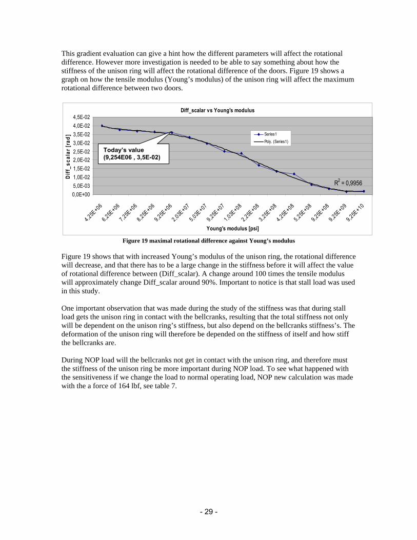
This gradient evaluation can give a hint how the different parameters will affect the rotational difference. However more investigation is needed to be able to say something about how the stiffness of the unison ring will affect the rotational difference of the doors. Figure 19 shows a graph on how the tensile modulus (Young’s modulus) of the unison ring will affect the maximum rotational difference between two doors.
Diff_scalar vs Young's modulus
R2 = 0,9956
0,0E+005,0E-031,0E-021,5E-022,0E-022,5E-023,0E-023,5E-024,0E-024,5E-02
4,25E+06
6,25E+06
7,25E+06
8,25E+06
9,25E+06
2,03E+07
5,03E+07
9,25E+07
1,03E+08
2,25E+08
3,25E+08
4,25E+08
5,25E+08
9,25E+08
9,25E+09
9,25E+10
Young's modulus [psi]
Diff
_sca
lar [
rad]
Series1Poly. (Series1)
Figure 19 maximal rotational difference against Young’s modulus
Figure 19 shows that with increased Young’s modulus of the unison ring, the rotational difference will decrease, and that there has to be a large change in the stiffness before it will affect the value of rotational difference between (Diff_scalar). A change around 100 times the tensile modulus will approximately change Diff_scalar around 90%. Important to notice is that stall load was used in this study. One important observation that was made during the study of the stiffness was that during stall load gets the unison ring in contact with the bellcranks, resulting that the total stiffness not only will be dependent on the unison ring’s stiffness, but also depend on the bellcranks stiffness’s. The deformation of the unison ring will therefore be depended on the stiffness of itself and how stiff the bellcranks are. During NOP load will the bellcranks not get in contact with the unison ring, and therefore must the stiffness of the unison ring be more important during NOP load. To see what happened with the sensitiveness if we change the load to normal operating load, NOP new calculation was made with the a force of 164 lbf, see table 7.
Today’s value (9,254E06 , 3,5E-02)

- 30 -
Table 7. Gradient of Diff_scalar during NOP load ***NOP LOAD*** PRINT RESULTS FOR GRADIENT EVALUATION FOR ALL RESPONSE VARIABLES ********** GRADIENT EVALUATION RESULTS ********** REFERENCE DESIGN = SET 1 GRADIENT RESULTS = SETS 2 TO 5 A_NORM = 1.0000 IYY_NORM = 1.0000 IZZ_NORM = 1.0000 J_NORM = 1.0000 ***** FOR THE OBJECTIVE FUNCTION DIFF_SCALAR_NORM (REF. VALUE= 1.000 ) ***** CHANGE IN VALUE (DUE TO +1% CHANGE IN DV) GRADIENT PER DESIGN VARIABLE A_NORM :-0.3825E-03 -0.3825E-01 PER DESIGN VARIABLE IYY_NORM :-0.1656E-02 -0.1656 PER DESIGN VARIABLE IZZ_NORM :-0.1475E-05 -0.1475E-03 PER DESIGN VARIABLE J_NORM :-0.1947E-05 -0.1947E-03
As shown in table 7, is the gradient for all design variables larger for the NOP load than it was during stall load, another important thing to notice is that in NOP load has the bending stiffness,
yyI a larger gradient than the cross-section, (A), the reason for all this will be explained in the conclusion chapter below. To check how the tensile modulus of the unison ring would affect the resulting contact forces, which appear when the bellcranks hit the unison ring, new calculations with ANSYS were made, see figure 20 below.
FMAX_NODAL vs Young's modulus
0,000
200,000
400,000
600,000
800,000
1000,000
1200,000
3,25E+06
5,25E+06
7,25E+06
9,25E+06
2,25E+07
3,25E+07
5,25E+07
7,25E+07
9,25E+07
2,25E+08
3,25E+08
5,25E+08
9,25E+08
Young's modulus [psi]
FMA
X_no
dal [
lbf]
Nodal force
Figure 20. Maximum contact force as function of stiffness
As figure 20 shows, will the maximum contact force between the unison ring and the bellcranks drop as the tensile modulus (Young’s modulus) of the ring increase. The reason for the small increasing of the contact force (see marked area) is because the same amount load spreads out on fewer contact areas.
Start value (9.25E+06, 1002)

- 31 -
3.6. Conclusions With the results given, the conclusion is that the system itself is very robust, changes in the stiffness (young’s modulus) as well in the design parameters ( JIIA zzyy ,,, ) will not in a large amount affect the door angle. It has also been discovered that the most important design variables (parameters) are the cross section, A and the bending stiffness ( yyI ). As you can see in table 6
and table 7 is the maximum gradient of A and yyI depending on what load you apply. For the
stall load has A the largest gradient, and in the NOP load has yyI the largest gradient. The explanation for the difference between stall load and NOP load is because, during stall load are the bellcrank in contact with the unison ring which cause the ring to buckle rather than bend. The deformation of the unison ring is due to secondary effects (how much the bellcranks will deflect etc). During NOP load will the ring not get in contact with the bellcrank and therefore will the unison ring deflect as much as the gap allows it to. In the NOP load case is the ovalization of the ring due to the fact that the bellcranks are sliding on the bolts. Figure 21 tries to explain schematically how the unison ring will deform during stall and NOP load.
Figure 21. Schematic illustration of how the unison ring will deform during stall and NOP load
3.7. Summary This chapter will summarize the most important information gathered from the pre-study
3.7.1. Stiffness requirements From the results and the conclusion chapter can it be concluded that the unison ring most important stiffness directions are:
• Tensile stiffness, A (EA) • Bending stiffness, yyI (along the ring, EI)
From the theory chapter about composites leads this to that most of the fibers in the composite design should be kept along the unison ring. To make sure that the composite are fiber dominant should fiber in at least 10% and maximum 60% be kept in all directions, in at least four fiber angles. The fibers in off-axis help also to stiff up the ring and prevent the ring from twist.
Stall load
Bellcrank & Unison ring in contact, continued ovalization, but more secondary effects (bend and pull in the Unison ring)
Bellcrank will glide on the pin bolt, no contact. (more pure bending in the ring)
NOP load

- 32 -
3.7.2. Design criteria for unison ring:
• Stiffness to prevent large ovalization during NOP load • Strength to be able to hold during limit loads (Ice, stall, birds, etc) • Lightweight design
3.8. Concept generation This chapter will explain the method used to generate concepts and ideas
3.8.1. Choice of cross-section From the design and stiffness requirements (see above), is it concluded that the unison ring wanted is a unison ring that has minimum of volume and a stiffness almost equivalent to today. By checking possible cross sections (see appendix C) the first thing that can be said, is that all the solid cross section are not to be chosen, since they will provide with to much volume, that even a change to composite material would have low affect on the weight reduction. The solution to weight reduction is to save as much material as possible and use it where it is best suitable, one example of that is the I-beam, which is designed for maximum bending stiffness with minimum of weight. By looking through the cross section in appendix C and with the results given from the pre-study, it can be concluded that the best suitable cross section for the unison ring would be a sandwich section. Important thing to notice is that the sandwich beam is not by itself stiffer if compared with the I beam if only the design was important. But integrated with materials such as composites (which are much lighter and stronger) has the sandwich huge advantages compared to both stiffness and weight. By letting the composite make the top and bottom surface of the sandwich and then having a light foam or honeycomb in the middle (core) combining the composite laminates together , a strong and stiff lightweight design can be achieved. See figure 22 below for a schematic picture of a sandwich beam.
Figure 22. Schematic illustration of a Sandwich
(Source: http://upload.wikimedia.org/wikipedia/commons/b/b2/CompositeSandwich.png) Another reason to choose the sandwich beam is presented in figure 23 below.
Foam or honeycomb Composite laminate

- 33 -
Weight Al/Composites [Kg]
00,5
11,5
22,5
33,5
44,5
0 0,1 0,2 0,3 0,4 0,5 0,6 0,7 0,8 0,9 1 1,1 1,2 1,3 1,4 1,5 1,6 1,7 1,8 1,9 2 2,1 2,2 2,3 2,4 2,5 2,6 2,7 2,8 2,9 3
Thickness, t [mm]
Wei
ght [
Kg]
Weight today's material with I-beam 0Weight Composite, I-beamWeight Composite, square tubeWeight Composite, Sandwich
Figure 23. Weight of different cross sections
In figure 23 has three different cross sections been compared to each other, sandwich, I-beam and square tube. They have all the same outer dimensions, otherwise it would not be accurate to compare them. The formula used in figure 22 was ρρ ALVm == and by assuming that they have the same length (L=1), could the mass equation be derived as ρρ AVm == . As shown in figure 22 is the sandwich the lightest of them, important to understand is that the I-beam and the square tube section are very similar in area. In appendix D are they with equal area. The reason for that is the middle section in the I-beam has 2t. This will make the total area of both the I-beam and the square tube equal. In my case I let the middle section in the I-beam become t, which of course would make the total area smaller in the I-beam. You might think why not make circular cross section and make the walls very thin, or a square cross section with thin walls. Or perhaps make the square section with different thicknesses around (thinner on the sides and thicker on top and on the bottom). The biggest reasons for not having these sections are following:
• Circular cross-section (hollow), difficult assembly and manufacturing of the joint area (area where the bellcrank are to be assembled, double curved area)
• Square cross-section (hollow), the idea is good, but from the results (pre-study) the bending across zzI and torsion J, were two design stiffness that had little affect on the unison rings performance. However with fibers−o0 on the sides could the buckling stability be grater if no core would be chosen.
3.9. Bolts, joints bushings, etc When generate concepts and ideas for how to assemble the bellcrank into the unison ring many problems was encountered. The first problem was how to create the block that bellcranks, bolts, bushings etc were to be mounted. Since It was decided that the unison ring would be designed as a sandwich beam, the middle would be made in foam or some other light material, and therefore must some kind of block with much stronger material be inserted where the bellcranks were to be mounted. More about the solutions will be discussed in the results chapter.

- 34 -
When designing the inserts (area where the bellcrank should be mounted) a limitation was set up, since the unison ring was to be mounted with the bellcranks that are used today and the design of the unison ring should affect the rest of the VBV system as little as possible, were the bolts (see figure 10) decided to go with the same diameter as today. Since these inserts will be the heaviest parts in the unison ring is it crucial that they are as light as possible. Therefore was it concluded that aluminum were to be chosen, the bellcrank bolt, bushings (if needed) were chosen to be in similar material as used today.
3.10. Number of layers and fiber orientation From chapter 2.4.9 - 2.4.13 were theories according to the stiffness in composite laminates explained and as written before will the global stiffness in a composite laminate be directly dependent on the fiber orientation and number of composite layers. From the pre-study was it concluded that most of the stiffness should be along the ring and the stiffness of the unison ring was more important during NOP load than during limit loads. When designing the composite concern must be taken, if the lay-up order is not symmetric about the thickness centre line, there is a high risk that the laminate will bend and or twist, when a load is applied. Another problem is that if the directions of the lay-up through the thickness have different number of orientations in the plane, modulus and strength of the laminate will be different in the x- and y-directions. From chapter 2.4.6 it was concluded that the laminate should have at least 10% and maximum of 60% of fiber in four different angles. By using the results from the pre-study can it be concluded that the value of the global stiffness (Young’s modulus) in the unison ring, should be approximately the same as today’s unison ring, to ensure that the ring will be stiff enough to prevent it from a higher ovalization. Before the global stiffness in the laminate with different fiber orientations could be calculated, was the axial and transversal stiffness the first thing that was needed to be calculated. From chapter 2.9 and 2.10, could the axial and transversal stiffness in fiber reinforced matrix be calculated.
GPaGPa
EV
EV
E
GPaEVEVE
m
f
f
f
ffmf
95,79458,7
3)63,01(
25063,0
1)1(
161,15825063,03)63,01()1(
2
1
≈≈⎟⎠⎞
⎜⎝⎛ −
+=
⎟⎟⎠
⎞⎜⎜⎝
⎛ −+
=
=⋅+⋅−=+−=
From MIL-HDBK-17-3F, ref [23] and comparison to similar materials could the shear modulus for a unidirectional composite layer be assumed to 4 GPa.
GPaG 412 = From chapter 2.4.7 and chapter 2.4.12, could the Poisson’s ratio be calculated.

- 35 -
01,001403,061,158
95,728,0
28,0
1
21221
12
≈≈⋅==
=
EEvv
v
3.10.1. Axial stiffness according to fiber orientation
From chapter 2.4.13 the axial stiffness (1-direction) can be derived according to fiber orientation. Important to notice is that each direction is only one layer of composite Axial stiffness with o0 fibers ( 0=φ )
GPaCCCCCC 159,18 )(sin)(cos)42()(sin)(cos 1122
66124
224
110_11 ≈=+++= φφφφ Axial stiffness with o90 fibers ( 90=φ )
GPaCCCCCC 14,95)(sin)(cos)42()(sin)(cos 2222
66124
224
1190_11 ≈=+++= φφφφ
Axial stiffness with o45 fibers ( 45=φ )
GPaCCCCC 20,59)(sin)(cos)42()(sin)(cos 226612
422
41145_11 ≈+++= φφφφ
Axial stiffness with o45− fibers
GPaCCCCC 20.59)(sin)(cos)42()(sin)(cos 226612
422
41145_11 ≈+++=− φφφφ
3.10.2. Global stiffness in the laminate So far has the axial stiffness for different fiber directions been evaluated, but since they only are representative in each fiber orientation and not together as composite laminate another equation is needed to evaluate the global stiffness in a laminate with all these fiber directions included. Equation (26) calculates the global stiffness in a laminate depending on how many composite layer used and in what directions they are pointing at.
Equation (26):
∑
∑
=
== n
kk
n
kkk
global
t
tCA
1
111
11
(
It is known that today’s unison ring can handle the applied loads and therefore is a lay-up and thickness that can obtain the same stiffness (stiffness modulus) wanted, from a handbook [3] could a typical value for the aluminum be evaluated. Assume the Young’s modulus for aluminum to be 70GPa, resulting that the tensile modulus (Young’s modulus) for the composite should be at least equivalent. The information about symmetrical lay-up about the centerline, leads to that each layer ( o0 , o45 , o45− , o90 ) must have even number of lay-up.

- 36 -
By assuming that a composite layer has a thickness of 0,13mm (standard thickness of pre-preg) and after testing different layer combinations two final lay-ups were estimated to be the best suitable. The first with 12 layers of o0 , two layers of o45 / o45− , four layers of o90 fibers and the second lay-up with 10 layers of o0 , two layers of o45 / o45− , four layers of o90 fibers. The global stiffness for the two lay-ups can be calculated as: Lay-up 1
( )102,53GPaa102,5277GP
20)4()2()2()12( 90_1145_1145_110_111
11 ≈≈+++
= −
k
kkkk
ttCtCtCtC
A
Lay-up 2
( )GPa
ttCtCtCtC
Ak
kkkk 23,9618
)4()2()2()10( 90_1145_1145_110_11211 ≈
+++= −
Where
mmtk 13,0= With this value can the unison ring be calculated as a beam with the same ANSYS code that was used to do the pre-study. The only thing that needs to be change is the material property. With these two lay-ups are the minimum percent fiber around 10 % and the maximum percent fiber around 60%, which is just inside the boundaries for a fiber dominated laminate.
4. Results This chapter will in brief explain the result of the concept generation, two variations of one concept will be revealed.
4.1. Result Concept generation This chapter will describe the final concept. Important to notice is that Type 1 and Type 2 are variations of the sandwich concept.
4.1.1. Sandwich concept, Type 1 The main issue after the concept was concluded (sandwich structure) was how to mount the aluminum blocks into the sandwich and how to create the joint for which the bellcranks bolt were to be mounted. Both the design criteria’s for the composites and the space limitations around the unison ring made it difficult to come up with solutions. In figure 24.1 and figure 24.2 are the new concept and today’s unison ring presented. Don’t be fooled by the look of figure 24.1, it might look heavier but it is approximately 1,5 kg lighter than today’s unison ring.

- 37 -
Figure 24.1. Final concept of unison ring Figure 24.2. Today’s unison ring As written before the final concept is based on a Sandwich structure with carbon fiber laminates on top and bottom (black colored). Between the composite layers is there a thick layer of foam, just to combine the two composite layers (yellow colored). The dark orange block is where the bellcranks are mounted, the blocks are made in aluminum. The reason why this unison ring is lighter is because of the small amount of aluminum and large amount of foam and composite material. The density of composite material is approximately 1750 3/ mkg , the foam 3/60~ mkg and the aluminum around 3/2700~ mkg . Figure 25 will give a closer look on the unison ring and give better understanding how the unison ring is made. Important to know is that figure 24 only showing a concept.

- 38 -
Figure 25 Illustration of the final concept
The idea with this concept is that the aluminum blocks are pre manufactured, then glued and bolted into the unison ring. The unison ring is of course already manufactured with foam and composite layers. Due to the shear forces between the aluminum block and the unison ring, blind bolts are mounted to take the most of this shear. One of the problems with both the blind bolts and the bellcrank bolt were the space issue around the unison ring, especially inside the unison ring where booster case is to be mounted (inside the unison ring). The reason why the actuator block bigger than the door block, is because of the larger actuator bellcranks, and also because that the applied force is larger in the actuator block than in the door block. One problem with the door block is the manufacturing, the complex geometry makes it harder to manufacture. The only reason why the door block looks as it does is because the applied force are much lower and therefore can more material be cut away, reducing more weight. The core in the sandwich can be made in two different variations, either with foam or a honeycomb structure. The benefits of using foam are because it is easier to manufacture since the shape must be curved and also because there is more surface to attach the glue on, which will make the bonding stronger. With honeycomb core can the unison ring be much stronger and stiffer compared to weight, but the difficulties by making the core in honeycomb is due to manufacturing and gluing the honeycomb on to the composite.
Composite material (Carbon/Epoxy)
Core (foam or honeycomb)
Actuator block (aluminium)
Door block (aluminum)
Bellcranc bolt (inco 718)
Bushings (steel)
Upper hole
Huck blind bolt (steel)
AREA OF BOOSTER CASE

- 39 -
4.1.2. Door and Actuator block. Figure 26.1 and figure 26.2 shows the aluminum blocks in more detail.
Figure 261. Door block Figure 26.2. Actuator block
For the same reason why the actuator block in general are bigger are also the gap size and the slot in the actuator block is also larger than the door block. In general is the actuator block more robust in its design (more material) because of the larger forces that the actuator bellcrank is subject to. Slot 1 is a milled hole which a part of the bellcrank bolt are to be fit in, this slot is to make sure that the bellcrank bolt don’t rotate. The retaining slot is where the retaining ring is mounted to stop the bellcrank bolt from moving upwards. The limitation here was the geometry of the retaining ring, though it was concluded that retaining rings were used in aerospace no retaining ring width that small diameter could be found, the question remain whether it is possible to get customized retaining rings or not. The main issue with the upper hole was to assume the accurate diameter, since they are drilled in the composite had the design criteria for bolted joints be included. From chapter 2.4.6 was it concluded that the width of the composite should be at least 4d. Since the width is approximately 33,02mm can the maximum diameter of the hole be approximately 8,255mm. A larger diameter would affect the bearing strength of the hole and a smaller would affect the diameter of the bellcrank bolt. The upper bushing holes in the door and in the actuator block must be large enough to make sure when the bushings are mounted the bellcrank bolt does not get in touch in these upper holes (see figure 27.1 and figure 27.2) Figure 27.1 and 27.2 shows the aluminum blocks with the bushings and retaining ring inserted.
Slot 1 Retaining ring slot
Bushing hole Bushing hole
Upper hole
Upper hole

- 40 -
Figure 27.1 Door block Figure 27.2 Actuator block The bushings are mounted to protect the soft aluminum against wear and the high contact forces which occurs during limit loads. For this installation of the bushings, same bushings can be used that are mounted on today’s unison ring. The bushings are mounted with a grip tolerance, making sure that they do not move during operation of the unison ring. The grip tolerance must be set to meet the big temperature range which the unison ring can be subjected to. One issue regarding the bushings were if it was possible to not use bushings and letting the bellcrank bolt directly get in contact with the aluminum. Since the bellcrank bolt are assumed to not rotate the wear against these surfaces can be approximated to zero, and therefore will the bushing be unnecessary. However during loading will the bellcrank get in contact and hit the bushing (see marked area in figure 27.2). According to the FEM analysis appendix I and appendix L the door block and actuator block will not be affected by high stresses. But since these calculations were made with rough approximations of the force and boundary conditions, caution must be taken with the stress and displacement values (see table 11 and table 12) The reason why the bushings are mounted are most due to the fact that it is easier to replace a bushing than the aluminum block and also to reduce the bearing stress since the diameter of the hole gets larger.
4.1.3. Bellcrank bolt and retaining ring The bellcranks bolt which connects the bellcrank with the unison ring can bee seen in figure 28. It is similar to the bellcranks bolt that is used today, but without any threads and the head are replaced by two flanges (prevent the bolt from rotating), the material is Inconel 718. During the design of the bellcrank bolt were there suggestions with only one flange, the reason for keeping two was mostly because two flanges preventing the bellcrank bolt from rotating is better than one.
Gap Gap
Width
Contact area during loading

- 41 -
Figure 28. Bellcrank bolt Figure 29. Retaining ring The retaining ring (see figure 29) is made of steel and it is mounted to prevent the bellcranks bolt from moving upwards. The ring can be in two variations, either as a spiral or as a snap function see [16], [17] for examples. As written earlier, the issue with the retaining ring is if it is possible to get it customized.
4.1.4. Blind bolt (Huck fasteners) Since the aluminum blocks are glued between the composite and the bellcrank bolts are mounted inside these aluminum blocks, will there not be a large axial pressure clamping the two composite laminates together, which result in increased shear force between the composite and the aluminum. To reduce the high shear stress between the aluminum blocks and the composite, are blind bolts (Huck fasteners) mounted on each side of the aluminum block, see [14]. To ensure that there will be enough space beneath the unison ring, are the blind bolts mounted from the bottom making the end pointing upwards. The difficulty by using the Huck blind bolts are the clearance fit (chapter 2.4.6) since blind bolts require a tight fit to be able to work it could be problems if the tolerance between the hole in the composite and in the aluminum aren’t the same. One possible solution would be to drill the hole in the aluminum block and in the composite in one single operation. Figure 30 shows the aluminum blocks with retaining ring, bushings, blind bolt and bellcrank bolt mounted.

- 42 -
Figure 30. Door block assembly
P is the tangential force which are applied during loading (both NOP and limit loads, see figure 16). The red marked double arrow are showing the free bolt bending length (see figure 33.1 and figure 33.2), which is used for the bolt bending calculation.
4.1.5. Sandwich concept (Type 2) Figure 31 shows another variation of the same sandwich concept (Type 2). As shown in the figure are there no blind bolts mounted, the composite laminates are clamped directly with the bellcrank bolt, by making the bellcrank bolt threaded and screw it into the inner composite ring. Due to the fact that bolts cannot be threaded directly in to the composite, are steel bushing with threaded inner diameter mounted (glued)
Figure 31. Sandwich concept Type 2. Figure 32. Door & actuator block
P
Door block Actuator block

- 43 -
As shown in figure 32 are the aluminum blocks reduced a little bit and instead has a thicker layer of composite been introduced. The length of the aluminum blocks has also been reduced, since no outer pin bolts or rivets are needed.
4.1.6. Aluminum blocks (Type 2)
Figure 33.1. Door block assembly Figure 33.2. Actuator block assembly In figure 33.1 and figure 33.2 are a more detailed view of the unison ring mounted with bushings and bolt shown. The bolt is wider in the beginning (to fit the composite hole) and threaded in the end to be screwed into the bottom bushing, the bushings are glued into the composite to prevent them from rotating. Caution must be taken and accurate tolerances must be used to prevent the composite from damage. The read marked area are to show that there is a grip between the surfaces. The bushings in the aluminum are only mounted to protect the aluminum against impact from the bellcrank when they get in contact, the inner diameter of these bushings are also slightly larger making a small gap to the bellcrank bolt. Important to notice is that the radial gap between the bellcrank bolt and the bushings mounted in the aluminum block are set so it is small enough to take some of the load when the bellcranks are loaded, otherwise would the bending in the bolt be too high. The high bending stress in the bolt is a result of the increased free bolt length (see red marked arrow). The reason for this concept is to use the strength of the composite and let the applied force in the bellcrank bolt be transfer directly out and into the composite, resulting that most of the stress will be in the composite and not transferred into the foam. One thing that also has to be considered is that the area between the composite ring and the aluminum blocks (both type1 and type 1) is very stiff, resulting that the glue between these areas has very little clearance to move. To avoid high stresses is it therefore advantageous if a more flexible material could be inserted between the composite ring and the aluminum blocks, allowing the glue (area around the glue) to move.
Threaded Threaded Gap
Gap

- 44 -
5. Calculations This chapter will explain the calculations that were used to verify that bolts, bushings, aluminum blocks and the unison ring in general would hold for the maximum load. Bearing stress, bolt bending calculations were made to ensure that the diameter of the bolts and hole were large enough to hold for the load, FEM analysis of the unison ring with calculated global stiffness were made to ensure that the composite would hold for the maximum load case (ice load). Since the installation of the bushing and bolt are approximately the same as previous unison ring, same calculations procedure was used (see appendix E-G), the contact pressure calculation can also be found in [18] .Important to notice is that the dimensions used in these calculations are approximated from the 3D CAD models. The material data used in these calculations are approximated from handbooks [22] and from ref [27]. The maximum load that is applied during loading is lbfP 5625tan = which occurs during ice load. ( tanP ) is applied on the actuator during ice load (see figure 16 for direction).
YSP is the maximum allowed force and actP is the actual force applied in this case tanPPact =
act
actYS
PPP
MS−
= , (margin of safety) (29)
5.1. Material data The materials used are from DOT/FAA/AR-MMPDS-01 ref [22] if not otherwise noted
Part Material Yield stress [Mpa / ksi]
Bearing stress [Mpa / ksi ], ref [27]
Aluminum block
7050 Aluminum Alloy, AMS4108, Hand Forged 400 / 58
Bushings A-286 Steel Alloy, AMS 5737 655 / 95 Bellcrank bolt Inconel 718, AMS 5662 1034 / 150 Composite Carbon fiber, Epoxy matrix 400 / 58
5.2. Bolt bending/shear
5.2.1. Bellcrank bolt in type 1 Bolt bending calculation for the bellcrank bolt in type 1 can be seen below: Maximum load during ice load: lbf5625=YSP
Minimum 2
1;4
64)1()1(
644
)1(4
3
3
LYS
aPd
a
dYS
daIYS
Pbolt
YSs
sbolt
s
boltYS =
−=⇒
−=
−=
π
π
: (28)
2923,0=sd in (7,426 mm) Difference: 0,3113 – 0,2923 = 0,019 in (0,483 mm)

- 45 -
The minimum diameter sd of the bellcrank bolt can therefore be 7,426mm which would lead to a margin of safety around zero. By using the same diameter as today’s bellcrank bolt the margin of safety becomes around 0,21. The calculation above has been done according to appendix E The bolt shear can be seen in appendix D, by using the same diameter 0,3113 in (7,907 mm) the
Margin of safety becomes 21,15625
56256.12444≈
−=
−=
act
actYS
PPP
MS
lbf12444,6=YSP is the maximum load that can be applied if the bolt should hold for shear.
5.2.2. Bellcrank bolt, type 2 Since the geometry of the bellcrank bolt in type 2 is more complex, different thicknesses along the bolt are the shear and bending calculation difficult to estimate. The best calculation in this case would be with FEM and therefore are no hand calculations made. In chapter 9 is there an explanation for why the bolt should hold.
5.2.3. Blind bolts (Huck fasteners) in type 1 From [25], [26] is the material of the Huck blind bolt given (A286 Stainless Steel). From ref [22] is the yield strength given ksiYSA 9528 = By using a diameter of 0,311in (7,899mm) and with the equation in appendix D, can YSP be calculated, see figure 34 for a schematic illustration of the Huck blind bolt
36481,96N)(47,820134
93500311,023
22
286 lbfYSAP AsYS ≈
⋅⋅==
π
Figure 34 Schematic illustration of the Huck blind bolt
46,04579,05625
56258201≈≈
−=MS
Important to notice is that the calculation above is a rough approximation.
Shear area
P

- 46 -
H = 50,546
b= 33,02
[mm] t
h = 47,95
yyI
zzI
Figure 35 Cross section of unison ring
5.3. Contact pressure (Bearing strength) By using appendix F as reference can the bearing strength be calculated, important to notice that the dimensions are slightly different. Appendix D-F should only be used as a guide reference on how to calculate. The force P is divided on to surfaces, by assuming that the force is equally divided on these two surfaces will the expression for the maximum allowed force look like this:
2⋅⋅⋅= tdYSPYS (30) Where d is the diameter of the hole, t is the grip length and YS is the materials yield strength. d and t will together be the contact area for which the force P will be applied. Table 8 below shows the results from the contact pressure calculations (bearing strength). The calculations for both type 1 and type 2 can be found in appendix P. Important to notice is that for the composite, was the bearing strength assumed to be MPabs 400=σ ref: [27]. Table 8 Result of the contact pressure calculation (Bearing strength)
Contact pressure Pact [lbf]
PYS [lbf] MS (Margin of Safety)
Top bushing to aluminum (type 1) 5625 15154 1,69 Bellcrank bolt to top bushing (type 1) 5625 15365 1,73 Bottom bushing to aluminum (type 1) 5625 13754 1,44 Bellcrank bolt to bottom bushing (type1) 5625 13946 1,48 Bellcrank bolt to composite (type 2) 5625 8266 0,47 Bottom bushing to composite (type 2) 5625 9170 0,63 Bellcrank bolt to bottom bushing (type 2) 5625 10433 0,85
As shown in table are the forces in [lbf] for Newton [N] please see appendix P
5.4. Result FEM analysis
5.4.1. Unison ring With the results from chapter 3.12.2 and the assumed dimension of the cross section could the deformation of the unison ring be calculated. Figure 35 shows the cross-section data. Table 9 shows data for the two lay-ups.
btAAArea 2:)( =
[ ])3:(2
22
referencehtbI yy ⎟⎠⎞
⎜⎝⎛=

- 47 -
Table 9. Data for the two lay-up types Lay-up
Thickness [mm]
Area [mm2]
Second moment of area, Iyy [mm4]
Young's modulus, E [GPa]
1 2,6 171,7 98695,57 102,53 2 2,34 154,53 88825,99 96,23
By changing E and yyI in the ANSYS code could deformations and contact forces be calculated for the sandwich composite beam, the results of the displacements can be seen in table 10, figure of the displacements can bee seen in appendix G and appendix H. The contact forces can bee seen in appendix O. Important to notice are that both appendixes G, H and O are for lay-up 1. Table 11 shows the maximum stress in the unison ring. Important to notice is that both the displacement and the stress are calculated with the beam unison ring modeled with beam elements, caution must therefore be taken when reading these results. Table 10. Result FEM analysis Unison ring (displacement)
Unison Ring
Load case
Radial displacement (UX) [in / mm]
Circumferential displacement (UY) [in / mm]
Composite (lay-up 1) NOP 0,067631 / 1,718 0,070734 / 1,797 Stall 0,145679 / 3,700 0,177580 / 4,511 Composite (lay-up 2) NOP 0,071449 / 1,815 0,074164 / 1,884 Stall 0,147695 / 3,751 0,181593 / 4,612 Aluminum (Today's) NOP 0,068442 / 1,738 0,070808 / 1,799 Stall 0,146104 / 3,711 0,173812 / 4,415
The Yield strength are calculated by using the GPaEGPaE 23,96,53,102 21 == and the compressive design strain %3,0=ε With Hooke’s law )9,41(7,288)1,44(6,307 21 ksiMpaandksiMpaE ==⇒= σσεσ Table 11. Results max stress unison ring
Unison ring
Load case
Yield strength (compressive) [MPa /
ksi] Stress in tension
[MPa/ksi] Margin of
safety Composite (lay-up 1) NOP 307,6 / 44,1 36,5 / 5,3 0,87 Stall 307,6 / 44,1 146,2 / 21,2 0,52 Composite (lay-up 2) NOP 288,7 / 41,9 46,2 / 6,7 0,84 Stall 288,7 / 41,9 151,0 / 21,9 0,48 The stresses in table 11 are calculated by taking out the maximum moment force for an element in the unison ring and then by hand calculate the maximum stress tension. For calculation see appendix P. Important to notice is that the maximum compressive stress are assumed to be the limit stress that the unison ring can take in tension.

- 48 -
The different lay-ups were also checked against the maximum rotational difference between two doors, see table 12 below. Table 12. Comparison of rotational difference (bellcrank) between composite and aluminum
Unison ring Load case Rotational difference [rad / grad] Composite (lay-up 1) NOP 0,0158051 / 0,91 Stall 0,0363515 / 2,08 Composite (lay-up 2) NOP 0,0166278 / 0,95 Stall 0,0371869 / 2,13 Aluminum (Today's) NOP 0,0253891 / 1,45 Stall 0,0356299 / 2,04
As seen in table 12 are the rotational difference in the bellcranks lower in the composite ring during NOP load than in the aluminum ring. The reason is most likely that the composite ring is stiffer than the aluminum ring. Why lay-up 2 has larger rotational difference than lay-up 1, are because the tensile modulus, tensile stiffness and bending stiffness are lower. During stall load is the rotational difference in the bellcrank larger in the composite rings than in the aluminum ring. One explanation could be that sandwich structure in the composite ring (thin laminates) reduces both the tensile stiffness (EA) and bending stiffness (EI) a little bit, which lead to more bending in the bellcranks.
5.4.2. Aluminum block FEM analysis To verify that the aluminum blocks (door and actuator) would hold for both the radial tanF loads (figure 16) and the loads during contact, separate FEM analysis were made, one for the door block and one for the actuator block.. The results can be seen in appendix I to appendix N. The stress is measured in [psi] and the displacement in [in] Table 13 and table 14 shows the result from the FEM analysis. The difficulty here was to model up accurate boundary conditions and the applied load, rough estimations were made and therefore should the results given in both table 13 and 14 be taken with caution.
)0,58(400 :aluminum stress Yieldmm25,4in 1
Pa6894,75731
y ksiMPa
psi
≈≈≈
σ
The boundary condition and load used can be seen in figure 36.1 and 36.2 below, here are the four edges given the degree of freedom UX = UY = UZ = 0 and free in all rotations.

- 49 -
Figure 36.1 Stall load, door block Figure 36.2 Contact load, door block Table 13. Result FEM analysis (von Mises)
Load case Part Sandwich concept
type Load [lbf / N] von Mises stress
[psi / MPa]
Ice load Door block Type 1 5625 / 25021 64493 / 445
Ice load Actuator block Type 1 5625 / 25021 52046 / 359
Contact force Door block Type 1 1000 / 4502 87452/ 603
Contact force Actuator block Type 1 1000 / 4502 24638 / 170
Table 14. Result FEM analysis (displacement)
Load case Part Sandwich
concept type Load [lbf / N] Displacement UX, UY [in / mm]
Contact force Door block Type 1 1012 / 4502 0.00199 / 0.051 , 0.0176 / 0.446
Ice load Door block Type 1 5625 / 25021 0.00785 / 0.199 , 0.0058 / 0.146
Contact force Actuator block Type 1 1012 / 4502 0.00111 / 0.028 , 0.0079 / 0.207
Ice load Actuator block Type 1 5625 / 25021 0.00673 / 0.171 , 0.0034 / 0.086
Important to notice is that these calculations were rough approximations, the idea with these calculations was to make sure that the estimated design of the aluminum blocks was strong enough. Caution must be taken, the stresses represented here are the maximum stress that occurred, these needs to be evaluated with the figures in appendix I to N.

- 50 -
6. Manufacturing This chapter will explain different manufacturing methods that can be used for the composite unison ring. In chapter 2.4.8 were different manufacturing methods described for a standard aerospace composite. Depending on the choice of material (pre-preg etc) can different methods be used. The standard approach would be using the pre-preg, which also might be the easiest, however are there no proofs so far that other manufacturing methods could be excluded. The reasons why the manufacturing methods already were narrowed down to three possible methods were due to the fact that it already from the beginning assumed that advanced composites were to be used. The manufacturing of the aluminum blocks can either be milled from pre-cut aluminum bars [13] or first extruded and then milled to get the final design. The bushings and bolts can be turned from rods.
7. Costs The cost for an aerospace composite is usually around 5000 SEK per kg for a complete composite design (675,68 USD). But due to the unison rings complexity and therefore might required specialized manufacturing methods, can the cost be estimated higher. How much the ring will cost can not be estimated (due to choice of manufacturer, manufacturing method etc) but a rough comparison between the estimated cost for the composite and today’s unison ring can be made. If it is assumed that 5000 SEK (per kg) is the cost for the complete composite, 500 EUR per set of pre thermoformed and cut foam insert the following data can be estimated. Estimated cost for the Composite ring Price approx composite 5000SEK/Kg Cost composite (raw material ~2kg): 10000 SEK (1351,35 USD) Cost foam: 500 EUR, 4585 SEK (619,59 USD) Cost Composite: )95,1970(14585100004585 USDSEK=+ 14585 SEK is the total cost for the composite unison ring including the foam and without the aluminum blocks. Cost Aluminum blocks: If it is assumed that the cost for one aluminum block are the total cost today’s unison ring, divided by the numbers of blocks that can be manufactured from today’s unison ring. The cost per block would just be the total cost of the unison ring, 45310,2 SEK (6123 USD) divided with the number of aluminum blocks that could be manufactured from today’s unison ring. Number of blocks from today’s unison ring: ~ 46

- 51 -
Cost per block: SEKSEK 100112,100146
45311≈≈
The numbers of aluminum blocks are 12 therefore will the cost be around
SEK12012100112 =⋅ (1624 USD) This is a very rough approximation and it is assumed that the total manufacturing cost is spread even over the whole unison ring. Important to also notice is that in this cost is the raw material cost included (7050 Aluminum Alloy, AMS4108, Hand Forged). The total cost for the Composite unison ring can therefore be approximated to:
SEKtTotal 265971201214585:cos =+ To include the final machining operations (accurate tolerances of holes etc) and that the cost for the composite (5000 SEK) can be greater, a factor of 30 % are added. Cost with 30% : 34576,1 SEK ~35000 SEK.
Estimated cost saving: %2323,0228,045310
4531035000−≈−≈−≈
−
8. Weight reduction By putting material data on every component in the unison ring, the total weight could be approximated, the weight was approximated directly in the CAD software The weight of today’s unison ring: ~5.1 kg Type 1 The total weight of the unison ring (including bolts, bushings etc): ~3.6 kg
Weight reduction: 1,5 kg ⎟⎠⎞
⎜⎝⎛ −≈−≈
− %29,0%294,01.5
1.56,3
Type 2 The total weight of the unison ring (including bolts, bushings etc): ~3.2 kg
Weight reduction: 1,9 kg ⎟⎠⎞
⎜⎝⎛ −≈−≈
− %37,0%373,01.5
1.52,3
Important to notice is that this weight reduction is just a rough approximation from the 3D CAD system.

- 52 -
9. Discussion This chapter will discuss the concept, things that are important, different problem areas, the concepts different strengths and weaknesses. To design a component in composite material, the components main function and requirements has to be evaluated carefully, since composite materials can give us more choices of opportunities to optimize our designs. The benefit is that designs can be optimized in a larger range and modified to meet its purpose better, however since there are more parameters involved, design in composite can quickly become a challenge (depending on the load case, 1-D, 2-D, 3-D). From the theory chapter and the method chapter it was concluded that a sandwich concept was the best choice, compared to the most common cross sections (tube, rod, square, I-beam, etc). However even if a sandwich are to be chosen, thin shells of composite on the sides might be necessary. In this thesis I assumed the unison ring to have an open cross section (no protective layer on the sides), but depending on the requirement of toughness against damage some sort of protective layer may be needed. In the pre-study was it found out that changes in stiffness (tensile modulus, EA, EI) of the unison ring would have a little affect on the opening door angle (which was set as the main function of the unison ring). I also found out that the stiffness of the unison ring had more affect whether the bellcrank would get in contact with the unison ring or not. In brief gave the pre-study following:
• The opening angle of the doors (during limit load) is directly depended to the deformation of the bellcrank.
• The ovalization of the unison ring has very little affect on the opening of the doors. The knowledge from the pre-study lead me to the decision to design the unison ring with a cross-section that would add minimum of weight and meet the design stiffness’s best, therefore was it chosen that the mechanical properties along the ring should be equivalent today’s unison ring (equivalent tensile modulus along the ring). The difficulties were to match the fiber domination criteria against the tensile modulus and weight issue. Lay-up 1 with twelve o0 fibers, two
o45± fibers and four o90 fibers are just above and below the limits of %60%10 ≤≤ fibers according to the fiber domination criteria, to spread out the fibers a little bit better without adding more weight, two layers of o0 were taken away (lay-up 2). Even if the tensile modulus, tensile stiffness and bending stiffness were reduced in lay-up 2, were the resulting displacements, stresses and bellcrank rotation not noticeable affected. Important to notice is that these calculations were based on the general beam model in ANSYS and a laminate thickness of 0,13mm was estimated, therefore are more studies needed before final conclusions can be made. However the total laminate thickness can be estimated to be around 2,5mm. When it comes to the concept generation were there many things that I had to consider, everything from manufacturing, clearance and tolerance issues to pure strengths issues had to be considered. One of the biggest problems that I encountered was how to design the area were the bellcrank bolt was to be mounted. In type 1 was it solved by mounting the bolt under the composite without threads and with flanges to prevent the bolt from rotating. To lock the bolt axially I used a retaining ring which is clamped into a milled groove. It is obvious that the entire load will be transferred from the bolt into the aluminum block and then out into the composite.

- 53 -
The glue between the aluminum block and the composite will be exposed to high shear stresses which it probably would not hold for. To solve that issue I designed two holes on each side of the bellcrank bolt, were two blind bolts are to be mounted, to take the most of the shear load. One difficulty with interference fit fasteners are the high risk of delamination and other damages around the hole, therefore has a general requirement of ( [ ]mmmm 100,0000,0 +− ) clearance fit been established, see chapter 2.4.6 and [15]. I do not think that the clearance fit itself would make any larger problem, but caution must be taken since the hole is going through the aluminum as well. The hole cannot be drilled in one single operation since the cutting data for composite and aluminum are different. The solution would be to drill the hole in the composite laminates and in the aluminum in two separate operations, this operation is done before the aluminum block is glued into the unison ring. During the glue operation between the composite and the aluminum block, must one of the blind bolts be mounted to achieve the accurate tolerance. The reason why the bellcrank bolt are designed as shown in figure 30 are because there are a design rule for composite that says that for a bolted joint the width of the composite should at least be four times the hole diameter. Important to notice is that the relation between the hole diameter and the width are dependent on the lay-up (proportions on the [ ]oo 45,0 ± ) [15]. Since we know that the width is 33,02 mm the maximum allowed diameter of the hole would be around 8,26 mm. One problem with small holes is that it could be hard to find retaining rings with such small diameter, caution is needed perhaps must the hole be slightly larger than 8,26 mm, which then would affect the bearing strength. In overall is type 1 a good variation of the sandwich concept, it reduces hole diameters and no threads are needed, however the disadvantage with type 1 is the load transfer from the bellcrank bolt to the unison ring. The better solution would be a load transfer directly from the bellcrank bolt to the outer and inner composite laminate, since that would spread out the load were the design are strongest. In type 2 which is a variation of the sandwich concept, have the blind bolts been replaced by a threaded bellcrank bolt. The main idea was to use the strength of the composite and some how clamp the composite laminates with the bellcrank bolt. What I mean about use the strength of the composite is related to how the applied force on the bellcrank bolt will be transferred. In type 2 will the load be transferred directly to the composite since the bellcrank bolt are designed to get a grip tolerance between the upper composite laminate and the bushing mounted in the inner composite ring. The bushings mounted in the aluminum block are just to protect the aluminum when the bellcrank get in contact. The advantages with this solution is fewer parts, the composite laminates is clamped together and of course that the load from the bellcrank bolt will be transferred out to the composite instead of going through the aluminum block and further to the foam, which will prevent the upcoming of huge shear forces in the glued area (between the aluminum block and the composite) to keep the aluminum block in place. One difficulty with type 2 is that the bolt might be to thin in the end (threaded area) and therefore might not be able to handle the bending and shear stress that occurs when the bolt is loaded ( tanF ). However this issue can be partially solved by designing the bushings in the aluminum so the gap between these and the bellcrank bolt is small enough (see figure 35.1 and figure 35.2). During loading will the bolts deflection be dependent on the gap size.

- 54 -
The reasons for making the composite thicker above and beneath the aluminum blocks are because of the contact pressure (type 2). Important to notice is that all components chosen in the variations (type 1 and type 2) are not checked with the specified hardware selection criteria for an engine, since these are different from engine to engine. However, the components are checked so the providers somehow have certified products for aerospace applications. One issue with mechanically fastened joints between carbon/epoxy and aluminum is the galvanic corrosion, this occur because of big dissimilarity in electrochemical potentials between these two. Galvanic corrosion is something that has to be considered and the carbon/epoxy should never be in direct contact with the aluminum. Usually is a layer of glass-fiber put between to prevent the galvanic corrosion to occur, but since there will be glue between the composite and the aluminum blocks the glass fiber may not be necessary. The cost approximation that was made earlier is only a rough approximation, how much the unison ring will cost cannot in this stage be estimated, new and more accurate calculations are needed to verify the real cost. However the calculations made here in this thesis gives in overall a good overview on where the cost might end up. Important to notice is that the FEM analysis and hand calculation made on the unison ring are based on beam elements and since the results are directly dependent on the design as well on type of mesh and boundary conditions, caution must be taken. No calculations of the local sandwich failure modes has been made, the damage tolerance aspects has been treated by a choice of compressive strain, therefore is further studies needed.
9.1. Concept evaluation matrix Table 13 is showing a concept evaluation between the two sandwich variations Table 13. Concept evaluation matrix (0: = Possible/Needs further investigation, +: = Acceptable, -:= Not Design criteria Type 1 Type 2 Limit loads (unison ring) + + NOP load (unison ring) + + Weight + + Cost 0 0 Manufacturing of aluminum block (easy manufacturing, time saving etc) + + Manufacturing of sandwich beam (easy manufacturing, time saving etc) + + Bolt bending/shear + 0 Bearing strength + + Composite design criteria 0 0 Design for assembly (Poka-yoke, Murphy proof) + + Aerospace standard attaching parts 0 0

- 55 -
10. Conclusions This chapter will explain the conclusions. It can be concluded it is possible to use composite materials to achieve weight reduction in the unison ring. From the results given both in the pre-study, from the calculations and analysis made, points out that it is possible to design the unison ring in composite material. Compared to the two variations created (type 1 and type2), small changes might be necessary, dependant on the engine space envelope the design of unison ring to be used. I believe that a unison ring in a composite sandwich structure overall is feasible, but as written before, dependant on the application, different attachments may be required. However even if the main issue is solved whether or not we can make the unison ring in composite, remains the unison ring to be analyze and optimized further before a final design can be achieved.
11. Proposal for further work This chapter will explain some proposals for further work. The research performed in this thesis has been limited concept study, therefore are a couple of suggestions for further work included.
• Analysis of a complete unison ring (sandwich beam including aluminum blocks etc) • Investigate the influence of vibration, fatigue calculations etc. • Investigate the thermal effect. • Perform a more and accurate cost estimation • Investigate the requirement of the designs damage tolerance. • Check in more detail different suppliers and manufacturers. • Failure mode analysis (FMEA)

- 56 -
References [1] Hull, D & Clyne, T. W. (1996) Introduction to Composite Materials, second edition,
Cambridge University Press, ISBN 0 521 381908, ISBN 0 521 38855 4. [2] Ashby, Michael F. (2005) Materials selection in Mechanical Design, third edition,
Elsevier Ldt, ISBN-13: 978-0-7506-6168-3, ISBN-10: 0-7506-6168-2 [3] Sundström, Bengt. (1998) Handbok och formelsamling I Hållfasthetslära, Institutionen
för hållfasthetslära KTH, Fingraf AB Södertälje. [4] van Beek, Anton. (2006) Advanced engineering design Lifetime performance and
reliability, Delft University of Technology Mechanical Engineering, TU Delft, ISBN-10: 90-810406-1-8, ISBN-13: 978-90-810406-1-7. [5] Johanson, Hans. (2006) VOLS:10036370, Volvo Aero [6] Johansson, Hans. (2006) VOLS:10036371, Volvo Aero [7] Johansson, Hans. (2006) VOLS:10046888, Volvo Aero [8] Björneld, Frida. (2006) VOLS 10027887, Volvo Aero [9] Royce, Rolls. (2005) The Jet Engine, Rolls-Royce plc, ISBN 0 902121 2 35 [10] Wikipedia, http://en.wikipedia.org/wiki/Compressor_stall , (Accessed 2008-01-04) [11] Hexcel, http://www.hexcel.com/NR/rdonlyres/230A6C2A-FDFA-4EC7-B048-
E4EB28E3BC8C/0/PrepregTechnology2.pdf , (Accessed 2008-01-04) [12] Hexcel, http://www.hexcel.com/NR/rdonlyres/396584FF-103B-49DE-A4A0-
C917D3F73202/0/HexcelAerospaceselectorguideprepregsandfabrics.pdf , (Accessed 2008-01-04)
[13] Online Metals,
http://www.onlinemetals.com/merchant.cfm?pid=1122&step=4&showunits=inches&id=999&top_cat=60, (Accessed 2008-01-04)
[14] Alcoa,
http://www.alcoa.com/fastening_systems/aerospace/catalog/pdf/specifications/BBCatalog-9-2000.pdf (Accsessed 2008-01-04)
[15] ESA Publications Division, PSS-03-203 Structural Materials Handbook Vol. 1 Polymer
Composites, Issue 1, Rev, April 1995, Structures and Mechanics Divisions, European Space research and Technology Centre
[16] Smalley, http://www.smalley.com/retaining_rings/search_for_a_ring.asp (Accessed
2008-01-04)

- 57 -
[17] American Ring & Tool Co, http://americanring.net/military_products.aspx (Accessed 2008-01-04)
[18] Björk, Karl (2003, 5th edition,), Formler och Tabeller för Mekanisk Konstruktion, Karl
Björks Förlag, Hållfasthetslära för teknologi och konstruktion. Elementär Mekanik. [19] MatWeb, http://www.matweb.com/search/DataSheet.aspx?MatID=17403
(Accessed 2008-01-04) [20] MatWeb, http://www.matweb.com/search/DataSheet.aspx?MatID=9393
(Accessed 2008-01-04) [21] MatWeb, http://www.matweb.com/search/DataSheet.aspx?MatID=13247 (Accessed 2008-01-04) [22] Richard C. Rice, Jana L. Jackson, John Bakuckas, Steven Thompson (2003),
DOT/FAA/AR-MMPDS-01 (MMPDS), U.S. Department of Transportation Federal Aviation Administration, Office of Aviation Research Washington, D.C. 20591
[23] DEPARTMENT OF DEFENSE HANDBOOK (2002) MIL-HDBK-17-3F Volume 3 of 5, Department of Defense United States of America.
[24] Dr. S. Li (2002),
http://personalpages.manchester.ac.uk/staff/shuguang.li/download/CompositesI_Notes_Laminate_Theory.pdf , (Accessed 2008-01-04)
[25] Alcoa,
http://www.alcoa.com/global/en/products/info_page_pop.asp?info_page_id=171&prod_id=807 (Accsessed 2008-01-04)
[26] Alcoa,
http://www.alcoa.com/fastening_systems/aerospace/catalog/pdf/standards/BLB107J.PDF (Accsessed 2008-01-04)
[27] Crews, JR. J. H & Naik R. A (1987), Bearing-Bypass loading on Bolted Composite
Joints, NASA Technical Memorandum 89153, NASA Aeronautics and Space Administration, Langley Research Center, Hampton Virginia 23665.
[28] Onlinemetals, http://www.onlinemetals.com/basket.cfm?pidadd=1122&CFID=7223875&CFTOKEN=66658948 (Accessed 2008-01-04) [29] Mallick, P.K, (1988), Fiber-reinforced composites: material, manufacturing and design, Department of Mechanical Engineering, University of Michigan, MARCELL DEKKER, INC

- 58 -

- 59 -
APPENDIX Appendix A, displacement, during NOP
Figure A1. Radial displacement [in]
Figure B2. Circumferential displacement [in]

- 60 -
Appendix B, Displacement (Stall load)
Figure B1. Radial displacement
Figure B2. Circumferential displacement

- 61 -
Appendix C, Moment of sections
Figure C. Moment of section (source: Michael F. Ashby, Material Selection in Mechanical Design, third edition, 2005)

- 62 -
APPENDIX D. Bolt shear calculation
REFERENCE: VOLS10036370
YSP =12444.6 lbf
Bolt Shear strength:
32 bolt
SYSYS
AP =
Shear area: 2
4 sS dA π=
Max Allowed Bolt Shear Load
Transverse load: P
Bearing width: W = 0.625 inBolt shaft free length: L = 0.872 inBolt shaft min diameter: in0.3113=sdBolt yield stress: [ ]22 :Ref=boltYS
Ring, Unison-assembly.VOLS:10026697-04 Bolt thread size: 0.375-24 UNJF - 3A Bolt, Externally relieved body.VOLS:10023016-03Bearing modified MS14103-8: VOLS:
Geometry, material properties and loads
2076.0 inA S =
t3
Dh, db2
t2db1
t1
ds
W
tLE
Ds
L
dm
P
dr
DF
dF
t3
Dh, db2
t2db1
t1
ds
W
tLE
Ds
L
dm
P
dr
DF
dF

- 63 -
APPENDIX E, Bolt bending calculation
PYS 7912.0 lbf=PYS8 YSbolt⋅ I⋅ l⋅
l2 a2−( ) d s⋅
:=PYS 6791.5 lbf=PYS4 YSbolt⋅ I⋅
l a−( ) d s⋅:=
Bolt Bending Strength:Bolt Bending Strength:
Bending MomentM A =(P/2) ∗(l-a) 2 /(2 ∗l)
M B = (P/2) ∗(l2 -a 2 )/(2 ∗l)Bending stressσ=M B /I∗ds/2
Bending MomentM A =(P/2) ∗(l-a)M B =0Bending stressσ=M A /I∗ds/2
Bending according to Roark Table 3.1f Bending according to Roark Table 3.1b
I 4.61 10 4−× in 4
=Iπ
64d s
4⋅:=
Moments of inertia:
aW2
:=lL2
:=
Two different approaches of pin bending from Roark's formulas were evaluated to cover extremes.Bearing centered assumed as worst case.
Max Allowed Bolt Bending Load
REFERENCE: VOLS10036370

- 64 -
APPENDIX F, Bearing calculation
REFERENCE: VOLS10036370
Bushing outer diameter: db1 0.500 in:=Bolt bearing length: t1 0.248 in⋅:=Bushing bearing length: t2 0.235 in⋅:=
Max Allowed Bearing Load
INSERT, SCREW THREAD Bushing to Unison ring:
232_ tdYSP bringuYS = PYS 11331.3 lbf=
BUSHING, SLEEVE-SHOULDERBolt to Bushing:
21tdYSP sbushYS = PYS 14081.7 lbf=
Bushing to Unison ring:
221_ tdYSP bringuYS = PYS 13301lbf=
Geometry, material propertiesand load
Bush yield stress:[ ]22:Re: f
YSYSYS
bolt
ring
bush
=⎪⎩
⎪⎨
⎧
Unison ring yield stress:Bolt yield stress:Bolt shaft min diameter: ds 0.3113in⋅:=Transverse load: P Load evenly distributed over the two bushings
INSERT, SCREW THREAD db2 0.5005in:=Bushing outer diameter:
Bushing bearing length: t3 0.2in:=
BUSHING, SLEEVE-SHOULDER
t3
Dh, db2
t2db1
t1
ds
W
tLE
Ds
L
dm
P
dr
DF
dF
t3
Dh, db2
t2db1
t1
ds
W
tLE
Ds
L
dm
P
dr
DF
dF

- 65 -
APPENDIX G, displacement (composite) during NOP
Figure G1. Radial displacement UX (NOP load) [in]
Figure G2. Circumferential displacement UY (NOP load) [in]

- 66 -
APPENDIX H, Displacement (composite), STALL [in]
Figure H 1. Radial displacement (STALL load)
Figure H 2. Circumferential displacement (STALL load)

- 67 -
APPENDIX I, FEM analysis of aluminum blocks (Type 1)
Figure I1. Von Mises, door block (contact force) [psi]
Figure I2. von Mises, door block (Ice load) [psi]

- 68 -
APPENDIX J, FEM analysis of aluminum blocks (Type 1)
Figure J1. Displacement UY Door block (contact force) [in]
Figure J2. Displacement UX Door block (contact force) [in]
UY
UX
UZ

- 69 -
APPENDIX K, FEM analysis of aluminum blocks (Type 1)
Figure K1. Displacement, door block, (Ice load) [in]
Figure K2. Displacement, door block, (Ice load) [in]

- 70 -
APPENDIX L, FEM analysis of aluminum blocks (Type 1)
Figure L1. von Mises, actuator block (contact force) [psi]
Figure L2. von Mises, actuator block, (Ice load) [psi]

- 71 -
APPENDIX M, FEM analysis of aluminum blocks (Type 1)
Figure M1. Displacement UY, actuator block (contact force) [in]
Figure M2. Displacement UX, actuator block (contact force) [in]

- 72 -
APPENDIX N, FEM analysis of aluminum blocks (Type 1)
Figure N1. Displacement UX, actuator block (Ice load) [in]
Figure N2. Displacement UY, actuator block (Ice load) [in]

- 73 -
APPENDIX O, Contact forces Composite ***COMPOSITE, NOP LOAD*** PRINT SUMMED NODAL LOADS ***** POST1 SUMMED TOTAL NODAL LOADS LISTING ***** LOAD STEP= 1 SUBSTEP= 1 TIME= 1.0000 LOAD CASE= 0 THE FOLLOWING X,Y,Z SOLUTIONS ARE IN COORDINATE SYSTEM 6 NODE FX FY FZ MX MY MZ 302 -0.52062E-01 2.0704 0.38043E-11 -0.66948E-13 -0.48084E-15 303 -0.37113E-03 0.14759E-01 -0.68766E-11 0.40904E-11 0.10669E-12 304 0.13657E-03 -0.54310E-02 -0.18425E-11 0.11421E-11 0.58730E-14 305 236.98 0.13044E-03 -0.52648E-02 -0.10268E-10 0.18212E-11 0.57790E-13 306 -0.10552 4.1963 0.46639E-11 -0.82415E-12 -0.22588E-13 308 -0.52062E-01 2.0704 0.40261E-11 -0.28944E-12 -0.25735E-14 309 -0.37110E-03 0.14758E-01 -0.20935E-11 0.85954E-12 -0.44705E-13 310 -0.170E-04 0.13675E-03 -0.54381E-02 -0.14873E-10 0.36769E-11 0.81456E-13 311 236.98 0.12975E-03 -0.52584E-02 -0.10833E-10 -0.17531E-11 0.27052E-13 312 -0.850E-05 -0.10552 4.1963 -0.64426E-11 0.86236E-12 -0.23994E-14 TOTAL VALUES VALUE 473.96 -0.31537 12.541 -0.40735E-10 0.95189E-11 0.20612E-12 ***COMPOSITE, STALL LOAD*** PRINT SUMMED NODAL LOADS ***** POST1 SUMMED TOTAL NODAL LOADS LISTING ***** LOAD STEP= 1 SUBSTEP= 1 TIME= 1.0000 LOAD CASE= 0 THE FOLLOWING X,Y,Z SOLUTIONS ARE IN COORDINATE SYSTEM 6 NODE FX FY FZ MX MY MZ 302 -720.91 -0.14050E-01 0.55884 0.13417E-11 -0.33834E-11 -0.86145E-13 303 -708.55 0.12498E-02 -0.49549E-01 0.35303E-10 -0.16991E-10 -0.40981E-12 304 0.73450E-03 -0.29209E-01 -0.46460E-10 0.11016E-10 0.29151E-12 305 1006.3 0.85822E-03 -0.34459E-01 -0.33541E-10 0.55227E-11 0.13589E-12 306 210.45 -0.26242E-01 1.0435 -0.31953E-11 0.18749E-11 -0.67107E-13 308 -720.90 -0.14047E-01 0.55885 0.21567E-10 0.76289E-11 0.14775E-12 309 -708.55 0.12530E-02 -0.49549E-01 0.33814E-10 0.56684E-11 0.18082E-12 310 0.73447E-03 -0.29208E-01 0.12511E-10 -0.23541E-11 -0.66923E-13 311 1006.3 0.85611E-03 -0.34464E-01 -0.23396E-10 -0.56690E-11 -0.16182E-12 312 210.45 -0.26243E-01 1.0435 -0.42401E-11 0.15305E-11 0.41045E-13 TOTAL VALUES VALUE -425.46 -0.74895E-01 2.9782 -0.62953E-11 0.48433E-11 0.52143E-14

- 74 -
APPENDIX P, Contact pressure calculations Calculation on Type 1 Top bushing to aluminum With equation (30) the upper bushings maximum allowed force would be
[ ]
N)66583.96(799,15153
)71,6(2642.0)71,12(5005.020:;3.57
2
min
min
lbfP
mmintmmind
refksiYStdYSP
YS
hole
umalu
holeumaluYS
=
==
=⋅⋅⋅=
Margin of Safety will then be 69,15625
562515154≈
−=MS
The reason for larger MS is due to a larger 3t (no threads, larger grip) Bellcrank bolt to top bushing
[ ]
73,15625
5625-15365MS
N)68347,28(079,15365
)71,6(2642.0
)9,7(3110.0
21;5,93
2
_
≈=
=
=
=
=
⋅⋅⋅=
lbfP
mmint
mmind
refksiYS
tdYSP
YS
innerbushing
bushing
holebushingYS
The maximum allowed force is calculated exactly the same way in the bottom bush as the top bush.
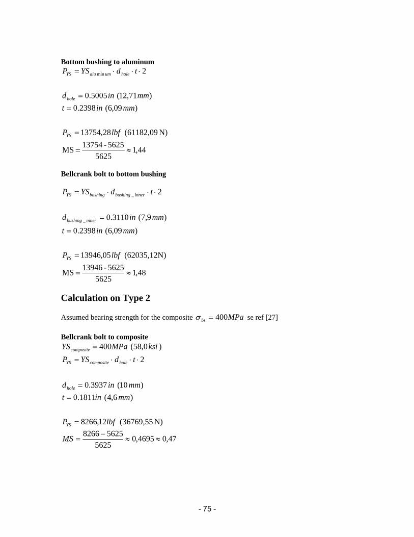
- 75 -
Bottom bushing to aluminum
44,15625
5625-13754MS
N)61182,09(28,13754
)09,6(2398.0)71,12(5005.0
2min
≈=
=
==
⋅⋅⋅=
lbfP
mmintmmind
tdYSP
YS
hole
holeumaluYS
Bellcrank bolt to bottom bushing
48,15625
5625-13946MS
62035,12N)(05,13946
)09,6(2398.0
)9,7(3110.0
2
_
_
≈=
=
=
=
⋅⋅⋅=
lbfP
mmint
mmind
tdYSP
YS
innerbushing
innerbushingbushingYS
Calculation on Type 2 Assumed bearing strength for the composite MPabs 400=σ se ref [27] Bellcrank bolt to composite
)58,0(400 ksiMPaYScomposite =
N)36769,55(12,8266
)6,4(1811.0)10(3937.0
2
lbfP
mmintmmind
tdYSP
YS
hole
holecompositeYS
=
==
⋅⋅⋅=
47,04695,05625
56258266≈≈
−=MS

- 76 -
Bottom bushing to composite
N)40789,7911(92,9169
)1,5(20079,0)10(3937.0
2
lbfP
mmintmmind
tdYSP
YS
hole
compositeYS
=
==
⋅⋅⋅=
63,0630,05625
56259170≈≈
−=MS
Bellcrank bolt to bottom bushing Here is the actuator bush calculated, since it has the smallest grip (t)
[ ]
85,08547,05625
5625-10433MS
N)46407,41(81,10432
)6(2362.0)6(2362.0
21:;5,932
_
_
≈≈=
=
=
=
=
⋅⋅⋅=
lbfP
mmint
mmind
refksiYS
tdYSP
YS
bushing
bushingbottom
bushingbottomYS
No calculations of the bending or shear in the bellcrank bolt has been made in type 2

- 77 -
M
F
F
A
A
e
Figure R. Unison ring seen from the side
mF
mF
APPENDIX Q, Stress calculation for the unison ring From ANSYS could the maximum moment force and tension force for an element be given, see below.
ineuplayinA
uplayinA
943898,0)2(119764,0
)1(133071,02
2
21
=−=
−=
Lay-up 1 Stall load
lbfFinlbfM
17763644
=⋅=
NOP load
lbfFinlbfM
3841195
=⋅=
Lay-up 2 Stall load
lbfFinlbfM
17633294
=⋅=
NOP load
lbfFinlbfM
3881149
=⋅=
Lay.up 1: )5,36(3,55,5337
133071,0943898,021195
133071,02384: max MPaksipsiNOP ≈≈
⋅⋅+
⋅=σ
AeM
AF
AeM
tensionasexspressedA
F
bendingtension
bending
tension
bendingtension
22
2
2
max
_
max
+=
⋅=⇒
⇒
=
+=
σ
σ
σ
σ
σσσ
Lay.up 2:
)2,146(2,2187,21178133071,0943898,02
3644133071,02
1776: max MPaksipsiStall ≈≈⋅⋅
+⋅
=σ
)0,151(9,2173,21929119764,0943898,02
32941119764,021763:
)2,46(7,6899,6701119764,0943898,02
1149119764,02388:
max
max
MPaksipsiStall
MPaksipsiNOP
≈≈⋅⋅
+⋅
=
≈≈⋅⋅
+⋅
=
σ
σ