2010 chile earthquake implications to the seismic …
TRANSCRIPT
2010 CHILE EARTHQUAKE IMPLICATIONS TO THE SEISMIC DESIGN OF BRIDGES
Genda Chen1, Phillip W. Yen2, Ian Buckle3, Tony Allen4,
Daniel Alzamora5, Jeffrey Ger6, and Juan G. Arias7
Abstract
In this paper, several critical issues based on field observed bridge performance are discussed and illustrated using example bridges. They include (1) the damaging potential of subduction-type ground motions that have multiple pulses, long duration, and possible rotational components; (2) the role of transverse diaphragms and their possible elimination for accelerated bridge construction; (3) the tsunami effects; (4) the effects of the number of joints and joint detail; and (5) the consequences of liquefaction-induced lateral movement and settlement. The implications of these issues to the seismic design of bridges are summarized in terms of ground motion provisions, load combinations, accelerated bridge constructions, load paths and bridge redundancies, and site remediations. Introduction
The M8.8 offshore Maule earthquake occurred on February 27, 2010, at 3:34 a.m. local time on a thrust fault at the boundary between the Nazca and South American tectonic plates [USGS, 2010]. The Nazca plate moved down and landward below the South American plate in the subduction zone, resulting in a sudden release of energy accumulated over time. The earthquake epicenter, located at Offshore Maule S35.909 and W72.733, was approximately 335 km SW of Santiago, 105 km NE of Concepcion, and 115 km WSW of Talca, Chile. The depth of the earthquake hypocenter was 35 km. The M8.8 event is the fifth largest earthquake recorded in modern times, followed by 21 aftershocks of magnitude 6.0 or greater by April 26, 2010.
The Chilean geological condition in the Maule region is eerily similar to that in the
1 Professor, Dept. of Civil, Architectural, and Environmental Engineering, Missouri University of Science and Technology, Rolla 2 Research Structural Engineer, Office of Infrastructure R&D, Turner-FairBank Highway Research Center, Federal Highway Administration, McLean 3 Professor, Dept. of Civil and Environmental Engineering, University of Nevada, Reno 4 State Geotechnical Engineer, State Materials Laboratory, Washington State Department of Transportation, Olympia 5 Geotechnical Engineer, Resource Center, Federal Highway Administration, Lakewood 6 Division Bridge Engineer, Florida Division, Federal Highway Administration, Tallahassee 7 Ph.D. Candidate, Dept. of Civil and Environmental Engineering, University of Nevada, Reno
215
Northwestern United States such as the states of Washington and Oregon. Many bridges that experienced damage during the 2010 Maule earthquake were designed and constructed following similar practices to what is stipulated by the U.S. seismic codes. Due to the similarities in earthquake environments, bridge design specifications, and construction processes, the observations and findings of bridge performance during the Maule earthquake provided valuable data sets and insights to both the improvement of current bridge design provisions and to the advancement of earthquake engineering.
Critical Issues Observed during the Post-Earthquake Reconnaissance
The February 27, 2010, Chile earthquake and associated tsunami(s) damaged about 200 bridges, including 20 that collapsed. This earthquake provided a unique opportunity to address several bridge design related issues, including (1) the damaging potential of subduction-type ground motions that have multiple pulses, long duration, and possible rotational components; (2) the tsunami effects; (3) the role of transverse diaphragms and their possible elimination for accelerated bridge construction; (4) the effects of the number of joints and joint detail; and (5) the consequences of liquefaction-induced lateral movement and settlement. The following sections will discuss in detail each of these critical issues using example bridges.
Subduction-Type Ground Motions
The 2010 Chile earthquake generated ground motions with long duration and multiple pulses [Boroschek et al., 2010]. In addition, the earthquake may also have induced significant rotational motions that can be inferred from the patterns of in-plane rotations of bridge superstructures. Fig. 1 shows the 32 bridge sites that were visited by the Federal Highway Administration (FHWA) reconnaissance team and highlights in red 7 of them with significant rotations in bridge superstructures. Located near Santiago, these seven sites are further away from the earthquake epicenter than Constitución and Concepción, but the bridges at these sites exclusively experienced significant rotations. A possible explanation for this observation is that, compared to Constitución and Concepción, the stiffer soil deposits near Santiago were favorable to the propagation and amplification of rotational motions during the Chile earthquake. The representative acceleration response spectra at the Hospital Station in Curicó are presented in Fig. 2 [Boroschek et al., 2010].
For the bridges with significant rotations, Table 1 lists the bridge name, bridge
orientation, skew angle, skew direction, material used in girder, presence of diaphragms, transverse displacement at intermediate bents, and direction of deck rotation. The combination of these parameters will help determine the mechanism of bridge deck rotations. Note that two parallel bridges were inspected at each of sites 1, 2, and 10. At sites 2 and 10, one bridge collapsed and the other bridge suffered minor damage. In Table 1, C denotes a clockwise rotation and C.C. represents a counter clockwise rotation.
216
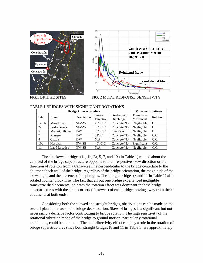
FIG.1 BRIDGE SITES FIG. 2 MODE RESPONSE SENSITIVITY TABLE 1 BRIDGES WITH SIGNIFICANT ROTATIONS
Bridge Characteristics Movement Pattern
Site Name Orientation Skew/ Direction
Girder/End Diaphragm
Transverse Movement
Rotation
1a,1b Miraflores NE-SW 20°/C.C. Concrete/No Negligible C. 2a Lo-Echevers NE-SW 33°/C.C. Concrete/No Negligible C. 5 Matta-Quilicura E-W 45°/C.C. Steel/Yes Negligible C. 7 Romero E-W 31°/C. Concrete/No Negligible C.C. 8 Chada E-W N.A. Concrete/No Negligible C.C. 10b Hospital NW-SE 40°/C.C. Concrete/No Significant C.C. 11 Las Mercedes NW-SE N.A. Concrete/No Negligible C.C.
The six skewed bridges (1a, 1b, 2a, 5, 7, and 10b in Table 1) rotated about the
centroid of the bridge superstructure opposite to their respective skew direction or the direction of rotation from a transverse line perpendicular to the bridge centerline to the abutment back wall of the bridge, regardless of the bridge orientation, the magnitude of the skew angle, and the presence of diaphragms. The straight bridges (8 and 11 in Table 1) also rotated counter clockwise. The fact that all but one bridge experienced negligible transverse displacements indicates the rotation effect was dominant in these bridge superstructures with the acute corners (if skewed) of each bridge moving away from their abutments at both ends.
Considering both the skewed and straight bridges, observations can be made on the
overall plausible reasons for bridge deck rotation. Skew of bridges is a significant but not necessarily a decisive factor contributing to bridge rotation. The high sensitivity of the rotational vibration mode of the bridge to ground motion, particularly rotational excitations, could be dominant. The fault directivity effect can play a role in the rotation of bridge superstructures since both straight bridges (8 and 11 in Table 1) are approximately
Constitución
Santiago
Concepción
Sites with Superstructure Rotations
Epicenter
217

oriented along the E-W direction. Based on the observations on skewed bridges, the movement of a bridge
superstructure can be illustrated in four steps as shown in Fig. 3. Under the earthquake excitations (1a, 1b, and possibly 3 in Fig. 3), the bridge superstructures first moved towards one abutment (left as shown in Fig. 3) and impacted against the abutment’s back wall (2 in Fig. 3). The reaction from the back wall then turned the superstructure in a direction opposite to the skew direction (counter clockwise in Fig. 3). The rotational motion (3 in Fig. 3) was amplified due to the fact that the rotational vibration mode of the bridge superstructure is more sensitive to the ground motions as illustrated in Fig. 2, since all the concrete girder bridges listed in Table 1 have superstructures supported on neoprene pads and restrained with vertical seismic bars. The superstructures are weakly restrained in the plan with the fundamental vibration mode in translation. With continuing deck rotations, the acute corners at two ends of the bridge finally moved away from the abutments, knocking off the curtain walls and becoming unseated (4a and 4b in Fig. 3). Note that the possibility of having significant rotational ground motions at the bridge sites can further amplify the rotational motion (3 in Fig. 3).
FIG. 3 DECK ROTATION OF A REPRESENTATIVE TWO-SPAN BRIDGE
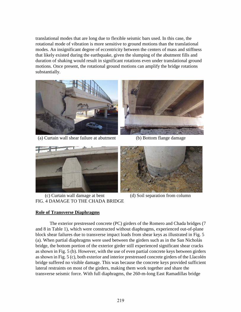
As an example, the 2-span Chada overpass as shown in Fig. 4 (a) is discussed in detail. The bridge superstructure was displaced significantly during the earthquake. The transverse offset between the deck and abutment seats ranged from 64 cm to 78 cm. The longitudinal gap between the end of girders and the abutment was up to 9 cm. The bottom flange and web of the exterior precast girder that hit the curtain walls at each abutment failed in shear as seen in Fig. 4 (a). The failure of the bottom flange is clearly seen in Fig. 4 (b). The two curtain walls at the intermediate bent were both damaged as shown in Fig. 4 (c). The bridge experienced strong shaking as indicated by the induced gap around columns, Fig. 4 (d). No structural damage was observed in the bridge columns.
When curtain walls at the intermediate bent and two abutments are not engaged, the in-plane motion of the bridge superstructure is governed by the mass of the superstructure, stiffness of seismic bars in round shape, and characteristics of ground motions. The period of the rotational mode of vibration is approximately 70% of the period of the two
218
translational modes that are long due to flexible seismic bars used. In this case, the rotational mode of vibration is more sensitive to ground motions than the translational modes. An insignificant degree of eccentricity between the centers of mass and stiffness that likely existed during the earthquake, given the slumping of the abutment fills and duration of shaking would result in significant rotations even under translational ground motions. Once present, the rotational ground motions can amplify the bridge rotations substantially.
(a) Curtain wall shear failure at abutment (b) Bottom flange damage
(c) Curtain wall damage at bent (d) Soil separation from column FIG. 4 DAMAGE TO THE CHADA BRIDGE Role of Transverse Diaphragms
The exterior prestressed concrete (PC) girders of the Romero and Chada bridges (7
and 8 in Table 1), which were constructed without diaphragms, experienced out-of-plane block shear failures due to transverse impact loads from shear keys as illustrated in Fig. 5 (a). When partial diaphragms were used between the girders such as in the San Nicholás bridge, the bottom portion of the exterior girder still experienced significant shear cracks as shown in Fig. 5 (b). However, with the use of even partial concrete keys between girders as shown in Fig. 5 (c), both exterior and interior prestressed concrete girders of the Llacolén bridge suffered no visible damage. This was because the concrete keys provided sufficient lateral restraints on most of the girders, making them work together and share the transverse seismic force. With full diaphragms, the 260-m-long East Ramadillas bridge
219
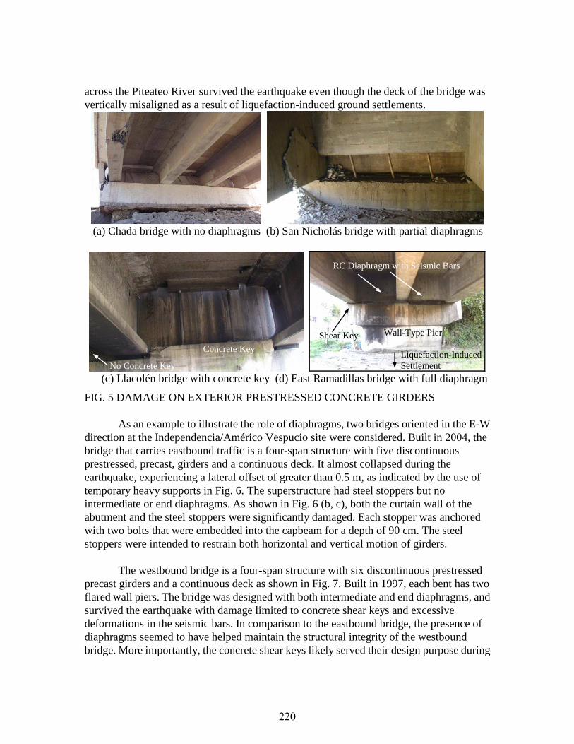
across the Piteateo River survived the earthquake even though the deck of the bridge was vertically misaligned as a result of liquefaction-induced ground settlements.
(a) Chada bridge with no diaphragms (b) San Nicholás bridge with partial diaphragms
(c) Llacolén bridge with concrete key (d) East Ramadillas bridge with full diaphragm
FIG. 5 DAMAGE ON EXTERIOR PRESTRESSED CONCRETE GIRDERS As an example to illustrate the role of diaphragms, two bridges oriented in the E-W
direction at the Independencia/Américo Vespucio site were considered. Built in 2004, the bridge that carries eastbound traffic is a four-span structure with five discontinuous prestressed, precast, girders and a continuous deck. It almost collapsed during the earthquake, experiencing a lateral offset of greater than 0.5 m, as indicated by the use of temporary heavy supports in Fig. 6. The superstructure had steel stoppers but no intermediate or end diaphragms. As shown in Fig. 6 (b, c), both the curtain wall of the abutment and the steel stoppers were significantly damaged. Each stopper was anchored with two bolts that were embedded into the capbeam for a depth of 90 cm. The steel stoppers were intended to restrain both horizontal and vertical motion of girders.
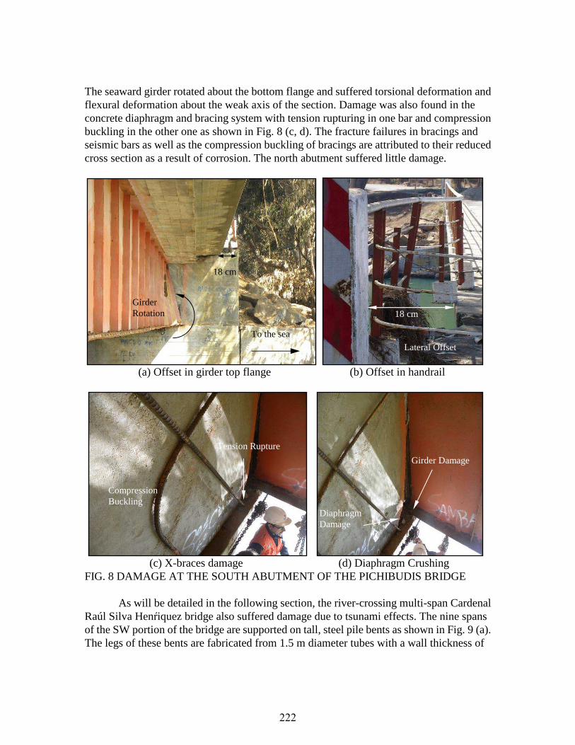
The westbound bridge is a four-span structure with six discontinuous prestressed
precast girders and a continuous deck as shown in Fig. 7. Built in 1997, each bent has two flared wall piers. The bridge was designed with both intermediate and end diaphragms, and survived the earthquake with damage limited to concrete shear keys and excessive deformations in the seismic bars. In comparison to the eastbound bridge, the presence of diaphragms seemed to have helped maintain the structural integrity of the westbound bridge. More importantly, the concrete shear keys likely served their design purpose during
RC Diaphragm with Seismic Bars
Wall-Type Pier Shear Key
Liquefaction-Induced Settlement
Concrete Key
No Concrete Key
220
the earthquake as opposed to the steel stoppers in the eastbound bridge. For both structures, no visible foundation damage was observed.
(a) Overall damage (b) Curtain wall at the west abutment (c) Damage to steel stoppers FIG. 6 DAMAGE TO THE EASTBOUND INDEPENDENCIA BRIDGE
(a) Displaced seismic bar (b) Typical flared wall pier (c) Damage of shear keys FIG. 7 DAMAGE TO THE WESTBOUND INDEPENDENCIA BRIDGE Tsunami Effects
The 2010 Chile earthquake induced significant tsunami effects on bridges along the
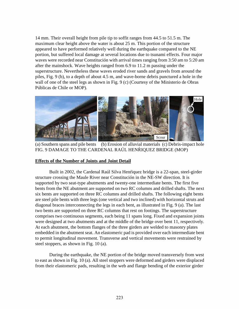
coast roads or across the rivers leading to the sea. Two bridges were inspected in detail for combined earthquake and tsunami effects. The Pichibudis bridge is located on the coast road (Route J-60) in Punta Duao near Iloca, and crosses a stream 300 m before it flows into the sea. This single span bridge has a total length of approximately 30 m. The superstructure is composed of two parallel 160 cm tall, plate girders and a reinforced concrete (RC) deck slab. The girders are detailed with cross frames and stiffeners, evenly spaced along the span and built with two end RC diaphragms and concentric braces fabricated from steel reinforcing bars, anchoring the superstructure into its seat-type abutments. The bottom flange of each girder sits on rubber pads at each abutment.
The tsunami at the City of Iloca was characterized by three sea waves that arrived
every 25 minutes on the average, starting approximately 4:00 am. Since the clear height of the bridge from the water level was about 1.5 m, the tsunami waves passed over the bridge inducing large lateral forces on the girders. At the south abutment, the bridge deck experienced a permanent lateral displacement of about 18 cm, as indicated in Fig. 8 (a, b).
Seismic Bars
221
The seaward girder rotated about the bottom flange and suffered torsional deformation and flexural deformation about the weak axis of the section. Damage was also found in the concrete diaphragm and bracing system with tension rupturing in one bar and compression buckling in the other one as shown in Fig. 8 (c, d). The fracture failures in bracings and seismic bars as well as the compression buckling of bracings are attributed to their reduced cross section as a result of corrosion. The north abutment suffered little damage.
(a) Offset in girder top flange (b) Offset in handrail
(c) X-braces damage (d) Diaphragm Crushing FIG. 8 DAMAGE AT THE SOUTH ABUTMENT OF THE PICHIBUDIS BRIDGE
As will be detailed in the following section, the river-crossing multi-span Cardenal
Raúl Silva Henŕiquez bridge also suffered damage due to tsunami effects. The nine spans of the SW portion of the bridge are supported on tall, steel pile bents as shown in Fig. 9 (a). The legs of these bents are fabricated from 1.5 m diameter tubes with a wall thickness of
Girder Damage
Diaphragm Damage
18 cm
Lateral Offset
Girder Rotation
18 cm
To the sea
Tension Rupture
Compression Buckling
222
14 mm. Their overall height from pile tip to soffit ranges from 44.5 to 51.5 m. The maximum clear height above the water is about 25 m. This portion of the structure appeared to have performed relatively well during the earthquake compared to the NE portion, but suffered local damage at several locations due to tsunami effects. Four major waves were recorded near Constitución with arrival times ranging from 3:50 am to 5:20 am after the mainshock. Wave heights ranged from 6.9 to 11.2 m passing under the superstructure. Nevertheless these waves eroded river sands and gravels from around the piles, Fig. 9 (b), to a depth of about 4.5 m, and wave-borne debris punctured a hole in the wall of one of the steel legs as shown in Fig. 9 (c) (Courtesy of the Ministerio de Obras Públicas de Chile or MOP).
(a) Southern spans and pile bents (b) Erosion of alluvial materials (c) Debris-impact hole FIG. 9 DAMAGE TO THE CARDENAL RAÚL HENŔIQUEZ BRIDGE (MOP) Effects of the Number of Joints and Joint Detail
Built in 2002, the Cardenal Raúl Silva Henŕiquez bridge is a 22-span, steel-girder structure crossing the Maule River near Constitución in the NE-SW direction. It is supported by two seat-type abutments and twenty-one intermediate bents. The first five bents from the NE abutment are supported on two RC columns and drilled shafts. The next six bents are supported on three RC columns and drilled shafts. The following eight bents are steel pile bents with three legs (one vertical and two inclined) with horizontal struts and diagonal braces interconnecting the legs in each bent, as illustrated in Fig. 9 (a). The last two bents are supported on three RC columns that rest on footings. The superstructure comprises two continuous segments, each being 11 spans long. Fixed and expansion joints were designed at two abutments and at the middle of the bridge over bent 11, respectively. At each abutment, the bottom flanges of the three girders are welded to masonry plates embedded in the abutment seat. An elastomeric pad is provided over each intermediate bent to permit longitudinal movement. Transverse and vertical movements were restrained by steel stoppers, as shown in Fig. 10 (a).
During the earthquake, the NE portion of the bridge moved transversely from west to east as shown in Fig. 10 (a). All steel stoppers were deformed and girders were displaced from their elastomeric pads, resulting in the web and flange bending of the exterior girder
Hole
Scour
223

about its weak axis at the NE abutment, as shown in Fig. 10 (d). The transverse diaphragms at the intermediate bents and abutments buckled as shown in Fig. 10 (a, c). At the NE abutment, the webs and bottom flanges were fractured in all three steel girders, and both bearing stiffener and web buckled as shown in Fig. 10 (b). This type of damage is indicative of large longitudinal loads in the superstructure being attracted to the fixed bearing at the abutment. The weld detail at the abutment transferred the longitudinal loads into a significant bending moment, locally causing stress concentrations in the steel girders at the end of their supporting masonry plates. Note that the weld between the girders and the masonry plate did not fail. As shown in Fig. 10 (d), due to severe damage in the web and flange of girders, a steel beam was used to temporarily transfer loads from the flange to the abutment seat bypassing the web of the girders.
(a) Girder offset and cross frame buckling (b) Girder damage at north abutment
(c) Crossframe buckling (d) Temporary repair at NE abutment FIG. 10 SUPERSTRUCTURE DAMAGE AT THE NE PORTION
Buckling of end diaphragm
Buckling of End Diaphragm
224
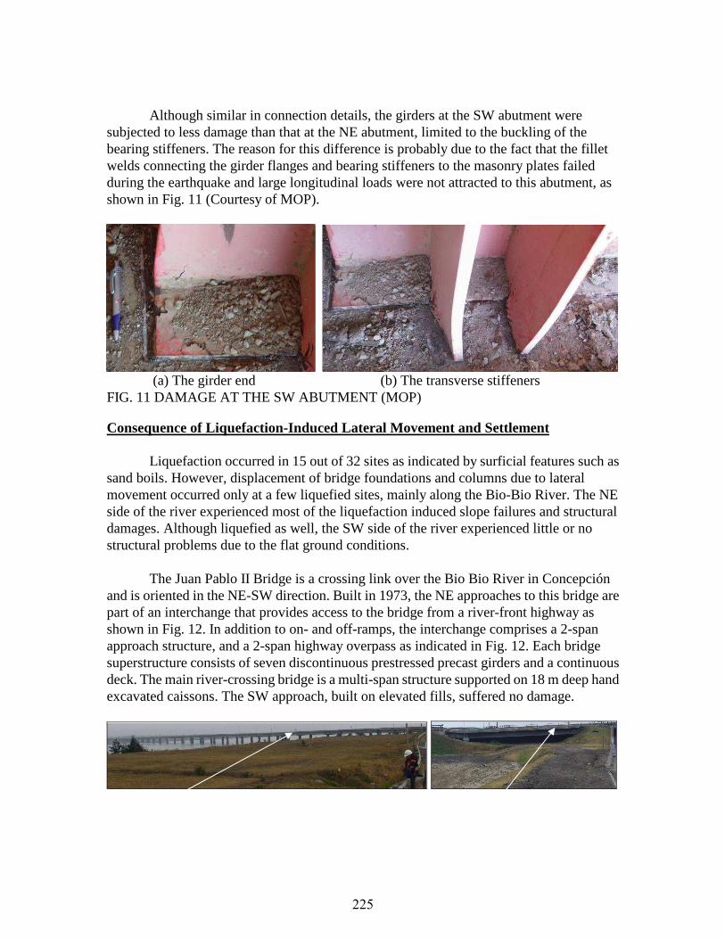
Although similar in connection details, the girders at the SW abutment were subjected to less damage than that at the NE abutment, limited to the buckling of the bearing stiffeners. The reason for this difference is probably due to the fact that the fillet welds connecting the girder flanges and bearing stiffeners to the masonry plates failed during the earthquake and large longitudinal loads were not attracted to this abutment, as shown in Fig. 11 (Courtesy of MOP).
(a) The girder end (b) The transverse stiffeners FIG. 11 DAMAGE AT THE SW ABUTMENT (MOP) Consequence of Liquefaction-Induced Lateral Movement and Settlement
Liquefaction occurred in 15 out of 32 sites as indicated by surficial features such as sand boils. However, displacement of bridge foundations and columns due to lateral movement occurred only at a few liquefied sites, mainly along the Bio-Bio River. The NE side of the river experienced most of the liquefaction induced slope failures and structural damages. Although liquefied as well, the SW side of the river experienced little or no structural problems due to the flat ground conditions.
The Juan Pablo II Bridge is a crossing link over the Bio Bio River in Concepción
and is oriented in the NE-SW direction. Built in 1973, the NE approaches to this bridge are part of an interchange that provides access to the bridge from a river-front highway as shown in Fig. 12. In addition to on- and off-ramps, the interchange comprises a 2-span approach structure, and a 2-span highway overpass as indicated in Fig. 12. Each bridge superstructure consists of seven discontinuous prestressed precast girders and a continuous deck. The main river-crossing bridge is a multi-span structure supported on 18 m deep hand excavated caissons. The SW approach, built on elevated fills, suffered no damage.
225
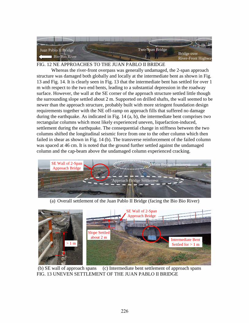
FIG. 12 NE APPROACHES TO THE JUAN PABLO II BRIDGE
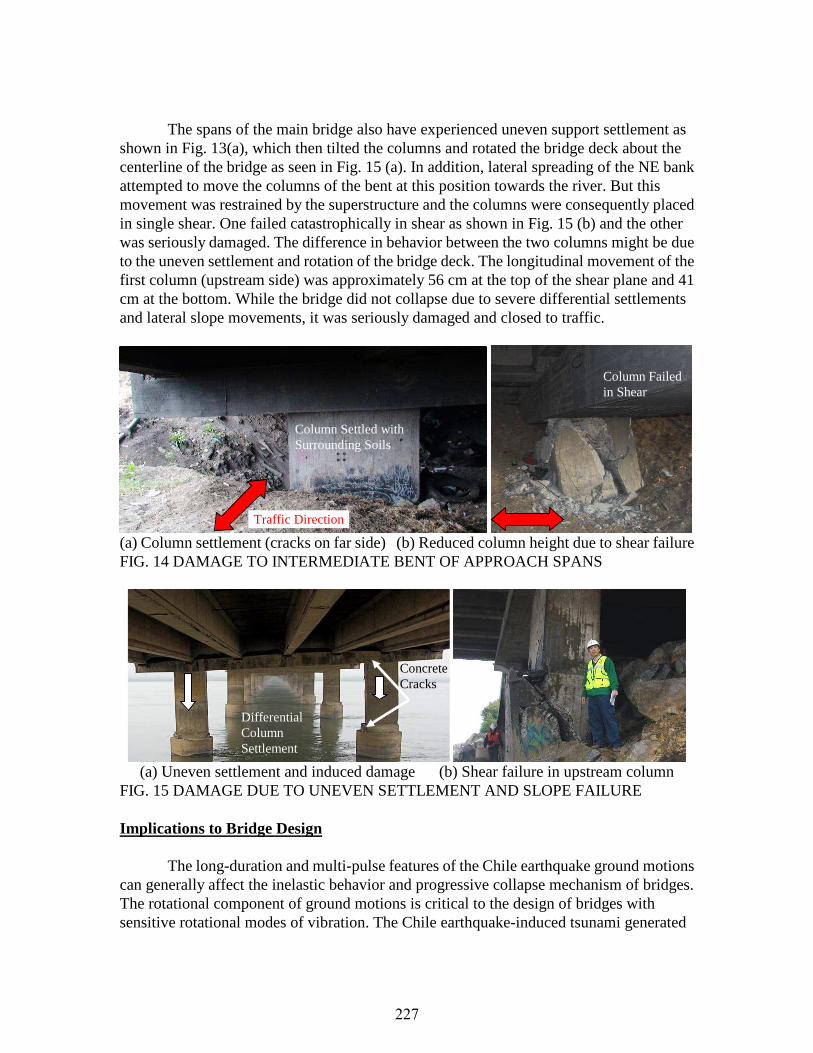
Whereas the river-front overpass was generally undamaged, the 2-span approach structure was damaged both globally and locally at the intermediate bent as shown in Fig. 13 and Fig. 14. It is clearly seen in Fig. 13 that the intermediate bent has settled for over 1 m with respect to the two end bents, leading to a substantial depression in the roadway surface. However, the wall at the SE corner of the approach structure settled little though the surrounding slope settled about 2 m. Supported on drilled shafts, the wall seemed to be newer than the approach structure, probably built with more stringent foundation design requirements together with the NE off-ramp on approach fills that suffered no damage during the earthquake. As indicated in Fig. 14 (a, b), the intermediate bent comprises two rectangular columns which most likely experienced uneven, liquefaction-induced, settlement during the earthquake. The consequential change in stiffness between the two columns shifted the longitudinal seismic force from one to the other column which then failed in shear as shown in Fig. 14 (b). The transverse reinforcement of the failed column was spaced at 46 cm. It is noted that the ground further settled against the undamaged column and the cap-beam above the undamaged column experienced cracking.
(a) Overall settlement of the Juan Pablo II Bridge (facing the Bio Bio River)
(b) SE wall of approach spans (c) Intermediate bent settlement of approach spans FIG. 13 UNEVEN SETTLEMENT OF THE JUAN PABLO II BRIDGE
Bio Bio River Bridge over River-Front Highway
Two-Span Bridge Juan Pablo II Bridge
SE Wall of 2-Span Approach Bridge
SE Wall of 2-Span Approach Bridge
> 1 m
Slope Settled about 2 m Intermediate Bent
Settled for > 1 m
Approach Bridge Settlement
Main Bridge Settlement
226
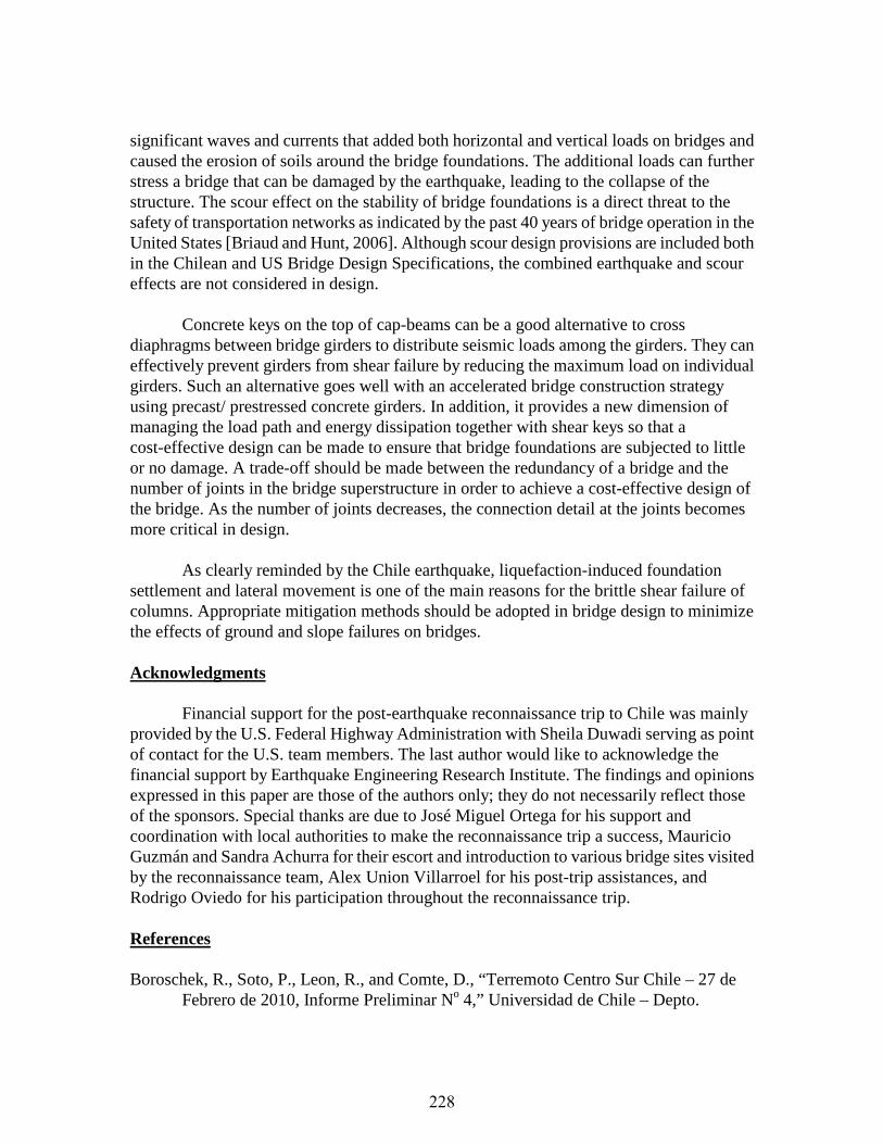
The spans of the main bridge also have experienced uneven support settlement as shown in Fig. 13(a), which then tilted the columns and rotated the bridge deck about the centerline of the bridge as seen in Fig. 15 (a). In addition, lateral spreading of the NE bank attempted to move the columns of the bent at this position towards the river. But this movement was restrained by the superstructure and the columns were consequently placed in single shear. One failed catastrophically in shear as shown in Fig. 15 (b) and the other was seriously damaged. The difference in behavior between the two columns might be due to the uneven settlement and rotation of the bridge deck. The longitudinal movement of the first column (upstream side) was approximately 56 cm at the top of the shear plane and 41 cm at the bottom. While the bridge did not collapse due to severe differential settlements and lateral slope movements, it was seriously damaged and closed to traffic.
(a) Column settlement (cracks on far side) (b) Reduced column height due to shear failure FIG. 14 DAMAGE TO INTERMEDIATE BENT OF APPROACH SPANS
(a) Uneven settlement and induced damage (b) Shear failure in upstream column
FIG. 15 DAMAGE DUE TO UNEVEN SETTLEMENT AND SLOPE FAILURE
Implications to Bridge Design The long-duration and multi-pulse features of the Chile earthquake ground motions
can generally affect the inelastic behavior and progressive collapse mechanism of bridges. The rotational component of ground motions is critical to the design of bridges with sensitive rotational modes of vibration. The Chile earthquake-induced tsunami generated
Column Settled with Surrounding Soils
Column Failed in Shear
Differential Column Settlement
Concrete Cracks
Traffic Direction
227
significant waves and currents that added both horizontal and vertical loads on bridges and caused the erosion of soils around the bridge foundations. The additional loads can further stress a bridge that can be damaged by the earthquake, leading to the collapse of the structure. The scour effect on the stability of bridge foundations is a direct threat to the safety of transportation networks as indicated by the past 40 years of bridge operation in the United States [Briaud and Hunt, 2006]. Although scour design provisions are included both in the Chilean and US Bridge Design Specifications, the combined earthquake and scour effects are not considered in design.
Concrete keys on the top of cap-beams can be a good alternative to cross
diaphragms between bridge girders to distribute seismic loads among the girders. They can effectively prevent girders from shear failure by reducing the maximum load on individual girders. Such an alternative goes well with an accelerated bridge construction strategy using precast/ prestressed concrete girders. In addition, it provides a new dimension of managing the load path and energy dissipation together with shear keys so that a cost-effective design can be made to ensure that bridge foundations are subjected to little or no damage. A trade-off should be made between the redundancy of a bridge and the number of joints in the bridge superstructure in order to achieve a cost-effective design of the bridge. As the number of joints decreases, the connection detail at the joints becomes more critical in design.
As clearly reminded by the Chile earthquake, liquefaction-induced foundation
settlement and lateral movement is one of the main reasons for the brittle shear failure of columns. Appropriate mitigation methods should be adopted in bridge design to minimize the effects of ground and slope failures on bridges.
Acknowledgments
Financial support for the post-earthquake reconnaissance trip to Chile was mainly provided by the U.S. Federal Highway Administration with Sheila Duwadi serving as point of contact for the U.S. team members. The last author would like to acknowledge the financial support by Earthquake Engineering Research Institute. The findings and opinions expressed in this paper are those of the authors only; they do not necessarily reflect those of the sponsors. Special thanks are due to José Miguel Ortega for his support and coordination with local authorities to make the reconnaissance trip a success, Mauricio Guzmán and Sandra Achurra for their escort and introduction to various bridge sites visited by the reconnaissance team, Alex Union Villarroel for his post-trip assistances, and Rodrigo Oviedo for his participation throughout the reconnaissance trip. References
Boroschek, R., Soto, P., Leon, R., and Comte, D., “Terremoto Centro Sur Chile – 27 de
Febrero de 2010, Informe Preliminar No 4,” Universidad de Chile – Depto.
228

Ingenieria Civil, and Depto. De Geofisica, 2010, 29 pp. Briaud, J. L., and Hunt, B. E., “Bridge Scour & the Structural Engineer,” Structures
Magazine, December 2006, pp.58-61. USGS, Magnitude 8.8 - Offshore Maule, Chile, February 27, 2010,
http://earthquake.usgs.gov/earthquakes/eqinthenews/2010/us2010tfan/, United States Geological Survey (USGS) Earthquake Hazards Program, 2010.
229