2016 bearcats baja rear suspension
TRANSCRIPT

2016 BEARCATS BAJA
REAR SUSPENSION
A Baccalaureate thesis submitted to the
Department of Mechanical and Materials Engineering College of Engineering and Applied Science
University of Cincinnati
in partial fulfillment of the requirements for the degree of
Bachelor of Science
in Mechanical Engineering Technology
by
Luis Miguel Gonzalez
April 2016
Thesis Advisor:
Professor Allen Arthur

TABLE OF CONTENTS
TABLE OF CONTENTS .......................................................................................................... 2
LIST OF FIGURES ............................................. ERROR! BOOKMARK NOT DEFINED.
ABSTRACT .............................................................................................................................. 3
INTRODUCTION .................................................................................................................... 3
REAR SUSPENSION SYSTEM DESIGN .............................................................................. 4
PROBLEM STATEMENT ................................................................................................................................ 4 RESEARCH SUMMARY ................................................................................................................................. 4 MAIN DESIGN GOALS ................................................................................................................................... 4 DESIGN SPECIFICATIONS ............................................................................................................................ 5 FINITE ELEMENT ANALYSIS ....................................................................................................................... 7 DESIGN FABRICATION: ................................................................................................................................ 9
CONCLUSION ....................................................................................................................... 12
ACKNOWLEDGEMENTS .................................................................................................... 12
WORKS CITED ..................................................................................................................... 13
APPENDIX A: DEFINITIONS AND ABBREVIATIONS ................................................... 13
APPENDIX B: TECH INSPECTION REQUIREMENTS .................................................... 14
APPENDIX C: RESEARCH .................................................................................................. 15
APPENDIX D: BUDGET....................................................................................................... 17
APPENDIX E: SCHEDULE .................................................................................................. 18
APPENDIX F: WEIGHT ANALYSIS ................................................................................... 18
APPENDIX G: DRAWINGS ................................................................................................. 19

ABSTRACT
It was the initial intent of the University of Cincinnati Baja team to design a car from the
ground up and compete in the 2016 Baja SAE design competition. Unfortunately, due to
inadequate project management from the team as a whole, we were unable to register in time
to compete in the international competitions held this year. This thesis will explain in detail
the major phases of researching, designing, and fabricating the rear suspension on the 2016
Baja Car.
INTRODUCTION
Baja SAE is an annual competition hosted by the Society of Automotive Engineers (SAE)
that promotes intercollegiate competition through off-road races and events. Many
Universities from around the world go through the process of designing and building small
off-road vehicles. The proposition of this competition is to push these vehicles in a barrage of
off road events in the hopes that the car will endure the abuse and ultimately win. Events
during the competition will commence throughout the day and will eventually lead up to a
four hour endurance race at the end. These vehicles need to be designed to be structurally
sound, dynamic, and cost effective. The only similarities between the competing vehicles are
the Briggs and Stratton engines that propel them. This places all of the emphasis on each sub-
system design. The implication is that each sub-system must work together efficiently as a
cohesive unit in order to ensure the best possible performance from the vehicle.
Each year when designing a new car, the subsystems will be broken down into teams. The
rear suspension team is responsible for all suspension components from the middle of the car
to the rear. This sub-system plays a vital part in the overall handling, speed, endurance, and
braking of the vehicle. The rear suspension will affect how well the car performs over
obstacles and how responsive it is to the driver. Furthermore the rear suspension team works
closely with the frame and drivetrain teams to ensure all aspects are taken into consideration
and the car can be assembled properly. During actual competition, there is an evaluation by
representatives of SAE to thoroughly judge the comprehensive design of the vehicle. Since
we will not be going to competition this year, it has been agreed to have a formal technical
inspection hosted by Associate Dean of Undergraduate Affairs Allen Arthur. This technical
inspection serves as an alternative way to prove that the rear suspension design meets all
requirements for the SAE International Baja rules and could function during competition.

REAR SUSPENSION SYSTEM DESIGN
PROBLEM STATEMENT
The Rear Suspension sub-system for the 2016 Baja car can be improved by focusing on
improving handling, reliability, and making the system more dynamic. The overall goal of
the rear suspension team is to design a system better than that of previous years. This system
will provide a solid foundation to the rear of the car by supporting it through all terrain; with
an emphasis on obstacles.
RESEARCH SUMMARY
Originally the idea was to incorporate a double wishbone A- arm style design in order to
make the rear suspension stronger and more reliable. However, it was later decided to switch
to a trailing arm design. This set-up better allows the rear suspension team to meet our goals.
MAIN DESIGN GOALS
The fundamental first design goals:
Improve handling
Reduce collective weight of the system
Make maintenance less cumbersome
Reduce the overall cost
To start, the first goal was to improve the handling of the vehicle especially with flexibly
articulating over obstacles. The Baja SAE competition’s maneuverability event is formed to
assess a vehicle’s handling ability over a standard Baja terrain (4). This event may have
hazards such as ruts, rocks, drop-offs, or logs. The concept behind free standing trailing arms
is that they will provide the wheel travel and independent motion needed in order to
confidently take on obstacles. They also will not stag roots and branches much like A-arms
would. It has also been noted through competition that an A-arm suspension was susceptible
to drive axle disengagement if a member was to fail.
The rear suspension will account for approximately 25% of the total vehicle weight.
Regarding the reduction of weight, the trailing arm design was determined to be the best
choice. The goal weight for the rear suspension design was decided to be 60 lbs. Because this
system was going to be designed as a stand-alone trailing arm system, there were not any
lateral linkages. Therefore, this meant that there were a lower number of total components in
the rear suspension which lead to savings in weight. Another option that was employed was
to design new bearing carriers made from 6061 Aluminum rather than using the cast Polaris
Bearing carriers. Lastly, Fox Air Shocks will be used on this design. They will provide a
necessary adjustability but will cut down on weight due to the absence of a steel spring or

coil.
When considering the design of the suspension on the 2016 UC Baja car one thing always
sticks out; that is the topic of maintenance. No matter how durable you make a competition
car there always seems to be things that need adjustment or mending. This occurs because the
team is constantly pushing the car to limit in each event. When things do break, they need to
be easy to mend or replace to insure that we get the maximum use of the car’s capabilities in
all events. Due to the nature of SAE Baja and automotive sports in general, there are many
adjustments and servicing will have to be done on the vehicle. It is also very possible that a
lot of the work done to the car will be done out of the shop, in the pits, or even in the field.
This makes ease of maintenance imperative to the design of the rear suspension. This
suspension needs to be easy to work on and easy to service during competition. The rear
suspension design must also refrain from being too cumbersome to work around when
service is required to the gearbox, engine or frame. The elimination of lateral linkages allow
for effortless access to the vital systems located in the rear of the car.
In regards to cost of the rear suspension design, the decision was made to set a maximum
budget of $2,000. This was concluded after finding the reported budgets of the 2013 Baja
rear suspension ($1,939) and the 2014 Baja rear suspension ($1,954). There was an initial
push to try and obtain funding through sponsorships. Companies that were contacted about
possible sponsorships included Bilstein, Ransohoff and Fifth Third Bank. Unfortunately,
there was never a response from Bilstein or Fifth Third even after multiple attempts of trying
to contact them. Ransohoff was able to provide us adequate 4130 steel material to fabricate
the trailing arms and shock mounting tabs. Not having as many components also provided
the means to cut back on cost. Lastly, the frame material from the 2012 Baja car was
recycled and reused as material to construct trailing arms for the 2016 car. The 2016 rear
suspension total cost ended up coming to $1,181.
DESIGN SPECIFICATIONS
Vehicle Specifications:
Rear Track Width: 47”
Wheel Base: 63”
Camber Change Rate: 1.5° (+/-)
Static Camber: 0°
Static Toe: 0°
Firewall to Rear Axle: 21.1”
Ground Clearance (Rear): 11.2”
Vertical Wheel Travel: 9.8”
System Total Weight: 64.83 lbs

The rear suspension architecture on the 2016 vehicle is a true trailing arm design and does
not consist of lateral linkages. This design provides the most optimal way to meet the initial
goals set out. The finished track width exceeded the initial track width objective of 46 inches.
This track width was determined in order to accommodate the vehicle during events where
the course was narrow and tough to navigate. Even though the mark was missed by an inch,
it was accepted since the extra inch could have come from minor errors while building the
car. The wheelbase is comparable to UC Baja vehicles by being around 60 inches. Static
camber and toe were built and designed to be neutral. Having neutral camber and toe aids the
goal of improved obstacle handling. However, there is an overall camber change of 1.5° in
the positive and negative direction as the wheel travels. This value was found using a
magnetic compass fixed upon the wheel as the trailing arm was articulated up and down.
Figure 1: Selected Design Overview
The final rear suspension design was straight forward with only eight major components. The
wheels and tires used were similar to the set-up on the 2013 Baja car. They were comprised
of 6061 aluminum Douglas Blue Label wheels and 21” x 7”x 10” Kenda Klaw XC tires. This
combination was selected because of its prior success with previous UC Baja teams and this
allowed us to save money by reusing wheels and tires already found in the shop.
The spherical bearings and cups were from Pegasus Auto racing and were both made of high
strength 4130. The gas shocks that were selected were Fox Float 3 Factory Series. These
provided lower weight than coil-overs and adjustability through adding and withdrawing gas.
The Float 3’s had a total travel of 5.25 inches. They were also used in the front suspension
design. The wheel hubs and drive axles came from a Polaris Sportsman 300 much like past
Baja cars.
The components that were fabricated were the trailing arms and the bearing carriers. The
trailing arms were constructed with 4130 steel tubing from the left over frame of the 2012
Baja Car. The bearing carriers were machined from a 6 inch diameter 6061 aluminum
cylinder.

The final weight ended up exceeding the goal by 4.83 lbs. This was the result of using frame
tubing from the 2012 Baja car that was thicker than the material included in the 3D model.
More details will be explained in the Design Fabrication section.
Figure 2: Axle & Bearing Carrier View
FINITE ELEMENT ANALYSIS
Primary Assumptions:
Vehicle Weight (+ Driver): 600 lbs
Vehicle Mass (+ Driver): 18.63 slugs
Top Speed: 30 mph (44 ft/s)
Friction Factor: 0.9 (rubber to asphalt)
Front of Wheel Impact –
Testing Parameters:
Mass: 18.63 slugs
Half Top Speed: 22 ft/s
Decel Distance: 0.42 ft
Average Speed: 11 ft/s
Decel time: 0.04 s
Acceleration: 580.8 ft/s^2
Force: 10,822.41 lbf
Spin Adjustment: 50% of total force
Adjusted Force: 5,411.2 lbf
Figure 3: Front of Wheel Impact
Bearing Carrier
- Max Force: 37 ksi
- Yield Strength: 45 ksi
- Factor of Safety: 1.2

Side of Wheel Impact –
Testing Parameters:
Mass: 18.63 slugs
Impact Speed: 10 ft/s
Decel Distance: 0.08 ft
Average Speed: 5 ft/s
Decel Time: 0.02 s
Acceleration: 600 ft/s^2
Force: 11180.12 lbf
Spin Adjustment: 25%
Adjusted Force: 2795 lbf
5,411.2 lbf
5,411.2 lbf
2795 lbf
Figure 4: Front of Wheel Impact
Trailing Arm
- Max Force: 55.5 ksi
- Yield Strength: 75 ksi
- Factor of Safety: 1.4
Figure 5: Side of Wheel Impact
Trailing Arm
- Max Force: 65.4 ksi
- Yield Strength: 75 ksi
- Factor of Safety: 1.2

Six Foot Drop (on one wheel) –
Testing Parameters:
Mass: 18.63 slugs
Impact Speed: 19.65 ft/s
Decel Distance: 1 ft
Average Speed: 9.825 ft/s
Decel Time: 0.108 s
Acceleration: 193.06 ft/s^2
Force: 3597.42 lbf
Wheel Offset: 1.6 in (0.133 ft)
Bearing Width: 0.795 in (0.0663 ft)
DESIGN FABRICATION:
All fabricated components for the 2016 rear suspension were built in house by the rear
suspension team. These parts were created by utilizing the Baja shop and machine shop in
OCAS on Victory Parkway as well as the machine shop at main campus.
The trailing arms were made of 4130 steel tubing. This tubing was recycled from the frame
of the 2012 Baja car that was no longer in use. Reusing material once again allowed us to
save on material cost. However the wall thickness of the tubing was .05 inch thicker than the
original model. The extra thickness solidified the FEA results but created a heavier trailing
3597 lbf
3597 lbf
Figure 6: Six Foot Drop
Bearing Carrier
- Max Force: 34 ksi
- Yield Strength: 45 ksi
- Factor of Safety: 1.3
Figure 7: Six Foot Drop
Trailing Arm
- Max Force: 46 ksi
- Yield Strength: 75 ksi
- Factor of Safety: 1.6
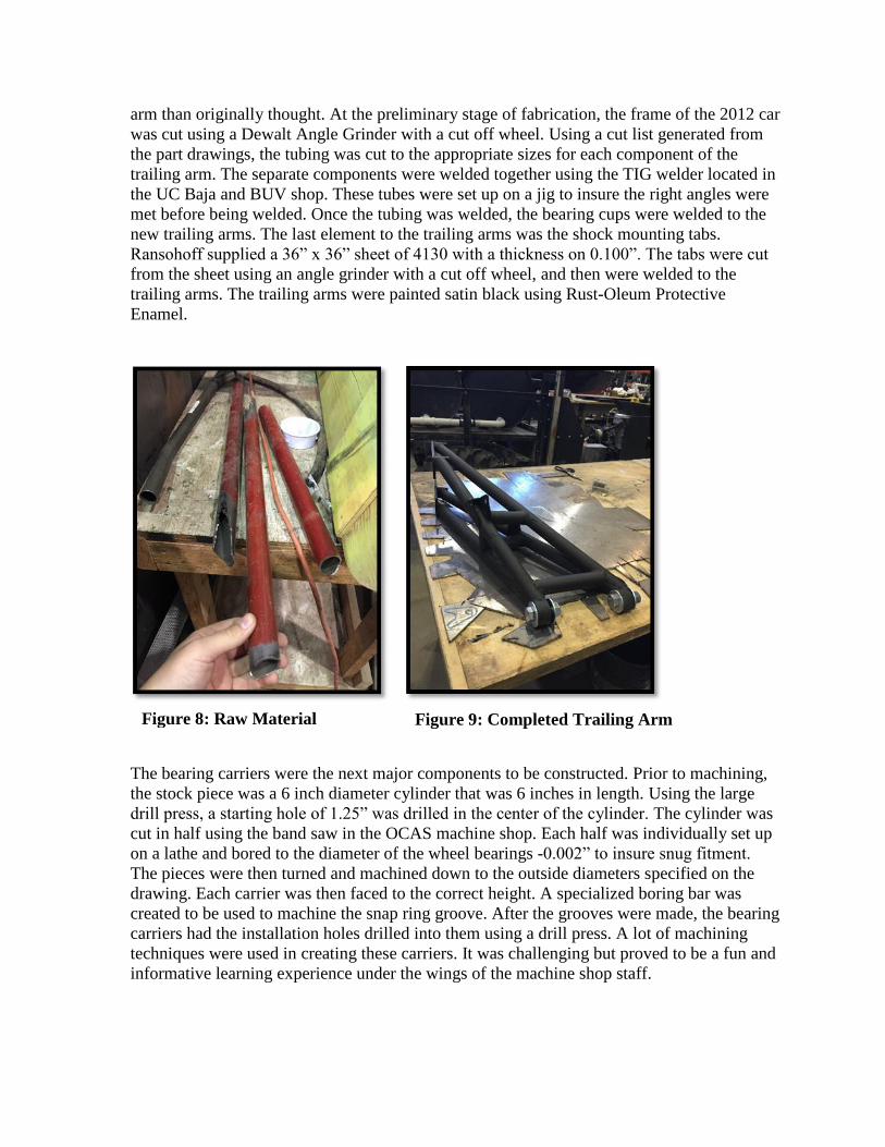
arm than originally thought. At the preliminary stage of fabrication, the frame of the 2012 car
was cut using a Dewalt Angle Grinder with a cut off wheel. Using a cut list generated from
the part drawings, the tubing was cut to the appropriate sizes for each component of the
trailing arm. The separate components were welded together using the TIG welder located in
the UC Baja and BUV shop. These tubes were set up on a jig to insure the right angles were
met before being welded. Once the tubing was welded, the bearing cups were welded to the
new trailing arms. The last element to the trailing arms was the shock mounting tabs.
Ransohoff supplied a 36” x 36” sheet of 4130 with a thickness on 0.100”. The tabs were cut
from the sheet using an angle grinder with a cut off wheel, and then were welded to the
trailing arms. The trailing arms were painted satin black using Rust-Oleum Protective
Enamel.
The bearing carriers were the next major components to be constructed. Prior to machining,
the stock piece was a 6 inch diameter cylinder that was 6 inches in length. Using the large
drill press, a starting hole of 1.25” was drilled in the center of the cylinder. The cylinder was
cut in half using the band saw in the OCAS machine shop. Each half was individually set up
on a lathe and bored to the diameter of the wheel bearings -0.002” to insure snug fitment.
The pieces were then turned and machined down to the outside diameters specified on the
drawing. Each carrier was then faced to the correct height. A specialized boring bar was
created to be used to machine the snap ring groove. After the grooves were made, the bearing
carriers had the installation holes drilled into them using a drill press. A lot of machining
techniques were used in creating these carriers. It was challenging but proved to be a fun and
informative learning experience under the wings of the machine shop staff.
Figure 8: Raw Material Figure 9: Completed Trailing Arm
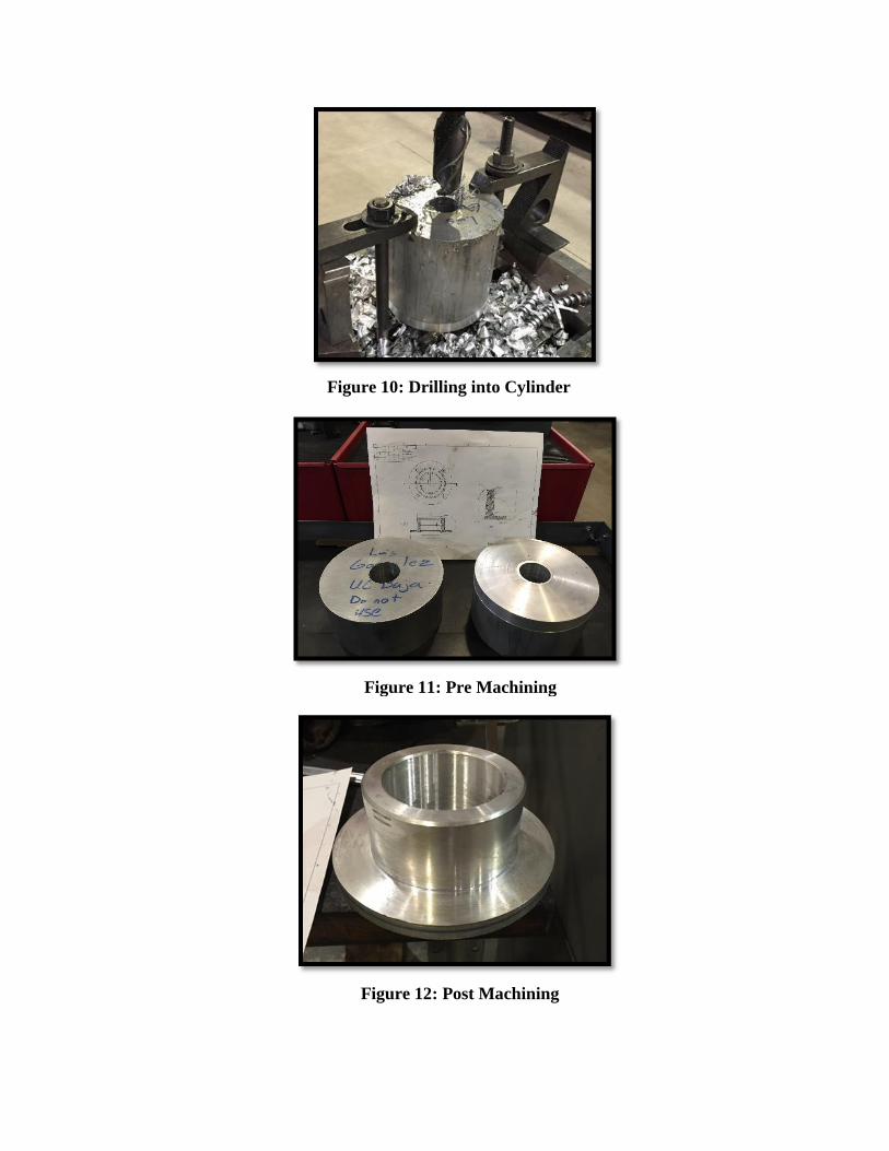
Figure 10: Drilling into Cylinder
Figure 12: Post Machining
Figure 11: Pre Machining
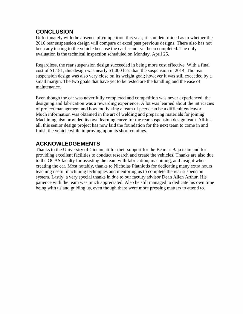
CONCLUSION Unfortunately with the absence of competition this year, it is undetermined as to whether the
2016 rear suspension design will compare or excel past previous designs. There also has not
been any testing to the vehicle because the car has not yet been completed. The only
evaluation is the technical inspection scheduled on Monday, April 25.
Regardless, the rear suspension design succeeded in being more cost effective. With a final
cost of $1,181, this design was nearly $1,000 less than the suspension in 2014. The rear
suspension design was also very close on its weight goal; however it was still exceeded by a
small margin. The two goals that have yet to be tested are the handling and the ease of
maintenance.
Even though the car was never fully completed and competition was never experienced, the
designing and fabrication was a rewarding experience. A lot was learned about the intricacies
of project management and how motivating a team of peers can be a difficult endeavor.
Much information was obtained in the art of welding and preparing materials for joining.
Machining also provided its own learning curve for the rear suspension design team. All-in-
all, this senior design project has now laid the foundation for the next team to come in and
finish the vehicle while improving upon its short comings.
ACKNOWLEDGEMENTS Thanks to the University of Cincinnati for their support for the Bearcat Baja team and for
providing excellent facilities to conduct research and create the vehicles. Thanks are also due
to the OCAS faculty for assisting the team with fabrication, machining, and insight when
creating the car. Most notably, thanks to Nicholas Platniotis for dedicating many extra hours
teaching useful machining techniques and mentoring us to complete the rear suspension
system. Lastly, a very special thanks in due to our faculty advisor Dean Allen Arthur. His
patience with the team was much appreciated. Also he still managed to dedicate his own time
being with us and guiding us, even though there were more pressing matters to attend to.

WORKS CITED 1. Reedy, Paul. Shocks Air vs. Coilover. BuggyNews. [Online] July 2013.
http://buggynews.com/shocks-air-vs-coilover-king-fox-foa-monroe-price-links-t44470.html.
2. Deits, Ron. MacPherson and Double Wishbone. [Online] December 2007.
http://www.clubwrx.net/forums/suspension-wheels/168479-macpherson-vs-double-
wishbone.html.
3. International, SAE. SAE Baja. [Online] April 2014.
http://students.sae.org/cds/bajasae/about.htm.
4. International, SAE. 2016 Baja Rules. [Online] February 2016
http://www.sae.org/students/mbrules.pdf
5. Baja, SAE. Wheel and Tire Selection. [Online] September 2014
http://forums.bajasae.net/forum/tire-wheel-selection_topic585.html
APPENDIX A: DEFINITIONS AND ABBREVIATIONS
Camber Angle – Angle made by the wheels in the vertical axis of the wheels
Deceleration Distance – Distance traveled after impact until completely stopped
Deceleration Time – Time from average speed to zero speed at impact
OCAS – Ohio Collage of Applied Science
SAE – Society of Automotive Engineers
Shocks – Or shock absorber, a mechanical component for absorbing bumps, jolts, and
vibrations on a vehicle
Spin Adjustment – Adjustment based on the vehicles tendency to rotate on impact
Toe Angle – angle that the wheels make with the longitudinal axis of the vehicle
Trailing Arm – Suspension links that run parallel to the side of the vehicle and are
perpendicular to the drive axle

APPENDIX B: TECH INSPECTION REQUIREMENTS

APPENDIX C: RESEARCH
Wheels and Tires
Through a Baja forum I found that a popular choice was to go with aluminum wheels
and a mildly-aggressive all terrain tire. The reason for the selection is because all terrain tires
are great for all around use (obstacles, dirt, mud, etc.) and the aluminum wheels offer great
weight reduction which is very important in racing. “There are myriad options available for
tires, but keeping the weight to a minimum is a common theme among baja teams” (2). With
wheels and tires there are so many options that experimentation through trials is how we may
get our best data to decide what set up we want to go with.
Douglas Blue Label Specs –
Weight: 3.65 lbs
Bolt Pattern: 11” x 11” x 5.5”
Material: 6061 Aluminum
Double wishbone and trailing arm suspension
This idea is influenced by how the World Rally Cross set up their cars. The double
wishbone suspension consists of an upper and lower control arm with a knuckle in the center
to hold the hub. This design might increase weight but is very sturdy and will give the driver
better handling capability. Trailing arm suspensions require fewer components but can be
more difficult to manufacture. The major pro of a trailing arm suspension is that it allows the

rear suspension to slide over obstacles rather than ram into them.
Figure 13: Trailing Arm Suspension Example
Coil Over Shocks vs. Gas Shocks
Between Gas shocks and coil overs, which one has the most universal use and which
is the easiest to maintain. The article from Buggynews made it very clear that the choice of
shock very much depended on the type of terrain the car is going to be used on. “The best
combination for desert /high speed for extended runs (hours) / whoops / jumps etc ...for
serious racing for hours on end, at high speed is double or triple Bypass shocks in
combination with Coil Carriers” (3). The only issue here is that a majority of our races will
be conducted on mud and clay. The article further states that from a maintenance stand point,
gas shocks are easier to adjust and are more universal for different applications. After doing
some light research, gas shocks seem more ideal due to our events being low speed and more
obstacle based.
Figure 14: Gas Shock Model

APPENDIX D: BUDGET
2013 Reported: $1,939
2016 Total: $1,181
• Negotiated pricing discounts
• Designed for the elimination of components
• Recycled material from non-functioning vehicles
• Negotiated tab material sponsorship
Item Cost
Fox Shock 745.00$
rims 88.00$
tires 93.98$
sheet metal, 14 ga -$
Spherical Bearings 44.99$
Bearings 69.90$
Hardware 62.53$
6" dia round stock 76.70$
TOTAL COST: 1,181.10$

APPENDIX E: SCHEDULE
APPENDIX F: WEIGHT ANALYSIS
Sep
-15
Oct
-15
No
v-1
5
Dec
-15
Jan
-16
Feb
-16
Mar
-16
Ap
r-1
6
May
-16
Planned
Actual
Research
Design
FEA
Ordering
Manufacturing
Testing
Trailing Arm (x2): 18.00
Gas Shocks (x2): 5.88
Wheel Hub (x2): 4.88
Bearing Carrier (x2): 3.25
Wheel Bearing (x2): 2.75
Wheels & Tires (x2): 28.00
Mounting Hardware: 0.75
Bearing Cup/Sphereical Bearing (x2): 1.33

APPENDIX G: DRAWINGS
2016 Reported Weight: 64.83
Goal Weight: 60
Weight Difference: 4.83
% Difference: 8%


