2018 pirelli world challenge series spec logger...
TRANSCRIPT

2018 Pirelli World Challenge Series Spec Logger (SSL) Handbook
Document: PWC_SSL_Handbook Prepared by: Christopher Brown, CB-Racing, cb@cb-r acing.com Date: March 14, 2018 Revision v1.69
Change Log
v1.69 - updated channel logging list to match tech regs
v1.68 - added Hyundai TCR vehicle type
v1.67 - vehicle types updated, brake pres rear removed for GTS
v1.66 - updates for 2018 v1.65 - added GT Cup classification for details editor
v1.64 - fixed ubiquity in channel logging list
v1.63 - phone number correction for Motorsports Safety Electronics
v1.62 - updates for 2017 v1.1 - initial release

version 1.6 9 3/14/2018 Page 2 of 18
PWC SSL Handbook
1. NEW FOR 2018
The items new or changed for 2018 are listed below: 1. Accelerometers will be scrutinized such that the accelerometer or Motec logger containing
the accelerometer must be mounted within 3 degrees of the orthogonal axis of the vehicle. This means for displays mounted at an angle for driver viewing, an external accelerometer must be used. Note some car's already have an external accelerometer used by the ABS system which may be used in place of the internal accelerometer on the Motec data logger.
2. Channel Logging List requires full compliance . All cars must comply with every channel. Changes to the list include:
a. Air Pres Ambient logging from 5 Hz to 1 Hz b. CAM control channels added c. Engine Torque added d. G Force now has directly / sign requirements e. G Force Vert added f. Lambda logging rates to 25 Hz g. Steering Wheel Angle added h. Water Temp added
3. Channel Sign Convention - Steering and G Forces now have mandatory sign conventions! Make sure you're set before the first race. You will find these sign conventions in the required channel logging list.
4. MoTeC software update - Customers are required to be on the latest released version of MoTeC Dash Manager software, which is currently 6.03E.
Complete details of each item above is discussed below in this handbook. If you have any questions about modifications to your wiring or to schedule work to get done before the first race, please contact Chris Brown at [email protected]

version 1.6 9 3/14/2018 Page 3 of 18
PWC SSL Handbook
2. INTRODUCTION
This document outlines the implementation of the Series Spec Logger as it pertains to the 2018 Pirelli World Challenge Series. All classes will require a MoTeC data logger. This logger must be setup via the guidelines set forth by PWC as outlined in this document which supplements the technical regulations. The Series Spec Logger will be open for teams to use and configure themselves. Display settings, additional sensors, channels and logging are all open for the teams to use as they see fit. Most other series around the world have very controlled loggers, adding cost with no added value to the teams. We hope this program continues to be open and encourage teams to use the data for driver coaching, system and engine checks and doing their own compliance checking. This handbook will change and be updated as needed throughout the year. Please refer to the Pirelli World Challenge Technic al Regulations for a complete list of rules.
3. WHERE TO PURCHASE
Teams are allowed to purchase their MoTeC logger from any North American MoTeC dealer. It is highly recommended to purchase from a dealer whom you wish to be supported by. Your MoTeC dealer will be your first contact for all support needs. Installation, setup and training are all things you should consider in detail when deciding who to purchase from. All MoTeC loggers will require a setup check before competing in the PWC series. This will help ensure proper configuration and compliance within the guidelines set forth by PWC and listed in this document. That check will be done by Christopher Brown of CB-Racing. He will be the main MoTeC support dealer for the PWC series. If you have any questions regarding the PWC SSL please contact him through email at: [email protected]
4. ALLOWED MOTEC LOGGER MODELS
Any Motec L1xx or C1xx model will be eligible for 2018 and beyond. Approved model numbers include: L120, L180, C125, C185, C127, C187, C1212, C1812 The last digit is the display screen size in inches. The CDL3, SDL3, ADL3 & ACL are also eligible in TC/TCA classes only for 2018.
version 1.6 9 3/14/2018 Page 4 of 18
PWC SSL Handbook
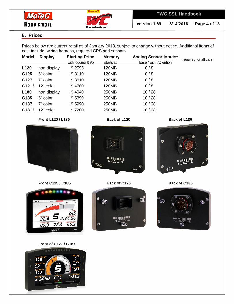
5. Prices
Prices below are current retail as of January 2018, subject to change without notice. Additional items of cost include, wiring harness, required GPS and sensors. Model Display Starting Price Memory Analog Senso r Inputs* with logging & i/o starts at base / with I/O option
L120 non display $ 2595 120MB 0 / 8 C125 5" color $ 3110 120MB 0 / 8 C127 7" color $ 3610 120MB 0 / 8 C1212 12" color $ 4780 120MB 0 / 8 L180 non display $ 4040 250MB 10 / 28 C185 5" color $ 5390 250MB 10 / 28 C187 7" color $ 5990 250MB 10 / 28 C1812 12" color $ 7280 250MB 10 / 28 Front L120 / L180 Back of L120 Back of L180
Front C125 / C185 Back of C125 Back of C185
Front of C127 / C187
*required for all cars
version 1.6 9 3/14/2018 Page 5 of 18
PWC SSL Handbook
6. Option List for Loggers:
These options may be enabled at any time, and never expire on the logger purchased for. I/O Options: Activates additional sensor input pins on the back of the dash. This option is
required for measuring manifold pressure on the 12x series loggers. The 18x series and CDL3 loggers include inputs and won't require purchasing the option. See table above for Analog Sensor Inputs.
Pro Analysis: All data files created on MoTeC loggers can be opened in i2 Standard analysis software. The Pro Logging option enables data files created by the logger to be opened using i2 Pro analysis software. The Pro software adds advanced functions like shock histograms, advanced math equations, unlimited graphs and worksheets, setup sheets, etc. i2 Pro only opens pro files, i2 Standard will open both Pro and Standard data files. All software is free to download.
USB option: This option enables the external USB logging. Many models of MoTeC loggers have the ability to utilize a USB memory stick. Older models won't have the USB port.
L120 C125,C127,C1212 17 I/O $ 400 $ 400 enables sensor inputs and outputs Pro Analysis $ 800 $ 800 enables pro analysis software 250MB / USB $ 525 $ 530 enables additional 120MB logging memory & USB stick T2 telemetry $ 2250 $ 2250 activates the T2 telemetry data stream *radios extra L180 C185,C187,C1812 44 I/O $ 1120 $ 1300 enables sensor inputs and output Pro Analysis $ 1120 $ 1300 enables pro analysis software 500MB / USB $ 890 $ 1040 enables additional 250MB logging memory & USB stick Adv Functions $ 890 $ 1040 enables advanced math, timers, tables T2 telemetry $ 2510 $ 2925 activates the T2 telemetry data stream *radios extra
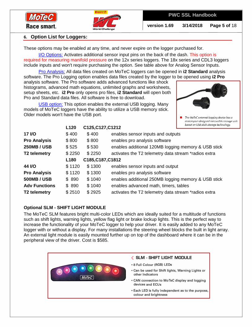
Optional SLM - SHIFT LIGHT MODULE The MoTeC SLM features bright multi-color LEDs which are ideally suited for a multitude of functions such as shift lights, warning lights, yellow flag light or brake lockup lights. This is the perfect way to increase the functionality of your MoTeC logger to help your driver. It is easily added to any MoTeC logger with or without a display. For many installations the steering wheel blocks the built in light array. An external light module is easily mounted further up on top of the dashboard where it can be in the peripheral view of the driver. Cost is $585.
version 1.6 9 3/14/2018 Page 6 of 18
PWC SSL Handbook
Glue Line Shrink #1
Glue Line Shrink #2
Rubber Grommet
Connector Lock
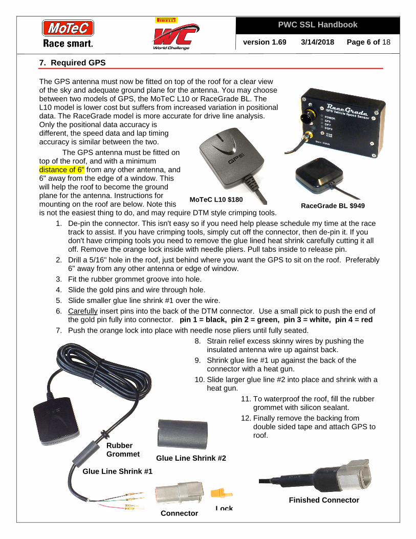
7. Required GPS
The GPS antenna must now be fitted on top of the roof for a clear view of the sky and adequate ground plane for the antenna. You may choose between two models of GPS, the MoTeC L10 or RaceGrade BL. The L10 model is lower cost but suffers from increased variation in positional data. The RaceGrade model is more accurate for drive line analysis. Only the positional data accuracy is different, the speed data and lap timing accuracy is similar between the two.
The GPS antenna must be fitted on top of the roof, and with a minimum distance of 6" from any other antenna, and 6" away from the edge of a window. This will help the roof to become the ground plane for the antenna. Instructions for mounting on the roof are below. Note this is not the easiest thing to do, and may require DTM style crimping tools.
1. De-pin the connector. This isn't easy so if you need help please schedule my time at the race track to assist. If you have crimping tools, simply cut off the connector, then de-pin it. If you don't have crimping tools you need to remove the glue lined heat shrink carefully cutting it all off. Remove the orange lock inside with needle pliers. Pull tabs inside to release pin.
2. Drill a 5/16" hole in the roof, just behind where you want the GPS to sit on the roof. Preferably 6" away from any other antenna or edge of window.
3. Fit the rubber grommet groove into hole. 4. Slide the gold pins and wire through hole. 5. Slide smaller glue line shrink #1 over the wire. 6. Carefully insert pins into the back of the DTM connector. Use a small pick to push the end of
the gold pin fully into connector. pin 1 = black, pin 2 = green, pin 3 = white, pin 4 = red 7. Push the orange lock into place with needle nose pliers until fully seated.
8. Strain relief excess skinny wires by pushing the insulated antenna wire up against back.
9. Shrink glue line #1 up against the back of the connector with a heat gun.
10. Slide larger glue line #2 into place and shrink with a heat gun.
11. To waterproof the roof, fill the rubber grommet with silicon sealant.
12. Finally remove the backing from double sided tape and attach GPS to roof.
RaceGrade BL $949 MoTeC L10 $180
Finished Connector
version 1.6 9 3/14/2018 Page 7 of 18
PWC SSL Handbook
8. WIRING HARNESS
Custom wiring harnesses are available for teams using the Motec logger as their main data logger. Or a simple standard harness is available and can be configured for custom lengths upon request. The required connections for all cars are:
1. Battery 12v Positive & Ground 2. GPS 3. CAN or OBDii communications 4. Manifold Pressure sensor 5. Download / PC connection - RJ45 connection recommended to logger. For teams with
any alternative download port connection type, a RJ45 adapter cable must be provided to PWC for use during the weekends for use in tech. Location must be within an arm's reach of the passenger mirror.
6. Yellow Flag / Track Condition radio connection
Requirement for Manifold Pressure All cars must have an external visually traceable wire lead from the main connector of the dash
straight through to the manifold pressure sensor. It can not be bundled with any other wires and shall contain only 3 wires; 0v, signal & 5v. Connectors in the path from the logger to the sensor, such as a firewall connector, must also not contain any other wires. Connections, wiring pinouts and installation is subject to inspection at any time.
CAN Connection For cars which come with a FIA or SRO spec logger connection, most of the required channels can be logged off that CAN stream. Details can be found in the Section 11 further down in this document. For other cars, a direct connection to the factory CAN bus with decoding information is required. If the factory CAN is not available, OBDii may be used with approval of PWC in TC, TCA classes only. Please refer to the required channel list to make sure you can comply with the regulations. CAN channels must come directly from the originating source, and all vehicle CAN data transmission is subject to inspection at any time.
version 1.6 9 3/14/2018 Page 8 of 18
PWC SSL Handbook
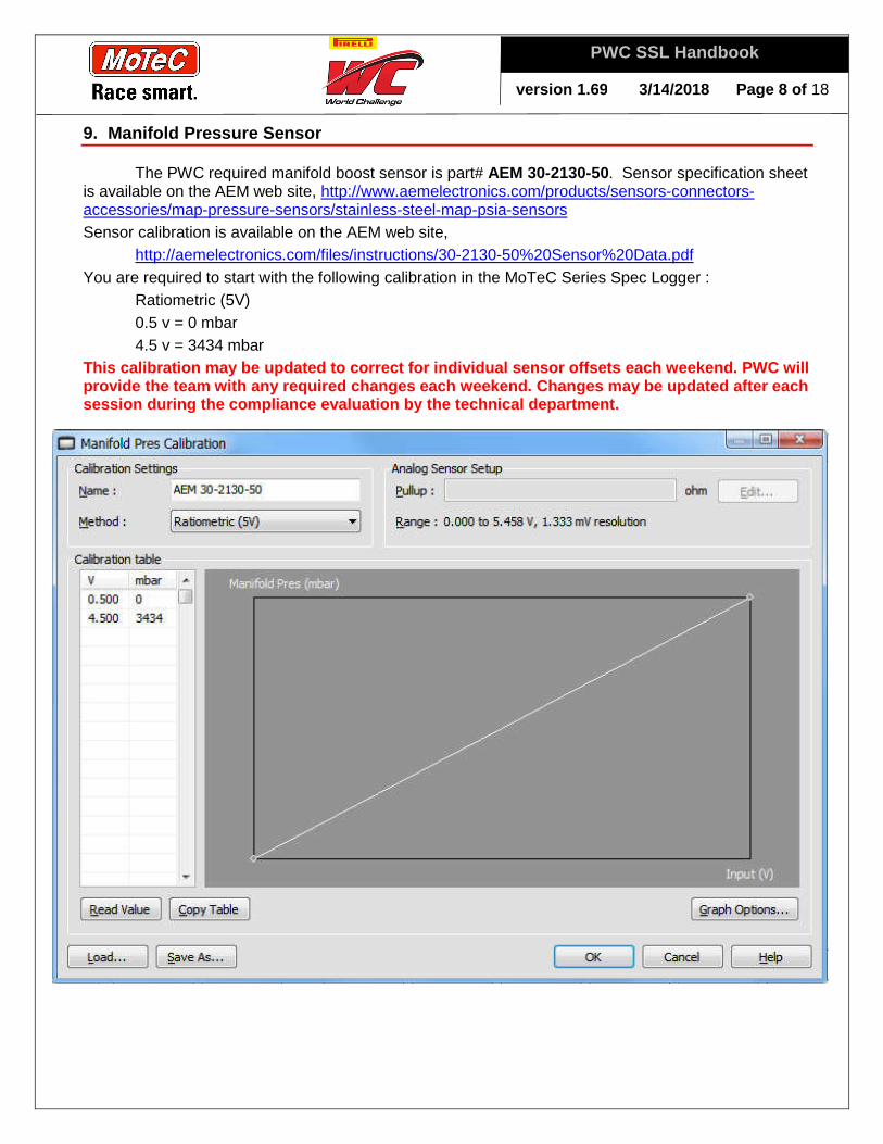
9. Manifold Pressure Sensor
The PWC required manifold boost sensor is part# AEM 30-2130-50. Sensor specification sheet is available on the AEM web site, http://www.aemelectronics.com/products/sensors-connectors-accessories/map-pressure-sensors/stainless-steel-map-psia-sensors Sensor calibration is available on the AEM web site,
http://aemelectronics.com/files/instructions/30-2130-50%20Sensor%20Data.pdf You are required to start with the following calibration in the MoTeC Series Spec Logger :
Ratiometric (5V) 0.5 v = 0 mbar 4.5 v = 3434 mbar
This calibration may be updated to correct for indi vidual sensor offsets each weekend. PWC will provide the team with any required changes each wee kend. Changes may be updated after each session during the compliance evaluation by the tec hnical department.
version 1.6 9 3/14/2018 Page 9 of 18
PWC SSL Handbook
10. REQUIRED CHANNELS
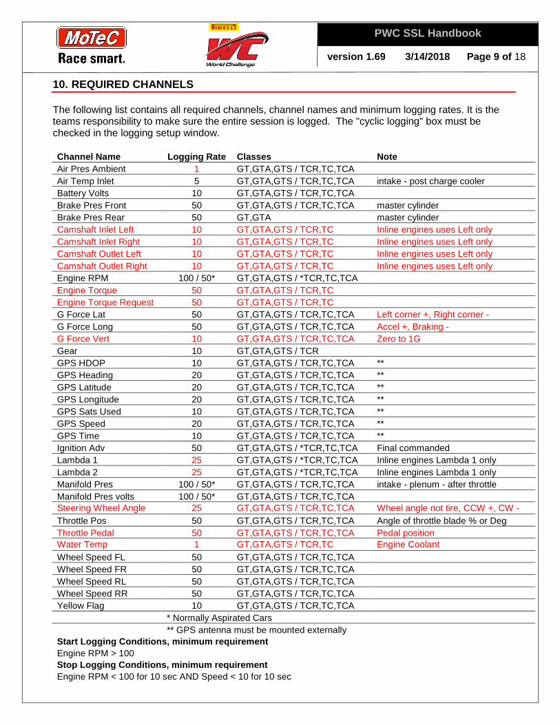
The following list contains all required channels, channel names and minimum logging rates. It is the teams responsibility to make sure the entire session is logged. The "cyclic logging" box must be checked in the logging setup window.
Channel Name Logging Rate Classes Note Air Pres Ambient 1 GT,GTA,GTS / TCR,TC,TCA Air Temp Inlet 5 GT,GTA,GTS / TCR,TC,TCA intake - post charge cooler Battery Volts 10 GT,GTA,GTS / TCR,TC,TCA Brake Pres Front 50 GT,GTA,GTS / TCR,TC,TCA master cylinder Brake Pres Rear 50 GT,GTA master cylinder Camshaft Inlet Left 10 GT,GTA,GTS / TCR,TC Inline engines uses Left only Camshaft Inlet Right 10 GT,GTA,GTS / TCR,TC Inline engines uses Left only Camshaft Outlet Left 10 GT,GTA,GTS / TCR,TC Inline engines uses Left only Camshaft Outlet Right 10 GT,GTA,GTS / TCR,TC Inline engines uses Left only Engine RPM 100 / 50* GT,GTA,GTS / *TCR,TC,TCA Engine Torque 50 GT,GTA,GTS / TCR,TC Engine Torque Request 50 GT,GTA,GTS / TCR,TC G Force Lat 50 GT,GTA,GTS / TCR,TC,TCA Left corner +, Right corner - G Force Long 50 GT,GTA,GTS / TCR,TC,TCA Accel +, Braking - G Force Vert 10 GT,GTA,GTS / TCR,TC,TCA Zero to 1G Gear 10 GT,GTA,GTS / TCR GPS HDOP 10 GT,GTA,GTS / TCR,TC,TCA ** GPS Heading 20 GT,GTA,GTS / TCR,TC,TCA ** GPS Latitude 20 GT,GTA,GTS / TCR,TC,TCA ** GPS Longitude 20 GT,GTA,GTS / TCR,TC,TCA ** GPS Sats Used 10 GT,GTA,GTS / TCR,TC,TCA ** GPS Speed 20 GT,GTA,GTS / TCR,TC,TCA ** GPS Time 10 GT,GTA,GTS / TCR,TC,TCA ** Ignition Adv 50 GT,GTA,GTS / *TCR,TC,TCA Final commanded Lambda 1 25 GT,GTA,GTS / *TCR,TC,TCA Inline engines Lambda 1 only Lambda 2 25 GT,GTA,GTS / *TCR,TC,TCA Inline engines Lambda 1 only Manifold Pres 100 / 50* GT,GTA,GTS / TCR,TC,TCA intake - plenum - after throttle Manifold Pres volts 100 / 50* GT,GTA,GTS / TCR,TC,TCA Steering Wheel Angle 25 GT,GTA,GTS / TCR,TC,TCA Wheel angle not tire, CCW +, CW - Throttle Pos 50 GT,GTA,GTS / TCR,TC,TCA Angle of throttle blade % or Deg Throttle Pedal 50 GT,GTA,GTS / TCR,TC,TCA Pedal position Water Temp 1 GT,GTA,GTS / TCR,TC Engine Coolant Wheel Speed FL 50 GT,GTA,GTS / TCR,TC,TCA Wheel Speed FR 50 GT,GTA,GTS / TCR,TC,TCA Wheel Speed RL 50 GT,GTA,GTS / TCR,TC,TCA Wheel Speed RR 50 GT,GTA,GTS / TCR,TC,TCA Yellow Flag 10 GT,GTA,GTS / TCR,TC,TCA * Normally Aspirated Cars
** GPS antenna must be mounted externally Start Logging Conditions, minimum requirement Engine RPM > 100 Stop Logging Conditions, minimum requirement Engine RPM < 100 for 10 sec AND Speed < 10 for 10 sec

version 1.6 9 3/14/2018 Page 10 of 18
PWC SSL Handbook
11. CAN CONNECTION DETAILS
Many cars already feature a GT3 or GT4 Spec Logger connection, with the following CAN channels listed below. It is also allowed to connect and read the vehicle's factory CAN bus to gather the required channels. Many forms of this are eligible, please contact Chris Brown for further details. Note: Refer to manufacturer for approval before connecting to any existing CAN bus!
FIA GT3 Logger CAN
Channel CAN ID
Byte order
Start bit Length Value
type Scale Offset Units
Throttle Pedal 0x168 Motorola 0 16 Unsigned 0.1 0 % Throttle Engine 0x168 Motorola 16 16 Unsigned 0.1 0 % RPM (Crank) 0x168 Motorola 32 16 Unsigned 1 0 rpm Lambda R 0x168 Motorola 48 16 Unsigned 0.01 0 lambda Lambda L 0x178 Motorola 0 16 Unsigned 0.01 0 lambda Brake Pres Front or FL 0x170 Motorola 0 16 Signed 0.1 0 bar N/A or Brake Pres FR 0x170 Motorola 16 16 Signed 0.1 0 bar Brake Pres Rear or RL 0x170 Motorola 32 16 Signed 0.1 0 bar N/A or Brake Pres RR 0x170 Motorola 48 16 Signed 0.1 0 bar Water Temp 0x172 Motorola 0 8 Unsigned 1 0 °C Fuel Temp 0x172 Motorola 8 8 Unsigned 1 0 °C Fuel 0x172 Motorola 16 16 Unsigned 0.1 0 liter Airbox Temp 0x172 Motorola 32 8 Unsigned 1 0 °C Gear 0x172 Motorola 40 8 Unsigned 1 0 Unused 0x172 Motorola 48 16 WheelSpeed FL 0x174 Motorola 0 16 Unsigned 0.1 0 km/h WheelSpeed FR 0x174 Motorola 16 16 Unsigned 0.1 0 km/h WheelSpeed RL 0x174 Motorola 32 16 Unsigned 0.1 0 km/h WheelSpeed RR 0x174 Motorola 48 16 Unsigned 0.1 0 km/h Fuel Qty injected 0x176 Motorola 0 16 Unsigned 0.01 0 mg Steering Angle 0x176 Motorola 16 16 Signed 0.27 0 deg Boost pressure 0x176 Motorola 32 16 Unsigned 1 0 mbar Ignition advance 0x176 Motorola 48 16 Signed 0.1 0 %
FIA GT3 car side: DTM 4S, logger side: DTM 4P Pin# - Function 1 - CAN High 2 - CAN Low 3 - Power +12v 4 - Ground 0v
SRO GT3 car side: DTM 6P, logger side: DTM 6S Pin# - Function 1 - Ground 0v 2 - not connected 3 - not connected 4 - Power +12v 5 - CAN High 6 - CAN Low

version 1.6 9 3/14/2018 Page 11 of 18
PWC SSL Handbook
12. TIRE DIAMETERS
Tire Diameters, and / or applicable CAN scalars must be adhered to, and will be corrected to match GPS Speed and verified with lap distance. These corrections may be adjusted throughout the year and specified by PWC to the team for each vehicle.
13. DATA GATHERING - Downloading & SD Memory Card s
At certain events where logistics permit, all cars will be required to roll through a lineup immediately upon exiting the racing circuit. Data will be downloaded by PWC officials before the cars are released to their paddock / garage / tent. When this is not possible, all teams will be given SD memory cards during the crew chief meeting. These will be numbered for all official sessions, typically Practice, Qualifying and Races. SD cards must be turned in within 30 minutes of the conclusion of every session with the corresponding original data files. Additionally data will be downloaded directly from all cars passing through tech. Teams are no longer allowed to download data from cars in tech. Teams with cars in tech are to turn in an empty SD card. All data cards must be returned at the conclusion of the event, including any unused cards. Upon any downloading from a series official, logging memory will not be erased and it will be the requirement of the team to clear the data before the next official session begins.
14. Logger Serial #
All MoTeC logger serial numbers must be on file with PWC. This includes any spare units.
15. CONFIGURATION FILES
All logger device configuration files must remain open to PWC. No passwords are allowed without disclosing them to PWC. Data files without the device config will be deemed non-compliant. The series will keep a master copy of all configuration files to be used in the event of communication and sensor verification, (i.e. CAN setup and boost sensor input identification).
16. SOFTWARE / FIRMWARE VERSIONS
All logger devices will need to be on the minimum versions of software: C125, C127, C1212, L120, C185, C187, C1812m L180 = version 6.03E CDL3 = version 1.60Z ADL3 / EDL3 = version 5.60Z SDL3 = version 2.60Z ACL = version 1.70Z8 Any variation from above must be pre-approved by PWC.

version 1.6 9 3/14/2018 Page 12 of 18
PWC SSL Handbook
17. MOTEC DATA FILE DETAILS SETUP
To keep data files standardized, some detail information guidelines are required. An example image of the details editor is shown below.
Event Name It is recommended but not
required to put "PWC" in the event name. It is not recommended to put the track name in the event name.
Session It is recommended but not
required to use the following convention: Test 1, Prac 1, Qual, Race 1, etc.
Short + Long Comments No requirement. The Short
Comment appears in the file open menu so it can be used to quickly identify a certain session. Things like "driver crashed", "rained", "+2deg wing", "new tire set #3", etc.
Venue / Track Details To keep data files standardized the venue or track name must follow the list below, and use the
official GPS locations for start/finish and section time locations. When managing these venues, it's recommended not to grab all North American tracks, only those which you will visit. A complete list of PWC venue files are available to download and load into your laptop.
Venue Name GPS Lat, Long St. Petersburg 27.7651389, -82.6294666
COTA * 30.1335278, -97.6422583
Long Beach 33.7622611, -118.1872277
VIR * 36.5688167, -79.2066639
Mosport * 44.0543639, -78.6744083
Lime Rock * 41.9286028, -73.3810055
Road America 43.7979056, -87.9896333
Portland * 45.5950361, -122.6945222
Utah Outer * 40.5831556, -112.3763888
Watkins Glen * 42.3410361, -76.9288472
Laguna Seca 36.5863000, -121.7567833
* TCR/TC/TCA races in addition to the GT classes NOTE: Please verify all GPS coordinates from all tracks as they will not match default Motec ones ! NOTE: Pre configured venue files are available from Chris Brown. NOTE: Changes from last year are in red.
version 1.6 9 3/14/2018 Page 13 of 18
PWC SSL Handbook
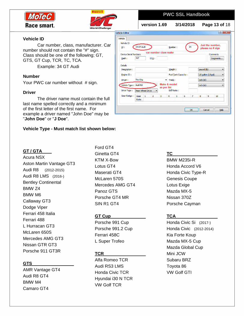
Vehicle ID Car number, class, manufacturer. Car
number should not contain the "#" sign. Class should be one of the following; GT, GTS, GT Cup, TCR, TC, TCA.
Example: 34 GT Audi
Number Your PWC car number without # sign.
Driver The driver name must contain the full
last name spelled correctly and a minimum of the first letter of the first name. For example a driver named "John Doe" may be "John Doe " or "J Doe ".
Vehicle Type - Must match list shown below:
GT / GTA Acura NSX Aston Martin Vantage GT3 Audi R8 (2012-2015) Audi R8 LMS (2016-) Bentley Continental BMW Z4 BMW M6 Callaway GT3 Dodge Viper Ferrari 458 Italia Ferrari 488 L Hurracan GT3 McLaren 650S Mercedes AMG GT3 Nissan GTR GT3 Porsche 911 GT3R GTS AMR Vantage GT4 Audi R8 GT4 BMW M4 Camaro GT4
Ford GT4 Ginetta GT4 KTM X-Bow Lotus GT4 Maserati GT4 McLaren 570S Mercedes AMG GT4 Panoz GTS Porsche GT4 MR SIN R1 GT4 GT Cup Porsche 991 Cup Porsche 991.2 Cup Ferrari 458C L Super Trofeo TCR Alfa Romeo TCR Audi RS3 LMS Honda Civic TCR Hyundai i30 N TCR VW Golf TCR
TC BMW M235i-R Honda Accord V6 Honda Civic Type-R Genesis Coupe Lotus Exige Mazda MX-5 Nissan 370Z Porsche Cayman TCA Honda Civic Si (2017-)
Honda Civic (2012-2014) Kia Forte Koup Mazda MX-5 Cup Mazda Global Cup Mini JCW Subaru BRZ Toyota 86 VW Golf GTI
version 1.6 9 3/14/2018 Page 14 of 18
PWC SSL Handbook
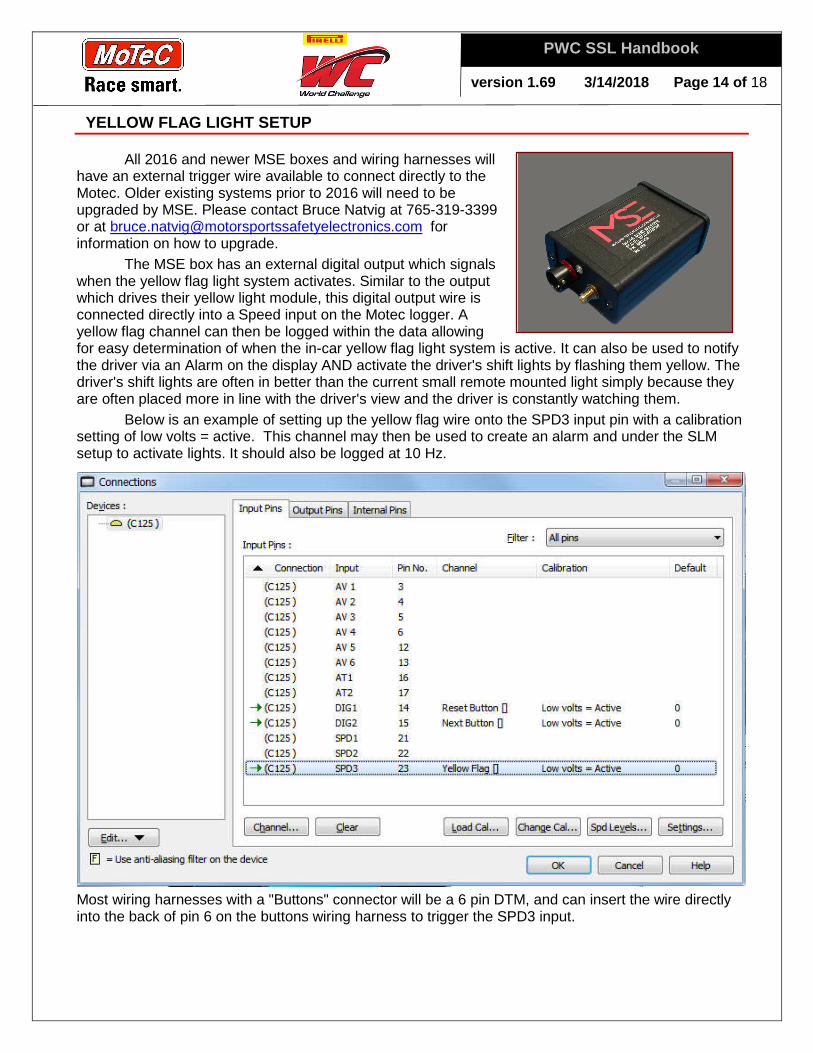
YELLOW FLAG LIGHT SETUP
All 2016 and newer MSE boxes and wiring harnesses will have an external trigger wire available to connect directly to the Motec. Older existing systems prior to 2016 will need to be upgraded by MSE. Please contact Bruce Natvig at 765-319-3399 or at [email protected] for information on how to upgrade.
The MSE box has an external digital output which signals when the yellow flag light system activates. Similar to the output which drives their yellow light module, this digital output wire is connected directly into a Speed input on the Motec logger. A yellow flag channel can then be logged within the data allowing for easy determination of when the in-car yellow flag light system is active. It can also be used to notify the driver via an Alarm on the display AND activate the driver's shift lights by flashing them yellow. The driver's shift lights are often in better than the current small remote mounted light simply because they are often placed more in line with the driver's view and the driver is constantly watching them. Below is an example of setting up the yellow flag wire onto the SPD3 input pin with a calibration setting of low volts = active. This channel may then be used to create an alarm and under the SLM setup to activate lights. It should also be logged at 10 Hz.
Most wiring harnesses with a "Buttons" connector will be a 6 pin DTM, and can insert the wire directly into the back of pin 6 on the buttons wiring harness to trigger the SPD3 input.
version 1.6 9 3/14/2018 Page 15 of 18
PWC SSL Handbook
18. ANALYSIS SOFTWARE INFORMATION
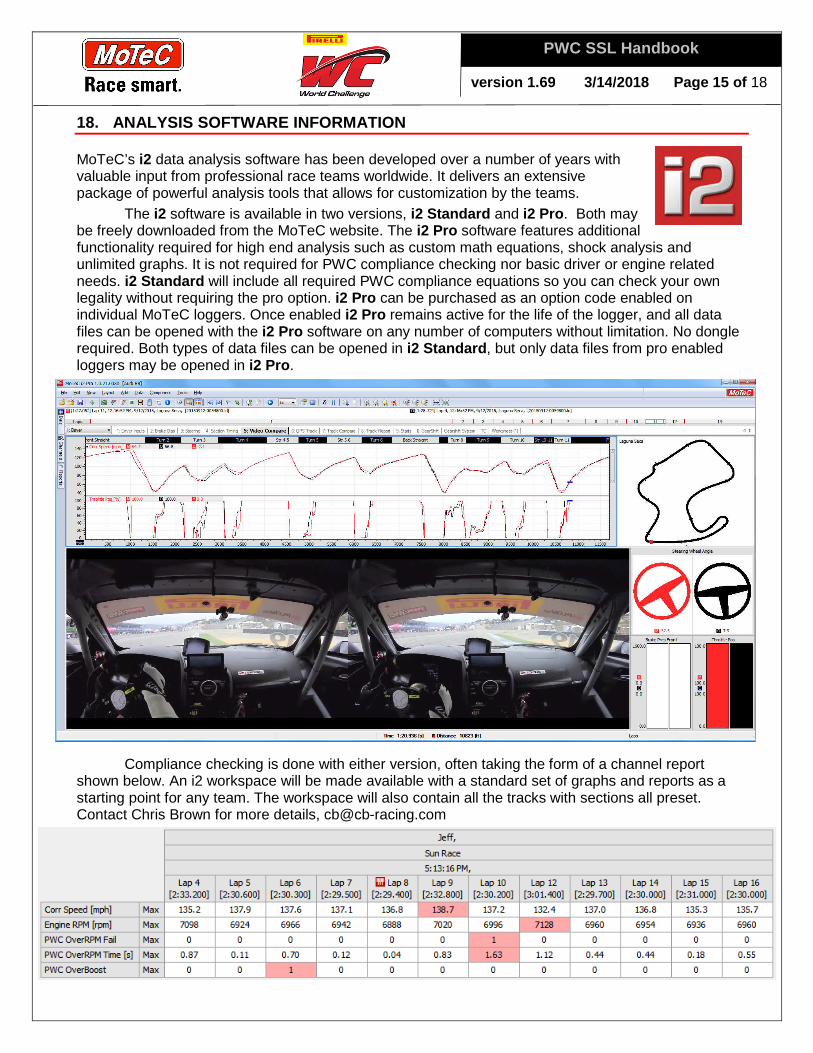
MoTeC’s i2 data analysis software has been developed over a number of years with valuable input from professional race teams worldwide. It delivers an extensive package of powerful analysis tools that allows for customization by the teams.
The i2 software is available in two versions, i2 Standard and i2 Pro. Both may be freely downloaded from the MoTeC website. The i2 Pro software features additional functionality required for high end analysis such as custom math equations, shock analysis and unlimited graphs. It is not required for PWC compliance checking nor basic driver or engine related needs. i2 Standard will include all required PWC compliance equations so you can check your own legality without requiring the pro option. i2 Pro can be purchased as an option code enabled on individual MoTeC loggers. Once enabled i2 Pro remains active for the life of the logger, and all data files can be opened with the i2 Pro software on any number of computers without limitation. No dongle required. Both types of data files can be opened in i2 Standard, but only data files from pro enabled loggers may be opened in i2 Pro.
Compliance checking is done with either version, often taking the form of a channel report shown below. An i2 workspace will be made available with a standard set of graphs and reports as a starting point for any team. The workspace will also contain all the tracks with sections all preset. Contact Chris Brown for more details, [email protected]
version 1.6 9 3/14/2018 Page 16 of 18
PWC SSL Handbook
19. INSTALLATION & MOUNTING GUIDELINES
At this time there are no requirements for locating the logger at a specific location from the center of mass. Just a requirement to keep the axis aligned with the directions of the vehicle. Therefore the loggers may be mounted anywhere in the car, but care should be exercised to keep the logger in a matching orthogonal axis with respect to the car. Please note the following:
1. Accelerometer data will be reviewed and must be corrected upon request of PWC. 2. The internal accelerometer axis directions can be reassigned to keep G Force Lateral,
Longitudinal and Vertical orientated with respect to the vehicle depending on mounting orientation of the logger.
3. Accelerometers must be mounted within 3 degrees of the orthogonal axis of the vehicle. For Motec display loggers where the display is angled for driver viewing, an external accelerometer must be used. Note some car's may already have an external accelerometer typically used by the ABS system which can be used in place of the internal accelerometer on the Motec data logger. All sensors must be zero'd on a setup pad to provide proper readings.
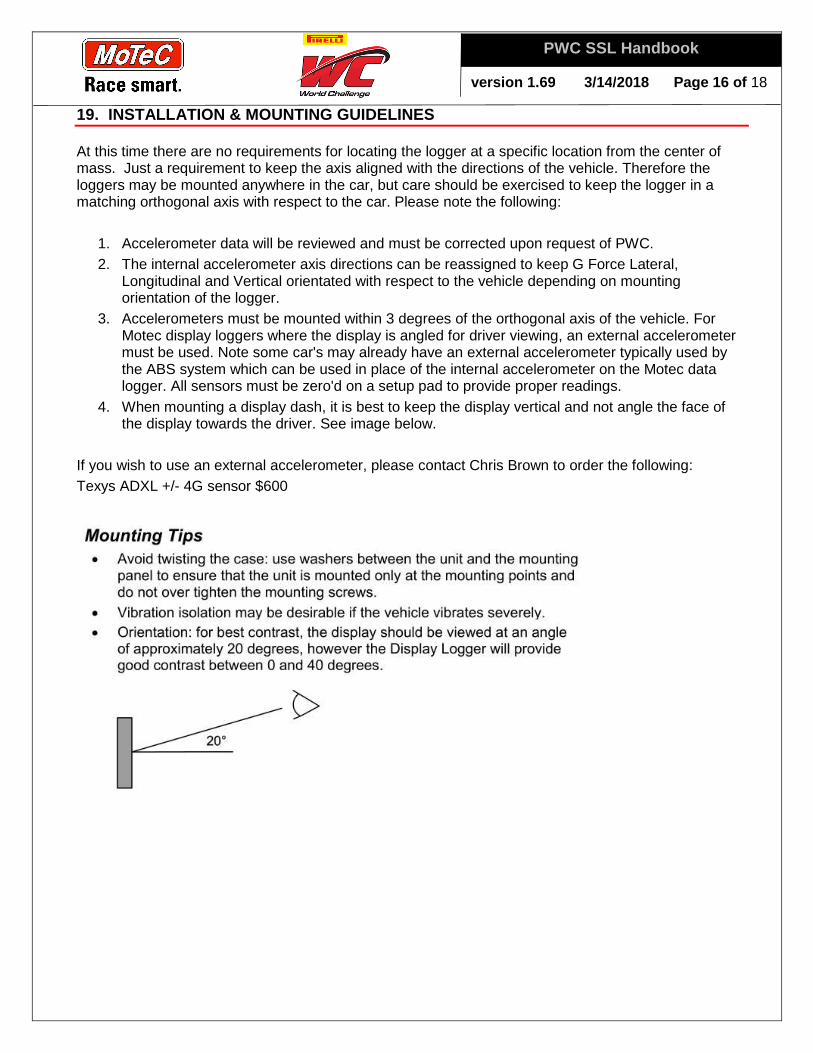
4. When mounting a display dash, it is best to keep the display vertical and not angle the face of the display towards the driver. See image below.
If you wish to use an external accelerometer, please contact Chris Brown to order the following: Texys ADXL +/- 4G sensor $600

version 1.6 9 3/14/2018 Page 17 of 18
PWC SSL Handbook
20. TRAINING
From its large install base around the world, there are many people already familiar with the MoTeC software. For those that aren't training is available.
• user manuals available at www.motec.com
• seminar / class PDF files available at www.squigglylines.com
• online webinars available at www.motec.com or www.squigglylines.com
• help files can be found in the software by clicking "F1" or going to the help menu
• training classes full day classroom instruction taught by www.squigglylines.com
Training classes will be taught throughout the year. Cost for classroom training is done on a per person basis, approximately $300/day/person. Online training is also starting up in 2018. These training classes are presented by Christopher Brown who had previously taught MoTeC Systems USA's training seminars for many years. The training is structured using various examples and illustrations with plenty of opportunity for questions and feedback throughout the day. Participants are required to bring their own laptops and all required software and example data will be distributed during the class. Printed notebooks of the slides are provided and utilized during the class for note taking. Remote training, On-Site training and consulting is also available on request.
Please visit www.squigglylines.com for a complete schedule.
version 1.6 9 3/14/2018 Page 18 of 18
PWC SSL Handbook
21. TECHNICAL SUPPORT
Technical support is available to the teams from their MoTeC dealer. Team may also contact the PWC authorized MoTeC support dealer, Christopher Brown Racing. Chris Brown would be your single point of contact for any series related questions. As a backup or for additional support MoTeC USA is available and will work closely with Chris on all support issues. Support for installation and operation is available in a number of ways: » Track support » Onsite shop support » Online / Remote support » Telephone support » Email support
Email support is typically free of charge. Remote online support may be the quickest using the free TeamViewer PC software to control the user's laptop to review data, solve problems or configure dash products though the internet. An hourly rate is charged for remote online support, and extended phone support. Support at team workshops or private test and track sessions and PWC race weekends can be provided and structured into an hourly, daily or weekend rate depending on your support needs.
Please visit www.squigglylines.com for additional support.
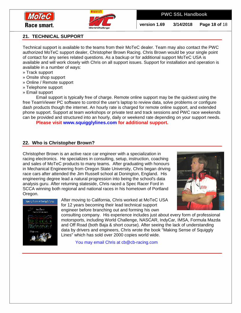
22. Who is Christopher Brown?
Christopher Brown is an active race car engineer with a specialization in racing electronics. He specializes in consulting, setup, instruction, coaching and sales of MoTeC products to many teams. After graduating with honours in Mechanical Engineering from Oregon State University, Chris began driving race cars after attended the Jim Russell school at Donington, England. His engineering degree lead a natural progression into being the school's data analysis guru. After returning stateside, Chris raced a Spec Racer Ford in SCCA winning both regional and national races in his hometown of Portland Oregon.
After moving to California, Chris worked at MoTeC USA for 12 years becoming their lead technical support engineer before branching out and forming his own consulting company. His experience includes just about every form of professional motorsports, including World Challenge, NASCAR, IndyCar, IMSA, Formula Mazda and Off Road (both Baja & short course). After seeing the lack of understanding data by drivers and engineers, Chris wrote the book "Making Sense of Squiggly Lines" which has sold over 2000 copies world wide.
You may email Chris at [email protected]