6.3 earthquake resistant plan for facilities structure and
TRANSCRIPT

6 - 41
6.3 Earthquake Resistant Plan for Facilities Structure and Equipment
This section is related to Damage estimations described earlier in section 4.2, and also shown in Figure
6.3.1 below.
Since target facilities are so many and conditions are complicated, study was carried out systematically
through three steps in the process of Risk Management. In the first two steps, the risks were defined
through site survey and brainstorming (1Risk Factor Analysis) and the damages were estimated on the
basis of fourteen risks (2Risk Assessment) so far. In this section of the study, the last stage is
undertaken which includes formulation and proposing of countermeasures on concerned risks (3Risk
Control).
Figure 6.3.1 Flowchart of Related Tasks in This Section
1 Risk Factor Analysis To define the risks
- Site survey - Japanese experience - Iranian Brainstorming
2 Risk Assessment To estimate the damage
- Japanese DTSC※ (based on major 14 risks)
- Structural analysis
3 Risk Control to plan the measures to control risks.
- Actual example /common measure
- Structural analysis
- Damage Estimation on Scenario Earthquake
List of Risks
Earthquake-resistant Plan - List of Earthquake-resistant
countermeasures against Risks - Outline Drawing
※DTSC: Diagnostic Table of Seismic Capacity
- Design Based Earthquake Resistance Map on Code 2800
- Target Facilities
Manual for Seismic Diagnosis
4.2 Damage estimations
6.3 Earthquake Resistant Plan

6 - 42
6.3.1 General Conditions
(1) Design Conditions for Earthquake Resistant Plan 1) Principle of Target Facilities
Three of obvious facts are declared so far,
− One is that the facilities on fault in the case of North Tehran scenario earthquake of rare occurrence probability would be assumed seriously damaged.
− Another is that the Code on seismic design for building has been enforced for one decade and many facilities have been designed in accordance with Code 2800 after its enforcement.
− Also, TWWC intends to carry out seismic reinforcement of existing facilities.
Therefore we should consider that TWWC could transform smoothly to future design and construction stages. Hence, target facilities in study should be selected considering these situations, and we have categorized the target facilities as follows.
− Category A: The facilities on fault and other fragile facilities based on disastrous North Tehran scenario earthquake
− Category B: The fragile facilities evaluated by code 2800 on Design-Based Earthquake Resistance Map without condition of fault
a) Principle of the Measure for Facilities of Category A
Regarding the damage estimations on North Tehran scenario earthquake, only the facilities on fault are assumed seriously damaged. It is almost acceptable to design pipe on fault, but impossible for bigger items like building/tank. The countermeasure for building/tank on fault should be strengthening the foundation through measures of thick and expanded ground improvement against the ground displacement on faults. Moreover, considering the expenses on the physical measure against rare occurrence possibility of scenario earthquake, it is technically and economically difficult to implement physical measure. Therefore, the measures in terms of Minimization of Damage Effect such as back up with pipe/other neighboring facilities are applicable in the short term, and in the future it should be responded by relocation/re-planning of water supply system after the service of facilities would be fulfilled. If it is so, physical countermeasure against earthquake is not required for Category A.
b) Principle of the Measure on Facilities of Category B
On the other hand, Iran has a code 2800 for building, which came into effect legally after Roodbar-Manjil earthquake in 1990, and thereafter many seismic designed building have been designed/ constructed based on Code 2800. Therefore, in this Study, concrete measure must be analyzed in the same manner in terms of Minimization of Damage Occurrence.
Some considerations should be studied in terms of Minimization of Damage Effect though.
2) Approach on Study
As mentioned above, the strategy of countermeasure is diverse, and therefore approaches on study of countermeasure would be categorized into two, one is proper measure of Minimization of Damage Occurrence, and the other is Minimization of Damage Effect.

6 - 43
3) Evaluation Period
Seismic acceleration of 0.35G on code 2800, which is of a 100-year occurrence probability, is appropriate to be applied to public works in terms of facilities’ service life (a 50-year span for RC structure), economical efficiency, and the acceptable level for the citizens, so that proper physical countermeasure would be carried out for seismic acceleration of 0.35G.
Therefore, as implementation program of physical countermeasure is mainly on the facilities of Category B, feasibility of program would be evaluated on the basis of 100-year span.
4) Design-Based Earthquake resistance Map
Toward the implementation of program, Earthquake-resistant design starts based on previous damage estimations on scenario earthquake and present situations of Design-Based Earthquake resistance Map on the condition of code 2800 shown in Figure 6.3.2 of which structural fragility is made by DTSC. Feature of Earthquake resistance Map is shown below.
According to the Map, as Generator Houses in WTP No.1 and No.2 are very fragile because of long span structure, measures would be required. Since other facilities are slightly fragile, measures should be carried out one by one starting from older facilities to the new ones considering their age and feasibility.
5) Disaster Map
Fire, gas poisoning or loss of human life might occur near the location of Generator, Transformer, Chlorine Dosing Equipment and Facilities on the cliff, and hence these facilities have potentially high-risk of disasters in case of earthquake occurrence.
When the earthquake-resistant measures are carried out, these disasters would be cleared up/mitigated, so the location of these risks would be marked on Secondary Disaster Map shown in Figure 6.3.3 for the awareness/knowledge in the study.
6) Ground/Soil conditions
Ground conditions, which were sorted out on study of Seismic Motion Analysis, were enough for the purpose of this Study. Several structural analysis have been performed to verify the DTSC and to prepare an outline of countermeasures against risks for reference.
In this study, for the structural analysis of required soil conditions of Pump house No.2, Reservoir No.6 and Pulsator in WTP No.2, since the specific soil data just on the ground behind the wall of the tank/pump chamber were not available, study team adopted sandy gravel on the basis of visual investigations and the data of categorized ground on study of Seismic Motion Analysis. As a consequence, friction angle was assumed 40 degrees on the safe side for the case of sandy gravel to calculate the active earth pressure during earthquakes.
In the near future, when the detail design of underground chamber/tank would be carried out, the specific soil data (N value, friction angle, uniaxial compressive strength, etc.) for the location behind the wall might be required. This is because the need of countermeasures is determined by the soil conditions.

6 - 44
Figure 6.3.2 Design-Based Earthquake Resistance Map (present; A=0.35, without condition of fault)
47 348 1
48 2492
483 484
501
52 1
53 1
5 415 42543
5 525 54
53 2
57 3
5 82
583
5 92
6 02
56 1
562
6 21
801
802 803
804
805
806 807
810
809
808
819
833
818
811
812
813
814
8151 816
817
820
821822
823
824
825
826
827
828 829
830
831
832
834
835
S hahrak sadr
W 101
Nas erieh
P
PP
P
P P
P
P
P
P
PP
P
P
P
P
P
P
P
P
P
P
P
P
P
P P
P P
PP P
P P
P P
P
P
P
P
P
P
P
P
P
PP
P
P
P
P
P
P
P
P
P
PP
P
P
P
P
P
G
G
P
P
P
P
P
P
P
PP
P
P
P
P
PP
P
PP
P
P
P
P P
P
P
P
P
P
P
P
P
P
tarasht pum ping s tation
E sfahanak
Res erv o ir No.89fresh fruit & v egtable
s quare
K haniabadS hariati
V aliasr
FerdowsY aftabad
17th of s hahrivar
Mos hirieh
E sfah anakp ump ststion
Res ervoir no.16
Q as r-e-F irouzeh
E igehi
Res alat
R esa lat(Araqi)
Res ervoirno.11
Res ervoirno.42
Res ervoirno.40
Res ervoirno.41
Res ervoirno.21
Aqdas iehOzgol
Res ervoirno.2
Res ervoirno.3
Res ervoirno.4
R eservoirno.5
Res ervoirno.6
s outhern taras ht
Southern tarasht pum p s tation
Res ervoirno.13
Mehrabad
ja lalieh
Taras ht107& 108
Dam water
Raw water conduit
K araj dam
K an
Maqs odbeyk
104
114
2000
4000 3000
5000
1000
e levated tankexist
not used
2 01
203
2 04 207 208 209 211 212 214 21 6 2 17 218
23 1
219
221
2 41 2 45 24 6 247 248
25 1 2 52 25 3 2 55 25 6
261
2 71
282
30 5 306
3 07
3 11
31 2
31 3
31 4
32 1 32 2
3 4135 1
352
342 361
372
3 91
3 92
393
38 1
401 41 1
421
422
441
4 42
45245 3
46 2 46 147 1
P
P
P
6 - 44

6 - 45
Figure 6.3.3 Secondary Disaster Map
: Oil Leakage from Generator Fuel Tank: Fire from Transformer: Gas Leakage from Chlorine Dosing Equipment
GTrCl
G
G
G
G
Tr
Tr
TrTr
Tr
Tr
Tr
TrTr
Tr
Tr
Tr
Tr Tr
Tr
Tr
Tr
Tr
Tr Cl
Tr
Tr
Tr
Tr
Tr
TrTr Cl
ClClClCl
Cl
Cl
Cl Cl
Cl
Cl Cl
Cl
Cl
Cl ClCl
Cl
Cl
Cl
Cl
Cl
t arasht pum pi ng station
E sfahanak
Reservo ir No.89fre sh fru it & veg table
square
K haniabadS ha riati
V alia sr
Ferd owsY aftabad
1 7th of sha hrivar
Moshirieh
E sfahanakpump ststion
Re se rvoir no.16
Q asr-e-Firo uzeh
E ig ehi
Resa lat
R esalat(Araqi)
Reservo irno.11
Reservo irno.42
Reservo irno.40
Reservo irno.41
Reservo irno.21
AqdasiehOzgol
Reservo irno.2
Reservo irno.3
Reservo irno.4
R eservoirno.5
Reservo irno.6
south ern tara sht
Southern tarasht pump station
Reservo irno.13
Mehrabad
ja la lieh
Tara sht107&108
Dam water
Raw water conduit
K araj dam
Kan
Maqso dbeyk
104
114
2000
4000 3000
5000
1000
e leva ted tanke xist
n ot used
801
802 803
804
805
806 807
810
809
808
819
833
818
811
812
813
814
8151 816
817
820
821822
823
824
825
826
827
828 829
830
831
832
834
835
S hah rak sadr
W 101
Naserieh
P
PP
P
P P
P
P
P
P
PP
P
P
P
P
P
P
P
P
P
P
P
P
P
P P
P P
PP P
P P
P P
P
P
P
P
P
P
P
P
P
P
P
P
P
P
P
PP
P
P
P
P
P
P
P
P
P
P
P
P
PP
P
P
P
P
PP
P
PP
P
P
P
P P
P
P
P
P
P
P
P
P
P
: In Danger Of Secondary Disaster
Bilagan
ShelterG Tr Cl
6 - 45
6 - 46
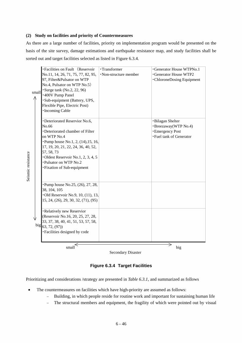
(2) Study on facilities and priority of Countermeasures
As there are a large number of facilities, priority on implementation program would be presented on the
basis of the site survey, damage estimations and earthquake resistance map, and study facilities shall be
sorted out and target facilities selected as listed in Figure 6.3.4.
Figure 6.3.4 Target Facilities
Prioritizing and considerations /strategy are presented in Table 6.3.1, and summarized as follows
• The countermeasures on facilities which have high-priority are assumed as follows: − Building, in which people reside for routine work and important for sustaining human life − The structural members and equipment, the fragility of which were pointed out by visual
・Facilities on Fault (ReservoirNo.11, 14, 26, 71, 75, 77, 82, 95,97, Filter&Pulsator on WTPNo.4, Pulsator on WTP No.5)
・Surge tank (No.2, 22, 96)・400V Pump Panel・Sub-equipment (Battery, UPS,Flexible Pipe, Electric Post)・Incoming Cable
・Transformer・Non-structure member
・Generator House WTPNo.1・Generator House WTP2・ChloroneDosing Equipment
Seis
mic
resi
stan
ce
・Deteriorated Reservior No.6,No.66・Deteriorated chamber of Filteron WTP No.4・Pump house No.1, 2, (14),15, 16,17, 19, 20, 21, 22, 24, 36, 40, 52,57, 58, 73・Oldest Reservoir No.1, 2, 3, 4, 5・Pulsator on WTP No.2・Fixation of Sub-equipment
・Bilagan Shelter・Breezaway(WTP No.4)・Emergency Post・Fuel tank of Generator
・Pump house No.25, (26), 27, 28,38, 104, 105・Old Reservoir No.9, 10, (11), 13,15, 24, (26), 29, 30, 32, (71), (95)
・Relatively new Reservior(Reservoir No.16, 20, 25, 27, 28,33, 37, 38, 40, 41, 51, 53, 57, 58,63, 72, (97))・Facilities designed by code
small bigSecondary Disaster
small
big

6 - 47
investigations and through structural analysis − The easy/simple countermeasures such as fixation of equipment, is highly economical.
• Since the effect of the damage of large Pump stations on water supply system is significant and widespread, important and large Pump Houses should be reinforced on a priority basis.
• Reinforcement of the Reservoirs ought to be carried out starting from an old facility one by one. As for the reinforcement of Reservoir, since these facilities have possibly high seismic resistance, so soil survey on backfilling behind the wall and sort-out of as-built drawing especially bar arrangement drawing ought to be carried out beforehand.
• The stabilization of a cliff or a slope is very important and of high priority, but this is an issue pending on specific study because geological survey of slope is not available, so in future geological survey must be carried out. However, the relevant countermeasures have been presented in Risk Control Chart (Table 6.3.5).
As the priority of implementation program is assumed in Table 6.3.1, concrete study case with outline
drawing is selected from high-priority facilities as listed below;
• Generator house at WTP No.1 • Bileghan shelter • Breezeway on Chemical house in WTP No.2 • Pump House No.2 • Reservoir No.6 • Pulsator on WTP No.2
At the same time, structural analysis of Reservoir No.23 has been carried out for the sake of its
comparison with No.6.
6 - 48
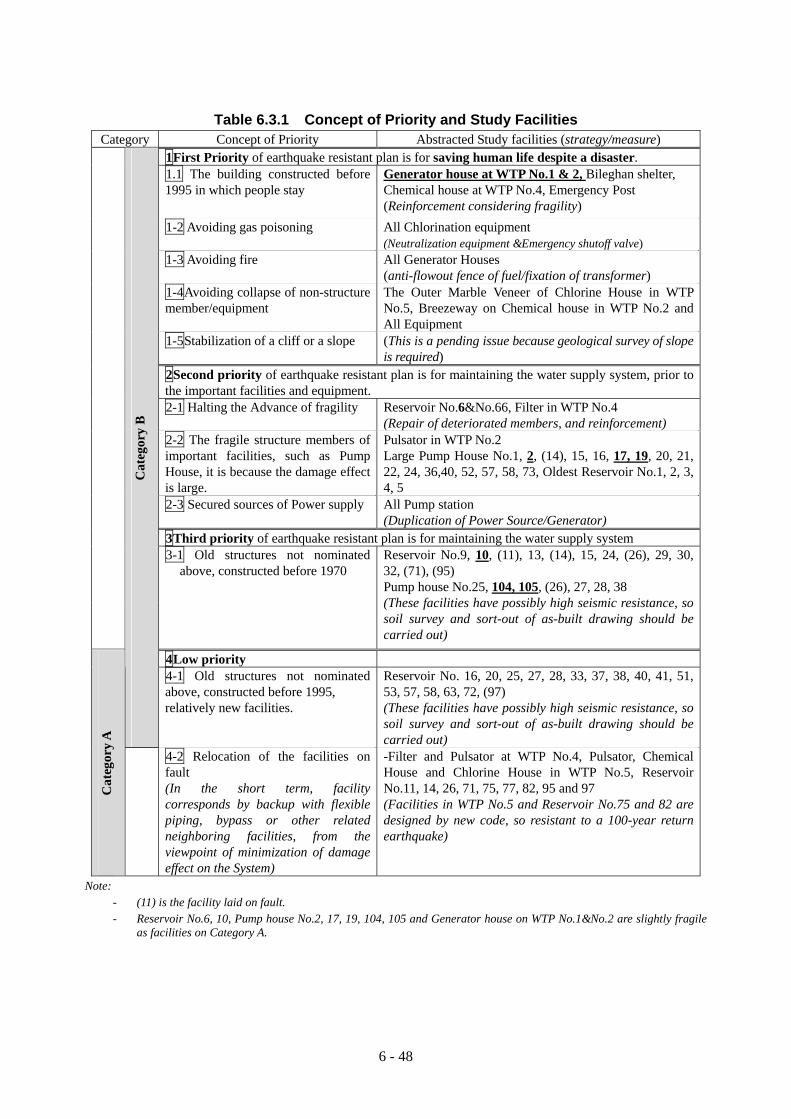
Table 6.3.1 Concept of Priority and Study Facilities Category Concept of Priority Abstracted Study facilities (strategy/measure) 1First Priority of earthquake resistant plan is for saving human life despite a disaster. 1.1 The building constructed before
1995 in which people stay
Generator house at WTP No.1 & 2, Bileghan shelter, Chemical house at WTP No.4, Emergency Post (Reinforcement considering fragility)
1-2 Avoiding gas poisoning All Chlorination equipment (Neutralization equipment &Emergency shutoff valve)
1-3 Avoiding fire All Generator Houses (anti-flowout fence of fuel/fixation of transformer)
1-4Avoiding collapse of non-structure member/equipment
The Outer Marble Veneer of Chlorine House in WTP No.5, Breezeway on Chemical house in WTP No.2 and All Equipment
1-5Stabilization of a cliff or a slope (This is a pending issue because geological survey of slope is required)
2Second priority of earthquake resistant plan is for maintaining the water supply system, prior to the important facilities and equipment.
2-1 Halting the Advance of fragility Reservoir No.6&No.66, Filter in WTP No.4 (Repair of deteriorated members, and reinforcement)
2-2 The fragile structure members of important facilities, such as Pump House, it is because the damage effect is large.
Pulsator in WTP No.2 Large Pump House No.1, 2, (14), 15, 16, 17, 19, 20, 21, 22, 24, 36,40, 52, 57, 58, 73, Oldest Reservoir No.1, 2, 3, 4, 5
2-3 Secured sources of Power supply All Pump station (Duplication of Power Source/Generator)
3Third priority of earthquake resistant plan is for maintaining the water supply system
3-1 Old structures not nominated above, constructed before 1970
Reservoir No.9, 10, (11), 13, (14), 15, 24, (26), 29, 30, 32, (71), (95) Pump house No.25, 104, 105, (26), 27, 28, 38 (These facilities have possibly high seismic resistance, so soil survey and sort-out of as-built drawing should be carried out)
4Low priority
Cat
egor
y B
4-1 Old structures not nominated above, constructed before 1995, relatively new facilities.
Reservoir No. 16, 20, 25, 27, 28, 33, 37, 38, 40, 41, 51, 53, 57, 58, 63, 72, (97) (These facilities have possibly high seismic resistance, so soil survey and sort-out of as-built drawing should be carried out)
Cat
egor
y A
4-2 Relocation of the facilities on fault (In the short term, facility corresponds by backup with flexible piping, bypass or other related neighboring facilities, from the viewpoint of minimization of damage effect on the System)
-Filter and Pulsator at WTP No.4, Pulsator, Chemical House and Chlorine House in WTP No.5, Reservoir No.11, 14, 26, 71, 75, 77, 82, 95 and 97 (Facilities in WTP No.5 and Reservoir No.75 and 82 are designed by new code, so resistant to a 100-year return earthquake)
Note: - (11) is the facility laid on fault. - Reservoir No.6, 10, Pump house No.2, 17, 19, 104, 105 and Generator house on WTP No.1&No.2 are slightly fragile
as facilities on Category A.

6 - 49
6.3.2 Measures for Minimization of Damage Occurrence (1) General
Study of measures for minimization of damage occurrence is a proper earthquake -resistant plan, and
some countermeasures would be based on structural analysis, the software/method of analysis is as
follows;
• For structural analysis the software, namely SAP 2000 ver.8, is applied. • Regarding the equipment study, there is no Iranian code for the method of strength analysis of
foundation bolt, so Japanese code was referred to, in the document titled “Seismic Design & Construction Guidelines for Building equipment (1997)” by the Building Center of Japan.
(2) Earthquake-resistant Plan on Tank 1) General and Present Situations
Study team has considered the following case study to define the problem clearly.
The selected structures for Study cases are Reservoir No.6 and Pulsator at WTP No.2, these are obviously fragile and have high priority, and structural analysis has been carried out by acceleration 0.35G.
For comparison, Structure of Reservoir No. 23 is analyzed in the case of biggest acceleration 0.691G on scenario earthquake of North Tehran Fault for reference.
Table 6.3.2 Present Earthquake Resistance Reservoir No.6 Pulsator
at WTP No.2 Reservoir No. 23
Construction Year 1955 1963 1970 Acceleration 0.35 0.35 0.35 0.691 Slab OK - OK NG Column OK - OK OK Wall (internal face) OK OK OK OK/NG* Wall (external face) NG NG OK OK/NG* Foundation OK OK OK OK
* On two-dimensional plan, short side of wall is safe, but long side of wall is not safe.
The result of analysis reflected that the estimated damage is not so disastrous on the basis of structural analysis, and required countermeasure would not be so large-scale.
On the basis of design acceleration 0.35, Reservoir No. 23 is safe, but small area of wall on Reservoir No.6 and Pulsator are slightly not safe due to hammering of active earth pressure during earthquakes.
Generally speaking, from the aspect of the ground condition, when it is extremely good, the ground which holds tank tightly, unifies with tank, so that the ground and tank move together in the case of occurrence of the earthquake, and the tank does not receive strong hits and damages.
Through the analysis, it is confirmed that the old tank located in southern area is slightly fragile but the relatively new tank located in northern area is strong against earthquake. This fact is the advantageous feature/good news regarding damage in the scenario earthquake of North Tehran Fault,
6 - 50
which should be considered as a priority in implementation program.
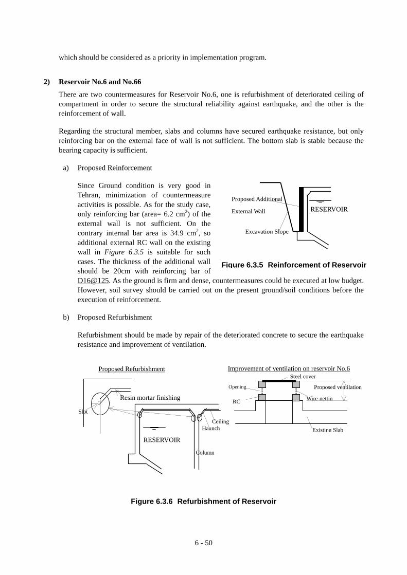
2) Reservoir No.6 and No.66
There are two countermeasures for Reservoir No.6, one is refurbishment of deteriorated ceiling of compartment in order to secure the structural reliability against earthquake, and the other is the reinforcement of wall.
Regarding the structural member, slabs and columns have secured earthquake resistance, but only reinforcing bar on the external face of wall is not sufficient. The bottom slab is stable because the bearing capacity is sufficient.
a) Proposed Reinforcement
Since Ground condition is very good in Tehran, minimization of countermeasure activities is possible. As for the study case, only reinforcing bar (area= 6.2 cm2) of the external wall is not sufficient. On the contrary internal bar area is 34.9 cm2, so additional external RC wall on the existing wall in Figure 6.3.5 is suitable for such cases. The thickness of the additional wall should be 20cm with reinforcing bar of D16@125. As the ground is firm and dense, countermeasures could be executed at low budget. However, soil survey should be carried out on the present ground/soil conditions before the execution of reinforcement.
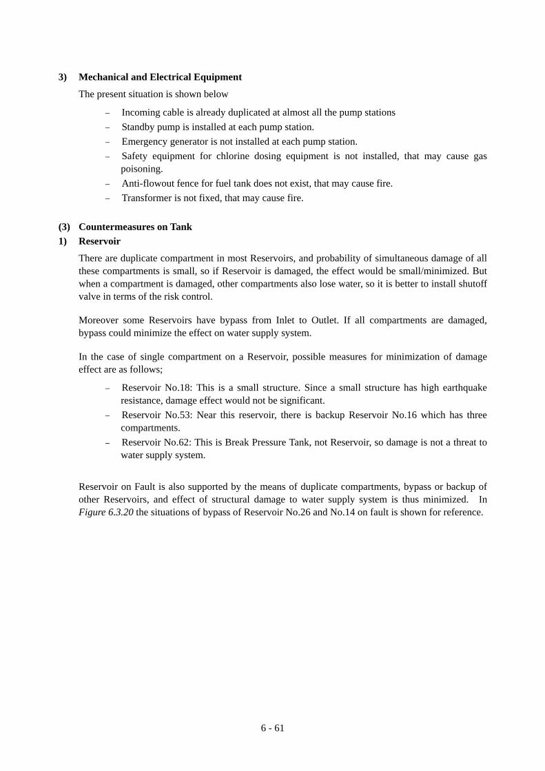
b) Proposed Refurbishment
Refurbishment should be made by repair of the deteriorated concrete to secure the earthquake resistance and improvement of ventilation.
Figure 6.3.6 Refurbishment of Reservoir
Figure 6.3.5 Reinforcement of Reservoir
Proposed Additional
External Wall RESERVOIR
Excavation Slope
Proposed ventilation
Improvement of ventilation on reservoir No.6 Steel cover
Wire-nettin
Existing Slab
RC
Opening
Haunch
Resin mortar finishing
Ceiling
RESERVOIR
Column
Slot
Proposed Refurbishment

6 - 51
Deterioration of inside compartment due to insufficient ventilation was observed in Reservoirs No.6 and No.66. Before refurbishment of that, thorough investigation (the number of exposed bar) is required. Design for refurbishment at haunch and ceiling of Reservoir No.6 would be proposed just for reference.
Generally, execution procedures for refurbishment is as follows
− Stripping the deteriorated concrete off by high pressure washing − Rust resisting paint application for corroded reinforcing bar / attached bar − A slot is cut to concrete in the edge of finishing. − Primer application − Three times as much of resin mortar finishing by Trowel finish for 2 cm concrete cover − Improvement of ventilation
3) Oldest Reservoirs
For the cases of the oldest Reservoirs from No.1 to No.5, the conditions of which were explained in the previous general clause, their wall might be reinforced in the same manner as the proposal of additional external wall for Reservoir No.6.
Though we consider these countermeasures in implementation program, we anticipate TWWC to carry out further study including the soil survey, preparing the present drawings of bar arrangement and structural analysis, as soon as possible.
4) Other Reservoirs
On the basis of DTSC, Reservoir in deep-water or semi-buried is assumed middle rank in terms of earthquake resistance.
We could not specifically evaluate the seismic resistance, because it was difficult to survey all tank’s bar arrangements and to grasp the tendency of bar arrangement. So we anticipate TWWC to carry out further study, which shall include the soil survey, preparation of the present drawings of bar arrangement and structural analysis in near future, after the measures are implemented in the oldest Reservoirs.
We will consider these situations in implementation program.
5) Tank of WTP
Generally speaking, circular sedimentation tank or rectangular tank with a depth of 3m or less has high earthquake resistance, but Pulsator’s wall in WTP No.2 is not only deep but also thin (25cm). Therefore, the deepest part of the wall which experiences active earth pressure during earthquakes, has led to insufficiency of wall thickness/reinforcing bar.
On the other hand Pulsator in WTP No.3 and No.4 are of the same water depth as No.2, but the wall is 40cm thicker than No.2, so were analyzed as safe.
Therefore reinforcement of Pulsator in WTP No.2 is only proposed.
Moreover, improvement of leakage condition in Filter in WTP No.4 is required; the problem is small in present situation but is very much likely to grow to alarming level in forthcoming earthquake, so countermeasure would be proposed.

6 - 52
a) WTP No.2 Pulsator
Small area of wall and foundation of Pulsator should be reinforced as shown in Figure 6.3.7.
When the reinforcement is carried out, it would be better to fix the trough for water catchments together.
Figure 6.3.7 Reinforcement of Pulsator
b) Filter at WTP No.4
Regarding leakage of water from the Filter at WTP No.4, it might lead to a big problem in response to an earthquake.
While the problem is small now, it should be solved to secure functions in case of occurrence of the earthquake.
Since the foundation of structure is already stabilized and there are many expansion joints compared with the other WTP, the removal of a part of Expansion Joint and the unification of a part of structures of the basement in Filter house would be proposed.
Figure 6.3.9 Improvement of Leakage on Filter
Figure 6.3.8 Section of Filter
Procedure of Construction
1 Excavation
2 Proposed RC Wall
3 Back filling
Top Slab
1
2
PULSATOR
Foundation
Wall Excavation Slope
Existing Buttress
Filter H ouse
F ilter F ilter leakage
Water leakage
Fillet welding
Existing Reinforcing bar Attached Reinforcing bar
Cut off and Interfiling non shrinkage mortal Present leakage situation Detail section of repair

6 - 53
(3) Earthquake-resistant Plan for Buildings
The priority of countermeasure for the buildings where people reside for routine work is higher than tank,
and reinforcement for building is relatively easy to implement and at affordable construction cost, so in
Japan the reinforcement of almost all of the public buildings have been finished in a short time after the
regulation was enforced.
Therefore, in Tehran also reinforcement of buildings should be implemented in a short time.
1) Reinforcement method on buildings of RC structure
In Japan there are many reinforcement methods as described in Table 6.3.3 under Japanese special circumstances. On the other hand the premises in Tehran water supply facilities afford to be constructed by any method, so Shear Wall of RC method by cast in place is adopted because of its low construction cost.
Though other alternative is Brace method, Iranian method of reinforcing wall is filling by use of brick into vacancy, as we intend to reinforce brick wall simultaneously, RC wall is suitable for our intention.
2) Pump House
Installation of Shear Wall and Reinforcement of brick wall for Pump House are as follows
− The fragile member is reinforced by RC shear wall with the aim of reducing horizontal deformation. As a consequence, deformation of frame is restricted and the risk of collapse of brick wall would be reduced.
− Since it was manifested in Bam earthquake that the brick wall without tie attachment (Figure 6.3.12) would collapse, tie is essential on masonry for securing shear strength. If the brick wall of target building is not installed with tie, wall should be fixed somehow. So fixation of brick wall to clip by steel plate, as shown in Figure 6.3.11, would be proposed. (also refer to Figure 6.3.13 )
Figure 6.3.10 Plan of Arrangement of Shear Wall Figure 6.3.11 Fixation of Brick Wall
P L - 6 , L - 1 0 0 * 5 0
G IR D E R
O P E N N IN G
B O L T (w 3 /8 )
1 F L
( W IN D O W )
P L - 6 * 1 0 0
100
G F L
B R IC K W A L L
S E C T IO N
Shear Wall

6 - 54
Figure 6.3.12 Tie Attachment 3) Emergency Post
As requested, supplementary survey of Emergency Post was performed for preparation of earthquake-resistant plan.
There are 18 Emergency Posts that are important for emergency repair on earthquake. Five Posts had been surveyed; they are four Masonry Houses (Zargandeh, Niavaran, Amir Abad, Reservoir 54) and one Steel Structure House (Shahrake Gharb).
Masonry Houses, Earthquake resistance capacity of which could not be evaluated, are currently occupied by so many workers, so they should be reinforced in the manner of the proposed idea as shown in Figure 6.3.13.
Steel Structure House would not intensively collapse, so could be renewed in the future.
It is not because of RC Structure, but size of the building might be smaller than Chemical House at WTP No.4. Chemical House at WTP No.4 has earthquake resistance without shear wall, so earthquake resistance of Emergency Post Shahrake Gharb would be secured.
Figure 6.3.13 Fixation of Brick Wall and Reinforcement of Masonry House
tie attachment
brick
Brick Wall
Steel Plate
Fixation of Brick Wall Reinforcement at Corner of Masonry House (plan)
Window/Door
Brick Wall
Reinforcement by Steel Plate
Corner
Room

6 - 55
Table 6.3.3 Reinforcement Methods in Japan
Note: As this table which has been created on actual design and commonly used in Japan, was translated as a sample in this study, there might be possibility that some of the above methods could not be applied to any case in Iran.
P R E S T R E S S E D - C O N C R E T EM E M B E R
PR OOF
STR E N G THwall ○ column ○ ○
P R O O F
S TR EN GTH &
TO U GH N ES Swall ○ column - ○
T OU G H N E SS wall - column ○ -BE A M -WA L L ○
C O L U M N -SL A B -
H A U N C H -
FE A T U R E
A D V A N T A G E
M E T H O D
F I G U R E
B R I E F I N G O F M E T H O DF O R R E I N F O R C E M E N T
C A R B O N F I B E R S H E E T R E I N F O R C E M E N T
○
○
○
○
○
-
-
APPLIC ATIO N
○
○
○
○
○
CAS T I N P L A C E
R C M E T H O D
○
■Most commonly used method■Long construction periodrequires and a work environmentis not so good for worker.■Skill requires for anchoring of amain re inforcement.
The rebarring work of a mainre in forcement and the shearre in forcement on the arroundof the existing column iscarried out , and improvesresistance to stress anddeformation .
The small precast unit which usedlightwe ight concrete (about 1 .3specific gravity) is manufactured and isinstalled inside of the building.A precast unit is installed by a requiredanchor and a rebarring work, and aopen ing is filled up shrinkage-compensating mortar into it .
■Site operation is easy andconstruction period is shortened.
The carbon fiber which is excellent in a light weight and corro sionresistance, is stuck on the existing member face, and re inforce smember with h igh intensity, specifically increase in the shearstrength of a column or a beam component and improvement indeformation resistance nature are achieved.
Execution procedures:1. Surface treatment on the surface of concrete2. Primer application3. Adhesive-bond(resin) application4. Attachment of a carbon fiber5 . Resin application6. Fin ish ing (the material of construction is chosen if needed)
■There is almost no increase in a weight or a size afterre inforcement.■Since the material is light, handling is easy and a constructionperiod is shortened.■It is su itable also under corrosive atmosphere , such as saltdamage, for the incorruptible material.
○ ○ △
○ ○ △
- ○ △
- - ○
○ ○ ○
- - ○
- - ○
- -
CAS T - I N - P L A C EP R E S T R E S S E D C O N C R E T E
E X T E R N A L F R A M EB R A C E
■A problem arises in steel framefabrication and on-site carrying-in /anchoring accuracy.■A construction period is early ifthe above problems do not occur.
Steel frame brace with a frame(stud) is installed and fixed byanchor on the existingcolumn&beam .Regarding installation , afterattaching a spiral re inforc ing baron the arround of a brace,shrinkage-compensating mortar ispoured in a open ing.
PC steel is inserted into thehole of existing member whichis drilling in advance.Since improvement in axialtension can be aimed at,increase in a shear and flexuralstrength and improvement indeformation resistance natureare expectable .This is applicable forundergroung chamber/tank.
■Since PC steel is insertedfrom the outside , function ofchamber/tank is retained.
PC鋼棒柱
底盤
Additinal new RC structuralframe is installed outside ofexsisting structural frame.
Execution procedures:1.Anchoring on the exteriorface of existing column&beam .2 .Plac ing of re inforcement3.Formwork4.Concreting in flu id andlightweight aggregateconcrete
■Since it is constructed atoutside of a building, indoorroutine work is possible .
PCCOLUMN
BOTOMN SLAB
6 - 55

6 - 56
4) Generator House
Shear wall in Generator Houses of WTP No.1 & No.2 would be proposed, same as in case of Pump House, refer to Figure 6.3.10.
The fragile member of Generator Houses at WTP No.1 & No.2 should be reinforced by RC shear wall to reduce horizontal deformation. As a consequence, shear strength should be improved, deformation of frame is restricted, the risk of collapse of brick wall should be reduced and mitigation of fire should be provided for.
5) Breezeway
End Support of Breezeway in Chemical house in WTP No.2 would be proposed.
Bar arrangement drawing of Breezeway could not be found out, but the end of Breezeway would be acted upon by twisting moment of structure, so end supports of Breezeway on both sides would be required to prevent falling.
Figure 6.3.14 End Supports of Breezeway 6) Bileghan Intake Shelter
There is a defensive wall on the south face of shelter, but not on the north face. When the cliff collapses, the rocks will block entrance or might damage resting place, which might lead to an accident resulting in injury or death. Therefore, RC wall should be constructed on the north face of the shelter.
7) Chemical Factory
Since detail drawing could not be found out, structure analysis was suspended. If this building would be used somehow, large-scale refurbishment would be required as follows;
− Rust resisting paint application for corroded steel, which composes principal members, should be made.
− Reinforcement by bracing the principal members of structure should be made.
2 3 4
2500
4750
250
850030003300
400
800
800
400
Brick Wall
Reinforced Concrete Wall
FRAME PLAN S=1/100
W25 W25 W25
GL GFL
W30
1FL
1
1FL
1000
End Support

6 - 57
− Roof, external wall, floor, internal wall and fixtures/furniture should be installed/replaced by new materials, roof should be installed by lightweight materials and setting heat insulating materials.
Figure 6.3.15 Defensive Wall on Bileghan Shelter (3) Earthquake-resistant Plan on Mechanical and Electrical Equipment
Main typical equipment such as Pump is installed firmly, but fixation of sub-equipment is not so good.
Therefore, as countermeasures for minimization of damage occurrence on equipment, such as fixing the
equipment (chlorine cylinder, transformer, battery, UPS, 400V pump panel, etc) and installation of pipe or
cable with flexibility and support for surge tank, should be implemented.
1) Support for Surge Tank
This countermeasure is proposed for Reservoirs No.2, No.22, No.96. Figure 6.3.16 shows countermeasure plan at Reservoir No.22. Countermeasure for Reservoir No.2 is reported in the Appendix.
3300 3300 3000
700
1000
4000
9600
5700
W25W50
W50
B
GL 400GL 0+- +-
OPERATORROOM
GROUND FLOOR PLAN S=1/100
W20
4000 1000 700
2000
500 5700 350
X'
X
2700
450
3600
GL
W20
FLAME ELEVATION S=1/50 X - SECTION
(CLIFF)
A
1 2 3 4
B A 1
450
Proposed defensive wall
Cliff

6 - 58
Figure 6.3.16 Countermeasure at Reservoir No.22 2) Fixation of Chlorine Cylinder
This countermeasure is proposed for WTPs No.1, No.2, No.3, and all the chlorine dosing stations. Figure 6.3.17 shows proposed countermeasure at typical WTP and chlorine dosing station.
Figure 6.3.17 Countermeasure at Typical WTP and Chlorine Dosing Station 3) Fixation of Transformer, Battery, UPS, 400V Pump Panel
This countermeasure is proposed for almost all the WTPs and pump stations. Figure 6.3.18 shows the method of measure taken for typical transformer. Other countermeasures are reported in the Appendix. Steel stage of Pump Panel at Station No.72 looks fragile, so brace of column would be proposed in the Appendix.

6 - 59
Figure 6.3.18 Countermeasure for Typical Transformer 4) Installation of Flexible Pipe
To equip fuel feeding pipe with flexibility, it is necessary to install flexible pipe on generator equipment. Figure 6.3.19 shows proposed countermeasure at typical generator equipment. Other countermeasures are also described in the Appendix.
Figure 6.3.19 Typical Countermeasure of Fuel Feeding Pipe
6.3.3 Measures for Minimization of Damage Effect
(1) Outlook of Minimization of Damage Effect of the System or Secondary Disasters • Avoiding the secondary disasters, which is an objective of Minimization of damage effect on
facilities structure and equipment, would be provided for by the proposed countermeasures. • Multiple compartments or bypass of inlet to outlet on Reservoir would help to reduce the damage
effect on water supply system. • Duplicate channel on WTP would be evaluated with the viewpoint of minimization of damage
effect to water supply system. • Structural reinforcement of Pump house or Building, which is an architectural structure, should be
able to be measured with the viewpoint of minimization of damage occurrence, and it has also additional objective of minimization of damage effect, because the structural damage might lead to physical injury.
• Fixation of non-structural members such as degraded windowpane or outer wall finishing material
Generator

6 - 60
mitigates physical injury. Therefore, improvement of safety of non-structural member should be studied here.
• Regarding Mechanical and Electrical Equipment, Standby Pump or Duplication of Power Source would be evaluated from the aspect of minimization of damage effect to water supply system.
• Fire, gas poisoning or loss of human life would occur at the location of high-risk facilities: generators, transformers, chlorine dosing equipment and facilities on the cliff. On the measures and implementations of these facilities, study team prepared Secondary Disaster Map shown in Figure 6.3.3, intended to mitigate these risks.
• Facilities on Fault should be relocated in the future, but should correspond by the means from the aspect of minimization of damage effect to water supply system.
(2) Present situations on Minimization of Damage Effect 1) Tank
a) Reservoir
Main Reservoirs are installed with duplicate compartments as shown in the plan of Reservoirs in a report named “Report of Available condition of Tehran Water Network Appendix 3” In this report plans of forty six Reservoirs are available. Moreover many Reservoirs shown in this report have bypass from Inlet to Outlet.
Table 6.3.4 Number of Compartment in Reservoir Reservoir
name Compartment
No. Reservoir
name Compartment
No. Reservoir
name Compartment
No. No.1 4 No.18 1 No.36 3No.2 2 No.19 2 No.37 2No.3 3 No.20 2 No.38 2No.4 3 No.21 3 No.40 2No.5 3 No.22 4 No.41 2No.6 3 No.23 3 No.51 2No.7 3 No.24 4 No.53 1No.8 3 No.25 2 No.56 3No.9 2 No.26 4 No.57 2
No.10 2 No.27 2 No.58 2No.11 2 No.28 2 No.62 1No.12 2 No.29 2 No.63 2No.13 3 No.30 3 No.89 2No.14 3 No.31 3 No.73 4No.15 4 No.32 2 No.17 No ReservoirNo.16 3 No.34 2
Reservoir No.11, 14 and 26 are on Fault.
b) Tank of WTP
Treatment tank is divided into duplicate tanks. Inlet channel is one or two lines for one treatment plant.
2) Building
Nonstructural members such as windowpane or marble veneer are deteriorated, and might lead to death or injury of human beings.
6 - 61
3) Mechanical and Electrical Equipment
The present situation is shown below
− Incoming cable is already duplicated at almost all the pump stations − Standby pump is installed at each pump station. − Emergency generator is not installed at each pump station. − Safety equipment for chlorine dosing equipment is not installed, that may cause gas
poisoning. − Anti-flowout fence for fuel tank does not exist, that may cause fire. − Transformer is not fixed, that may cause fire.
(3) Countermeasures on Tank 1) Reservoir
There are duplicate compartment in most Reservoirs, and probability of simultaneous damage of all these compartments is small, so if Reservoir is damaged, the effect would be small/minimized. But when a compartment is damaged, other compartments also lose water, so it is better to install shutoff valve in terms of the risk control.
Moreover some Reservoirs have bypass from Inlet to Outlet. If all compartments are damaged, bypass could minimize the effect on water supply system.
In the case of single compartment on a Reservoir, possible measures for minimization of damage effect are as follows;
− Reservoir No.18: This is a small structure. Since a small structure has high earthquake resistance, damage effect would not be significant.
− Reservoir No.53: Near this reservoir, there is backup Reservoir No.16 which has three compartments.
− Reservoir No.62: This is Break Pressure Tank, not Reservoir, so damage is not a threat to water supply system.
Reservoir on Fault is also supported by the means of duplicate compartments, bypass or backup of other Reservoirs, and effect of structural damage to water supply system is thus minimized. In Figure 6.3.20 the situations of bypass of Reservoir No.26 and No.14 on fault is shown for reference.
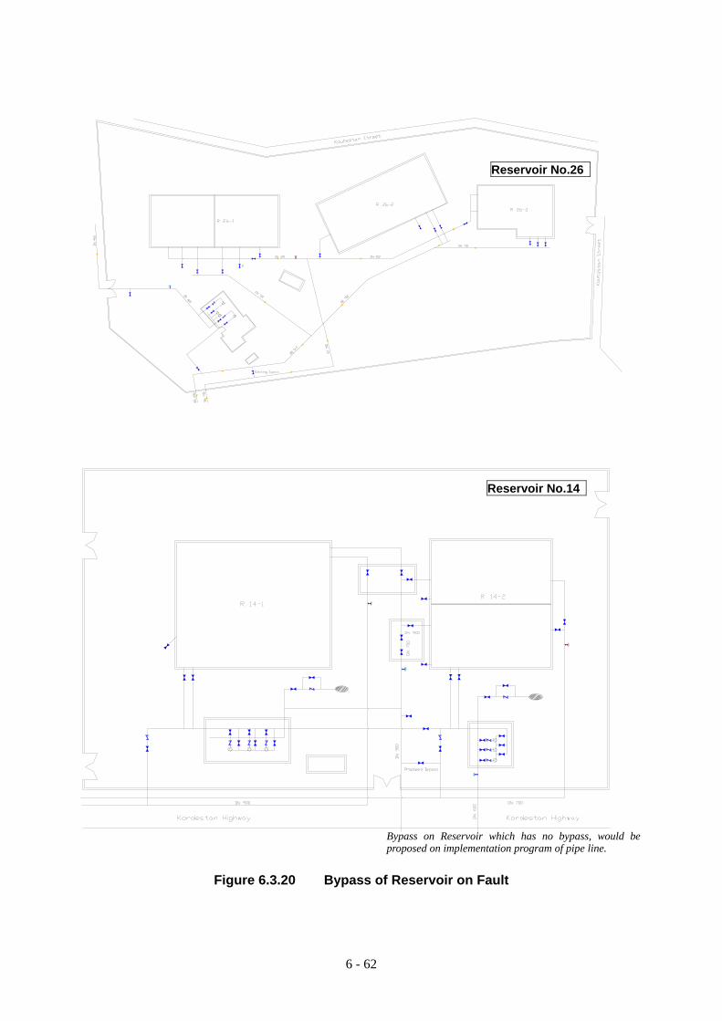
6 - 62
Figure 6.3.20 Bypass of Reservoir on Fault
Reservoir No.26
Bypass on Reservoir which has no bypass, would be proposed on implementation program of pipe line.
Reservoir No.14

6 - 63
2) WTP
Treatment tanks are divided into several tanks, so damage effect would be mitigated. If inlet channel has duplicate line, damage effect would be further minimized.
− WTP No.1: Only one inlet channel is placed from inlet chamber to Accelerator, inlet channel’s water level is high, which means no margin. So one more line is desired, but there is no space for line construction. However, space for bypass line from inlet chamber to filter should be secured, if possible in terms of water quality, so that bypass would be effective.
− WTP No.2: Treatment Plant is divided into two, so damage effect would be mitigated. − WTP No.3, No.4: Two lines are secured including both treatment plants, so damage effect
would be mitigated. − WTP No.5: If half of the plant would be expanded, damage effect would be mitigated.
(3) Countermeasures on Building 1) Window
Windowpane would crash and fall down due to degraded cushion (face putty or cap sealant) of windowpane. Therefore, if possible, it’s better to replace the window including the frame.
At least, shatter-resistant film should be pasted on windowpane in order to mitigate risk of glass breakage, scattering and injuring human life.
2) Door
Sliding hanger door for outer door is adopted as an earthquake-resistant measure, considered better than swinging door.
On the other hand for inner door, wooden swinging door is adequate because when people are trapped inside, it could be broken and people can escape.
3) Outer Wall Finishing
As pointed out in the chapter on reconnaissance already, heavy outer wall finishing material such as marble veneer could cause injury or death. Installation of large marble veneer to columns is not stable in chlorine house in WTP No.5. Since marble veneer has already fallen down, and installation position is high, it is dangerous in case of earthquake. There are two alternatives: one is to strip off all of them and re-install with small anchor bolts, another is to fix them by anchor bolts on veneer. Second method is recommended because it is easy and more secure.
(4) Mechanical and Electrical Equipment
At present, incoming cable is already duplicated at almost all the pump stations, and standby pump is
installed at each pump station to minimize the damage effect. So minimization of the damage effect is
approximately fulfilled.
However, emergency generator is not installed at each pump station. When power supply is interrupted,
operation of pump has to be stopped. Moreover, safety equipment for chlorine dosing equipment is not
installed, and anti-flowout fence for fuel tank is not constructed, that may cause secondary disaster.

6 - 64
So, the Duplication of Power Source on Pump station for securing the reliability of power supply,
possibility of Generator’s introduction, safety equipment for chlorine dosing equipment and anti-flowout
fence for fuel tank have been studied.
1) Duplication of Power Source
Figure 6.3.21 shows countermeasures for duplicating power source at a typical pump station. a) is a countermeasure by installment of emergency generator, b) is a countermeasure by duplicating incoming cable. a) is a more reliable system but construction cost is very high. (See Appendix).
In addition, Generator for Pump station is actually huge, requires vast area for arrangement, and less working ratio (once a 100-year), also regular maintenance is necessary once a month. Therefore countermeasure a) is considered as not realistic. So in the future when renewal of facility would be coming, installation of Generator ought to be studied.
Figure 6.3.21 Countermeasure for Duplicating Power Source at Typical Pumping Station
a. Installation of Emergency Generator
b. Duplication of Incoming Cable

6 - 65
2) Mitigation of Secondary Disaster
Figure 6.3.22 shows countermeasure plan against oil leakage at WTP No.1. If oil leaks out from the fuel tank by the damage due to earthquake, fuel is stored in the anti-flowout fence, and risk of fire would diminish.
Figure 6.3.23 shows basic flow diagram of on-site generation of sodium hypochlorite system.
In Japan, liquefied chlorine gas was mainly used in 1950’s-60’s. On the other hand, sodium hypochlorite system began to be adopted in the middle and small scale water supply facilities around 1975. Sodium hypochlorite system also has been adopted in the large scale water supply facilities these days, due to growing number of residence adjoining water supply facilities, technology improvement, and preparation of supply organization aimed at mass consumers.
Figure 6.3.24 shows basic flow diagram of neutralization equipment to diminish gas poisoning. This system is generally composed of a caustic soda storage tank, an absorption tower, a chemical pump, and a blower. The blower draws contaminated air by chlorine gas through a suction duct from the house, and conveys the gas to the absorption tower. While the caustic soda pump supplies caustic soda solution to the upper part of the absorption tower, the resultant neutral gas will be discharged into the air.
In addition to neutralization equipment, gas shutoff valve is also effective to prevent secondary disasters.
Figure 6.3.22 Anti-flowout Fence at WTP No.1
Figure 6.3.23 Basic Flow Diagram of On-site Generation of Sodium Hypochlorite System
PLAN SECTION
Fuel tank (existing)
Anti-flowout Fence

6 - 66
Figure 6.3.24 Flow Diagram of Neutralization Equipment

6 - 67
6.3.4 Look-over the Proposed Countermeasures in Terms of Risk Control
The previously proposed countermeasure should be confirmed on Inventory of Risk& Countermeasures
(Table 6.3.5) in terms of response to the possible risks that consist of experience in Japan and Iranian
concerns based on Brainstorming. This process must be carried out to keep away an error on oversight of
countermeasures.
Table 6.3.5 has a function of a Checklist to make the previously proposed earthquake-resistant measures
checked in this table regarding the following;
• Proposed measures are categorized as feasible Implementation Plan and ideal Future Plan. • Pending issue required further survey is confirmed based on the reason of pending, such as
stabilization of slope, described the reason of requiring geological survey in a table. • Non-application measures are confirmed.
If there is an oversight on measures, study would be fed back to site survey, DTSC and selection of target
facilities as described in previous section 4, and countermeasure would be studied again. In this study,
possible countermeasures are checked based on the present conditions.
Table 6.3.5 Risk Control Chart (check sheet of measures) I Implementation Plan
F Future plan
P Pending issue “Reason of Pending”
N Non-application (general countermeasure)
Risk Check of the Countermeasures
S-1 Risk on Ground conditions
F
S-1-1-1-a Replacement (shifting of location and re-construction): (Reservoir No.11, 14, 20, 26, 75, 77, 82, Chlorine house, chemical house and Pulsator at WTP No.5, Pulsator and Filter at WTP No.4, Reservoir at WTP No.3&4(No.71,95,97) Construction finance is not involved in Earthquake-resistant plan.
S-1-1-1 Fault shifts causes great damage to structures and subsequently accidents resulting in injury or death
IS-1-1-1-b Back up by other function Reservoir No.11, 14, 20, 26, 75, 77, 82, Chlorine house, chemical house and Pulsator at WTP No.5, Pulsator and Filter at WTP No.4, Reservoir No.71,95,97 at WTP No.3&4
S-1-1-2-a Ground-improvement method S-1-1-2-b Piling or sheeting for ground transfer prevention
S-1-1-2 A soft-ground soil slides and differential settlement occurs and the structure inclines, or crack in concrete leads to water leakage
P“Required geological survey of slope at ReservoirNo.68, 89” S-1-1-3-a Ground-improvement method
N S-1-1-3-b Ground-water fall method S-1-1-3 Liquefaction occurs and differential settlement occurs and structure inclines, or crack of concrete causes water leakage
S-1-1-3-c Ground-water interception sheeting

6 - 68
S-1-1-4-a Falling-stone prevention wall, Retaining Wall
S-1-1-4-b Concrete spraying on slope S-1-1-4-c A forestation on slope S-1-1-4-d Ground anchor retaining on cliff S-1-1-4-e Ground-improvement method on slop/cliff
P
“Required geological survey at Reservoir No.26, 28, and Bileghan Intake”
S-1-1-4 A cliff collapses and damages the building.
I S-1-1-4-f Construction of defensive wall on building Bileghan Shelter
S-1-1-5-a Ground-improvement method S-1-1- Landfill collapses or exposed foundation causes differential settlement.
N S-1-1-5-b Slope stability method (S-1-1-4-b, S-1-1-4-c)
S-1-1-6-a Ground-improvement method “Required geological survey of southern premises of Reservoir No.55 and eastern premises of Reservoir No.25 for private residence”
S-1-1-6 A slope collapses and damages the facilities, private residence, or road
PS-1-1-6-b Slope stability method (S-1-1-4-b, S-1-1-4-c)“Required geological survey at Reservoir No.38 for road, No.23 and No. 91 for telemetry building placed by the slope”
S-2 Risk on Structural members
S-2-1-1-a Frame reinforcement by steel brace S-2-1-1 Column collapses, and beam and roof deform or fall.
I
S-2-1-1-b Frame reinforcement by RC shear wall Generator house at WTP No.1, Generator house at WTP No.2, Pumping houses No.1, 2, 15, 16, 17, 19, 20, 22, 24, 36,40, 52, 57, 58, 73,27, 28, 38
S-2-1-1-c Reinforcement by carbon fiber sheet
N S-2-1-1-d Cross-sectional partial reinforcement by steel plate
S-2-1-2 Crack occurs at the tank, causes water leakage and water is contaminated.
I
S-2-1-2-a Reinforcement of partial member Pulsator on WTP No.2 Oldest Reservoir No.1, 2, 3, 4, 5, 6 Old Reservoir No.9, 10, 11, 13, 15, 16, 20, 23, 25, 29, 30, 32 (These are target facilities, but further soil survey is required)
F
S-2-1-2-a Reinforcement of partial member (relativelynew) Reservoir No.24, 27, 28, 33, 37, 38, 40, 41, 51, 53, 57, 58, 63, 72 “further soil survey is required.”
S-2-1-2-b Installation of slab and transmits horizontal force to wall
N S-2-1-3-a Addition of water-stop S-2-1-3 When whole structure deforms, a deformation becomes the maximum by Expansion Joint, so water stop is cut and water leaks.
IS-2-1-3-b Abolishment of the effectiveness of ExpansionJoint and unification of a part of structure Filer at WTP No.4
S-2-2-1 As the structure is complicated, S-2-2-1-a Ground-improvement method
6 - 69
I S-2-2-1-b Fixation of Breezeway WTP No.4 chemical house
when structural model is not optimal, the inestimable force acts, which causes the increase of load on some members, and deformation.
S-2-2-1-c Support of cantilever structure
S-2-2-2-a Ground-improvement method S-2-2-2 If the foundation is bad toppling of Over Head Reservoir causes a second disaster on the outskirts.
P S-2-2-2-b Extension of foundation width “Required geological survey of elevated tank’s foundation at Reservoir at No.68”
S-2-3-1 When there is large degradation which the bar has exposed, as the structural function is lost and earthquakeresistance cannot be expected, buckling, deformation, crack, leakage of water, etc. occur.
I
S-2-3-1-a Repair (Refurbishment) Reservoir No.6, 66
S-3 Risk on Non-structural members
F S-3-1-1-a Extension of support bearing length
S-3-1-1-b Stopper
S-3-1-1 The trough of Pulsator gets separated or breaks down and water quality deteriorates. I Pulsator’s trough in WTP No.2 is reinforced together
with the wall
I S-3-2-1-a Reinforcement of brick wall Building of WTP, Pump House and Emergency Post
S-3-2-1 The brick wall collapses and causes an accident resulting in injury or death, or equipment is damaged. N S-3-2-1-b Replacement with an alternate light material
S-3-3-1-a Replacement with the degraded window and frame. (common countermeasure)
S-3-3-1 Windowpane breaks because of caulking material degradation which cancause an accident resulting in injury or death.
IS-3-3-1-b Shatter-resistant film should be pasted on windowpane (common countermeasure)
S-3-3 –2 Broken door prevents a man to escape I S-3-3 – 2-a Replacement with the degraded door and
frame. (common countermeasure)
I S-3-4 -1-a Fixation with anchor bolt The outer Marble Veneer of chlorine house of WTP No.5
S-3-4-1 The outer Marble Veneer falls, which causes an accident resulting in injury or death.
N S-3-4 -1-b Re-work
S-3-5-1 same as S-2-1-3 N S-3-5-1-a Installation of a water stop with big displacement S-3-6-1-a Backfilling-improvement S-3-6-1-b Foundation Soil-improvement S-3-6-1-c Fixation with Earth anchor
S-3-6-1 A Retaining Wall topples and a building slides, and this causes an accident resulting in injury or death. P
S-3-6-1-d Fixation with Tieback pile “ Required geological survey of Retaining wall of chemical house at WTP No.5”
I S-2-7-1-a Fixation of handrail post (common countermeasure)
S-3-7-1 A man may fall over handrail resulting in injury or death.
I S-2-7-1-b Replacement of the high handrail (common countermeasure)
E-1 Risk on Main Equipments
I E-1-1-1-a Fixation with foundation bolt E-1-1-1 Overturn of surge tank leads to failure of pumping. I E-1-1-1-b Installation of additional support
Pump station No.2, 22, 96

6 - 70
IE-1-1-2-a Installation of stable pedestal Bileghan, WTP No.1 to No.3, and Stations No. 1, 2, 13, 14, 15, 16, 17, 19, 20, 21, 22, 24, 25, 26, 40, 52, 56, 57, 58, 65, 68, 73, 114
I
E-1-1-2-b Installation of neutralization equipment and emergency shutoff valve Bileghan Intake, WTP No.1 to 5, Stations No.52, 73, 4, 5, 7, 13, 19, 21, 31, 36, 40, 65, 66, 68, 69, 89, Southern Tarasht, Said Abad
F E-1-1-2-c Replacement of the chlorine dosing system with safer systems such as sodium hypo chlorite system.
N E-1-1-2-d Re-piping copper chlorine tube with enough spare length
E-1-1-2 Gas leakage from chlorine cylinder causes an accident resulting in injury or death.
NE-1-1-2-e Reinforcement the brick wall to the RC wall which the copper chlorine tube pass through. (belong to non-sructure member)
E-1-1-3 Overturn or sideslip of transformer causes failure of the water supply and fire.
IE-1-1-3-a Fixation with foundation bolt in addition to stopper All transformers
IE-1-1-4-a Fixation with foundation bolt pump station No.8, 12, 13, 27, 28, 32, 34, 36, 37, 38, 43, 59, 65, 66, 68, 69, 71, 72, 74, 75, 80, 81, 90, 91, 93, 95, 96, 101, 102, 105, Well Pump
E-1-1-4 Overturn of electrical panel causes operating failure of the water supply.
IE-1-1-4-b Reinforcing of stage Reinforcement of steel stage at Pump station No.72, would include the countermeasure of fixation of panel.
E-1-1-5-a Fixation with foundation bolt E-1-1-5 Overturn of pump causes operating failure of the water supply. N
E-1-1-5-b Installation of stand by Pump
I E-1-2-1-a Installation of flexible pipe WTP No.1 to No.5, Bileghan Intake
E-1-2-1 Damage to pipe causes leakage of water, failure of water supply, and failure of emergency water supply.
IE-1-2-1-b Installation of emergency shut-off valve at outlet of reservoir All Reservoir (Section 6.1)
E-1-2-2 Damage to cable causes operating failure of the water supply. N
E-1-2-2-a Rewiring of cable for the important equipment with enough spare length.
E-1-2-3 Leakage of fuel for emergency generator causes secondary disaster like fire
IE-1-2-3-a Construction of anti-flowout fence Generator in Bileghan Intake GeneratorWTP No.1 to No.5
E-1-2-4 Toppling of electric post causes power failure. I E-1-2-4-a Installation of stay.
Reservoir No.22
E-1-2-5 A man between huge piping couldn't escape and falls a victim in the pump room.
NE-1-2-5-a Installation of stages over piping
F E-1-3-1-a Installation of emergency generator E-1-3-1 (Blackout ) Failure of water supply, or deterioration of water quality
I E-1-3-1-b Duplicate Incoming Cable Pump Station No.16, 52, 68, 114
E-1-4-1 (Reliability of equipment) Equipment breaks down and does not N E-1-4-1-a replacement

6 - 71
work or a glitch occurs. E-1-5-1 (Information) As broadcast does not inform the earthquake intensity for every area, workers couldn't concentrate on emergency work due to being anxious about their family's safety.
P
E-1-5-1-1 Allocation of the seismometer in the telemetry building, and offer the earthquake information to the broadcasting station. “TWWC itself has to study”
P
E-1-5-2-1 Giving the commitment to telemetry staff of the damage report situation of reservoir, pump station, surrounding buildings and road to the disaster countermeasures. “TWWC itself has to study”
E-1-5-2 (Information) As the whole damage cannot be grasped, suitable directions cannot be taken from the disaster countermeasures headquarters. No idea of the action for workers. Before directions come from headquarters, workers might go home. P
E-1-5-2-2 Creation of an action manual in case of an earthquake “Required advancement of organization”
E-2 Risk on Sub Equipments
E-2-1-1 Overturn or sideslip of battery causes failure in operation of radio equipment, monitoring equipment, display lamp of electrical panel , and operation of circuit breaker
I
E-2-1-1-a Fixation with foundation bolt WTP No.1 to No.5 Pump Stations No.1, 2, 13, 14, 15, 16, 17, 19, 20, 21, 22, 24, 25, 26, 40, 52, 56, 57, 58, 65, 68, 73, 114
E-2-2-1 Overturn of UPS causes operating failure of monitoring equipment until emergency generator starts when blackout takes place.
IE-2-2-1-a Fixation with foundation bolt WTP No.1 to No.5
P-1 Risk on Connecting piping
IP-1-1-1-a Installation of flexible joint (at least one line) Section 6.2
P-1-1-1 Piping gets separated from the tank which leads to water leakage, so emergency water supply becomes impossible.
IP-1-1-1-b Installation of back-up pipe with flexible joint Section 6.2
P-1-1-2 Valve is not working which causes water leakage or failure of the water supply.
PP-1-1-2-a Replacement of the valve with flexible joint“Required detail site survey by maintainer”.
P P-1-1-3-a Development of GIS “Required further study focus on GIS”
P-1-1-3 person well versed of the piping system in the headquarters is absent, and instructions of valve operation cannot be executed. P
P-1-1-3-b Grasp of the water-supply area by the maintainer “TWWC itself has to study.”

6 - 72
6.3.5 Check of Task
Previously Study Team confirmed the tasks of Seismic Diagnosis and Earthquake-Resistant plan through
WBS (Work Breakdown Structure), and Work Package was set up. WBS itself becomes Checklist of task.
So using WBS, items of all work packages of diagnostic tasks on Facilities and Equipment would be
checked/overlooked to ascertain the accuracy of the study, or summarize the findings wherever possible
so far. All work packages were confirmed on Table 6.3.6, that would be obtained through Seismic
Diagnosis to Earthquake-Resistant Plan.

Table 6.3.6 Checklist of Work Package CategoryⅠ CategoryⅡ Work Package Finding /Checking
Confirmation of common matter
Arrangement of general matter
Confirmation of design year and construction year
Design date is not available. But operation date is known on almost all facilities. In some cases operation is started after construction years.
Importance and ambient environment of facilities
Selection of the matter with regard to the importance of facilities
It is classified according to the ease of emergency repair, supply capacity, facility located in the upstream of system, information headquarters such as disaster countermeasures office, and etc. Refer to importance of classification Table 4.2.2 .
Environment condition and geographical features of the site surroundings
See Appendix DTSC
Historical record of land It is considered that the facility is built at the vacant lot. Checking of the past
disaster The date of occurrence, a disaster situation, the details on repair carried out
There is no big earthquake. There was no remarkable damages, only one damaged case of asbestos pipe in WTP No.3
The situation of maintenance
Visual investigation of function Maintenance is generally good. Because there are a maintainer even on small Reservoir.
Availability of network planning The project of the network of Distribution is under enforcement.
Earthquake resistance of water supply system
Availability of alternative channel or alternative facility
1.Alternative channels and alternative transmission mains do not exist. 2.There are five WTPs, and these have duplicate treatment tanks. 3.There are many Pump Stations and Reservoirs. Reservoirs have duplicate compartments. 4. Distribution pipe is complemented mutually.
Diagnosis Geographical feature data Electronic data are available. of Ground condition
Collection and Compilation of data Soil investigation data 1.It is available on the basis of earthquake motion analysis general/rough data.
2.On the whole, ground is firm. On the construction site of Telemetry house, the depth of foundation is set to 2m where good soil comes out.
Availability of insufficient data Though the soil data behind the wall of Reservoirs/tanks were required for structural analysis, acquisition of new ground data was difficult.
Soil values Sorting out of soil characteristic values Rough N-value is available on the basis of earthquake motion analysis data. Sorting out of
ground analysis Liquefaction 1.It is available on the basis of earthquake motion analysis data.
2.The ground water level is below facilities (Pipe, Reservoir, WTP), ground is good because of variety of granulometry/ particle size distribution, and there is no broad fine sand layer, so it is judged that there will be no liquefaction in the ground of target facilities.
Consolidation calculation It is said there is consolidation layer, but not on the object facilities. Data was not available.
Visual investigation Investigation of excavation work It was observed that, as the ground condition was good, excavation was carried out
6 - 73

vertically at the construction field of telemetry house, the extension field of Reservoir, and so on.
Investigation of differential settlement Some small differential settlements were confirmed on west foundation of pump house No.74 and the backfilling of retaining wall at WTP No.5.
Review of results of investigation
Reduction of soil characteristic value on account of liquefaction
No need.
Calculation of the amount of cavities which sank No need. Study of ground lateral shift probability in
relation to liquefaction Ground condition is good and the ground water level is low, so there is neither liquefaction nor lateral movement of ground in a theoretical sense. But soil investigation should be done on Reservoir No.55, as concerned with other incidental affairs.
Earthquake Resistance of Structure
Collection and compilation of data
Collection and sorting out of As-built drawing and design calculation
Since the original as-built drawing is kept at Archive room, if it applies for the facility name, it serves as a system which the person in charge of Archive room has arranged. But many drawing especially bar arrangement drawings are lost.
Availability of insufficient data It’s difficult to collect. Visual investigation The situations of arrangement of buildings on
premise. There is sufficient space for emergency repair except for No.14, 20, 104, 105, and Tarasht PS in the investigated facilities.
The settlement situation of building It was slightly observed on Pump House of Reservoir No.74. The degradation situation of structure, set up of
the reduction coefficient of material strength As a result site survey degradation is not advanced except for Reservoir of No.6, No.66. and Filter on WTP No.4. Coefficient of material strength should be reduced. But old concrete observed is very good. so design strength might be secured.
Location and specification of Expansion Joint. The location was checked. As for the specification it is a simple plate made from vinyl chloride or copper plate.
Design year Unknown The list of design-criteria at the time of design Unknown, since the statement does not remain
Confirmation of original design condition Ground condition Unknown, since no relevant statement exists
The situation of pile Although it was not clarified in a hearing, pile might have not been adopted judging from a good ground condition. If there was structure with pile, it could be applied for the tall structure. That kind of building is not included in the object facility.
Conditions of Foundation calculation Unknown but, since the foundation is good, bearing capacity might be sufficient. Existence of seismic design The design of WTP No.5 and so on. We assumed that the design after 1995 would be
adopted according to seismic design and made seismic diagnosis.
Qualitative earthquake resistance evaluation
Seismic-design criteria considered at the time of design
Code of Practice (Standard 2800)
Existence of load increase Now at the existing Reservoir, landscaping project is performed only as walkway and gravel pavement. There is consideration of no increase of load. Therefore, there is no risk of damages dependent on the increase of load in the future.
6 – 74

Condition of Pile crown Unknown Evaluation of the
existing data Evaluation of existing structural calculation Structural calculation documents of new structures designed by code 2800 existe.
As a result of evaluation, since those structures such as Telemetry Buildings are designed strictly based on the cord, seismic resistance is sufficient.
The review of the existing diagnostic data As a result of reviewing diagnosis of facilities in "Earthquake-resistant diagnosis/TWWC", the contents should be involved in the diagnosis of the study.
Evaluation By simple calculation
Calculation and evaluation of shear wall Wall is brick wall, which cannot be evaluated as earthquake resistant measure on the simple calculation method used in Japan.
Evaluation by Detailed seismic diagnosis
The necessity for detailed diagnosis Since situations of facilities differ variously, it can be diagnosed neither by the design year nor the type of structure. Therefore, an individual detailed diagnosis is required case by case.
Physical test In consequence of the physical test, neutralization is not advancing, it is concluded that advance of neutralization is slow in Tehran because of dry climate and the high construction technology/workmanship of concreting. As a result of the non-destructive test by a Schmidt rebound hammer, it was confirmed the compressive strength of several concretes are very high.
Structural analysis The structural analysis of several models was carried out and the Seismic resistance confirmed as follows. 1. Underground oldest structure (Reservoir No.6, age 1955) is slightly fragile. 2. On the other hand, one of relatively new reservoir (Reservoir No.23, age 1970)
has high seismic resistance. 3. Long beam one storey Structure above ground (Generator House of WTP No.1) is
very fragile, has not seismic resistance. 4. Seismic resistance of Pumping house (Reservoir No.2) is middle. 5. Filter on WTP has high seismic resistance. 6. Pulsator only on WTP No.2 is slightly fragile. As we look over the tendency, tank of wall structure has high seismic resistance, but big building has no seismic resistance.
Earthquake resistance evaluation of joint piping or connecting pipes with tank
As the ground condition is so firm, there is little displacement, seismic resistance is high. But it is better to take flexible joint into consideration for safety.
Assessment of damage Evaluations of four scenario earthquakes on the major damage risk factors of facility were performed on the basis of DTSC. Only in the case of North Tehran Fault, damage was observed remarkably, occurrence probability is so rare though.
Emergency repair plan This would be carried out in consequent section. Study of the reinforcement The countermeasures based on site survey and risk assessment is presented, and
reinforcement is proposed.
Study of earthquake -resistant countermeasures Creation of design drawing See Appendix.
6 - 75

Determination of the priority of construction Project priority is determined in terms of sustaining human life, importance classification and as well as the damage assessment.
Preparation of Earthquake-resistant plan The confirmation of the annual budget of TWWC The budget on earthquake-resistant plan could not be confirmed.
Rough estimation of construction cost See section 7 The construction plan proposed See section 7 The structural detail for seismic design proposed See Appendix Earthquake resistant for
Visual investigation Confirmation of fixed situations, such as finishing material and handrail
It was inspected.
Non-Structural Member
Study of countermeasure
Study of the reinforcement Fixation of brick wall, outer marble veneer, etc. was proposed.
Preparation of Calculation of approximate construction cost See section 7 Earthquake-resistant The construction plan proposed See section 7 plan The structural detail for seismic design proposed See Appendix Earthquake Collection and sorting out of As-built drawing Required data were collected. resistant for Mechanical
Collection and sorting out of data
Collection and sorting out of structural calculation for foundation-bolt
There is no statement of structural calculation of foundation-bolt.
and Electrical Confirmation of alternative equipment TWWC finished checking the existence of backup of pump in all stations by our request.
Equipment Installation situation of pumps The installation situation is good.
Visual investigation Installation situation of surge tanks Although the installation situation is good., earthquake resistance is not determined by
visual investigation. By serious seismic diagnostic calculations, the risk of a toppling and a sideslip is checked. Since the middle support of the surge tank is not installed at Pump station No.2, No.22, No.96, they may be insufficient for earthquake resistance. There is a big crack in the foundation of No.22 and it should be repaired immediately.
Chlorine dosing equipments Except for WTP No.5, the cylinder is not being fixed firmly. It’s suspected as the cause of a secondary disaster. Moreover, there is no neutralization equipment.
Existence of Emergency shut-off valve There are no emergency shut-off valves. Installation situation of Self-standing panel Visually, the fixed situation of metallic attachments cannot be checked.
Panels are categorized as three types of Type A, Type B and Type C. Installation situation of Battery The battery is not being fixed with a bolt. There is a danger of toppling and sideslip. Installation situation of UPS The UPS is not being fixed with a bolt. There is a danger of toppling and sideslip. Installation situation of Flexible pipe Except for WTP No.5, the flexible pipe is not installed in the location of
expansion-joint. Sufficient or insufficient length of spare cable Spare cable is not secured. Re-laying of the cable is highly required. Existence of Emergency generator There is no emergency power source in a pump station. Existence of Anti-flowout fence under the oil tank There is no anti-flowout fence beneath the oil tank on a generator. It’s suspected as a
cause of a secondary disaster.
6 - 76

Installation situation of Electric post Stay is not installed. There is a danger of toppling. The necessity for detailed diagnosis It should be studied as an essential part in detailed diagnosis, so far carried out.
Evaluations by detailed diagnosis Calculation of toppling and sideslip risk Strength calculation of the foundation bolt was performed.
*The risk of a toppling and a sideslip of pump is small *Since in-between support of the surge tank at Pump station No.2, No.22, No.96, was not installed, it was insufficient for earthquake resistance. *The earthquake resistance of great amount of Self-standing panel was high.
Study of the reinforcement It’ is carried out on the basis of above evaluations.
earthquake-resistant countermeasure The outline of proposed design See main text and Appendix.
Calculation of approximate construction cost See section 7, and Appendix. The construction plan proposed See section 7
Preparation of Earthquake-resistant plan The seismic design guide line proposed Manual for Seismic Diagnosis is submitted; the fixation’s analysis method was
proposed on this.
6 - 77

6 - 78
6.4 Facilities and Measures for Emergency Water Supply Bases
This section focuses on:
• How emergency water supply method is selected, and • How water supply base is allocated
Other measures with respect to emergency water supply and emergency restoration are explained in the
following “Chapter 8”.
6.4.1 Selection of Emergency Water Supply Method
Emergency water supply bases should be allocated so that anybody can access within 1 km distance after
the earthquake. Existing facilities should be used as much as possible, in order to save initial and total
investment for preparation of emergency water supply bases. Therefore following places can be listed
up for emergency water supply bases:
• Existing reservoirs • Existing transmission pipes connected to existing reservoir • Existing deep wells
For emergency supply use, water in existing reservoir and transmission pipe has following advantages
compared to that of deep well:
• Water reserved in existing reservoir and transmission pipe is finished water therefore quality is relatively better than that of well.
• Emergency supply from reservoir does not require large-scale pump or generator.
Therefore supply from existing reservoir is given first priority in selection of supply method. Deep well
is considered for the area which cannot be covered by the existing reservoirs, as long as water quality is
acceptable. Water tanker and emergency water tank will make up for the above measures.
Above listed measures can be further divided according to their practical application. Following
measures are selected for emergency water supply methods after the earthquake disaster in the Study
Area:
• Supply from existing reservoir with the arrangement of siphon at outlet pipe • Supply from existing reservoir with the installation of emergency shut-off valve • Supply from gravity transmission main of Enqelab and Southern Ring Main • Supply from deep well owned by TWWC and/or in park • Supply by water tanker to make up for uncovered area by the existing reservoirs or wells • Supply by emergency water tank to make up for:
− area which cannot be accessed by water tanker − some wells where water quality is poor for drinking purpose

6 - 79
Each method to be applied for emergency water supply is outlined in the following (1) to (6).
(1) Supply from Existing Reservoir with the Modification of Outlet 1) General
Table 6.4.1 outlines general feature of reservoirs to be used as emergency water supply bases. On the whole, capacity of reservoirs in the Study Area is so designed as to keep equivalent volume, which can accommodate as much as 24 hours in daily maximum basis. Therefore the reservoirs can be considered to reserve enough water for emergency use in terms of capacity, in principle. However, without any countermeasure, water will flow out and cannot be used for emergency water supply base, due to major leakage after the earthquake. In order to prevent accidental massive outflow from reservoirs, installation of emergency shut-off valve is usually considered. However, there are some constraints in installation of emergency shut-off valve:
− Emergency shut-off valve is very expensive − Flow-sensor type is not available in local market (only differential pressure type, which is
not ideal in terms of maintenance, etc.) − Large diameter valve is not available in local market.
Modification of outlet pipe by means of siphon with the air valve can be substitute for the function of emergency shut-off valve. By this arrangement, one third of total capacity will be kept in case of emergency. In order to save cost, this method will be used as much as possible, as long as there is enough space for installation of chamber for siphon arrangement.
2) Required Preparation for Emergency Use
Following items should be prepared for emergency supply:
− Pipe arrangement for siphon chamber (refer to Figure 6.4.1) − Engine pump with at least 10 m of total head and 0.25 m3/min of discharge − At least 3 temporary taps, with 6 outlets for each. − Storehouse with the area of approximately 15 m2 to store temporary taps, engine pump &
fuel, chemical for disinfection, etc. (refer to Figure 6.4.2).
3) Verification of Possibility for Emergency Use
Capacity of each reservoir and water volume to be kept is verified in order to confirm if every reservoir has enough capacity for emergency use with the following basis:
− Average population in the Study Area is set as 156 person/ha (= 15,600 person/km2). Therefore population in coverage area by 1 km radius circle is approximately 50,000 person/1 km-radius coverage area, based on “Iran Statistics data 2005”.
− 30 % of total population (15,000 person/1 km-radius coverage area) is set as water supply interrupted population at the initial stage after the earthquake, based on simulation study for restoration work, mentioned in “Chapter 8”.
− In order to reserve necessary amount of water for 7 days in case of emergency, water should be kept at least approximately 315 m3 (= 3 L/d/capita x 7 d x 15,000 person) to reserve water for drinking purpose. About 1,300 m3 {= (3 L/d/capita x 3 d + 20 L/d/capita x 4 d) x 15,000 person} is needed to cover minimum daily use (drinking, toilet, face washing).
− Therefore, all reservoirs can cover water demand for drinking purpose. Almost all reservoirs have sufficient capacity for minimum daily use. Only reservoirs of No. 018

6 - 80
and No. 096 are below 1,300 m3 but they can be supplemented by neighboring reservoir namely No. 014 and No. 013 respectively.
Required dimension of siphon chamber is set as following basis:
− Average diameter of outlet pipe of reservoirs is set as 1,000 mm. − Average depth of reservoirs set as approximately 6 m. − Therefore, typical dimension of siphon chamber is set so that it can accommodate 1,000
mm diameter of pipes and fittings including air valve, as well as enough space for attaching engine pump in case of emergency (typical one would be approximately W = 6.5 m, L = 6.5 m, H = 7 m).
Required number of temporary tap is set as following basis:
− 30 % of total population (15,000 person/1 km-radius coverage area) is set as water supply interrupted population at the initial stage after the earthquake, based on simulation study for restoration work, as mentioned above.
− For drinking purpose, 45 m3/d (3 L/d/person x 15,000 person) of water is required. − Should one family consist of five, 3,000 people will come to take water. − Given each person use tap for 1 minute, 3,000 minutes is required to complete water
supply for 3,000 people. − Therefore at least 17 taps is required, in order to supply 3,000 people in within 3 hours
4) Particular Note for Emergency Use − Water shall be pumped up by engine pump. − Appropriate amount of disinfectant (e.g., calcium hypochlorite) should be applied before
supply, if necessary. − Laminated brief instruction manual for on-site disinfection should be prepared and kept at
the site.

6 - 81
Table 6.4.1 Reservoirs to Be Used for Emergency Water Supply
Reservir No.
Capacity (m3)
1/3 of Capacity
(m3)Planning Term Prevention Measure
for FlowoutReservoir District No.
Located at:
No.001 76,600 25,533 S Siphon Piping 9-61No.002 76,000 25,333 M&L Siphon Piping 10No.003 56,500 18,833 M&L Siphon Piping 8No.004 57,500 19,167 M&L Siphon Piping 1No.005 57,500 19,167 S Siphon Piping 2No.006 57,500 19,167 M&L Siphon Piping 2No.007 55,500 18,500 S Siphon Piping 62No.008 57,600 19,200 S Siphon Piping 18No.010 36,000 12,000 S Siphon Piping 39No.011 38,600 12,867 S Siphon Piping 43No.012 5,000 1,667 M&L Siphon Piping 12No.013 53,500 17,833 S Siphon Piping 54No.014 25,000 8,333 S Siphon Piping 37No.015 54,500 18,167 M&L Siphon Piping 13No.018 2,500 833 M&L Siphon Piping 37No.019 20,000 6,667 S Siphon Piping 40No.022 37,360 12,453 S Siphon Piping 38No.023 32,000 10,667 M&L E.S.V. 27No.024 34,600 11,533 S Siphon Piping 26No.025 31,200 10,400 M&L Siphon Piping 27No.026 52,500 17,500 S Siphon Piping 28No.027 12,400 4,133 M&L Siphon Piping 29No.028 7,200 2,400 M&L Siphon Piping 28No.030 4,000 1,333 M&L Siphon Piping 32No.031 37,000 12,333 M&L E.S.V. 7No.036 43,700 14,567 S Siphon Piping 63No.037 46,000 15,333 S Siphon Piping 72No.038 44,712 14,904 M&L Siphon Piping 82No.040 15,000 5,000 M&L E.S.V. 23No.041 27,000 9,000 S Siphon Piping 23No.043 38,000 12,667 S Siphon Piping 12No.051 43,000 14,333 S Siphon Piping 51No.053 34,000 11,333 S Siphon Piping 51No.055 43,200 14,400 S Siphon Piping 58No.056 27,300 9,100 S Siphon Piping 57No.057 22,800 7,600 M&L Siphon Piping 58No.058 20,000 6,667 M&L Siphon Piping 80No.059 32,600 10,867 S Siphon Piping 80No.063 10,400 3,467 S Siphon Piping 63No.065 19,000 6,333 M&L Siphon Piping 65No.066 17,250 5,750 S Siphon Piping 66No.068 26,400 8,800 S Siphon Piping 68No.069 18,500 6,167 S Siphon Piping 69No.072 22,700 7,567 S Siphon Piping 38No.074 10,560 3,520 S Siphon Piping 75No.075 10,700 3,567 M&L Siphon Piping 77No.080 25,000 8,333 M&L Siphon Piping 58No.081 16,500 5,500 S Siphon Piping 81No.082 10,400 3,467 S Siphon Piping 83No.089 20,000 6,667 S Siphon Piping 65No.096 2,500 833 M&L Siphon Piping 54
Note: E.S.V.: Emergency shut-off valve S: Short-term planning M&L: Medium and long-term planning
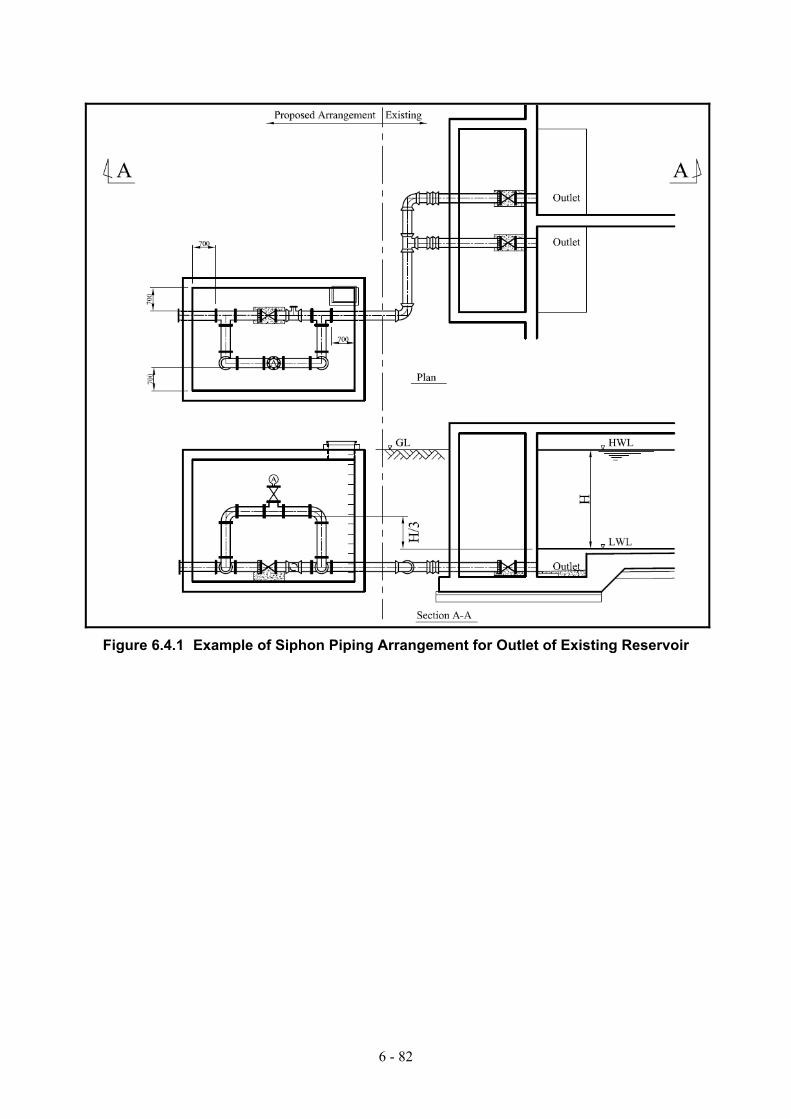
6 - 82
Figure 6.4.1 Example of Siphon Piping Arrangement for Outlet of Existing Reservoir

6 - 83
Figure 6.4.2 Example of Storehouse

6 - 84
(2) Supply from Existing Reservoir with the Installation of Emergency Shut-off Valve 1) General
As mentioned above, installation of emergency shut-off valve is one of typical solution to prevent massive flowing out in case of earthquake disaster but it is not feasible to install it in every reservoir due to its high cost. Therefore this valve should be applied only in case there is not enough space for construction of chamber for siphon arrangement.
There are several types of emergency shut-off valve. In this study, mechanical flow-sensor with manual return type, which does not require electricity, is considered (refer to Figure 6.4.3)
2) Required Preparation for Emergency Use and Particular Note for Emergency Use
Required preparation and particular note for emergency use are same as (1).
Figure 6.4.3 Example of Installation of Emergency Shut-off Valve to Existing Reservoir
(3) Supply from Gravity Transmission Main of Enqelab and Southern Ring Main 1) General
Concept of this method is similar to the use of existing reservoirs, in principle. At the place where existing reservoir is not available, but located near major transmission pipe namely Enqelab St. & Southern Ring Main, water for emergency use will be provided by these transmission mains (refer to Figure 6.4.4).

6 - 85
2) Required Preparation for Emergency Use
Following items should be prepared for emergency supply:
− Transmission pipe shall be branched by invert level tee, for example. − Fire hydrant shall be installed at the end of the branched pipe. − At least 3 temporary taps shall be prepared as mentioned in (1). − 1 storehouse as mentioned in (1) shall be prepared for 2 emergency supply bases and it
shall be prepared in nearest park
3) Particular Note for Emergency Use − Before emergency supply, all valves, which are connected to the transmission pipe for
downstream distribution, shall be closed, in order to keep water in the transmission pipe. Function of valves shall be checked at regular intervals.
− Temporary tap will be connected to the fire hydrant to supply water in case of the earthquake.
− Disinfection is regarded to be done at the reservoir which provides water to these transmission mains.
Figure 6.4.4 Schematic Illustration for Branch Connection from Transmission Main
(4) Supply from Deep Well 1) General
Wells will be used where reservoir is not available in and around the objective area.
In case of power failure after the earthquake, power supply for pumping-up to tank, for water reserve and disinfection, will be accommodated by a generator. However, preparation of generator for every well is not feasible in terms of project cost saving. To save cost, minimum necessary number of generators should be prepared. In addition, prepared generators should be stored in decentralized manner and they would be transported to the area where power failure is being

6 - 86
prolonged in case of disaster.
2) Special Consideration on Preparation for Generator
Based on the data provided by RTWO, average pump output power of wells in park is estimated as approximately 22 kW. On the other hand, average pump capacity of wells owned by TWWC is estimated as approximately 111 kW. Therefore, to save cost, well in park is firstly considered for emergency supply.
Preparing generator at each well is not feasible in terms of cost. Therefore the number of generators to be prepared is estimated so as to cover the number of wells in southern part of Tehran City, where it would be relatively difficult to be transported by tankers in terms of traffic condition after earthquake disaster.
All generators should be split into 3 to 4 groups to be kept at different places in the city in decentralized manner. In the case of disaster, the deployed generators shall be transported intensively to the part of the city where power failure is prolonged.
Vehicle for transportation of generator shall bring fuel with it. Fuel for diesel oil can be supplied at the service stations in and around the Study Area. Location of service stations, where diesel oil is available and its respective stock volume is presented in Figure 6.4.5.
3) Supplemental Installation of Emergency Water Tank
Sufficient numbers of emergency water tank shall be additionally installed in and around the coverage area by some deep wells, especially in southern part of the city where concentration of N-NO3 is high. Water kept in the emergency tank shall be exclusively used for drinking purpose especially for infants. Feature of emergency water tank is explained in (6).
4) Required Preparation for Emergency Use
Following items should be prepared for emergency supply. Generator shall be separately prepared and transported as mentioned above:
− Transmission pipe shall be branched by such as invert level tee. − Fire hydrant shall be installed at the end of the branched pipe. − At least 3 of temporary taps shall be prepared as mentioned in (1). − Switch board shall be installed so that power can be supplied from generator in case of
power failure. − Storehouse as mentioned in (1) shall be prepared.
In addition to the above, a well in a parks requires a tank with the capacity of approximately 50 m3. TWWC’s wells are regarded to have existing tank, but wells in parks are usually used for sprinkling and does not have tank to reserve water. Therefore tank shall be constructed for wells in parks.
5) Verification of Possibility for Emergency Use
Required dimension of tank is set as following basis:
− 30 % of total population (15,000 person/1 km-radius coverage area) is set as water supply interrupted population at the initial stage after the earthquake as mentioned in (1).
− Therefore 45 m3/d (3 L/d/person x 15,000 person) of water is required for drinking purpose, as mentioned in (1).
− Example of tank is shown in Figure 6.4.6.

6 - 87
Required number of emergency water tanks for supplemental installation is set as following basis:
− 30 % of total population (15,000 person/1 km-radius coverage area) is set as water supply interrupted population at the initial stage after the earthquake as mentioned in (1).
− Given 20 % of above is infant, total number of infant is 3,000 people − In order to supply drinking water for 7 days to 3,000 people, approximately 60 m3 of
water should be reserved in one coverage area. − Capacity of typical emergency tank is 20 m3. − Therefore, at least 3 emergency water tanks shall be installed at the required site.
Water quality of deep well is evaluated as following basis:
− According to the available water quality data of deep well given by TWWC, concentration of toxic heavy metal is under guideline value for drinking water in IRI.
− Therefore, water of deep well is generally fair enough for emergency supply purpose, as long as it is properly disinfected before supply.
− However, in some wells, concentration of N-NO3 is beyond the guideline value, especially in southern part of Tehran (refer to Figure 6.4.7).
− Therefore supplemental measures for securing of drinking water should be taken into account, especially for sensitive groups against N-NO3 such as infants.
6) Particular Note for Emergency Use − Temporary taps will be connected to the outlet of the tank in case of the earthquake. − Signboard should be prepared at the tank so that it shall remind people not to drink
without disinfection. − Appropriate amount of disinfectant (e.g., calcium hypochlorite) should be applied before
supply. − Laminated brief instruction manual for on-site disinfection should be prepared and kept at
the site. − Daily sprinkling work at wells in parks shall be done through new-installed tank, so that
water can be kept in tank. − Water quality of all wells designated as emergency supply bases should be monitored at
regular intervals.
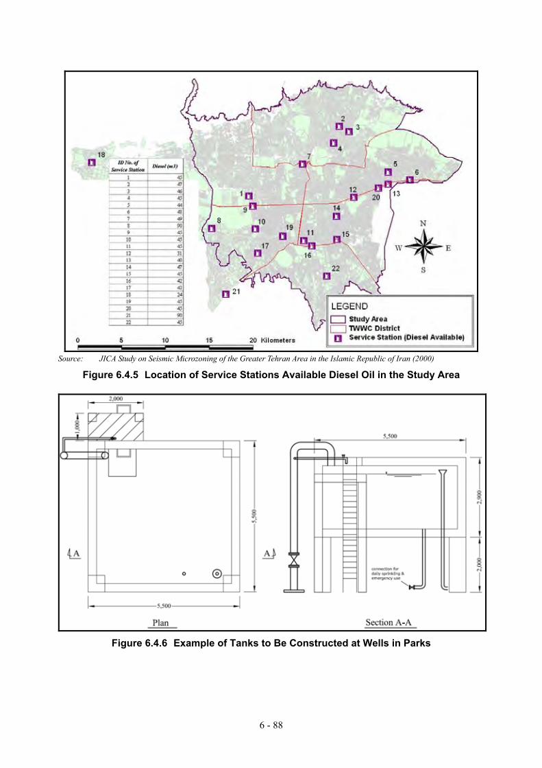
6 - 88
Source: JICA Study on Seismic Microzoning of the Greater Tehran Area in the Islamic Republic of Iran (2000)
Figure 6.4.5 Location of Service Stations Available Diesel Oil in the Study Area
Figure 6.4.6 Example of Tanks to Be Constructed at Wells in Parks

6 - 89
Source: TWWC
Figure 6.4.7 Concentration of N-NO3 for Deep Wells (5) Supply by Water Tanker
Water tanker will be used for non-coverage area by the above mentioned water supply bases. In this
Study, it is assumed that the existing water tanker will be used for emergency supply therefore cost for
water tanker is not considered in the project cost estimation.
(6) Supply by Emergency Water Tank
Water will be kept in the emergency water tank in case of the earthquake. This tank is connected to
distribution pipe. In normal situation, water enters into the tank from distribution pipe through inlet and
exits through outlet to go back to distribution pipe. In case inflow is suspended, due to the impact of
accident caused by earthquake disaster for example, in and outflow will be then suspended by the
function of air valve. As a result, water will be kept in emergency supply tank. Typical size of tank to
be prepared is set as 20m3/tank. Figure 6.4.8 gives general feature of the emergency tank.
In this Study, installed number of emergency tank is set as following basis:
• One tank at each evacuation place designated by TDMO • Three tanks at each well in southern part of Tehran, where concentration of N-NO3 is relatively high
as mentioned in (4).
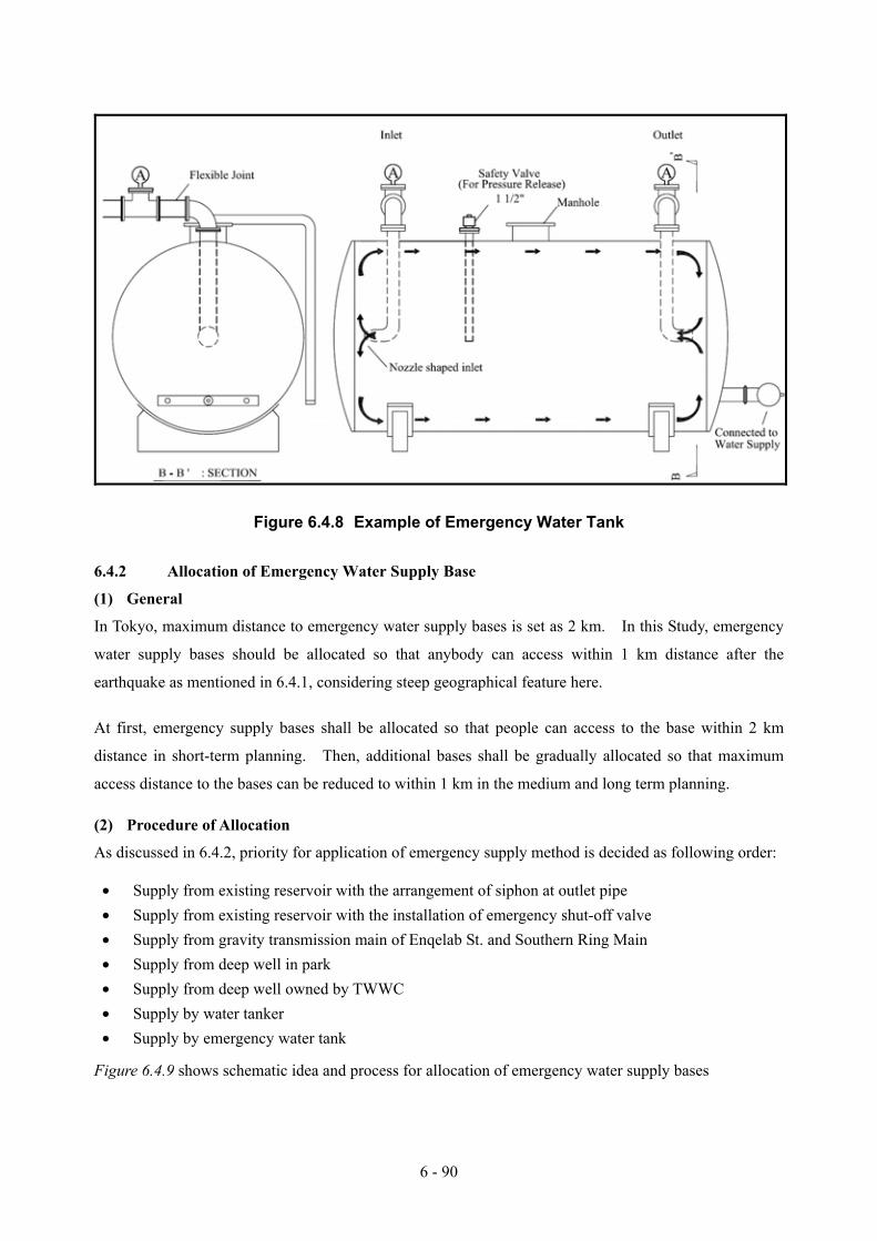
6 - 90
Figure 6.4.8 Example of Emergency Water Tank
6.4.2 Allocation of Emergency Water Supply Base
(1) General
In Tokyo, maximum distance to emergency water supply bases is set as 2 km. In this Study, emergency
water supply bases should be allocated so that anybody can access within 1 km distance after the
earthquake as mentioned in 6.4.1, considering steep geographical feature here.
At first, emergency supply bases shall be allocated so that people can access to the base within 2 km
distance in short-term planning. Then, additional bases shall be gradually allocated so that maximum
access distance to the bases can be reduced to within 1 km in the medium and long term planning.
(2) Procedure of Allocation
As discussed in 6.4.2, priority for application of emergency supply method is decided as following order:
• Supply from existing reservoir with the arrangement of siphon at outlet pipe • Supply from existing reservoir with the installation of emergency shut-off valve • Supply from gravity transmission main of Enqelab St. and Southern Ring Main • Supply from deep well in park • Supply from deep well owned by TWWC • Supply by water tanker • Supply by emergency water tank
Figure 6.4.9 shows schematic idea and process for allocation of emergency water supply bases
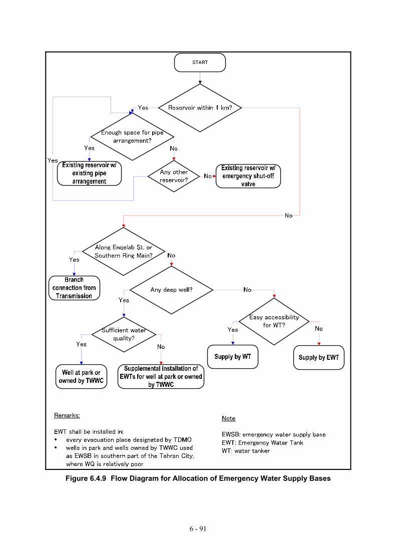
6 - 91
Figure 6.4.9 Flow Diagram for Allocation of Emergency Water Supply Bases

6 - 92
(3) Allocation of Emergency Water Supply Base
As mentioned in (1), emergency water supply bases will be allocated in a phased manner. Figure 6.4.10
shows allocation of supply bases after completion of short-term project. Figure 6.4.11 shows the final
shape of the planning for allocation of supply bases after the completion of medium and long-term
project.
Table 6.4.2 outlines the numbers of required emergency supply bases to be allocated.
Table 6.4.2 Required Number of Emergency Supply Bases by Type and Planning Phase Number
Type of supply points Short-term Mid &
long-term Total
1 Existing reservoir (Outlet arrangement ) 30 18 482 Existing reservoir (Emergency shut-off valve) 0 3 33 Gravity transmission (Southern Ring Main & Enqelab St.) 11 7 184 Deep well (owned by TWWC) 0 27 275 Deep well (in Park) 22 37 596 Emergency water tank 32 169 201
(4) Particular Notes in Allocation of Emergency Water Supply Base in Short-term Planning
As mentioned above, emergency water supply bases should be firstly prepared so that anybody can access
within 2 km distance after the earthquake in short term planning and subsequently additional bases should
be allocated so that the maximum access distance can be reduced to 1 km in medium and long-term
planning. However, in fact, nobody can predict precisely when or where a massive earthquake strikes.
In order to be prepared for unexpected disaster, it is necessary to give higher priority in allocation of
supply base to the area where the extent of damage is severer than the other areas, with the consideration
of damage under all possible earthquake scenarios.
Therefore, it is recommended that prioritization for the sequence of construction of the emergency water
supply bases should be considered in the short-term planning as well.
In the course of determination of priority, following items should be considered:
• The area where number of supply interrupted population would be greater (a). • The area where destruction of houses would be severer (b). • The area where power supply suspension would be prolonged (c). • The area where water tanker cannot access because the road does not have enough space (d).
Taking account for the above (a), for example, the sequence of construction for supply bases can be
proposed as following order (refer to Table 6.4.3). Here, 4 earthquake scenarios are considered in
prioritization of construction sequence of emergency supply bases:

6 - 93
• The area where supply interrupted population tops more than 10,000 under either of 3 scenarios (reservoir zone 2, 3, 4, 6 and 36)
• The area where supply interrupted population tops more than 10,000 under either of 2 scenarios (reservoir zone 1, 8, 10, 15-16-53, 18, 19, 20, 23, 26, 28, 31, 41, 62)
• Other areas
As for the other above items of (b), (c) and (d), it is recommended that prioritization should be examined
with reference to the previous relevant study report, such as the study report on electricity sector or JICA
Microzoning Study, for example.
Table 6.4.3 Supply Interrupted Population by Earthquake Scenario Zone No. Population N.tehran S.ray N.ray Mosha
1 90,017 90,017 0 2,488 90,017 22 275,753 275,753 18,417 36,755 275,753 43 177,147 17,160 16,857 25,440 0 34 159,628 16,339 15,352 21,940 2,792 35 128,276 6,804 8,444 7,644 2,706 06 261,615 14,362 11,545 17,511 0 37 337,737 1,832 0 0 0 08 136,112 136,112 0 0 136,112 210 50,910 50,910 0 0 50,910 211 120,856 2,842 0 0 0 012 24,225 24,225 0 0 0 113 285,713 285,713 0 168 0 114 42,081 42,081 0 0 0 1
15A 72,130 0 0 120 0 015-16-53 692,367 19,387 5,447 310,392 649 2
18 26,275 26,275 0 0 26,275 219 122,573 122,573 0 0 122,573 220 86,009 86,009 0 0 14,912 221 118,916 118,916 0 0 396 122 75,741 75,741 0 0 0 123 32,491 32,491 0 0 10,772 224 49,531 49,531 0 0 0 126 53,525 53,525 0 0 23,805 227 36,623 36,623 0 0 5,865 128 18,078 18,078 0 0 11,522 229 15,824 15,824 0 0 0 130 5,383 5,383 0 0 0 031 255,237 255,237 0 0 255,237 232 10,384 10,384 0 0 0 133 1,376 1,376 0 0 282 036 196,826 168,424 99,312 124,362 2,191 337 93,452 83,626 0 0 0 138 85,076 85,076 0 0 0 139 13,142 13,142 0 0 0 140 34,717 34,717 0 0 0 141 90,210 90,210 0 0 28,245 242 44,993 44,993 0 0 0 143 319,863 319,863 0 0 94 145 26,845 26,845 0 0 224 148 37,245 37,245 0 0 3,099 151 292,094 292,094 0 133 0 154 142,613 142,613 0 0 0 155 104,174 104,174 0 0 0 156 124,225 124,225 0 0 0 157 94,222 0 0 0 0 058 87,938 28,805 0 0 0 159 42,162 3,109 0 0 0 0
9-61 84,050 84,050 0 0 0 162 72,069 72,069 0 0 72,069 263 153,997 0 0 3,945 0 064 41,724 41,724 0 750 0 165 101,044 0 7,123 54,584 0 166 93,290 0 155 36,141 0 167 81,179 0 412 30,337 0 168 119,046 0 0 7,497 0 069 44,619 0 0 0 0 070 87,759 0 0 0 0 071 65,316 65,316 0 0 0 172 61,916 61,916 0 0 0 174 45,062 45,062 0 0 0 175 36,617 36,617 0 0 122 177 36,703 36,703 0 0 0 180 86,870 1,997 0 0 0 081 76,708 0 0 0 0 082 41,955 41,955 0 0 0 191 16,480 16,480 0 0 0 1
Note: Supply interrupted population (10,000 and over)Supply interrupted population (1 to 9,999)
Initial Supply Interruption Population by Scenario Number of Zones where SupplyInterrupted Population Exceeds 10,
000
Reservoir Zone

6 - 94
Figure 6.4.10 Allocation of Emergency Supply Bases after Completion of Short-term
Planning
Figure 6.4.11 Allocation of Emergency Supply Bases after Completion of Mid & Long-term
Planning

7 - 1
CHAPTER 7 DEVELOPMENT OF DRAFT EMERGENCY PLAN
7.1 Supply Interrupted Population and Restoration Period
A large scale earthquake cuts the lifelines of water service, electricity and gas. It cause destruction of
buildings and the roads, and bring a large influence to the citizens' lives. The victim will receive a large
pain. Therefore, TWWC is required to supply water at the earliest stage by using limited number of
manpower, material and equipment.
Damage on the water service can be minimized by making all the facilities earthquake-proof. However,
it requires long time and huge amount of money for the execution since lots of facilities should be
reinforced. It is important to take adequate anti-earthquake measures, which consider the balance of
facility reinforcement and the emergency measures.
It is, at first, required to understand the quantitative influence to the residents by earthquake, and then
evaluate the effects of several anti-earthquake measures. Accumulated water supply interrupted
population for the recovery period, which is calculated as “interrupted population” times “restoration
period”, is used as an index for the evaluation.
7.1.1 Definition of Damage Estimation as a Water Supply System
The water supply system of Tehran is composed of intake facilities, raw water transmission mains, clear
transmission mains, water treatment plants, distribution mains and service connections. A large number
of consumers will be affected when upstream of the system is damaged. The more upstream the damage
is, the more number of consumers are affected.
That is to say:
- When a power plant stops, it will influence the waterworks facilities (water treatment plants).
- When raw water transmission mains are damaged, water treatment plants at downstream will be
affected.
- When water treatment plants or transmission mains or pumping houses are damaged, water
distribution reservoirs at downstream will be affected.
- When pumps and pipes of wells are damaged, reservoir at downstream will be affected.
- When reservoirs and distribution trunk mains are damaged, reservoir zone at downstream will be
affected.
- When distribution sub mains and service connections are damaged, customers at downstream will be
affected.

7 - 2
River Dam Dam Dam
WTP WTP WTP WTP
powerstation
RES RES RES RES RES RES RES RES RES
damage
damage
damagedamage
damage
Figure 7.1.1 Image of Damage Effect to Other Facilities
It is not appropriate to judge the damage of water supply system from damage of each individual structure
and pipeline. As shown in Figure 7.1.1 it is necessary to understand the extent of the impact and the
scale of damage as a water supply system, in which water flows from raw water intake to the service
connection.
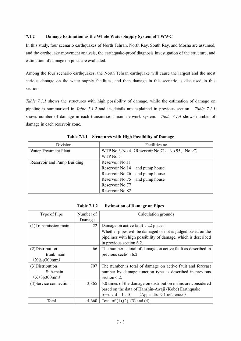
7 - 3
7.1.2 Damage Estimation as the Whole Water Supply System of TWWC
In this study, four scenario earthquakes of North Tehran, North Ray, South Ray, and Mosha are assumed,
and the earthquake movement analysis, the earthquake-proof diagnosis investigation of the structure, and
estimation of damage on pipes are evaluated.
Among the four scenario earthquakes, the North Tehran earthquake will cause the largest and the most
serious damage on the water supply facilities, and then damage in this scenario is discussed in this
section.
Table 7.1.1 shows the structures with high possibility of damage, while the estimation of damage on
pipeline is summarized in Table 7.1.2 and its details are explained in previous section. Table 7.1.3
shows number of damage in each transmission main network system. Table 7.1.4 shows number of
damage in each reservoir zone.
Table 7.1.1 Structures with High Possibility of Damage
Division Facilities no Water Treatment Plant WTP No.3-No.4(Reservoir No.71、No.95、No.97)
WTP No.5 Reservoir and Pump Building Reservoir No.11
Reservoir No.14 and pump house Reservoir No.26 and pump house Reservoir No.75 and pump house Reservoir No.77 Reservoir No.82
Table 7.1.2 Estimation of Damage on Pipes
Type of Pipe Number of Damage
Calculation grounds
(1)Transmission main 22 Damage on active fault:22 places Whether pipes will be damaged or not is judged based on the pipelines with high possibility of damage, which is described in previous section 6.2.
(2)Distribution trunk main (X≧φ300mm)
66 The number is total of damage on active fault as described in previous section 6.2.
(3)Distribution Sub-main
(X<φ300mm)
707 The number is total of damage on active fault and forecast number by damage function type as described in previous section 6.2.
(4)Service connection 3,865 5.0 times of the damage on distribution mains are considered based on the data of Hanshin-Awaji (Kobe) Earthquake b+c:d=1:5 (Appendix -9.1 references)
Total 4,660 Total of (1),(2), (3) and (4).

7 - 4
Table 7.1.3 Damage Point of Transmission Main Network System
transmission distribution distribution service total
main main sub main connection
WTP No.1 WTP-1_gravity 0 9 0 45 54
WTP-1_pump 8 10 95 525 638
WTP No.2 WTP-2_gravity1 1 2 0 10 13
WTP-2_gravity2 2 6 19 125 152
WTP-2_pump1 3 4 70 370 447
WTP-2_pump2 0 0 2 10 12
WTP No.3 WTP-3-4_gravity1 2 4 42 230 278
WTP No.4 WTP-3-4_gravity2 2 2 41 215 260
WTP No.5 WTP-5_gravity 4 17 380 1,985 2,386
Well WELL_east 0 1 6 35 42
WELL_west 0 11 52 315 378
total 22 66 707 3,865 4,660
damage pointwater treatment
plant
transmissionmainne twork
system
※ZONE42
※ZONE45
WTP-5
RES40RES21
RES41
RES25RES20
RES26
RES28
RES33
RES27
RES29
RES23 RES74
RES75
RES77
RES16RES53
RES51
RES36
RES63
RES52
WTP-1
RES 3 RES 4 RES 5 RES 6
RES34
WTP-2
RES59
RES80
RES81
RES85
WTP-2
RES 1RES 8
RES18
WTP-3WTP-4
RES71
RES94RES12
RES43
RES76
RES51
RES64
RES63
RES19
RES40
RES62
RES 7
RES70
RES69
RES68
RES15
RES65RES66
RES13
WTP-1
RES 3 RES 4 RES 5 RES 6
WTP-2
RES 7
RES 6 RES31
RES10
RES54RES 2
RES56
RES13
WTP-2
RES57
RES58
RES37
RES72
RES38
RES22
RES55RES39
RES 1
RES14
RES9-61BS14
RES18
RES22
RES24
RES32
RES30
RES91
RES38
RES82
RES83
WTP-1
WTP-3WTP-4
RES71
RES48
RES51
RES11
RES 2RES 7
RES62
BS17
RES21
※ZONE67
WTP-5gravity
WTP-3-4gravity1
WTP-3-4gravity2
WELLeast
WELLwest
WTP-1gravity
WTP-1pump
WTP-2gravity2
WTP-2gravity1
WTP-2pump2
WTP-2pump1
Place where possibility of damage is high on transmissiontrunk main (In the north tehran active fault)
total 22 points
Figure 7.1.2 Damage Place in Transmission Main

7 - 5
Table 7.1.4 Number of Damage in Each Reservoir Zone reservoir-zone
distributiontrunk main
distributionsub main
serviceconnection
total remarks column
1 1 0 5 62 6 11 85 1023 2 0 10 124 3 0 15 185 2 0 10 126 2 0 10 127 0 1 5 68 1 0 5 6
10 0 8 40 4811 0 1 5 612 0 0 0 013 0 0 0 014 0 5 25 30
15A 0 0 0 015-16-53 1 6 35 42
18 0 0 0 019 1 5 30 3620 1 99 500 60021 2 23 125 15022 0 41 205 24623 0 34 170 20424 6 9 75 9026 0 60 300 36027 2 42 220 26428 0 56 280 33629 1 6 35 4230 0 6 30 3631 0 0 0 032 1 8 45 5433 0 6 30 3636 11 52 315 37837 2 28 150 18038 2 4 30 3639 0 4 20 2440 1 16 85 10241 9 38 235 28242 0 2 10 1243 3 33 180 21645 1 14 75 9046 Unfinished region of pipe48 0 5 25 3051 0 2 10 1254 0 0 0 055 0 17 85 10256 0 0 0 057 0 0 0 058 0 6 30 3659 0 1 5 6
9-61 0 0 0 062 0 10 50 6063 0 0 0 064 0 0 0 065 0 0 0 066 0 0 0 067 0 0 0 068 0 0 0 069 0 0 0 070 0 0 0 071 0 1 5 672 2 19 105 12674 0 4 20 2475 1 4 25 3077 1 1 10 1278 reservoir zone of the future79 reservoir zone of the future80 0 1 5 681 0 0 0 082 0 9 45 5483 reservoir zone of the future84 reservoir zone of the future85 reservoir zone of the future91 1 9 50 60
total 66 707 3,865 4,638The damage of transmission trunkmain is added →total 4,660

7 - 6
7.1.3 Estimation of Supply Interrupted Population and Restoration Period
(1) Definition of Estimation of Supply Interrupted Population and the Restoration Period 1) Precondition of Restoration Simulation
The restoration simulation is done to examine the effects of several anti-earthquake measures by using the
indicator of total interrupted population for influence level. It is required to understand the quantitative
influence to the resident by the earthquake. Table 7.1.5 shows the precondition concerning the
restoration simulation.
Table 7.1.5 Precondition of Emergency Restoration Simulation
Before measures After measures
(a) Power plant Off the subject Off the subjectThe power plant stops for aboutone week because of the influencedue to the earthquake.
(b)Installation ofdisaster headquarters
For about one week immediatelyafter the earthquake(Period thatrequires it to establish the firstmoving system)
For about three days immediatelyafter the earthquake(Because thefirst moving system is maintained,the period is shortened.)
(c) Well It is possible to use it. It is possible to use it.
(d)Raw watertransmission main
Off the subject Off the subjectWater treatment plant in the down-stream stops for a certain period.
(e) Water treatment plant Off the subject Off the subjectThe targeted Water treatment plantstops for a certain period.
(f) Transmission main
In each water supply system,reserv-oir in the downstream of thedamage part is assumed to beinterrupted the water supply.
It is thought that an earthquake-proof pipe doesn't cause damage.
(g)Distribution trunkmain
Every the reservoir zone and distri-bution trunk main damage rate areassumed.
It is thought that an earthquake-proof pipe doesn't cause damage.
(h)Distribution sub mainSerivce connection
Every the reservoir zone and distri-bution sub main damage rate areassumed.
It is thought that an earthquake-proof pipe doesn't cause damage.
Content considered by restoration simulation Content that can be consideredoutside of restoration simulation
Item
When facilities have uncertainties in the functions and restoration period, they are excluded from
restoration simulation.
When damages on power plant and/or raw water transmission main and/or water treatment plant are
considered, water supply interrupted population (for instance, γdays × population of water supply
interruption in case of the power plant) can be calculated by adding the restoration period of each facility
to the result of this restoration simulation. (b) and (c) of Table 7.1.3 and (f), (g) and (h) are considered.
Figure 7.1.3 shows an example of the calculation.
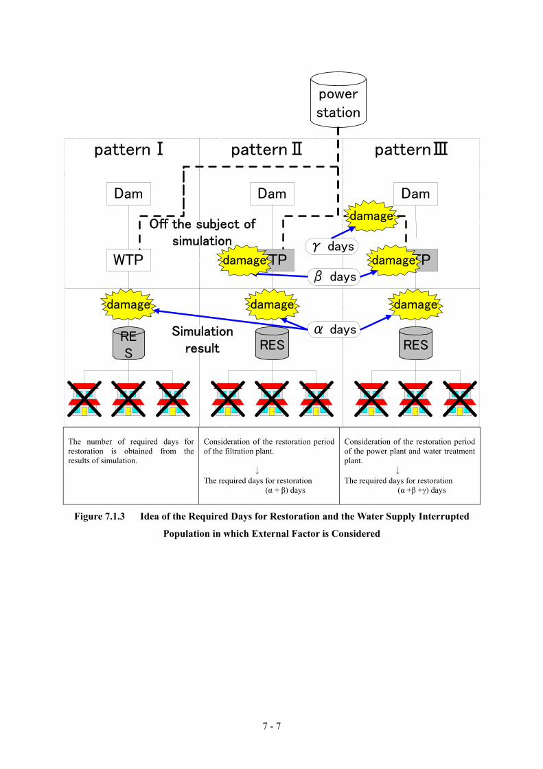
7 - 7
patternⅢpatternⅡpatternⅠ
WTP
powerstation
RES
Dam
WTP
RES
Dam
WTP
RES
damage
Dam
damage damage
damage
damage
α days
γ days
β days
Simulationresult
Off the subject ofsimulation
damage
The number of required days for restoration is obtained from the results of simulation.
Consideration of the restoration period of the filtration plant. ↓ The required days for restoration
(α + β) days
Consideration of the restoration period of the power plant and water treatment plant. ↓ The required days for restoration
(α +β +γ) days
Figure 7.1.3 Idea of the Required Days for Restoration and the Water Supply Interrupted
Population in which External Factor is Considered

7 - 8
2) Calculation procedure of restoration simulation
Figure 7.1.4 shows the calculation procedure of the restoration simulation. The method of using this
simulation is described below.
- To calculate water supply interrupted population and the required days for restoration “before taking
countermeasures”
- To calculate the water supply interrupted population and the required days for restoration “after taking
countermeasures” by comparing the target of facility reinforcement and required days for restoration.
- To evaluate accumulated water supply interrupted population for the period (= the water supply
interrupted population ×required days for restoration) “before” and “after” taking countermeasures and to
evaluate the measures.
Hereinafter this paper explains a) Setting of population of each reservoir zone, b) Setting of transmission
main network system, c) Setting of organization for restoration of pipeline, d) Calculation of restoration
process, and e) Calculation of the water supply interrupted population.

7 - 9
S
Earthquake motion analysis
Damage estimation fortransmisstion and distribution
pipelines (t=0)
Earthquake-resistant diagnosisfor facility tructures and
equipment(t=0)
Setting of target
e-1) Calculation of initial of thewater supply interrupted
population(t=0)
d) Calculation of restorationprocess(t=1~n)
e-2) Calculation of the watersupply interrupted population
(t=1~n)
b) Setting of transmissionmain network system
f) Output result(t=0~n)
g) Evaluation(Total suspension of thewater supply population ect)
Plan of making toearthquake-proof of
facilities
a) Setting of population ofeach reservoir zone
Case-1(t=0~n)Case-2
(t=0~n)Case-N(t=0~n)
E
(Output result)・restoration period・the water supply interrupted population(t=0~n)・rate of water supply(t=0~n)・Mending day(pipe,reservoir zone)・Number of turning on teams(t=0~n)
After measure
c) Setting of organizationfor restoration of pineline
Calculation of initialpopulation of the water
supply interruption
Emergency response
Simulate restoration
Output andanalysis
Figure 7.1.4 Calculation Procedure of Restoration Simulation

7 - 10
a) Setting of population of each reservoir zone
The population of 6,938,734 persons in Tehran City in 2005 (Information of Iran Statistics data, District
21-22 were excluded) is allocated to each reservoir zone for the analysis as shown in Table 7.1.6.
Table 7.1.6 Population of Each Reservoir remarks column
1 90,017 90,0172 275,753 275,7533 177,147 177,1474 159,628 159,6285 128,276 128,2766 261,615 261,6157 337,737 337,7378 136,112 136,112
10 50,910 50,91011 120,856 120,85612 24,225 24,22513 285,713 285,71314 42,081 42,081
15A 72,130 72,13015-16-53 692,367 692,367
18 26,275 26,27519 122,573 122,57320 86,009 86,00921 118,916 118,91622 75,741 75,74123 32,491 32,49124 49,531 49,53126 53,525 53,52527 36,623 36,62328 18,078 18,07829 15,824 15,82430 5,383 5,38331 255,237 255,23732 10,384 10,38433 1,376 1,37636 196,826 196,82637 93,452 93,45238 85,076 85,07639 13,142 13,14240 34,717 34,71741 90,210 90,21042 44,993 44,99343 319,863 319,86345 26,845 26,84546 23,174 a part before measures to Res7448 37,245 37,24551 292,094 292,09454 142,613 142,61355 104,174 104,17456 124,225 124,22557 94,222 94,22258 87,938 87,93859 42,162 42,162
9-61 84,050 84,05062 72,069 72,06963 153,997 153,99764 41,724 41,72465 101,044 101,04466 93,290 93,29067 81,179 81,17968 119,046 119,04669 44,619 44,61970 87,759 87,75971 65,316 65,31672 61,916 61,91674 45,062 21,88875 36,617 36,61777 36,703 18,30678 16,468 a part before measures to Res7779 1,929 a part before measures to Res7780 86,870 86,87081 76,708 42,76282 41,955 27,32183 14,634 a part before measures to Res8284 18,796 a part before measures to Res8185 15,150 a part before measures to Res8191 16,480 16,480
計 6,938,734 6,938,734
number of person of person2005
after measuresbefore measuresreservoir no
Source : Iran Statistics data 2005(District21-22 is excluded)

7 - 11
b) Setting of transmission main network system Figure 7.1.5 shows transmission main network system. It is classified by transmission main network
system from each of the water treatment plant, during daily maximum water supply (as of July 19th
2005).
※ZONE42
※ZONE45
WTP-5
RES40RES21
RES41
RES25RES20
RES26
RES28
RES33
RES27
RES29
RES23 RES74
RES75
RES77
RES16RES53
RES51
RES36
RES63
RES52
WTP-1
RES 3 RES 4 RES 5 RES 6
RES34
WTP-2
RES59
RES80
RES81
RES85
WTP-2
RES 1RES 8
RES18
WTP-3WTP-4
RES71
RES94RES12
RES43
RES76
RES51
RES64
RES63
RES19
RES40
RES62
RES 7
RES70
RES69
RES68
RES15
RES65RES66
RES13
WTP-1
RES 3 RES 4 RES 5 RES 6
WTP-2
RES 7
RES 6 RES31
RES10
RES54RES 2
RES56
RES13
WTP-2
RES57
RES58
RES37
RES72
RES38
RES22
RES55RES39
RES 1
RES14
RES9-61BS14
RES18
RES22
RES24
RES32
RES30
RES91
RES38
RES82
RES83
WTP-1
WTP-3WTP-4
RES71
RES48
RES51
RES11
RES 2RES 7
RES62
BS17
RES21
※ZONE67
WTP-5gravity
WTP-3-4gravity1
WTP-3-4gravity2
WELLeast
WELLwest
WTP-1gravity
WTP-1pump
WTP-2gravity2
WTP-2gravity1
WTP-2pump2
WTP-2pump1
Figure 7.1.5 Transmission Main Network System

7 - 12
c) Setting of system of recovery efforts
The organization for pipe repair works is set as Table 7.1.7 based on the hearing results from TWWC.
The hearing revealed that transmission mains are repaired by TWWC head office and Water District
offices are responsible for distribution trunk mains, distribution sub mains, and service connections.
Table 7.1.7 Organization for Pipe Repair Works
Type of pipe Manager Number Grounds Transmission main
TWWC head office
3 teams System of recovery of transmission main One team is composed of 12 persons
Distribution trunk-main
Water Districts
18 teams It sets it in consideration of the number of heavy equipment. 6districts×3 post One team is composed of 12 persons
Distribution Sub-main
Water Districts
54 teams 6 districts×3 post×3team One team is composed of 12 persons
Service connection
Water Districts
108 groups 6 districts×3 post×3team×2group One team is composed of 3-4 persons
Emergency Post
Leak Detection(4 persons)
RepairOnly Replace,New Install
(4 persons)
team 3
team 2
team 1 (14 persons)
Teamleader 1 person
TELoperator 2persons
Group1 4persons
Group2 4persons
Backhoa opertor 1 person
Asphaft cutter 1 person
Security 1 person
Daily 7:30-16:00Three shifts in 24 hours
1group :3repair men 1driver
10-14 people in otheremergency posts
Figure 7.1.6 Organization of Emergency Post(Information of district 5)

7 - 13
d) Calculation of restoration process
The restoration simulation calculates the daily change of numbers of damage immediately after the
earthquake (t=0) up to restoration completion day (t=N). The basic idea of the restoration simulation is
described below.
Basic idea to simulate restoration
- One week is assumed for the period for calling staffs, collecting damage information, and establishment of restoration organization “before taking countermeasures”. It is set as three days “after taking countermeasures”, such as preparation of manual and improvement of staff’s wills.
- Pipe restoration teams are distributed to each transmission main network system at the rates of damage number as shown in Table 7.1.3.
- The pipes are considered to be repaired from upstream to downstream (i.e., transmission main→distribution trunk main→distribution sub main→service connection). It is assumed that two teams
cannot work at one time on the same pipeline since restoration work of transmission line and distribution mains should be done from upstream to downstream.
- The restoration period of pipe repair at one place is set as twice of the usual restoration period, which information is obtained by hearing of TWWC, in consideration of difficulties in a traffic condition after earthquake due to building collapse, interruption of the road and others.
The results the simulation are shown in Table 7.1.8.
Table 7.1.8 Required Period for Pipe Restoration
Type of pipe Diameter of pipe Required period for restoration
Transmission main
X≧φ600mm
φ600mm>X≧φ300mm
0.33 Part/day/team
0.5 Part/day/team
Distribution trunk main
X≧φ300mm
0.5 Part/day/team
Distribution Sub main
X<φ300mm
1.0 Part/day/team
Service connection 2.0 Part/day/team

7 - 14
e) Calculation of the water supply interrupted population
Water supply interrupted population is calculated from “the population of each reservoir zone” and
“damage rate of pipe” of transmission main, distribution trunk main, distribution sub-main, and service
connection. A basic idea for the calculation of the water supply interrupted population is described
below.
Basic Idea for Calculation of Water Supply Interrupted Population
- Water supply interrupted population is calculated based on the damage rate of pipe of transmission mains, distribution trunk mains, distribution sub-mains, and service connections.
- The damage of power plants, raw water transmission mains, water treatment plants, reservoirs, and pump houses are excluded from the restoration simulation.
- When transmission main is damaged, water supply in all downstream reservoir zones is assumed to be interrupted.
- When transmission main is not damaged, the damage rate of reservoir zone is calculated by using the damage rate of distribution trunk mains and the damage rate of distribution sub-mains.
The water supply rate of interrupted reservoir zone
= 1 -(1-damage rate of distribution trunk mains)×(1-damage rate of distribution sub mains)
The water supply interrupted population in reservoir zone
= population of reservoir zone × the water supply rate of interrupted reservoir zone

7 - 15
(2)The analysis results
The outline of Case Study and the output of the study, such as water supply interrupted population,
required days for restoration days and recovery efforts team, in each case are explained below.
1) Case study
In order to achieve the target restoration period of one month, suitable countermeasures, which consider
balance of reinforcement and emergency measures, are examined by restoration simulation. Conditions
of the simulation of each case for the case study are summarized in Table 7.1.9.
Table 7.1.9 Conditions of Simulation for Each Case CASE-1 Without Any Countermeasures
CASE-2 When transmission mains are earthquake-proof
CASE-3 When transmission mains are earthquake-proof and the number of restoration team
is increased. CASE-4 When transmission mains are earthquake-proof and active fault measures are
adopted in distribution trunk mains CASE-5 When transmission mains are earthquake-proof and active fault measures are
adopted in distribution trunk mains and distribution sub mains.
The number of damage for each case is summarized in Table 7.1.10. The number of damaged locations
in transmission mains is 0 in CASE-2-CASE-5 after taking countermeasures, while it is 22 in CASE-1
before taking countermeasures. The number of damage locations in distribution trunk mains is 3 in
CASE-4 when the active fault measures of distribution trunk mains are adopted, and CASE-5 when the
active fault measures of distribution trunk mains and distribution sub mains are adopted. Moreover, the
damage number of water distribution sub-mains in CASE-5, which considers countermeasures of
distribution sub mains on active fault, is 533.
Table 7.1.10 Damage Number of Each Case
Notransmission
maindistributiontrunk main
distribution sub main
surviceconnection
total
(number) (number) (number) (number) (number)
CASE-1 22 66 707 3,865 4,660
CASE-2 0 66 707 3,865 4,638
CASE-3 0 66 707 3,865 4,638
CASE-4 0 3 707 3,865 4,575
CASE-5 0 3 533 3,865 4,401

7 - 16
2) The water supply interrupted population and required period for restoration
The water supply interrupted population and required period (days) for restoration in each case study are
shown in Table 7.1.11. In CASE-1, initial water supply interrupted population is 3,995 thousand (rate
57.6%) and accumulated interrupted population throughout the period is 125,770 thousand while the
restoration period is 82 days.
In CASE-2, initial interrupted population is 1,739 thousand (25.0%) and accumulated interrupted
population throughout the period is 64,483 thousand while the restoration period is 73 days.
In CASE-3, initial interrupted population is 1,739 thousand (25.0%) and accumulated interrupted
population throughout the period is 29,728 thousand while the restoration period is 30 days.
In CASE-4, initial interrupted population is 1,640 thousand (23.6%) and accumulated interrupted
population throughout the period is 48,382 thousand while the restoration period is 65 days.
In CASE-5, initial interrupted population is 1,591 thousand (22.9%) and accumulated interrupted
population throughout the period is 45,015 thousand while the restoration period is 60 days.
Table 7.1.11 The Water Supply Interrupted Population and Required Days for Restoration
No Initial Initial rate total
(1000 person) (%) (1000 person) (day)
CASE-1 3,995 57.6 125,770 82
CASE-2 1,739 25.0 64,483 73
CASE-3 1,739 25.0 29,728 30
CASE-4 1,640 23.6 48,382 65
CASE-5 1,591 22.9 45,015 60
the water supply interrupted population required daysfor restoration
※Initial rate=initial water supply interrupted population ÷6,938,734 people(Information of Iran Statistics data)×100
Figure 7.1.7 shows the transition of the water supply interrupted population and restoration rate in each
case. In CASE-1, restoration work of transmission main will be completed on the 7th day, and repair of
distribution trunk main will be completed on the 38th day. On the other hand, distribution trunk main is
restored on the 22nd day in CASE-2 (about 1/2 of CASE-1), and restored on the 13th day in
CASE-3-CASE-5 (about 1/3 of CASE-1).

7 - 17
CASE-1(Tehran City)
0
1,000
2,000
3,000
4,000
5,000
1st 8st 15st 22st 29st 36st 43st 50st 57st 64st 71st 78st
the w
ater
supply
inte
rrupt
ed
popula
tion
0
20
40
60
80
100
rest
ora
tion
rate
%
the water supply interrupted populationrestoration rate
(1000 people)
transmission trunk main
distr ibution trunk main
CASE-2(Tehran City)
0
1,000
2,000
3,000
4,000
5,000
1st 8st 15st 22st 29st 36st 43st 50st 57st 64st 71st 78st
the w
ater
supp
lyin
terr
upt
edpo
pul
atio
n
0
20
40
60
80
100
rest
ora
tion r
ate
%
the water supply interrupted populationrestoration rate
(1000 people)
distribut ion trunk main
CASE-3(Tehran City)
0
1,000
2,000
3,000
4,000
5,000
1st 8st 15st 22st 29st 36st 43st 50st 57st 64st 71st 78st
the w
ater
suppl
yin
terr
upt
edpo
pula
tion
0
20
40
60
80
100
rest
ora
tion r
ate
%
the water supply interrupted populationrestoration rate
(1000 people)
distr ibution trunk main
CASE-4(Tehran City)
0
1,000
2,000
3,000
4,000
5,000
1st 8st 15st 22st 29st 36st 43st 50st 57st 64st 71st 78st
the w
ater
supp
lyin
terr
upt
ed
popula
tion
0
20
40
60
80
100
rest
ora
tion
rate
%
the water supply interrupted populationrestoration rate
(1000 people)
distr ibution trunk main
CASE-5(Tehran City)
0
1,000
2,000
3,000
4,000
5,000
1st 8st 15st 22st 29st 36st 43st 50st 57st 64st 71st 78st
the w
ater
supply
inte
rrupt
edpo
pul
atio
n
0
20
40
60
80
100
rest
ora
tion r
ate
%
the water supply interrupted populationrestoration rate
(1000 people)
distr ibution trunk main
Figure 7.1.7 Transition of the Water Supply Interrupted Population of Case Study

7 - 18
The transition of the water supply interrupted population in each reservoir zone is shown in Figure 7.1.8-
Figure 7.1.9 (CASE-1 and CASE-3). Moreover, the transition of the water supply interrupted
population in each transmission main network system is shown in APPENDIX- 9.2. The water supply
interrupted population in each reservoir zone system is shown in APPENDIX- 9.3. To understand the
assumed damage region in APPENDIX-9.3, the water supply interrupted population of four scenario
earthquakes is shown.
Figure 7.1.8 Water Supply Interrupted Population(t=0 and t=7)

7 - 19
Figure 7.1.9 Water Supply Interrupted Population(t=14 and t=21 and t=30)

7 - 20
3) Pipe Restoration Team
The number of pipe restoration teams in each case is shown in Table 7.1.12. In CASE-1, 3,059 teams in
total are required among them 82 teams are for transmission mains, 315 teams are for distribution trunk
mains, and 2,662 teams are for distribution sub-mains (service connection is included).
Total number of pipe restoration teams decreases in CASE-2, CASE-4, and CASE-5 because the number
of damage location is also decreased. In CASE-3, the number of standby team, in other words late start
team, has increased because restoration of distribution trunk main should be done from upstream to
downstream and simultaneous works cannot be done. The teams are composed of TWWC pipe
restoration team and assistant teams from water companies in other provinces and private companies.
Table 7.1.12 The Water Supply Interrupted Population and Required Days for Restoration
Notransmission
maindistribution trunk
mainother
totalmanpower
(team) (team) (team) (team)
CASE-1 82 315 2,662 3,059
CASE-2 0 175 2,622 2,797
CASE-3 0 232 2,814 3,046
CASE-4 0 9 2,709 2,718
CASE-5 0 9 2,589 2,598
The transition of number of pipe restoration team in each case is shown in Figure 7.1.10.
In CASE-1, 21 teams will become standby for one week immediately after the earthquake, i.e. 3 for
transmission mains and 18 for distribution trunk mains And then, with the recovery of transmission
mains and distribution trunk mains, the number of restoration teams for distribution sub-mains will be
increased.
The transition of restoration team depends on its countermeasures in CASE-2-CASE-5. In CASE-2, lots
of restoration team can work at one time in wide area since all of the repair works are at downstream of
distribution trunk main. As a result, the restoration period in CASE-2 will become shorter than CASE-1.
In CASE-4 and CASE-5, restoration period will be shorter than CASE-2, since repair works can be
started from distribution sub-mains.
In CASE-3, restoration period becomes shorter than CASE-2 because of double input of restoration teams,
which are consisted of TWWC teams and teams of assistants.

7 - 21
0
20
40
60
80
100
120
140
1st 8st 15st 22st 29st 36st 43st 50st 57st 64st 71st 78st
Num
ber
of
recove
ry e
ffort
s te
ams
CASE-1
CASE-2
CASE-3
CASE-4
CASE-5
Figure 7.1.10 Numerical Transition of Emergency Restoration Groups
The allocation of emergency restoration teams, used for the simulation, is shown in Table 7.1.13. Nine
teams are assumed to work from the initial stage in WTP-5 route, which has large damage. The
restoration teams, which can finish the repair in short period, are assumed to assist other reservoir zone.
These teams are team 1 of District Ⅳ, team1 of team1-team3 and District Ⅵ of team2 and District Ⅴ,
and team 4.
Table 7.1.13 Arrangement of Emergency Restoration Team
District Ⅰ team 1 WTP-5_gravity (Completion)
team 2 WTP-5_gravity (Completion)
team 3 WTP-5_gravity (Completion)
District Ⅱ team 1 WTP-5_gravity (Completion)
team 2 WTP-5_gravity (Completion)
team 3 WTP-5_gravity (Completion)
District Ⅲ team 1 WTP-1_pump (Completion)
team 2 WTP-1_pump (Completion)
District Ⅳ team 1 WTP-3_gravity2 → WTP-3_gravity1 (Completion)
team 2 WTP-3_gravity2 → WTP-3_gravity1 (Completion)
team 3 WTP-5_gravity (Completion)
District Ⅴ team 1 WTP-2_pump2 → WTP-2_pump1 (Completion)
team 2 WTP-2_pump2 → WTP-2_pump1 (Completion)
team 3 WTP-2_pump2 → WTP-2_gravity1 → WTP-2_gravity2 (Completion)
District Ⅵ team 1 WELL_west → WELL_east (Completion)
team 2 WTP-5_gravity (Completion)
team 3 WTP-5_gravity (Completion)
team 4 WTP-1_gravity → WELL_east (Completion)
team no Arrangement of recovery efforts team

7 - 22
The restoration works are assumed to be done from transmission main, distribution trunk main, and then
distribution sub-main (service connection is included). Restoration of transmission main is from
reservoir zone in the upstream to the zone downstream. As an example, the restoration process in
transmission main network system in WTP-5 gravity route is shown in Figure 7.1.11 and Table 7.1.14.
WTP-5
RES40RES21
RES41
RES20
RES26
RES28
RES33
RES27
RES29
RES23 RES74
RES75
RES77
※Zone 45 is restored simultaneouslywith reservoir No.40.
※Zone 78-79 is restoredsimultaneously with reservoir No77.
※Zone 46 is restored simultaneouslywith reservoir No74.
Figure 7.1.11 Transmission Trunk Main Network of WTP-5 Gravity Route
Table 7.1.14 Emergency Restoration Process in CASE-1 and CASE-3
the order ofreservoir zone
transmissiontrunk main
transmissiontrunk main
(day) (day)
41 0 8 ~ 9 10 ~ 11 0 4 ~ 4 6 ~ 8
13 ~ 16
20 11 12 ~ 12 16 ~ 16 0 4 ~ 4 8 ~ 14
18 ~ 18
21 ~ 31
26 14 0 ~ 0 31 ~ 39 0 0 ~ 0 14 ~ 17
28 16 0 ~ 0 39 ~ 46 0 0 ~ 0 17 ~ 21
33 16 0 ~ 0 46 ~ 47 0 0 ~ 0 21 ~ 21
23 16 0 ~ 0 47 ~ 51 0 0 ~ 0 21 ~ 23
27 16 17 ~ 17 52 ~ 57 0 5 ~ 5 23 ~ 26
29 18 19 ~ 19 57 ~ 58 0 5 ~ 5 26 ~ 26
74 18 0 ~ 0 58 ~ 58 0 0 ~ 0 26 ~ 26
46 18 0 ~ 0 0 ~ 0 0 0 ~ 0 0 ~ 0
75 18 19 ~ 19 58 ~ 59 0 5 ~ 5 26 ~ 26
77 18 19 ~ 19 59 ~ 59 0 5 ~ 5 26 ~ 26
78 18 0 ~ 0 0 ~ 0 0 0 ~ 0 0 ~ 0
79 18 0 ~ 0 0 ~ 0 0 0 ~ 0 0 ~ 0
40 18 19 ~ 19 59 ~ 61 0 5 ~ 5 27 ~ 28
45 18 19 ~ 20 62 ~ 63 0 5 ~ 5 28 ~ 28
21 18 20 ~ 20 63 ~ 67 0 5 ~ 5 28 ~ 30
(day) (day) (day) (day)
emergency restoration(CASE-1) emergency restoration(CASE-3)
distributiontrunk main
distributionsub main
distributiontrunk main
distributionsub main

7 - 23
In CASE-1, restoration period of transmission main is 18 days, distribution trunk main is restored on the
20th day, and distribution sub main (service connection is included) is restored on the 67th day.
In CASE-3, distribution trunk main is restored on the 5th day, and distribution sub main (service
connection is included) is restored on the 30th day and satisfy the target.
The emergency restoration processes in other transmission main systems are shown in Appendix -9.4.
0 10 20 30 40 50 60 70 80 90
4120262833232729747577404521
rese
rvio
r no
days
transmission trunk main
distribution trunk main
distribution and servicepipe
《WTP5_gravity》
the order ofreservoir zone
Figure 7.1.12 Emergency Restoration Process in CASE-1
0 10 20 30 40 50 60 70 80 90
4120262833232729747577404521
rese
rvio
r no
days
distribution trunk main
distribution and servicepipe
《WTP5_gravity》
The order ofreservoir zone
Figure 7.1.13 Emergency Restoration Process in CASE-3

7 - 24
(3) Analysis on Effect of Anti-Earthquake Measures
Anti-earthquake measures can be classified into two, i.e. reinforcement of facilities to be
earthquake-proof and the emergency measures. The method of “reinforcement of facilities to be
earthquake-proof” is effective to reduce water supply interrupted population, while “the emergency
measures” are effective to shorten the emergency restoration period.
Damage on water supply system can be minimized by making all the facilities earthquake-proof.
However, the work volume is huge and long period and huge amount of money will be required for its
execution. And then it is required to find adequate countermeasures, which consider the balance of
facility reinforcement and emergency measures in consideration of budget.
The first step is to understand the quantitative influence of the water supply interrupted population and
restoration period to the residents. The next step is to examine the effects of anti-earthquake measures
of CASE-2-CASE-5 by using the above influence level found in the first step.
Figure 7.1.14 shows the water supply interrupted population and the restoration period in each case.
The difference of the initial water supply interruption population in CASE-1 and CASE-2-CASE-5 is
mainly due to effects of restoration of transmission mains. The difference of restoration period in
CASE-2 and CASE-3 is due to an effect of the increase of emergency restoration team. In CASE-3, the
target for the restoration period of one month can be achieved.
CASE STUDY
0
1,000
2,000
3,000
4,000
5,000
0 10 20 30 40 50 60 70 80 90 100
restoration period(days)
initia
l pop
ulat
ion o
f w
ater
supp
ly inte
rrupt
ion
(1000 p
eop
le)
CASE-1
CASE-2CASE-3
CASE-4
CASE-5
Settingof target
reducti
on o
f scale
shortening at period
Figure 7.1.14 Water Supply Interrupted Population and Restoration Period in each Case
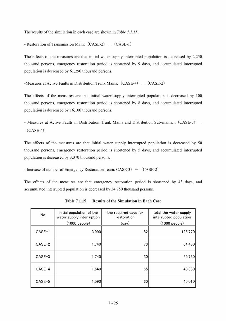
7 - 25
The results of the simulation in each case are shown in Table 7.1.15.
- Restoration of Transmission Main:(CASE-2)-(CASE-1)
The effects of the measures are that initial water supply interrupted population is decreased by 2,250
thousand persons, emergency restoration period is shortened by 9 days, and accumulated interrupted
population is decreased by 61,290 thousand persons.
-Measures at Active Faults in Distribution Trunk Mains:(CASE-4)-(CASE-2)
The effects of the measures are that initial water supply interrupted population is decreased by 100
thousand persons, emergency restoration period is shortened by 8 days, and accumulated interrupted
population is decreased by 16,100 thousand persons.
- Measures at Active Faults in Distribution Trunk Mains and Distribution Sub-mains.:(CASE-5)-
(CASE-4)
The effects of the measures are that initial water supply interrupted population is decreased by 50
thousand persons, emergency restoration period is shortened by 5 days, and accumulated interrupted
population is decreased by 3,370 thousand persons.
- Increase of number of Emergency Restoration Team: CASE-3)-(CASE-2)
The effects of the measures are that emergency restoration period is shortened by 43 days, and
accumulated interrupted population is decreased by 34,750 thousand persons.
Table 7.1.15 Results of the Simulation in Each Case
Noinitial population of the
water supply interruptionthe required days for
restorationtotal the water supplyinterrupted population
(1000 people) (day) (1000 people)
CASE-1 3,990 82 125,770
CASE-2 1,740 73 64,480
CASE-3 1,740 30 29,730
CASE-4 1,640 65 48,380
CASE-5 1,590 60 45,010

7 - 26
When CASE-2, CASE-4, and CASE-5 are seen, it is difficult to achieve the target of making to
earthquake-proof only because of making earthquake-proof.
Therefore, it is necessary to consider the balance of the reduction of the damage scale and for shortening
the restoration period like CASE-3.
The target of making earthquake-proof can be achieved by executing making of transmission main and
distribution trunk main earthquake-proof (6.2 references), and doubling the recovery efforts team.
When transmission main and distribution trunk main earthquake-proof measures are executed, it is
required to examine the priority and the balance of “the amount of facility reinforcement works” and “the
number of recovery teams” in consideration of budget.
The simulation is the results of analysis assuming the damage in transmission main, distribution trunk
main, distribution sub-main and service connection only. When damages on power plant and raw water
transmission main, and water treatment plant are considered, each restoration period and the water supply
interrupted population must be added to the result of the simulation.
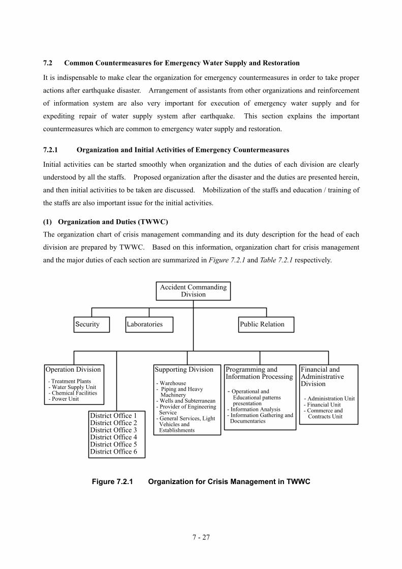
7 - 27
7.2 Common Countermeasures for Emergency Water Supply and Restoration
It is indispensable to make clear the organization for emergency countermeasures in order to take proper
actions after earthquake disaster. Arrangement of assistants from other organizations and reinforcement
of information system are also very important for execution of emergency water supply and for
expediting repair of water supply system after earthquake. This section explains the important
countermeasures which are common to emergency water supply and restoration.
7.2.1 Organization and Initial Activities of Emergency Countermeasures
Initial activities can be started smoothly when organization and the duties of each division are clearly
understood by all the staffs. Proposed organization after the disaster and the duties are presented herein,
and then initial activities to be taken are discussed. Mobilization of the staffs and education / training of
the staffs are also important issue for the initial activities.
(1) Organization and Duties (TWWC)
The organization chart of crisis management commanding and its duty description for the head of each
division are prepared by TWWC. Based on this information, organization chart for crisis management
and the major duties of each section are summarized in Figure 7.2.1 and Table 7.2.1 respectively.
Accident Commanding
Division
Security Laboratories Public Relation
Operation Division - Treatment Plants - Water Supply Unit - Chemical Facilities - Power Unit
District Office 1District Office 2District Office 3District Office 4District Office 5District Office 6
Supporting Division
- Warehouse - Piping and Heavy Machinery - Wells and Subterranean - Provider of Engineering Service - General Services, Light Vehicles and Establishments
Programming andInformation Processing
- Operational and Educational patterns presentation - Information Analysis - Information Gathering and Documentaries
Financial andAdministrativeDivision
- Administration Unit - Financial Unit - Commerce and Contracts Unit
Figure 7.2.1 Organization for Crisis Management in TWWC

7 - 28
Table 7.2.1 Duty Description of Each Section in Emergency Unit in the Organization Duty Description
Accident Commanding Office - Command to all sections of TWWC - Coordination with and request assistance through TDMO - Requesting for assistance from private companies - Giving required information toTDMO, government, assistants
and mass communication - Coordination with other organization than TWWC such as
military, police, other water companies, private companies and volunteers
Security - Management and coordination of security affairs Laboratories - Quality control of water to be supplied Public Relation - PR on limited usage of water, location of emergency water
supply base - Assistance for emergency water supply
Operation Division
- Giving /Collection of Information to/from all related offices. (WTP, pumping station and water transmission)
- Preparation of data for deciding countermeasures by the Commanding Office - Safety measures of sites
Water Treatment Plant - Utilization of water treatment plant Water Supply Unit
- Arrangement / restoration of water transmission - Control of Reservoir storage / pumping station - Allocation of restoration team and other assistant team - Instruction of Emergency Water Supply to TWWC staffs and assistants
Chemical Facilities - Safety keeping of chemicals such as chlorine Power Unit - Repair of electrical equipment and management of power
Water District Office 1, 2, 3, 4, 5, 6
Emergency Repair of Distribution System - Security of work sites - Checking the networks and reporting - Communication with road authorities etc - Adjustment of water supply - Repair of distribution pipes - Restoration of house connections - Preparation for assistance to works
Supporting Division Storehouse unit - Transport required goods for crisis management
Piping & heavy machinery
- Giving pipe and heavy machinery - Ordering required pipes to suppliers
Wells and Subterranean
- Provide information and service of spare subterranean water resources
Backup and engineering services
- Preparation of technical information and making technical reports
Light Vehicle and General Services
- Transportation of personnel and repair of telecommunication
Division of Programming and Information Processing
-Coordination of communication methods when telephone cannot be used
-Communication with facilities which lost communication methods

7 - 29
Operational & Educational Patterns Presentation
Information Analysis
- Management of documentary, comprehensive quality management and education of elected individual for crisis - Preliminary analysis of needs /problems and determining the solution.
Data Processing Unit - Collection / confirmation of information on damage level and reporting - Preparation of data for deciding countermeasures by commanding office
Financial –Administrative Division
- Arrangement of assistance of manpower for Emergency water supply, reinforcement of important facilities,
helpers from other cities, public relation to helpers and others. - Cash payment and receiving
Financial Unit
- Other necessary actions in financial field - Collection of information of staff gathering status
Administration Unit
- Receiving of Assistants from other organizations - Supply of required food and clothes - Preparation of accommodation and beddings - Preparation of medical affairs
Commerce & Contract Unit - Preparation and supply of goods and services Note : Duties written in Italic are recommended by the Study Team since they are not mentioned in task
description prepared by TWWC.
Proposed duties, related to emergency water supply and restoration, are further described in Section 7.3.2
and Section 7.4.2 respectively.
(2) Initial Activities
It is important for Accident Commanding Division to be set up within 24 hours after an earthquake
disaster in order to get the information of the damage level, to control the required activities of TWWC
and to coordinate with other organizations outside TWWC without delay.
Several activities should be done with limited number of staff just after the earthquake. When initial
activities are well organized, it will lead the smooth implementation of emergency activities. Major
items of initial activities, before proper setting up of organization for crisis management, are summarized
below.
• Confirmation of staff numbers • Task allocation to the leader and other staff • Initial investigation of damage and emergency measures • Initial collection of information and recording • Emergency measures for prevention of secondary disaster • Other urgent activities required
And then, the following initial activities should be continued.
• To set up organization of crisis management • To transfer commands from the Accident Commanding Office

7 - 30
• To check the level of damage on water supply system • To request for assistants from other organization • To request private companies for water tankers, heavy vehicles and others. • To order pipe material and others in short • To check possibility of secondary disaster • To check water treatment plants, pumps and other important facilities • To check the staffs gathered • To record damage information obtained from gathered staff and others • To start emergency water supply • To survey water transmission lines • To survey distribution lines • To set up emergency restoration head office and to set target of restoration • To prepare leak detection and restoration plan by deciding priority • To start leak detection and repair
(3) Mobilization of Staff after Disaster
Smooth / quick mobilization of staffs is indispensable for stating emergency activities without delay.
Following should be decided beforehand to expedite the mobilization after accidents.
1) Rules for coming to office:
Rules for staff’s gathering after earthquake disaster should be decided and be clearly understood by all the staffs. After a certain level of earthquake all the staff should come to designated offices of TWWC.
2) The places to gather by each staff:
The location for each staff to gather should be decided beforehand, taking into account of the skills, its assignment sections, and address of the residence. Lists of the staff to be gathered at each place should be prepared and reviewed periodically for attendants to be checked without confusion. It is desirable to store required material and equipment for the activities at the gathering places.
3) Tentative places:
If the staff can not reach to the designated place, he or she should go to the nearest place and its leader should report to Financial and Administrative Division, which will arrange manpower, and follow the instruction. If it is reasonable, the staff will be transferred to the originally designated place.
4) Notes for the staff to gather:
Notes for the staff to gather should be prepared and understood by all the staff, which will include:
− Clothes should be selected considering safety and easy actions/movement − Minimum belonging should be brought − The staff should collect data of the damage along the way to the gathering places and
repot it to the leader in the site.

7 - 31
5) Leader:
Leader of the gathering place should be selected beforehand. If the selected leader cannot come, the highest ranking staff should act as the leader. Duty of the leader and the other staffs should also be decided beforehand.
6) Recommendation for Expedition of Staff Gathering
TWWC staff faces following difficulties in quick gathering at the ordinal working places.
− The residential area is far from the work site. − They cannot gather before confirmation of safety of family especially when they should
leave the family in a far away distance. − Mobilization will be difficult and the situation will become worse in the night or holiday.
It is not reasonable to change working sites of such key staffs as skilled persons for pipe restoration. They should execute emergency restoration works at the accustomed places after earthquake disaster. Considering the difficulty, following methods are recommended for expediting mobilization of the key staffs.
(4) Education and Training of Staff
Education and training of staffs are indispensable for smooth implementation of initial activities. It is
important for TWWC staffs to improve judgment capacity after a crisis together with knowledge and
technical skills of crisis management through training and seminar. The training item should include
basic knowledge of earthquake, estimated damage after earthquake, organization of crisis management,
and rescue operation. It is also necessary for crisis management that all the staffs have good
understanding of their duties and rolls during disaster management. TWWC knows its importance and
is executing several maneuvers to improve the skills and conscious mind of staff
It is also important for assistants from other sections and outside to work without confusion. The skills
of controlling several groups should also be improved through maneuvers and discussions among the
staffs.
The following maneuvers are recommended to be conducted periodically:
• Maneuver for MOBILIZATION should be done for establishment of “staff mobilization system” by confirming the gathering places and understanding duties and initial activities.
• Preparation and rental of accommodations to key staffs of restoration in the same water district. These key staffs should work for the initial activities.
• Re-arrangement of ordinal working sites for some repair staffs to the nearest water district from their resident.
• Providing motor bikes to key staffs of restoration for quick mobilization after earthquake. These key staffs should collect information of damage at the sites by using the motor bikes and then report to the leader.

7 - 32
• Maneuver for COMMUNICATION should be done to establish emergency communication system. Efficiency of all the communication should be checked. It is required to confirm that the commanded matter is well understood by all the members. The command should be given concisely and clearly in order to avoid confusion and misunderstanding. Communication skills are required to be improved through maneuver.
• Maneuver for CHECKING FACILITIES should be done to check safety measures, movement of major valves and condition of emergency equipment such as generator.
• Maneuver for EMERGENCY WATER SUPPLY should be done to confirm locations of emergency water supply bases, condition of water tankers, installation of temporary water tanks and temporary service taps, pumping up of groundwater by using generators, chlorination, checking of residual chlorine, and usage of other equipment.
• Maneuver for Emergency Restoration should be done to try temporary exposed piping, cutting and installation of pipes.
• Other Maneuvers are also required for simulation of water suspension and simulation on several arrangement of water transmission by changing direction.
7.2.2 Assistance from other Organizations (Relation with other Organizations)
Figure 7.2.2 shows the methods of calling assistance from other organization to TWWC.
TDMO
OtherProvince
Ministry of Interior
Other WaterCompany
OtherProvince
Other WaterCompany
OtherProvince
Other WaterCompany
Request forAssistance
ASSIST
Note: Mutual Agreements for Assistance are REQUIRED even though
TDMO arrange the assists.
TWWC
MilitaryForce
RedCrescent
Community
PrivateCompanies
Municipality
Others
ASSIST
Requestand
ASSIST
Figure 7.2.2 Assistance from Other Organization (1) Tehran Disaster Management Organization (TDMO)
After earthquake disaster, a committee named “Disaster Management Task Force” is to be established to
manage crisis in Tehran Disaster Management Organization (TDMO). The Mayor of Tehran will chair

7 - 33
the Task Force, which consists of representatives of more than thirty organizations such as military, Red
Crescent, fire fighting organization, police and infrastructure such as TWWC, gas company and
electricity company as described in JICA Master Plan. The Task Force will decide the required mutual
cooperation among the members and communicate with government offices.
TDMO is expected to assist emergency activities of TWWC in several ways, which include following:
1) Required information
TWWC should gather information of damage by earthquake on other infrastructures such as electricity, gas and traffic. Information on estimated restoration period of them is also useful. On the contrary TWWC should give information of damage on water supply system in order to ask for assistants from other organizations through coordination of TDMO. Information of water outage areas, places of emergency water supply, and anticipated restoration period should be given to TDMO in order to minimize the affects of the damage. The other organizations can get / give information of damage on water supply system through TDMO.
2) Assistance for emergency activities of TWWC
It is required to coordinate with municipality, military force, Red Crescent and community for emergency water supply with assistance of TDMO before earthquake. Since it is difficult for Red Crescent to assist in all areas of Tehran, municipality or communities are expected to perform key roles. It is also required to coordinate with TDMO in preparation of a plan for emergency water supply to important water supply bases, such as evacuation places and hospitals.
3) Training of residents
TDMO is executing pilot project for emergency evacuation and training to community for emergency activities. TWWC is recommended to join TDMO’s program to educate / train community people. The consumers should be educated on storing drinking water and keeping it good quality. Volunteers for emergency water supply are expected to be selected and trained.
4) Coordination with Police and Road Authorities
Coordination with police and road authorities is indispensable for emergency measures of TWWC through arrangement by TDMO. TWWC should obtain several permissions, which include following:
− Emergency traffic pass − Emergency water supply from fire hydrant (Disturbance of traffic) − Pipe restoration − Road restoration after the works
Coordination with other owners of buried pipes and other organization’s restoration works will become important and should be arranged through TDMO.
(2) Assistance from Other Water Companies
Ministry of Interior has directed each province to assist Tehran when earthquake causes damage and other
water companies are ready to come to Tehran for assisting TWWC. The required procedure after
earthquake is that TWWC request TDMO, which will request each province to dispatch assistant team of
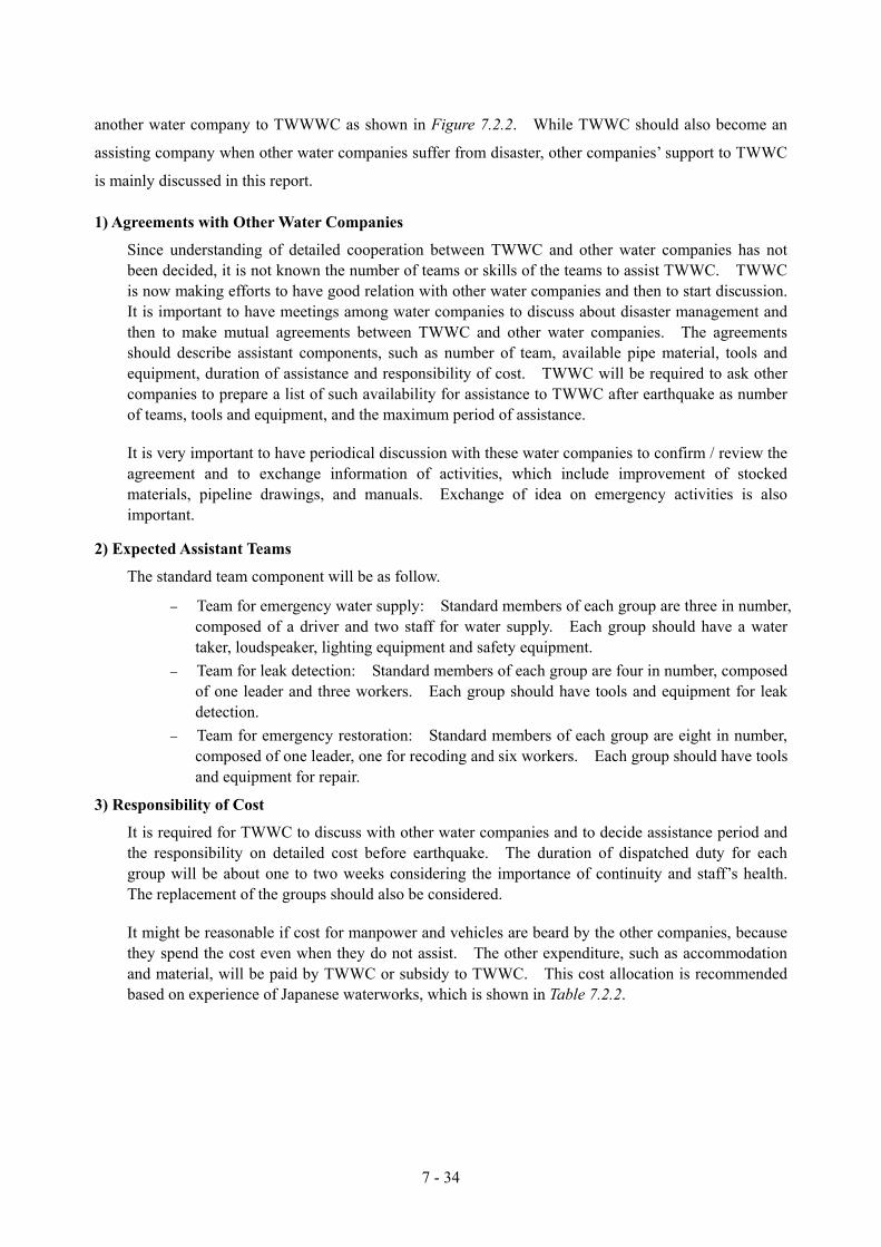
7 - 34
another water company to TWWWC as shown in Figure 7.2.2. While TWWC should also become an
assisting company when other water companies suffer from disaster, other companies’ support to TWWC
is mainly discussed in this report.
1) Agreements with Other Water Companies
Since understanding of detailed cooperation between TWWC and other water companies has not been decided, it is not known the number of teams or skills of the teams to assist TWWC. TWWC is now making efforts to have good relation with other water companies and then to start discussion. It is important to have meetings among water companies to discuss about disaster management and then to make mutual agreements between TWWC and other water companies. The agreements should describe assistant components, such as number of team, available pipe material, tools and equipment, duration of assistance and responsibility of cost. TWWC will be required to ask other companies to prepare a list of such availability for assistance to TWWC after earthquake as number of teams, tools and equipment, and the maximum period of assistance.
It is very important to have periodical discussion with these water companies to confirm / review the agreement and to exchange information of activities, which include improvement of stocked materials, pipeline drawings, and manuals. Exchange of idea on emergency activities is also important.
2) Expected Assistant Teams
The standard team component will be as follow.
− Team for emergency water supply: Standard members of each group are three in number, composed of a driver and two staff for water supply. Each group should have a water taker, loudspeaker, lighting equipment and safety equipment.
− Team for leak detection: Standard members of each group are four in number, composed of one leader and three workers. Each group should have tools and equipment for leak detection.
− Team for emergency restoration: Standard members of each group are eight in number, composed of one leader, one for recoding and six workers. Each group should have tools and equipment for repair.
3) Responsibility of Cost
It is required for TWWC to discuss with other water companies and to decide assistance period and the responsibility on detailed cost before earthquake. The duration of dispatched duty for each group will be about one to two weeks considering the importance of continuity and staff’s health. The replacement of the groups should also be considered.
It might be reasonable if cost for manpower and vehicles are beard by the other companies, because they spend the cost even when they do not assist. The other expenditure, such as accommodation and material, will be paid by TWWC or subsidy to TWWC. This cost allocation is recommended based on experience of Japanese waterworks, which is shown in Table 7.2.2.

7 - 35
Table 7.2.2 The Idea of Cost Allocation in Japan Items Paid by the damaged Water Companies Beard by Assistant Water Companies
Personnel Expenses Allowance for overtime, travel expenses and the others
Salary and basic allowance, which will be paid in ordinal conditions
Materials Cost for pipe materials Contract Works Cost for contract works Vehicles and tools Fuel (gasoline, oil), Repair, Rental
charge, Mobilization Vehicles and Tools brought by assistants
Cost for Stay Foods and Lodging Foods, tents and clothes brought by assistants
Other Expenditure Photo for the works, supply expenses for works, communication. Emergency treatment pay for wounds Compensation for damages (during the assistant works)
Photo for assistant’s usage. Other stationeries. Other treatment pay for wounds Compensation for damages (during mobilization and demobilization)
4) Expected Tools and Equipment to be brought
The other water companies are expected to bring the following for emergency water supply:
− Water tankers, which requires permit for emergency pass − Loudspeakers − Flashlight and lighting equipment − Safety equipment − Engine pump for emergency water supply − Submersible pump and Horse made of clothes − Fuel tank − Temporary water supply tank − Emergency water supply taps − Measuring instrument for residual chlorine − Mobile phone
It is desirable for other water companies to bring following for emergency restoration:
− Vehicles such as crane truck and emergency motor vehicles, which requires permit for emergency pass
− Tools for leak detection such as acoustic rod, electronic leak detector, micro correlator, pipe locator, measure, and pressure gauge
− Tools for pipe jointing (for PVC, PE, SP and DCIP) − Tools for pipe cutting such as cutter, drill, and code reel − Tools for earth work such as drill, hand breaker, pickax, concrete cutter, compactor, and
compressor − Tools for drainage such as submersible pump, generator, and cloth hose − Safety equipment such as signboard, barricade, cone, and lamps − Tools for valve operation such as operation key − Tools for water quality test such as residual chlorine meter − Other tools such as mobile phone, flush light, and camera.

7 - 36
It is useful to know the stock of tools, equipment and pipe materials by other water companies. An example of inquiry form for stored tools and equipment by each water company is shown in Table 7.2.3.
Table 7.2.3 Inquiry Form of Stored Tools and Equipment by Other Water Companies L i s t o f S t o r e d T o o l s a n d E q u i p m e n t
N a m e o f W a t e r C o m p a n y : D a t e : I t e m D e s c r i p t i o n N u m b e r
o w n e d A v a i l a b l e n u m b e r f o r A s s i s t a n c e
R e m a r k s
W a t e r T a n k e r ( m 3 ) W a t e r T a n k e r ( m 3 ) T r u c k C r a n e T r u c k
V e h i c l e
O t h e r s P o t a b l e t a n k ( m 3 ) P o t a b l e t a n k ( m 3 ) P o t a b l e t a n k ( m 3 ) S u p p l y b a g ( ? ) S u p p l y b a g ( ? ) S u p p l y b a g ( ? )
T a n k
O t h e r s E m e r g e n c y T a p s P o r t a b l e f i l t e r G e n e r a t o r ( k V A ) G e n e r a t o r ( k V A ) F l o o d l i g h t p r o j e c t o r P i p e C u t t e r ( m m ) P i p e C u t t e r ( m m ) T h r e a d i n g m a c h i n e
O t h e r T o o l s
O t h e r s
S t r a i g h t P i p e *
F i t t i n g s * *
N o t e : S t r a i g h t P i p e * : P l e a s e s h o w p i p e m a t e r i a l a n d d i a m e t e r F i t t i n g s * * : P l e a s e s h o w p i p e m a t e r i a l , d i a m e t e r a n d t y p e o f f i t t i n g
If other water companies are not accustomed to pipe materials used in Tehran such as DCIP, training should be given to their repair teams. Uniformity of material standard with other cities should be considered.
(3) Assistance from Private Companies
Since private companies will become a great help after earthquake, it is useful to have direct discussion
with several private companies and make agreements if possible. Agreements with private companies
will include the following items
• Items regarding the Contract • Delivery period of goods and contents of work
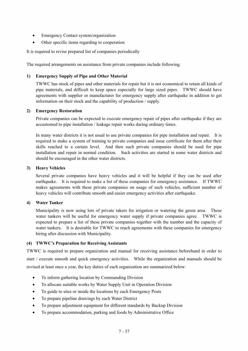
7 - 37
• Emergency Contact system/organization • Other specific items regarding to cooperation
It is required to revise prepared list of companies periodically
The required arrangements on assistance from private companies include following.
1) Emergency Supply of Pipe and Other Material
TWWC has stock of pipes and other materials for repair but it is not economical to retain all kinds of pipe materials, and difficult to keep space especially for large sized pipes. TWWC should have agreements with supplier or manufacturer for emergency supply after earthquake in addition to get information on their stock and the capability of production / supply.
2) Emergency Restoration
Private companies can be expected to execute emergency repair of pipes after earthquake if they are accustomed to pipe installation / leakage repair works during ordinary times.
In many water districts it is not usual to use private companies for pipe installation and repair. It is required to make a system of training to private companies and issue certificate for them after their skills reached to a certain level. And then such private companies should be used for pipe installation and repair in normal condition. Such activities are started in some water districts and should be encouraged in the other water districts.
3) Heavy Vehicles
Several private companies have heavy vehicles and it will be helpful if they can be used after earthquake. It is required to make a list of these companies for emergency assistance. If TWWC makes agreements with these private companies on usage of such vehicles, sufficient number of heavy vehicles will contribute smooth and easier emergency activities after earthquake.
4) Water Tanker
Municipality is now using lots of private takers for irrigation or watering the green area. These water tankers will be useful for emergency water supply if private companies agree. TWWC is expected to prepare a list of these private companies together with the number and the capacity of water tankers. It is desirable for TWWC to reach agreements with these companies for emergency hiring after discussion with Municipality.
(4) TWWC’s Preparation for Receiving Assistants
TWWC is required to prepare organization and manual for receiving assistance beforehand in order to
start / execute smooth and quick emergency activities. While the organization and manuals should be
revised at least once a year, the key duties of each organization are summarized below:
• To inform gathering location by Commanding Division • To allocate suitable works by Water Supply Unit in Operation Division • To guide to sites or inside the locations by each Emergency Posts • To prepare pipeline drawings by each Water District • To prepare adjustment equipment for different standards by Backup Division • To prepare accommodation, parking and foods by Administrative Office

7 - 38
It is required to prepare several plans before the disaster such as:
• Plan on preparation of base camp, lodging and meal service to the assistants • Plan on acquisition and supply of emergency necessities to the assistants • Plan on stock and supply of required equipment for assistant activities • Plan on staff allocation for conductor and guide to assistant groups • Plan on allocation of work and duties to the assistant • Plan on circulation of information to assistants
Following shows the required drawing to be prepared.
• General Map of distribution area to show emergency water supply bases and points, hospitals, schools and other important facilities.
• Distribution pipe drawings with about 1/25000 scale, which shows pipe route, diameter, pipe material, location of valves, and fire hydrants.
• House connection drawings with about 1/500 scale, which shows pipe material, diameter, house, meter and taps.
• Drawings of water treatment plants, reservoirs and other facilities. Ledgers, which show open-close condition of valves, should also be prepared.
• Road route maps, which show important facilities and emergency road. • Location map of material stock yards and waste disposal area.
The drawings should be kept in several locations in order to take quick action after earthquake disaster
and pipe drawings should be updated at least once a year.
7.2.3 Preparation of Manual
It is useful to prepare manual for the emergency activities in order to take adequate and quick action after
earthquake disaster. TWWC should prepare manuals for emergency activities, which explain emergency
water supply activities, plan of emergency restoration, communication system after disaster, agreements
with other water companies and private companies, accepting teams of assistants, and commanding
system to assistant teams. It is important to make all the staff of TWWC understand the manuals, and
periodical execution of maneuvers following the prepared manual will useful for the purposes.
The manuals to be prepared are explained below.
(1) Manual for Initial Activities
The manual should describe following:
• Target of emergency water supply and restoration • Organization chart for emergency countermeasures and duty description of each division • Organization and member of each divisions and sections • Rules for staff gathering

7 - 39
• Gathering locations and allocation of staffs • Collection of information and estimation of damage level • Securing of internal communication • PR activities • Securing of required tools, materials and equipment • Request for assistants (List of contact places such as other water companies and private
companies) • Acceptance of assistants
(2) Manual for Emergency Water Supply
It is required for TWWC to prepare manuals for emergency water supply, which will be very useful for
activities by the assistants. If preparation for acceptance of assistants is insufficient, it will not be easy
for TWWC to give smooth and proper orders to assistants after earthquake disaster. It will be also
difficult for the assistants to take quick and adequate actions since they are not familiar with the sites and
water supply system of TWWC. Therefore the manuals to be prepared by TWWC should include
following:
• Methods of emergency water supply, which includes required tools & equipment together with allocation of TWWC staff and assistants for emergency water supply. The allocated locations are emergency water supply bases, water tankers including direct supply from water tanker, temporary tanks, and temporary water supply taps connected to fire hydrant.
• Location of water supply facilities, which are indicated in general map, pipeline drawings and road maps. The location of emergency water supply bases and of fire hydrant to be used for emergency water supply should also be indicated.
• Location of important facilities such as evacuation places, general hospitals and welfare facilities. These locations should be listed up and indicated in pipeline drawings and road maps.
• List of water tankers to be requested. Owner of water tankers should be checked and listed up. It is important to make previous discussion and arrangement with them.
• The communication methods with assistants. TWWC should select and make clear the staffs in charge of the communication. Improvement of communication among each assistant group should also be considered.
(3) Manual for Reporting of Emergency Water Supply Activities
It is important to know the activities executed and to record the requirements and the results. Therefore
TWWC should prepare manual for uniformed reporting of the activities, which will be used by teams of
TWWC and assistants. The reports should be concise and in written form, which can be filled in short
period. It is necessary to include availability of assistants, activities ordered by TWWC and the results
of the activities.
1) Reports on Availability of Assistants for Emergency Water Supply
The report should consist of available number of staff, water supply methods, number of vehicles, and working period. It should be submitted to TWWC one day before staring the activities. A sample format is shown below.

7 - 40
Table 7.2.4 Sample Form of Reports on Available Assistants
Report on Availability of Assistants Date: Name of Water Company: Number of member Methods of
assistants Number of vehicles Working Hour
Convey water to temporary tanks
Units( m3)
From To
Direct water supplyfrom water tanker
Units( m3)
From To
Distribution of Water Container
Units
From To
Assistance to Water Supply
Units
From To
Total
Total Units
2) Reports on Activities Ordered by TWWC and the Results
Both reports of activities ordered by TWWC and of its results will be used as a basic data for selection of activities to be reinforced and for review of team organization. It is better to combine both reports into one. A sample format is shown below.

7 - 41
Table 7.2.5 Sample Form of Reports on Orders by TWWC and Activity Results
Order by TWWC and Results of the Activities Order by TWWC
Date Name of Water Company
Number of Member
Vehicle Method of Assistants Working Hour
from to
Remarks
Results of the Activities
A B C Location of emergency supply
1 from to m3
from to m3
from to m3
2 from to m3
from to m3
from to m3
3 from to m3
from to m3
from to m3
4 from to m3
from to m3
from to m3
Working Hour
and
Supply volume
5 from to m3
from to m3
from to m3
Number of members
Working Hour from to
Methods of assistants
Convey to tanks Direct supply Water container Assistance of supply
Supplied population
Total supply volume
m3
Water feeding points and frequency
WTP, Reservoir, Wells, others times
Comments
(4) Manual for Emergency Restoration
It is required for TWWC to prepare manuals for emergency restoration, which will be useful for quick

7 - 42
and adequate actions especially activities by the assistants. The manual should include following:
• Basic specification and standard, which include structure of facilities and open / close direction of valves.
• Stored places of drawings and other important documents. These documents should be stored in several locations.
• Methods of emergency restoration. It is necessary to decide methods, such as whether damaged pipes should be repaired or temporary pipes should be installed, before dispatching repair teams.
• Team formation for repair works. Manual should show typical formation, which consists of a leader, persons in charge of valve operation to fill water into pipes, leak detection members, repair technicians and workers.
• Public relation activities to obtain understanding and cooperation on restoration works from the residents. It is important to establish a system for repair teams to convey complain and demands from consumers to head office when they cannot be settled at the sites.
• Selection of priority routes, which should be indicated in pipeline drawings. Transmission pipes, distribution main pipes are the priority routes. The routes to important facilities such as evacuation places, general hospitals and welfare facilities should also be indicated.
• The order of emergency restoration. Restoration works should be principally executed from upstream to downstream. And then, priority routes should be restored in early stage.
• The location of stock yard and waste soil disposal, which should be indicated in drawings. The storage of materials should be controlled in proper manner.
• List of private companies, which can support the restoration works, leak detection works, supply heavy vehicles, supply of materials, and / or supply of fuels.
• Photos of restoration. Photo of original situation, excavation, before and after repair, backfilling, road restoration and final condition at each site should be taken and attached to the reports. The information board is required for photos to show the name of works, slip number, location, date, name of person in charge, and sketch of repaired materials.
• The communication methods with assistants. TWWC should select and make clear the staffs in charge. Improvement of communication among each assistant group should also be considered.
(5) Manual for Reporting of Emergency Restoration Activities
Records of emergency restoration should be compiled since they will become the basic data for
permanent restoration, amendment of pipeline drawings, cost allocation, and others. Since it is better to
use the uniform format, it is necessary to prepare manual for uniformed reporting of the activities.
Emergency restoration groups should submit the reports in the next day of the activities and retain the
copy.
1) Reports on Condition of Damage and Repair
The reports should be prepared for each location and include condition of pipe installation, sketch of damaged location and materials used for repair. A sample format is shown below.

7 - 43
Table 7.2.6 Sample Form of Reports on Damage Condition and Repair Works
Reports on Condition of Damage and Repair Name of Water Company or office: Repair Date: Location Earth condition
Depth
m
Soil sand, sandy, sticky, others
Ground water
Exist, Not exist
diameter mm
Pipe material
DIP, CI, SP, PC, PE, others
Installed Year
Pipe
Type of connection
Push-on, welding, flange, others
Pipe Apparatus
Fire hydrant, Air valve, sluice valve, others
Road cave-in, upheaval, split, others( ) Road vertical, horizontal, bend, break, others( )
Damage
Connection
removal, displacement, split, rubber ring(split, displacement) others( )
Location Map
Excavation, Section (Pavement cm, road bed cm)
Pipe drawing
Description Number Description Number
Material used
2) Records of Restoration of Pipe Breakage etc.
Reports on record of restoration of pipe breakage should be prepared for each location. They should include explanation of accidents, repaired manpower, restoration period, machinery and

7 - 44
sketch. A sample format is shown below.
Table 7.2.7 Sample Form of Records of Restoration of Pipe Breakage and Others
Records of Restoration of Pipe Breakage etc Date Location Damage Contractor Supervisor C Arrival time
Checked by T
Completion time Work period C: contractor, T: TWWC Explanation Size etc unit number
m3 h Excavator m3 h 11 t h 4 t h
Dump Truck
2 t h pump type
pers. Worker h
Traffic control
pers.
Conc. breaker
Driver h Comments
Sketch (Plan) Excavated depth m
In addition to above, blank sketch sheet should be prepared for drawing of repair methods. The information of date, repair number, and location should be filled in the sketch sheet.
(6) Manual for Application of Emergency Traffic Pass
TWWC should obtain emergency traffic pass for required vehicles, which include the cars brought or
owned by assistants in addition to the possession of TWWC. It is necessary for TWWC to discuss with
polices and then to prepare the required procedures as a manual.

7 - 45
Since it will be required for assistants to arrange permission of traffic up to Tehran when they bring
vehicles, previous discussion with the water companies in other provinces on the matter will be required.
(7) Manual for Communication
After earthquake disaster ordinal communication system will be damaged and it will be required to rely
on wireless communication system. TWWC is required to prepare manual for handling of emergency
communication system since it will not be easy for TWWC staffs and assistants to use complicated
wireless communication system. The manual should include following:
• Location maps of stations for several wireless communication systems • Diagram of wireless communication system • List of vehicles equipped with wireless communication system • Handling of equipment • Switching methods to generators • Handling of generators • Recording and reporting of communication • Instructions for communication such as concise commands and uniform terminology
7.2.4 Communication System
Collection and analysis of information form inside and outside of TWWC will become very important
after earthquake. Communication system inside TWWC and with other organization should be prepared
in an effective and correct manner.
(1) Organization for Communication
Internal communication should be done through “Division of Programming and Information”. Quick
and correct information should be collected and transferred to “Accident Commanding Office”, which is
required to give concise and clear instructions / orders to all the divisions of crisis management
organization.
1) Communication with Other Organization
Communication with the organizations outside TWWC should be done in the same manner by Accident Commanding Office. Communication items with TDMO will be as follow:
− Setting up of crisis management Organization in TWWC − Mobilization and deployment of staffs − Damage estimation of water supply system − Information of water suspended area − Emergency water supply and restoration − Required assistance from other water companies, military service, police, red crescent and
other organizations − Other important information
7 - 46
2) Avoidance of Misunderstanding
In order to avoid misunderstanding of communication, the following should be paid attention to:
− To decide and make clear the responsible position of communication beforehand − To unify communication position in order to improve effectiveness and reliability. It is
necessary to avoid numeral sources for commanding, inaccurate information and misunderstanding of the information.
− To unify the name used for communication − To keep records of information and compile
3) Reliable Communication
Required preparation for reliable communication include following:
− To prepare several communication methods since it is predicted that ordinal communication system will be damaged.
− To prepare guideline for communication on type of information and communication manner. The staffs should understand the guideline.
− To prepare format for “information of damage” and other communication − To discuss details of communication system among the crisis management officers and to
improve it.
4) Recording of information
Information should be recorded in a proper manner. The major items to be recorded are as follow:
− Date and time of information receiving − Name and position of TWWC staff − Contacted person and organization − Type of information − Contents of information − Response by TWWC staff
(2) Preparation of Several Communication Methods
It will become difficult to secure communication system after earthquake while the importance of
communication will increase drastically for urgent activities and emergency restoration. Poor
communication methods will disturb the emergency activities. In order to secure reliable
communication, monitoring system should be made as earthquake resistant and several communication
systems should be prepared.
Quick finding of damage and reliable communication will also contribute to prevention of secondary
disaster.
1) Collection Methods of Damage Information
For finding damaged location, following will be useful.
− Telemetry system: For obtaining information of general damage of water supply system, telemetry system is very useful since it is difficult to patrol all the system in a short period.
7 - 47
Damage level of each area will be recognized by observing water flow rate and comparing with the ordinary condition. The information can be used for selection of continuous water supply area and priority activity area. Basic idea for the selection is that water supply will be continued in the minor damaged areas and lots of repair teams will be sent to severe damaged areas.
− Emergency patrol: By patrolling the damaged points or places will be found. Considering the traffic conditions after earthquake, it will be better to use motorbikes for patrolling the area.
− Information from Customers: Education and PR activities to consumers for encouraging the reporting of damage to TWWC will be required.
2) Several Communication systems
TWWC is preparing the several communication methods as listed below
− Telephone and Mobile phone − Telemetry System − Fixed type wireless communication system − Mobile type (mounted on vehicle and potable type) wireless communication system − Internet
Required number of each facility should be studied, considering the activities of collection and conveyance of information for emergent water supply and restoration.
Other communication system, such as information collection by man (on foot, motorbike) and communication to public by mass media, police and military service should also be used as much as possible. It is also desirable to seek the possibility of satellite communication system. Previous planning of the information system is necessary.
3) Required Reinforcement of the System
Reinforcement is found to be required to batteries for reliable communication in emergency cases. The requirement is summarized below.
− Small sized generator should be equipped with batteries for wireless communication system
− At telemetry system, batteries are quipped for about 24 hours. When longer period of power suspension is considered, mobile type generators should be provided at several offices. When generator is used for lighting and telemetry system only, small size generator of 5 kVA will be required. In order to use mobile type generators, previous set up of switch board is recommended.
(3) Public Relation
Activities of public relation (PR) are important methods for communication with consumers. PR
activities will contribute to understanding of the consumers together with increase of information from
consumers.
Important items to inform / ask to consumers for earthquake countermeasures are listed below,
• Problems of water supply system. The information on the problems of the leakage and system damage should be give to consumers.

7 - 48
• Securing potable water by consumers. It is required to recommend consumers to store required water for safety even though TWWC retain sufficient water. The storing methods and period for keeping drinkable water quality should also be explained. The recommended volume of stored water by each family will be “3 liter” times “family members” times “3 days”.
• Methods of emergency water supply by TWWC. The consumer should understand the locations of emergency water supply base and supply point by water tanker. The method of water supply by temporary service taps should also be well informed to consumers.
• Cooperation on emergency restoration: Emergency restoration will disturb the life of residents and their understanding and cooperation are required.
It is required to ask consumers to assist TWWC as volunteers for emergency water supply. Training
should be given to consumers on how to install temporary service taps and serve water to people. It is
also useful to instruct consumers on how to maintain potable water quality by washing water bag in the
training of receiving water from emergency water supply base.
Training and education to consumer are better be done in coordinating with TDMO, who is now
executing several pilot projects to organize inhabitant group and make them understand the required
activities after earthquake. Several seminars and workshops will be held and TDMO is willing to
cooperate TWWC for the training.

7 - 49
7.3 Emergency Water Supply Plan
The target of emergency water supply after earthquake is that 3 liters of water should be supplied at every
1 km distance to all the people in water outage area for the initial three days, and then water supply
amount should be increased to 20 liters up to 2 week period. As shown in the Figure 7.3.1, main water
supply bases are the existing reservoirs and existing wells. The number of the base will be increased by
setting emergency water supply taps to fire hydrant on restored distribution lines.
Supply from Primary Bases
WTP
Supply from Primary Bases, Other Bases andTemporary Tap connected to Distribution Pipe
1 km
Transmission Pipeline
WTP
Reservoir
Reservoir
1 kmWell
250 mReservoir
Reservoir
Well
Transmission Pipeline
Distribution
Primary Bases (set up immediately after disaster)
Supply Area
Other Bases (set up in a phased manner as time goes by after disaster)
Figure 7.3.1 Image of Emergency Water Supply
7.3.1 Methods of Emergency Water Supply
(1) Preparation of Emergency Water Supply
It is important to prepare emergency water supply for smooth execution of emergency water supply
beforehand. The proposed methods for emergency water supply, mobilization of staffs, receiving of
assistants form other provinces, and allocation of teams are described herein. For preparation of the plan
of emergency water supply, following should be paid attention to:
• Estimation of water supply interrupted population • Securing methods of drinking water • Selection of materials and equipment for emergency water supply • Selection of high priority facilities for emergency water supply. Evacuation places, general
hospitals, welfare facilities and other places should be selected for executing emergency activities.
• Initial activities and deployment of required personnel, vehicles etc.

7 - 50
(2) Water Supply at Emergency Water Supply Bases
Consumers in water outage area will get water from emergency water supply bases of every one
kilo-meter. The type and location of water supply bases are explained in Chapter 6.4. Existing
reservoirs are selected as emergency water bases considering the scattered condition of numerous
reservoirs. Special attention should be paid to the security of the reservoir area and avoidance of water
contamination.
When water transmission lines are reinforced, water will be transmitted to all the reservoirs just after
recovery of power suspension, the period of which is assumed as one week. Until the recovery, stored
water in the reservoirs will be used for emergency water supply. Considering the target of emergency
water supply, the amount of water to be stored for each person is calculated as:
3 liter x 3 days + 20 liters x 4 days = 89 liters / person
Two third of the volume of water reservoir is assumed to be remained in the reservoir after earthquake,
because the capacity of the reservoir is about 24 hours of daily average demand and one third of the this
large capacity will be enough for daily demand fluctuation and other daily urgent purposes. A half of
the remaining water, which is one third of the volume, will be used for urgent works such as fire fighting,
and then the other one third is stored for emergency water supply to people. When reservoirs are not
existed in one kilometer distance, exiting wells are selected as emergency water supply bases. These
wells have sufficient yield capacity for emergency water supply and generators are planed to be equipped
to cope with power suspension. Chlorination facilities are also planed to be equipped to keep safety of
drinking water. At the same time, emergency water tanks will be installed to store drinking water in the
area of poor groundwater quality.
These emergency water supply bases will feed water to water tankers and emergency cars such as fire
fighting. Considering the security matter, reservoirs in water treatment plants will not be used as
emergency water supply base for the residents but for feeding water to water tankers and emergency cars.
While TWWC staff should stay in the reservoirs to execute emergency water supply, these works can be
done by assistants from other organizations or volunteers in the bases of wells. Basic members for each
supply point will be three while additional members for the security will be required in some places.
(3) Water Tanker
Emergency water supply bases should cover almost all area of Tehran since water supply by water tankers
will not be easy after earthquake due to heavy traffic and assumed breakdown of many houses.
However, water should be supplied by water tanker in the area of insufficient water supply bases. When

7 - 51
traffic of road is secured after earthquake, water tanker is very useful to transmit water from emergency
water supply bases to temporary tanks to be installed. Water tankers are also helpful in the area of poor
water quality or insufficient water supply. It is necessary to appoint residents to take care each
temporary tank while TWWC staff should patrol to check the maintenance condition of the tanks. When
small sized water tanker is used for narrow road area, water will be directly supplied to consumers from
the tanker. It is desirable to supply water at the same place and to avoid confusion by the consumers.
When sufficient water cannot be supplied in one time, it is required to do even water supply to the
consumers and to inform the schedule of the next supply.
Water should be also brought by water tankers to important facilities, such as general hospitals and
evacuation places, when it is required. It is important to secure sufficient number of water tankers after
earthquake. It is required to prepare a list of the companies, which is now watering the greens by water
tankers, and then to discuss and make arrangement with municipality for emergency usage of private
water tankers after earthquake while TWWC is better to keep sufficient number of water tankers for
emergency. It is also useful to prepare a list of water tankers owned by other organizations such as
military, police, several government offices, and other private companies. Required number of water
tankers should be estimated beforehand and reviewed periodically since the number will change after
emergency water supply bases are prepared.
(4) Water Supply from Temporary Taps Connected to Pipeline
The number of emergency water supply points will be increased by connecting temporary water taps to
fire hydrant when the pipeline is restored and water is filled. It is necessary to select the locations for
temporary water taps, which will not to disturb traffic, and to take safety measures, such as setting of
barricade. Periodical checking of water quality is also important.
The required member for each water supply point will be three who can be assistants form other
organization. The residents in the area and volunteers will be able to perform the key roles for
emergency water supply form temporary taps.
(5) Water Supply by Water Bags or Bottles
Emergency distribution of bottled water will be useful to supplement the emergency water supply
activities. Procurement or donation of bottled water will be required for distribution. Assistance from
bottling companies, which is located outside the damage area, will be helpful and preparation of the list of
the candidate companies and previous discussions are necessary.
It is also recommended to consider introduction of water packing machine for water bag or bottling,
which was used by several water companies in Japan. When packing capacity of one machine is 2 m3
per hour and working period is 15 hours in a day, 30,000 of one liter bag can be prepared. When

7 - 52
minimum water requirement is considered as 3 liter per person in a day, one machine can prepare water
bags for 10,000 people every day. Water bags should be distributed to consumers by vehicles.
7.3.2 Proposed Duty Description for Emergency Water Supply
Sufficient number of emergency water supply teams should be secured just after the earthquake to supply
drinking water in the area of water outage. It is very important to strengthen relations with other
organizations for assistance in emergency water supply through coordination of TDMO. The candidates
of assistant are municipality, water companies of other provinces, Red Crescent, military service and
selected consumers. In Tokyo, each district office in the municipality is responsible for emergency
water supply to people at water supply bases, while waterworks bureau has responsibility on preparation
of emergency water bases and water tankers. This work allocation has big advantage that waterworks
bureau can put much efforts on emergency restoration works after earthquake to expedite the recovery.
Water supply activities at each water supply base can be assisted by ordinary residents after short training,
while water tanker can be arranged by TWWC, private companies, other water companies, and military
service.
The number of required water supply bases after North Tehran earthquake is estimated as 112, which are
located in water outage area. When 3 persons are necessary at each emergency water supply base, 336
persons will be required in total. Sufficient number of assistants will be required even after progress of
repair and decrease of water outage area, because number of emergency supply base in the same area will
be increased.
After earthquake, crisis management organization should be set up as soon as possible. Duties of the
organization members for emergency water supply are proposed as following.
(1) Accident Commanding Division
The major duties for Commanding Divisions regarding to emergency restoration are proposed as follow:
• To ask assistance from other organizations through TDMO • To obtain emergency traffic pass to water tankers and other vehicles, which are necessary for
emergency water supply, by coordinating with police and TDMO. Emergency traffic pass will be required for vehicles of assistants from other water companies, private companies and others.
• To supervise the Laboratory on water quality management of emergency supply.
(2) Operation Division (Water Supply Unit)
Water Supply Unit of Operation Division should coordinate six water districts to do the following:
• To gather information from District Offices and decide emergency water bases to use. • To arrange teams for emergency water supply from Financial and Administrative Division and
assistants from other organization • To arrange required number of water tankers and control them.

7 - 53
• To take responsibility of assistant teams from other organizations. • To arrange material, equipment and vehicle from Supporting Divisions. If number of water
tankers is not sufficient, they should request to private companies and /or TDMO for assistance from other cities and other organizations.
(3) District Office
The major duties of each district office for emergency water supply are proposed as below.
• To survey and get the information of damage and report to the Operation Division • To decide water outage area and inform the Operation Division.
(4) Financial and Administrative Division
Financial and Administrative Division should perform the key roles of emergency water supply in order
for technical divisions to put more efforts on emergency restoration. The major tasks are shown below.
• To allocate manpower of emergency water supply from several sections and other organizations • To execute / take responsibility on emergency water supply to consumer at each bases • To supply water to water tankers/ fire fighting cars at emergency water supply bases. • To coordinate assistants including volunteers at site • To inform Water Supply Section in Operation Division the shortage of assistants and reserved
water if any.
(5) Public Relation
The division of public relation (PR) is necessary to prepare the contents of concise PR for understanding
and cooperation by the residents before earthquake disaster, and then execute careful and kind PR
activities after damage. Previous PR activities by using pamphlet or newspaper will greatly contribute
the improvement of PR effects after earthquake. Contents of previous PR activities for making residents
understand should include following:
• Location of emergency water supply base, • Method of water supply, • Safety keeping measures of water quality • The methods to get information after earthquake • Requirements for water storage by residents • Requirements for preparation of container by residents
Confusion and anxiety of the residents will be reduced if they have sufficient information after earthquake.
The major information to be understood by the residents is as follow:
• Water outage area and water supply area • Damage level of water supply system • Location and time of emergency water supply • Progress of emergency restoration • Measures to keep water quality • Requirement for boiling water before drinking

7 - 54
• Location of complain and demands receiving by TWWC
PR division should put efforts to announce the situation especially in evacuation places and general
hospitals just after earthquake disaster. These activities will reduce number of complains and inquiries
to TWWC. PR division should also ask consumers to give information on leakage and others.
(6) Laboratories
Laboratories should have responsibility on checking of water quality during emergency water supply.
The possibility of water contamination from outside is increased due to damage of pipes and other water
supply facilities after earthquake disaster. This might affect human health and spreading of water bone
disease. It is required to reinforce chlorination system and checking system of residual chlorine at sites.
Maximum attention should be paid to the safety of water quality at emergency water bases under the
responsibility of laboratories. It will be necessary to ask volunteers to check residual chlorine after short
training due to increase of frequency and location of checking. Laboratories should take responsibility
on the training. Simple chlorination methods for chlorination, such as DPD methods, facilities and
guidelines should be prepared and kept at the sites considering that unaccustomed assistants will also
handle it. Together with these efforts, consumers should be instructed to boil water before drinking.
Some groundwater contain high nitrate, which might cause cyanosis to infant, especially in southern part
of Tehran. If water quality of groundwater is found to be unsuitable for drinking after testing, drinking
water should be supplied by water tankers or secured in emergency water tanks and groundwater should
be used for other purposes. Emergency water tanks are required to be installed to supplement well water
for drinking purpose where water supply by water tanker is not reliable. The same arrangement will be
required if the wells locate near factories and there is a possibility of pollution after earthquake. TWWC
has now a plan to change water sources from groundwater to surface water by constructing new water
treatment plant and installation of transmission main in southern part of Tehran. It is recommended to
provide emergency water supply bases connected to the transmission main when the plan is executed.
There is possibility of contamination of groundwater from damaged chemical factories. When it is
anticipated water quality should be checked under control of the laboratories. TWWC is necessary to
survey and find the possible pollution sources and polluting routes before earthquake. When it is
difficult to change water sources, introduction of emergency water treatment equipment using carbon
dioxide, hollow fiber or membrane filters, such as reverse osmosis, should be considered. Several
waterworks in Japan have these emergency water treatment equipments. The equipment of 1 m3 per
hour capacity can supply to about 300 people in one hour when required drinking water is 3 liter per day
for person.
7 - 55
(7) Supporting Division
Supporting Division should take responsibility on storage of materials and equipment. Required
materials and equipment should be listed up and prepared as much as possible. It is required to prepare
maintenance methods of procured tools and equipment, especially the ones which will not be used until
earthquakes occur. It is necessary to distribute the material and equipment at several locations for quick
and easy start of the emergency activities. It is recommended to equip at gathering places with required
materials such as cameras, cotton work gloves, flashlights, keys for valve, manhole openers, flashlights
with generator, fire fighting horse, motor bikes and emergency medical kits. Maps, pipeline drawings,
canned food, cooking tools, folding beds and blankets are also required especially for assistants form
other provinces.
Warehouse is required to be constructed at emergency water supply base and store following:
• Manual for emergency water supply • Chlorine (Calcium hypochlorite) • Simple residual chlorine meter • Engine pump for water supply • Temporary pipes and temporary water supply taps
7.3.3 Emergency Water Supply to Important Facilities
Distribution pipe routes to important facilities should be changed with earthquake-proof pipes with high
priority. Since the activities of strengthening pipelines will take times and huge cost will be required,
several methods should be considered to secure water to important facilities.
(1) Evacuation Place
Emergency water supply bases should be basically set at evacuation places. About one hundred of the
evacuation places are selected in JICA comprehensive master plan and get approval by the government.
The other places are still under the study and waiting for the approval by the government. Total number
of evacuation place will be about 1,000 according to information from TDMO. All of the evacuation
places will be open space such as park, playground, and parks.
Considering the required cost and easiness of maintenance, existing distribution reservoirs will be used as
emergency water supply base. When the evacuation places are located near the existing reservoirs or
other emergency water supply bases, another water supply base will not be installed at evacuation place
but supplemental water supply should be arranged by water tankers and emergency water tanks. The
ordinary consumers will be required to go to the emergency water supply bases in such areas while the
weak consumers will get water from supplemental water supply.

7 - 56
(2) General Hospital
Water distribution system to general hospitals should be reinforced at high priority. By the time of
reinforcement, water supply to the hospitals should be done by using available water distribution pipes
and water tankers after earthquake disaster. It is also required to consider installation of emergency
water tanks at hospitals. Since there is possibility of water shortage even after the efforts of TWWC, it
is required to guide general hospitals to secure water by themselves. TWWC should recommend general
hospitals to prepare deep wells and generator or large reservoirs. The list of the major general hospitals
in Tehran is shown below.
Table 7.3.1 List of Major General Hospitals in Tehran
Capacityof Wells(m3/d)
Ayat Allah Taleghani Hospital Chamran Highway, Tabnak St.
Akhtar Hospital 90 85 - - Elahieh, Pole Roumi, Shariati St.
Amir Almomenin Hospital Shahrara, Niayesh St.
Shahid Modarres Hospital Sadatabad,above kag Sq.
Shahid Rajayee Hospital 500 112 - -
Shahid Hasheminejad Vali Nejad St. After Vanak Sq. Valiasr St.
Hedayat Hospital Hedayat St. Shahrzad Blvd.
Mofid Children Hospital 50 30 - - After Hoseynieh Ershad, Shariati St.
Shahid Labafi Nejad Hospital 25 80 15 41 lit/sec Jafari St. Pasdaran St.
Emam Khomeini Hospital 1000 140 - Keshavarz Blvd.
Boo Ali Sina Hospital Imam Hosein Sq., Tehran No Road
Jaber Hayan clinic Nouri St. No.55, Golnabi St. Pasdaran
Hazrat Fateme Jamaloddin Asadabadi St., No. 21 St.
Shohadaye Tajrish Tajrish Sq.
Tohid Navabe Asadi St. Tohid St.
Shahid Motahari Shahid Yasami St. Vali Asr St.
Amir Kabir Koye Daneshgah, North Karegar
Jamaran Jamaran Sq. Jamaran St. Shahid Bahonar St.
Day Valiasr St., Tavanir St.
ADDRESSName
RequiredWater(m3/d)
Capacity ofW.Tank
(m3)Head(m)
(3) Fire Fighting
About one-third of water in the reservoirs can be used through distribution pipes for fire fighting and
other emergency activities while the remaining one-third capacity should be kept for consumers after
arrangement of reservoir outlet pipes. Fire fighting car can get water from emergency water supply
bases when water is not available from fire hydrant due to damager of distribution pipelines. With the
efforts of TWWC, water disaster might not be sufficient for fire fighting after earthquake. Since

7 - 57
arrangement with Fire Fighting Organization will be coordinated by TDMO, it will be useful to discuss
with TDMO and Fire Fighting Organization on other securing methods of water for fire fighting such as
usage of qanat water and groundwater from wells in parks or for irrigation. TWWC should also suggest
the organization for preparation of generators to use well pumps during power suspension.

7 - 58
7.4 Emergency Restoration Plan
The target of emergency restoration period is set as approximately four weeks in Chapter 5. Number of
assistant teams will largely contribute to the achievement of the target, which is necessary to revise after a
certain progress of the activities. In order to expedite the progress, it is better to set short term target,
which might be as follow:
• Within 72 hours after earthquake: To start restoration of water supply system • Within one week after earthquake: To start water supply through restored system.
Preparation for emergency restoration is indispensable for quick recovery of water supply system and
minimizing negative effects on the consumers.
7.4.1 Procedure and Methods of Emergency Restoration
(1) Initial Estimation of Damage
Information of damage should be collected just after earthquake even if it is before setting up of crisis
management organization. The information will be used for initial judgment of general damage, and
preparation of countermeasures of emergency restoration and emergency water supply.
Damage level should be assumed from indication of abnormality in meters and other instrument. Large
discharge of water from reservoirs or quick drop of water level in reservoirs will be the signal for the
damage in water supply system downstream. Adequate usage of the telemetry system will be very
important after earthquake. If damage level cannot be assumed in office due to power suspension and
other reasons, site survey of important facilities should be done immediately. Information collected by
staff on the way to office should also be used as initial data. For emergency restoration plan, it is
required to collect information of damage on other infrastructures such as gas, electricity, communication,
sewerage and road.
(2) Patrol of Important Facilities
After initial judgment general damage, patrol should be done to know overall damage by checking intake
facilities, damage on bank of dam, appearance of raw water quality, water treatment facility, reservoirs,
pumping station and pipelines. It is also necessary to check informed but unconfirmed damage, effects
of other damage to water supply facilities, such as road and river, and the suspected location of second
disaster by conducting patrol.
(3) Patrol for Finding Damage on Distribution Pipes (By each Water District)
Checking of pipe condition should be started from transmission mains and distribution mains, which are
important pipes, and then goes to sub-mains. Locations of high probability of damage along distribution
mains should be listed up beforehand and be patrolled with high priority. The most probable points, or
weak points, are locations of pipe connection with mass concrete such as reservoirs, valve chambers and

7 - 59
major thrust blocks. Location of fault crossing should also be carefully checked during patrol of
distribution mains. Figures in Chapter 3 show the locations of distribution pipes which cross faults.
(4) Preparation of Emergency Restoration Plan and Execution
Emergency restoration plan should be prepared as soon as possible after finding damage level and crisis
management office is set up properly in TWWC. Decision of priority works, in consideration of
importance and urgency, is required for quick start of restoration. Water outage area should be
diminished as much as possible by adequate adjustment of water distribution following the process of
emergency restoration plan. It is required to consider the items below for preparation of emergency
restoration plan.
• To know the condition of the major facilities • To select safe transmission and distribution mains together with reliable supply area • To assume damaged / to be damaged transmission and distribution mains and damage points • To decide restoration period • To select high priority for emergency restoration • To select methods of emergency restoration (repair or installation of temporary pipe) • To secure and distribute required materials and equipment • To study process of emergency restoration • To arrange repair teams (members, vehicles and supporting companies) • To know the restoration of other lifeline such as sewer system • To keep safety of water quality by strengthening chlorination for resuming wares supply after
emergency restoration.
The typical repair works will be a repeat of filling water into pipe, checking water pressure, leak detection
or survey, and pipe repair. Restoration of pipes along important roads should not disturb emergency
traffic and it is necessary to study previously the methods, which will be either usage of bypass or
installation of temporary pipes.
The emergency restoration plan should be revised after progress of the activities considering damage
level, assistant’s activities, condition of bypass pipes, water supply interrupted population, sufficiency of
emergency water supply, and the priority.
(5) Detailed Investigation
The detailed survey of each facility should be done with staffs, who know well about each facility, to
supplement the initial information of each facility. The survey will be done, in parallel with emergency
restoration work, to clarify ground condition, detailed damage, and progress of restoration. In order to
avoid confusion, all the information should be collected dominantly by Division of Programming and
Information Processing and reported to Accident Commanding Office. Damage level of other
infrastructures will be collected mainly from TDMO. Finally the research should be done to collect

7 - 60
information for future study on the causes of disaster and disaster prevention methods.
(6) Filing of Damage Data and Recording for Permanent Restoration
Division of Programming and Information Processing should investigate damage and compile the records
consistently. It is required to prepare format of damage information as described in Section 7.2.3
Preparation of Manual. The survey results should be compiled for each facility and used for deciding
restoration methods, procurement of material and equipment, required people for restoration, and
allocation of assistants. Location of pipeline damage should be clearly marked in pipeline drawings.
Drawings of emergency restoration of pipe should be recorded properly in order to be used for permanent
restoration after emergency restoration. The drawing should explain information of damaged parts,
which includes pipe diameter, material, fitting and earth cover. Permanent restoration should be done by
replacement of temporary repair or further leakage investigation and repairs, taking into account of future
plan. It is important to prepare a format for recording the restoration plan, instruction of repair and daily
records of restoration as shown in Table 7.2.6 and Table 7.2.7. Photos of restoration should be attached
to the records and filed after restoration.
7.4.2 Proposed Duty Description for Emergency Restoration
Duty description is required to be prepared and distributed to all the related divisions and sections in order
to make clear understanding. Proposed duty description of each division is listed below:
(1) Commanding Division
The major duties for Commanding Divisions regarding to emergency restoration are proposed as follow:
• To ask assistance from other water companies and private companies • To obtain emergency traffic pass for vehicles of emergency restoration, which come from other
water companies, by coordinating with police and TDMO.
(2) Operation Division (Water Supply Unit)
Water Supply Unit of Operation Division should coordinate six water districts. Proposed major duties of
Operation Division are the following:
• To decide allocation of repair teams to sites considering information from all the District Offices • To arrange repair teams among districts. Teams should be sent to seriously damaged districts
from the other districts. • To take responsibility of assistant teams from other provinces and decide the water district to
work • To give updated pipe drawing to assistants from other district and other cities • To coordinate assistance of private companies • To collect information from each District Office and select priority areas and facilities to be
repaired • To request required material, equipment and vehicles to Supporting Divisions.

7 - 61
• To secure place for waste material and removed soil • To compile the reports from all the repair teams
(3) District Office
Major duties of each district office for emergency restoration are proposed as below.
• To survey and get the information of damage • To report damage to Operation Division • To select and send assistant teams to other district or receive assistant teams upon instructions of
Operation Division • To decide the priority job and allocate repair teams and equipment to the emergency posts. • To provide required material and equipment upon the request by Emergency posts. • To secure shortage of manpower and vehicles from private companies. If it is insufficient,
request to Operation Division • To prepare emergency restoration plan of each district. • To prepare/ update pipeline drawing, which shows location of valves, and give to head office of
TWWC • To give updated pipe drawing to assistants from other districts and other cities • To list up and summarize the required tools and equipment. Send the lists to the head office.
Head office should provide them to district offices • To arrange location for temporary soil disposal
(4) Emergency Posts
Emergency posts are responsible for actual emergency restoration at sites. The major duties will be
below.
• To get information of damage and report to District Office • To repair pipes starting from high priority area • To collect reports from all the repair teams • To report progress of restoration to District Office • To secure required material and equipment. If they are insufficient, emergency posts should
report it to District Office, which will request to Operation Division if they are not available. • To give guides to assistants from other water districts or other cities
(5) Supporting Division
Supporting Division is responsible for storage and supply of pipe material, heavy machinery, tools and
equipment.
1) Storage of Materials and Equipment
Adequate tools and equipment should be prepared for restoration teams and especially for assistants since they might use different type. Pipe materials of large size will not be economical to store if they are not necessary in ordinal times. When the stock of pipe materials and other tools are insufficient, they should be brought from supplier / manufacturer as soon as possible. It is required to ask support and to keep good relation with relevant private companies during ordinary times. Support from private companies will also be expected for other requirements, such as chemicals for

7 - 62
water treatment and fuel for generators.
It is recommended to consider following for preparation of storage:
− Pipe material and sleeve coupling for several size of pipe, which will be required for daily leak repair works, should be stored.
− List of material stocked by TWWC should be prepared. After private companies start pipe installation work, list of stocked materials by these companies should also be prepared.
− If emergency materials are insufficient, they should be procured from manufacturers or other water companies.
− It is desirable to prepare list of stocked materials by water companies in other provinces and to exchange it.
− Sufficient stock should be kept for the period until manufactures or other cities can supply them.
− Materials, which are required long period for procurement, are better to be procured beforehand.
− Materials and equipment should be kept in several locations such as emergency posts and other distribution reservoirs in order to take quick actions after earthquake.
Table below summarizes the recommended list of material and equipment for restoration of building.
Table 7.4.1 Recommended List of Material and Equipment for Restoration of Building
I t e m S p e c if ic a t io n U n it N u m b e r I t e m S p e c if ic a t io n u n it N u m b e r
w id e - f la n g e (H ) s h a p e ss t e e l
H - 1 0 0 * 1 0 0 ,L = 4 m p c s 2 0 t r u c k w it h c r a n e u n it 5
I- s e c t io n s t e e l I- 2 0 0 * 1 0 0 ,L = 4 m p c s 2 0 t r u c k ( 4 t ) u n it 5
e q u a l le g a n g le L - 5 0 * 5 0 * 6 、 L = 5 m p c s 2 0 t r u c k ( 2 t ) u n it 5
s t e e l t u b e f o r t u b la rs c a f f o ld in g
3 0 0 0 * φ 4 8 * 2 .4 t p c s 1 0 0 P o r t a b le G e n e r a t o r G a s o l in e u n it 1 0
c la m p f o r t u b la rs c a f f o ld in g
F o r s t r a g h it p ip e p c s 2 0 0 G e n e r a t o r G a s o l in e , 3 .0 k V A u n it 5
b a s e p la t e fo r t u b la rs c a f f o ld in g
F o r s t r a g h it p ip e p c s 5 0 W e ld in g M a c h in e E n g in e t y p e u n it 5
ja c k f o r t u b la rs c a f f o ld in g
F o r s t r a g h it p ip e p c s 5 0 E le c t r ic D r il l u n it 5
lo g fo r s c a f f o ld in g φ 7 5 * 4 m p c s 5 0 P o r t a b le d r a in p u m p u n it 5
b o a r d f o r s c a f f o ld in g 3 6 t * 2 0 0 w * 4 m s h e e t 5 0 E le c t r ic G l in d e r u n it 1 0
s c a n t l in g , w o o d e n b lo c k 9 0 * 9 0 * 3 0 0 0 L p c s 5 0 B a b y W in c h 1 5 0 k g u n it 1 0
f ib e r l in e r o p e m 2 0 0 C h a in b lo c k 1 t o n u n it 5
w irw r o p e φ 2 0 m 1 0 0 J a c k L if t 1 5 t , M a n u a l u n it 5
s t e e l w ir e # 8 φ 4 .0 m 1 0 0
h o le - in - a n c h o r φ 1 2 p c s 1 0 0 G e n e r a l T o o ls S e t 1 0
p ly w o o d 1 2 * 9 0 0 * 1 8 0 0 s h e e t 1 0 0
a f ir e h o s e φ 5 0 m 1 0 0
p r o je c t e r 3 0 0 W p c s 2 0
w e ld in g t o o l u n it 5
w e ld in g r o d p c s 1 0 0
p la s t ic s h e e t f o rc o n s t r u c t io n
1 8 0 0 * 3 6 0 0 * 0 .4 s h e e t 2 0
Notes: 5 sets are considered to be equipped at WTP1,2,3,5 and a Vehicle Base in southern area.

7 - 63
2) Heavy Vehicle
In addition to manpower, it is very important to secure sufficient number of heavy vehicles with their operators for expediting restoration works. Methods for securing heavy vehicles are summarized below.
− To procure by TWWC itself − To coordinate with other water district offices in TWWC − To make agreement with private companies. It is required to prepare a list of private
companies who has heavy vehicles. − To request to military force, municipalities and other organizations through TDMO − To ask assistance from other water companies
The availability in other organizations and private companies should be listed up beforehand.
7.4.3 Other Important Issues for Emergency Restoration
(1) Priority Selection of Restoration
It is required to restore damaged pipes from upstream of the route or main pipes to down stream as
described in Section 7.1. Upstream of heavy damaged system has high priority for restoration.
High priority routes to important facilities such as general hospitals, evacuation places, welfare facilities,
political facilities and religious facilities should be selected and shown in map. After restoration of
transmission mains, these roués should be restored quickly.
(2) Increase of Emergency Restoration Teams
Following can be considered in order to increase number of restoration teams without delay.
• Quick gathering of TWWC technical staff should be secured after earthquake • Asking assistant restoration teams from other water companies • Request private companies for assistance. • Asking retired skilled workers. Previous preparation of list and coordination will be required.
(3) Training
It should be repeated that only a few private companies are working for pipe replacement / installation
and have capability of emergency restoration at the moment. It is required for TWWC to give training
to private companies. It is recommended to give certificate after they get required skills and then work
together during ordinary times in order to retain and improvement the capability of pipe restoration. The
contribution of private companies is indispensable for increasing the number of emergency restoration
teams and for satisfaction of the target.
Assistant groups of other water companies should have adequate skills for restoration of pipes in Tehran.
It is necessary for TWWC to consider the training to them if they are not accustomed to pipe materials in
Tehran or their skills are insufficient.

7 - 64
(4) Improvement of Pipe Network System
Improvement of pipe network system, especially “separation of distribution system from transmission
system” and “distribution block system”, will contribute emergency restoration in following aspects:
• It will become easy to cutoff small pipes, which are easy to be damaged, from important large sized main pipes when the function of transmission pipes, distribution main and sub-main is clearly separated. It will contribute to improvement of main pipes against earthquake and to securing water for restoration.
• It will become easy to increase number of emergency water supply points by keeping function of main pipes
• It will become easy to decide priority of restoration works as it becomes easy to understand water flow.
• By securing function of main pipes, the number of restoration places will be increased. • It will easy to give the whole water supply block to assistants form other water companies for
repair. • By checking night flow data in each water supply block, it becomes easy to check the leakage
after emergency restoration work, • By isolating each water supply block, water supply interrupted area can be minimized. • It becomes easy to know damage level and to restore because the area is separated into water
supply blocks. • Backup from the fringe water supply block will become easy
(5) Importance of valve installation
Operation of valves at proper locations is very important for expediting emergency restoration and for
prevention of secondary disaster. It is necessary to make clear the location of all the valves for the staff
of other sections so that they can also approach. It is also required to check accessibility and condition
of installed valves periodically. Whenever necessary, it is required to install new valves without delay.
(6) Securing Water for Restoration
Large amount of water will be required for emergency restoration after earthquake disaster because
damaged points are basically found by leakage. In other word, without filling water to pipes, it will be
difficult to find leakage. When sufficient water is secured for restoration, water supply can be continued
for expediting emergency restoration works even if there are some leakages. It was found that the area
with larger amount of water supply could be restored fast after Kobe earthquake. Maximum usage of
groundwater should be considered for quick restoration work in Tehran.
The possibility of large amount of leaks is high in Tehran since water is basically supplied by gravity.
Therefore it is required to install emergency shut off valves or to arrange pipes at outlet of reservoir to
secure water not only for emergency water supply but also for expediting emergency restoration.